Embed Size (px)
Citation preview

7 3 29 9 4 5
NASACR-132264
Cyilaiers SiiDimm 01 cewsiieoied (o cow
By R. L. Carri
June 1973
Prepared under contract NAS1-11817 byGRUMMAN AEROSPACE CORPORATION
Bethpage, New York
for
Langley Research CenterNATIONAL AERONAUTICS AND SPACE ADMINISTRATION
https://ntrs.nasa.gov/search.jsp?R=19730021213 2018-06-28T00:45:33+00:00Z

FOREWORD
This report was prepared by Grumman Aerospace Corporation, Bethpage,
L.I., New York under contract NAS1-11817, "Buckling Behavior of Composite
Cylinders Subjected to Compressive Loading". Analysis and fabrication of
specimens was performed at the Grumman Corporation facilities. Instrumenta-
tion, testing and comparisons of several analytical buckling theories were
performed at the MSA Langley Research Center.
This contract was conducted under the sponsorship of the Materials
Application Branch of the Materials Division of the NASA Langley Research
Center. Mr. H. Benson Dexter, Composites Section, was the NASA project
monitor. The program manager at Grumman was Mr. R.N. Hadcock and the
assistant program manager was Mr. S.J. Dastin.
The author wishes to acknowledge the following individuals who have
contributed to the program.
Mr. A. Angiola
Mr. R. Collins
Mr. A. DeAngelis
Mr. G. Golam
Mr. M. Kanal
Dr. J. -Whiteside
Structural Design
Quality Control
Manufacturing Engineering
Materials and Processes
Structural Analysis
Structural Mechanics
ii
CONTENTS
PAGE
SUMMARY 1
INTRODUCTION 1
SYMBOLS 3
MATERIALS AND SPECIMENS 5
.TEST METHODS 7
TEST RESULTS 7
ANAEYSIS 8
COMEARISON OF TEST DATA WITH ANALYSIS 15
CONCLUDING REMARKS 15
APPENDIX A 17
APPENDIX B 18
APPENDIX C 19
REFERENCES 21
iii

BUCKLING BEHAVIOR OF COMPOSITE CYLINDERS
SUBJECTED TO COMPRESSIVE LOADING
By R.L. Carri
SUMMARY
Room feHmperature corapressive buckling strengths of eight cylinders,
four boron-epoxy and four boron-epoxy reinforced-titanium, with diameter
to thickness .ratios ranging between UO and 6? are determined experimental-
ly and conrpasred with analytical predictions. Numerical buckling strengths
are presented for Donnell's, Flugge's and Sanders' shell theories for
anisotropic and orthotropic material cases. Comparison of analytical pre-
dictions wit3h experimental results indicates good agreement and the recom-
mended correction factor suggested in the literature is applicable for
design. Fear the cylinders tested in this investigation the correlation
between experiment and theory ranged from 0.73 to 0.97.
INTRODUCTION
In reesit years the use of high modulus and low mass composite
materials, isost notably boron-epoxy, for the fabrication of lightweight
tubular compression members has been successfully demonstrated. Initial
experimental, investigations (Refs. 1 and 2) were based on the compres-
sive strength and column efficiencies of tubular members while recent
hardware oriented programs (Refs. 3 and h) included designing for local
buckling modes of failure.
The technology to structurally optimize and analyze a composite
tubular comparession member for geometrical configuration, filament
orientation and stacking sequence has been reasonably defined (Refs. 3,
5 and 6). However, experimental results are lacking for local buckling
of composite cylinders particularly for diameter-thickness ratios (D/t)
approximately equal to 50. The purpose of this program was to establish
a correlation between theoretical and experimental compressive buckling
strengths for boron-epoxy composite cylinders and boron-epoxy reinforced-
titanium cylinders with D/t's < 70.

Page intentionally left blank

SYMBOLS
The units for physical quantities used in this report are given in
both the International System of Units (Si) and the U.S. Customary Units.
Measurements and calculations were made in U.S. Customary Units. Conversion
factors relating the two systems are given in Reference 7> and those perti-
nent to this report are presented in Appendix A.
D mean cylinder diameter, meters (inches)
D-..,Dpp bending stiffness per unit width of wall in longitudinal
and transverse direction, newton-meters (pound-inch)
E,,,Ep2 Young's moduli of orthotropic material in longitudinal
and transverse direction, newtons/meter (pounds force/inch )
E, ,,Epp extensional stiffness of wall in longitudinal and transverse
direction; E^ = Ellfe ; E22 = E22t , newtons/
(1'V12V21) (1"V12V21)
meter (pounds force/inch)
L length of cylinder, meters (inches)
1 length of transition region near end of cylinder where localtrbending occurs, meters (inches)
M bending moment in cylinder wall per unit width of circumference,
newton-meters/meter (pound force-inches/inch)
M ,V bending moment and radial shear force in cylinder wall, at
end of cylinder, per unit width of circumference, newton-meters/
meter (pound force-inches/inch); newtons/meter (pounds force/inch)
n • number of full waves in cylinder buckle pattern in circum-
ferential direction
N axial load per unit width of circumference for cylinderX.
subjected to axial compression, newtons/meter (pounds force/
inch)

P compressive axial load, newtons (pounds force)
r mean cylinder radius, meters (inches)
t thickness of cylinder wall, meters (inches)
tR local thickness of cylinder wall in reinforced region,
meters (inches)
x coordinate in the longitudinal direction of cylinder
Y. distance from the neutral axis of the laminate to the ith
layer, meters (inches)
Y correlation factor to account for disparity between analytical
and experimental buckling loads
v-,p,Vp-| major Poisson's ratio and minor Poisson's ratio, respectively
Subscripts
cal calculated
exp experimental
i ith layer of a multilayered composite
max maximum
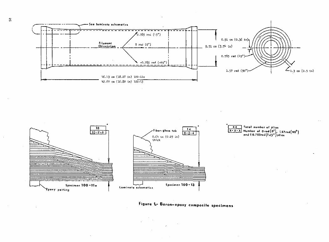
MATERIALS AND SPECIMENS
The experimental program consisted of room temperature axial
compression testing of eight cylinders, four boron-epoxy composite and
four boron-epoxy reinforced-titanium. The specimens were designed to
fail in tbe local buckling mode, and ranged from 38.1 cm (15.0 in.) to
1*6.k cm (lB.3 in.) in length and had mean diameters ranging from 9.27
cm (3.65 in..) to 9.78 cm (3.85 in.). Details of the cylinders are
illustrated on Figures 1 and 2 for the boron-epoxy composite and the
boron-epozy Teinforced-titanium specimens, respectively. Local buckl-
ing failures in the straight portion of the cylinders were desired, so
additional tmidirectional plies were added at the ends (Figures 1 and
2) in an attempt to preclude failures due to support and rotational
restraints. The specimens were fabricated in two phases. Those with
the letter ra' were fabricated after the first three were tested. The
decision to ok> this was based on incorporating design revisions for the
cylinder ends should they be required. Based on the successful Phase 1
test results the end reinforcement concept was considered satisfactory
and no revisions were necessary. Table I presents the basic geometry,
laminate orientation, and stacking sequence for all of the individual
specimens. The boron-epoxy material required for fabrication of all
specimens was purchased to existing Grummar specifications in 7.62 cm
(3.00 in.) wide tape containing 0.01 mm (O.OOU in.) diameter filaments
preimpregnated with a U50 K (350°F) stable epoxy resin system.
BORON-EPOXY COMPOSITE SPECIMENS
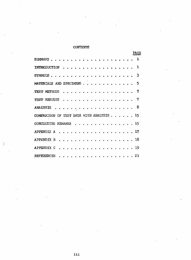
The approach used to fabricate the all-composite specimens was based
on panel processes, so that the tube properties, both mechanical and phys-
ical, are similar to those of flat laminates. This was accomplished using
a male mandrel upon which the plies of boron-epoxy prepreg and bleeders
were convolute wrapped (see Figure 3) and then transferred to a female

mold form prior to curing. The proper number of bleeders and boron-epoxy
plies were wound on the mandrel so that the resulting layup was 0.013 cm
(0.005 in.) to .051 cm (.020 in.) smaller in diameter than the correspond-
ing inside diameter of the female mold. This tolerance is required to
permit proper fitting of the wrapped assembly into the female mold while
still providing a fit-up that results in a controlled volume fraction
array in the cured cylinder. Figure h shows the aluminum male mandrel and
the two piece steel female mold form, the inside surface of which is the
tool face. A production tube wrapping machine (Figure 5) was used to
facilitate the continuous wrapping of all specimens. The wrapping machine
consists of.a wind-up roller, pressure roller, vacuum table and tube layup
mandrel. This continuous wrapping technique utilizes a mylar template,
Figure 6, on which individual plies of boron-epoxy are accurately placed prior
to wrapping. Information on the template includes the individual ply
number, trim, filament orientation, position, slit locations, and template
feed rate. To utilize this wrapping technique the mylar template is drawn
based on calculating the individual ply developed lengths and includes
overlap requirements of .91 cm (.36 in.) for the +.785 rad (+V?0) angle
plies and 1.27 cm (.50 In.) for the 1.57 rad (90°) plies. In addition
the 1.57 rad (90°) plies are split longitudinally into two segments,
such that the ply is layed up in two halves with one half overlapping the
other. This permits the prepreg to expand to the female mold during the
cure cycle,
BORON-EPOXY-REINFORCED TITANIUM SPECIMENS
Fabrication of the boron-epoxy reinforced-titanium cylinders
consisted of mounting the pretreated and primed, titanium substrate on
an aluminum mandrel. A single ply of a film adhesive, Metlbond 329
Type 1A, was applied to the titanium followed by the individual boron-
epoxy plies, nylon peel ply and spiral wrapped bleeder plies. The tube
wrapping machine was used to- continuously wrap these specimens also.
The bleeder system was tightly overwrapped with plastic shrink tape and
the assembly envelope-bagged for curing.
All specimens fabricated for the program were autoclave cured at
K (350°F) in accordance with the cure cycles included in Appendices
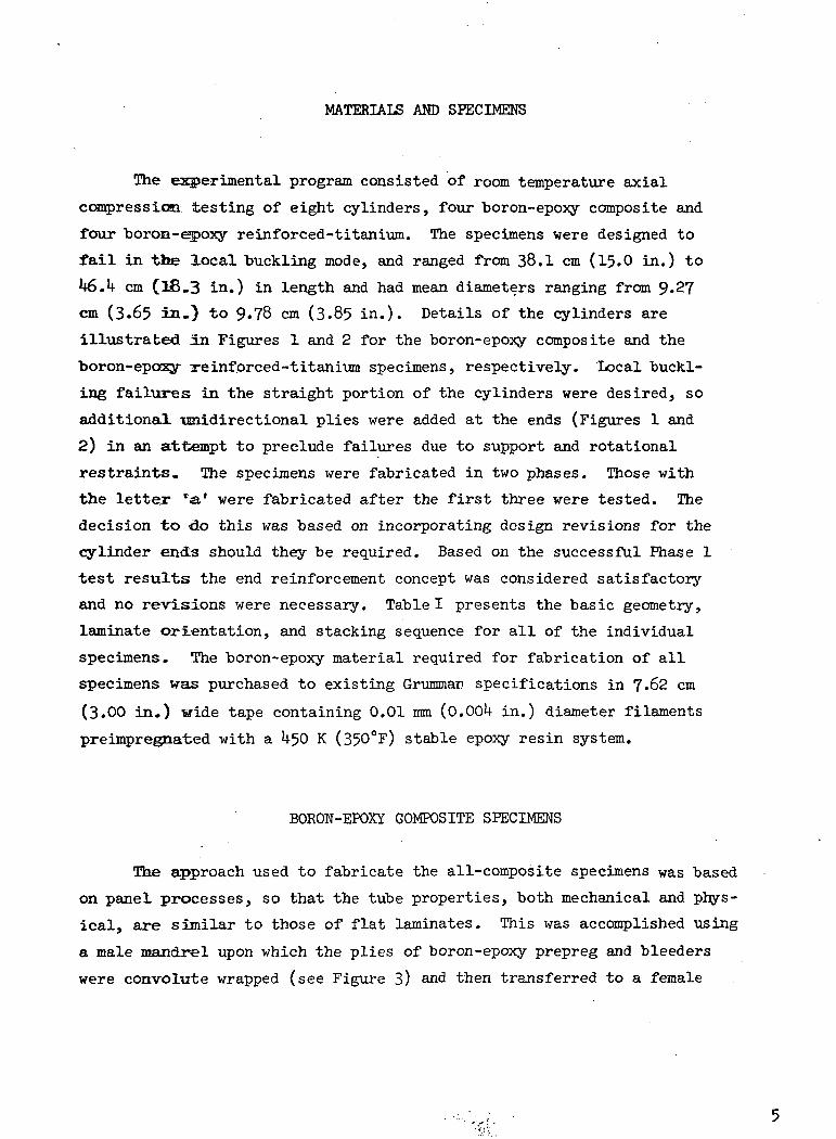
B and C and post-cured in an oven at 63 K (375°F). Photomicrographs of
typical cross sections of the fabricated specimens (Figure 7) show the
uniformity of the filament spacings which resulted from the fabrication
processes used.
TEST METHODS ;
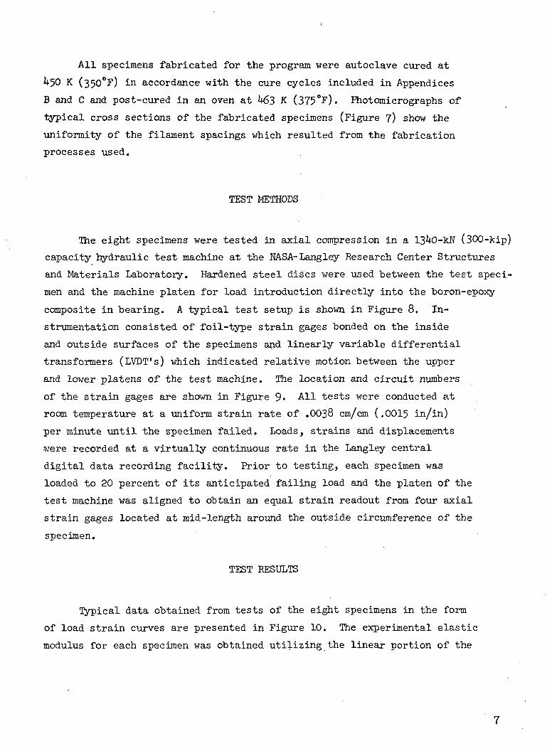
The eight specimens were tested in axial compression in a 13 0-kN (300-kip)
capacity hydraulic test machine at the NASA-Langley Research Center Structures
and Materials Laboratory. Hardened steel discs were used between the test speci-
men and the machine platen for load introduction directly into the boron-epoxy
composite in bearing. A typical test setup is shown in Figure 8. In-
strumentation consisted of foil-type strain gages bonded on the inside
and outside surfaces of the specimens and linearly variable differential
transformers (LVDT's) which indicated relative motion between the upper
and lower platens of the test machine. The location and circuit numbers
of the strain gages are shown in Figure 9- All tests were conducted at
room temperature at a uniform strain rate of .0038 cm/cm (.0015 in/in)
per minute until the specimen failed. Loads, strains and displacements
were recorded at a virtually continuous rate in the Langley central
digital data recording facility. Prior to testing, each specimen was
loaded to 20 percent of its anticipated failing load and the platen of the
test machine was aligned to obtain an equal strain readout from four axial
strain gages located at mid-length around the outside circumference of the
specimen.
TEST RESULTS
Typical data obtained from tests of the eight specimens in the form
of load strain curves are presented in Figure 10. The experimental elastic
modulus for each specimen was obtained utilizing the linear portion of the
curves corresponding to the strains at mid-length of the specimens. Fail-
ure of the specimens occurred at the indicated maximum loads which coincided
with the buckling loads for the all-composite specimens, see Figures 10(a)
and (b) . The load strain curves for the composite-reinforced titanium
specimens indicated a varying degree of strain reversal prior to failure as shown
in Figures 10 (c),(d) and (e). The coalescence of buckling and material
failures is attributed to the low D/t ratios of the specimens. Load de-
flection data for all specimens was linear to failure. A typical load de-
flection plot is shown in Figure 11.
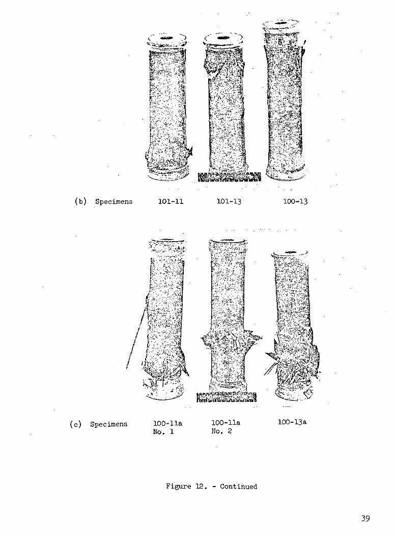
Photographs showing the location and type of failures'are presented
in Figure 12. Figure 12(a) illustrates local buckling of a typical all-
composite specimen and shows the complete composite ma'terial failure which
was typical of all specimens tested. There were no discernable buckles or
indications of failure prior to ultimate collapse. All failures occurred
almost instantaneously and were accompanied by a loud noise and a sudden
reduction in load. Figure 12(b) shows the failures obtained for the initial
three specimens tested during phase one. The shiny surface appearance of the
cylinders resulted from a protective epoxy spray coating applied to the first
three specimens after fabrication. This coating caused difficulty in strain
gage installation and was omitted on the second group of specimens. Figures
12(c) and 12(d) are photographs showing the failures for the second group of
specimens. The material failures of the all-composite specimens shown in
Figure 12(c) are more pronounced than the failures of the composite-reinforced
titanium specimens 'shown in Figure .12(d). This is even.more evident when com-
paring the end views of the failed composite-reinforced titanium specimens
shown in Figure 12(e) with those of the all-composite ones shown in Figure
12(f). The titanium acts to restrict the failure to a localized area where
the titanium is buckled.
ANALYSIS
Selection of Specimen Configurations
The specimen geometries presented in Table I were determined by
several considerations. A diameter sufficient to facilitate, the installa-
tion of strain gages on the inside surface of the specimens was required.

Laminate thickness was selected to produce a low D/t ratio such that
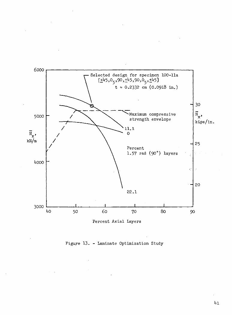
local stability was critical under axial compressive loading. The all-
composite cylinders, 100-lla and 100-13, were optimized by varying the
percentages of lamina orientation and the stacking sequence to yield the
highest theoretical buckling stress for the 0, +0.785, 1.57 rad (0°, +j+5°,
90°) family of laminates. This was accomplished using the orthotropic non-
homogeneous buckling analysis of Reference 5» which is based on small deflection
buckling theory and Donnell-type stability equations. Figure 13 shows the
results of the optimization study performed for specimen 100-ll(a). The
maximum compressive strength envelope shown in the figure is the inter-
laminar shear cutoff for boron-epoxy which remains relatively constant
for laminates having more than 50 percent of 0 rad (0°) filaments.
The configurations of the composite-reinforced titanium specimens
are based on three considerations. First, the calculated stress in the
titanium substrate at buckling, including the residual stresses result-p
ing from the elevated cure of the composite, must be below 821 MN/m
(119.0 ksi), the stress at which the tangent modulus decreases sharply
for annealed Ti-6AI-kV (see Figure 1 ). Second, an overwrap of
a pair of angle plies +0.785 rad ( 5°) is necessary to prevent longi-
tudinal cracks from developing in the composite material due to the
transverse residual stresses resulting from the dissimilarities of the
constituent material coefficients of thermal expansion and Youngs moduli.
The third consideration was to select three arbitrary percentages of
boron-epoxy composite reinforcement to verify the selective reinforce-
ment concept for various D/t ratios.
Cylinder Buckling Strengths
/The method of analysis initially used to predict the compressive
buckling strengths of all specimens was based on Donnell-type stability
equations for multi-layered orthotropic cylinders (Ref. 5). Because of
the apparently low buckling strengths obtained from the first three speci-
mens tested, it was decided to examine other buckling analysis methods.
This investigation was conducted by H. Benson Dexter of the Composites

Section at Langley during the fabrication of Phase II specimens and the
results were not obtained in time to incorporate possible changes in the
specimen laminate configurations, which had been optimized for Donnell's
theory.
The accuracy of Donnell's equations were investigated by Hoff (Ref.
8) for isotropic shells. Hoff shows that Donnell's equations can result
in considerable errors for cylinders that buckle with a small number of
circumferential waves (n < h). Hoff also recommends that Donnell's theory
should be replaced by a solution of the Flugge equations when the cylinder
is short. Since the Donnell theory indicated buckling mode shapes of (n < k)
for all specimens tested in this program, it was decided to reanalyze the
cylinders using Flugge and the more recent Sanders shell theories.
Numerical results for Flugge's theory were obtained using an iteration
scheme to find the critical buckling load. The procedure developed and coded
by Wu (Ref. 9) is applicable for general anisotropic cylinders with arbitrary
ply orientations. Numerical results for Sanders' theory were obtained using
the SALORS (Structural Analysis of Layered Orthotropic Ring-Stiffened Shells)
computer program (Ref. 10). This program which uses a finite difference pro-
cedure for solution of the buckling problem was developed at the NASA Langley
Research Center.
Buckling strengths for all specimens were calculated both for the
classical simple support and clamped boundary conditions. The material
properties used In the calculati'ons ,are presented in TablelL A summary
of the theories and orthotropic and anisotropic cases for which numerical
results were obtained are as follows:
o Flugge:
Anisotropic - (Ref. 9)
Orthotropic - (Ref. 9)
o Sanders:
Orthotropic - (Ref. 10)
o Donnell:
Anisotropic - (Ref. 9 )
Orthotropic - (Ref. 9 )
Orthotropic - (Ref. 5 )
10
For the anisotropic cases, the material properties for each ply were
required input for the computer program. The orthotropic cases required
successive +.?85 rad ( 5°) plies to be lumped as a single layer. All con-
secutive 0 rad (0°) and 1.57 rad (90°) plies were also lumped as discrete
layers of their respective orientations. Analytical results are presented
in Table III for the simple support boundary conditions. Results for the
clamped boundary conditions were omitted since they differed from the simple
support values by less than 5 percent. The specific results presented in
Table III show reasonable agreement between Flugge's and Sanders theories
with a maximum difference in predicted buckling load of less than 6 percent
for specimen 101-11. In contrast, the discrepancies in results between the
Flugge and Donnell theories are extreme. The buckling loads computed using
the Donnell theory are 12 to 6k percent higher than those predicted using
Flugge's theory. In addition the critical circumferential wave numbers for
the anisotropic analyses are n = 2 for Flugge's theory in contrast to n = h,
5 for Donnell1s.theory. The Donnell theory has been shown to be inaccurate
for small n (Ref. 8) and it is apparent from the table of calculated buckling
loads that the Donnell theory is not acceptable for any of the specimen con-
figurations. Based on the numerical results the discrepancy between theories
increases as the D/t ratio decreases. This was observed both for the all-
composite and the composite-reinforced titanium specimens. This can possibly
be explained by comparing the assumptions used in the Donnell and Flugge
theories. Donnell's assumption for a thin shell is that t/r «1 whereas
Flugge stipulates (—) is neglibible compared to unity for a thin shell.
The Flugge anisotropic results will be used for comparison with experi-
mental values in later discussion. Since there is reasonable agreement
between the numerical results obtained using Flugge and Sanders theories,
the former was chosen because of its general familiarity for practical
engineering applications.
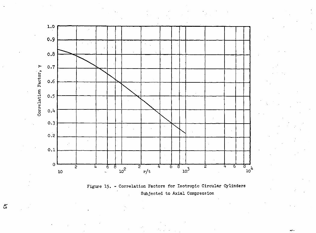
Correlation Factors
The correlation factor Y is a term used to account for the differences
between theoretical buckling analysis and experiment. For isotropic circular
cylinders subjected to axial compression the recommended correlation factor
(Ref. 11) may be computed by the expression:
11
Y = 1 - .901 (1 -
where
(1)
(2)
Equation (l) is presented graphically in Figure 15 for isotropic cylinders.
For multilayered orthotropic cylinders the correlation factor is of the
same form as equation (l) and <f> is replaced by
.V2
293 4 rmr (3)
Equation (3) reduces to (2) if the material is considered to be homogeneous.
The correlation factors for all specimens were calculated assuming the
material to be isotropic, equation (2), and compared to the actual ortho-
tropic nonhomogeneous material case equation (3). The difference between
the two cases was less than 2 percent. This is due primarily to the
radical in equation (3) which is insensitive to the inhomogeneity of the
cylinder wall for the particular laminates studied herein.
End Design for Stability Critical Composite Cylinders
Subjected to Axial Compressive Loading
Reinforcement to prevent brooming failures consisted of adding circumferential
fiberglass doublers cured on the outside surface of the cylinder and fitting the in-
side of the specimen with an epoxy potting compound to a depth of 1.3 cm (0.5 in.)
on each end. To obtain buckling failures away from the ends of the speci-
mens additional 0 rad (0°) plies of boron-epoxy were added internal to the
laminate. These plies are necessary to reduce the local bending stresses
which result from the end support .and rotational restraints. The required
number and length of the reinforcement plies were determined by consider-
ing the cylinder to be loaded in axial compression (see Figure l£(a)), with

the ends assumed completely restrained from radial displacement and rotation.
The local bending moment resulting from the restraint is rapidly damped out
and the length of the transition region, 1. , between the built in edge and
the basic cylinder as given by article 11.1 of Reference 12. is
1 ~ — (L.)tr p
where p is the characteristic of the basic cylinder and for orthotropic
material was derived to be equal to
p = \ I *22* (5)
To prevent any bending failure in this transition region additional
unidirectional boron-epoxy plies are added to the basic laminate to obtain
a minimum margin of safety of 15 percent. For preliminary design the max-
imum required transition thickness tn was determined using the basic cylinderi\parameters as follows :
F = f + fall membrane bending
A + MoYiEi
where F , , = Allowable stress in cylinder wallallY. = Distance 'from -the neutral axis of the laminate to the i layer
4*T"iE. =. Modulus of the i layer in the longitudinal direction
(M is the maximum bending moment at the assumed built in edge of
the cylinder shown in Figure l6(b).)
13

Substituting equation (?) into (6) and solving for the required
transition thickness tR including a 15 percent margin of safety results
in
> N E.
R ' Fall i 12 EI;L . 1]L
where F ...j = 250 ksi for unidirectional boron-epoxy and 119 ksi for
Ti-6Al-UVand _ _
N = v (N )x 'cal x cal
The required number of unidirectional boron-epoxy reinforcement plies,
based on a nominal per -ply thickness of 0.0130 cm (.0051 in.) is obtained
from
No. of plies =
where the units of t., and t are centimeters.K
Having determined the preliminary required thickness for the transition
region, the applied load distribution near the ends of the cylinders was cal-
culated using the basic method of analysis presented by Wittrick (Ref. 13).
Wittrick presents a solution for the internal shear load and wall bending
moment distributions in an isotropic cylindrical tube subjected to internal
pressure and a uniform tensile axial load. The cylinder is assumed re-
strained at the ends. Wittrick's solution was extended to include orthotropic
material and shown to be valid for axial compression loads smaller than the
classical symmetrical buckling load of the cylinder.
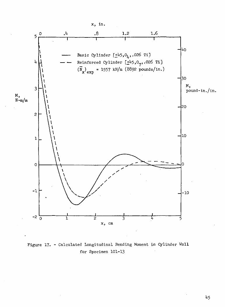
A typical longitudinal bending moment distribution calculated using
Wittrickfe modified analysis is shown in Figure 17 for specimen 101-13. The
two curves shown in the figure were obtained using the basic and the rein-
forced cylinder parameters. All calculations were performed assuming the
cylinder to be continuous, and no attempt was made to couple the basic
cylinder laminate with the reinforced ends. The structural integrity of
the end reinforcements was checked using the extreme values of bending
moment from each curve. For analysis the datum or end of the cylinder was
conservatively chosen at the beginning of the fiberglass tab (see Figure 16)

COMPARISON OF TEST DATA WITH ANALYSIS
Experimental! and calculated buckling strengths, correlation factors,
and elastic mod-oil are presented in Table IV for all specimens. The agree-
ment between experimental correlation factors and the calculated values is
reasonable. A cosmparison of calculated and experimental correlation factors
for all specimens is shown in Figure 18. Six of the eight specimens exceeded
the recommended values of the calculated correlation factors. The two speci-
mens which had lower than anticipated experimental loads are 101-11 and 100-
lla No. 2. A failure analysis of specimen 101-11 indicated an insufficient
number of reinforcement plies were added to the laminate to prevent local
end buckling and material failure. The stress in the titanium at the end
of the specimen exceeded the compression proportional limit, and initiated
the failure. Figure 12(e) shows an end view of the failed specimen with the
titanium bearing surface completely rolled over.
A comparison of the calculated and experimental elastic moduli pre-
sented in Table .IV shows good agreement for all of the specimens with a
maximum discrepancy of less than 3 percent.
CONCLUDING REMARKS
Correlation between theoretical and experimental compression buckling
loads for boron-epoxy composite and boron-epoxy reinforced titanium cylinders
having diameter ito thickness ratios between hO and 70 have been determined.
The experimental correlation factors are in good agreement with the correla-
tion factors ccerputed for multilayered orthotropic cylinders from the equa-
tions presented in the literature. For the cylinders tested in this invest-
igation the correlation between experiment and theory ranged from 0.73 to
0.97. Calculated buckling strengths were determined using three different
shell theories. Buckling strengths predicted with the Donnell theory differed
from those predicted using Flugge's and Sanders' shell theories by as much
as 6k percent. Buckling failures away from the specimen ends were obtained
by locally reinforcing both ends with unidirectional plies of boron-epoxy
added internal to the laminate. The longitudinal bending moment distribu-
15
tion at the ends of the specimens was obtained using a solution proposed by
Wittrick, and extended to include orthotropic materials. Based on the
experimental results, the analysis was shown to applicable for end design
of composite cylinders subjected to compressive loading.
16

APPENDIX A
CONVERSION OF U.S. CUSTOMARY UNITS TO SI UNITS
The International System of Units (Si) was adopted by the Eleventh
General Conference on Weights and Measures, Paris, October I960, in Resolu-
tion No. 12. (See ref. 7.) Conversion factors for the units used herein
are given in the following tables:
Physical Quantity
Angle
Bending Moment
Area
Force
Length
Moduli and Stress
Temperature
Unit Loading
U.S. CustomaryUnit
Degrees
kip- in.
in2
kip = 1000 Ibf
in.
ksi = kips/in
(6F + 459.67)
Ib/in
Convers ionFactor(*)
1.7 5 x 10²
1.130 x 10²
6. 1*52 x 10
kMQ x 103
2.5U x 102
6.895 x 10⁶
5/91.751 x 102
SI Unit
Radians (rad)
Newton -Meters (N-m)2
Square Meters (m )
Newtons (N)
Meters (m)
Newtons Per SquareMeter (N/m2)
Degrees Kelvin (K)
Newtons Per Meter(N/m)
* Multiply value given in U.S. Customary Unit by conversion factor to obtain
equivalent value in SI Unit.
Prefixes to indicate multiple of units are as follows:
Prefix
milli (m)
centi (c)
kilo (k)
giga (G)
Multiple
Kf3.
io"2
103
IO9
17

APPENDIX B
CURE CYCLE FOR BORON-EPOXY-COMPOSITE CYLINDERS
1. Place part in autoclave and draw 20 inch vacuum minimum.n
2. Using CO , apply 0.62-0.66 GN/m (90-95 psi) pressure.
3. Check vacuum system, turn vacuum off and measure fall off. If sys-o
tern does not maintain 34 kN/m (10 inches of Hg) after 60 sec. (1
minute), open door and replace hoses and check bag.
P4. After system passes leakage test reduce vacuum to 6.8 kN/m (2 inches
of Hg) and heat tube to 339-356 K (!50-l80°F) at 0.62-0.66 GN/m2 (90-
95 psi) pressure. % •
5. Hold system pressure, temperature, and vacuum of step 4 for 1.8-2.7k
sec. (30- 5 minutes).
6. Heat part from 339-356 K (l50-l80°F) to 444-1*56 K (340-36o°F) in
1.8-2.7k sec. (30-45 minutes).
7. At 381 K (225°F), drop pressure to 0.48 + 0.04 kN/m2 (70 + 5 psi).
8. Hold 450 + 6 K (350° ± 10°F), 0.48 + 0.04 kN/m2 (70 + 5 psi), and
6.8 kN/m2 (2 inches of Hg) for 5.4 + 0.3k sec. (90+5 minutes).
9. Cool to 325-333 K (125-l40°F) in not less than 2.7k sec. (45 minutes).
10. Apply full vacuum, -release pressure and remove from autoclave.
11. Post cure in air circulating oven at 464 _Q K (375 _ °F) for 10.8 +
0.6k sec. (180 + 10 minutes) after removing all bleeders. Heat up
time to 464 K (375 Q0*1) i-s that of oven set at 464-469 K (375-
385°F).

APPENDIX C ..
CURE CYCLE FOR BORON-EPOXY-COMPOSITE-REINFORCED
TITANIUM CYLINDERS
1. After bagging, cover assembly with asbestos. .2
2. Apply 68 kN/m (20 inches of Hg) vacuum (minimum) and install part
in autoclave.
3. Heat laminate to a temperature of 339 + 1? K (150 + 30°F) while2
maintaining 68 kN/m (20 inches of Hg).o
k. Pressurize to .3^ +_ .Ok kN/m (50 + 5 psi) with CO .
5i Check bag for leaks. Turn vacuum system off. If part does not maintain2
.3 kN/m (10 inches of Hg) vacuum after 60 sec (l minute), check bag
and vacuum system. . '
6. Vent bag to atmosphere using C0?, reducing vacuum to a maximum of
6.8 kN/m2 (2 inches of Hg).
•ffi7. Heat laminate to 444 _ K (340 "F) within 1.6-2.4k sec. (40-60
minutes). .
8. Maintain laminate at a temperature of 444 K (340 _ °F) and a pres-
sure of .34 + .04 kN/m2 (50 + 5 psi) for 5.4 + 0.3 k sec. (90 5 min-
utes ). •
9. Cool to 356 K (180°F) in not less than 2.4k sec. (40 minutes). Draw
68 kN/m (20 inches of Hg) before releasing autoclave pressure. Re-
move laminate from autoclave. .
10. Post cure in air circulating oven at 464 K (375 _ Q°F) for 10.8 +
0.6k sec. (180 ± 10 minutes) after removing all bleeders. Suspend
vertically with thermocouples on part as applicable. Heat-up time to
temperature is that of oven set at 464-469 .K (375-385°F).

Page Intentionally Left Blank

REFERENCES
1. <Zender, George W.; and Dexter, H. Benson: Compressive Properties
and Column Efficiency of Metals Reinforced on the Surface With
Bonded Filaments. NASA TN D-48?8, 1968.
2. Dexter, H. Benson: Compressive and Column Strengths of Aluminum
Tubing With Various Amounts of Unidirectional Boron/Epoxy Reinforce-
ment. NASA TN D-5938, 1970.
3. Corvelli, Nicholas; and Carri, Robert: Evaluation of Boron-Epoxy-
Reinforced Titanium Tubular Truss for Application to a Space Shuttle
Booster Thrust Structure. NASA TN D-6778, 1972.
k. Sicari, J. et al.: Fabrication of 1/3 Scale Boron/Epoxy Booster
Thrust Structure. Phase I Final Report, Prepared by Grumman Aerospace
Corporation for NASA Marshall Space Flight Center under NASA Contract
.No. NAS8-26675, Sept. 1971.
5. Card, Michael F.: Experiments to Determine the Strength of Filament-
. :., , Wound Cylinders Loaded in Axial Compression. NASA TN D-3522, 1966.
6. Dow, Norris F.; and Rosen, B. Walter: Structural Efficiency of
Orthotropic Cylindrical Shells Subjected to Axial Compression. AIAA
J. Vol. U, No. 3, Mar. 1966, pp. U81-U85.
.7. Comm. on Metric Pract.: ASTM Metric Practice Guide. NBS Handbook 102,
U.S. Dep. Com., Mar. 10, 1967.
8. Hoff, N.J.: The Accuracy of Donnell's Equations. J. Appl. Mech.,
Vol. 22, Sept. 1955. .
9- Wu, C.H.: Buckling of Anisotropic Circular Cylindrical Shells. .
Ph. D. Thesis, Dept. of Solid Mech. Structures and Mech. Design,
Case Western Reserve University, June 1971.
10. Anderson, M.S.; Fulton, R.E.; Heard, W.L. Jr. and Walz, J.E.:
Stress, Buckling, and Vibration Analysis of Shells of Revolution.
Computers and Structures, Vol. 1, pp. 157-192. Pergamon Press 1971.
Printed in Great Britain.
11. Anon.: Buckling of Thin-Walled Circular Cylinders. NASA SP-8007,
1965. (Revised 1968.) . - ; '
21

REFERENCES (Cont.)
12. Timoshenko, Stephen P.; and Gere, James M.: Theory of Elastic
Stability. Second ed., McGraw-Hill Book Co., C. 1961.
13. Wittrick, W.H., Interaction Between Membrane and Edge Stresses
for Thin Cylinders Under Axially Symmetric Loading. R.A.S.J.,
Vol. 67, Mar. 1963.
22

<u c Rg o
cr-4
O
fiO
PQMOc•r6oC•HEocO•H-Pds•H<Hc0OcO)
6•HOP(
CO
0 O
0 0
l-l r-1
CO
CO
ON
ON
00 C
O
ITN ir\
VD
VO
co co
|ii t- t>
-C
M
CM
•
•
o\o
\
co
co
CM
C
M1
*
*
CO
CO
r-l r-l
co co-
J" —
Hf
• *
vo vo
1 — 1
cvITN
ooON9
\
IfN
qj"loO
N•»IfNoIfN
arH C
M
0 0
^ S
5
O
oji-l r-<•H
rH
1
1Oo
0 0
o o
r-l r-l
r-l r4
LT\
IfN
VD
VO
co co
CM
CMC
O C
O•
•O
\ON
o o
CO
CO
•
•
XX
*-t~
vo voC
M
CM
-3- -H
-
i — i
l/N^j
+JJ-
O
CMOO
N«\
_j-
OLA
aoi
co cor-l r-t1
1
£^
r-l
co»
ITN
VOt*LcoIfN
COCO
COr>-•
ON8r-l
Or-t•
COco£-
1
1
•rl
EH
VO81•v
\n"HOt/N
I — i
r-<r-l|i-l
O
CO*
VDCMUN
CMC
OCOO
•
ON
Oo•
ITNr-l
0r-1*
COcoEH
i — i
•rl
EH
VOCMO1
**b-
OITN
' *
0)r-lr-l1
vo vo•
«
ir\ ir\
CO
CO
t- t--vo vo
SoCO
co co
co cot**
C*""•
•O
N O
N
800
•
*IfN
ITN
i-H
r-l
o o
r-l r-l
•
•C
O C
Oco co
EHi —
i•HEH
VOCMO
*\
-3"
O^
ITN
1 — i
Si
CO
CO
r-l r-t1
1r-lOr-l
23

i-qi5Kpqfi
CO
X
-HO
-P
ft $H
1
ft
C
0O
h
5s PL,
Op^ £>^
if\ P
L,
0IfN
1ITN(U
i —
1-P
W
)•H
C
FO
*»H
•rH
CO
•HPC;
oLT\
[+1
•O03(-1
ir\C
O,o+ 1, —
..o§T303f-i
t-IfN•r-l
^—
OOT303
O
^>
j t
•Sn0)
0p[
^_^
t
^ ^ ^
VO
V
O
CM
VO
V
O
J"
ITN
IT
NCM
C
M
CO
IT\
IT\- —
^
^-^
C
O C
O•
•C
O
CO
C
O
O
Or-l
r-l IT
N
^ "o
"o
o
--^
0
0
O V
OO
S
CXI
CM
C
M
OCM
-ro t—
C
M
u^•
-x *-^
O
C
M
O
r-l
lf\ O
O
CM
C
MCM
^ —
s.
0
^~-
O
O
'-^o
o
o
vo
CM
O\
CM
O
C
MO
O
CM
t-
LPv
CM
^-s
-^
—
CM
O
r-l O
IT
V
O
OCM
CM
CM
X
N
r-lLTN0OCD
OJ
ror-lOO
•Hto
CMg0CO
x-^pi
*-^ C
r-l -H
-rl
3
CO
"0
*1
0
—
GS
-~
-
0C
M
-r- 1
C
S
co ->
O
~->
Ai
to•H
S
tO
w
O
O
O
0)
tO
CM
T
-l -H
d
O
*\
0
4-3
4-J
,X
J-i W
^~^
03 03
Oft
0
S
PS
P
S
-rl6
r-l
0
X!
O
3
co
to
EH
O
t3
•>O
C
O
C
G
fnH
2
2
O
O
0)
03 r—
1 tO
C
O
>jC
<L>
Pi W
W
O
S•H
W
T
J
-H
-H
hP
-O
fn
O
O
O3
<!J
S
PL,
PW
C
D-P
>
W
)•rl
CO
f-(
J-i !H
03
hO
C
03
O
O
fnC
O
i d)
1-3
C
CU
O
^
XI
OS
-H
>
i-P
EH
C
O
S
S
"
•a0r-l03£^
.§_§:11-1V
O•H03
•HEH
O
«--0
O
x-.
o
ir\ cr\
VO
r-l
r-lr-l
VO
r-l
^^S
*
S
N
^
O
CM
r-l
r—l
-H;
CM
r-l C
O•Hto
^f.
CMs§rv
4_3•Hg
y—
*r3•r-l
x —
s H
pto
-i-iA
J
W
rHA
! 03
— •
CCM
O
S
CM
-H
^
*"-
^H
O
S
OO
ft
-> o
to h
pi to
P
H
p!
r-l C
•D
3
OO
T
3
-HS
0
co
S
wtO
0)
bO
(H
!-<§
a3 ft
a; g
O
XI
O^
CO
O
s00
IA
VDIA
O
t\JCM
*-*
O
Cy
'
rXS
8
OJ
OJ
OJ
OJ
OONO
JmONO
CJ
VO
-3
OJ
CO
ON
IaI
o.XCJ
i-4W
t-(O0r-lE
d
>
«
&
>
01
05
'5** 0IS*.
&
J3
?BE:OC
],K
~es:0
r-4S)
U3OXz^>VXa
c•HW43
JtJCwrHsXc•f-ieCJ
iHJ113)Q
0«OJ
COr-l
OrHOJ
O<MON
f:tTv
C--
lAS•s&fX,8CO
-3-
»IT\
OJ
sCTi
OfHmcvr-<0Kdr-li-(1Oor-4
air\
SOJ
orH2SC\J
ON
p:ITS
t-
ir\
18,^ON
r-4
OJ-ITv
ITS
-4"
OJ
ssrocycug5r-41
oVO£iOJ
f-r-4
s»CJ
CO
u-\
^rooo
CO
COS1
rH888rou-\f-
r-l
t-
O-3-
i-(C
Oi-t
3§
RSOJ
CO
r-t
Ooo
«CJ
mir»t*-
S;»-)r-l
ON
ON
OOJ
l-tt--ir\r-l
8OJ
-*r-Ht-
OJ-
r-I00i~i
a>mr-f1
RJ-lAC\J
\0r-l
8rnLTNO
J
-d-
O\
t-
rnt*-
u~\
\RCOOJ
OJ
ooir\
j-COt^ooVDrnITN
OJ
s-*O«r-<M1
r-<
s
oot»OJ
OJ
t~-r-t
Om-a-OJ
OJ
ir\
IAC^
Po0?
^OJ
-rj-coO
J
of:^>HOJ
OJ
s&1dr-lr-l1
O\D8OJ
Or-t
1C-
rnPif-iCO
«ON
SVDs>-§t-UN
ITN
r-l
V£)
VT5LA0COro
J-r^rnHi•HS
fCocOJ
COr-4
1c-rn~^«ON
S\D»i-4rnrnON
IAj-r-l
vo\oLA0COrn_^•~tdrnr-41
S[c.
c0)E'oVa.oaEouXOavIoo034)3

•oo55.?
5°
S.o
**. inP
o co
U.Q
0§<JvaME3'coi-o41OcVKOa.atcOoCOIu3O>
»a.

SteelFemale Mold Form
Aluminum-.Layup Mandrel
I X V\\X\\XXV\VVV\\XXXXX XXN
Nylon Peel Plies
•Fiber-glass BleederPlies
•Boron-EpoxyPrepreg Lay-up
-Nylon FilmVacuum Bag
Figure 3. - Cross Section of Layup for All-Composite Cylinders
"Pagermissing from available version"
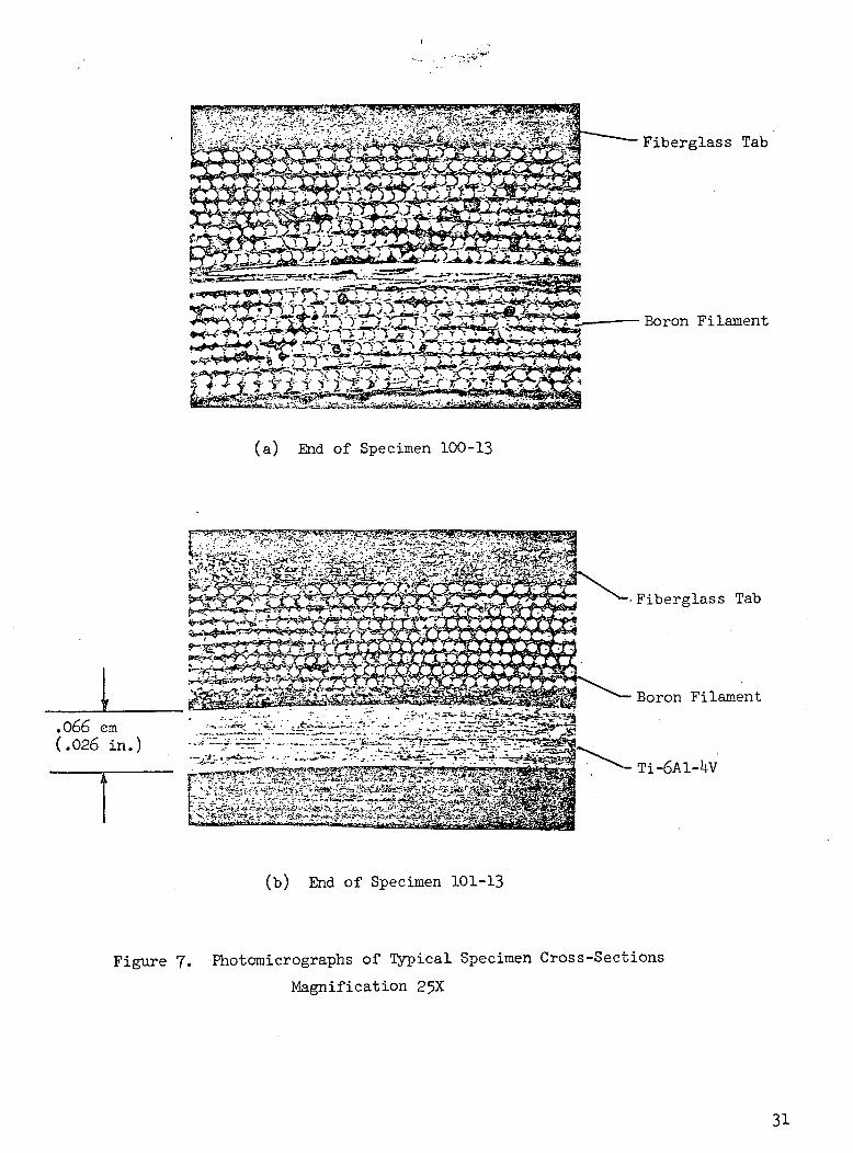
(a) End of Specimen 100-13
73P
.066 em(.026 in.)
Fiberglass Tab
Boron Filament
Fiberglass Tab
Boron Filament
(b) End of Specimen 101-13
Figure 7. Photomicrographs of Typical Specimen Cross-Sections
Magnification 25X
31

Hardened Steel Disk
"V
, ,, . .. .
?* V-^-';-1**." '•"' ' ''-" i^-'fi'^HlQ "^ f1" **™*
fr? .:;T.;.r ;"->^ ;i >** v,\:i *•:' -V;V- ^rTt ' ^**-*^?s- y~- -A ^^Mfr-;-i4^AKSa^..•v v - •:;• •;' •»*&# ^?fc
**-:
II
i • • '-.^tr^-^;-:jM"i :v^-^:.-^*-xt»iL,^*?s>wr?;'»'"V vjrf -f••-'?!'"v.'"•':"";:- •;-S--f':. ;;w.j,-,aij. K -'*•"•'.".- .•'"='•-'-'• , ' . -"V-- ' ' "..v^SQS .
feS-&W ^S^Si Mfi-^'^^'l v--.ViV-x: n*^?X'--:li\ te f^ ' ^^ te^^^ - " •gC?}«|:rf%^^;/Ji f : ifM::fcrf ^Ef ':"'.:
Figure 8. - Compression Test Setup

B
29.
- c rr-r- D r
19
1
-Xc5
3,20
B
—X.
HOTE: All gages are axial except
19 and 20 which measure
transverse strains12
Sect. C-C
Sect. E-E
30 25
Sect. D-D
Sect. F-F
Specimen
100 -lla
100-13
100-13a
101-11
101-lla
101-13
101-13a
Dimension
Xlcm
3.81
2.5^
2.5^
2.5^
in
1.50
1.00
1.00
1.00
X2cm
5.593.303.813.30U.063.303.81
in
2.20
1.30
1.50
1.30
1.60
1.30
1.50
X3cm
6.99
6.10
6.35
5.8U
in
2.75
2.1*0
2.50
2.30
X4cm
10. l£
8.38
8.6U
7.62
in
U.oo-
3-30
3.^0
3.00
x.cm
5.593.303.813.30U.o6
3.303.81
in
2.20
1.30
1.50
1.30
1.60
1.30
1.50
Figure 9« ~ Location and Identification of Strain Gages
33

wftoCO
o
COCM
ooVD
OOOOCVJ
oCVJ
wftPH
OCOO
ooCO
oovooo
ooCM
3oCOooOoooCMOO3o00ooooCMOO
03
oo0S-3O-P
0
CO
ftC
O
C•H05ctf
-PCO
CMOJ
ooc0e•HO0P(
CO0)
VI
G0S•Ho0ftCO-PCO0tH
coCOcSO0M-PCOO-p
I *
O
0C
J
<M
e (S
5JH
CO0
o>OC•HODOI
•s
G)0
.H
Sd
O
o
o•H
K
I•
s0g,
C•H
-CoACO

a•i-icdco
05r-lHI
r-l
soOJ
CO
0)3G•H-PCOo
r-lr-JI
OSo<uCO
sGJ^l35

600
koo -
p,kN
200 -
- 120
0 ..002 .00*4. .006 .008 .010
(e) Specimen 101-13a
Figure 10. - Concluded
36

0500
400 -
300Load,kN
200 -
100
0
Shortening, in.
.02 .Oh .06 .08
.5
- 100
1.0 1.5 2.0 2.5 3.0
Shortening, mm
Figure 11. - Load-Shortening Curve For Specimen 101-13a
37

c^.4
•fe«v< S -'5-v /i' V y*ftf-"Sa -aH /--.SLi'Jfc '";'v.-*' •'7hi" i^rpIC^^
plgw^al'S^%t;%^ -V.r:-: ;-VV |4 W«:2«^----^ '>-(m
• ^ ^ »^ :.: • -\a^;^^^^^^^^;-;:c;P'i;'pS^
(a) Specimen 100-lla No, 2
Figure 12. - Typical Local Buckling Failures
A>v.v,-?->fc5??3I?:-•'?.>»••"•?$'•'-•''-': • •• «v '£&
£>;'tSs?»rr.: ir. * rf-i i* j =.-t'
(b) Specimens 101-11 101-13 100-13
(c) Specimens 100-llaNo. 1
100-llaNo. 2
100-13a
Figure 12. - Continued
39
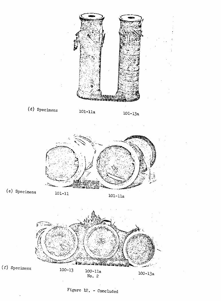
Figure y - Concluded
6000
5000
N ,xkN/im
Uooo
3000
C"elected design for specimen 100-lla± 5,05,90,±U5,90,0 +1*5]
t = 0.2332 cm (0.0918 in.)
Maximum compressivestrength envelope
11.10
Percent1.57 rad (90°) layers
I
22.1
I
50 60 70
Percent Axial Layers
80
30
X
kips/in.
20
90
Figure 13. - Laminate Optimization Study

Tangent Modulus, ksi
1.2
1.0
, .8
0
.6Stress,GN/m2
.2
0
Uooo 8000 12000
I20 kO 60
Tangent Modulus,
802
16000
160
120
Stress,ksi
80
100 120
Figure Compressive Tangent Modulus For Annealed Ti
6A1-UV Alloy Sheet at Room Temperature
3or5
»-o
r/t2
10
OJs
CA•
O
CO•O
t— •O
VQ•O
m•
O
J-•
O
ro•O
cvj'
•O
H•
O
COt-iCircularFactors
CO•HCOto0>fn&O•HP
iO
O
h
O
° tico
siM
-HX
O
"^<4H
O•O0)
•pt>a)•l~3
a •§
O
CQ
•H•PAVflooIir\

'Fiber-glass tabs on O.D.Potting inside cylinder
(a) Loading
M r*~ — *10 1 '
*vo
For Analysis -" ^
VN /T^_ y
t
i— - r
N^ *"' x
-t N^ »- x
o t.R
(b) Applied end loads and sign convention
Figure 16. - Cylinder Loading and Applied End Loads
x, in.
.8 1.2 1.6T
Basic Cylinder f± 5,0 ,.026 Til
Reinforced Cylinder [+U5,0 ,.026 Ti]
(N ) = 1557 kN/m (8892 pounds/in.)
N-m/m
0
30
M,pound-in./in.
20
10
0
-10
Figure 17. - Calculated Longitudinal Bending Moment in Cylinder Wall
for Specimen 101-13

i-iHt
OJ
Hr-lIOO
IOO
aaiHIHs
03
21
I
Or-l
CO
U
H
CO
O•POerf
g
OJ
0>OO
OOInOO-POOjCO•rH-PCtfr-lQJf-H>HOO03•P1•H!n0)
§T!
-POtrfOOw•HI00r-H0)
•Hh
WCO0)ftCO•PCO
EHtiOCJ
pq


![Thermal conductivity and structure of non-covalent ... · PDF fileThermal conductivity and structure of non-covalent functionalized graphene/epoxy composites ... boron nitride [5],](https://img.pdfslide.us/doc/110x75/5aa175147f8b9a07758b9e5b/thermal-conductivity-and-structure-of-non-covalent-conductivity-and-structure.jpg)