Embed Size (px)
Citation preview

AlllOl fiflMTbD
AlllDM ^37aflS
]\«/^r[OWAL :EORE/iU
0E STANDARDS liB'RARy; ' .
MlM. ;i> .flilK&BOftl ;Sil
:|S4iS«l¥iElEI


I
j
t

Ncticnal Pursau ot '^rsnaaros
AUG 1 9 1952
U. S. DEPARTMENT OF COMMERCE NATIONAL BUREAU OF STANDARDS
SUPPLEMENT TO SCREW-THREAD STANDARDS
FOR FEDERAL SERVICES 1944
Supplement to Handbook H28 (1944)
National Bureau of Standards
AUG 17 1359
QCi .U5i

NITED STATES DEPARTMENT OF COMMERCE • • • Charles Sawyer, Secretary
NATIONAL BUREAU OF STANDARDS • E. U. Condon, Dwf/or
SUPPLEMENT TO NATIONAL BUREAU OF STANDARDS HANDBOOK H28 (1944)
SUPPLEMENT TO
SCREW-THREAD STANDARDS
FOR FEDERAL SERVICES
1944
Prepared by direction of the
Interdepartmental Screw-Thread Committee
[Issued June 15, 1949]
\
UNITED STATES GOVERNMENT PRINTING OFFICE, WASHINGTON : 1949
sale by the Superintendent of Documents, U. S. Government Printing Office, Washington 25, D. C. Price 25 cents

Foreword
An extensive revision of the 1944 edition of Handbook H28, Screw Thread Stand¬ ards for Federal Services, is in process, contingent on international standardization and
the development of screw-tlnead standards, pipe-thread standards, and screw, bolt, and nut standards by Sectional Committees Bl, B2, and Bl8 of the American Standards
Association. On account of the uncompleted status of much of this work, publication
of a revised edition of Handbook H28 is being deferred. Revisions and additions that are completed are being published now in order to
avoid undue delay in putting them into effect in departments of the Federal Government.
This Supplement, which is arranged to correspond to the 1944 edition, is issued for that
purpose.
E. U. Condon, Chairman. n
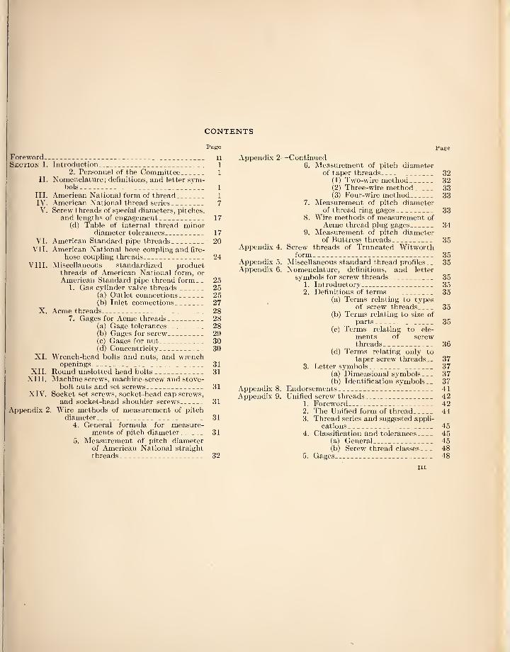
CONTENTS
Page
Foreword_ ii Section I. Introduction_ 1
2. Personnel of the Committee_ 1 II. Nomenclature; definitions, and letter sjmi- bols_ 1
III. American National form of thread_ 1 IV. American National thread series_ 7 V. Screw threads of special diameters, pitches,
and lengths of engagement_ 17 (d) Table of internal thread minor
diameter tolerances_ 17 VI. American Standard pipe threads_ 20
VII. American National hose coupling and fire¬ hose coupling threads_ 24
VIII. Miscellaneous standardized product threads of American National form, or American Standard pipe thread form__ 25
1. Gas cylinder valve threads_ 25 (a) Outlet connections_ 25 (b) Inlet connections_ 27
X. Acme threads_ 28 7. Gages for Acme threads_ 28
(a) Gage tolerances_ 28 (b) Gages for screw_ 29 (c) Gages for nut_ 30 (d) Concentricity_ 30
XI. Wrench-head bolts and nuts, and wrench openings_ 31
XII. Round unslotted head bolts_ 31 XIII. Machine screws, machine-screw and stove-
bolt nuts and set screws_ 31 XIV. Socket set screws, socket-head cap screws,
and socket-head shoulder screws_ 31 Appendix 2. Wire methods of measurement of pitch
diameter_ 31 4. General formula for measure¬
ments of pitch diameter_ 31 5. Measurement of pitch diameter
of American National straight threads_ 32
Page
Appendix 2—Continued 6. Aleasurement of pitch diameter
of taper threads_ 32 (1) Two-wire method_ 32 (2) Three-wire method_ 33 (3) Four-wire method_ 33
7. Measurement of pitch diameter of thread ring gages_ 33
8. Wire methods of measurement of Acme thread plug gages_ 34
9. Measurement of pitch diameter of Buttress threads_ 35
Appendix 4. Screw threads of Truncated Witworth form_ 35
Appendix 5. Miscellaneous standard thread profiles^- 35 Appendix 6. Nomenclature, definitions, and letter
symbols for screw threads_ 35 1. Introductory_ 35 2. Definitions of terms_ 35
(a) Terms relating to types of screw threads_ 35
(b) Terms relating to size of parts_ 35
(c) Terms relating to ele¬ ments of screw threads_ 36
(d) Terms relating only to taper screw threads. _ 37
3. Letter symbols_ 37 (a) Dimensional symbols_ 37 (b) Identification symbols __ 37
Appendix 8. Endorsements_ 41 Appendix 9. Unified screw threads_ 42
1. Foreword_ 42 2. The Unified form of thread_ 44 3. Thread series and suggested appli¬
cations _ 45 4. Classification and tolerances_ 45
(a) General_ 45 (b) Screw thread classes_ 48
5. Gages_ 48
III
APPROVAL BY
THE SECRETARIES OF DEFENSE AND COMMERCE AND THE SECRETARIES OF THE DEPARTMENTS OF
THE ARMY, NAVY, AND AIR FORCE
The accompanying supplement to Handbook H28 (1944) on screw-thread standards for Federal Services, submitted by the In¬ terdepartmental Screw Thread Committee, is hereby approved, and the use of these standards by the National Military Establishment and the Department of Commerce, except where a need for deviation therefrom is shown, is hereby ordered.
James Forrestal,
Secretary of Defense.
Charles Sawyer,
Secretary of Commerce.
Kenneth Royall,
Secretary, Department of the Army.
John L. Sullivan,
Secretary, Department of the Navy.
W. Stuart Symington,
Secretary, Department of the Air Force.
IV

SUPPLEMENT TO SCREW-THREAD STANDARDS FOR
FEDERAL SERVICES 1944
SECTION I. INTRODUCTION
Page 1, revise the second division of this section as follows:
2. PERSONNEL OF THE COMMITTEE
The personnel of the Interdepartmental Screw Thread Committee is as follows:
Representing the Department of the Army: Me. Stanley Fahrow, Industrial Division, Ordnance
Department, National Defense Building, Washington 25, D. C.
Mr. Eugene Von Loesch, Research and Development Division, Corps of Engineers, Room 2422, Building T-7, Gravelly Point, Virginia.
Representing the Department of the Navy: Mr. Karl D. Williams, Bureau of Ships (Code 350),
Department of the Navy, Washington 25, D. C. Mr. Burton H. Slocum, Research and Development
Division, Bureau of Ordnance, Department of the Navy, Washington 25, D. C.
Representing the Department of the Air Force: Mr. Arthur F. Wentzel. Air Material Command,
MCREXU—Engineering Standards Section, Engi¬ neering Division, Wright-Patterson Air Force Base, Dayton, Ohio.
Mr. Frank E. Richardson, Headquarters, U. S. Air Force, Research and Development Division, Na¬ tional Defense Building, Washington 25, D. C.
Representing the Department of Commerce: Dr. Edward U. Condon, Chairman, Director, National
Bureau of Standards, Washington 25, D. C. Mr. David R. Miller, Gage Section, Metrology Div¬
ision, National Bureau of Standards, Washington 25, D. C.
Mr. Irvin H. Fullmer, Secretary and Alternate, Gage Section, National Bureau of Standards, Washington 25, D. C.
Liaison Representatives of Sectional Committees Organized Under the Procedure of the American Standards Asso¬ ciation:
Me. P. M. Delzell, Chief of Gage Division, Ford Motor Company, Dearborn, Michigan. (Member of ASA Committee Bl.)
Mr. H. C. Erdman, Technical Asst, to Vice-Pres., The National Screw & Manufacturing Co., Cleveland, Ohio. (Member of ASA Committees Bl and B18.)
Mr. H. W. Robb, Standards Division, General Electric Co., Schenectady, N. Y. (Member of ASA Committees Bl and B18.)
Me. Paul G. Schulz, Development Engineer, Valve & Fitting Engineering Department, Crane Co., Chicago, Ill. (Member of ASA Committees Bl and B2.)
Mr. Wm. C. Stewart, Technical Adviser, American Insti¬ tute of Bolt, Nut, & Rivet Manufacturers, Cleveland, Ohio. (Member of ASA Committees Bl and B18.)
SECTION II. NOMENCLATURE, DEFINI¬
TIONS, AND LETTER SYMBOLS
A tentative revision of this section, based on a proposed American Standard for “Nomenclature, Definitions, and Letter Symbols for ScrewThreads”
is given herein as a revised appendix 6. After pos¬ sible further revision, it is expected that this ap¬ pendix will be published as section II of the next edition of this Handbook.
SECTION III. AMERICAN NATIONAL
FORM OF THREAD
The following corrections and revisions are to be inserted:
Page 7, table 1, col. 15, change “.09622” to “.09623.”
Pages 9 and 13, Figures 4 and 7, change “2Xp. d. tol. on radius” to “tolerance on
MAJOR DIAMETER OF SCREW IS TWICE THE TOLER¬
ANCE ON PITCH DIAMETER.”
Pages 9, 13, 16, 19, Figures 4, 7, 10, 13, change “tables 7 to 16, inclusive” to “tables 16, 24, ETC.”
Pages 19 to 23. Delete class 4 here and wher¬ ever it appears elsewhere.
Pages 23 to 28. 5. Class 5 Fit.—
The following is a resolution agreed upon by a subcommittee of the Interdepartmental Screw Tliread Committee, Mr. W. S. Brown, chairman, (American Locomotive Co., Schenectady, N. Y.), appointed to investigate the class 5 fit:
In view of the well-recognized fact that figures for pitch diameter tolerances for interference thread fits, published in the 1944 edition of the H28 Handbook, have not produced an all-round satisfactory solution to the difficulties inherent in the older “Tentative Class 5” and have not been widely accepted commer¬ cially; and in view of the large amount of work neces¬ sary to produce some possibly improved system of tol¬ erances, it is the opinion of this subcommittee that the status shown in the H28 {1942) Handbook be restored. This includes the “Tentative Class 5" and the “Alterna¬ tive Class 5" Tolerances and. comments relative to gaging. This restoration would stand until a further investiga¬ tion of the whole subject can be made. The desired result might be achieved by republication in the forth¬ coming supplement to the H28 Handbook. Additional notes could explain the reason for the reinstatement.
The subcommittee further is of the opinion that po¬ tential difficulties of moderate lead error are probably minimized by effects produced during mating of the studs and tapped holes. Thus, pitch diameter should be measured directly across opposing threads and grooves, that is, not by ring gage. Lead error should be checked by independent means to prevent mating of parts with excessive amounts.
The following discussion of interference thread fits was also submitted by the chahman of the sub¬ committee:
It is recognized, from the outset, that the problem of producing and mating external and internal compo¬ nents of interference thread fits involves so many vari-
1

2 Handbooks of the National Bureau of Standards
ahles that, in the present state of the mechanical arts, it is virttially impossible to set up standards which will satisfy all the requirements. Most users appear to find it necessary to use some version of the principle of “selection” or “fitting” for at least a portion of their products. The main requirements of an interference fit appear to be: (a) Enough interference allowance between pitch diam¬
eters of minimum metal studs and tapped holes to create sufficient grip to prevent unscrewing the stud when the nut, which holds the joint, is backed off the outer end of the stud.
(b) Tolerances on the pitch diameter of the studs and tajiped holes, minimum values of which are set by currenily commercially available equipment and practices.
(c) Possibility of assembling the maximum interference fit as produced by mating maximum metal studs and maximum metal tapped holes. This fit de¬ rives from the accumulation of the allowance (par. a), the two maximum limits of tolerances (par. b), of the stud and tapped hole, and the added effects of lead error and error in half-angle of the thread section.
(d) In many cases, attempts to mate such maximum metal components result in seizure by galling, it being impossible to screw the stud either further in or out. Other studs break during driving. Due to this condition it is often expedient to pare the maximum interferences to amounts which permit practical assembly. This in turn pares one or both of the component maximum metal limits below those desirable to producers of components. The tables of pitch diameter tolerances given as “tentative” in publications up to and including H28 (1942), favored the producers of studs. Due to com¬ plaints from prominent users, a tentative “alter¬ native” standard was added in the H28 (1942) edi¬ tion. This gave more tolerance to the producers of tapped holes, largely by reducing the tolerances permitted for the mating studs. In H28 (1944) the “alternative standard” became the only set of figures printed, the older “tentative” figures being eliminated. It is now apparent that commercial manufacturers of studs, and many private manu¬ facturers, have not accepted the 1944 tolerances for studs. Some stud user’s have adopted the 1944 tolerances for holes. Possibly some users have mated manufacturer’s studs in the wider toleranced holes resulting in fits which were not tight enough. Some stud manufacturers have warned their cli¬ ents but this warning should be issued by all who retain the older practice.
In accordance with the above resolution, the ten¬ tative class 5, as published in Handbook H28 (1942), is republished below, and the class 5 fit, as published in Handbook H28 (1944), is restored as the alternative class 5 fit.
5. Tentative Class 5 Fit.—(a, b, c, d, e, and f). As in H28 (1944).
(g) Allowance and tolerance values.—Allowances and tolerances are specified in tables 6A and 7A for coarse-threaded and fine-threaded studs set in hard materials—namely, cast iron, steel, and bronze. These are based upon data obtained in an experi¬ mental investigation and fulfill the conditions out¬ lined in the above specifications. The system is predicated upon the use of the gaging system out¬ lined in the following paragraph. (This gaging system corresponds to that given on page 234 of Handbook H28 (1942), modified in accordance
with the resolution quoted above, and substitutes for par. 2 of section (C), page 41, H28 (1944) for the alternate class 5 fit.)
(h) Gages and gaging.—The relatively close lim¬ its on pitch diameter specified for the class 5 fit necessitate careful and accurate gaging of both the stud and the tapped hole. 1
The pitch diameter of the stud should be gaged by means of a cone-pointed snap gage, see p. 41, H28 (1944), or measured by means of a thread mi-i crometer, see p. 239, H28 (1944). The major diam-i eter may be gaged by means of “go” and “not go”) plain ring or snap gages. Lead error, thread angle,( minor diameter, and thread form should be checked! by means of a projection comparator, see p. 239,| H28 (1944), or other independent means. The! minor diameter of the stud should preferably be' maintained near the maximum limit.
The hole should be gaged by means of minimum and maximum limit thread plug gages, and the minor diameter by means of “go” and “not go” plain plug gages, after threading.
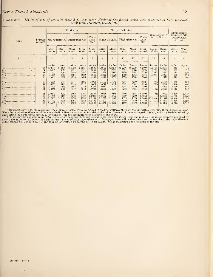
(i) Limiting dimensions.—The tables of limit¬ ing dimensions for the class 5 fit are included in section IV, herein, as tables 17A and 25A. Caution: Studs made to the tentative class 5 tolerances will not produce a satisfactory inter¬ ference fit when assembled with holes made to the alternate class 5 tolerances.
Table 6A. Class B jit for threaded .studs, allowances and tolerances for studs and tapped holes, coarse threaded studs in hard materials
Sizes Threads
per inch
Interference on pitch diameter
Pitch diameter tolerances >
Errors in half angle consuming one half of pitch di¬
ameter tolerances
Mini¬ mum
Maxi¬ mum Stud Tapped
hole 2 Stud Tapped
hole
2 3 4 5 6 7 8
Inch Inch Inch Inch Deg Min Deg Min
.. 20 0.0003 0.0018 0.0007 0.0008 0 16 0 25 Via . 18 . 0005 . 0040 .0020 .0015 0 41 0 31 %_ 16 .0005 . 0045 .0024 .0016 0 44 0 29 Jte_ 14 .0006 .0050 .0026 .0018 0 42 0 29 W_ 13 .0007 .0055 .0029 .0019 0 44 0 28
. 12 .0008 .0060 .0032 .0020 0 44 0 28 H_ 11 .0008 .0060 .0031 .0021 0 39 0 26 3/4- 10 .0009 .0065 .0033 .0023 0 38 0 26 H.. 9 .0010 .0065 .0031 .0024 0 32 0 25
1_ 8 .0011 . 0065 .0027 .0027 0 25 0 25 m_ 7 .0011 .0065 .0024 .0030 0 19 0 24 l'/4_ 7 .0012 .0065 .0023 .0030 0 18 0 24 13^_ 6 .0012 .0065 .0017 .0036 0 12 0 25 IH-.— - 6 .0013 .0070 .0021 .0036 0 14 0 25
1 Inasmuch as a moderate difference in lead between stud and tapped hole (about 0.005 inch per inch) has been shown to improve the quality of a stud fit having minimum pitch diameter interference, no lead tolerance is specified. Therefore, the tolerances specified for pitch diameter include all errors of pitch diameter and angle but not of lead. (See “3. Gages and gaging” here¬ in). Excessive lead errors, however, should be avoided, as they increase the tendency of the stud to loosen when subjected to load. Columns 7 and 8 give, tor information, the errors in angle which can be compensated for by half the tolerances on pitch diameter given in columns 5 and 6.
2 The tolerances on thq tapped hole given in column 6 are the same as those specified tor class 4 fit screws and nuts, with the exception of the H-inch size.

Screw-Thread Standards 3
i)for
elitn-
iofit
i tie
P. 41, 1(1 mi-
ttked
^Tbel
)tgo’
Table 7A. Class 5 jit for threaded studs, allowances and tolerances for studs and tapped holes, Jine-threaded studs in hard materials
Sizes Threads
per inch
Interference on pitch diameter
Pitch diameter tolerances '
Errors in half angle consuming one half of pitch di¬
ameter tolerances
Mini¬ mum
Maxi¬ mum Stud Tapped
hole 2 Stud Tapped hole
1 2 3 4 5 6 7 8
Inch Inch Inch Inch Deg Min Deg Min H.. 28 0.0005 0.00.34 0.0018 0.0011 0 58 0 35 Me. 24 .0005 .0037 .0020 .0012 0 55 0 33 H_ 24 .0006 .0044 .0026 .0012 11 0 33 Vl6_ 20 .0006 .0044 .0025 .0013 0 57 0 30 H.. 20 .0007 .0050 .0030 .0013 1 9 0 30
2(6_ 18 .0007 .0050 .0028 .0015 0 58 0 31 H_ 18 .0008 .0055 .0032 .0015 6 0 31 _ 16 .0008 .0059 .0035 .0016 4 0 29
U- 14 .0008 .0061 .0035 .0018 0 56 0 29
1..... 14 .0009 .0069 .0042 .0018 7 0 29 m_ 12 .0009 .0067 .0038 .0020 0 52 0 28 m- 12 .0011 .0060 .0029 .0020 0 40 0 28 m- 12 .0011 .0055 .0024 .0020 0 33 0 28 iH_ 12 .0012 .0050 .0018 .0020 0 25 0 28
limit-
lied in
2aA, kss 5
inter¬
ne to
1 Inasmuch as a moderate difference, in lead between stud and tapped hole (about 0.005 inch per inch) has been shown to improve the quality of a stud fit having minimum pitch diameter interference, no lead tolerance is speci¬ fied. Therefore, the tolerances specified tor pitch diameter include all errors of pitch diameter and angle but not of lead. (See “3. Gages and gaging” herein.) Excessive lead errors, however, should be avoided, as they increase the tendency of the stud to loosen when subjected to load. Columns 7 and 8 give, for information, the errors in angle which can be compensated for by half the tolerances on pitch diameter given in columns 5 and 6.
2 The tolerances on the tapped hole given in column 6 are the same as those specified for class 4 fit screws and nuts.
imid
haHaiifle linfoae littUi- olratfs
Tapped Me
D/fifis 1 25 P 31 « 29 0 29 0 28
0 28 0 2i 0 28 0 25
0 25 0 21 0 21 0 25 0 25
pedWe olastid peeiJed. mis ol if here- easetlie lands ibylialf
isttee icbsiie.
Page 29. Change paragraphs 1 and 2 to read as follows:
1. Object of Gaging.—The final results sought by gaging are to secure interchangeability, that is, the assembly of mating parts without selection or fitting of one part to another, and to insure that the product conforms to the specified dimensions within the limits of variation establishing the clos¬ est and loosest conditions of fit permissible in any given case, as provided for in the foregoing specifi¬ cations. This is accomplished usually by the use of plug and ring tliread gages. This requires the use of maximum-metal limit gages known generally as “go” gages which control the minimum looseness or maximum tightness in the fit of mating parts, and which accordingly control interchangeability, and the use of minimum-metal limit gages known generally as “not go” gages which limit the amount of looseness between mating parts, and thus con¬ trol in large measure the proper functioning of the parts.
2. Purpose of Limit Gages.—The maximum- metal limit or “go” gages control the extent of the tolerance in the direction of the limit of maximum metal, and represent the maximum limit of exter¬ nal threads and the minimum limit of internal threads. To pass inspection, parts must be accept¬ able to proper ‘ go” gages, and such mating parts will always assemble. Successful interchangeable
manufacturing has been carried on for many years with the use of “go” gages only.
“Not go” gages control the extent of the toler¬ ance in the direction of the limit of minimum metal, and represent the minimum limit of external tlireads and the maximum limit of internal threads. All parts shall be accepted if an approved “not go” gage does not enter or is not entered, or if, on or before the third turn of assembly, a definite drag is obtained which is the result of metal to metal con¬ tact simultaneously on both flanks of the thread at a number of counter positioned points. Beyond this point the gage shall not be forced by applying a torque sensibly greater than that already applied to obtain the drag fit.
This definition applies only to the use of “not go” plug and ring thread gages. This requirement is to preclude any possibility of accepting internal tlneads that are oversize for more that three tlireads or accepting external threads that are un¬ dersize, at the entering end, for more than three threads. The requirements of extreme applications such as exceptionally thin or ductile material, small number of thi-eads, etc., may necessitate modification of this practice.
An approved “not go” thread gage is one of nom¬ inal size at the minimum metal product limit with tolerance inside this limit, as shown in tables 9 and 10. In case the product is so close to the mini¬ mum metal limit that its acceptability is doubtful, a “not go” inspection gage which is at, rather than within, this limit may be used. See paragraph 3, page 42. Furthermore, the purchaser can elect to use an inspection “not go” gage with tolerance out¬ side the minimum metal product limit. See par. 6, page 31.
There is a broad, general principle in regard to limit gages which should be kept in mind; a maxi¬ mum-metal limit or “go” gage should check simul¬ taneously as many elements as possible, a mini¬ mum-metal limit gage, to be effective, can check but one element. By “effective inspection” is meant assurance that specified requirements in re¬ gard to size are not exceeded. A minimum-metal limit or “not go” thread gage made to check the pitch diameter is usually sufficient for practical purposes. The minimum-metal limit gage is made to approximate a gage for checking pitch diameter only, by reducing both the length of the thread flank and the length of thread. It is necessary that the crest of the thread be removed so that the major diameter of the plug gage shall be less than that specified for the “go” plug gage and the minor diameter of the ring gage shall be gi-eatei than that specified for the “go” ring gage. A correspond¬ ingly greater width of relief should be provicled at the root of the thread of the “not go” gage than of the “go” gage.
The truncation of the major diameter of the thread of the “not go” thread-plug gage shall be
4 Handbooks of the National Bureau of Standards
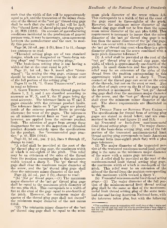
such that the width of flat will be approximately equal to p/4, and the truncation of the minor diam¬ eter of the thread ot the “not go’’ tlu’ead-ring gage shall be such that the width of flat will be 3p/8. (See “thread form of thread plug and ring gages,” p. 32, H28 (1944). On account of manufacturing conditions incidental to the production of general purpose nuts, it may be necessaiy, upon agreement between the manufacturer and the user, to mod¬ ify this practice.
Page 30, 2d col., par. 5 (b), lines 5 to 11, change two sentences to read:
“Threaded setting plugs are of two standard designs, which are designated as “basic-form set¬ ting plugs” and “truncated setting plugs.”
“The basic-form setting plug is one having a width of flat at the crest equal to p/8.”
Page 31, 1st col., line 9, msert after “deter¬ mined”; “In setting the ring gage, extreme care should be taken to prevent damage to the crest of the full portion of the setting plug.”
Pages 31 to 34, “1. Gage Tolerances”, revise to read as follows;
1. Gage Tolerances.^—Screw-thread gages for classes 1, 2, 3, and 5 are classified according to accuracy as W, X, and Y, the W gages being the most acciirate. The tolerance limits on W and X gages Coincide with the extreme product limits. The tolerance limits on Y “go” gages are placed inside of the extreme product limits to provide allowance for wear of the gages. The tolerances on all minimmn-metal limit or “not go” gages, however, are applied from the extreme product limit. The selection of gages from among these designations for use in the inspection of threaded product depends entirely upon the specifications for the product. See “recommended gage prac¬ tice,” p. 41, H28 (1944).
Page 32, 2d col., par. 2 (a), lines 9 through 17, change to read:
“A relief shall be provided at the root of the ‘go’ thread plug or ring gage, the maximum width of which is one-eighth of the pitch. This relief may be an extension of the sides of the thread from the position corresponding to this maximum width toward a sharp V. The ‘go’ thread ring gage shall clear the maximxim major diameter of the screw, and the ‘go’ thread plug gage shall clear the minimum minor diameter of the nut.”
Page 32, 2d col., par. 2 (b), change to read: “(b) ‘Not go' thread gages.—(1) The maximum
major diameter of the ‘not go’ thread plug gage shall be equal to the maximum pitch diameter of the nut plus 2/(,/3. This corresponds to a width of flat at the crest of the gage equal to one-fourth of the pitch. However, the maximum major di¬ ameter of the tlu’ead plug gage shall not exceed® the minimum major diameter of the nut minus 0.05/1.
“(2) The minimum minor diameter of the ‘not go’ thread ring gage shall be equal to the mini¬
mum pitch diameter of the screw minus /i,/3- This corresponds to a width of flat at the crest of' the gage equal to three-eighths of the pitch. However, the minimum minor diameter of the thread ring gage shall not be less than the mini-' mum minor diameter of the nut plus 0.05A. This' requirement is necessary to insure that the minor? diameter of the ‘not go’ thread ring gage is not' less than the minor diameter of the ‘go’ ring gage, which can occur with a three-eighths pitch flat on the ‘not go’ thread ring crest when there is a pitch diameter allowance on the screw combined with a large pitch diameter tolerance.® i
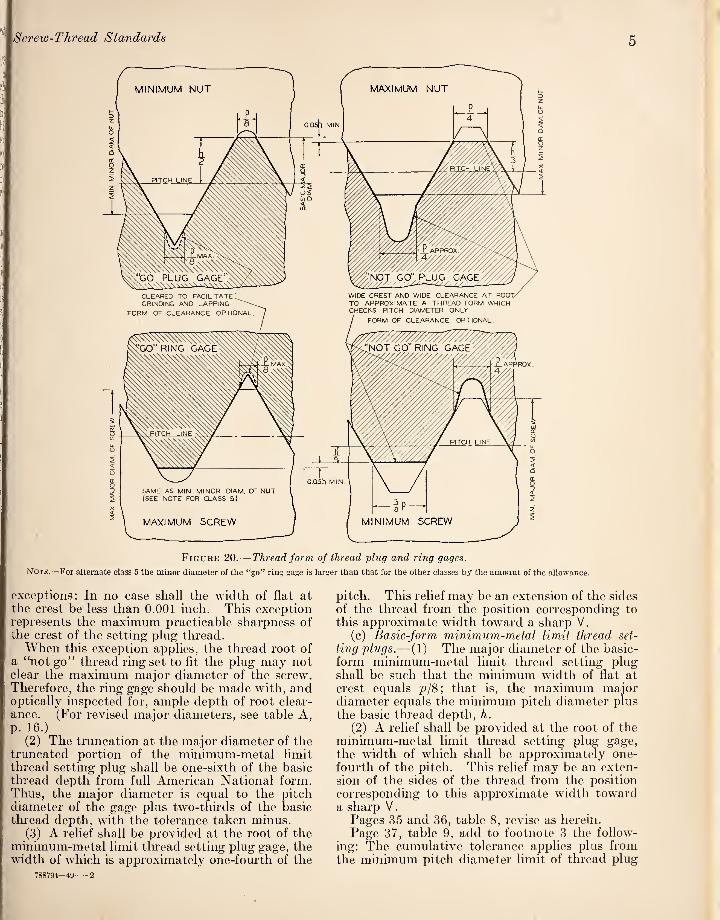
(3) A relief shall be provided at the root of thej “not go” thread plug or thread ring gage, the] width of which is approximately one-fourth of the, pitch. In small diameters and fine pitches, thisj rehef may be an extension of the sides of thej thread from the position corresponding to this! approximate width toward a sharp V. Thus,! contact of the thread gage can occur on the sides | of the tlu-eads, but not on the crest or root. Also] the effect of angle error on the fit of the gage with' the product is minimized. The “not go” thread ring gage shall clear the maximum major diameter of the screw, and the “not go” tlu’ead plug gage shall clear the minimum minor diameter of the nut. The above requirements are illustrated in figure 20.
3. Thread Form of Setting Plug Gages.—
The specifications for thread form of setting plug gages are stated in detail below, and are sum¬ marized in table 8 and figures 21 and 2lA.
(a) Truncated or basic-form maximum-metal limit thread setting plugs.—(1) The major diame¬ ter of the basic-form setting plug, and of the full portion of the truncated maximum-metal limit tlu’ead setting plug corresponds to basic American National form (one-eighth pitch flat) with a plus gage tolerance.
(2) The major diameter of the truncated por¬ tion of the truncated maximum-metal limit setting plug is the same as the minimum major diameter of the screw with a minus gage tolerance.
(3) A relief shall be provided at the root of the maximum-metal limit thread setting plug gage, the maximum width of which is one-fourth of the pitch. This relief may be an extension of the sides of the thread from the position corresponding to this maximum width toward a sharp V.
(b) Truncated minimum-metal limit thread setting plugs.-—(1) The major diameter of the full por¬ tion of the minimum-metal limit thread setting plug shall be the same as that of the maximum- metal limit thread settiDg plug of the same nom¬ inal size and having American National form, with the tolerance taken plus, but with the following
* This condition occurs in connection with small sizes of class 1 coarse and fine series threads and may occur for extreme combinations of large diameter and fine pitch of class 1 threads of special diameters, pitches, and lengths of engagement.
Screw-Thread Standards 5
CLEARED TO FACILITATE GRINDING AND LAPPING
FORM OF CLEARANCE OPTIC
WIDE CREST AND WIDE CLEARANCE AT ROOT/ TO APPROXIMATE A THREAD FORM WHICH CHECKS PITCH DIAMETER ONLY
FORM OF CLEARANCE OPTIONAL.
Figure 20.— Thread form of thread ph^g and ring gages.
Note.—For alternate class 5 the minor diameter of the “go” ring gage is larger than that for the other classes by the amount of the allowance.
exceptions: In no case shall the width of flat at the crest be less than 0.001 inch. This exception represents the maximum practicable sharpness of the crest of the setting plug thread.
WTien this exception applies, the thread root of a “not go” thread ring set to fit the plug may not clear the maximum major diameter of the screw. Therefore, the ring gage should be made with, and optically inspected for, ample depth of root clear¬ ance. (For revised major diameters, see table A, p. 16.)
(2) The truncation at the major diameter of the truncated portion of the minimum-metal limit thread setting plug shall be one-sixth of the basic thi'ead depth from full American National form. Thus, the major diameter is equal to the pitch diameter of the gage plus two-thirds of the basic thread depth, with the tolerance taken minus.
(3) A relief shall be provided at the root of the minimum-metal limit thread setting plug gage, the width of which is approximately one-fourth of the
788794-^9-2
pitch. This relief may be an extension of the sides of the thread from the position corresponding to this approximate width toward a sharp V.
(c) Basic-form minimum-metal limit thread set¬ ting plugs.—(1) The major diameter of the basic- form minimum-metal limit tlu'ead setting plug shall be such that the minimum width of flat at crest equals p/8; that is, the maximum major diameter equals the minimum pitch diameter plus the basic tlu-ead depth, h.
(2) A relief shall be provided at the root of the minimum-metal limit tlu-ead setting plug gage, the width of which shall be approximately one- fourth of the pitch. This relief may be an exten¬ sion of the sides of the thread from the position corresponding to this approximate width toward a sharp V.
Pages 35 and 36, table 8, revise as herein. Page 37, table 9, add to footnote 3 the follow¬
ing: The cumulative tolerance applies plus from the minimum pitch diameter limit of thread plug

Handbooks of the National Bureau of Standards
Table 8. Specifications for thread form, major, pitch, and minor diameters, and direction of gage tolerances of gages for American National form, and straight pipe thread form of thread *
Type of gage
Major diameter
Dimension -D.
Direc¬ tion of toler¬ ance
Width of relief 2 3
Pitch diameter
Dimension E,
Direction of tol¬ erance
Stand¬ ard
Op¬ tional
(see par. 6, P. 31)
Minor diameter
Dimension K. Direc¬ tion of toler¬ ance
Width of relief 2
Maximum-Metal Limit or “Go” Gages
Thread plug, all threads_ Thread ring:
Classes 1, 2, 3_ Class 5_
Basic form setting plug, all threads_ Truncated setting plug, all threads:
Full portion.... Truncated portion....
Plain snap gage, all threads.. Plain plug gage, all threads. .. Plain check plug gages for thread ring
gage:« “Go”..__ “Not go”___
Min Do. + Min En- p/8 max.
Max E,-{-h.
Max E,+h^ Min n,_ Max D,_
+ +
p/8 max. p/8 max.
Max E,. Max E,. Max
6 Min K„_ Max E,—2hlZ_
p/4 max.
Max E,. Max E,.
p/4 max. p/4 max.
Min K„. +
Min Ks- Max Kg.
+
Minimum-Metal Limit or “Not Go” Gages
Thread plug...
Thread ring.
Max En+2hl3, but not to exceed min Do—0.05A.
p/4 approx..
Max E„
Min E,.
+ p/4 approx.
+
Basic form setting plug, all threads_ Truncated setting plug, all threads:
Full portion... Truncated portion....
Plain snap gage, all threads...- Plain plug^gage, all threads__ Plain check plug gages for thread ring
gage: “Go”__ “Not go”..
Min Ei+h. Min E,. +
i Min E,—hl3, hut not less than min iC„+0.05ft.
p/4 approx.
* Max E.+h... Min E,+2hl3.. Min D._
+ Min E,. Min E,.
+ +
p/4 approx. p/4 approx.
Max Kn.
Min Kg. Max Kg.
1 The sjunbols used in this table are as follows: h—ha n Horith th oqri/=0.649519p for Amcrlcan National form. n-oasic aepin oi fn'eau|^Q_gggg25p for straight pipe thread form, except Dryseal. (See table 72, col. 3, p. 136, H28(1944). p = pitch. En = pitch diameter of nut.
D,=major diameter of gage. E. = pitch diameter of screw. Do=major diameter of nut. Fi'5=minor diameter of thread ring gage. D,=major diameter of screw. Fr„=minor diameter of nut. £'j=pitch diameter of gage. //=depth of sharp-V thread.
2 The thread ring gages shall clear the maximum major diameter of the screw. The thread plug gages shall clear the minimum minor diameter of the nut. 3 The width of relief on maximum-metal limit or “go” gages for straight pipe threads is p/9, and on minimum-metal limit or “not go” gages is p/4. 1 For the minor diameter of adjustable thread ring gages, “go” and “not go” plain cylindrical check plug gages made to XX tolerances are required for sizes
in. and less, and are desirable for larger sizes. See table 12. 3 The width of flat crest shall not be less than 0.001 in.; that is. Max E,+h shall not exceed Min £,+//—0.0017 in. See par. 3(b) herein. 3 For straight pipe thread ring gages, Xg=Max Eg—h for the maximum-metal limit or “go” gage, and Kg=Min E,—2hl3 for the minimum-metal limit or
“not go” gage.

Screw-Thread Standards 7
-i^r
FULL PORTION TRUNCATED PORTION
MAXIMUM-METAL LIMIT SETTING PLUG
(FOR "GO”THREAD RING GAGE)
FULL PORTION TRUNCATED PORTION
MINIMUM-METAL LIMIT SETTING PLUG (FOR "NOT GO”THREAD RING GAGE)
Figure 21.— Thread form of maxi murn-metal and mini mum-metal limit thread setting plug gages.
gages and minus from tlie maximum pitcli diameter limit of thread ring gages. The diameter equiv¬ alents of lead and angle errors are determined by applying formulas given on pages 222 and 223, H28 (1944).
Page 42, first col., par. beginning “Gaging of,” line 7, after “sizes” insert: “to reduce failure by shear when torque is applied,”.
SECTION IV. AMERICAN NATIONAL THREAD SERIES
The following are corrections and revisions of this section:
Page 47, table 16, delete class 4.
Page 49, table 17, change “class 5 fit” to “alternate class 5 fit.”
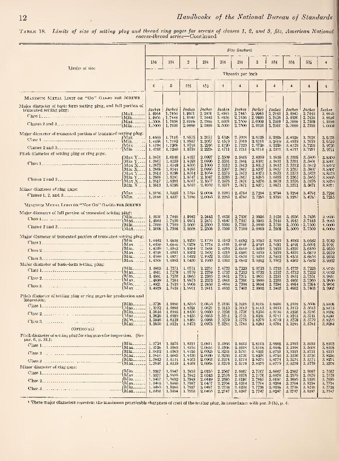
Pages 50 and 51, table 18. Revise as shown herein.
Page 54, table 19, delete class 4. Page 55, table 20, delete class 4. Page 56, table 21, column headed “Iji” change
“1.1623” to “1.1023.”' Under “not go thread
GAGES FOR SCREWS,” first line, delete “full-form setting plug and.” (The major diameters for basic-form minimum-metal limit setting plugs should correspond to a p/8 width of flat.) Change “class 5 fit” to “alternate class 5 fit.”
Page 57, table 22, change “class 5 fit” to “alter¬ nate class 5 fit.”

8
Llj 8
B/^SIC-FORM SETTING PLUG (FOR "GO”THREAD RING GAGE)
,(
Handbooks of the National Bureau of Standards |
8
MINIMUM-METAL LIMIT
BASIC-FORM SETTING PLUG (FOR“NOT GO”THREAD RING GAGE)
Figure 21 A.— Thread form of basic-form thread setting plug gages.
Page 60, table 24, delete class 4. Page 62, table 25, change “class 5 fit” to
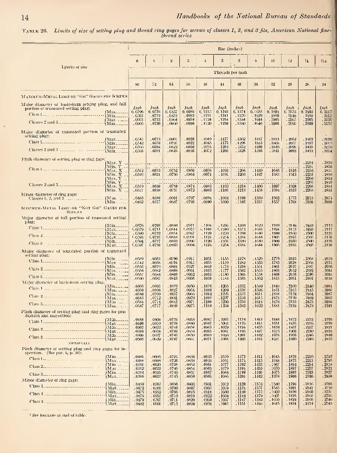
“alternate class 5 fit.” Pages 63 and 64, table 26. Revise as shown
herein. Page 65, table 27, delete class 4. Change major
diameter limits of class 1 minimum-metal limit, “not go”, ping gage for size 0-80 from “.0597” and “.0594” to “0.0596” and “.0593”.
Page 67, table 28, delete class 4. Page 68, table 29. Change “class 5 fit” to
“alternate class 5 fit”. Under “not go thread
GAGES FOR SCREWS,” first line, delete “full-form setting plug, and”. (See reference above to p. 56.)
Page 69, table 30, change “class 5 fit” to “alter¬ nate class 5 fit.”
Page 70, table 31, revise as herein. Certain drills outside of product limits have been elimi¬ nated or set in italics.'
Page 71, table 32, column headed “iKe", change “1.0216” to “1.0213”; change “.0048” to “.0051” in two places; and change “1.0312” to “1.0315”.
Page 72, table 33, change the limits for the major diameter of the fidl portion of the minimum- metal limit, “not go”, setting plugs for the first three sizes to read as follows: (See footnote 1, revised table 18):
Size- VT' Vs” Min_ .2492 .3118 .3742 Max_ .2497 .3123 .3747
In column head change “.2653” to “.3653”. Add limits for major diameter of minimum-metal
limit basic-form setting plugs as given in table A, p. 16, herein.
Page 73, table 33, column headed “iMe”, change “1.0216” to “1.0213” in two places; change “1.0219” to “1.0216”; and change “1.0213” to “1.0210.”
Page 75, table 34, column headed “iKe”, change “1.0312” to “1.0315” in two places; change “1.0309” to “1.0312”; and change “1.0315” to “1.0318”.
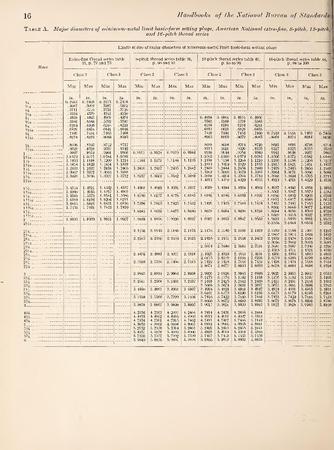
Page 80, table 38, add limits for major diameters of minimum-metal limit basic-form setting plugs as given in table A. p. 16, herein.
Page 83, table 40, column 3, change “4.44985” to “4.49985.”
Page 88, table 43, add limits for major diameters of minimum-metal limit basic-form setting plugs as given in table A, p. 16, herein.
Page 92, table 44, in col. headed “3h” change “3.1951” to “3.1961.”
Page 93, table 45, column 3, change “4.74980” to “4.74981”.
Pages 95 to 97, table 47, change side headings “Major diameter” to “Classes 2 and 3, major diameter;” and “Minor diameter” to “Classes 2 and 3, minor diameter.”
Page 96, table 47, column headed “lYiN, change heading to “UXe”.
Page 98, table 48, add limits for major diameters of minimum-metal limit basic-form setting plugs as given in table A, p. 16, herein.
Page 103, table 50, column 1, change first “2/2” to “2h”.

Screw-Thread Standards 9
Table 17A.—Limits of size of tentative class 5 fit, American National coarse-thread series, steel studs set in hard materials (cast iron, semisteel, bronze, etc.)
Sizes Threads per inch
Stud sizes Tapped-hole sizes
Recommended tap drill size
Approximate torque at full engagement
of 1}4D Major diameter Pitch diameter Minor diam¬ eter
Minor diameter Pitch diameter Major diam¬ eter
Maxi¬ mum
Mini¬ mum
Maxi¬ mum
Mini¬ mum
Maxi¬ mum >
Mini¬ mum
Maxi¬ mum
Mini¬ mum
Maxi¬ mum
Mini¬ mum 2
Nom¬ inal size
Diam¬ eter
Maxi¬ mum
Mini¬ mum
1 2 3 4 5 6 7 8 9 10 11 12 13 14 15 16
Inches Inches Inches Inches Inches Inches Inches Inches Inches Inches Inches Inches In.-lb. In.-lb. M s_ 20 0. 2500 0.2428 0.2193 0. 2186 0.1904 0.2049 0.2103 0.2175 0.2183 0.2500 0. 2090 0. 2090 105 35 Me—. 18 . 3125 . 304.3 .2804 .2784 .2483 .2622 . 2682 .2764 .2779 . 3125 . 2656 . 2656 265 80 H_ 16 . 3750 .3660 .3389 .3365 .3028 .3186 .3254 .3344 .3360 . 3750 .3230 .3230 420 120 Me. ... 14 .4375 .4277 .3961 .3935 .3549 . 37.36 .3813 .3911 .3929 . 4375 . 3750 . 3750 610 180 - 1.3 .5000 .4896 .4555 . 4.526 .4111 .4313 .4396 .4500 .4519 .5000 .4375 .4375 850 265
Me- 12 .5625 .5513 .5144 .5112 .4663 .4882 .4972 .5084 .5104 .5625 12.5mm .4921 1,170 360 H_ n .6250 .6132 .5720 .5689 .5195 .5444 .5542 .5660 . .5681 .6250 35^4 .5469 1,450 450 H-.—-- 10 .7500 .7372 . 6915 .6882 .6338 .6614 .6722 .6850 .6873 . 7500 «/64 .6719 2,300 730 - 9 .8750 .8610 .8093 .8062 .7452 .7768 .7888 .8028 .8052 .8750 25^2 .7812 3,200 1,080
1_ 8 1. 0000 . 9848 .9253 .9226 .8531 .8901 .9036 .9188 .9215 1. 0000 5144 .8906 4, 250 1,500 m_ 7 1. 1250 1. 1080 1.0387 1.0.363 .9562 .9998 1.0152 1.0322 1.0352 1.1250 1 1.0000 5, 300 1,875 IH_ 7 1.2500 1.23.30 1.1637 1 1614 1.0812 1.1248 1.1402 1.1572 1.1602 1.2500 iH 1.1250 6, 950 2,535 _ 6 1..37.50 1.3548 1.2732 1.2715 1.1770 1.2286 1.2466 1.2667 1.2703 1.3750 mu 1.2344 8,150 2,970
IH- 6 1. 5000 1.4798 1.3987 1.3966 1.3025 1.3536 1.3716 1.3917 1.3953 1.5000 mAi 1.3594 10,400 3,900
' Dimensions given for the maximum minor diameter of the screw are figured to the intersection of the worn tool arc with a center line through crest and root. The minimum minor diameter of the screw shall be that corresponding to a flat at the minor diameter of the screw equal to HXp, and may be determined by subtracting the basic thread depth, k, (or 0,649.'ip) from the minimum pitch diameter of the screw.
2 Dimensions for the minimum major diameter of the tapped hole correspond to the basic flat i'AXp), and the profile at the major diameter produced by a worn tool must not fall below the basic outline. The maximum major diameter of the tapped hole shall be that corresponding to a flat at the major diameter of the tapped hole equal to HtXp, and may be determined by adding l%Xh. (or 0.7939p) to the maximum pitch diameter of the nut.
3 Selective assembly in the case of the H-ineh size may be required on account of the small tolerances necessary on pitch diameter. To avoid breaking a mild steel stud, the maximum interference on pitch diameter of 0.0018 inch must not he exceeded. The use of H"-28, instead of J4"-20, is recommended.

Handbooks of the National Bureau of Standards
Table 18. Limits of size of setting plug and thread ring gages for screws of classes 1, 2, and S fits, American National coarse-thread series
Size (inches)
Limits of size
1 2 3 4 5 6 8 10 12 Me
Threads per inch
64 56 48 40 40 32 32 24 24 20 18
Maximum-Metai L7.m!t or “Go" Gages for Screws
Major diameter of basic-form setting plug, and full portion of truncated setting plug: Inch Inch Inch Inch Inch Inch Inch Inch Inch Inch Inch
, /Max_ 0. 0727 0. 0856 0.0985 0.1114 0.1244 0.1374 0.1634 0.1892 0. 2152 0. 2490 0. 3114 Class 1----Imjp .0723 . 0852 .0981 . 1110 .1240 . 1.369 .1629 . 1887 .2147 .2485 .3109
„ /Max_ . 0734 . 0864 .0994 . 1124 .1254 . 1385 . 1645 .1905 . 2165 .2505 . 31.30 Classes 2 and 3.__--\Min . 07.30 .0860 .0990 .1120 .1250 , 1380 .1640 ,1900 .2160 .2500 .3125
Major diameter of truncated portion of truncated setting plug: .0671 . 0796 .0919 . 1042 . 1172 . 1293 . 15.53 . 1795 . 2055 . 2383 .2995
Class 1--^Min_ . 0667 .0792 . 0915 . 1038 . 1168 .1288 . 1.548 . 1790 .2050 . 2378 .2990 „ j „ /Max_ .0692 .0820 .0946 . 1072 . 1202 . 1326 . 1.586 . 18.34 .2094 .2428 . .3043
Classes 2 and 3_ iMin .0688 .0816 .0942 . 1068 . 1198 . 1.321 . 1581 . 1829 .2089 .2423 .3038
Pitch diameter of setting plug or ring gage: fMax. Y . 2158 .2746 Min. Y .2155 . 2743
Class L-.--- Max.x/_: _; .0622 . 0736 .0846 .0948 . 1078 . 1166 . 1426 . 1616 .1876 .2160 .2748 iMin. X ___ .0620 .0734 .0844 .0946 . 1076 . 1163 . 1423 . 1613 . 1873 .2157 .2745
. 2173 . 2762
.2170 .2759 Classes 2 and 3..v .0629 .0744 .0855 .0958 . 1088 . 1177 . 1437 . 1629 . 1889 .2175 .2764
IMin. X_ .0627 .0742 .0853 .0956 . 1086 . 1J74 .1434 . 1626 . 1886 . 2172 .2761
Minor diameter of ring gage: j „ /Max_ .0561 . 0667 . 0764 .0849 .0979 . 1042 .1302 . 1449 . 1709 . 1959 .2524
Classes 1, 2, and 3-IMin .0557 . 0663 .0760 .0845 .0975 . 10.37 . 1297 , 1444 . 1704 . 1954 ,2519
Minimum-Metal Limit or "Not Go" Gages for Screws
Major diameter of full portion of truncated setting plug: .0710 .0841 .0974 . 1109 .1239 .1369 . 1629 .1887 .2147 .2485 .3109
Class 1-iMax_ 1 .0714 I .0845 1.0978 1 .1113 I . 1243 . 1.374 . 1634 . 1892 .2152 .2490 .3114 .0724 .0857 .0990 . 1120 . 12.50 . 1380 . 1640 . 1900 .2160 .2500 .3125
1 .0728 1 .0861 .0994 . 1124 . 1254 . 1385 . 1645 . 1905 . 2165 .2505 . 3130 „ /Min_ .0729 .0860 . 0990 .1120 . 1250 . 1380 . 1640 .1900 .2160 .2500 .3125
class d-\Max__ . 1 .0733 .0864 .0994 . 1124 . 1254 . 1.385 . 1645 . 1905 .2165 .2505 .3130
Major diameter of truncated portion of truncated setting plug: .0660 .0781 .0901 . 1018 . 1148 . 1258 . 1518 . 1745 .2005 .2.321 .2927
Class 1 -(Max_ .0664 .0785 .0905 . 1022 . 1152 . 1263 . 1523 . 1750 .2010 .2326 .2932 .0674 .0797 .0919 . 1038 . 1168 . 1280 . 1540 . 1771 . 2031 .2351 .2959 .0678 .0801 . 0923 . 1042 . 1172 . 1285 . 1545 . 1776 . 2036 .2.356 .2964
„ /Min_ .0679 .0802 .0925 . 1045 . 1175 . 1288 . 1548 . 1780 .2040 .2.361 .2970 '-'lass 3- - - --- - -- - (Max.. . .0683 .0806 .0929 . 1049 . 1179 .1293 . 1553 .1785 .2045 .2366 .2975
Major diameter of basic-form setting plug: .0693 .0820 .0946 . 1072 . 1202 . 1326 . 1586 . 1836 .2096 .2429 .3047
L iass 1- - . ... - . . - -\Max_. . .0697 .0824 .0950 . 1076 . 1206 . 1331 . 1591 . 1841 .2101 .2434 .3052 .0707 . 0836 .0904 . 1092 . 1222 . 1348 . 1608 . 1862 .2122 .2459 .3079
L lass - - ---(Max.. .0711 .0840 .0968 . 1096 . 1226 . 1353 . 1613 . 1867 .2127 . 2464 .3084 p,. „ „ /Min_ .0712 .0841 .0970 . 1099 . 1229 . 1356 . 1616 .1871 .2131 .2469 .3090 Class 3---iMeY .0716 .0845 .0974 . 1103 . 1233 .1361 . 1021 .1876 .2136 .2474 .3095
Pitch diameter of setting plug or ring gages for production and inspection:
.0596 .0708 .0815 .0914 . 1044 . 1128 .1388 .1570 .1830 .2109 .2691 Class 1...\Max. _ .0598 .0710 .0817 .0916 .1046 . 1131 . 1391 . 1673 . 1833 .2112 .2694
.0610 .0724 . 0833 . 0934 .1064 .1150 . 1410 .1596 . 1856 .2139 .2723
.0612 .0726 .0835 .0936 . 1066 . 1153 . 1413 . 1599 . 1859 .2142 .2726 o /Min_ .0615 .0729 .0839 .0941 . 1071 . 1158 . 1418 .1605 .1865 .2149 .2734
Class 3---_ .0617 .0731 .0841 .0943 . 1073 . 1161 . 1421 . 1608 .1868 .2152 .2737
(optional)
Pitch diameter of setting plug or ring gages for inspection (see par. 6, p. 31):
1 /Min- .0594 .0706 .0813 .0912 . 1042 .1125 .1385 .1567 . 1827 .2106 .2688 Class 1--- . 0596 .0708 .0815 .0914 . 1044 . 1128 .1388 .1570 . 1830 .2109 .2691
r'loooo /Min- .0608 .0722 .0831 .0932 . 1062 . 1147 . 1407 .1593 . 1853 .2136 .2720 Class 2- .0610 .0724 .0833 .0934 . 1064 . 1150 . 1410 .1596 . 1856 .2139 .2723
Q /Min- .0613 .0727 .0837 .0939 . 1069 . 1155 . 1415 . 1602 .1862 .2146 .2731 .0615 .0729 .0839 .0941 . 1071 . 1158 . 1418 . 1605 . 1865 .2149 .2734
Minor diameter of ring gage: .0566 . 0673 .0771 .0860 .0990 . 1060 . 1320 .1480 .1740 .2001 .2571 .0570 .0677 .0775 .0864 .0994 . 1065 . 1325 . 1485 . 1745 .2006 .2576
r^iacc 9 - .0576 .0685 .0788 .0880 . 1010 . 1082 . 1342 . 1506 . 1766 .2031 .2603 Class 2.---- .0580 .0689 .0792 .0884 . 1014 . 1087 . 1347 . 1511 . 1771 .2036 .2608
.0581 .0690 .0794 .0887 . 1017 .1090 . 1350 . 1515 . 1775 .2041 .2614 Class 3----_ .0585 .0694 .0798 .0891 . 1021 . 1095 . 1355 . 1520 . 1780 .2046 .2619
1 See footnote at end of table.
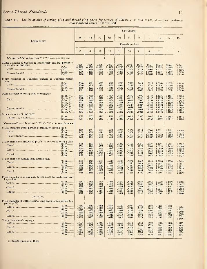
Screw-Thread Standards 11
Table 18. Limits of size of setting plug and thread ring gages for screws of classes 1, 2, and 3 fits, American National coarse-thread series—Continued
Size (inches)
Limits of size
Me Me A 1 Hi IM m
Threads per inch
16 14 13 12 11 10 9 8 7 7 6
Maximum-Metal Limit or “Go” Gages for Screws
Major diameter of basic-form setting plug, and full portion of Inch truncated setting plug:
Class 1... - --- -- - -
Inch Inch Inch Inch Inch Inch Inch Inches Inches Inches Max_ 0.3738 0. 4360 0. 4984 0. 5607 0. 6230 0. 7478 0. 8726 0. 9973 1.1218 1.2468 1.3714
)Mm_ .3732 .4354 .4978 .5601 .6224 .7472 .8719 .9966 1.1211 1. 2461 1. 3706 (Max.. ... .3756 .4381 .5006 .5631 .6256 .7506 .8757 1.0007 1.1257 1. 2507 1. 3758
l^labSca ^ dllU o----^ A/Tin
Major diameter of truncated portion of truncated setting
.3750 .4375 .5000 .5625 .6250 .7500 .8750 1. 0000 1.1250 1. 2500 1. 3750
plug:
Class 1_ - - ..- - 'Max.. . .3606 .4214 .4830 .5443 .6054 .7288 .8519 .9744 1.0963 1. 2213 1. 3416 Min_ .3600 .4208 .4824 .6437 .6048 .7282 .8512 .9737 1. 0956 1. 2206 1. 3408
Classes 2 and 3_ ___ (Max_ .3660 .4277 .4896 .5513 .6132 .7372 .8610 .9848 1. 1080 1. 2330 1. 3548 (Min_ .3654 . 4271 .4890 .5507 .6126 .7366 .8603 .9841 1.1073 1. 2323 1. 3540
Pitch diameter of setting plug or ring gage: Max. Y.... .3324 .3888 .4476 . 5058 .5632 .6820 .7995 .9152 1. 0281 1.1531 1. 2620
Class 1__-.. Min. Y ... .3320 .3884 . 4472 .5054 .5628 .6816 .7990 .9147 1. 0276 1.1526 1. 2615 Max. X.... .3326 .3890 .4478 .5060 .5634 .6822 .7997 .9154 1.0283 1. 1533 1. 2623 Min. X_ .3323 .3887 .4475 .5057 .5631 .6819 .7994 .9150 1. 0279 1. 1529 1. 2619 Max. Y_ .3342 .3909 .4498 .5082 .5658 .6848 .8026 .9186 1.0320 1. 1570 1.2664
Classes 2 and 3_ _ _ _ ...< Min. Y.... .3338 .3905 .4494 .5078 .5654 .6844 .8021 .9181 1. 0315 1. 1565 1. 2659 Max. X,... .3.344 .3911 .4500 .5084 .5660 .6850 .8028 .9188 1. 0322 1. 1572 1. 2667 Min. X.... .3341 .3908 .4497 . .5081 .5657 .6847 .8025 .9184 1. 0318 1.1568 1.2663
Minor diameter of ring gage:
Classes 1, 2, 3, and 4- .. ...
Miminum-Metal Limit or “Not Go*’ Gages fo
Major diameter of full portion of tnmcated setting
'Max. .. .3073 .3602 . 4167 .4723 .5266 .6417 . 7547 .8647 .9704 1. 09.54 1. 1946 Min .. .
R Screws
plug:
.3067 . 3596 .4161 .4717 . 5260 . 6411 .7540 .8640 .9697 1.0947 1.1938
Class 1__ _ -- - Min_ .3732 .4354 .4978 . 5601 .6224 .7472 .8719 .9966 1. 1211 1. 2461 1.3706 Max__ .3738 . 4360 .4984 .5607 .6230 .7478 .8726 .9973 1.1218 1. 2468 1. 3714
Classes 2 and 3. .. . .
Major diameter of truncated portion of truncated se
Min_ .3750 .4375 . 5000 .5625 .6260 .7500 .8750 1. 0000 1.1250 1. 2500 1. 3750 Max_
tting plug:
.3756 .4381 .5006 .5631 .6256 .7506 .8757 1. 0007 1.1257 1. 2507 1. 3758
Class 1_ 'Min_ .3528 .4123 .4731 .6336 .5937 .7157 .8371 .9577 1.0771 1. 2021 1. 3192 Max... .. .3534 .4129 .4737 .5342 .5943 .7163 .8378 .9584 1. 0778 1. 2028 1. 3200
Class 2_ 'Min_ .3564 .4165 . 4775 .5383 .5989 .7213 . 8432 . 9646 1. 0849 1. 2099 1. 3280 Max_:. .3570 . 4171 . 4781 . 5.389 . 5995 .7219 .8439 .9653 1. 0856 1. 2106 1. 3288
Class 3__ Min . .3577 . 4178 . 4790 .5399 .6006 . 7232 .8453 .9668 1. 0875 1.2125 1.3310 Max_ .3583 . 4184 . 4796 . 5405 . 6012 .7238 .8460 .9675 1. 0882 1. 2132 1. 3318
Major diameter of basic-form setting plug:
Class 1__ -. -. . 'Min_ .3663 .4278 .4898 . 5516 .6133 .7374 .8612 .9848 1. 1080 1. 2330 1. 3553 Max_ .3669 . 4284 . 4904 .5522 .6139 .7380 .8619 .9855 1. 1087 1. 2337 1. 3561
Class 2... ... ... ... Min_ .3699 .4320 . 4942 .6563 . 6185 . 7430 .8673 .9917 1. 1158 1. 2408 1. 3641 Max_ .3705 .4326 .4948 .5569 . 6191 .7436 .8680 .9924 1. 1165 1.2415 1. 3649
Class 3_
Pitch diameter of setting plug or ring gages for prod
Min_ .3712 .4333 .4957 . 5579 .6202 . 7449 .8694 .9939 1.1184 1. 2434 1. 3671 Max_
uction and
.3718 .4339 . 4963 .5585 . 6208 .7455 .8701 .9946 1. 1191 1. 2441 1. 3679
inspection:
Class 1___ _ Min_ .3263 .3820 .4404 .4981 .5549 .6730 .7897 .9043 1. 0159 1. 1409 1. 2478 Max. .. . .3266 .3823 .4407 .4984 . 6552 .6733 .7900 .9047 1.0163 1. 1413 1. 2482
Class 2_ Min... ... .3299 .3862 .4448 .6028 .6601 .6786 .7958 .9112 1. 0237 1. 1487 1. 2566 Max.. _ . .3302 .3865 .4451 . 5031 .5604 .6789 .7961 .9116 1. 0241 1.1491 1. 2570
Class 3 _ - - .... Min_ .3312 .3875 . 4463 .5044 .5618 .6805 .7979 . 91.34 1. 0263 1.1513 1. 2596 Max_ .3315 .3878 .4466 . 5047 .5621 .6808 .7982 .9138 1. 0267 1.1517 1. 2600
(OPTIONAL)
Pitch diameter of setting plug or ring gages tor inspection (see par. 6, p. 31):
Min_ Class 1_ ___
.3260 .3817 . 4401 . 4978 . 5546 .6727 .7894 .9039 1. 0155 1. 1405 1. 2474 Max_ .3263 .3820 .4404 .4981 .5549 .6730 .7897 . 9043 1. 0159 1.1409
Class 2_ _ Min_ .3296 .3859 .4445 . 5025 .6598 .6783 .7955 .9108 1. 0233 1.1483
1.2562 Max_ .3299 .3862 .4448 .5028 .5601 .6786 .7958 .9112 1. 0237 1. 1487 Min_ .3309 .3872 .4460 . 5041 .5615 .6802 .7976 . 9130 1. 0259 1. 1509
1. 2566 1. 2592 1. 2596
Minor diameter of ring gage:
Max_ . 3312 .3875 . 4463 . 5044 .5618 .6805 .7979 .9134 1. 0263 1.1513
Class 1__ _ Min. .3128 .3665 .4238 .4801 .5352 .6514 .7656 .8772 .9850 1.1100 1.2117
Class 2....... Max_ .3134 .3671 .4244 .4807 .5358 .6520 .7663 .8779 .9857 1.1107 1. 2125 Min_ .3164 .3707 .4282 .4848 .5404 .6570 .7717 .8841 .9928 1. 1178 1. 2205
Class 3_____ Max_ .3170 .3713 .4288 .4854 .5410 .6576 .7724 .8848 .9935 1.1185 1. 2213 Min .. . .3177 .3720 .4297 .4864 .5421 .6589 . 7738 .8863 .9954 1. 1204 1. 2235 Max_ .3183 .3726 .4303 .4870 .5427 . 6595 .7745 .8870 .9961 1.1211 1. 2243
' See footnote at end of table.
12 Handbooks of the National Bureau of Standards
Table 18. Limits of size of setting plvg and thread ring gages for screws of classes 1, 2, and 3, fits, American National coarse-thread series—Continued
Limits of size
IH Wi 2 2H m m 3 3H 316 3%
Size (inches)
Threads per inch
6 5 m 4H 4 4 4 4 4 4 4
Maximum Metal Limit ok “Go” Gages for Screws
Major diameter of basic form setting plug, and full portion of truncated setting plug; Inches Inches Inches Inches Inches Inches Inches Inches Inches Inches Inches
Class 1 _ --- - - -• Max 1. 4964 1. 7456 1.9951 2. 2451 2. 4945 2.7445 2. 9945 3.2445 3.4945 3.7445 3.9945 Min_-- 1. 4956 1.7448 1.9943 2. 2443 2. 4936 2.7436 2.9936 3. 2436 3.4936 3. 7436 3.9936
Classes 2 and 3--- -• Max. 1. 5008 1. 7508 2.0008 2. 2508 2. 5009 2.7509 3.0009 3. 2509 3. 5009 3. 7509 4.0009 Min_ 1. 5000 1. 7500 2.0000 2. 2500 2. 6000 2.7600 3. 0000 3.2500 3.5000 3. 7500 4.0000
Major diameter of truncated portion of truncated setting plug: , flvlax- 1. 4666 1.7110 1.9575 2. 2075 2.4528 2. 7028 2.9528 3.2028 3. 4528 3. 7028 3. 9528
Min ... . 1. 4658 1. 7102 1.9567 2. 2067 2. 4519 2.7019 2.9519 3. 2019 3.4519 3. 7019 3. 9519
Classes 2 and 3__ . . _ . . ■ Max_ 1. 4798 1. 7268 1.9746 2. 2246 2. 4720 2. 7220 2. 9720 3. 2220 3.4720 3. 7220 3. 9720 Min -- 1. 4790 1. 7260 1.9738 2.2238 2.4711 2. 7211 2.9711 3. 2211 3.4711 3. 7211 3.9711
Pitch diameter of setting plug or ring gage: Max Y..-. 1. 3870 1.6146 1.8497 2. 0997 2. 3309 2. 5809 2. 8309 3. 0809 3.3309 3. 5809 3.8309
Class 1___ _■ Min Y..__ 1.3865 1.6139 1.8490 2. 0990 2. 3301 2. 5801 2.8301 3. 0801 3.3301 3. 5801 3.8301 Max X_ 1.3873 1. 6149 1.8500 2.1000 2. 3312 2. 5812 2. 8312 3. 0812 3.3312 3. 5812 3. 8312 Min X--.. 1.3869 1.6144 1. 8495 2. 0995 2. .3307 2. 5807 2. 8307 3.0807 3. 3307 3. 5807 3. 8307 Max Y---- 1.3914 1. 6198 1. 8554 2.1054 2. 3373 2. 5873 2. 8373 3. 0873 3. 3373 3. 5873 3.8373
Classes 2 and 3__ Min Y--.- 1.3909 1. 6191 1. 8647 2.1047 2. 3365 2. 5865 2. 8365 3. 0865 3. 3365 3. 5865 3.8365 Max X_ 1.3917 1. 6201 1. 8557 2.1057 2. 3376 2. 6876 2. 8376 3. 0876 3. 3376 3. 5876 3. 8376 Min X-.-. 1. 3913 1. 6196 1. 8552 2.1052 2. 3371 2. 5871 2. 8371 3.0871 3. 3371 3. 5871 3.8371
Minor diameter of ring gage:
Classes 1, 2, and 3 . .. . . Max_ 1.3196 1. 5335 1. 7594 2. 0094 2. 2294 2.4794 2. 7294 2.9794 3. 2294 3. 4794 3. 7294 Min_ 1.3188 1. 5327 1. 7586 2. 0086 2. 2285 2. 4785 2. 7285 2. 9785 3.2285 3. 4785 3. 7285
Minimum Metal Limit or “Not Go” Gages for Screws
Major diameter of full portion of truncated setting plug: , /Min- 1.4956 1.7448 1. 9943 2. 2443 2. 4936 2, 7436 2. 9936 3. 2436 3. 4936 3. 7436 3. 9936
Max_ 1. 4964 1. 7456 1. 9951 2. 2451 2. 4945 2. 7445 2.9945 3. 2445 3. 4946 3.7445 3. 9945
Classes 2 and 3_____ _ Min_ 1. 5000 1. 7500 2. 0000 2. 2500 2. 5000 2. 7500 3. 0000 3. 2500 3.5000 3. 7500 4. 0000 Max_ 1. 5008 1. 7508 2.0008 2. 2508 2. 5009 2. 7509 3. 0009 3. 2509 3.5009 3.7509 4. 0009
ilajor diameter of truncated portion of truncated setting plug: , /Min- 1. 4442 1.6838 1.9270 2.1770 2. 4182 2.6682 2.9182 3.1682 3. 4182 3.6682 3.9182
Max_ 1. 4450 1.6846 1. 9278 2.1778 2.4191 2. 6691 2.9191 3.1691 3.4191 3. 6691 3.9191
Class 2_ _ _ Min_ 1. 4530 1. 6943 1. 9384 2.1884 2. 4310 2. 6810 2.9310 3.1810 3. 4310 3. 6810 3.9310 Max_ 1. 4538 1. 6951 1.9392 2.1892 2. 4319 2. 6819 2.9319 3.1819 3. 4319 3.6819 3. 9319
Class 3_ _ Min_ 1.4560 1. 6977 1. 9422 2.1922 2. 4353 2. 6853 2. 9353 3.1853 3.4353 3.6853 3.9353 Max_ 1. 4568 1. 6985 1. 9430 2.1930 2. 4362 2. 6862 2. 9362 3.1862 3. 4362 3. 6862 3.9362
Major diameter of basic-form setting plug:
Class 1_j___ Min_ 1. 4803 1. 7271 1. 9761 2. 2251 2. 4723 2. 7223 2. 9723 3. 2223 3. 4723 3. 7223 3.9723 Max_ -- 1.4811 1. 7279 1. 9769 2. 2259 2. 4732 2. 7232 2. 9732 3. 2232 3. 4732 3. 7232 3.9732
Class 2___ Min_ 1. 4891 1. 7376 1.9865 2. 2365 2. 4851 2. 7351 2. 9851 3. 2351 3. 4851 3. 7351 3.9851 Max_ 1. 4899 1. 7.384 1. 9873 2. 2373 2. 4860 2. 7360 2. 9860 3. 2360 3. 4860 3. 7360 3.9860
Class 3_ _ _ Min_ 1.4921 1. 7410 1. 9903 2. 2403 2. 4894 2. 7394 2. 9894 3. 2394 3. 4894 3. 7394 3.9894 Max_ 1. 4929 1.7418 1.9911 2.2411 2. 4903 2. 7403 2. 9903 3. 2403 3.4903 3. 7403 3.9903
Pitch diameter of setting plug or ring gages for production and inspection:
Class 1_ Min_ 1.3728 1.5980 1. 8316 2. 0816 2. 3108 2. 6608 2. 8108 3. 0608 3.3108 3. 5608 3. 8108 Max_ 1. 3732 1. 5985 1.8321 2. 0821 2.3113 2. 5613 2. 8113 3. 0613 3. 3113 3. 5613 3. 8113
Class 2_ _ -- ___ Min_ 1.3816 1. 6085 1. 8430 2. 0930 2. 3236 2. 5736 2. 8236 3. 0736 3. 3236 3. 67.36 3. 8236 Max_ 1. 3820 1. 6090 1. 8435 2. 0935 2. 3241 2. 5741 2. 8241 3. 0741 3. 3241 3. 5741 3. 8241
Class 3_ --- - - -- _ Min_ 1.3846 1.6119 1. 8468 2. 0968 2. 3279 2. 6779 2. 8279 3. 0779 3. 3279 3. 5779 3. 8279 Max_ 1. 3850 1.6124 1. 8473 2. 0973 2. 3284 2. 5784 2. 8284 3. 0784 3. 3284 3. 5784 3. 8284
(Optional)
Pftch diameter of setting plug tor ring gages for inspection. (See par. 6, p. 31.)^
Class 1_ _ Min_ 1. 3724 1. 5975 1.8311 2. 0811 2. 3103 2. 5603 2. 8103 3. 0603 3. 3103 3. 5603 3. 8103 Max_ 1. 3728 1. 5980 1.8.316 2. 0816 2. 3108 2. 5608 2. 8108 3. 0608 3. 3108 3. 5608 3. 8108
Class 2. ... . Min_ 1.3812 1. 6080 1. 8425 2. 0925 2. 3231 2. 5731 2. 8231 3. 0731 3. 3231 3. 5731 3. 8231 Max... - 1.3816 1. 6085 1.8430 2. 0930 2. 3236 2. 5736 2. 8236 3.0736 3. 3236 3. 5736 3. 8236
Class 3_ _ ___ Min. 1. 3842 1.6114 1. 846.3 2. 0963 2. 3274 2. 5774 2. 8274 3. 0774 3. 3274 3. 5774 3. 8274 Max_ 1. 3846 1.6119 1.8468 2. 0968 2. 3279 2. 5779 2. 8279 3.0779 3. 3279 3. 5779 3. 3279
Utinor diameter of ring gage:
Class 1_ .. .. . _ _ Min_ 1.3367 1. 5547 1. 7835 2. 0.335 2. 2567 2. 5067 2. 7667 3.0067 3. 2567 3.5067 3. 7567 Max_ 1. 3375 1. 5555 1. 7843 2. 0343 2. 2676 2. 6076 2. 7576 3.0076 3. 2576 3. 5076 3. 7576
Class 2_____ __ _ Min_ 1. 3455 1. 5652 1. 7949 2. 0449 2. 2696 2. 5195 2. 7695 3. 0195 3. 2695 3. 6195 3.7695 Max_ 1. .3463 1. 5660 1. 7967 2. 0457 2. 2704 2. 6204 2. 7704 3. 0204 3. 2704 3. 6204 3. 7704
Class 3___ _ Min_ 1.3485 1. 5686 1. 7987 3. 0487 2. 2738 2. 5238 2, 77.38 3. 0238 3. 2738 3.5238 3. 7738 Max. _ _ 1.3493 1. 5694 1. 7995 2. 0495 2. 2747 2. 5247 2. 7747 3. 0247 3. 2747 3. 5247 3. 7747
■ These major diameters represent the maximum practicable sharpness of crest of the setting plug, in accordance with par. 3 (b), p. 4.
Screw-Thread Standards 13
Table 25A. Limits of size of tentative class 5 fit, American National fine-thread series, steel studs set in hard materials (cast iron, semisteel, bronze, etc.)
Sizes Threads per inch
stud sizes Tapped-hole sizes
Recommended tap drill size
Approximate torque at full engagement
of lHi> Major diameter Pitch diameter Minor diam¬ eter
Minor diameter Pitch diameter Major diam¬ eter
Maxi¬ mum
Mini¬ mum
Maxi¬ mum
Mini¬ mum
Maxi¬ mum '
Mini¬ mum
Maxi¬ mum
Mini¬ mum
Maxi¬ mum
Mini¬ mum 2
Nom¬ inal size
Diam¬ eter
Maxi¬ mum
Mini¬ mum
1 2 3 4 5 6 7 8 9 10 11 12 13 14 15 16
Inches Inches Inches Inches Inches Inches Inches Inches Inches Inches Inches Inches in.lb.. in.-lb. 28 0. 2500 0. 2438 0.2302 0. 2284 0. 2096 0. 2167 0. 2206 0. 2268 0. 2279 0. 2500 0.2187 0. 2187 140 45
Me_ 24 .3125 . 3059 .2891 .2871 . 2650 . 2743 .2788 .2854 . 2866 .3125 .2770 .2770 230 70 H_ 24 .3750 .3684 .3528 .3497 .3282 . 3368 . 341.3 .3479 . .3491 . 3750 . 3390 .3390 410 125 Me_ 20 . 4375 . 4303 ,4094 .4069 .3805 . 3924 . 3978 . 4050 .4063 .4375 . 3970 .3970 540 170 y-> _ 20 .5000 .4928 .4725 .4695 .4436 . 4549 .4603 .4675 .4688 . 5000 .4576 810 260
Me._ 18 .5625 .5543 .5314 .5286 . 499.3 .5122 .5182 5264 .5279 .5625 3^4 . 51.56 1,040 330 9s . 18 .6250 .6168 .5944 .5912 , 5623 . 5747 .5807 .5889 .5904 . 6250 3^4 .5781 1,430 460 34 ... 16 . 7500 . 7410 . 7153 .7118 .6792 . 6936 .7004 .7094 . 7110 . 7500 .6970 2,200 685 ___ 14 .8750 .8652 . 8.347 . 8312 . 79.35 .8111 .8188 .8286 . 8304 .8750 .8125 3, 070 945
1___ 14 1.0000 .9902 . 9605 .9563 .9193 .9361 .9438 . 9.536 .9554 1.0000 ‘Me . 9375 4, 590 1, 410 IH_ 12 1.1250 1.1138 1. 0776 1, 0738 1. 0295 1.0.507 1.0597 1.0709 1.0729 1.1250 1.0552 5, 620 1,750 134--- 12 1.2500 1. 2388 1.2019 1.1990 1.1.5.38 1.1757 1. 1847 1.1959 1.1979 1.2500 30.0mm 1.1811 6, 960 2,530 1?^_ 12 1.37,50 1.36.38 1.1364 1.3240 1.2782 1.3007 1. 3097 1.3209 1..3229 1..37.50 1. 3052 8, 440 3,225 ly,- 12 1.5000 1. 4888 1.4509 1.4491 1.4028 1. 4257 1.4347 I. 4459 1. 4479 1. 5000 1.4302 10, 070 4, 215
1 Dimensions given for the maximum minor diameter of the screw are figui'ed to the intersection of the worn tool arc with a center line through crest and root. The minimum minor diameter of the screw shall be that corresponding to a flat at the minor diameter of the screw equal to iiXp, and may be determined by subtracting the basic thread depth, ft, (or 0.n495p) from the minimum pitch diameter of the screw.
2 Dimensions for the minimum major diameter of the tapped hole correspond to the basic flat (HXyt), and the profile at the major diameter produced by a worn tool must not fall below the basic outline. The maximum major diameter of the tapped hole shall be that corresponding to a flat at the major diameter of the tapped hole equal to HrXp, and may be determined by adding 156Xft (or 0.7939p) to the maximum pitch diameter of the nut.
788794°—^9-3
14 Handbooks of the National Bureau of Standards
Table 26. Limits of size of setting plug and thread ring gages for screws of classes 1, 2, and 3 fits, American National fine- thread series
Size (inches)
Limits of size
Maximi’m-Metai. Limit OR “Go" Gaoes for Screw.s
Major diameter of basic-form setting plug, and full portion of truncated setting plug;
, /Max_ Class 1-iMin_
Classes 2 and 3-{^fn
Major diameter of truncated portion of truncated setting plug:
, /Max_ Class 1-\Min..
Classes 2 and 3-{lllfn
Pitch diameter of setting plug or ring gage: (Max. Y._..
, I Min. Y_ Class 1-----IMax. X-...
I Min. X._.. Max. Y....
Classes 2 and 3---)Max X
iMin.’ X \ Minor diameter of ring gage:
Cla.sses 1, 2, and 3_ /Max_ \Min_
Minimum-Metal Li.mit or “Not Go" Gages for Screws
Major diameter of full portion of truncated setting plug:
, /Min- Class 1--
/Min. Class 2-iMaxv;::;;
Class 3-{M™/-;;::; Major diameter of truncated portion of truncated
setting plug: /Min_
-\Max_ /Min -.
Class 3-
Alajor diameter of basic-form .setting plug;
Class 1.
Class 2.
Class!-
Class 2-{Mr--
Class 3- /Min.. IMax.
Pitch diameter of setting plug and ring gages for pro¬ duction and inspection:
Class 1--
Class 2-{S......
Class 3-
(OPTIONAL)
Pitch diameter of setting plug and ring gages for in¬ spection. (See par. 6, p. 31):
Class 1-
Class 2-{m^v::::
.—--{mSv;:::: Minor diameter of ring gage:
Class 1-{Mm-.
Class 2-{uSf-—
Class 3-(Mm--
0 1 2 3 4 5 6 8 10 12 Me
Threads per inch
80 72 64 56 48 44 40 36 32 28 28 24
Inch Inch Inch Inch Inch Inch Inch Inch Inch Inch Inch Inch 0. 0596 0. 0726 0.0857 0.0986 0.1115 0.1245 0.1374 0.1633 0.1894 0. 2153 0. 2493 0, 3117 .0593 .0723 .0853 .0982 . nil . 1241 . 1370 . 1629 . 1889 .2148 .2488 .3112 . 0603 .0733 .0864 .0994 . 1124 . 1254 . 1384 . 1644 . 1905 .2165 .2505 .3130 .0600 .0730 .0860 . 0990 . 1120 . 1250 .1380 . 1640 . 1900 .2160 .2500 .3125
.0545 . 0073 .0801 .0926 . 1049 . 1177 . 1302 . 1557 .1813 .2062 .2402 .3020
. 0542 .0670 . 0797 .0922 . 1045 .1173 . 1298 . 1553 .1808 . 2057 . 2.397 .3015
.0506 .0694 .0822 .0950 . 1076 . 1204 . 1332 . 1590 . 1846 .2098 . 24.38 . 3059
.0563 .0691 .0818 .0946 .1072 . 1200 .1328 . 1586 .1841 .2093 .2433 .3054
.2254 . 2839
.2251 . 2836 .0512 . 0633 .0752 . 0866 .0976 . 1093 .1208 . 1449 .1686 .1916 .2256 .2841 .0510 .0631 .0750 . 0864 .0974 . 1091 . 1206 . 1447 . 1683 .1913 .2253 .2838
.2266 .2852
. 2263 . 2849 .0519 .0640 .0759 .0874 .0985 . 1102 . 1218 . 1460 .1697 . 1928 . 2268 .2854 .0517 .0638 .0757 .0872 .0983 . 1100 . 1216 .1458 .1694 . 1925 .2265 .2851
. 0465 . 0580 . 0691 .0797 .0894 .1004 . 1109 . 1339 . 1562 . 1773 .2113 .2674
.0462 .0577 .0687 . 0793 .0890 .1000 .1105 .1335 . 1557 . 1768 .2108 . 2669
. 0576 .0708 .0840 .0971 . 1104 . 1236 . 1369 . 1029 . 1889 .2148 .2488 .3112 1. 0579 1.0711 1. 0844 1.0975 1. 1108 1.1240 >. 1373 . 1633 . 1894 .2153 . 249.3 .3117 .0590 .0722 .0854 .0987 . 1120 . 1250 . 1380 . 1640 . 1900 .2160 . 2,500 .3125
1. 0593 1. 0725 I. 0858 1. 0991 . 1124 . 1254 . 1384 . 1644 . 1905 .2165 .2505 . .31.30 . 0594 .0727 .0859 . 0990 . 1120 . 1250 . 1380 . 1640 . 1900 .2160 . 2500 .3125
1. 0597 I. 0730 1. 0863 .0994 . 1124 . 1264 . 1384 . 1644 . 1905 .2165 .2505 .3130
.0539 .0665 .0790 ,0911 . 1031 . 1155 . 1278 . 1529 . 1779 .2023 . 2.363 .2970
. 0542 .0668 .0794 .0915 . 1035 . 1169 . 1282 , 15.33 . 1783 .2028 . 2,368 .2975
. 0553 .0679 .0804 .0927 . 1049 . 1173 . 1298 . 1551 . 1801 .2047 . 2.387 . 2996
. 0556 .0682 .0808 . 0931 . 1053 . 1177 . 1302 . 1.555 . 1805 .2052 . 2392 . .3001
.0557 .0684 .0809 .0932 . 1055 . 1180 . 1305 . 1558 . 1809 .2056 .2396 .3005 . 0560 .0687 .0813 .0936 . 1059 . 1184 . 1309 . 1562 . 1813 .2061 ,2401 .3010
. 0566 . 0695 .0823 . 09,50 . 1076 . 1205 . 1332 . 1589 . 1846 .2100 . 2440 .3061
.0569 . 0698 .0827 . 0954 . 1080 . 1209 . 1.336 . 1593 . 1851 .2105 . 2445 . 3066
.0580 .0709 .0a37 .0966 . 1094 . 1223 . 1352 . 1611 . 1868 .2124 .2464 .3087
.0583 .0712 .0841 .0970 . 1098 . 1227 . 1356 . 1615 . 1873 .2129 .2469 . .3092
. 0584 .0714 .0842 .0971 . 1100 . 1230 . 1359 . 1618 . 1876 .2133 .2473 .3096
.0587 .0717 .0846 .0975 . 1104 . 1234 . 1363 . 1622 .1881 .2138 .2478 .3101
.0488 .0608 .0726 .0838 .0945 . 1061 . 1174 . 1413 . 1648 .1873 .2213 .2795
.0490 .0610 .0728 .0840 .0947 . 1063 . 1176 . 1415 . 1651 .1876 .2216 .2798
.0502 .0622 .0740 . 0854 . 0963 .1079 . 1194 . 1435 . 1670 .1897 . 2237 .2821
. 0504 , 0624 .0742 .0856 .0965 . 1081 . 1196 . 1437 . 167.3 . 1900 .2240 ,2824
. 0506 .0627 .0745 .0859 .0969 . 1086 . 1201 . 1442 , 1678 . 1906 .2246 .2830
.0508 .0629 .0747 . 0861 . 0971 . 1088 . 1203 . 1444 . 1681 . 1909 .2249 .2a33
,0486 .0606 .0724 .0836 .0943 . 1059 . 1172 . 1411 . 1645 . 1870 .2210 . 2792 .0488 .0608 .0726 .0838 .0945 . 1061 . 1174 . 1413 . 1648 . 1873 .2213 . 2795 .0500 .0620 .0738 . 0852 .0961 . 1077 . 1192 . 1433 . 1667 . 1894 .2234 .2818 .0602 .0622 .0740 .0864 . 0963 . 1079 .1194 . 1435 . 1670 .1897 . 22.37 .2821 ,0504 .0625 .0743 .0857 .0967 . 1084 . 1199 . 1440 . 1675 .1903 . 224.3 .2827 .0506 .0627 .0745 .0859 .0969 . 1086 . 1201 . 1442 .1678 . 1906 .2246 .2830
, 0469 .0585 .0696 . 0803 .0901 .1012 . 1120 . 1353 . 1580 .1796 .2136 .2705 .0472 .0588 .0700 .0807 .0905 .1016 . 1124 . 1357 . 1585 .1801 .2141 . 2710 .0475 .0592 .0706 .0815 .0918 . 1030 . 1140 . 1375 . 1602 . 1820 .2160 .2731 .0478 .0595 .0710 .0819 .0922 .1034 . 1144 . 1.379 . 1607 . 1825 . 2165 .2736 , 0479 . 0597 .0711 .0820 .0924 . 1037 . 1147 . 1382 . 1610 . 1829 .2169 .2740 . 0482 . 0600 .0715 .0824 .0928 .1041 .1151 . 1386 . 1615 . 1834 .2174 .2745
> See footnote at end of table.

^crew-Thread Standards 15
Table 26. Limits of size of setting 'plug and thread ring gages for screws of classes 1, 2, and 3 fits, American National fine-thread series—Continued
Size (inches)
Limits of size
n Ms Me % % 1 IM m m
Threads per inch
24 20 20 18 18 16 14 14 12 12 12 12
Maximum-Metal Limit or “Go” Gages for Screws
Mflior diameter of basic-form setting plug, and full portion of trmicated setting plug: Inch Inch Inch Inch Inch Inch Inch Inches Inches In ches Inches Inches
'Max_- 0.3742 0.4365 0.4990 0. 5614 0. 6239 0. 7488 0.8735 0.9985 1.1232 1.2482 1.3732 1.4982 Class 1--- _ - Min_ .3737 .4360 .4985 .5609 .6234 .7482 .8729 .9979 1.1226 1.2476 1.3726 1. 4976
(Max . . .3755 . 4.380 . 6005 .5630 .6255 . 7506 .8756 1.0006 1.1256 1.2506 1. 3756 1. 5006 Classes 2 and 3-. ... . . iMin.. .3750 .4375 .5000 .5625 .6260 .7500 .8750 1.0000 1.1250 1. 2500 1. 3750 1. 5000
Major diameter of truncated portion of truncated
setting plug: Max. .3645 .4258 .4883 .5495 .6120 .7356 .8589 .9a39 1.1068 1.2318 1. 3568 1. 4818
Class 1--- __ Min_ .3640 .4253 .4878 .5490 .6115 .7350 .8583 . 9833 1.1062 1. 2312 1.3562 1.4812 (Max__ .3684 . 4.303 .4928 .5543 .6168 .7410 .8652 .9902 1. 1138 1.2388 1.36.38 1. 4888
Classes 2 and 3... . (Mm_ .3679 .4298 . 4923 .5538 .6163 .7404 .8646 .9896 1.1132 1.2382 1. 36:32 1.4882
Pitch diameter of setting plug or ring gage: Max Y._.. . 3464 .4033 .46.58 .5246 . 5871 .7074 . 8263 .9513 1.0683 1.1933 1.3183 1. 4433 Min Y._.. . 3461 . 4030 .4655 .5243 .5868 .7070 .8259 . 9509 1. 0679 1. 1929 1.3179 1. 4429
Class 1.. Max X.... .3466 .4035 .4660 .5248 .6873 .7076 .8265 .9515 1. 0685 1.1935 1.3185 1. 44:35 Min X.... . 3463 .4032 .4657 .5245 .6870 .7073 .8262 .9512 1.0682 1.1932 1.3182 1. 4432 Max Y.... .3477 .4048 .4673 .5262 .5887 .7092 .8284 . 9534 1.0707 1. 1957 1.3207 1. 4457
Classes 2 and 3. Min Y._._ .3474 . 4045 .4670 .5259 .5884 .7088 .8280 . 95.30 1. 0703 1. 1953 1. 3203 1. 4463 Max X_ . 3479 . 4050 .4675 .5264 .5889 .7094 .8286 . 9636 1.0709 1.1959 1.3209 1. 4459 Min X.... .3476 .4047 .4672 .5261 . 5886 .7091 .8283 .95:13 1. 0706 1. 1956 1. 3206 1. 4456
Minor diameter of ring gage:
Classes 1, 2, and 3- Max_ .3299 . 3834 .4459 .5024 . 5649 .6823 .7977 .9227 1. 0348 1.1598 1.2848 1.4098
[Min_ .3294 .3829 .4454 .5019 .5644 .6817 .7971 .9221 1.0342 1. 1592 1. 2842 1. 4092
Mintmum-Metal Limit or “Not Go” Gages for Screws
Major diameter of full portion of truncated setting plug:
Min_ .3737 .4360 .4985 .5609 . 6234 .7482 .8729 .9979 1.1226 1. 2476 1. .3726 1. 4976 Class 1_ - - -- _ --- - M ax - - - - .3742 . 4.365 .4990 .5614 .6239 . 7488 .8735 .9985 1.1232 1. 2482 1.3732 1. 4982
Classes 2 and 3-... . . .. (Min_ .3750 . 4375 .6000 . 5625 .6250 .7500 .8750 1.0000 1.1250 1. 2500 1.37.50 1. 5000 Max_ .3755 .4380 .5005 .5630 .6255 .7506 .8756 1. 0006 1.1256 1. 2506 1. 3756 1. 5006
Major diameter of truncated portion of truncated setting plug:
Class 1... Min_ .3595 .4196 .4821 .5427 .6052 .7278 .8498 .9748 1.0961 1.2211 1.3461 1. 4711
[Max_ .3600 .4201 .4826 .5432 .6057 .7284 .8504 .9754 1. 0967 1.2217 1. 3467 1.4717 [Min_ .3621 .4226 .4851 .5459 .6084 .7314 .8540 .9790 1.1008 1.2258 1. 3.508 1.4758 Max_ .3626 .4231 .4856 .5464 .6089 .7320 .8546 .9796 1. 1014 1. 2264 1.3514 1.4764 Min_ .3630 .4236 .4861 .5470 .6095 .7327 .8553 .9803 1.1024 1. 2274 1. 3524 1. 4774
class o____ — [Afax_ . 3635 .4241 .4866 .5475 .6100 .7333 .8659 .9809 1. 1030 1. 2280 1. 3530 1. 4780
Major diameter of basic-form setting plug: Min_ .3686 .4304 .4929 .5547 .6172 .7413 .8653 .9903 1.1141 1. 2391 1.3641 1. 4891
L^iass 1. - . _ - _ . _ - [Max_ .3691 . 4309 . 4934 .5552 .6177 .7419 .8659 .9909 1.1147 1. 2397 1.3647 1. 4897 Min_ .3712 . 4334 .4959 .5579 .6204 .7449 . 8695 . 9945 1.1188 1. 2438 1.3688 1.4938
^lass ^____ Max_ .3717 .4339 .4964 .5584 .6209 .7455 .8701 . 9951 1. 1194 1. 2444 1. 3694 1. 4944 Min_ .3721 .4344 .4969 .5590 .6215 .7462 .8708 .9958 1. 1204 1.2454 1. .3704 1.4954
v./iaso 0-._________ Max_ .3726 .4349 .4974 .5595 .6220 .7468 .8714 .9964 1.1210 1. 2460 1.3710 1. 4960
Pitch diameter of setting plug and ring gages for pro- duction and inspection:
Min_ .3420 .3984 .4609 .5191 .5816 .7013 .8195 .9445 1. 0606 1. 1856 1. 3106 1. 4356 Max_ .3423 .3987 .4612 .5194 .5819 . 7016 .8198 .9448 1. 0609 1.1859 1.3109 1. 4359 Min_ .3446 .4014 . 4639 .5223 .5848 .7049 .8237 .9487 1.0653 1. 1903 1.3153 1. 4403 z______ [Max_ . 3449 .4017 .4642 .5226 .5851 .7052 .8240 .9490 1. 0656 1. 1906 1.3156 1. 4406 Min_ .3455 .4024 .4649 .5234 .5859 .7062 .8250 .9500 1. 0669 1. 1919 1.3169 1. 4419 Max_ .3458 .4027 .4652 .5237 .5862 .7065 .8253 .9503 1. 0672 1.1922 1.3172 1.4422
(OPTIONAL)
Pitch diameter of setting plug and ring gages for in- speotion. (See par. 6, p. 31):
Min_ .3417 .3981 .4606 .6188 .5813 .7010 .8192 .9442 1.0630 1.1853 1.3103 1.4353 Max_ .3420 .3984 .4609 .5191 .5816 .7013 .8195 .9445 1.0606 1.1856 1.3106 1. 4356 Min_ .3443 .4011 .4616 .5220 . 5845 .7046 .8234 .9484 1. 0650 1.1900 1.3150 1.4400 Max_ .3446 .4014 .4639 .5223 .5848 .7049 .8237 .9487 1. 0653 1. 1903 1.3153 1. 4403 Min_ .3452 : 4021 .4646 .5231 .5856 . 7059 .8247 .9497 1. 0666 1.1916 1. 3166 1.4416 Max_ . 3455 .4024 .4649 .5234 .5859 .7062 .8250 .9500 1.0669 1.1919 1. 3169 1. 4419
Minor diameter of ring gage:
Class 1-.. Min_ .3330 .3876 .4501 .5071 .5696 .6878 .8040 .9290 1.0426 1.1676 1.2926 1. 4176 Max_ . 3335 .3881 .4506 .5076 .5701 .6884 .8046 .9296 1.0432 1.1682 1. 2932 1.4182 Min_ .3356 .3906 .4531 .5103 .5728 .6914 .8082 .9332 1. 0473 1. 1723 1. 2973 1.4223 Max. . .3361 .3911 .4536 .5108 . 5733 .6920 .8088 .9338 1. 0479 1.1729 1. 2979 1.4229 'Min_ . .3365 .3916 .4541 .5114 .5739 . 6927 .8095 .9345 1. 0489 1. 1739 1. 2989 1. 4239 Max. .3370 .3921 .4546 . 5119 .5744 .6933 .8101 .9351 1. 0495 1. 1745 1. 2995 1. 4245
1 These major diameters represent the maximum practicable sharpness of crest of the setting plug, in accordance with par. 3 (b), p. 4.
16 TlandhooJcs of the National Bureau of Standards
Table A. Major diameters of minimum-metal limit hasic-form setting plugs, American National extra-fine, 8-pitch, 12-pitch;., and 16-pitch thread series ;
Sizes
lAmits or size of major diameters of minimum-metal limit basic-form setting plugs
Extra-fine thread scries table 33, p. 72 and 73
8-pitch thread series table 38, p. 80 and 81
12-pitch thread series table 43, p. 88 to 90
Class 2 Class 3 Class 2 Class 3 Class 2 Class 3 Class 2 Class 3 «
Min Max Min Max Min Max Min Max Min Max Min Max Min Max Min Max 1
IB. iv. in. in. in. in. in. in. in. 17?.. in. in. in. in. in. in. \
H - - 0.2463 0.2468 0.2473 0.2478 A .3087 .3092 .3097 .3102
.3711 .3716 . 3721 .3726 7/ft • . . 4334 .4339 . 4345 . 43.50
.4958 .4963 .4969 .4974 0.4938 0.4944 0.49.54 0.4960
.5580 .5586 .5592 .5697 . 5563 .6569 . 5579 .5585
.6204 .6209 .6216 .6221 .6188 .6194 .6204 .6210
i^6 .6829 .6834 .6841 .6846 .6813 . 6819 .6829 .6835 Z/a .7449 . 7454 .7463 . 7468 .7438 .7444 .7454 . 7460 0.7449 0.7455 0.7462 0.7468 ) 1 e _ .8074 .8079 .8088 . 8093 .8063 . 8069 .8079 .8085 .8068 .8074 .8084 .8090 j
7.<; .8698 .8703 .8712 .8717 .8688 . 8694 .8704 .8710 .8693 .8699 .8708 .8714 j 16/^ ft . 9323 .9328 .9337 . 9342 .9313 . 9319 . 9329 .9335 .9317 . 9323 . 9333 . 9339 !
.9947 .9952 .9961 .9966 0.9917 0. 9924 0.9939 0.9946 . 9938 .9944 . 9954 .9960 .9942 .9948 .9957 . 9963 j 1.0572 1.0577 1.0584 1.0589 1.0663 1.0,569 1.0579 1.0585 1.0566 1.0572 1.0582 1.0588 <1
_ 1.1193 1.1198 1.1209 1.1214 1.1164 1.1171 1.1188 1.1195 1.1188 1.1194 1.1204 1.1210 1.1190 1.1196 1.1206 1.1212-j 1 ft 1.1818 1.1823 1. ia34 1.1839 1.1813 1.1819 1.1829 1.1835 1.1816 1.1821 1.1831 1.1837 1 \\i _ 1. 2442 1.2447 1.2458 1. 2463 1.2410 1.2417 1.2435 1.2442 1.2438 1.2444 1.2464 1.2460 1.2439 1.2445 1.2456 1.2462 1
1.3067 1.3072 1..3083 1.3088 1.3063 1.3069 1.3079 1.3085 1.3064 1.3070 1.3080 1.3086 1 lii_ 1.3691 1.3696 1.3707 1.3712 1.3657 1.3664 1.3682 1.3689 1.3688 1.3694 1.3704 1.3710 1.3688 1.3694 1.3705 1.3711 j 1 7/f A 1.4313 1.4319 1.4329 1.4336 1.4313 1.4319 1.4.329 1. 4335 i
iy>__ 1.4316 1.4321 1.4332. 1.4337 1.4903 1.4910 1.49.30 1. 49,37 1.4938 1.4944 1.4954 1.4960 1.4937 1.4943 1.4954 1.4960 1.4940 1.4945 1.4957 1.4962 1.5561 1.5567 1.5579 1.5585 ^
IH-__ 1. 5565 1.5570 1.5581 1.5686 1.6150 1.6157 1.6178 1.6185 1.6180 1.6186 1.6199 1.6205 1.6186 1.6192 1.6203 1.6209 1. 6189 1.6194 1.6206 1.6211 1.6811 1.6817 1.6648 1. 6654
lai.. 1.6814 1.0819 1.6831 1.6836 1.7396 1. 7403 1.7426 ri. 74.32 1.7429 1.7436 1.7448 1.7454 1.7435 1.7441 1.7453 1.7459' 1.7435 1. 7441 1.7453 1.7459 1.8060 1.8066 1.8077 1.8083
_ 1.8643 1.8650 1.867.3 1.8680 1.8678 1.8684 1.8698 1.8704 1. 8684 1.8690 1.8702 1.8708 1 i 5,^ ft _ 1.9309 1.9315 1.9327 1. 9333
2 .... 1.9933 1.9939 i.9951 1.9957 1.9889 1.9896 1.9920 1.9927 1.9927 1.9933 1.9947 1.9953 1.9333 1.9939 1.9951 1.9957 91.1ft . -- 2.0558 2.0564 2.0576 2.0582
2Vi --- --- 2.1136 2.1143 2.1168 2.1175 2.1176 2.1182 2.1196 2.1202 2.1182 2.1188 2.1201 2.1207
2^16 . 2.1807 2.1813 2.1826 2.1832
2U _ 2. 2383 2. 2390 2. 2410 2. 2423 2. 2425 2. 2431 2. 2446 2. 2452 2. 2432 2. 2438 2. 2450 2. 2456 2. 3056 2.3062 2. 3075 2. .3081
2^4 _ 2. 3674 2. 3680 2. 3695 2. 3701 2. 3681 2. 3687 2. 3700 2. 3706
2y\G .- 2. 4305 2. 4311 2. 4324 2. 4330
2U _ 2. 4876 2. 4883 2. 4911 2. 4918 2. 4923 2. 4929 2. 4945 2. 4951 2. 4930 2. 4936 2. 4949 2. 4955
2H _ 2. 6173 2. 6179 2.6194 2. 6200 2. 6179 2.6185 2.6199 2. 6205 2^4 2. 7369 2. 7376 2. 7406 2. 7413 2. 7422 2. 7428 2. 7444 2. 7450 2. 7428 2.7434 2. 7448 2. 7454 2^4 . 2. 8671 2. 8677 2. 8693 2. 8699 2. 8678 2. 8684 2. 8698 2. 8704
3 _ 2. 9863 2. 9870 2.9901 2. 9908 2. 9920 2. 9926 2. 9943 2. 9949 2. 9927 2 9933 2. 9947 2. 9953 *^1.^ 3.1176 3.1192 3.1198 3.1176 3.1182 3.1197 3.1203
sU 3. 2361 3. 2368 3.2400 3.2407 3.2419 3. 2425 3.2442 3.2448 3. 2425 3. 2431 3. 2446 3.2452 3. 3674 3.3691 3.3697 3. 3675 3.3681 3.3696 3.3702
zy _ 3. 4860 3. 4867 3.4900 3.4907 3. 4918 3.4924 3.4941 3.4947 3.4924 3.4930 3.4945 3. 4951 354 _ 3. 6167 3.6173 3. 6190 3.6196 3.6173 3. 6179 3. 6195 3.6201 3H __ 3. 7359 3.7366 3. 7399 3. 7406 3. 7416 3.7422 3.7440 3.7446 3.7423 3.7429 3. 7444 3. 7450
3. 8666 3. 8672 3. 8689 3. 8695 3.8672 3. 8678 3.8694 3.8700 3.9865 3. 9898 3. 9905 3.9916 3. 9921 3. 9939 3. 9945 3. 9922 3. 9928 3. 9943 3. 9949
414 4.2356 4.2363 4. 2397 4. 2404 4. 2414 4. 2420 4. 2438 4. 2444 4.4855 4. 4862 4. 4896 4. 4903 4. 4913 4. 4919 4. 4937 4. 4943
4^4 4. 7354 4. 7361 4. 7395 4. 7402 4.7411 4.7417 4. 7430 4. 7442 5’ . .. 4. 9853 4.9860 4.9894 4. 9901 4. 9910 4.9916 4. 9935 4. 9941
5. 2352 5.2359 5. 2394 5. 2401 5. 2409 6.2415 6. 2435 5. 2441
sU - - 5. 4851 4. 4858 5. 4893 6. 4900 5. 4908 5. 4914 5. 4934 5. 4940
5^4 5. 7357 5. 7392 5.7399 5.7407 5. 7413 5. 7433 5. 7439 6 5. 9849 5. 9856 5. 9891 5. 9898 5. 9906 5. 9912 5.9932 5. 9938
16-pitch thread series table 48, J p, 98 to 100 ^
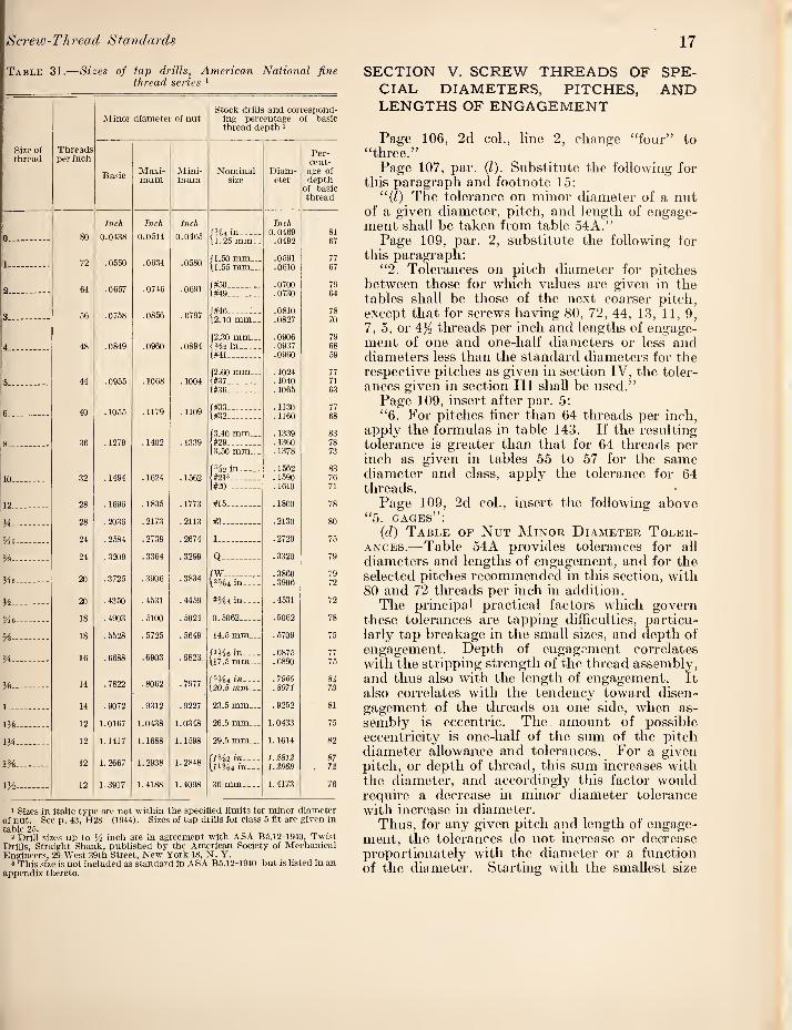
Screw-Thread Standards 17
Table 31.—Sizes of fap drills, American National fine thread series '
Minor diameter of nut Stock drills and correspond¬
ing percentage of basic thread depth 2
Size of thread
Threads per inch
Basic Maxi¬ mum
Mini¬ mum
Nominal size
Diam¬ eter
Per¬ cent¬ age of depth
of basic thread
80
Inch
0.0438
Inch
0.0514
Inch
0.0465
Inch 0.0469
.0492 81 67 0_ \i. 25 mm..
1 . 72 .0550 .0634 .0580 11.50 mm... 11.55 mm...
.0591
.0610 77 67
64 .0657 .0746 .0691 /#50_ .0700 79 2. ^3K4Q .0730
.0810
64
78 56 .0758 .0856 .0797
f#46 . . 3.. \2.10 mm.. .0827 70
4 —.- 48 .0849 .0960 .0894 (2..30 mm... <H2 in_
.0906
. 0937 79 68
l#41 .0960 59
F, 44 .0965 .1068 .1004 (2.60 mm... 1#37_
.1024
.1040 77 71
(#36_ .1065 63
40 .1055 .1179 .1109 (#33 . . .1130 77
6_ .1160
. 1339
.1360 8 _ 36 .1279 .1402 .1339 (3.40 mm... 1#29_
83 78
13.50 mm... .1378 73
.1562 83 in 32 .1494 .1624 .1562 (#2U_ .1590 76
(#20 _ . 1610 71
19. 28 .1696 .1835 .1773 #15_ .1800 78
Vi-
5/k
28 .2036 .2173 .2113 #3_ .2130 80
24 .2584 .2739 .2674 I_ .2720
24 .3209 .3364 .3299 Q..... . 3.320 79
fW_ .3860 .3906
79 20 .3906 .3834 in_ 72
V_ 20 .4350 .4531 .4459 25^4 in_ .4531 72
9/ig_ 18 .4903 .5100 .5024 0.5062_ .5062 78
^ _ 18 .5528 .5725 .5649 14.5 mm... .5709 75
Yi _ 16 .6688 .6903 .6823 /1H 6 in_ \17.5 mm...
.6875
.6890 77 75
%- 14 .7822 .8062 .7977 15^4 in- \S0.5 mm...
.7969
.8071 8i 73
1 _ 14 .9072 .9312 .9227 23.5 mm... .9252 81
OA- 12 1.0167 1.04.38 1.0348 26.5 mm... 1.0433 75
iVi- 12 1.1417 1.1688 1.1598 29.5 mm... 1.1614 82
1%_ 12 1.2667 1.2938 1.2848 jlA2 in_ \l1%4 in..-
i.m^ 1.2969
87
lA- 12 1.3917 1.4188 1.4098 36 mm_ 1.4173 76
1 Sizes in italic type are not within the specified limits for minor diameter of nut. See p. 4.3, H28 (1944). Sizes of tap drills for class 5 fit are given in table 25.
2 Drill sizes up to inch are in agreement with ASA B5.12-1940, Twist Drills, Straight Shank, published by the American Society of Mechanical Engineers, 29 West 39th Street, New York 18, N. Y.
3 This size is not included as standard in ASA B5.12-1940 but is listed in an appendix thereto.
SECTION V. SCREW THREADS OF SPE¬ CIAL DIAMETERS, PITCHES, AND LENGTHS OF ENGAGEMENT
Page 106, 2d col., line 2, change “four” to “three.”
Page 107, par. (1). Substitute the following for this paragraph and footnote 15;
“(1) The tolerance on minor diameter of a nut of a given diameter, pitcli, and length of engage¬ ment shall be taken from table 54A.”
Page 109, par. 2, substitute the following for this paragraph:
“2. Tolerances on pitch diameter for pitches between those for which values are given in the tables shall be those of the next coarser pitch, except that for screws having 80, 72, 44, 1.3, 11,9, 7, 5, or 4:% threads per inch and lengths of engage¬ ment of one and one-half diameters or less and diameters less than the standard diameters for the respective pitches as given in section IV, the toler¬ ances given in section III shall be used.”
Page 109, insert after par. 5; “6. For pitches finer than 64 threads per inch,
apply the formulas in table 143. If the resulting tolerance is greater than that for 64 threads per inch as given in tables 55 to 57 for the same diameter and class, apply the tolerance for 64 threads.
Page 109, 2d col., insert the following above “5. gages”;
(d) Table of Nut Minor Diameter Toler¬
ances.— Table 54A provides tolerances for all diameters and lengths of engagement, and for the selected pitches recommended in this section, with 80 and 72 threads per inch in addition.
The principal practical factors which govern these tolerances are tapping difficulties, particu¬ larly tap breakage in the small sizes, and depth of engagement. Depth of engagement correlates with the stripping strength of the thread assembly, and thus also with the length of engagement. It also correlates with the tendency toward disen¬ gagement of the threads on one side, when as¬ sembly is eccentric. The amount of possible eccentricity is one-half of the sum of the pitch diameter allowance and tolerances. For a given pitch, or depth of thread, this sum increases with the diameter, and accordingly this factor would require a decrease in minor diameter tolerance with increase in diameter.
Thus, for any given pitch and length of engage¬ ment, the tolerances do not increase or decrease proportionately with the diameter or a function of the diameter. Starting with the smallest size

18 Handbooks of the National Bureau of Standards
Table Minor diameter tolerances for internal special screw threads, classes 1, 2, and 3
Threads per
Lengths of engage¬ ment
inch
Over—
Minor diameter tolerances for thread sizes having basic major diameters
To and Above to ana incl.- 0,066 in.
Above Above Above 0.066 to 0.079 to 0.092 to 0.079 in. 0.092 in. 0.105 in.
Above Above 0.105 to 0.118 to 0.118 in. 0.131 in.
Above 0.131 to 0.151 in.
Above 0.151 to 0.177 in.
Above 0.177 to 0.203 in.
Above 0.203 to 0.233 in.
Above 0.233 to 0.281 in.
Above 0.281 to 0.344 in.
Above 0.344 to 0.406 in.
Above 0.406 to 0.469 in,
80.
64.
56.
48.
40.
36.
32.
28.
24.
20.
16.
ViD %D
UAD
VzD VzD
VAD
VzD VzD
lAD
VzD %D
lAD
YzO YzD
XAD
VzD YzD
UAD
VzD YzD mo
AD •^‘zD
lAD
AD AD
lAD
AD AD
lAD
AD AD
iy,D
AD AD
V/iD
VzD AD
IViD
AD YzD
lAD
VzD YzD
DAD
Inch 0.0027
.0041
.0049
.0049
Inch 0.0022
, 0033 .0044 .0049
Inch 0.0017
.0026
.0034
.0042
Inch 0.0013
.0020
. 0026
.0033
Inch 0.0013
.0020
.0026
.0033
Inch 0.0013
. 0020
.0026
.0033
Inch 0.0013
.0020
.0026
.0033
Inch 0.0013
.0020
.0026
.0033
Inch 0.0013
.0020
.0026
.0033
Inch 0.0013
.0020
.0026
.0033
VzD YzD
DAD
.0032
.0048
.0064
.0054
.0027
.0040
.0064
.0054
.0022 ,0033 . 0044 . 0054
.0017
.0025
. 0033
.0041
.0013
.0020
.0027
.0034
.0013
.0020
.0027
.0034
.0013
.0020
.0027 ". 0034
.0013
.0020
.0027
.0034
.0013
.0020
.0027
.0034
.0013
.0020
.0027
.0034
VzD YzD
DAD
.0038
.0067
.0062
.0062
.0033
. 0049
.0062
.0062
.0028
.0041
.0055
.0062
.0022
.0034
.0045
.0056
.0017
.0026
.0035
.0044
.0014
.0021
.0028
.0035
.0014
.0021
.0028
.0035
.0014
.0021
.0028
.0035
.0014
. 0021
.0028
.0035
.0014
.0021
.0028
.0035
VzD %D
DAD
.0040 . 0060 .0070 .0070
.0035
.0052
. 0069
.0070
.0029
.0044
.0059
.0070
.0024
.0037
.0049
.0061
.0019
.0029
.0038
.0048
.0016
.0023
.0030
.0038
.0015
.0023
.0030
.0038
.0015
.0023 ,0030 .0038
.0015
.0023
.0030
.0038
AD YzD
WzD
.0044
. 0066
. 0082
.0082
. 0039
.0058
.0077
.0082
.0033
. 0050
.0067
.0082
.0028
.0042
.0057
.0071
.0023
.0035
.0046
.0058
.0016
.0024
.0032
.0041
.0016
.0024
.0032
.0041
,0016 . 0024 .0032 .0041
VzD YzD
lAD
.0050
.0076
. 0098
.0098
.0045
.0068
.0091
.0098
.0040
. 0060
.0080
.0098
.0035
.0053
.0070
.0088
.0025
.0037
. 0050
.0063
.0020
.0030
.0040
.0049
.0019
.0029
.0039
.0049
VzD YzD
dad
.0053
. 0079
.0106
.0109
.0048
.0072
.0095
.0109
.0043
. 0064
.0085
.0106
.0032
.0049
.0065
.0081
.0022
.0033
.0044
.0055
.0022
.0032
.0043
.0052
AD AD
lAD
.0052
.0077
.0103
.0123
,0041 .0062 .0082 .0103
.0031
.0046
.0062
.0078
.0026
.0040
. 00.53
.0066
AD ■YzD WiD
.0042
.0068
.0084
.0104
. 0033
. 0050
.0066
. 0083
AD AD
iy>D
. 0055
.0083
.0110
. 01.38
.0045
.0067
.0090
.0112
AD AD
dad
AD AD
IViD
AD YzD
DAD
Inch 0.0013
. 0020
.0026
.0033
.0013
.0020
.0027
.0034
.0014
.0021
.0028
.0038
.0015
.0023
.0030
.0038
. 0016
. 0024
.0032
.0041
. 0019
.0029
.0039
.0049
.0022
.0032
.0043
.0054
.0024
.0037
.0049
.0061
.0030
.0044
.0059
.0074
. 0038
.0057
.0077
.0096
.0050
.0076
.0101
.0126
AD AD
IViD
Inch 0.0013
.0020
.0026
.0033
.0013
.0020
. 0027
.0034
.0014
.0021
.0028
.0042
.0015
.0023
.0030
.0044
.0016
.0024
.0032
.0046
.0019
.0029
.0039
.0049
.0022
.0032
.0043
.0054
.0024
.0037
. 0049
.0061
.0028 0042
.0056
.0070
.0032
.0049
.0065
.0081
.0044
.0066
.0088
.0110
.0052
.0078
.0104
.0130
Inch 0.0013
.0020
.0026
.0033
.0013
.0020
.0027
.0034
.0014
. 0021
. 0028
.0044
.0015
.0023
.0030
.0046
,0016 . 0024 .0032 .0048
.0019
.0029
. 0039
.0049
.0022
.0032
. 0043
.0054
.0024
. 0037
.0049
.0061
.0028
.0042
.0056
.0070
. 0032
.0049
.0065
.0081
.0037
.0056
.0075
.0094
.0045
.0068
.0091
.0113
. 0055
. 0083 ,0110 .0138
Inch 0.0013
.0021
.0021
.0033
.0013
.0021
.002;
.003'
.00141
.00211
.00281
.004
.00151
.0023]
. 00,3a
.0049
.00161
. 0024
.0035]
.0048
.0019
.0029
. 0039
.0049
.0022
. 0032]
.0043
.0054
.0024
.0937
.0049
. 0061'
.0028
.0042
. 005G3
.0070J
. 00321
. 0049]
.00651
.00811
.0036]
. 0054:5
.0072i
.0090]
.0039]
.00.581
. 0078 I
. 0097 ;
. 00491
.0073 '
. 0097
.0131 '
.0061 . 0092 ' .0123 ■ . 0154 ■
14.

Screw-Thread Standards 19
Table 54A.—Minor diameter tolerances for internal special screw threads, classes 1, 2, and 3—Continued
Threads per inch
Lengths of engagement
Minor diameter tolerances for thread sizes having basic m
Over— To and incl.—
Above 0.469
to 0.531 in.
Above 0.531
to 0..594 in.
Above 0.594
to 0.656 in.
Above 0.656
to 0.719 in.
Above 0.719
to 0.781 in.
Above 0.781
to 0.844 in.
Above 0.844
to 0.906 in.
Above 0.906
to 0.969 in.
Above 0.969
to 1.031 in.
Inch Inch Inch Inch Inch Inch Inch Inch Inch ( HD 0.0013 0.0014 0.0014 0.0015 0.0015 I Wd VsD .0020 . 0021 .0022 .0022 .0023
72_ IHD nn9« nn:?n nn3i
{ ihD l0034 .0039 .0042 .0042 .0042
HD .0014 .0014 .0014 .0015 .0015 0.0016 0.0016 0.0017 0.0017
I HD HD .0021 .0021 .0022 .0022 .0023 . 0024 .0025 .0025 .0025
1 HD IViD .0028 .0028 . 0029 .0030 .0031 .0032 . 0033 .0034 .0034
{ IHD .0044 .0044 .0047 .0047 .0047 . 0050 .0050 .0050 .0050
f_ HD .0015 .0015 .0016 .0016 .0016 .0016 .0017 .0018 .0018
) HD HD .0023 . 0023 . 0023 .0024 .0024 .0025 . 0025 .0026 .0027 56_ 1 HD WiD . 0030 . 0030 .0031 . 0032 .0032 .0033 .0034 .0035 .0036
1 IHD .0046 .0049 .0049 .0052 .0052 .0056 .0056 .0056 .0056
1_ HD .0016 .0016 . 0016 .0018 .0018 .0020 .0020 .0020 .0020
1 HD HD .0024 .0024 .0024 .0028 .0028 .0029 .0029 . 0029 .0029 48_ 1 HD IHD . 0034 . 0037 . 0037 . 0037 . C037 . 0039 .0039 . 0039 .0039
{ WiD .0048 .0051 .0051 .0057 .0057 .0059 . 0062 .0062 .0062
HD .0019 .0019 .0019 .0019 .0019 .0019 .0019 .0019 .0020
1 HD HD .0029 .0029 .0029 .0029 .0029 .0029 . 0029 .0029 . 0031 40__ 1 HD WiD . 0039 .0039 .0039 . 0039 . 0039 . 0041 .0041 .0041 .0041
1 \HD .0051 .0054 .0054 .0057 .0057 .0062 .0068 .0068 .0068
HD .0022 . 0022 .0022 .0022 .0022 .0022 .0022 .0022 .0022 1 HD HD .0032 .0032 .0032 .0032 .0032 .0032 . 0032 . 0032 . 0032
36-- 1 HD IHD . 0043 .0043 . 0043 .0043 .0043 . .0043 . 0043 .0043 . 0043 1 IHD .0054 .0057 .0057 .0057 .0057 . 0065 .0070 .0070 .0070
f- HD .0024 . 0024 .0024 .0024 .0024 .0024 . 0024 . 0024 .0024 1 HD HD . 0037 . 0037 .0037 . 0037 .0037 .0037 .0037 . 0037 .0037 1 HD \HD .0049 .0049 .0049 . 0049 .0049 .0049 .0049 .0049 .0049 t IHD .0061 .0061 .0061 .0061 .0061 .0065 .0070 .0070 .0070
f- HD .0028 .0028 .0028 .0028 .0028 .0028 .0028 .0028 .0028 1 HD HD .0042 .0042 .0042 .0042 .0042 .0042 .0042 . 0042 . 0042
28__- HD IHD .0056 .0056 .0056 .0056 . 0056 .0056 . 0056 .0056 . 0056 [ IHD .0070 .0070 .0070 .0070 .0070 .0070 .0070 .0070 .0070
HD .0032 .0032 .0032 . 0032 .0032 .0032 .0032 .0032 .0032 1 HD HD .0049 .0049 .0049 .0049 .0049 .0049 . 0049 .0049 .0049 1 HD IHD .0065 .0065 . 0065 .0065 . 0065 .0065 . 0065 . 0065 . 0005 1 IHD .0081 .0081 .0081 .0081 .0081 .0081 .0081 .0081 .0081
HD . 0036 .0036 . 0036 . 0036 .0036 .00.36 .0036 . 0036 .0036 1 HD HD .0054 .0054 .0054 .0054 .0054 . 0054 . 00.54 . 00.54 .0054
20_ 1 HD IHD .0072 . 0072 .0072 .0072 .0072 .0072 .0072 .0072 .0072 { IHD .0090 .0090 .0090 .0090 .0090 . 0090 .0090 .0090 .0102
HD .0038 .0038 .0038 .0038 .0038 .0038 .0038 .0038 .0038 1 HD HD .0057 .0057 . 0057 .0057 .0057 .0057 . 0057 . 0057 .0057
18-- 1 HD IHD .0076 .0076 .0076 .0076 .0076 .0076 . 0076 .0076 .0076 [ IHD .0095 .0095 .0095 .0095 .0095 . 0095 .0095 .0095 .0114
HD .0042 .0040 .0040 .0040 .0040 .0040 .0040 . 0040 .0040 1 HD HD . 0063 .0060 . 0060 .0060 . 0060 . 0060 .0060 .0060 .0060
16-- 1 HD IHD .0084 . 0080 .0080 .0080 .0080 .0080 .0080 . 0080 . 0080 [ IHD .0114 .0100 . 0100 .0100 .0100 .0100 .0100 . 0100 .0115
( HD .0055 .0048 .0042 .0042 .0042 .0042 .0042 .0042 .0042 I HD HD .0083 .0072 . 0062 .0062 .0062 . 0062 .0062 . 0062 . 0062 1 HD IHD .0110 .0096 .0083 .0083 .ooa3 .0083 . 0083 .0083 . 0083 \ IHD — .0138 .0120 . 0103 . 0103 .0103 .0103 .0103 .0103 .0115
(_ HD . 0065 . 005S .0052 .0045 .0045 .0045 .0045 .0045
12_ J HD HD .0097 .0087 .0077 .0067 . 0067 .0067 .0067 .0067 1 HD IHD .0129 .0116 .0103 . 0090 .0090 .0090 .0090 .0090 [ IHD .0101 .0145 .0129 .0112 .0112 .0112 .0112 .0127
f_.. HD .0074 .0068 . 0061 .0054 .0054 . 0054 1 HD HD .0111 .0101 .0092 .0081 .0081 .0081
10_ 1 HD IHD .0148 .0135 .0122 . 0108 . 0108 .0108 \ IHD .0185 .0169 .0152 .0135 .0135 .0135 , HD .0094 .0087 .0081 .0074 J HD HD 0140 .0130 .0121 .0111 1 HD \HD .0187 .0174 .0161 .0148 1 IHD .0234 .0218 .0201 .0180
HD .0090 1 HD HD .0135
6_ - - . 1 HD IHD .0180 \ IHD . 0226
f_ HD J HD HD 1 HD IHD [ IHD
Above 1.031
to 1.500 in.
Inch
0.0018 . 0020 .0035 .0052
.0020
.0031
.0041
.0056
. 0022
. 0033
. 0044
.0062
.0022
. 0034
. 0045
.0068
.0023
. 0035
.0046
.0072
.0024
. 0037
.0054
.0076
.0028
.0042
.0056
.0079
.0032
.0049
. 0065
.0081
.0036
.0054
.0072
.0102
.0038
.0057
. 0071)
.0114
.0040
. 0060
.0080
.0120
.0042
. 0062
.0096
.0127
. 0045
. 0067
.0090
.0131
.0064
.0081
.0108
.0135
.0063
.0101
. 0135
.0169
.0090
.0135
.0180
.0226
. 0135
. 0203
.0270
.0337
Above 1.500 to 2.0
in.
Inch
Above 2.5 to 4.5 in.
Inch
0.0022 .0033 .0044 .0062
.0024
. 0036
.0048
. 0008
.0025 0. 0025
. 0038 .0038
. 0050 . 0050
.0072 .0072
.0027 .0027
.0041 .0041
. 0054 . 0054
.0076 .0076
. 0028 .0031
.0042 .0046
.0062 . 0062
.0086 .0086
.0032 .0033
. 0049 .0049
.0065 . 0066
.0089 .0092
.0036 .0036
.0054 .0054
.0072 .0072
.0102 .0102
.0038 .0038
. 0057 .0057
.0076 .0082
.0114 .0114
.0040 .0040
. 0060 . 0060
.0080 .0085
.0123 .0126
.0042 .0042
.0062 . 0062
.0098 .0098
.0133 .0139
.0045 .0045
.0067 . 0067
.0098 .0108
.0137 .0143
.0054 . 0054
.0081 .0081
.0108 .0112
.0184 .0184
.0063 . 00i)3
.0101 .0101
.0135 . 01.35
. 0195 .0210
.0090 .0090
.0135 . 0135
.0180 .0180 .0226 . 0226
.0135 .0135
.0203 .0208
. 0270 .0270
. 0337 . 0337
Above 4.5 in.

20 Handbooks of the National Bureau of Standards
at the left of table 54A the tolerance is large, and decreases as the diameter increases, then remains constant over a considerable range, and increases in the larger diameters in accordance with the general tendency for tolerances to increase with increase in diameter. The large valnes at the left minimize tap breakage, but with short lengths of engagement the stripping strength is sacrificed to the extent that the full tensile strength of the screw is not developed. However, strength in small sizes is usually not important, but in larger sizes strength is the primary factor determining the selection of size, and smaller but adecpiate minor diameter tolerances tend to permit the selection of a smaller size than would otherwise be possible for a given strength.
The tolerances in table 54A increase with in¬ creases in length of engagement and in pitch.
The fundamental basis of table 54A is the pres¬ ent set of minor diameter tolerances established for the American National coarse and tine tlu-ead series on the basis of experience in production. That is, values in the table corresponding to stand¬ ard diameters and pitches, and lengths of engage¬ ment from yzD to lYzD, are in close agreement with the NC and NF values, with slight deviations in some cases to conform with formulas used. These formulas express curves of a General Motors Engineering Standard chart, which sub¬ divide the tolerance-diameter relationship into four zones, with a particular proportion of toler¬ ance to diameter applicable in each zone, and apply to lengths of engagement from YzD to iVzD. Tolerances for lengths of engagement less than YzD are Y2 of these, for YiD to %Z> are % of these, and for over \YzD are 1}^ times these. However, where the resulting tolerance would result in a depth of tlu-ead less than 53 percent of the basic tlu-ead depth, the values are adjusted to produce the 53 percent depth of thread. In the fourth zone, corresponding to the larger diameters at the right of the table, tolerances for lengths of engage¬ ment from YzD to lYiD are adjusted to equality with class 2 pitch diameter tolerances, and for lengths greater than IY2D to equality with class 1 pitch diameter tolerances.
Table 54A thus provides a sp'ecific internal minor diameter tolerance for any given choice of diam¬ eter, pitch, and length of engagement, which is expected to fulfill all requirements of good design.
Page 111, table 54. Omit column 12, which is replaced by table 54A.
Page 115. Delete table 58. (See reference to p. 19 to 23 herein.)
SECTION VI. AMERICAN STANDARD PIPE THREADS
This section is to be brought into agreement with ASA B2.1-1945, “Pipe Threads’’ by making the following revisions and corrections:
Throughout the section, change “American Na¬ tional” to “American Standard.” The term “American National” is thus reserved to identify the thread form specified in section HI.
Page 116. Revise the introduction to read as follows:
“The American Standard for Pipe Threads, originally known as the Briggs Standard, was formulated by Mr. Robert Briggs. For several yeai-s around 1862 Mr. Briggs was superintendent of the Pascal Iron Works of Morris, Tasker & Co., Philadelphia, Pa., and later engineering editor of the Journal of the Franldin Institute. After his death on July 24, 1882, a paper by Mr. Briggs con¬ taining detailed information regarding American pipe and pipe thread practice, as developed by him when superintendent of the Pascal Iron Works, was read before the Institution of Civil Engineers of Great Britain. This is recorded in the Excerpt Minutes, volume LXXI, Session 1882-83, part 1, of that Society.
“It is of interest to note that the nominal sizes (diameters) of pipe 10 inches and under, and the pitches of the thread were for the most part established between 1820 and 1840.
“By publishing his data, based on years of prac¬ tice, Mr. Briggs was the means of establishing definite detail dimensions. The Briggs formula did not provide for the internal threads or gaging requirements for making taper threaded joints. It established only the external thread on pipe, with no tolerance.
“In 1886 the large majority of American manu¬ facturers threaded pipe to practically the Briggs Standard, and acting jointly with the American Society of Mechanical Engineers they adopted it as a standard practice that year, and master plug and ring gages were made.
“Later, at various conferences, representatives of the manufacturers and the ASME established additional sizes, certain details of gaging, toler¬ ances, special applications of the standard and, in addition, tabulated the formulas and dimensions more completely than was done by Mr. Briggs.
This standard, in substantially the same form, has been adopted by the American Standards Association. It is published as AS.\ B2.1-1945, “Amer¬ ican Standard Pipe Threads,’’ by the ASME, 29 West Thirty-ninth Street, New York 18, N. Y. The specifications for gages are in agreement with Federal Specification GGG-P-351a, “Pipe Threads; Taper (American National).’’
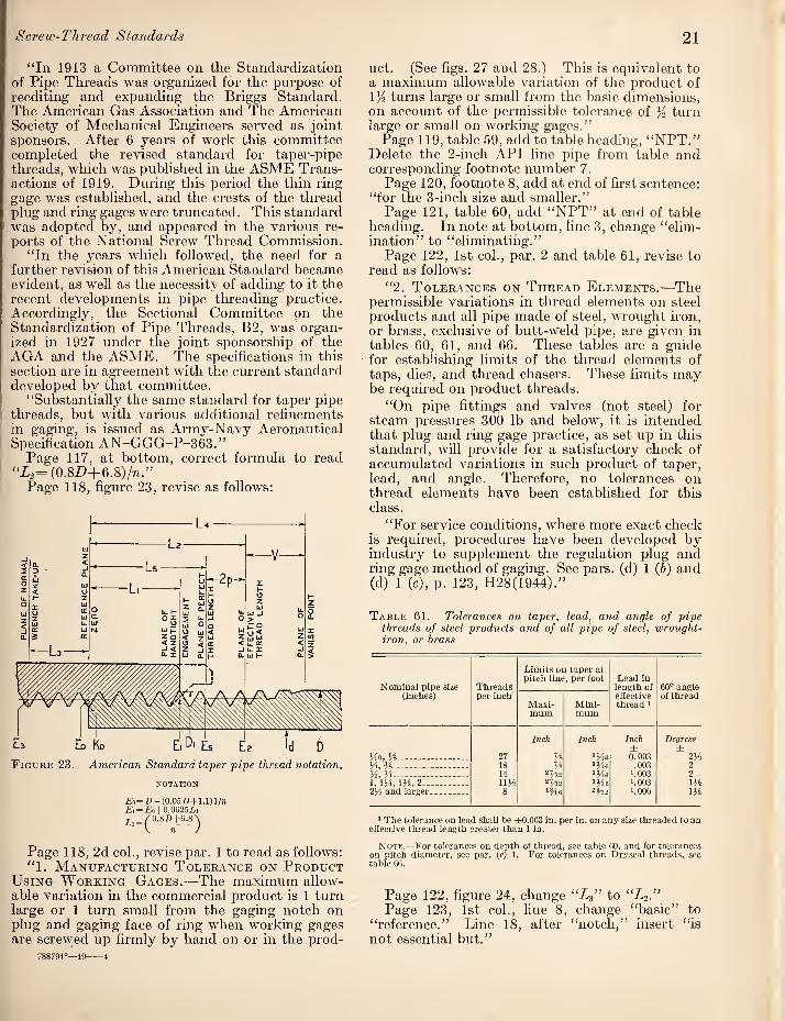
8 crew-Thread Standards 21
"In 1913 a Committee on the Standardization of Pipe Threads was organized for the purpose of reediting and expanding the Briggs Standard. The American Gas Association and The American Society of Mechanical Engineers served as joint sponsors. After 6 years of work this committee completed the revised standard for taper-pipe threads, which was published in the ASME Trans¬ actions of 1919. During this period the thin ring gage was established, and the crests of the thread plug and ring gages were truncated. This standard was adopted by, and appeared in the various re¬ ports of the National Screw Thread Commission.
“In the years which followed, the need for a further revision of this American Standard became evident, as well as the necessity of adding to it the recent developments in pipe threading practice. Accordingly, the Sectional Committee on the Standardization of Pipe Threads, B2, was organ¬ ized in 1927 under the joint sponsorship of the AGA and the ASME. The specifications in this section are in agreement with the current standard developed by that committee.
“Substantially the same standard for taper pipe threads, but with various additional refinements in gaging, is issued as Army-Navy Aeronautical Specification AN-GGG-P-363.”
Page 117, at bottom, correct formida to read “i2=(0.8D+6.8)/7i.”
Page 118, figure 23, revise as follows:
Figure 23. American Standard taper pipe thread notation.
NOTATION
a=n-(0.05Z)+i.i)i/m Ei = £:o+0.0625ii
0^80+6.8 S
n )
Page 118, 2d col., revise par. 1 to read as follows: “1. Manufacturing Tolerance on Product
Using Working Gages.-—The maximum allow¬ able variation in the commercial product is 1 turn large or 1 turn small from the gaging notch on plug and gaging face of ring when working gages are screwed up firmly by hand on or in the prod-
788794°—49-4
uct. (See figs. 27 and 28.) This is equivalent to a maximum allowable variation of the product of IK turns large or small from the basic dimensions, on account of the permissible tolerance of ){ turn large or small on working gages.”
Page 119, table 59, add to table heading, “NPT.” Delete the 2-inch API line pipe from table and corresponding footnote number 7.
Page 120, footnote 8, add at end of first sentence: “for the 3-inch size and smaller.”
Page 121, table 60, add “NPT” at end of table heading. In note at bottom, line 3, change “elim¬ ination” to “eliminating.”
Page 122, 1st col., par. 2 and table 61, revise to read as follows:
“2. Tolerances on Thread Elements.—The permissible variations in thread elements on steel products and all pipe made of steel, wrought iron, or brass, exclusive of butt-weld pipe, are given in tables 60, 61, and 66. These tables are a guide for establishing limits of the thread elements of taps, dies, and thread chasers. These limits may be required on product tlu-eads.
“On pipe fittings and valves (not steel) for steam pressures 300 lb and below, it is intended that plug and ring gage practice, as set up in this standard, will provide for a satisfactory check of accumulated variations in such product of taper, lead, and angle. Therefore, no tolerances on thread elements have been established for this class.
“For service conditions, where more exact check is required, procedures have been developed by industry to supplement the regulation plug and ring gage method of gaging. See pars, (d) 1 (6) and (d) 1 (c), p. 123, H28(1944).”
Table 61. Tolerances on taper, lead, and angle of pipe threads of steel products and of all pipe of steel, wrought- iron, or brass
Nominal pipe size Threads
Limits on taper at pitch line, per foot Lead in
length of effective thread ‘
60° angle (inches) per inch
Maxi¬ mum
Mini¬ mum
of thread
He, H--- - - . 27
Inch
%
Inch
iHe
Inch ± 0.003
Degrees' ±
2H H, H__ 18 ‘He .003 2 H, H_ 14 ‘He 1.003 2 1, IH, IH, 2_ IIH 2%2 ‘He 1.003 m 2H and larger. 8 iMe 1.006 m
' The tolerance on lead shall he ±0.003 in. per in. on any size threaded to an effective thread length greater than 1 in.
Note.—For tolerances on depth of thread, see table 60, and for tolerances on pitch diameter, see par. (c) 1. For tolerances on Dryseal threads, see table 66.
Page 122, figure 24, change to “L2.” Page 123, 1st col., line 8, change “basic” to
“reference.” Line 18, after “notch,” insert “is not essential but.”
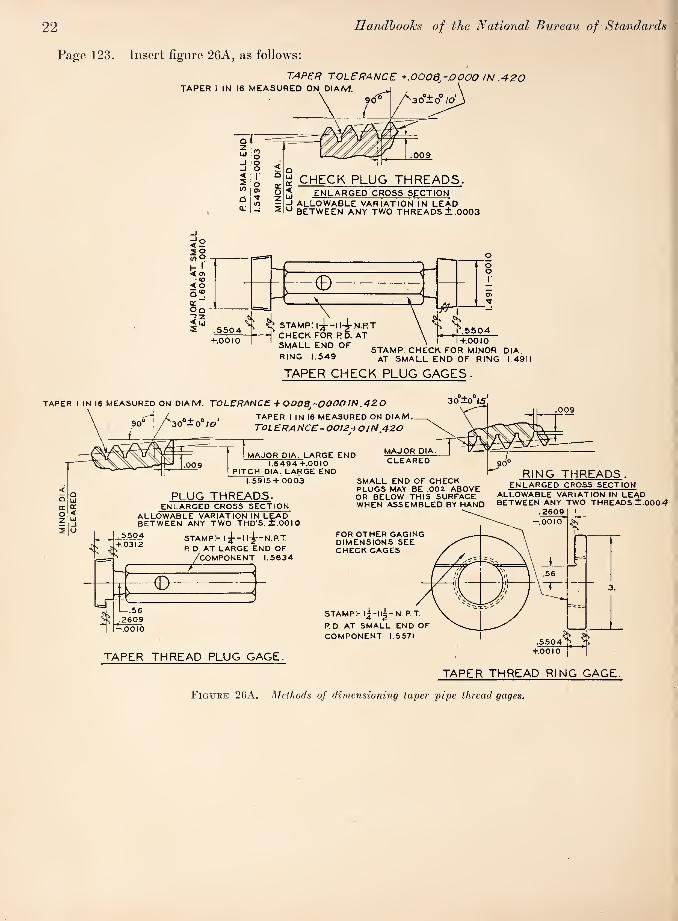
MIN
OR
DIA
CL
EA
RE
D
22 Handbooks of the National Bureau of Standards
Page 123. Insert figure 26A, as follows:
TAPER tolerance +.0008^-.0000 IN .420 TAPER 1 IN 16 MEASURED ON DIAM,
T z 2 i
^ CHECK PLUG THREADS. ENLARGED CROSS SfICTION
-1 ALLOWABLE VARIATION IN LEAD BETWEEN ANY TWO THREADS ± .0003
f.OOlO
^ stamp: l-^-ll-^N.PT
CHECK FOR RD. AT
SMALL END OF
RING 1.549
+.0010
stamp: CHECK FOR MINOR AT SMALL END OF RING
TAPER CHECK PLUG GAGES.
TAPER I IN 16 MEASURED ON DIAM. TOLERANCE -L 0008^-0000 IN .4ZO
TAPER I IN 16 MEASURED ON DIAM.
tolerance-0012+0 IN.420 30 -Co lO
.009
MAJOR DIA. LARGE END 1.6494+.0010
PITCH DIA. LARGE END
1.5915+0003
PLUG THREADS. ENLARGED CROSS SECTION
ALLOWABLE VARIATION IN L^D BETWEEN ANY TWO THD’S. ±.0010
stamp:- i^-ii-^-n.rt.
P D AT LARGE END OF Component 1.5634
TAPER THREAD PLUG GAGE.
SMALL END OF CHECK PLUGS MAY BE .002 ABOVE OR BELOW THIS SURFACE WHEN ASSEMBLED BY HAND
FOR OTHER GAGING DIMENSIONS SEE CHECK GAGES
RING THREADS. ENLARGED CROSS SECTION
ALLOWABLE VARIATION IN LEAD BETWEEN ANY TWO THREADS ±.000>f
.2609
■4 "i-N PT
P D. AT SMALL END OF
COMPONENT 1.5571
TAPER THREAD RING GAGE.
Figure 26A. ]\Iethods of dimensioning taper pipe thread gages.
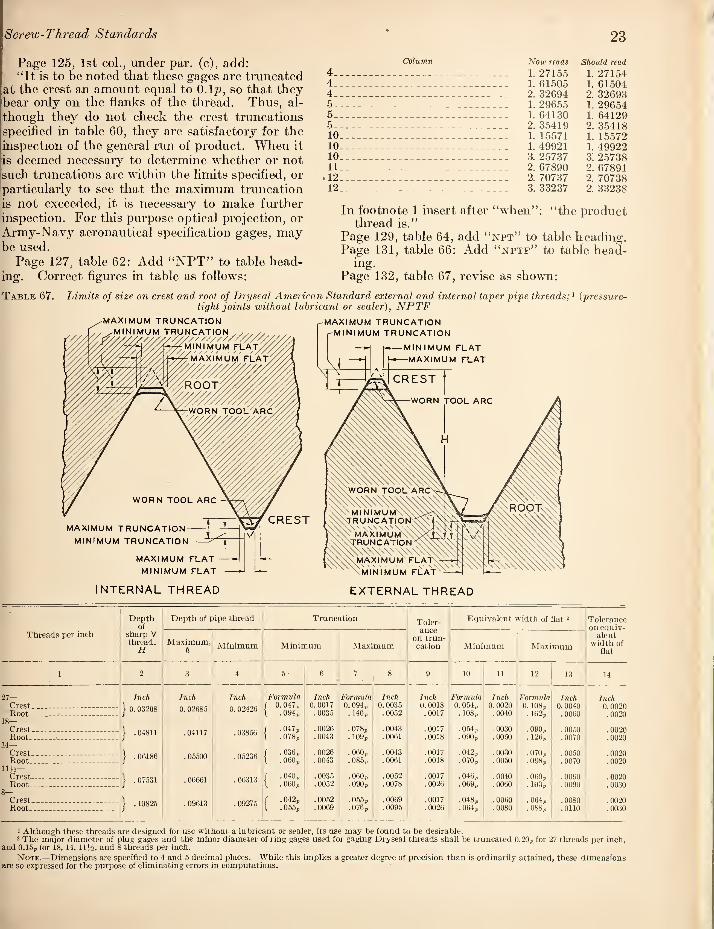
Screw-Thread Standards 23
Page 125, 1st col., under par. (c), add: “It is to be noted that these gages are truncated
at the crest an amount equal to O.lp, so that they bear only on the flanks of the thread. Thus, al¬ though they do not check the crest truncations specified in table 60, they are satisfactory for the inspection of the general run of product. When it is deemed necessary to determine whether or not such truncations are within the limits specified, or particularly to see that the maximum truncation [is not exceeded, it is necessary to make further inspection. For this purpose optical projection, or Army-Navy aeronautical specification gages, may be used.
Page 127, table 62: Add “NPT” to table head¬ ing. Correct figures in table as follows:
Table 67. Limits of size on crest and root of Dryseal Ameri tight joints without lu
Column Now reads Should read
4- 1. 27155 1. 27154 4- 1. 61505 1. 61504 4 - 2. 32694 2. 32693 5 - 1. 29655 1. 296.54 5- 1. 64130 1. 64129 5-_- 2.35419 2.35418 10_ 1. 15571 1. 15572 10_ 1. 49921 1. 49922 10 _ 3. 25737 3. 2.5738 11 _ 2.67890 2.67891 .12_ 2.70737 2.70738
12 _._ 3.33237 2.33238
In footnote 1 insert after “when”: “the product thread is.”
Page 129, table 64, add “npt” to table heading. Page 131, table 66: Add “nptf” to table head¬
ing. Page 132, table 67, revise as shown:
Standard external and internal taper pipe threads A {pressure- ant or sealer), NPTF
MAXIMUM TRUNCATION U I M I hJl I I 1,4 “TDI I M/-
MAXIMUM TRUNCATION
r-MINIMUM TRUNCATION
/ \
-MINIMUM FLAT
—MAXIMUM FLAT
MAXIMUM TRUNCATION-
MINIMUM TRUNCATION
MAXIMUM FLAT
MINIMUM FLAT
INTERNAL THREAD EXTERNAL THREAD
Depth of
Depth of pipe thread Truncation Toler- Equivalent width of flat 2 Tolerance
on equiv¬ alent
width of flat
Threads per inch sharp V thread.
H Maximum,
h Minimum Minimum Maximum on trun¬ cation Minimum Maximum
1 2 3 4 5- 6 7 8 9 10 11 12 13 14
27— Inch Inch Inch Formula Inch Formula Inch Inch Formula Inch Formula Inch Inch Crest,_ __ --- - --- } 0.03208 0.02685 0.02426
1 0.047p 0.0017 0. 094p 0. 0035 0. 0018 0. 054p 0. 0020 0.108p 0.0040 0.0020 Root _ --- - --
18— Crest_ Root. - -- -- -
14— Crest -- - -- --- Root .. _ -- ---
Ill's- Crest- - Root_ -- -
1 .094p .0035 . 140p .0052 .0017 . 108p .0040 . 162p .0060 .0020
1 .04811 .04117 .03856 f .047p \ .078p
.0026
.0043 . 0/8p . 109p
.0043
.0061 .0017 .0018
.054p
.090p .0030 .0050
.090p
. 126p .0050 .0070
.0020
.0020
} .06186 .05500 .05236 / .036p \ .060p
.0026
.0043 .060p .085p
.0043
.0061 .0017 .0018
.042p
.070p .0030 .0050
.070p
.098p .0050 .0070
.0020
.0020
J .07531 .06661 .06313 / .040p 1 .060p
. 0035
.0062 .060p .090p
.0052
.0078 .0017 .0026
.046p
.009p .0040 .0060
. 069p
. 103p .0060 . 0090
.0020
.0030
Crest--- Root- - .-
} .10825 .09613 .09275 r . 042p 1 .055p
.0052
.0009 .055p .076p
. 0069
.0095 .0017 .0026
.048p
. OtHp .. 0060 .0080
.064p
.088p .0080 .0110
.0020
.0030
1 Although these threads are designed tor use without a lubricant or sealer, its use may be found to be desirable. 2 The major diameter of plug gages and the minor diameter of ring gages used for gaging Dryseal threads shall be truncated 0.20p for 27 threads per inch,
and 0.15p for 18, 14, 11J4, and 8 threads per inch.
Note.—Dimensions are specified to 4 and 5 decimal places. While this implies a greater degree of precision than is ordinarily attained, these dimensions are so expressed lor the purpose of eliminating errors in computations.

24 Handbooks of the National Bureau of Standards
Page 135, table 70, add to table heading,' “npsc.”
Page 136, table 71, add to table heading,i “npsf.”
Page 136 table 72, add to table heading,: “npsm,” and insert the following illustration:
Page 133, table 68, add “nptr” to table heading. Page 134, table 69, revise figures in table as
follows: Column Now reads Should read
9 _ __ 0. 36 0. 357 9 .43 .435 9 _ .81 . 812 9 .94 .937 11 1.31 1.312 11 1.44 1.437
Page 136, last sentence of text, revise to read: “Major and minor diameters have been calculated on the basis of a truncation of 0.1^?, to provide no interference at crest and root when product is gaged with gages made in accordance with par.
(c) 4, below.” Page 137, add at end of text: “Major and minor
diameters have been calculated on the basis of a truncation of O.lp.”
On page 137, table 73, add to table heading, “npsl,” and insert the above illustration, as indi¬ cated for table 72.
SECTION VII. AMERICAN NATIONAL HOSE-COUPLING AND FIRE-HOSE COUPLING THREADS
Page 140, 2d col. of text, add to end of sentence above “Examples:—” “to be made up with stand- ared pipe threads.”
Page 140, table 74, insert as 2d col., heading “Identification symbol.” Insert as symbols “NH’, for first three items, and “NPSH” for remaining six items. Make corresponding insertions in tables 76, 77, and 78, with symbol “NH” for fire¬ hose threads.

Screw-Thread Standards 25
Page 141, table 75, add to table heading “NH.” Page 144, table 78, revise illustration to show truncated tkreads, thus:
Page 145, table 79, add to table heading “NH.” Pages 146, 147, tables 80 and 81, in headings
for 2d, 3d, and 4th columns insert “NH,” and for 5th column insert “NPSH.”
SECTION VIII. MISCELLANEOUS STAND¬ ARDIZED PRODUCT THREADS OF AMERICAN NATIONAL FORM, OR AMERICAN STANDARD PIPE THREAD FORM (PAGE 148)
1. GAS CYLINDER VALVE THREADS
The valves for cylinders containing compressed gases embody several screw threads, namely: (1) The outlet connection, (2) the neck, or valve to cylinder connection, (3) the safety device cap or plug, and (4) the various threads associated with the valve mechanism. Wliile the practice for all of these threads is fairly well established, only the outlet threads (1) have been fully stand¬ ardized.
(a) OUTLET CONNECTIONS.
The threads for valve outlets were not speci¬ fically defined in the past and their form, toler¬ ances, and sizes varied considerably in practice. Such threads were not officially recorded by the industry but were simply made in accordance with the best understanding and judgment of various manufacturers and users who usually handled either the cylinder with its valve, and not the connecting equipment, or the other way around. This separation of interests at the valve outlet caused wide discrepancies as compared, for ex¬ ample, with a special thread on a pipe union where the entire fitting is made as one unit by one manu¬ facturer.
The Compressed Gas Manufacturers’ Associa¬ tion, Inc., had had valve outlet standards for industrial and medical oxygen for a good many years, revising them from time to time to bring
them closer to National practice. Likewise, the Chlorine Institute had set up its standard for chlorine some time ago.
The Valve Thread Standardization Committee of the Compressed Gas Manufacturers’ Associa¬ tion, working in conjunction with federal services and other interested groups, was given a splendid opportunity during the late war to study valve outlets, especially those for federal services which were made and inspected to strict specifications. The study resulted in a closer definition and ap¬ preciation of each outlet, and in a more balanced relationship of the many outlets to each other to achieve the utmost in safety. In Januaiy, 1946, the findings and formulatetl standards, upon wliich the federal data contained herein arc based, ap¬ peared in the Committee’s report “Standard Compressed Gas Cylinder Valve Outlets.”
Either a single gas, or else several gases which create no hazard if interchanged, are assigned to the same outlet. With the exception of outlets having taper pipe threads which seal at the threads, each outlet proGdes for a seat and nipple which make a gas-tight joint against leaks and also provides for 14-pitch American National form screw threads not in the regular series. These threads do not seal but merely hold the nipple against its seat.
The threads on the valves fall into four divisions, right-hand or left-hand (IIH or LH) and external or internal (EXT or INT). These four basic divisions are so vital to prevent undesirable cross-connecting that the full designation of each gas-outlet thread inclufles the terms RH or LH and EXT or INT. In general, where practicable, right-hand threads are used for nonfuel or for water-pumped gases, and left-hand threads for fuel or for oil-pumped gases. Left-hand threads are identified by a groove across the corners of the hexagon nut.
The nominal diameters of the threads in each division are spaced far enough apart so they will

26
not engage with the thread of an adjoining size. An allowance (minimum clearance) of 0.0050 inch between the matijig parts is established to provide the desired looseness of fit at the threads and to assure uninterrupted interchangeability between products of different manufacturers, who lacked a common standard in the past. The tolerances are in the direction of greater looseness and are determined on the basis of NS-3 data, except for the major diameter of the external thread where the tolerance is 0.0050 inch instead of 0.0098 inch.
Handbooks of the National Bureau of Standards
Screw threads meeting the above specifications bear the designation NGO, National Gas Outlet, as a separate and distinct symbol for valve outlet threads. This symbol was suggested and desig¬ nated by the Interdepartmental Screw Thread Committee, representing the Federal agencies, to provide for the peculiar needs of the industry. The designation NGO (Cl) applies to the alternate chlorine thread which has been used successfully without change for many years.
The data in table 85 list the industrial and
Table 85.— U. S. A. compressed gas cylinder valve outlet threads
Number
1
1 _ .Acetylene, standard.. 2 _ Acetylene, alternate >. 3 _ Air, water-pumped... 4 _ Air, oil-pumped_
Gas
5A, 5B
6..
jAmmonia, anhydrous, standard
Ammonia, anhydrous, alternate '
7 _ Argon, water-pumped. 8 _ Argon, oil-pumped_ 9 _ Butadiene..
Thread of valve
3
0.885"-I4NGO-LH-INT_ .825"-14NG0-Rn-EXT_ .965"-14NG0-RH-INT_ .9fi.V'-14NG0-LH-INT_ %"-18NPT-RH-INT, or_ ^'M4NPT-RH-INT_ 3i"-18NPT-RH-INT, with...
1"-14NF-2LH-EXT for nut. .96,5"-14NGO-RHUNT_ .965"-14NGO-LH-INT.. . .885"-14N G O-LH-INT_
Mating thread
4
0.8S0"-14N G 0-LH-E X T. .8.30"-14NGO-RH-INT. .9fi0"-14NGO-RH-EXT. .9fin"-14NGO-LH-EXT. ?i"-18NPT-RH-EXT, or
}-^"-14NPT-RH-EXT. ?V'-18NPT-RH-EXT. with
]"-14Nr-2LH-INT for nut. .9BO"-14NGO-RH-EXT. .96n"-14NGO-LH-EXT. .880"-14NGO-LH-EXT.
10.
11.
12.
13 14.
Butane, standard_ Butane, No. 1 alternate i. Butane, No. 2 alternate '. Carbon dioxide, standard. Carbon dioxide, medical.
l.l_ 16_ 17_
Chlorine, standard.. Chlorine, alternate '. Cyclopropane_
18 _ Dichlorodifluoro-methane 19 _ Ethane..
.88.5"-! 4NG O-LH-INT_
.825"-14NGO-LH-EXT_ ..
.82,r'-14NGO-RH-EXT_
.825"-14NG0-RH-EXT__ Standard medical gas flush outlet for yoke.
1.03n"-14NGO-RH-EXT_ 1.034"-14NGO(C1)-RH-EXT_ Standard medical gas flush outlet for yoke.
1.030"-14NGO-RH-EXT_ n.825"-14NGO-LH-EXT_
,880"-14NGO-LH-EXT. .830"-14NGO-LH-INT. .830"-14NGO-Rn-INT. .830"-14NGO-RH-INT.
Standard medical gas flush outlet for yoke.
1.035"-14NG O-RH-INT. 1.0.3.6"-14NGO(C1)-RH-INT. Standard medical gas flush outlet for
yoke. 1.035"-14NGO-RH-INT. 0.830"-14NGO-LH-INT.
20.
21.
22.
Ethyl chloride_ Ethylene, industrial and medical. Ethylene, medical_
23. 24. 25 26.
Ethylene oxide, standard.... Ethylene oxide, alternate >. Helium, water-pumped, standard Helium, medical..
27. 28. 29.
Helium, oil-pumped, standard.. Helium, oil-pumped, alternate <. Hydrogen___
.825"-14NGO-RH-EXT_
.825"-14NGO-LH-EXT_ Standard medical gas flush outlet for yoke.
.885"-14NG O-LH-INT_
.825"-14NGO-LH-EXT_
.965"-14NGO-RH-INT_ Standard medical gas flush outlet for yoke.
.965''-! 4NG O-LH-INT____
.825"-14NGO-LH-EXT_
.826"-14NG O-LH-EXT_
.830"-14NGO-RH-INT.
.8.30"-14NGO-LH-INT. Standard medical gas flush outlet for
yoke. .880"-14NGO-LH-EXT. .830''-14NGO-LH-INT. .960"-14NGO-RH-EXT.
Standard medical gas flush outlet for yoke.
.9nO"-14NGO-LH-EXT.
.830"-14NGO-LH-INT.
.830"-14NG O-LH-INT.
30. 31 32. 33 .34. 3.5. 36. 37. 38.
Isobutane, standard_ Isobutane, alternate '_ Methane_ Methyl chloride, standard.. Methyl chloride, alternate > Nitrogen, water-pumped... Nitrogen, oil-pumped_ Nitrous oxide, standard_ Nitrous oxide, medical_
.88.5"-14NGO-LH-INT_
.82,5''-]4NGO-LH-EXT_
.825" -14NGO-LH-EXT_ 1.030"-14NGO-RH-EXT___ }4"-14NPT-RH-EXT___ .96.5"-14NGO-RH-INT__ .96,5"-14NGO-LH-INT_ .825"-14NGO-RH-EXT_
Standard medical gas flush outlet for yoke.
.880"-14NGO-LH-EXT.
.830"-14NGO-LH-INT.
.830"-14NGO-Ln-INT. 1.035"-14NGO-RH-INT.
H"-14NPT-RH-INT. .960"-14NGO-RH-EXT. .960"-14NGO-LH-EXT. .830"-14NG O-RH-INT.
Standard medical gas flush outlet for yoke.
39. 40. 41.
Oxygen, industrial and medical. Oxygen, medical ^_ Oxygen, medical_
42. 43. 44. 45. 46. 47. 48.
Propane, standard_ Propane, No, 1 alternate '. Propane, No. 2 alternate >. Propylene, standard_ Propylene, alternate i_ Sulfur dioxide, standard... Sulfur dioxide, alternate
.903"-14NGO-RH-EXT_
.825"-14NGO-RH-EXT_ Standard medical gas flush outlet for yoke_
.885"-14NG O-LH-INT___
.82.5"-14NGO-LH-EXT_
.825"-14NGO-RH-EXT___
.885"-14NGO-LH-INT__
.825"-14N G O-LH-E X T__ 1.0.30"-14NGO-Rn-EXT__ i4"-14NPT-RH-EXT_...
.908"-14NG O-RH-INT.
.830"-14NGO-RH-INT. Standard medical gas flush outlet for
yoke. .880"-14NGO-LH-EXT. .830"-! 4NG O-LH-INT. .8.30"-14NG O-RH-INT. .880"-14NGO-LH-EXT. .830"-14NOO-LH-INT.
1.035"-14NGO-RH-INT. 34"-14NPT-Rn-INT.
> Alternate outlet dimensions are shown to indicate valve outlet threads widely used by industry in addition to the approved standards. Federal services shall not specify alternate outlet dimensions. In areas where gases cannot be readily procui'ed commercially in cylinders equipped with valves complymg with these standards, cylinders equipped with valves complying with the alternate standards may be accepted, provided authority to do so is specifically granted by the Government department concerned. Alternates may be used only dm’ing a limited transition period.
2 Outlet 5A is standard for Federal services. 3 Outlet 40, extensively used by the medical profession for oxygen, is not authorized for Federal services. ^ Outlet 28 is past practice and is authorized for interim use but not tor new procurement by Federal services.
Note.—Details of vah’e outlets and comiections are published by the Compressed Gas Manufacturers’ Association, Inc., 11 West Forty-second Street, New York 18, N. Y.

Screw-Thread Standards 27
medical gases with the threads used on the respective valves and on their mating parts, while the data in table 85A give complete tlrread information for the use of toolmakers, manufac¬ turers, and inspectors. Table 85B is a rearrange¬ ment of the data in the first three columns of table 85 to show interchangeability among gases and outlet tlu-eads. Attention is directed to footnote 1 of table 85 relative to alternates, which are to be eliminated as rapidly as possible.
For a complete and detailed design of each gas outlet and its connecting parts, see “Standard Compressed Gas Cylinder Valve Outlets” pub¬ lished by the Compressed Gas Manufacturers’ Association, Inc., 11 West Forty-second Street, New York 18, N. Y.
Gages for “NGO” threads specified in table 85A shall be made in accordance with the gage specifi¬ cations in section III. Gages for the “NPT” threads listed in table 85 shall be made in accord¬ ance with the gage specifications in section VI.
(b) INLET CONNECTIONS
The screw threads on the inlet connections on the valve and in the cylinder neck are taper pipe threads subject to very high pressures and are longer than the Ametican Standard taper pipe tlneads but otherwise conform to the dimensions given in tables 59 and 60. Proper control of the dimensions within the tolerances specified for all elements of the tlmeads is necessary to prevent leakage and requires gages of special design.
[The remainder of this subsection is in iirocess of being revised.]
Further corrections: Page 151, table 86 column 3, next to last line,
change ‘T"-14NPT” to NPT.”
Page 152, table 87B, in right-hand view of plug, delete diameter D and show diameter Ki at notch B located at length Li from end. Page 154, footnote 24, insert “of” after “dimensions.”
Table 85A. Limits of size of U. S. A. compressed gas cylinder valve outlet threads series NGO
Symbol (designation of thread)
External thread Internal thread
Major diameter Pitch diameter Minor
diameter Minor diameter Pitch diameter
Major diameter
Max Min Max Min Max Min Max Min Max Min
1 2 3 4 5 6 7 8 9 10 11
.745"-I4NGO“?S-EXT_ Inches 0. 7450
Inches 0. 7400
Inch 0. 6986
Inch 0.6950
Inch 0. 6574
Inch Inch Inch Inch Inches
-Jutl
.750"-14NGO”lh-INT.. 0. 6727 0. 6804 0. 7036 0. 7072 0. 7500
.825"-14NG0”?5-EXT . .8250 .8200 .7786 .7750 .7374 -L/xl
.830"-14NG 0~?§-INT... _ .7527 . 7604 .7836 .7872 .8300 -L/xl
.880"-14NGO-LH-EXT.. _ . .8800 .8750 .8336 .8300 .7924
.885"-14NGO-LH-INT .. .8077 .8154 .8386 .8422 .8850
.9n3"-14NGO-RH-EXT . .9030 .8980 .8566 .8530 .8154
.908"-14NGO-RH-INT... .. .8307 .8384 .8616 .8652 .9080
.960"-14NGO“?§-EXT . .9600 .9550 .9136 .9100 .8724 — L/xl
.965"-14NG0“P5-INT..... .8877 .8954 .9186 .9222 .9650 - l_/xl
I.n30’'-14NGO“?S-EXT .. 1.0300 1.0250 .9836 .9796 .9424 -L/±l
1.035"-14NGO“Pfl-INT __ .9577 .9654 9886 .9926 1 0350 — IjiJ.
1 034"-14NGO(C1)-RH-EXT 1.0340 1. 0300 .9835 .9795 .9330 1.035"-14NGO(C1)-RH-INT_ .9400 .9530 .9845 .9885 1.0350

28 Ilandboohs of the National Bureau of Standards
Table 85B. Correlation of threads of valve and gases to show interchangeability
Thread of valve Num¬
ber Gas
0.825-14NGO-RH-EXT-
12 13 20 37 40 44
Acetylene, alternate. Butane, No. 2 alternate. Carbon dio.xide, standard. Ethyl chloride. Nitrous oxide, standard. Oxygen, medical. Propane, No. 2 alternate.
0.82.5-14NGO-LH-EXT.
11 19 21 24 28 29 31 32 43 40
Butane, No. 1 alternate. Ethane. Ethylene, industrial and medical. Ethylene oxide, alternate. Helium, oil-pumped, alternate. Hydrogen. Isobutane, alternate. Methane. Propane, No. 1 alternate. Propylene, alternate.
n.885-14NGO-LH-INT
0.903-14NGO-RH-EXT
0.965-14NGO-RH-INT.
1 9
10 23 30 42
Acetylene, standard. Butadiene. Butane, standard. Ethylene oxide, standard. Isobutane, standard. Propane, standard. Propylene, standard.
39 Oxygen, industrial and medical.
3 Air, water-pumped. 7 Argon, water-pumped.
2.'i Helium, water-pumped, standard. 35 Nitrogen, water-pumped.
0.965-14NGO-LH-INT
4 8
27 36
Air, oil-pumped. Argon, oil-pumped. Helium, oil-pumped, standard. Nitrogen, oil-pumped.
1.030-14NGO-Rn-EXT
{15 Chlorine, standard. 18 nichlorodifluoro-methane. 33 Methyl chloride, standard. 47 Sulfur dioxide, standard.
1.034-14NGO(Cl)-RH-EXT 16 Chlorine, alternate.
?^"-18NPT-RII-INT.
j^"_14NPT-Rn-EXT
5A 6
34 48
Ammonia, anhydrous, standard. Ammonia, anhydrous, alternate.
Methyl chloride alternate. Sulfur dio.xide, alternate.
.H"-14NPT-RH-1NT 5B Ammonia, anhydrous, standard.
Standard medical gas flush outlet for yoke.
14 17 22 26 38 41
Carbon dioxide, medical. Cyclopropane. Ethylene, medical. Helium, medical. Nitrous oxide, medical. Oxygen, medical.
SECTION X. ACME THREADS
The American War Standard ASA Bl.5-1945, "Acme Threads,” of the American Standards Asso¬ ciation, is being considered by the ASA Sectional Committee Bl for adoption as an American Standard. It is to be anticipated that there will be some revisions.
The following revisions and corrections to be made in this section are necessary to bring it into substantial agreement with the American War Standard as published, and with the specifications for gages in section III of this supplement:
Page 158, 2d col., at end of “1. General and
Historical,” insert: "While threads for valve operation may be made
to this standard, the application is higlily special¬
ized and these data should not be used without consultation with the valve manufacturer.”
Page 159, 2d col., 3d sentence under table, change to read: "It is suggested that screws and nuts of the same class be used together for either general purpose or centralizing assemblies.”
Page 159, 2d col., last line: Delete remainder of paragraph and substitute: "Classes 5C and 6C screws and nuts can be used interchangeably, but if a class 5C nut is used with a class 6C screw, the available backlash is less than when used with a class 5C screw.”
Page 160, 2d col., par. No. 4, line 6, change “column 8” to "column 4.” (Same correction applies to ASA Bl. 5-1945.)
Page 161, 2d col., line 7 from bottom, change “BD” to “B.”
Page 174, table 98, column headed %, change ".2731” to ".2730.”
Pages 177-179, revise the text to read as follows:
7. GAGES FOR ACME THREADS
Gages representing both extreme product limits, or adequate gaging instruments for thread ele¬ ments, are necessary for the proper inspection of Acme screw threads. The dimensions of "go” and "not go” gages should be in accordance with the principles: (a) that the maximum-metal limit, or "go”, gage should check simultaneously as many elements as possible, and that a minimum-metal limit or "not go” thread gage can effectively check but one element; and (b) that permissible varia¬ tions in the gages be kept within the extreme product limits.
(a) GAGE TOLERANCES
Tolerances for the tliread elements of "go” and "not go” thread gages for Acme threads are given in tables 12, p. 39, and 100, p. 179, H28(1944).
1. Tolerances on Pitch Diameter.—The pitch diameter tolerances for gages for class 2 screws and nuts are given in table 100, column 2, and for gages for classes 3, 4, 5, and 6 screws and nuts, in table 100, column 3.
2. Tolerances on Major and Minor Diam¬
eters.—^Tlie major and minor diameter tolerances for Acme thread gages are given in table 100, column 4. These are applicable to all gages except the "go” and "not go” thread plug gages for major diameter of all classes of centralizing nuts, and for "go” and "not go” plain ring or snap gages for major diameter of centralizing screws. For these gages the tolerances are class Z, as given in table 12, p. 39, H28(1944).
3. Tolerances on Lead.—The variation in lead of all Acme thread gages for classes 3, 4, 5, and 6 product shall not exceed 0.0002 inch between any two threads not farther apart than one inch. However, the cumulative error in lead shall not exceed 0.0003 inch for gages with a length over 1
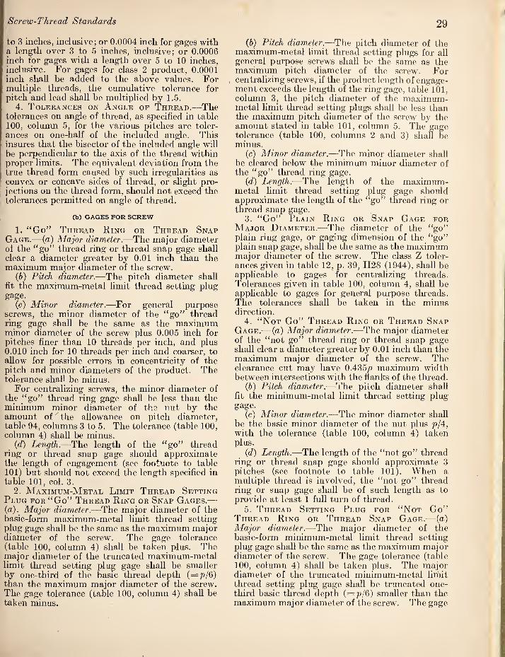
Screw-Thread Standards 29
to 3 inches, inclusive; or 0.0004 inch for gages with a length over 3 to 5 inches, inclusive; or 0.0006 inch for gages with a length over 5 to 10 inches, inclusive. For gages for class 2 product, 0.0001 inch shall be added to the above values. For multiple threads, the cumulative tolerance for pitch and lead shall be multiplied by 1.5.
4. Tolerances on Angle of Thread.—-The tolerances on angle of thread, as specified in table 100, column 5, for the various pitches are toler¬ ances on one-half of the included angle. This insures that the bisector of the included angle will be perpendicular to the axis of the thread within proper limits. The equivalent deviation from the true thread form caused by such irregularities as convex or concave sides of thread, or slight pro¬ jections on the tlrread form, should not exceed the tolerances permitted on angle of thread.
(b) GAGES FOR SCREW
1. “Go” Thread Ring or Thread Snap
Gage.— {a) Major diameter.—The major diameter of the “go” thread ring or thread snap gage shall clear a diameter greater by 0.01 inch than the maximum major diameter of the screw.
{b) Pitch diameter.—The pitch diameter shall fit tbe maximum-metal limit thread setting plug gage.
(c) Minor diameter.—For general purpose screws, the minor diameter of the “go” thread ring gage shall be the same as the maximum minor diameter of the screw plus 0.005 inch for pitches finer than 10 tlneads per inch, and plus 0.010 inch for 10 threads per inch and coarser, to allow for possible errors in concentricity of the pitch and minor diameters of the product. The tolerance shall be minus.
For centralizing screws, the minor diameter of the “go” thread ring gage shall be less than the minimum minor diameter of the nut by the amount of the allowance on pitch diameter, table 94, columns 3 to 5. The tolerance (table 100, column 4) shall be minus.
{d) Length.—The length of the “go” thread ring or thread snap gage should approximate the length of engagement (see footnote to table 101) but should not exceed the length specified in table 101, col. 3.
2. Maximum-Metal Limit Thread Setting
Plug for “Go” Thread Ring or Snap Gages.—■ {a). Major diameter.—The major diameter of the basic-form maximum-metal limit thread setting plug gage shall be the same as the maximum major diameter of the screw. The gage tolerance (table 100, column 4) shall be taken plus. The major diameter of the truncated maximum-metal limit thread setting plug gage shall be smaller by one-third of the basic thread depth (=p/6) than the maximum major diameter of the screw. The gage tolerance (table 100, column 4) shall be taken minus.
(6) Pitch diameter.—The pitch diameter of the maximum-metal limit thread setting plugs for all general purpose screws shall be the same as the maximum pitch diameter of the screw. For centralizing screws, if the product length of engage¬ ment exceeds the length of the ring gage, table 101, column 3, the pitch diameter of the maximum- metal limit thread setting plugs shall be less than the maximum pitch diameter of the screw by the amount stated in table 101, column 5. The gage tolerance (table 100, columns 2 and 3) shall be minus.
(c) Minor diameter.—The minor diameter shall be cleared below the minimum minor diameter of the “go” thread ring gage.
(d) Length.—The length of the maximum- metal limit thread setting plug gage should approximate the length of the “go” thread ring or thread snap gage.
3. “Go” Plain Ring or Snap Gage for
Major Diameter.—The diameter of the “go” plain ring gage, or gaging dimension of the “go” plain snap gage, shall be the same as the maximum major diameter of the screw. The class Z toler¬ ances given in table 12, p. 39, H2S (1944), shall be applicable to gages for centralizing threads. Tolerances given in table 100, column 4, shall be applicable to gages for general purpose threads. The tolerances shall be taken in the minus direction.
4. “Not Go” Thread Ring or Thread Snap
Gage.^—(a) Major diameter.—The major diameter of the “not go” thread ring or thread snap gage shall clear a diameter greater by 0.01 inch than the maximum major diameter of the screw. The clearance cut may have 0.435p maximum width between intersections with the flanks of the thread.
(6) Pitch diameter.—The pitch diameter shall fit the minimum-metal limit thread setting plug gage.
(c) Minor diameter.—The minor diameter shall be the basic minor diameter of the nut plus p/4, with the tolerance (table 100, column 4) taken plus.
{d) Length.—The length of the “not go” thread ring or thread snap gage should approximate 3 pitches (see footnote to table 101). When a multiple thread is involved, the “not go” thread ring or snap gage shall be of such length as to provide at least 1 full turn of thread.
5. Thread Setting Plug for “Not Go”
Thread Ring or Thread Snap Gage.— (a) Major diameter.—The major diameter of the basic-form minimum-metal limit thread setting plug gage shall be the same as the maximum major diameter of the screw. The gage tolerance (table 100, column 4) shall be taken plus. The major diameter of the truncated minimum-metal limit thread setting plug gage shall lie truncated one- tliird basic thread depth (=7^/6) smaller than the maximum major diameter of the screw. The gage

30 Ilandbool's of the National Bureau of Standards
tolerance (table 100, column 4) shall be taken minus.
(6) Pitch diameter.—The pitch diameter shall be the same as the minimum pitch diameter of the screw, with the tolerance taken plus.
(c) Minor diameter.—The minor diameter shall be cleared below the minimum minor diameter of the “not go” thread ring gage.
{d) Length.—The length shall be at least equal to the length of the “not go” thread ring or thread snap gage.
6. “Not Go” Plain Snap Gage for Major Diameter.—The gaging dimension of the “not go” plain snap gage shall be the same as the minimum major diameter of the screw. Class Z tolerances given in table 12, p. 39, H28 (1944) shall be applicable to gages for centralizing threads. Tolerances given in table 100, column 4 shall he applicable to gages for general purpose threads. The gage tolerance shall he taken in the plus direction.
(c) GAGES FOR NUT
1. “Go” Thread Plug Gage, General Pur¬
pose Threads.—The major diameter of the “go” thread plug gage for general purpose threads shall be equal to the minimum major diameter of the nut minus 0.005 inch for pitches finer than 10 threads per inch, and minus 0.010 inch for 10 threads per inch and coarser, to allow for possible errors in concentricity of the pitch and major diameters of the product. The gage tolerance (table 100, column 4) shall be plus.
(6) Pitch diameter.—The pitch diameter shall be equal to the minimum (basic) pitch diameter of the nut, with the tolerance (table 100, columns 2 and 3) taken plus.
(c) Minor diameter.—The minor diameter shall clear a diameter less by 0.01 inch than the mini¬ mum minor diameter of the nut.
(d) Length.—The length of the “go” thread plug- gage should approximate the length of engagement (see footnote to table 101) but shall not exceed twice the nominal major diameter unless specifi¬ cally requested.
2. “Go” Thread Plug Gage for Central¬
izing Threads.^—(a) Major diameter.—The major diameter of the “go” thread plug gage for central¬ izing threads shall be the same as the minimum major diameter of the nut with a plus tolerance, class Z (table 12, p. 39, H28 (1944). Both comers at the crest shall be chamfered equally at an angle of 45°, leaving a width of flat at crest of 0.28p+ 0.00, —0.02p.
(6) Pitch diameter, minor diameter, and length.— The pitch diameter, minor diameter, and length of. gage shall be the same as those given in 1 (b), 1 (c), and 1 (d) above.
3. “Not Go” Thread Plug Gage for Pitch
Diameter of All Nuts.—(o) Major diameter.—
The major diameter of the “not go” thread plug
gage shall be equal to the maximum (basic) major diameter of the screw minus p/4, with the toler¬ ance (table 100, column 4) taken minus.
(6) Pitch diameter.— The pitch diameter shall be the same as the maximum pitch diameter of the nut, with the tolerance (table 100, columns 2 and 3) taken minus.
(c) Minor diameter.—The minor diameter shall clear a diameter less by 0.01 inch than the mini¬ mum minor diameter of the nut. The clearance cut may have 0.435p maximum width between intersections with the flanks of the thread.
(f/) Length.—The length of the “not go” thread plug gage should approximate 3 pitches (see foot¬ note to table 101). When a multiple thread is involved, the “not go” thread plug gage shall be of such length as to provide at least 1 full turn of thread.
4. “Not Go” Thread Plug Gage for AIajor
Diameter of Centralizing Nut.—The major diameter shall be equal to the maximum major diameter of the nut. The tolerance shall be class Z (table 12, p. 39, H28 (1944), taken minus. The included angle of the thread shall be 29°. The pitch diameter shall be the maximum pitch diameter of the class 4C centralizing screw (for centralizing nuts, classes 2C, 3C, and 4C) or the maximum pitch diameter of the class 6C centraliz¬ ing screw (for centralizing nuts, classes 5C and 6C), with a minus tolerance of twice that given in table 100, column 3. The crest corners shall be chamfered 45° equally to leave a central crest flat not more than 0.24p wide. The approximate depth of chamfer is 0.07p. The minor diameter shall clear a diameter less by 0.01 inch than the minimum minor diameter of the nut. The length should approximate 3 pitches (see footnote to table 101). When a multiple thread is involved, the “not go” gage shall be of such length as to provide at least 1 full turn of thread.
5. “Go” Plain Plug Gage for Minor Diam¬
eter OF Nut.—The diameter of the “go” plain plug gage shall be the same as the minimum minor diameter of the nut. The gage tolerance shall be class Z (table 12, p. 39, H28 (1944)), taken plus. The gage length shall be in accordance with Com¬ mercial Standard CS8-41, Gage Blanks, or the latest revision thereof.
6. “Not Go” Plain Plug for Minor Diam¬
eter OF Nut.—The diameter of the “not go” plain plug gage shall be the same as the maximum minor diameter of the nut. The gage tolerance shall be class Z (table 12, p. 39, H28 (1944)), taken minus. The gage length shall be in accordance with CS8-41 or the latest revision thereof.
(d) CONCENTRICITY
Methods of securing concentricity between major and pitch diameters of screw or nut must be determined for each individual application.

Screw-Thread Standards 31
Page 180, revise note under table 101 to read as follows;
Note.—The above compensation is based on a length of engagement not exceeding two diameters and on a lead error in the product not exceeding the following values (in inch):
0.0003 in length of inch or less. .0004 in length over ^2 to IVi inches. .0005 in length over to 3 inches. .0007 in length over 3 to 6 inches. .0010 in length over 6 to 10 inches.
The principles have been established in the foregoing requirements that “go” gages should approximate the length of engagement, and “not go” gages should be 3 pitches long. For reasons of economy or limitations in gage manufacture or use, it may be desirable to modify these principles to: (1) Take advantage of the economies of using standard blanks, as listed in CS8-41, wherever they may be utilized successfully. (2) Avoid too cumber¬ some ring gages as well as excessively expensive gages by limiting the length of “go” thread ring gages to maximum lengths given in column 3 above. (3) Avoid excessively cumbersome thread plug gages by limiting maximum length to 2 diameters wherever possible. (4) Take full advantage of modern equipment for producing and check¬ ing accurate leads, particularly where long engagements are involved, thus permitting the use of standard or mod¬ erate length thread plug, thread ring, or thread snap gages. Alternatively, of course, instruments might be used for checking diameters and angles independently.
Should a “go” gage shorter than the len^,h of engage¬ ment be chosen, independent means should be used to measure lead error in product. The maximum metal con¬ dition must be reduced to assure free assembly of product, if the lead error in the length of engagement, so deter¬ mined, exceeds 0.259 G, where G is the product pitch diameter allowance. The required amount of change in pitch diameter, AE, of the product (minus on external thread, plus on internal thread) accordingly is
AS=3.867(^l-^^5p,
where Lg is the length of the gage, and is the length of engagement. When instruments are used for checking diameter it is a simple matter to make this allowance. When thread plug and ring gages are used, the allowance is sometimes increased a fixed amount, as outlined in the above table. This arbitrarily reduces the tolerance on diameter.
SECTION XI. WRENCH-HEAD BOLTS AND NUTS, AND WRENCH OPENINGS
Page 181, footnote 26, add: “Stock production sizes (lengths, diameters, etc.) of regular square and hexagon head machine bolts and heavy, reg¬ ular, and light nuts are given in Simplified Prac¬ tice Recommendation R169-37, Machine, Car¬ riage, and Lag Bolts (Steel) (Stock Production Siz0s)
Page 185, table 104, col. 2, change “1.2500” to “1.8750.”
SECTION XII. ROUND UNSLOTTED HEAD BOLTS
Page 197, footnote 29, add: “Stock production sizes (lengths, diameters, etc.) of square neck car¬ riage bolts, step bolts, and elevator bolts are given
in Simplified Practice Recommendation R169-37, Machine, Carriage, and Lag Bolts (Steel) (Stock Production Sizes).”
SECTION XIH. MACHINE SCREWS, MA¬ CHINE-SCREW AND STOVE-BOLT NUTS, AND SET SCREWS
The data in this section relative to sloted ma¬ chine, cap, and set screws are, for the present, superseded by the corresponding data in American Standard ASA Bl8.6-1947, Slotted and Recessed Head Screws. A complete revision of this section is deferred until a revision, now in progress, of Federal Specification FF-S-91, Screws, Machine; (Including Screws, Set) has been completed, in order that this section and the revised Federal specifications will be in complete agreement.
SECTION XIV. SOCKET SET SCREWS, SOCKET-HEAD CAP SCREWS, AND SOCKET-HEAD SHOULDER SCREWS
The data in this section are, for the present, superseded by American Standard ASA Bl8.3-1947, Socket Head Cap Screws and Socket Set Screw's. A complete revision of this section is deferred until Federal Specifications covering these items, now in process of development, have been completed, in order that this section and the Federal Specifications will be in complete agree¬ ment.
APPENDIX 2. WIRE METHODS OF MEAS¬ UREMENT OF PITCH DIAMETER
Pages 228 to 233, subsections 4 to 8, inclusive, revise to read as follows:
4. GENERAL FORMULA FOR MEASUREMENT OF PITCH DIAMETER
The general formula for determining the pitch diameter of any thread whose sides are symmetrical with respect to a line drawn through the vertex and perpendicular to the axis of the thread, in which the slight effect of lead angle is taken into account, is
— w [1 -t- (cosec^ acot^ a tan^ X')i], (1)
in which
F= pitch diameter iV/„ = measurement over wires
a = half angle of thread n= number of threads per inch = 1/p u) = mean diameter of wires X' = angle between axis of wire and plane perpen¬
dicular to axis of thread.
This formula is a very close approximation, being based on certain assumptions regarding the positions of the points of contact between the wire and the thread.
Formula 1 can be converted to the fullowing simplified form, which is particularly useful when measuring threads of large lead angle:
E=M^-I---^-u;(l -l-cosec a'), (2)
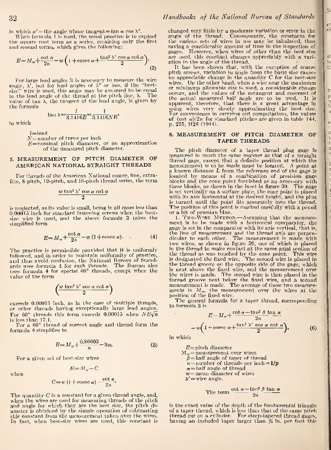
32
in which a' = the angle whose tangent=tan a cos X'. When formula 1 is used, the usual practice is to expand
the square root term as a series, retaining only the first and second termij, which gives the following:
„ , cot a , , tan^ X'cos a cot a\ ^f l + cosecaH-^- )'
(3)
For large lead angles it is necessary to measure the wire angle, X', but for lead angles of 5° or less, if the “best- size” wire is used, this angle may be assumed to be equal to the lead angle of the thread at the pitch line, X. The value of tan X, the tangent of the lead angle, is given by the formula
, I .. I tan A 3 1416B 3.1416iV£j’
in which
Handbooks of the National Bureau of Standards
changed very little by a moderate variation or error in the | angle of the thread. Consequently, the constants for \ the various sets of vires in use may be tabulated, thus ' saving a considerable amount of time in the inspection of gages. However, tvhen vires of other than the best size are used, this constant changes appreciably with a vari¬ ation in the angle of the thread. '
It has been shovm that, with the exception of coarse ■ pitch screws, variation in angle from the basic size causes no appreciable change in the quantity C for the best-size vires. On the other hand, when a vire near the maximum or minimum allov'able size is used, a considerable change occurs, and the values of the cotangent and cosecant of the actual measured half angle are to be used. It is apparent, therefore, that there is a great advantage in using wires very closely approximating the best size. For convenience in carrying out computations, the values of (cot a)l2n for standard pitches are given in table 144, p. 225, H28 (1944).
Z=lead A^ = number of turns per inch i?=nominal pitch diameter, or an approximation
of the measured pitch diameter.
5. MEASUREMENT OF PITCH DIAMETER OF
AMERICAN NATIONAL STRAIGHT THREADS
For threads of the American National coarse, fine, extra- fine, 8-pitch, 12-pitch, and 16-pitch thread series, the term
w tan^ X' cos a cot a 2
is neglected, as its value is small, being in all cases less than 0.00015 inch for standard fastening screws when the best- size wire is used, and the above formula 3 takes the simplified form
E=M„+-^-'z«(l+coseca). (4)
The practice is permissible provided that it is uniformly followed, and in order to maintain uniformity of practice, and thus avoid confusion, the National Bureau of Stand¬ ards uses formiila 4 for such threads. The Bureau also uses formula 4 for special 60° threads, except when the value of the term
(w tan^ X' cos a cot a\ 2 J
exceeds 0.00015 inch, as in the case of multiple threads, or other threads having exceptionally large lead angles. For 60° threads this term exceeds 0.00015 when NE-fn is less than 17.1.
For a 60° thread of correct angle and thread form the formula 4 simplifies to
For a given set of best-size wires
v'hen E=M^~C
C=w{\-\- cosec a) — cot a
2n
(5)
The quantity C is a constant for a given thread angle, and, when the wires are used for measuring threads of the pitch and angle for which they are the best size, the pitch di¬ ameter is obtained by the simple operation of subtracting this constant from tlie measurement taken over the wires. In fact, when best-size wires are used, this constant is
6. MEASUREMENT OF PITCH DIAMETER OF
TAPER THREADS
The pitch diameter of a taper thread plug gage is measured in much the same manner as that of a straight thread gage, except that a definite position at which the measurement is to be made must be located. A point at a known distance L from the reference end of the gage is located by means of a combination of precision gage blocks and the cone point furnished as an accessory vdth these blocks, as shown in the in.set in figure 39. The gage is set vertically on a surface plate, the cone point is placed with its axis horizontal at the desired height, and the plug is turned until the point fits accurately into the thread. The position of this point is marked carefully with a pencil or a bit of Prussian blue.
1. Two-Wire Method.—Assuming that the measure¬ ment is to be made with a horizontal comparator, the gage is set in the comparator with its axis vertical, that is, the line of measurement and the thread axis are perpen¬ dicular to each other. The measurement is made with tvm wires, as shown in figure 39, one of which is placed in the thread to make contact at the same axial section of the thread as was touched by the cone point. This wire is designated the fixed wire. The second wire is placed in the thread groove on the opposite side of the gage, which is next above the fixed vdre, and the measurement over the wires is made. The second vdre is then placed in the thread groove next below the fixed wire, and a second measurement is made. The average of these two measure¬ ments is M-u,, the measurement over the wires at the position of the fixed wire.
The general formula for a taper thread, corresponding to formula 3 is
E^My,+
+ cosec ad-
cot a —tan^ 0 tan a 2n
tan2 X' cos a cot a ). (6)
in which
/?= pitch diameter M„ = measurement over ivires
/3 = half angle of taper of thread n = number of threads per inch = 1/p a = half angle of thread w = mean diameter of wires X' = wire angle.
. cot a —tan^ jS tan a Ihe term -^-
is the exact value of the depth of the fundamental triangle of a taper thread, which is less than that of the same pitch thread cut on a cylinder. For steep-tapered thread gages, having an included taper larger than % in. per foot this

Screw-Thread Standards 33
more accurate term should be applied. For such a thread, which has a small lead angle, formula 6 take the form
„ „, , cot q; —tan^ ^ tan a ,, , , E=My;-]----u;(l+coseca) (7)
Otherwise, as for American National taper pipe threads having an included taper of Yi in. per foot, the simplified formula 5
E=M„+ 0.86603
n — Zw
the pitch diameter £?o at the small end of the gage. Eq is then determined by applying formulas 8 or 9.
3. Fouh-Wire Method.—A four-wire method of measurement which yields measurements of the pitch diameter, E^, at the small end of the gage, and the half¬ angle of taper, j3, is also sometimes used. This method is illustrated in figure 39A, and requires four thread wires of equal diameter, a pair of gage blocks of equal thickness, and two pairs of rolls of different diameters, the rolls of each pair being equal in diameter. Two measurements. Ml and M2, are made over the rolls and formulas are applied as follows:
for 60° threads may be used. This simplified formula gives a value of E that is 0.00005 inch larger than that given by the above general formula 6 for the 2}4"-8 American National taper pipe thread, the worst case in this thread series.
The pitch diameter at any other point along the thread, as at the gaging notch, is obtained by multiplying the dis¬ tance parallel to the axis of the thread, between this point and the point at which the measurement was taken, by the taper per inch, then adding the product to or subtracting it from the measured pitch diameter according to the direction in which the second point is located with respect to the first.
2. Three Wire Method.—Depending on the measuring facilities available or other circumstances, it is sometimes more convenient to use three wires. In such cases meas¬ urement is made in the usual manner, but care must be taken that the measuring contacts touch all three wires, since the line of measurement is not perpendicular to the axis of the screw when there is proper contact. (See fig. 38.) On account of this inclination, the measured distance between the axes of the wires must be multiplied by the secant of the half angle of the taper of the thread. The formula for the pitch diameter of any taper thread plug gage, the threads of which are symmetrical with respect to a line perpendicular to the axis, then has the form cor¬ responding to formula 4:
cot <x E=(My, — w) sec -w cosec a, (8)
in which /3=half-angle of taper of thread. Thus the pitch diameter of an American National standard pipe-thread gage having correct angle (60°) and taper (% inch per foot) is then given by the formula
£:=1.000491M„-W))+0.86603 p-2w. (9)
An adaption of the three-wire method is frequently used to reduce the time required when the pitch diameter of a number of gages of the same size is to be measured. Only light gages, up to about 2 in., can be measured accurately by this method. The gage is supported on two wires placed several threads apart, which are in turn supported on a taper thread testing fixture. The third wire is placed in the threads at the top of the gage and measurement is made from the top of this wire to the bottom of the fixture with a vertical comparator having a flat anvil, using a gage block combination as the standard. The fixture consists of block, the upper surface of which is at an angle to the base plane equal to the nominal angle of taper of the thread 2p. Thus the element of the cone at the top of the thread gage is made parallel to the base of the instrument. The direction of measurement is not perpendicular to the axis of the gage but at an angle, from perpendicularity. A stop is provided at the thick end of the block with respect to which the gage is positioned on the fixture. As the plane of the end of the gage may not be perpendicular to the axis, a roll approximately equal to the diameter of the gage should be inserted between the stop and the gage to assure contact at the axis of the gage. For a given fixture and roll, a constant is computed which, when sub¬ tracted from the measured distance from the top of the upper wire to the base plane, gives M corresponding to
cot 90 — 8_M2 — M\ + — (I2
M„=M2 —+cot 90°-
)-2ff sec 0,
(10)
(11)
in which
M2 = measurement over larger rolls Afi = measurement over smaller rolls
^2 = diameter of larger rolls di = diameter of smaller rolls j3 = actual half-angle of taper of thread g = thickness of each gage block.
To determine Eo, the pitch diameter at the small end of the gage, M„, as determined from formula 11, is sub¬ stituted in formulas 6 or 7.
The errors of measurement by this method may be slightly but not significantly larger than by the other methods described, on account of elastic deformations of the rolls and gage blocks under the measuring load, and differing conditions of loading of the thread wires.
Figure 39A. Measurement of -pitch diameter of, taper thread gage by the four-wire method.
7. MEASUREMENT OF PITCH DIAMETER OF
THREAD RING GAGES
The application of direct methods of measurement to determine the pitch diameter of thread ring gages presents serious difficulties, particularly in securing proper contact load when a high degree of precision is required. The usual practice is to fit the ring gage to a threaded .setting plug. When the thread ring gage is of correct lead, angle, and thread form, within close limits, this method is satis-

34
factory and represents standard American practice. It is the only method available for small sizes of threads. For the larger sizes, various more or less satisfactory methods have been devised, but none of these have found wide application.
8. WIRE METHODS OF MEASUREMENT OF ACME
THREAD PLUG GAGES
For Acme (29°) threads, the three-wire method of measurement is used. Because the angle of the thread is small, and its cotangent large, it is always necessary to take the lead angle into account in deriving pitch diameter. The general formula, 2, given again here, has been found to be the most convenient to apply,
£l=M,,-b'’'J^"-«;(l + cosec a'), (2)
in which
a' = tan“' (tan a cos X') X' = measured wire angle.
IIandbooks of the National Bureau of Standards
For a half-angle of thread of 14° 30', formula 2 takes the form
—w(l-|-cosec a') (12)
The diameter, w, of the wires used should be as close to the size which will contact the flanks of the thread at the pitch line as practicable, to avoid errors caused by deviation of the thread angle from nominal. The following formula, which takes into account the lead angle, yields a size of wire which touches the flanks of the thread close to the pitch line:
V V W(, = 2-sec “ —2 tan~'(tan a cos X). (13)
If best size wires are used, and the lead angle, X, does not exceed 5°, it may be assumed that a’' = 14°30'. The be.st wire sizes for the standard Acme thread series, resulting from this formula, are given in col. 4, table 147. The quantities, 1.933357/« are given in col. 5, table 147, H28 (1944).
Table 147A. (l-(-cosec a') for a=14°30' and wire angles from 0° to 28°
Wire i-h Differ- M'ire 1-t- Differ- AT'ire 1 “h Differ- angle cosec a! ence angle cosec a ence an gle COSGC Oi ence
deq. min. deq. min. deq. min. 0 0 4. 9939 10 0 5. 0517
20 20 20 21 21 21 22
20 0 5. 2340 43 43 43 44 44 45 45 46 40 47 47
.30 41 1 1
10 37 10 5. 2389 40 42 20 57 20 5. 2432 SO 43 30 77 30 5. 2475
1 0 45 40 98 40 .5. 2519 10 47 50 5.0619 50 ,5. 256.3 20 49
3 3 3
11 0 40 21 0 5. 2008 30 52 TO 62 10 5, 2653 40 55 20 84
23 23 23 23 24 24 25 25 25 26 26 26 27 27 27 28 28 29 29 29 30 30 .31 31 31 31 32 .3.3 .3.3 33 33 34
20 5. 2699 50 58 30 5. 0707 30 5. 2745
2 0 02 40 30 40 5. 2792 10 06 50 53 50 5. 2839 20 70
5 5
12 0 70 22 0 5, 2886 48 48
■ 49 49 50 50 51 51 52 52 53 53 53 54 55 55 56 56 56 57 58 58 59 59 60 00 01 01 62 62
, 03 64 64 65 65 66
30 75 10 5, 0800 10 5. 2934 40 80 20 5. 0824 20 5. 2082 so 8.5 30 5, OH 4 9 .30 . 5.3031
3 0 90 0
40 5. nS74 40 5. 3080 10 90 50 5,0899 50 5. .31.30 20 5. 0003
6 13 0 5. 0925 23 0 5. 31.80
30 9 10 5. 0951 10 5.3231 40 16 20 5. 0977 20 5. 3282 50 23 30 5. 1004 30 5. 3334
4 0 31 40 5.1031 40 5. 3380 10 39 50 5.10,58 50 5. 3439 20 47 14 0 5.1080 24 0 5. 3492 30 55
9 9
10 .5.1114 10 5. 3545 40 04 20 5. 11.13 20 5. 3599 so 73 30 5. 1172 30 5. 3654
5 0 82 10 10 10 11
11 11 12 12 12
40 5. 1201 40 6. 3709 10 92 50 5. 1231 50 5. 3765 20 5. 0102 15 0 5. 1201 25 0 5.3821 30 12 10 5. 1292 10 5.3877 40 23 20 5. 1323 20 5. 3934 50 34 30 5.13,54 30 5. 3992
6 0 10
45 57
40 50
5. 1.385 .5. 1417
40 50
5. 4050 5. 4109
20 09 16 0 5. 1450 26 0 5. 4168 30 81 10 5, 1483 10 5. 4228 40 94 20 5. 1516 20 5.4288 50 5. 0207
13 14 14 14 15 15 15 16 16 16 17 17 17 18 18 18 19 19 19
30 5.1549 30 5. 4349 7 0 20 40 5.1583 40 5. 4410
10 34 50 .5.1617 35 .35 .36 36 36 37 37 37 38 .38 39 .39 40 40 40 41 41 42 42
50 5. 4472 20 48 17 0 5. 1652 27 0 5. 4534 30 62 10 5. 1087 10 5. 4597 40 77 20 5. 1723 20 5. 4661 50 92 30 5. 1759 30 5. 4725
8 0 5. 0307 40 5.1795 40 5. 4790 10 23 50 5.1832 - 50 5. 4855 20 39 18 0 5. 1869 28 0 5. 4921 30 55 10 5. 1906 40 72 20 5. 1944 50 89 30 5. 1982
9 0 5. 0406 40 5. 2021 10 24 50 5. 2060 20 42 19 0 5.2100 30 60 10 5. 2140 40 79 20 5. 2180 50 98 30 5. 2221
40 5. 2262 50 5. 2304
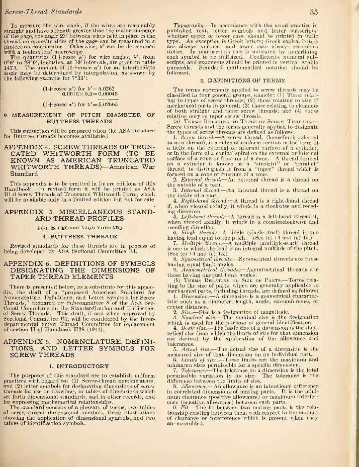
Screw-Thread Standards 35
To measure the wire angle, if the wires are reasonably straight and have a length greater than the major diameter of the gage, the angle 2X' between wires held in place in the thread on opposite sides of the gage can be measured in a projection comparator. Otherwise, X' can be determined with a toolmakers’ microscope.
The quantities (1 +cosec a') for wire angles, X', from 0°0' to 28°0', inclusive, at 10' intervals, are given in table 147A. The amount of (1 +cosec a') for an intermediate angle may be determined by interpolation, as shown by the following example for 7°33':
(1 +cosec ot') for X' = 5.0262 0.0015X0.3 = 0.00045
(1 + cosec a') for X' = 5.02665
9. MEASUREMENT OF PITCH DIAMETER OF
BUTTRESS THREADS
This subsection will be prepared when the ASA standard for Buttress threads becomes available.!
APPENDIX 4. SCREW THREADS OF TRUN¬ CATED WHITWORTH FORM (TO BE KNOWN AS AMERICAN TRUNCATED WHITWORTH THREADS)—American War Standard
This appendix is to be omitted in future editions of this Handbook. In revised form it will be printed as ASA B1.6 Screw Threads of Truncated Whitworth Form, which will be available only in a limited edition but not for sale
APPENDIX 5. MISCELLANEOUS STAND¬ ARD THREAD PROFILES
2 (a). 29 DEGREE STUB THREADS
4. BUTTRESS THREADS
Revised standards for these threads are in process of being developed by ASA Sectional Committee Bl.
APPENDIX 6. DEFINITIONS OF SYMBOLS DESIGNATING THE DIMENSIONS OF TAPER THREAD ELEMENTS
There is presented below, as a substitute for this appen¬ dix, the draft of a “proposed American Standard for Nomenclature, Definitions, and Letter Symbols for Screw Threads,” prepared by Subcommittee 8 of the ASA Sec¬ tional Committee on the Standardization and Unification of Screw Threads. This draft, if and when approved by Sectional Committee Bl, will be considered by the Inter¬ departmental Screw Thread Committee for replacement of section II of Handbook H28 (1944).
APPENDIX 6. NOMENCLATURE, DEFINI¬ TIONS, AND LETTER SYMBOLS FOR SCREW THREADS
1. INTRODUCTORY
The purpo.ses of this standard are to establish uniform practices with regard to: (1) Screw-thread nomenclature, and (2) letter symbols for designating dimensions of screw threads for use on drawings, in tables of dimensions which set forth dimensional standards, and in other records, and for expressing mathematical relationships.
The standard consists of a glossary of terms, two tables of screw-thread dimensional symbols, three illustrations showing the application of dimensional symbols, and two tables of identification symbols.
Typography.—In accordance with the usual practice in published text, letter symbols and letter subscripts, whether upper or lower case, should be printed in italic type. An exception is Greek letters; Greek capital letters are always vertical, and lower case always resembles italics. In manuscripts this is indicated by underlining each symbol to be italicized. Coefficients, numeral sub¬ scripts, and exponents should be printed in vertical Arabic numerals. Standard mathematical notation should be followed.
2. DEFINITIONS OF TERMS
The terms commonly applied to screw threads may be classified in four general groups, namely: (1) Those relat¬ ing to types of screw threads; (2) those relating to size of mechanical parts in general; (3) those relating to elements of both straight and taper screw threads; and (4) those relating only to taper screw threads.
(a) Terms Rel.vting to Types op Screw Threads.—
Screw threads and the terms generally applied to designate the types of screw threads are defined as follows:
1. Screw thread.—A screw thread, (henceforth referred to as a thread), is a ridge of uniform section in the form of a helix on the external or internal surface of a cylinder, or in the form of a conical spiral on the external or internal surface of a cone or frustum of a cone. A thread formed on a cylinder is known as a “straight” or “parallel” thread, to distinguish it from a “taper” thread which is formed on a cone or frustum of a cone.
2. External thread.—An external thread is a thread on the outside of a part.
3. Internal thread.—An internal thread is a thread on the inside of a part.
4. Right-hand thread.—A. thread is a right-hand thread if, when viewed axially, it winds in a clockwise and reced¬ ing direction
5. Left-hand thread.—A thread is a left-hand thread if, when viewed axially, it winds in a counterclockwise and receding direction.
6. Single thread.-—A single (single-start) thread is one having lead equal to the pitch. (See (c) 14 and (c) 15.)
7. Multiple thread.—A multiple (multii)le-start) thread is one in which the lead is an integral multiple of the pitch. (See (c) 14 and (c) 15.)
8. Symmetrical threads.—Symmetrical threads are those having equal flank angles.
9. Asymmetrical threads.—Asymmetrical threads are those having unequal flank angles.
ih) Terms Relating to Size of Parts.-—Terms rela¬ ting to the size of parts, which are generally applicable to mechanical parts, including threads, are defined as follows:
1. Dimension.—A dimension is a geometrical character¬ istic such as a diameter, length, angle, circumference, or center distance.
2. Size.—Size is a designation of magnitude. 3. Nominal size.—The nominal size is the designation
which is used for the purpose of general identification. 4. Basic size.—The basic size of a dimension is the theo¬
retical size from which the limits of size for that dimension are derived by the application of the allowance and tolerances.
5. Actual size.—The actual size of a dimension is the measured size of that dimension on an individual part.
6. Limits of size.—These limits are the maximum and minimum sizes permissible for a specific dimension.
7. Tolerance.—The tolerance on a dimension is the total permissible variation in its size. The tolerance is the difference between the limits of size.
8. Allowance.—An allowance is an intentional difference in correlated dimensions of mating parts. It is the mini¬ mum clearance (positive allowance) or maximum interfer¬ ence (negative allowance) between such parts.
9. Fit.—The fit between two mating parts is the rela¬ tionship existing between them with respect to the amount of clearance or interference which is present when they are assembled.

36
(c) Teems Relatino to Elements of Screw
Threads.—Terms relating to dimensions and other ele¬ ments of both straight and taper threads are defined as follows;
1. Axia.—The axis of a thread is the axis of the cylinder, cone, or frustum of a cone on which the thread is formed.
2. Form.—The form of thread is its profile in an axial plane for a length of one pitch.
3. Basic form.—The basic form of thread is that form in which the size of each dimension is basic.
4. Flank or side.—The flank or side of a thread is either surface connecting the crest with the root, the intersection of which, with an axial plane, is a straight line.
5. Crest.—The crest is that surface of the thread which joins the sides of the thread and is farthest from the cylinder, cone, or frustum of a cone from which the thread projects.
6. Root.—The root is that surface of the thread which joins the sides of adjacent threads and is identical with or immediately adjacent to the cylinder, cone, or frustum of a cone from which the thread projects.
7. Base.—The base of a thread is that section of the thread which coincides with the cylinder, cone, or frustum of a cone from which the thread projects.
8. Sharp crest.—The sharp crest is the intersection of the flanks or sides of a thread when extended, if necessary, beyond the crest.
9. Sharp root.— The sharp root is the intersection of the flanks or sides of adjacent threads when extended, if necessary, beyond t he root.
10. Leading flank.—The leading flank or side of a thread is the one which, when the thread is about to be assembled with a mating thread, faces the mating thread.
11. Following flank.—The following flank or side of a thread is the one which is opposite to the leading flank or side.
12. Crest truncation.—The crest truncation of a thread is the distance, measured perpendicular to the axis, between the sharp crest and the cylinder or cone which bounds the crest.
13. Root truncation.—The root truncation of a thread is the distance, measured perpendicular to the axis, between the sharp root and the cylinder or cone which bounds the root.
14. Pitch.—The pitch of a thread is the distance, meas¬ ured parallel to its axis, between corresponding points on adjacent threads in the same axial plane.
15. Lead.—The lead is the distance a thread moves axially, with respect to a fixed mating thread, in one complete rotation.
16. Included angle.—The included angle of a thread is the angle between the flanks or sides of the thread meas¬ ured in an axial plane.
17. Flank angle.—The flank angles are the angles be¬ tween the Individual sides and the jierpendicular to the axis of the thread, measured in an axial plane. A flank angle of a symmetrical thread is commonly termed the “half-angle of thread.”
18. Lead angle.—On a straight thread the lead angle is the angle made by the helix of the thread at the pitch line with a plane perpendicular to the axis. On a taper thread, the lead angle at a given axial [)0.sition is the angle made by the conical spiral of the thread at the pitch line with the plane periiendicular to the axis at that position.
19. Thickness.—The thickness of thread is the distance between the flanks or sides of the thread measured at a specified diameter and jjarallel to the axis.
20. Number of threads.—The number of threads denotes the number per unit of length (per inch), and is the recip¬ rocal of the pitch. (See (c)14.)
21. Number of turns.—The number of turns per unit of length (per inch) is the number of rotations reepured to advance a screw axially that unit of length, with respect to a fixed mating thread. It is the reciprocal of the lead. (See (c) 15.)
22. Height of fundamental triangle.—The height of the
Handbooks of the National Bureau of Standards '
fundamental triangle of a thread, or the height of a sharp- V thread, is the distance measured perpendicular to the axis between the sharp major and minor cylinders or cones, respectively. (See (d) 3 and (d) 5.)
23. Height or depth.—The height or depth of thread is the distance between the major and minor cylinders or cones, respectively. (See (d) 2 and (d) 4.)
24. Addendum.—The addendum of an external thread is the distance, measured perpendicular to the axis, be¬ tween the major and pitch cylinders or cones, respectively. The addendum of an internal thread is the distance, measured perpendicular to the axis, between the minor and pitch cylinders or cones, respectively.
25. Dedendum.—The dedendum of an external thread is the distance, measured perpendicular to the axi's, be¬ tween the pitch and minor cylinders or cones, respectively. The dedendum of an internal thread is the distance, mea¬ sured perpendicular to the axis, between the major and pitch cylinders or cones, respectively.
26. Depth of thread engagement.—The depth of thread engagement between two mating threads is the distance, measured perpendicular to the axis, by which their thread forms overlap each other. One-hundred-percent depth of thread engagement is the distance, measured perpendicular to the axis, between the basic major and basic minor diameters.
27. Length of thread engagement.—The length of thread engagement of two mating threads is the distance between the extreme points of contact on the pitch cylinders or cones, measured parallel to the axis.
28. Major diameter.—On a straight thread, the major diameter is the diameter of the imaginary coaxial cylinder which bounds the crest of an external thread or the root of an internal thread.
On a taper thread, the major diameter, at a given posi¬ tion on the thread axis, is the diameter of the major cone a,t that position. (See (d) 2.)
29. Minor diameter.—On a straight thread, the minor diameter is the diameter of the imaginary coaxial cylinder which bounds the root of an external thread or the crest of an internal thread.
On a taper thread, the minor diameter, at a given posi¬ tion on the thread axis, is the diameter of the minor cone at that position. (See (d) 4.)
30. Pitch diameter.—On a straight thread, the pitch diameter is the diameter of the imaginary coaxial cylinder, the surface of which would pass through the threads at such points as to make the width of the threads equal to the width of the spaces cut by the surface of the cylinder.
On a taper thread, the pitch diameter at a given position on the thread axis is the diameter of the pitch cone at that position. (See (d) 1.)
In British nomenclature this dimension is called the “effective diameter.”
31. Pitch line.—The pitch line is an element of the imaginary cylinder or cone specified in the definition of pitch diameter.
32. ^^anish cone.—The vanish cone is an imaginary cone, the surface of which would pass through the roots of in¬ complete 1 breads formed by the lead or chamfer of the threading tool. These threads are referred to as “vanish threads” or “washout threads.”
33. Vanish point.—The vanish point of an external thread is the intersection of an element of the vanish cone with an element of the cylinder of the largest major diameter of the thread.
34. Crest clearance.—The crest clearance in a thread as¬ sembly is the distance between the crest of a thread and the root of its mating thread.
35. Higbee cut.—“Higbee cut” designates the removal of the partial thread at the entering end of thread, creating a blunt start. This is a feature of threaded parts which are repeatedly assembled by hand, such as hose couplings and thread jilug gages, to jirevent cutting of the hands and crossing of threads. (See fig. 55B.)
36. Stress area.—The stress area is the assumed area of

Screw-Thread Standards 37
an externally threaded part which is used for the purpose of computing the tensile strength.
(d) Terms Relatino Only to Taper Screw Threads.—
Terms relating only to taper threads are defined as follows: 1. Pitch cone.—The pitch cone is an imaginary cone,
the surface of which would pass through the thread at such points as to make the widths between the sides of the thread equal to the spaces between the sides of adjacent threads.
2. Major cone.—The major cone is an imaginary cone having an apex angle equal to that of the pitch cone, the surface of which bounds the crest of an external thread or the root of an internal thread.
3. Sharp major cone.—The sharp major cone is an im¬ aginary cone having an apex angle equal to that of the pitch cone, the surface of which would pass through the sharp crest of an external thread or the sharp root of an internal thread.
4. Minor cone.—The minor cone is an imaginary cone having an apex angle equal to that of the pitch cone, the surface of which bounds the root of an external thread or the crest of an internal thread.
5. Sharp minor cone.—The sharp minor cone is an im¬ aginary cone having an apex angle equal to that of the pitch cone, the surface of which would pass through the sharp root of an external thread or the sharp crest of an internal thread.
6. Standoff.—The standoff is the axial distance between specified reference points on external and internal taper threaded members or gages, when assembled with a specified torque or under other specified conditions.
3. LETTER SYMBOLS AND ABBREVIATIONS
Symbols associated with screw threads are of two kinds: (1) Letter symbols for designating dimensions of screw threads and threaded products; and (2) abbreviations used as identification symbols for designating various standard thread forms and thread series.
(a) Dimensional Symbols.—Standard letter symbols to de.signate the dimensions of screw threads are given in tables 162A and 162B. General symbols are given in table 162A and pipe thread symbols, in 162B. The application of general symbols are illustrated in figures 55A and 55B and pipe thread symbols in figure 55C.
(b) Identification Symbols.—Identification symbols are capital letter abbreviations of names used to designate various forms of thread and thread series, and commonly consist of combinations of such abbreviations. There are assembled in table 162C the names and abbreviations which are now in use, together with references to standards in which they occur. The names of various standard threads, and their corresponding identification symbols, consisting of certain combinations of abbreviations, together with references, are compiled in table 162D.
The method of designating a screw thread by means of symbols is by the use of the initial letters of the thread series, preceded by the diameter in inches (or the screw number) and number of threads per inch, all in Arabic characters, and followed by the classification of fit in Arabic numerals. For example, a threaded part of the American National coarse thread series, inch in diameter, 13 threads per inch, class 3 fit, is designated 54"-13NC-3. The identification symbol applicable to each thread series is stated in the section where such series is presented. If the thread is left hand, the syrnbol “LH” shall follow the class of fit. No symbol is used to distinguish right hand threads. The number of threads per inch shall be in¬ dicated in all cases, irrespective of whether it is the standard number of threads for that particular size of threaded part, or special. Tools and gages for standard thread diameters and pitches shall bear standard identi¬ fication symbols, and special marking of such items shall be avoided.
For screw threads of American National form but of
special diameters, pitches, and lengths of engagement, the symbol “NS” shall be used. It is occasionally desirable to modify a standard thread by the inclusion of some non¬ standard feature. Thus, it might be necessary to limit the maximum major diameter of a )4"-13NC-3 screw to 0.4800 inch in order to provide clearance for a shoulder. The word “modified” should be added to the designation with an asterisk (*), and the nonstandard feature or dimension of the thread should be enclosed in brackets and likewise marked with an asterisk (*).
Multiple threads shall be designated by showing both the pitch and the lead in accordance with examples given on p. 162, H28 (1944).
Table 162A. General symbols {see figs. 55A and 55B)
D
Symbols Dimensions
Major diameter.
E. K
Pitch diameter.. Minor diameter.
P- i..
N.
H. h..
Pitch___ Lead_ Number of threads per unit of
length (per inch). Number of turns per unit of
length (per inch), Height of fundamental triangle.. Height of thread__
_ hd_ hi- ft,_ a (alpha).
ai-
ai
Addendum. Dedendum. Equals 2fto of basic external
thread. Depth of thread engagement. Half-angle of symmetrical
thread. Angle between leading flank
of thread and normal to axis of thread.
Angle between following flank of thread and normal to axis of thread.
Remarks
Exception: B is used for basic major diameter when this differs from the nominal major di¬ ameter. Subscripts s or n, indicating external or internal thread, may be used if necessary.
[Subscripts s or n, indicat- I ing external or internal I thread, may be used if I necessary. Equals 1/re. Equals 1/iV.
Subscripts s or re, indicat¬ ing external or internal thread, may be used it necessary.
X (lambda). Lead angle. Tan X = J_. ttE
T Radius of rounding at crest, or radius of rounding at root.
Subscripts c or r indicating crest or root, and s or re indicating external or in¬ ternal thread may be used if necessary.
Fen.
Frn-
L-. L,..
Depth from apex of funda¬ mental triangle to adja¬ cent root or crest of thread;
(1) If rounded. (2) If flat.
Depth from apex of funda¬ mental triangle to:
(1) Flat at crest of external thread.
(2) Flat at root of external thread.
(3) Flat at crest of internal thread.
(4) Flat at root of internal thread.
Width of: (1) Flat (general). (2) Flat at crest of external
thread. (3) Flat at root of external
thread. (4) Flat at crest of internal
thread. (5) Flat at root of internal
thread. Length of bolt or screw. Length of full thread_ Subscripts s or re, indicat¬
ing external or internal thread, may be used if necessary.
L... w. _
Length of thread engagement. Diameter of measuring wires. Measurement over wires. Measurement under wires.

38
Table 162A. General symbols (see figs. 55A and 55B)— Continued
Symbols Dimensions Remarks
c _ Correction to measurement E=M„-C-c.
p ..
over wires to give pitch di¬ ameter.
Correction to measurement
C=w(\ -p cosec a) — (cot a)/2m.
E= T+P-c.
X'
under wires to give pitch di¬ ameter.
P=l/2p cot a—(coseo a— l)w.
[See NPL “Notes on Screw C- - __
Prefix symbol with b (del¬ ta).
AEa (delta Ea).
(delta Ep).
O _
Wire angle correction-
Error in any dimension -..
Pitch-diameter equivalent of errors in flank angles.
Pitch-diameter equivalent of error in pitch. ■
Allowance at pitch diameter.
Basic truncation of crest from
Gages”, August 1944, p. 23, or NBS Handbook H28 (1944), p. 228.
Examples: Error in pitch, 5p; error in half-angle, 5o:i or boti.
u_ f(l) 17= Height of segment
of B. S. Whitworth crest.
k_ basic Whitworth form.
Height of truncated Whit¬ worth thread.
1 (2) These symbols apply only to Truncated Whit-
1 worth threads.
Table 162B. Pipe-thread symbols (see fig. 55c)
Symbols Dimensions Remarks
z> Outside diameter of pipe. .. Subscript 4 is used for di¬
mensions in plane of van- d Inside diameter of pipe. .. . . ish point when these f _ Wall thickness of pipe_ differ from D, d, or t.
Z)x _ Major diameter.
respectively. Subscript x denotes plane
containing the diameter. For axial positions of planes see foot of table 162B. Subscripts s or n designating screw or nut may also be used if necessary.
For axial position of plane
Ex Pitch diameter. . Kx Minor diameter .
Lp_ Length of thread from plane of pipe end to plane contain- containing basic diam- ing basic diameter Lx, Ex, or eter, see foot of table Kx. 162B.
V _ Length of washout (vanish
/3 (beta)_ cone) threads.
Half apex angle of pitch cone of
7 (gamma) — taper thread.
Angle of chamfer at end of pipe
A...
measured from a plane nor¬ mal to the axis.
Hand tight standoff of face of
M..
coupling from plane contain¬ ing vanish point on pipe.
Length from plane of hand tight engagement to the face of coupling on internally threaded member.
Handbooks of the National Bureau of Standards
Table 162B. Pipe-thread symbols (see fig. 55c)—Con.
Symbols Dimensions Remarks
b_
T (tau)_
e (epsilon)_ J_
Li..
Q-
9--
W.
Distance of gaging step of plug gage from face of ring gage for hand tight engagement.
Length from center line of coupling, face of flange, or bottom of internal thread chamber to face of fitting.
Width of bearing face on coupling.
Angle of chamfer at bottom of recess or counterbore meas¬ ured from the axis.
Half apex angle of vanish cone_ Length from center line of
coupling, face of flange, or bottom of internal thread chamber to end of pipe, wrenched engagement.
(1) Length of straight full thread (see table 162A).
(2) Length from plane of hand- tight engagement to small end of full internal taper thread.
Diameter of recess or counter¬ bore in fitting.
Depth of recess or oounterbore in fitting.
Outside diameter of coupling or hub of fitting.
i
DEFINITJON OF PLANES DENOTED BY SUBSCRIPT X
X = 0.
X=1
X =
X=
2.
3.
1=4.
1=5.
Plane of pipe end_ ] Gage plane, or plane at mouth j
of coupling (excluding recess, ; if present). 4
Plane at which washout threads on pipe commence.
Plane in coupling reached by end of pipe in wrenched condition.
Note.^Ls is measured from plane containing pipe end in position of handtight engagement.
Plane containing vanish point of thread on pipe.
Plane at which major diam¬ eter cone of thread intersects outside diameter of pipe.
Note.—Additional special subscripts are as follows: Plano t:=6 is the plane of the pipe end for railing joints. Plane x=l is the plane of the API gage point at a specified length from the plane of vanish pohit. Plane i=8 is the plane of the large end of the “is thread ring gage” for the compressed-gas cylinder valve connection thread. Plane a'=9 is the plane of the small end of the “Li thread plug gage” for the compressed-gas cylinder neck thread.

Screio-Thread Standards 39
Table 162D.—Identification symbols *
Symbol Thread series
References
ASA Standards Handbook H28 (1944), section No.
American Standard Acme threads, centralizing_ _ . . . . , B 1.5-1945 X American Standard Acme threads, general puipose_ Bl.5-1945 x! American Standard Stub Acme thread. .. . . _ . Bl.ll American Standard buttress thread. .. _ . _ ... _
NC _ American National coarse thread series. .. . . _ .. _ Bl.1-1935 IV NF _ American National fine thread series. ___ _ _ . Bl.1-1935 IV nef _ American National extra-fine thread series . . .. IV 8N _ American National 8-pitoh thread series_ _ .. _ ..._ . .. . .. .. Bl.1-1935 IV 12N _ American Natilnal 12-pitch thread series.- .. .. _ _ . .-. _ _ Bl.1-1935.... IV 16N _ American National 16-pitch thread series.. .. _ ..... . Bl.1-1935 IV NH _ American National hose coupling and fire hose coupling threads ... . _ vii ngo_ American National gas outlet threads - - .. ... . _ . _ .. NS ---- Special threads of American National form.. ... . __ _ . V NPT _ American Standard taper pipe threads.. ... B2.1-1945 vi. NPSC B2.1-1945 VI NPTF . -- American Standard taper pipe thread (drvseal) . . B2.1-1945 VI npsf _ American Standard straight pipe thread (drvseal) ._ ...... . B2.1-1945 VI. NPSI B2.1-1945, App. E npSm American Standard straight pipe thread for mechanical joints. . B2.1-1945 VI. npsl_ American Standard straight pipe thread for locknuts and locknut pipe threads. . B2.1-1945_ VI. NPSH American Standard straight pipe thread for hose couplings and nipples. B2.1-1945 . _ VI. NPTR - - B2.1-1945 VI. BSW-T B1.6 BSF-T _ British Standard fine truncated . . .. B1.6 BSPP-T_ British Standard nine fDarallpll tinncated _ .. . . R1.6
1 Methods of designating multiple threads are shown in ASA B 1,5-1945, American War Standard for Acme Threads, and section X of Handbook H28 (1944).

40 Handbooks of the National Bureau of Standards
mmmmm Depth of thread engasement
where an allowance is provided.
Figure 55B.
COUPLING NIPPLE
Highee cut.
General screw thread symbols.

Screw-Thread Standa7'ds 41
cT e
It
c o
o £ to "^3
•S'< § S~ <b
5- o '' ■2?
C: ^
c o <o
'& 2 ^
^ «' I'i o Q.tlo
SioT '♦'
N
ti:
•«: •$3
o Si <b ^
S, 11, tio
«>. V, ' 5
r 1'' tv,
I ^ n, g
ti^ tl) ?5
§ t 5;iS
•t, .c;
tS
.y>
I S. o
.Ci.
cC
a. c .Jo $
s.
IS &
1,
ts
1^
.a cC
APPENDIX 8. ENDORSEMENTS
The following insertions and revisions are to be made on p. 271, second column of text: after line 16, insert;
“WW-C-571. Conduit; Steel, Rigid, Enameled,” amended
August 22, 1945. WW-C-581a. “Conduit; Steel, Rigid, Zinc-Coated.”
Near bottom of second column, change price of Nos. 5-A and 7-B to $1.00; change price of 5-F to 75 cents. Change No. 11-A to read; No. 11-A API Specifications for Oil Well Pumps ($1.25).

APPENDIX 9. UNIFIED SCREW THREADS
1. FOREWORD
On November 18, 1948, the Declaration of Accord with respect to the
Unification of Screw Threads shown on the opposite page was signed hy repre-
sentntives of government and industry of Canada, the United Kingdom, and
the United States. Tlie publication of the Interdepartmental Screw Thread
Committee, which was referred to in the Accord, was entitled, “Unified Screw
Threads as Recommended by the Interdepartmental Screw Tliread Committee.”'
The proposed Unified standards for thread form, for the coarse thread
series in sizes from Yi inch to 4 inches, inclusive, and for the fine thread series
in sizes from Y inch to 1% inches, inclusive, here presented, are in agreement
with those in the above mentioned publication except that they have been
modified in the following respects: (1) The allowance for class lA is 0..30(>
instead of 0.450 times the class 2A pitch diameter tolerance, and (2) the minor-
diameter tolerances of internal threads have been modified slightly to place
them on a consistent basis. These proposed standards, together with addi¬
tional standards for threads of special diameters and pitches which are not now
in final form, have heretofore not been submitted but will be submitted, in accord¬
ance with the usual procedure,/or approval of each of the Departments repre¬
sented on the Committee.
E. U. Condon, Chairman^ March 1949.
42
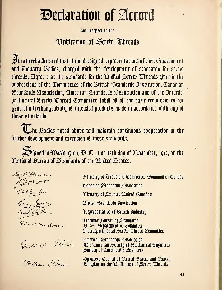
©Eclaration of accoril toith resptct to the
lanification of ^cretti 'Chrcads
ift is httcbg dtclartd that the undersigned, representatiues of their 0ouernmcnt and andustrp )Bodies, eharged toith the deuelopment of standards for screto threads, agree that the standards for the Unified hereto IChreads giuen in the puhlieations of the Committees of the British Standards 3nstitution, Canadian Standards assotiation, amtrican Standards association and of the 3nttrdt- partmental ,^trttn 'Chrtad Committee fnifill all of the basic requirements for general intcrthangcabilitg of threaded products made in accordance toith ang of these standards.
1:^1 Mt JBodics noted aboDe toill maintain continuous cooperation in the further development and extension of these standards.
Signed in fDashington, B. C., this isth dag of Jlovembcr, 19^$, at the Bational JBureau of Standards of the Bnited States.
hUfin'wis-' 'fR fl ■
a
Ministrii of ICradc and Commerce, Bominion of Canada
Canadian Standards association
ministrji of ^upplu, Bnited kingdom
^British Standards Institution
Uepresentatiue of JBritish Industrji
Bational jBureau of Standards B. 3. Bepartment of Commerce Interdepartmental hereto 'Chread Committee
american Standards association IChe american ^ocietp of fUechanical 3£npeers ^ocietn of automotive Engineers
Sponsors Council of Hnited States and Bnited Eingdom on the Bnification of hereto IChreads
43
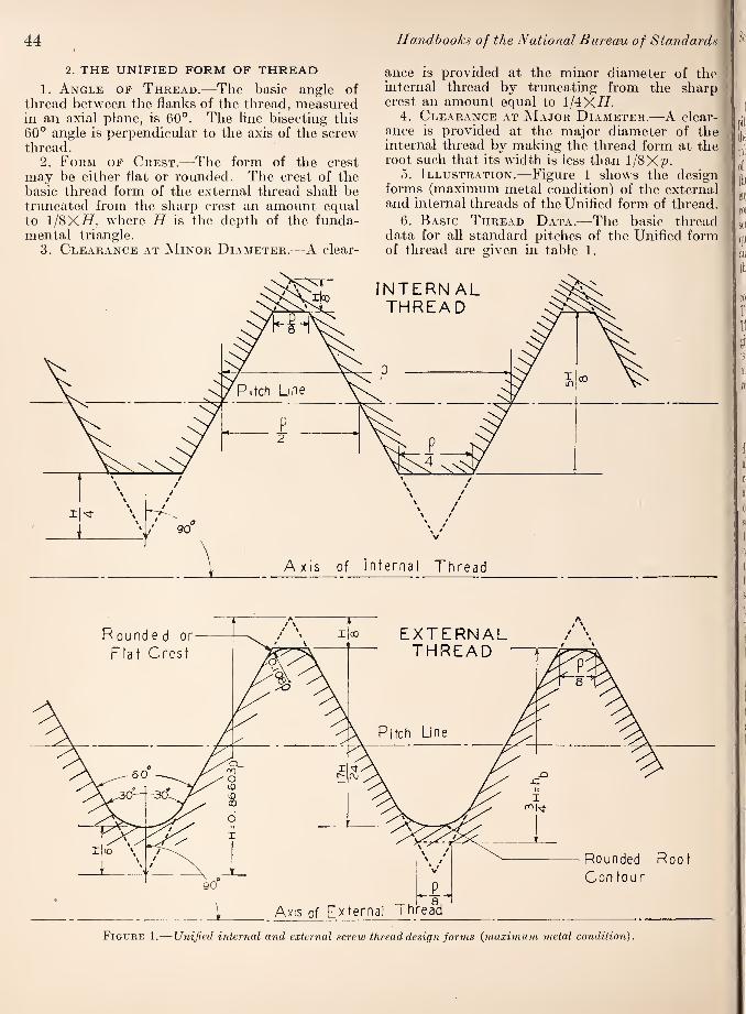
44
2. THE UNIFIED FORM OF THREAD
1. Angle of Thread.—The basic angle of thread between the flanks of the thread, measured in an axial plane, is 60°. The line bisecting this 60° angle is perpendicular to the axis of the screw thread.
2. Form of Crest.—The form of the crest may be either flat or rounded. The crest of the basic thread form of the external thread shall be truncated from the sharp crest an amount ecpial to l/8XiT, where H is the depth of the funda¬ mental triangle.
3. Clearance at .Minor Diameter.—A clear-
Handhooks of the National Bureau of Standards
ance is provided at the minor diameter of the internal thread by truncating from the sharp crest an amount equal to l/4Xi7.
4. Clearance at Major Diameter.—A clear¬ ance is provided at the major diameter of the internal thread by making the thread form at the root such that its width is less than 1/8Xp.
5. Illustration.—Figure 1 shows the design forms (maximum metal condition) of the external and internal threads of the Unified form of thread ^
6. Basic Thread Dat.^.—The basic thread ; data for all standard pitches of the Unified form of thread are given in table 1. ■
Figure 1.—Unified internal and external screw thread design forms {maximum metal condition).

Screw-Thread Standards 45
3. THREAD SERIES AND SUGGESTED
APPLICATIONS
1. Coarse Thread Series.—The diameter- pitch combinations and the basic dimensions of the Unified coarse thread series are given in table 2. The limits of size for the three classes of fit are given in tables 4 and 6. The coarse thread series is recommended for general use in engineering work, in machine construction where conditions are favorable to the use of bolts, screws, and other threaded components where quick and easy assembly of the parts is desired, and for all work where conditions do not require the use of fine-pitch threads.
2. Fine Thread Series.—The diameter-pitch combinations and the basic dimensions of the Unified fine-thread series are given in table 3. The limits of size for the three classes of fit are given in tables 5 and 7. The fine thread series is recommended for general use in automotive and aircraft work, and where special conditions require a fine thread.
4. CLASSIFICATION AND TOLERANCES
There are established for general use three distinct classes of screw-thread tolerances and allowances as specified in the following brief outline. These three classes, together with the accompanying specifications, are for the purpose of insuring the interchangeable manufacture of screw-thread parts. This standard includes classes lA, 2A, and 3A, applied to external threads only, and classes IB, 2B, and 3B applied to internal threads only. The requirements for a screw- thread fit for specific applications can be met by specifying the proper combination of classes for the components. For example, an external thread made to class 2A limits can be used with tapped holes made to classes IB, 2B, or 3B limits for specific applications.
It is not the purpose of this standard to limit applications of the various standard classes. However, classes 2A and 2B were designed for the normal production of screws, bolts, and nuts, and so far as practicable such production should be limited to these classes. They are also suitable for a wide variety of other applications.
(a) GENERAL
The following general specifications apply to all classes specified for applications of the Unified form of thread.
1. Uniform Minimum Internal Thread.—
The minimum major, pitch, and minor diameters of the internal thread are respectively the same for classes IB, 2B, and 3B.
2. Direction and Scope of Tolerances.—
(a) The tolerance on the internal thread is plus, and is applied from the basic size to above basic size.
(6) The tolerance on the external thread is minus, and is applied from the maximum (or de¬ sign) size to below the maximum size.
(c) The tolerances specified represent the ex¬ treme variations permitted on the product.
3. Basic Formula for Allowances and Tol¬
erances.—The basic formula, from which allow¬ ances on all diameters and tolerances on pitch diameter are derived, is:
Tolerance (or allowance) = ^7(0.0015-^D+0.0015
VI^+0.015 VPL
where
(7= a factor which differs for each allowance or tolerance for each class
basic major diameter Ze=length of engagement
/> = pitch.
This formula is based on the accuracy of present day threading practice, and is applicable to all reasonable combinations of diameter, pitch, and length of engagement. Numerical values of the increments in the formula for standard diameters, pitches, and lengths of engagement are given in table 8.
4. Allowances.—Allowances are applied only to external threads. The values of the factor C (par. 3 above) for allowances are as follows:
Class Factor C
lA 0. 300 2 A . 300 3A . 000
5. Pitch Diameter Tolerances.— (a) Values of factor C.—The values of the factor C (par. 3 above) for pitch diameter tolerances are as follows:
Class Factor C
lA 1. 500 IB 1. 950 2A 1. 000 2B 1. 300 3A . 750 3B . 975
It will be noted that the factor C is 30 percent greater for internal than for external threads of a given class number on account of the relative difficulties of manufacture.
(6) Tolerances cumulative.—The tolerances on pitch diameter are cumulative, that is, they in¬ clude the variations of lead and angle. Therefore,

Max
imun
n M
ajor
Dia
met
er
of.
Inte
rnal
Thre
ad
Min
imum
Majo
r D
iam
eter
of
Inte
rnal
Th
read
Max
imum
Maj
or
Dia
met
er
of
Exte
rnal T
hre
ad
46 Handbooks of the National Bureau of Standards

Screio-Thread Standards 47

48
the full tolerance is not available for pitch di¬ ameter unless the lead and angle of the thread are perfect.
(c) Length of engagement.—The tolerances on pitch diameter for the coarse and fine thread series are based on a length of engagement equal to the basic major diameter.
6. Major Diameter Tolerances.— (a) Ex¬ ternal threads.—The tolerance on major diameter for class lA is equal to 0.09 and for classes 2A
and 3A is equal to 0.06 ^p^. Tolerances equal to
0.09 ^jp"^ are provided for class 2A products of un¬ finished, hot-rolled material.
(6) Internal threads.—No tolerance is specified, as the maximum major diameter is established by the crest of an unworn tool. See footnote 2, tables 5 and 7.
7. Minor Diameter Tolerances.'—(a) Exter¬ nal threads.-—No tolerance is specified, as the minimum minor diameter is established by the crest of an unworn tool. See footnote 2, tables 4 and 6.
(6) Internal threads.-—The tolerance on minor diameter for a given size and pitch of thread is the same for all classes.
For all Unified coarse and fine series threads 1 inch and larger in size, the tolerance is equal to 0.120p. For sizes less than 1 inch in size, most tolerances are larger than 0.120p to minimize tap¬ ping difficulties (in accordance with formulas to be published in connection with special diameter- pitch combinations).
(b) SCREW-THREAD CLASSES
1. Classes 1A and iB.-—ia) Definition.—The combination of classes lA and IB is intended to cover the manufacture of threaded parts where quick and easy assembly is necessary, and where an allowance is required to permit ready assembly, even when the threads are slightly bruised or dirty.
(6) Allowances and tolerances.—Allowances and
Handbooks of the National Bureau of Standards
tolerances for the respective thread series are spec¬ ified in tables 4, 5, 6, and 7 and their application is shown in figure 2.
2. Classes 2A and 2B.'—(a) Definition.-—Class 2A for external threads and 2B for internal threads are standards designed for screws, bolts, and nuts. They are also suitable for a wide variety of other applications. A moderate allowance is provided which minimizes galling and seizure encountered in assembly and use; it also accommodates plat¬ ings, finishes, or coatings. The maximum dimen¬ sions of threads which are electroplated or have coatings of similar thickness are increased by the amount of the allowance.
{h) Allowances and tolerances.-—Allowances and tolerances for the respective thread series are specified in tables 4, 5, 6, and 7, and their appli¬ cation is shown in figure 2.
3. Classes 3A and 3B.'—(a) Definition.—Class 3A for external threads and class 3B for internal threads p/ovides a class of fit for such applications where closeness of fit and accuracy of lead and angle of thread are important. They are obtain¬ able consistently only by the use of high quality production equipment supported by a very effi¬ cient system of gaging and inspection. No allow¬ ance is provided, but since the tolerances on “go” gages are within the limits of size of the product, the gages will assure a slight clearance between product made to the maximum-metal limits.
ih) Allowances and tolerances.-—Allowances and tolerances for the respective thread series are specified in tables 4, 5, 6, and 7 and their applica¬ tion is shown in figure 3.
5. GAGES
The specifications for gages beginning on page 3 of the Supplement to Handbook H28(1944) and beginning on page 29 of Handbook H28(1944) are applicable to Unified screw threads.

Table
1.—
Thre
ad d
ata
, U
nif
ied t
hre
ad f
orm
Screw-Thread Standards 49
Tw
ice
the
ex
tern
al
thre
ad a
d¬
den
du
m,!
hb
— 2
ha =
3
/4H
=
0.64
952P
in.
0.
00812
. 0
09
02
. 0
10
15
. 0
11
60
.
013.5
3
CD rJH TfH o O 05 O CO 05 CD 00 O CO
HH ^ ^ (M (M O O O O O
CD 00 00 05 05 O O tC CO
05 CD o CD 05 CO CO o o o o o
. 0
49
96
.
0.5
41
3
. 0
56
48
.
05
90
5
. 0
64
95
.0
72
17
.
08
11
9
. 0
92
79
. 1
08
25
.
12990
.
14434
.
16238
Add
en¬
d
um
of
exte
rnal
th
read
, ha
=
3/8
H=
0.
3247
6P O 1> O
O ^ O 00 . lO lO CD
S O O O O O •-*00000
o
00 05 05 iC O CO ^ O .-H CD
00 05 O .-H O O O .-H ^ O O O O O
CO o o to 05 O CO 05 CO CD 00 O CO l-H .-H ^ (M O O O O O
00 CD 05 C5 o 05 to
GO 05 05 05 05 05 o o o o
00 00 05 05 O tO CO CD O CD
CO CO ^ ^ O O O O
. 0
54
13
.
06
49
5
. 0
72
17
.
08
11
9
Tru
nca
¬
tion o
f in
tern
al
thre
ad
root,
fr
.=
HIS
=
0.10
825P
LO O O CO CD CC lO CD O <M
pi O O O O O O O O O
O
CD r-H r-l C01> l> O CO 00
05 05 CO CO CO O O O O O o o o o o
1-H i-H 1-H CO to o tJh to CD CD !>• O O O O O O O O O O
. 0
08
33
.
00
90
2
. 00941
. 0
09
84
. 0
10
83
.0
12
03
.
013.5
3
. 0
15
46
. 0
18
04
.
02
16
5
. 0
24
06
. 0
27
06
Fla
t at
inte
rnal
th
read
ro
ot,
F
r„ =
P
l?,=
0.
125p
in.
0.
00
15
6
. 0
01
74
. 0
01
95
.
00
22
3
. 0
02
60
05 CD 00 ^ TfH 05 05 CO CO CO o o o o o o o o o o
l-H tC .-H CO 05 05 05 00 05 lO CD CD 00 O O O O O O O O O O
. 00
96
2
. 0
10
42
.
01
08
7
. 0
11
36
O 05 CD to 00 CD 00 05 CO to
o o o o
. 0
20
83
.
02.5
00
. 0
27
78
. 0
31
25
Tru
nca
¬
tion o
f in
tern
al
thre
ad
cres
t,
/c.=
H
/4=
0.
2165
1P t-H ^ 00 o ^
l> O CO 00 IC . (N CO CO CO
s o o o o o o o o o o
o
OI ^ ^ 1> CO 05 O l> Tf^tCCDCDb- o o o o o o o o o o
05 CO CO CO CD O 00 o to 05 O 05 CO to O l-H .-4 ^ r-4 o o o o o
. 0
16
65
. 0
18
04
.
01
88
3
. 0
19
68
. 0
21
65
.
02
40
6
. 0
27
06
. 0
30
93
. 0
36
08
. 0
43
30
.
04811
.
05
41
3
Fla
t at
inte
rnal
th
read
cr
est,
F
,„=
p/
4 =
0.
25p
(N r-H O ^ ^ O <M
. CO CO CO -TtH lO e o o o o o o o o o o
00 lO ^ CO O 05 05 00 05 lO CD CD l> 00 o o o o o o o o o o
05 O 05 05 CD iC 00 CD 00
O05C0i0 1>
O O O O O 01
92
3
02
08
3
02
17
4
02
27
3
02
50
0
02
77
8
03
12
5
03571
04
16
7
05
00
0
0.5
55
6
06
25
0
o
Tru
nca
¬
tion o
f ex
tern
al
thre
ad
ro
ot,
S
r.=
//
/6 =
0.
1443
4p O O o 00 ^
00 O (N ID O . ^ (M 05 CO
s o o o c o •~ o c c o o
o
00 ^ ^ ^ IC 05 CD O LO CO CO Tti to O C O O O C O O O O
^ 05 05 05 ^ O 05 O O CO CD t> 00 05 O O O O C —< o o o o o
. O
HIO
. 0
12
03
. 0
12
55
. 0
13
12
.01
44
3
. 0
16
04
. 0
18
04
. 0
20
62
CD CO GO o a- o o ^ GO D5 CD <M (M CO CO O O O O
Tru
nca
¬
tion o
f ex
tern
al
thre
ad
cres
t,
///8
=
0.10
825P
lO O Oi CO CD CO lC CD 05 05
. ^ ^ 05 S o O O O O •~ o O O O O
o
CD .-H ^ 00 t> O CO 00
05 05 CO CO CO O O O O O o o o o o
^ ^ 1-H CO to o Tf to QD CD O O O O O o o o o o
. 0
08
33
.
00
90
2
. 00941
.
00
98
4
. 0
10
83
. 0
12
03
. 0
13
53
. 0
15
46
. 0
18
04
.
02
16
5
. 0
24
06
.
02
70
6
Fla
t at
exte
rnal
th
read
cr
est,
F
c.=
p
/8=
0.
125p
CD CO O iC 05 OJ CD
. ^ 05 05 O O O O O
— o O O O O
O
TfH 05 '-H CD 00 ^ 05 05 CO CO CO o o o o o o o o o o
^ to 1^ CO 05 05 05 00 05 to CD CD 00 O O O O O O O O O O
. 0
09
62
. 0
10
42
. 0
10
87
. 0
11
36
O 05 D5 CD tD 00 CD GO (M CO to
o o o o
CO O GO to CO O I> 05 O to ^ Ol OJ Ol CO o o o o
Depth
of
thre
ad
engag
emen
t,
ft,
=
5/8
//=
0.5
4127P
05 CD 00 iD CD 05
. CD 00 05 e o o o o
■~ooooo
o
O CO ^ CO CO lO O 05 CO 05 CO to o 05
o o o o o
to CD CO CD to O O 00 CD 05 I> O CO 00 05 05 CO CO CO O O O O O
. 0
41
64
.
04511
. 0
47
07
.
04921
. 0.5
413
. 0
60
14
. 0
67
66
. 0
77
32
. 09021
.
10825
.
12028
.
13532
Hei
gh
t of
in
tern
al
thre
ad,
/i„
=
6/8
//=
0.5
4127P
05 CD 00 lO ^ CD 05
. CD 00 05 ^ e o o o o •~ o o o o o
o
O CO rH CO CO to O 05 CO 05 CO to CD O
o o o o o
to CD CO CD to O O 00 CD 05 J> O CO 00 05 05 CO CO CO O O O O O
. 0
41
64
.
04511
. 0
47
07
. 04921
. 0
54
13
. 0
60
14
. 0
67
66
. 0
77
32
. 0
90
21
.
10825
.
12028
.
13532
“IxT S £ g II s
05 00 lO 00 CD lO lO 05
00 05 o oj PiOCO.-H.-H
— o o o o o
rtH ^ 05 CO O .-H 05 CO to 1> 05 .-H
o o o o o
CD 00 Htf C5 to CD O CO CO to O 00 CO 05 CO CO CO o o c o o 0
47
19
05112
0
53
34
05
57
7
06
13
4
06
81
6
07
66
8
08
76
3
10
22
4
12
26
9
13
63
2
15336
fq £■“ So o
Hei
gh
t of
shar
p
V-t
hre
ad,
//=
0.8
6603P
CO CO CO O 00 O lO o
. O 05 CO lO 00
o o o o o
o
00 to CD CD CO CD CD O O 05 05 ^ i> o ^ 05 05 05 CO o o o o o
. 0
36
08
.
04
33
0
. 04811
.
05
41
3
. 0
61
86
. 0
66
62
. 0
72
17
.
07
53
1
. 0
78
73
. 0
86
60
. 0
96
23
.
10825
.
12372
. 14434
.
17
32
1
. 19245
.
21651
Pit
ch
, P
0.
01
25
0
. 0
13
89
. 0
15
63
. 0
17
86
. 0
20
83
CO O 00 to r-H O 05 lO r- lO
05 05 05 CO CO o o o o o
I> O CD O CO CD O LO to I-H o to 05 I-H tJh tC lO CD O O O O O
(M CO CD I-H 05 CO 05 05 CD CO CD O J> 00 00 05 O O O O
. 10000
. m
il
.
12500
.
14286
. 16667
.
20
00
0
. 22222
.
25
00
0
Th
read
s per
in
ch,
n
O 05 TjH CD 00 00 t>» CD lO
o CD 05 00 ^ CO CO 05
O 00 CD 05 05 T-H r-t ^
CO (M ^ ^ o ^ 05 00 !> CD to
c W

50 Handbooks of the National Bureau of Standards
Table 2.--Coarse-thread series, basic dimensions
Sizes Basic major diameter, I>
Threads per inch, n
Basic pitch diameter,1 E
Minor diam¬ eter, external threads, K,
Minor diam¬ eter, internal threads, K„
Lead angle at basic pitch diameter, X
Section at minor diameter at
D—2hb Stress area 2
in. 0. 2500 20
in. 0. 2175
in. 0. 1887
in. 0. 1959
deg. min 4 11
sq in. 0. 0269
sq in. 0. 0317
^6 . 3125 18 . 2764 . 2443 . 2524 3 40 . 0454 . 0522 % . 3750 16 . 3344 . 2983 . 3073 3 24 . 0678 . 0773 Vie . 4375 14 . 3911 . 3499 . 3602 3 20 . 0933 . 1060
. 5000 12 . 4459 . 3978 . 4098 3 24 . 1205 . 1374
^8 . 5625 12 . 5084 . 4603 . 4723 2 59 . 1620 . 1816 . 6250 11 . 5660 . 5135 . 5266 2 56 . 2018 . 2256
% . 7500 10 . 6850 . 6273 . 6417 2 40 . 3020 . 3340 Vs . 8750 9 . 8028 . 7387 . 7547 2 31 . 4193 . 4612
1 1. 0000 8 . 9188 . 8466 . 8647 2 29 . 5510 . 6051 iVs 1. 1250 7 1. 0322 . 9497 . 9704 2 31 . 6931 . 7627 Hi 1. 2500 7 1. 1572 1. 0747 1. 0954 2 15 . 8898 . 9684 IVs 1. 3750 6 1. 2667 1. 1705 1. 1946 2 24 1. 0541 1. 1538 Hi 1. 5000 6 1. 3917 1. 2955 1. 3196 2 11 1. 2938 1. 4041 HA 1. 7500 5 1. 6201 1. 5046 1. 5335 2 15 1. 7441 1. 8983
2 2. 0000 4/2 1. 8557 1. 7274 1. 7594 2 11 2. 3001 2. 4971 2^4 2. 2500 4/2 2. 1057 1. 9774 2. 0094 1 55 3. 0212 3. 2464 2% 2. 5000 4 2. 3376 2. 1933 2. 2294 1 57 3. 7161 3. 9976 2% 2. 7500 4 2. 5876 2. 4433 2. 4794 1 46 4. 6194 4. 9326
3 3. 0000 4 2. 8376 2. 6933 2. 7294 1 36 5. 6209 5. 9659 3/4 3. 2500 4 3. 0876 2. 9433 2. 9794 1 29 6. 7205 7. 0992 31/2 3. 5000 4 3. 3376 3. 1933 3. 2294 1 22 7. 9183 8. 3268 3/ 3. 7500 4 3. 5876 3. 4433 3. 4794 1 16 9. 2143 9. 6546 4 4. 0000 4 3. 8376 3. 6933 3. 7294 1 11 10. 6084 11. 0805
1 British: Effective diameter. 2 Based on the average of the mean pitch and minor diameters of the external thread.
Table 3.—Fine thread series, basic dimensions
Sizes Basic major diameter, D
Threads per inch, n
Basic pitch diameter,! e
Minor diam¬ eter, external threads, K,
Minor diam¬ eter, internal threads, Kn
Lead angle at basic pitch diameter, \
Section at minor diameter at
D-2hh Stress area 2
in. in. in. in. deg . min sq in. sq in.
/ 0. 2500 28 0. 2268 0. 2062 0. 2113 2 52 0. 0326 0. 0362 Vie . 3125 24 . 2854 2614 . 2674 2 40 . 0524 0579 % . 3750 24 . 3479 3239 . 3299 2 11 . 0809 0876 Vie . 4375 20 . 4050 3762 . 3834 2 15 . 1090 1185
/ . 5000 20 . 4675 4387 . 4459 1 57 . 1486 1597 /le . 5625 18 . 5264 4943 . 5024 1 55 . 1888 2026 Vs . 6250 18 . 5889 5568 . 5649 1 43 . 2400 2555 % . 7500 16 . 7094 6733 . 6823 1 36 . 3513 3724 Vs . 8750 14 . 8286 7874 . 7977 1 34 . 4805 5088
1 1. 0000 12 . 9459 8978 . 9098 1 36 . 6245 6624 H/s 1. 1250 12 1. 0709 1. 0228 1. 0348 1 25 . 8118 8549 1/ 1. 2500 12 1. 1959 1. 1478 1. 1598 1 16 1. 0237 1. 0721 1% 1. 3750 12 1. 3209 1. 2728 1. 2848 1 9 1. 2602 1. 3137 HA 1. 5000 12 1. 4459 1. 3978 1. 4098 1 3 1. 5212 1. 5799
1 British: Effective diameter. 2 Based on the average of the mean pitch and minor diameters of the external thread.
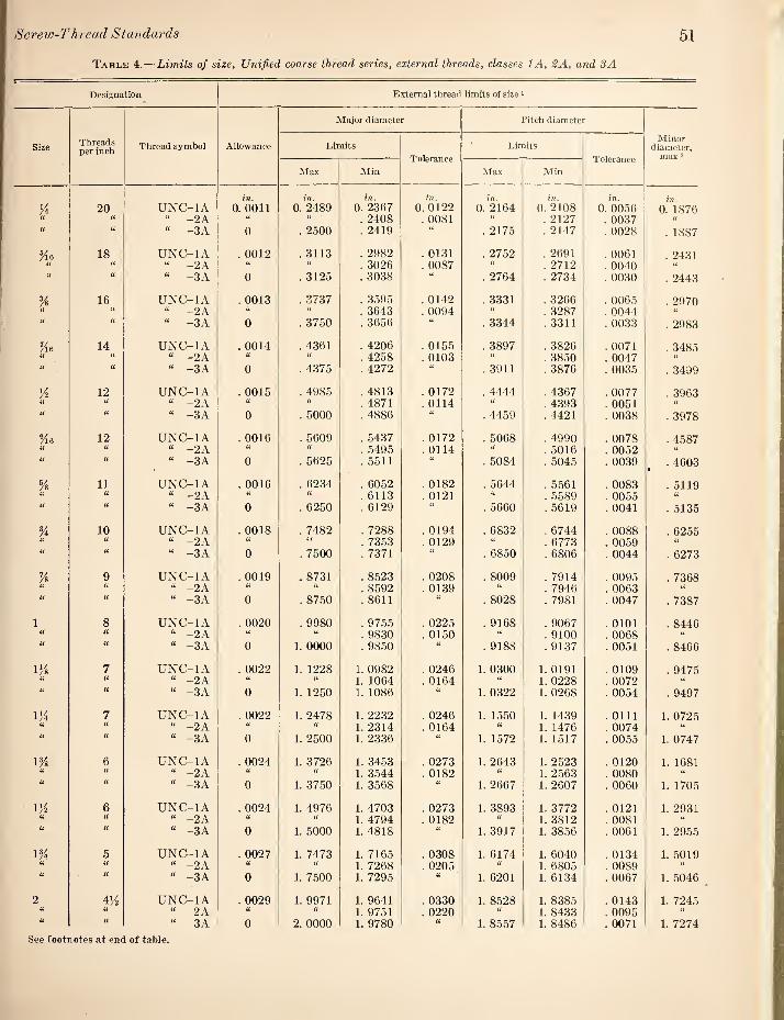
Screio-Thread Standards 51
Table 4.—Liinits of size, Unified coarse thread series, external threads, classes lA, 2A, and 3A
Designation External thread liinits of size >
Major diameter Pitch diameter
Size Threads per inch Thread symbol Allowance Limits
Tolerance Limits
Tolerance
Minor diameter,
max 2 Max Min Max Min
20 UNC-IA in.
0. 0011 in.
0. 2489 in.
0. 2367 in.
0. 0122 in.
0. 2164 !7?.
0. 2108 in.
0. 0056 in.
0. 1876 (( a “ -2A “ “ . 2408 . 0081 “ . 2127 . 0037
u “ -3 A 0 . 2500 . 2419 a . 2175 . 2147 . 0028 . 1887
Vi6 18 UNC-IA . 0012 . 3113 . 2982 . 0131 . 2752 . 2691 . 0061 ■ a a “ -2 A a . 3026 . 0087 . 2712 . 0040
u u “ -3A 0 . 3125 . 3038 u . 2764 . 2734 . 0030 . 2443
% 16 UNC-IA . 0013 . 3737 . 3595 . 0142 . 3331 . 3266 . 0065 . 2970 a “ -2A . 3643 . 0094 a . 3287 . 0044
a “ -3A 0 . 3750 . 3656 U . 3344 . 3311 . 0033 . 2983
Vie 14 UNC-IA . 0014 . 4361 . 4206 . 0155 . 3897 . 3826 . 0071 . 3485 i( U “ -2A “ . 4258 . 0103 . 3850 . 0047 a u “ -3 A 0 . 4375 . 4272 . 3911 . 3876 . 0035 . 3499
H 12 UNC-IA . 0015 . 4985 . 4813 . 0172 . 4444 . 4367 . 0077 . 3963 <( U “ -2A a “ . 4871 . 0114 . 4393 . 0051 “ u u “ -3A 0 . 5000 . 4886 “ . 4459 . 4421 . 0038 . 3978
Yie 12 UNC-IA . 0016 . 5609 . 5437 . 0172 . 5068 . 4990 . 0078 . 4587 U “ -2 A u . 5495 . 0114 a . 5016 . 0052 u “ -3A 0 . 5625 . 5511 U . 5084 . 5045 . 0039 . 4603 •
Ys 11 UNC-IA . 0016 . 6234 . 6052 . 0182 . 5644 . 5561 . 0083 . 5119 u U “ -2A u “ . 6113 . 0121 “ . 5589 . 0055 u a “ -3A 0 . 6250 . 6129 (( . 5660 . 5619 . 0041 . 5135
% 10 UNC-IA . 0018 . 7482 . 7288 . 0194 . 6832 . 6744 . 0088 . 6255 ii “ -2A . 7353 . 0129 (i . 6773 . 0059 U
(1 a “ -3 A 0 . 7500 . 7371 . 6850 . 6806 . 0044 . 6273
Vs 9 UNC-IA . 0019 . 8731 . 8523 . 0208 . 8009 . 7914 . 0095 . 7368 u a “ -2A . 8592 . 0139 “ . 7946 . 0063 (i a “ -3A 0 . 8750 . 8611 a . 8028 . 7981 . 0047 . 7387
1 8 UNC-IA . 0020 . 9980 . 9755 . 0225 . 9168 . 9067 . 0101 . 8446 a ii “ -2 A “ a . 9830 . 0150 “ . 9100 . 0068 ti a “ -3 A 0 1. 0000 . 9850 . 9188 . 9137 . 0051 . 8466
iVs 7 UNC-IA . 0022 1. 1228 1. 0982 . 0246 1. 0300 1. 0191 . 0109 . 9475 u “ -2 A U “ 1. 1064 . 0164 a 1. 0228 . 0072 u <( “ -3 A 0 1. 1250 1. 1086 1. 0322 1. 0268 . 0054 . 9497
UA 7 UNC-IA . 0022 1. 2478 1. 2232 . 0246 1. 1550 1. 1439 . 0111 1. 0725 a a “ -2A U U 1. 2314 . 0164 It 1. 1476 . 0074 u a “ -3A 0 1. 2500 1. 2336 1. 1572 1. 1517 . 0055 1. 0747
lYs 6 UNC-IA . 0024 1. 3726 1. 3453 . 0273 1. 2643 1. 2523 . 0120 1. 1681 (( H “ -2A a 1. 3544 . 0182 “ 1. 2563 . 0080 a a “ -3A 0 1. 3750 1. 3568 “ 1. 2667 1. 2607 . 0060 1. 1705
UA 6 UNC-IA . 0024 1. 4976 1. 4703 . 0273 1. 3893 1. 3772 . 0121 1. 2931 u a “ -2 A 1. 4794 . 0182 U 1. 3812 . 0081 a
a a “ -3A 0 1. 5000 1. 4818 1. 3917 1. 3856 . 0061 1. 2955
1% 5 UNC-IA . 0027 1. 7473 1. 7165 . 0308 1. 6174 1. 6040 . 0134 1. 5019 u <( “ -2A “ 1. 7268 . 0205 1. 6805 . 0089 U (C “ -3A 0 1. 7500 1. 7295 a 1. 6201 1. 6134 . 0067 1. 5046
2 4A UNC-IA . 0029 1. 9971 1. 9641 . 0330 1. 8528 1. 8385 . 0143 1. 7245 (( n “ 2 A “ ll 1. 9751 . 0220 U 1. 8433 . 0095 U (( “ 3A 0 2. 0000 1. 9780 U 1. 8557 1. 8486 . 0071 1. 7274
See footnotes at end of table.
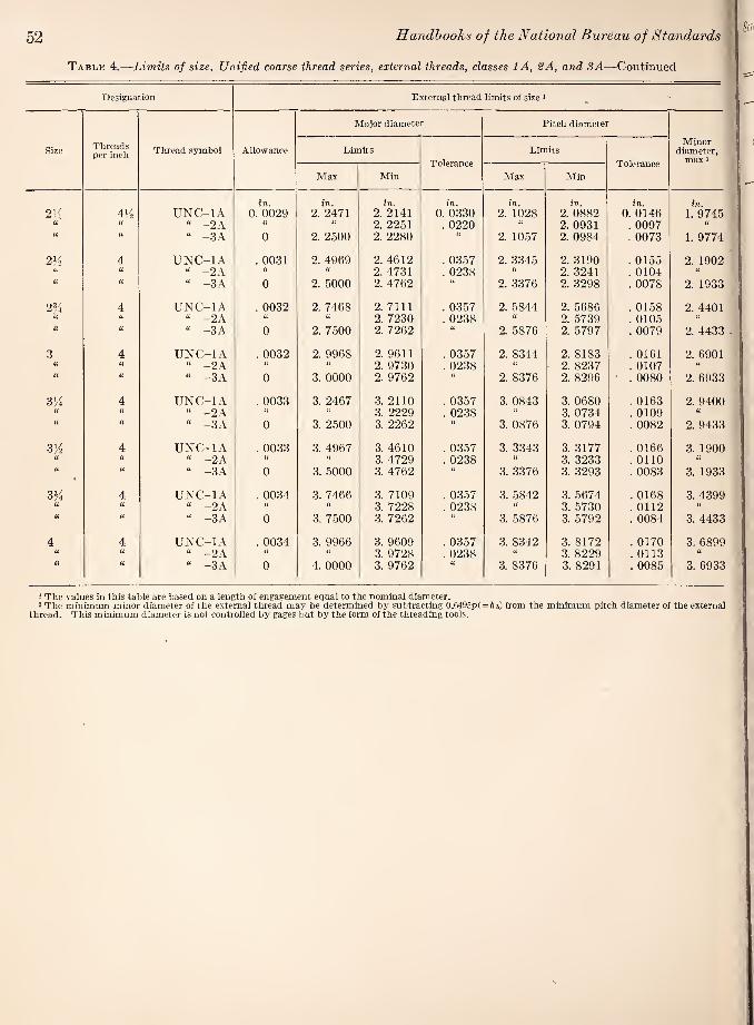
52 Handbooks of the National Bureau of Standards
Table 4.—Limits of size, Unified coarse thread series, external threads, classes lA, 2A, and 3A—Continued
Designation External thread limits of size *
Major diameter Pitch diameter
Size Threads per inch Thread symbol Allowance Limits
Tolerance Limits
Tolerance
Minor diameter,
max *
Max Min Max Min
2’:i 41^2 UNC-IA in.
0. 0029 in.
2. 2471 in.
2. 2141 in.
0. 0330 in.
2. 1028 in.
2. 0882 in.
0. 0146 in.
1.9745 a i( “ -2 A a n 2. 2251 . 0220 a 2. 0931 . 0097 a “ -3A 0 2. 2500 2. 2280 2. 1057 2. 0984 . 0073 1.9774
4 UNC-IA . 0031 2. 4969 2. 4612 . 0357 2. 3345 2. 3190 . 0155 2. 1902 U “ -2 A u U 2. 4731 . 0238 a 2. 3241 . 0104 (i “ -3 A 0 2. 5000 2. 4762 a 2. 3376 2. 3298 . 0078 2. 1933
234 4 UNC-IA . 0032 2. 7468 2. 7111 . 0357 2. 5844 2. 5686 . 0158 2. 4401 a U “ -2 A U 2. 7230 . 0238 “ 2. 5739 . 0105 a a “ -3 A 0 2. 7500 2. 7262 2. 5876 2. 5797 . 0079 2. 4433
3 4 UNC-IA . 0032 2. 9968 2. 9611 . 0357 2. 8344 2. 8183 . 0161 2. 6901 a “ -2A “ 2. 9730 . 0238 2. 8237 . 0107 a a “ -3A 0 3. 0000 2. 9762 a 2. 8376 2. 8296 . 0080 2. 6933
3/4 4 UNC-IA . 0033 3. 2467 3. 2110 . 0357 3. 0843 3. 0680 . 0163 2. 9400 u “ -2A U U 3. 2229 . 0238 a 3. 0734 . 0109
u i( “ -3 A 0 3. 2500 3. 2262 (( 3. 0876 3. 0794 . 0082 2. 9433
3^2 4 UNC-IA . 0033 3. 4967 3. 4610 . 0357 3. 3343 3. 3177 . 0166 3. 1900 U (1 “ -2A “ a 3. 4729 . 0238 3. 3233 . 0110 U u “ -3A 0 3. 5000 3. 4762 3. 3376 3. 3293 . 0083 3. 1933
3% 4 UNC-IA . 0034 3. 7466 3. 7109 . 0357 3. 5842 3. 5674 . 0168 3. 4399 a ti “ -2A a a 3. 7228 . 0238 U 3. 5730 . 0112 U
u i( “ -3A 0 3. 7500 3. 7262 3. 5876 3. 5792 . 0084 3. 4433
4 4 UNC-IA . 0034 3. 9966 3. 9609 . 0357 3. 8342 3. 8172 . 0170 3. 6899 u « “ -2A ii a 3. 9728 . 0238 3. 8229 . 0113 “ a (i “ -3A 0 4. 0000 3. 9762 U 3. 8376 3. 8291 . 0085 3. 6933
1 The values in this table are based on a length of engagement equal to the nominal diameter. 2 The minimum minor diameter of the external thread may be determined by subtracting 0.6495p(=A6) from the minimum pitch diameter of the external
thread. This minimum diameter is not controlled by gages but by the form of the threading tools.
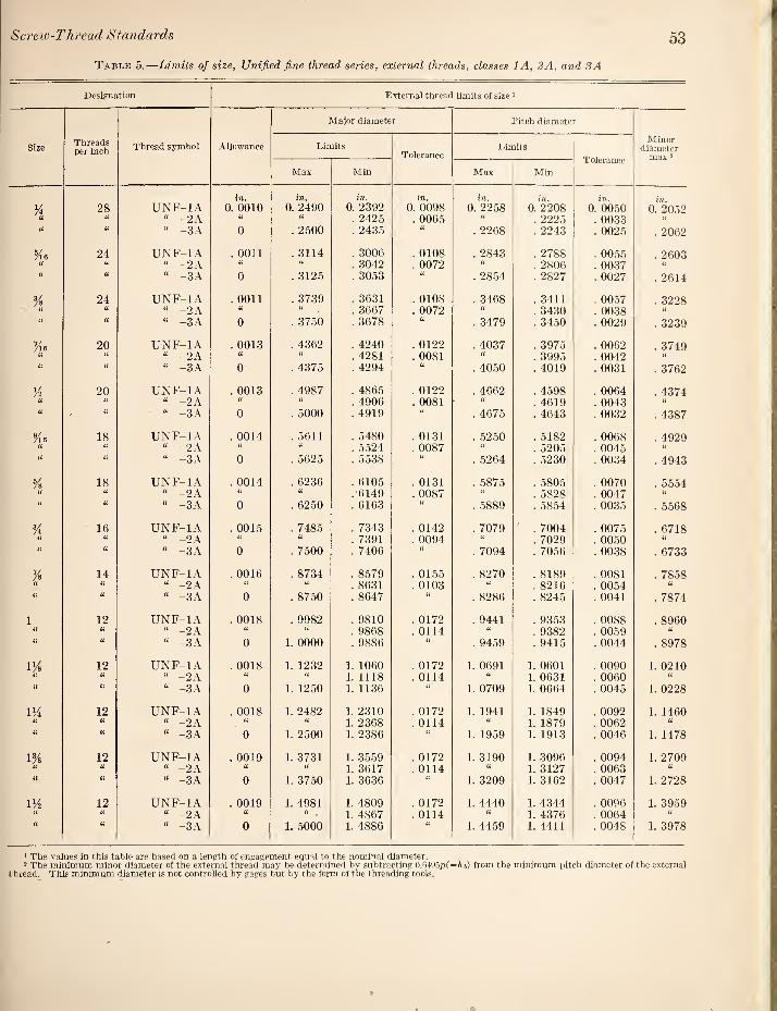
Screw-Thread Standards 53
Table 5.—Limits of size, Unified fine thread series, external threads, classes lA, 2A, and 3A
Designation External thread limits of size 1 Major diameter Pitch diameter
Size Threads per inch Thread symbol Allowance Limits
Tolerance Limits
Tolerance
Minor diameter
max 2
Max Min Max Min
y4 28 UNF-IA in. 0. 0010
in.
0. 2490 in.
0. 2392 in.
0. 0098 in.
0. 2258 in. 0. 2208
in.
0. 0050 in.
0. 2052 u U “ -2 A . 2425 . 0065 u . 2225 . 0033 ii
u “ -3A 0 . 2500 . 2435 . 2268 . 2243 . 0025 . 2062
Me 24 UNF-IA . 0011 . 3114 . 3006 . 0108 . 2843 . 2788 . 0055 . 2603 H “ -2 A “ . 3042 . 0072 ii . 2806 . 0037 U “ -3A 0 . 3125 . 3053 . 2854 . 2827 . 0027 . 2614
% 24 UNF-IA . 0011 . 3739 . 3631 . 0108 . 3468 . 3411 . 0057 . 3228
U “ -2 A “ . 3667 . 0072 . 3430 . 0038 ii
u (i « -3A 0 . 3750 . 3678 . 3479 . 3450 . 0029 . 3239
Me 20 UNF-IA . 0013 . 4362 . 4240 . 0122 . 4037 . 3975 . 0062 . 3749 U “ -2 A (1 (1 . 4281 . 0081 ii . 3995 . 0042
il ii “ -3A 0 . 4375 . 4294 . 4050 . 4019 . 0031 . 3762
Vz 20 UNF-IA . 0013 . 4987 . 4865 . 0122 . 4662 . 4598 . 0064 . 4374 “ -2A . 4906 . 0081 a . 4619 . 0043
a “ -3 A 0 . 5000 . 4919 U . 4675 . 4643 . 0032 . 4387
Me 18 UNF-IA . 0014 . 5611 . 5480 . 0131 . 5250 . 5182 . 0068 . 4929 (1 U “ -2 A “ “ . 5524 . 0087 H . 5205 . 0045 a
it “ -3 A 0 . 5625 . 5538 . 5264 . 5230 . 0034 . 4943
% 18 UNF-IA . 0014 . 6236 . 6105 . 0131 . 5875 . 5805 . 0070 . 5554 U “ -2A U .6149 . 0087 “ . 5828 . 0047 ii
a a “ -3A 0 . 6250 . 6163 . 5889 . 5854 . 0035 . 5568
% 16 UNF-IA . 0015 . 7485 . 7343 . 0142 . 7079 . 7004 . 0075 . 6718 u ii “ -2A . 7391 . 0094 . 7029 . 0050 u (1 “ -3 A 0 . 7500 . 7406 . 7094 . 7056 . 0038 . 6733
Vs 14 UNF-IA . 0016 . 8734 . 8579 . 0155 . 8270 . 8189 . 0081 . 7858 (i U “ -2 A . 8631 . 0103 ii . 8216 . 0054 (( a (i “ -3A 0 . 8750 . 8647 . 8286 . 8245 . 0041 . 7874
1 12 UNF-IA . 0018 . 9982 . 9810 . 0172 . 9441 . 9353 . 0088 . 8960 a “ -2 A (( . 9868 . 0114 (( . 9382 . 0059 “ a a “ -3 A 0 1. 0000 . 9886 it . 9459 . 9415 . 0044 . 8978
1% 12 UNF-IA . 0018 1. 1232 1. 1060 . 0172 1. 0691 1. 0601 . 0090 1. 0210 a a “ -2A u 1. 1118 . 0114 U 1. 0631 . 0060 “ it a “ -3A 0 1. 1250 1. 1136 a 1. 0709 1. 0664 . 0045 1. 0228
1% 12 UNF-IA . 0018 1. 2482 1. 2310 . 0172 1. 1941 1. 1849 . 0092 1. 1460 (C a “ -2A “ 1. 2368 . 0114 (( 1. 1879 . 0062 “ u (( « -3A 0 1. 2500 1. 2386 U 1. 1959 1. 1913 . 0046 1. 1478
1% 12 UNF-IA . 0019 1. 3731 1. 3559 . 0172 1. 3190 1. 3096 . 0094 1. 2709 <6 (i “ -2A i( 1. 3617 . 0114 1. 3127 . 0063 iC (i “ -3A 0 1. 3750 1. 3636 ii 1. 3209 1. 3162 . 0047 1. 2728
VA 12 UNF-IA . 0019 1. 4981 1. 4809 . 0172 1. 4440 1. 4344 . 0096 1. 3959 u U “ -2A (i U 1. 4867 . 0114 “ 1. 4376 . 0064 “
u “ -3A 0 1. 5000 1. 4886 1. 4459 1. 4411 . 0048 1. 3978
1 The values in this table are based on a length of engagement equal to the nominal diameter. 2 The minimum minor diameter of the external thread may be determined by subtracting 0.6495p{=ft6) from the minimum idtch diameter of the external
thread. This minimum diameter is not controlled by gages but by the form of the threading tools.

54 llandhoohs of the National Bureau of Standards
Table 6.—Limits of size, Unified coarse thread series, internal threads, classes IB, 2B, and SB
Designation Internal thread limits of size ‘
Minor diameter Pitch diameter
Size Threads per inch Thread symbol Limits
Tolerance Limits
Tolerance
Major di¬ ameter Min 2
Min Max Min Max
K4 20 UNC-IB in.
0, 1959 in.
0. 2067 in.
0. 0108 in.
0. 2175 in.
0. 2248 in.
0. 0073 in. 0. 2500
u “ “ -2B a a “ . 2223 . 0048 a u U “ -3B u a . 2211 . 0036 C(
Ke 18 UNC-IB . 2524 . 2630 . 0106 . 2764 . 2843 . 0079 . 3125 iL u “ -2B a a U . 2817 . 0053 “
“ “ -3B u a a . 2803 . 0039 ((
% 16 UNC-IB . 3073 . 3182 . 0109 . 3344 . 3429 . 0085 . 3750 “ -2B a “ . 3401 . 0057 a “ -3B “ a . 3387 . 0043 a
Mo 14 UNC-IB . 3602 . 3717 . 0115 . 3911 . 4003 . 0092 . 4375 “ -2B a a a . 3972 . 0061 a
U “ “ -3B a a a a . 3957 . 0046 a
¥2 12 UNC-IB . 4098 . 4223 . 0125 . 4459 . 4559 . 0100 . 5000 a “ -2B (i “ a . 4525 . 0066 a
u u “ -3B U a a a . 4509 . 0050 a
12 UNC-IB . 4723 . 4843' . 0120 . 5084 . 5186 . 0102 . 5625 U (( “ -2B U . 5152 . 0068 a u “ -3B a . 5135 . 0051 a
% 11 UNC-IB . 5266 . 5391 . 0125 . 5660 . 5767 . 0107 . 6250 “ “ -2B “ a a . 5732 . 0072
li “ -3B a a a . 5714 . 0054 a
% 10 UNC-IB . 6417 . 6545 . 0128 . 6850 . 6965 . 0115 . 7500 “ -2B a a . 6927 . 0077
u “ “ -3B a a a . 6907 . 0057
% 9 UNC-IB . 7547 . 7681 . 0134 . 8028 . 8151 . 0123 . 8750 u u “ -2B “ “ . 8110 . 0082 a u “ “ -3B a a “ a . 8089 . 0061 a
1 8 UNC-IB . 8647 . 8797 . 0150 . 9188 . 9320 . 0132 1. 0000 u a “ -2B U a a a . 9276 . 0088 “ u “ -3B a a . 9254 . 0066
7 UNC-IB . 9704 . 9875 . 0171 1. 0322 1. 0463 . 0141 1. 1250 a “ -2B a a 1. 0416 . 0094 “ u U “ -3B a a a H 1. 0393 . 0071 a
IM 7 UNC-IB 1. 0954 1. 1125 . 0171 1. 1572 1. 1716 . 0144 1. 2500 “ -2B a a a 1. 1668 . 0096 a
u <( “ -3B a a a a 1. 1644 . 0072
1% 6 UNC-IB 1. 1946 1. 2146 . 0200 1. 2667 1. 2822 . 0155 1. 3750 a “ -2B a a a a 1. 2771 . 0104 a
U “ -3B a “ 1. 2745 . 0078
v/2 6 UNC-IB 1. 3196 1. 3396 . 0200 1. 3917 1. 4075 . 0158 1. 5000 “ “ -2B a “ 1. 4022 . 0105 a
“ -3B a a a a 1. 3996 . 0079 a
1% 5 UNC-IB 1. 5335 1. 5575 . 0240 1. 6201 1. 6375 . 0174 1. 7500 a U “ -2B a a 1. 6317 . 0116 a li U “ -3B a
“ u 1. 6288 . 0087
2 4M UNC-IB 1. 7594 1. 7861 . 0267 1. 8557 1. 8743 . 0186 2. 0000 “ -2B a 1. 8681 . 0124 a
“ “ -3B u “ “ “ 1. 8650 . 0093 a
Footnotes at end of table.
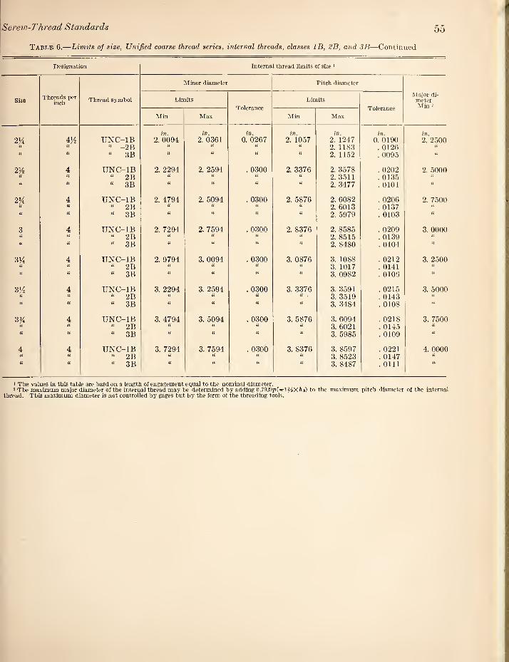
Screw-Thread Standards 55
Table 6.—Limits of size, Unified coarse thread series, internal threads, classes IB, SB, and SB—Continued
Designation Internal thread limits of size ■
Size Threads per
inch Thread sj'mbol
Minor diameter Pitch diameter
Major di¬ meter Min 2
Limits
Tolerance
Limits
Tolerance
Min Max Min Max
in. in. in. in. in. in. in.
2K 4>^ UNC-IB 2. 0094 2. 0361 0. 0267 2. 1057 2. 1247 0. 0190 2. 2500 U a “ -2B “ U ii 2. 1183 . 0126 a u « “ -3B ii ii ti ti 2. 11.52 . 0095 ii
21/2 4 UNC-IB 2. 2294 2. 2594 . 0300 2. 3376 2. 3578 . 0202 2. 5000 a a “ 2B ii ti a 2. 3511 . 0135 a a “ 3B ti ti it ii 2. 3477 . 0101 ii
2% 4 UNC-IB 2. 4794 2. 5094 . 0300 2. 5876 2. 6082 . 0206 2. 7500 U a “ 2B it “ ti 2. 6013 . 0137 “ u a “ 3B ti a ti ii 2. 5979 . 0103 ti
3 4 UNC-IB 2. 7294 2. 7594 . 0300 2. 8376 2. 8585 . 0209 3. 0000 ii ii “ 2B ii “ 2. 8515 . 0139 a u “ 3B ti ti ti 2. 8480 . 0104 ii
31/ 4 UNC-IB 2. 9794 3. 0094 . 0300 3. 0876 3. 1088 . 0212 3. 2500 ti “ 2B “ ti 3. 1017 . 0141 a
u a “ 3B ii ti ii ti 3. 0982 . 0105 ii
314 4 UNC-IB 3. 2294 3. 2594 . 0300 3. 3376 3. 3591 . 0215 3. 5000 u ti « 2B ti ii ti ii . 3. 3519 . 0143 u a “ 3B ii ti it ii 3. 3484 . 0108
3% 4 UNC-IB 3. 4794 3. 5094 . 0300 3. 5876 3. 6094 . 0218 3. 7500 u ft “ 2B “ “ 3. 6021 . 0145 (1 a “ 3B ii ii 3. 5985 . 0109 ti
4 4 UNC-IB 3. 7294 3. 7594 . 0300 3. 8376 3. 8597 . 0221 4. 0000 U a “ 2B ti ti 3. 8523 . 0147 ii
(i ti « 3B ii ii ii 3. 8487 . 0111 ti
1 The values in this table are basd on a length of engagement equal to the nominal diameter. 2 The maximum major diameter of the internal thread may be determined by adding 0.7939p(=l?^Xftb) to the maximum pitch diameter of the internal
thread. This maximum diameter is not controlled by gages but by the form of the threading tools.

56 Handboohs of the National Bureau of Standards^
Table 7.—Limits of size. Unified fine thread series, internal threads, classes IB, 2B, and SB
Designation Internal thread limits of size >
Size Threads per inch Thread symbol
Minor diameter Pitch diameter
Major di¬ ameter Min 2
Limits Tolerance
Limits Tolerance
Min Max Min Max
in. in. in. in. in. in. in.
28 UNF-IB 0. 2113 0. 2190 0. 0077 0. 2268 0. 2333 0. 0065 0. 2500 (i U “ -2B U a a U . 2311 . 0043 U
{( (1 “ -3B a a u a . 2300 . 0032 a
Via 24 UNF-IB . 2674 . 2754 . 0080 . 2854 . 2925 . 0071 . 3125 U “ -2B U a U . 2902 . 0048 U
a ({ “ -3B a U . 2890 . 0036 a
% 24 UNF-IB . 3299 . 3372 . 0073 . 3479 . 3553 . 0074 . 3750 u “ -2B (( U . 3528 . 0049 U a a “ -3B U U (1 U . 3516 . 0037 u
Vis 20 UNF-IB . 3834 . 3916 . 0082 . 4050 . 4131 . 0081 . 4375 a a “ -2B U U a “ . 4104 . 0054 il
a a “ -3B u U (( U . 4091 . 0041 ((
% 20 UNF-IB . 4459 . 4537 . 0078 . 4675 . 4759 . 0084 . 5000 (1 “ -2B U U . 4731 . 0056 u
a u “ -3B U U U U . 4717 . 0042 i(
%6 18 UNF-IB . 5024 . 5106 . 0082 . 5264 . 5353 . 0089 . 5625 u (1 “ -2B a a . 5323 . 0059 U
a a “ -3B U u a <( . 5308 . 0044 a
Vs 18 UNF-IB . 5649 . 5730 . 0081 . 5889 . 5980 . 0091 . 6250 a “ -2B a U . 5949 . 0060 tc
a a “ -3B u (( U . 5934 . 0045 ((
% 16 UNF-IB . 6823 . 6908 . 0085 . 7094 . 7192 . 0098 . 7500 a a “ -2B a (( « . 7159 . 0065 U
li “ -3B u U U (i . 7143 . 0049 ((
Vs 14 UNF-IB . 7977 . 8068 . 0091 . 8286 . 8392 . 0106 . 8750 u U “ -2B u a u a . 8356 . 0070 <(
a n “ -3B a u a . 8339 . 00.53 <{
1 12 UNF-IB . 9098 . 9198 . 0100 . 9459 . 9573 . 0114 1. 0000 (t U “ -2B a u a . 9535 . 0076 ((
u u “ -3B a u (( . 9516 . 0057 ((
12 UNF-IB 1. 0348 1. 0448 . 0100 1. 0709 1. 0826 . 0117 1. 1250 a “ -2B a “ U 1. 0787 . 0078 u
(1 U “ -3B u u a 1. 0768 . 0059 u
UA 12 UNF-IB 1. 1598 1. 1698 . 0100 1. 1959 1. 2079 . 0120 1. 2500 u U “ -2B u a 1. 2039 . 0080 u
u u “ -3B (( a it a 1. 2019 . 0060 u
IVs 12 UNF-IB 1. 2848 1. 2948 . 0100 1. 3209 1. 3332 . 0123 1. 3750 (( “ -2B U u 1. 3291 . 0082 a
u a “ -3B ic U u 1. 3270 . 0061 u
UA 12 UNF-IB 1. 4098 1. 4198 . 0100 1. 4459 1. 4584 . 0125 1. 5000 u U “ -2B “ “ u 1. 4542 . 0083 a a u “ -3B (( U U 1. 4.522 . 0063 a
1 The values in this table are based on a length of engagement equal to the nominal diameter. 2 The maximu major diameter of the internal tread may be determined by adding 0.7939p(=l 2/9Xftt) to the maximum pitch diameter of the internal thread.
This maximum diameter is not controlled by gages but by the form of the threading tools.

Table
8.—
Incre
ments i
n p
itch-d
iam
ete
r to
lera
nce
form
ula
(PD
tole
rance
= C
(0.0
015
+ 0
.0015/^
, + 0
.015
Screw-Thread Standards 57
o
iC o o
in.
0.
000S
08
.
00
08
67
. 0
00
93
8
. 0
01
02
5
. 0
01
13
6
. 001204
. 0
01
28
2
. 0
01
37
6
. 0
01
48
8
. 0
01
62
7
. 0
01
80
3
. 0
02
03
6
. 0
02
18
4
. 0
02
36
2
. 0
02
58
2
. 0
02
71
3
. 0
02
86
2
. 0
03
03
3
. 003232
. 0
03
46
7
. 0
03
75
0
. 0
04
09
9
. 0
04
54
3
. 0
05
13
0
. 0
05
50
3
. 0
05
95
3
Ah
Th
read
s per
inch
O (M O 00 00 t> CO lO
o CO oq 00 T}^ CO CO (M
O 00 CO (N (N ^ . I-I
CO (N ^ O 05 1—1\
00 i> CO to
1 t 1 1 1(11
^ lilt 1 1 1 1 1 1 1 1
lO o
in.
003092
0
03
13
7
003182
0
03
22
6
00
32
69
00
33
12
0
03
35
4
00
33
96
0
03
43
7
00
34
78
00
35
18
0
03
55
8
00
35
97
0
03
63
6
00
36
74
00
38
24
0
03
96
9
00
41
08
0
04
24
3
00
43
73
00
45
00
0
04
62
3
00
47
43
004861
0
04
97
5
00
50
87
005196
o o 1 1 1 1 1 1
o o o o o. O lO o lO o lO l> o O
gj (M CO lO CO I>
O O O O O lO O to O lO l>* O <M ^ 00 O ^ CQ CO
O O O O O o to O to o O IM to O to CO 00 o
O O O O O o o o o o O O O O O to o to o to
C O O O O o o o o o C O O O O O to O to o 50
00
0000
TjH TtH Tf lO to IC lO »0 tO to tO CO CO l> CO GO 05 05 o O (N 1 ' >
14 lO o 00
1677
00
1701
00
1718
00
1759
00
1793
0017
98
0018
37
0019
12
0019
36
0019
84
0020
54
0021
21
0021
87
0022
50
0023
12
0023
72
0024
30
0024
87
0025
43
0025
98
0026
52
0027
04
0027
39
0027
56
0028
06
0028
56
0029
05
0029
53
0030
00
0030
47
a
a 0? fcuO e3 &j0 a
o O
4 in.
1. 2
500
1. 2
857
1. 3
125
1. 3
750
1. 4
286
1. 4
375
1. 5
000
1. 6
250
1. 6
667
1. 7
500
1. 8
750
2. 0
000
2. 1
250
2. 2
500
2. 3
750
2. 5
000
2. 6
250
2. 7
500
2. 8
750
3. 0
000
3. 1
250
3. 2
500
3. 3
333
3. 3
750
3. 5
000
3. 6
250
3. 7
500
3. 8
750
4. 0
000
4. 1
250
XJ
a 3 »o
o
in.
0008
50
0008
59
0008
80
0008
96
0008
99
0009
19
0009
37
0009
56
0009
68
0009
74
0009
92
0010
06
0010
61
0011
18
0011
25
0011
86
0012
03
0012
44
0012
68
0012
99
0013
52
0013
69
0014
03
0014
23
0014
52
0015
00
0015
46
0015
81
0015
91
0016
35
o O
4
^ 00 ^ ^OOCOt^O'- <M (N TfH lO lO CO CO CO CO CO
O CO CO 05 lO O CO CO 1—' !> 05 o 1-1 (M CO CO
to O O CO to O O to <N
CO to o to CO to to to
O 05 to CO O tc (N O (M Tfi 00 --H to CO CO CO I>
tO CO O O tO (N CO tc o t> ^ CO i> o CO (XI GO GO 05 05 00
00
0625
nil
12
50
1875
O ^ r-l ^
»o o o d
. 00
0367
. 0
0037
5 . 00
0405
. 00
0419
. 00
0440
. 00
0459
. 00
0472
.
0004
96
. 000
502
. 000
503
. 000
530
. 000
557
. 000
562
. 00
0593
.
0006
01
. 00
0607
. 00
0622
. 00
0650
.
0006
54
. 00
0676
. 00
0697
. 00
0702
. 00
0712
. 00
0726
. 00
0750
. 00
0773
.
0007
91
. 00
0796
. 00
0817
. 00
0839
4
0*00^0 O (M CO GO CO
• O CD I> 00 O O O O O
GO O O IC CO 05 05 (M CS 05 05 o -H ^ o o ^ ^
O O CO CO to 00 O CO o
CO to CO
O 05 to O ^ ^ 1> O CO
CO N. 00 05 o --H ^ ^ 1-H (M
O 00 O O CO 00 to o ,-H ^ CO to (M (M CQ (M
CO GO CO 05 to to i-H CO Ol CO l> 00 05 i-H <N (M (01 (05 CO
0.00
15
in.
. 00
2356
. 0
0238
1 . 0
0243
0 . 0
0247
6 . 0
0252
1
. 002
565
. 00
2607
. 0
0264
8 . 0
0268
7 . 0
0272
6
. 002
869
. 00
3000
. 0
0312
0 . 0
0323
2 . 0
0343
4
. 003
615
. 003
780
. 003
931
. 00
4072
.
0043
27 1 1 1 1 1
1 1 1 1 1 1 1 1 1 1 1 1 1 1 1 1 ( 1 1 ( 1 I 1 1 1 1 1 1 T ( 1 I 1 1 1 1 1 1 1 (
( 1 I 1 1 (1(11 1 ( 1 ( ( (1(11 (((II 1 1 1 t 1 11(11 1 1 1 1 1 1 1 ( 1 1
q
O O O O O ^ o o o o
O ^ O 00 O »0 t>
O O O O O o o o o o O to o to O 0(N tOt^O
O O O O O o o o o o O O O O O o o o o o
O O O O O o o o o o O O O O O o o o o o
1 1 1 1 1 11(11 111(1 ( ( 1 ( (
1 1 1 1 I 1 1 1 1 1 1 1 1 ( 1 1 1 1 I 1
CO Ttn TjH lO to iO to CO !>• 00 05 O (N CO 00 O 1-H 1-H ^ C<l (M
1 ( f 1 ( 1 1 ( 1 ( 1 1 1 1 1 1 1 1 1 1
iq
O in
0016
42
0016
68
0016
93
0017
17
0017
41
0017
64
0017
86
0018
08
0018
29
0018
50
0018
70
0018
90
0019
09
0019
28
0019
47
0019
66
0019
84
0020
01
0020
19
0020
361
0020
69
0021
02
0021
33
0021
63
0021
93
0022
22
0022
50
0022
77
0023
04
0023
30
H) a
d O
c3 5
q
lO O lO O lO <M lO O (TQ
t-. CO O CO ^ CO CO *0 iO
O to O to o to O (N to (M 00 to ^ CO CO 1> 00 00
to o to o to l>OC<JtOt^ CO O CO (M 00 05 O O ^
o to O to O O to o to ^ 1> CO o
CO CO to
O O O O O to O to O to (N to 1> O CO 1> 00 O
O O O O O o to O to o to O (05 to 05 CO to CO t>
^ ^ ^ ^ (N (M IM (N CN (N c4 (M* (M’ (N CO CO CO CO CO CO CO
iq
o in.
0005
87
0005
95
0006
27
0006
62
0006
82
0006
94
0007
23
0007
50
0007
75
0008
21
0008
59
0008
62
0009
00
0009
45
0010
18
0010
82
0011
39
0011
91
0012
38
0012
82
0013
24
0013
63
0014
00
0014
35
0014
68
0015
00
0015
31
0015
60
0015
88
0016
16
d o
q
O lO O O 00 O <M CO CO CO ^ CO r>- 00 OC)
g- o o o o o o
O O O O O 05 (N to 00 05 ^ (N CO CO O ^ ^ T-l ,-H
to O O O to O CO O <N
00 05 ^ to ^ ^ ^ (N (N CO
o to O to O to O (M to
CO o CO CO to to CO
to O tO o to i> o (N to i> GO to i-H CO CO 00 00 05
1. 0
000
1. 0
625
1. 1
250
1. 1
875
1. 2
500
O


K'-
i'jV
!>»'
W.'.
S'-'.

t
■
I
r
i
" , ■, 1^'
m' v r. ■'':. ■'' ; V'

.Vi'''i..;'■- I 'jA