Embed Size (px)
Citation preview

ML-175Parts Manual
Phase 7
American Dryer Corporation88 Currant Road
Fall River, MA 02720-4781Telephone: (508) 678-9000 / Fax: (508) 678-9447
e-mail: [email protected]
092602DMG/wmarelli ADC Part No. 450581

Retain This Manual In A Safe Place For Future Reference
American Dryer Corporation products embody advanced concepts in engineering, design, and safety. If this product isproperly maintained, it will provide many years of safe, efficient, and trouble-free operation.
ONLY qualified technicians should service this equipment.
OBSERVE ALL SAFETY PRECAUTIONS displayed on the equipment or specified in the installation manual included withthe dryer.
The following “FOR YOUR SAFETY” caution must be posted near the dryer in a prominent location.
We have tried to make this manual as complete as possible and hope you will find it useful. ADC reserves the right to makechanges from time to time, without notice or obligation, in prices, specifications, colors, and material, and to change ordiscontinue models.
Important
For your convenience, log the following information:
DATE OF PURCHASE ____________________________ MODEL NO. __________________________________________
RESELLER’S NAME _______________________________________________________________________________________
Serial Number(s) ________________________________________________________________________________________
________________________________________________________________________________________
________________________________________________________________________________________
Replacement parts can be obtained from your reseller or the ADC factory. When ordering replacement parts from the factory,you can FAX your order to ADC at (508) 678-9447 or telephone your order directly to the ADC Parts Department at (508)678-9000. Please specify the dryer model number and serial number in addition to the description and part number, so thatyour order is processed accurately and promptly.
The illustrations on the following pages may not depict your particular dryer exactly. The illustrations are a composite of thevarious dryer models. Be sure to check the descriptions of the parts thoroughly before ordering.
“IMPORTANT NOTE TO PURCHASER”
Information must be obtained from your local gas supplier on the instructionsto be followed if the user smells gas. These instructions must be posted in aprominent location near the dryer.
ML-175
FOR YOUR SAFETY
Do not store or use gasoline orother flammable vapors andliquids in the vicinity of this orany other appliance.
POUR VOTRE SÉCURITÉ
Ne pas entreposer ni utiliser d’essenceni d’autres vapeurs ou liquidesinflammables à proximité de cetappareil ou de tout autre appareil.

Table of Contents
Control Door Assembly .............................................................................................................................2Phase 7 OPL Microprocessor Control Panel Assembly ...............................................................................3Front Panel/Main Door Assemblies ....................................................................................................... 4, 5Main Door Switch Assembly .....................................................................................................................6Basket (Tumbler) Assembly ......................................................................................................................7Phase 7 Rotational Sensor Assembly .........................................................................................................8Lint Door Assembly .................................................................................................................................9Lint Drawer/Lint Drawer Switch Box Assemblies .................................................................................... 10Fan (Squirrel Cage) Shaft Mount Assembly .............................................................................................. 11Blower Motor Mount Assembly ............................................................................................................... 12Microprocessor Temperature Sensor Bracket Assembly ........................................................................... 13Drive Shaft Assembly ............................................................................................................................. 14Idler Shaft Assembly .............................................................................................................................. 15Speed Reducer Shaft Assembly ............................................................................................................... 16Totally Enclosed, Non-Venting (T.E.N.V.) Drive Motor Assembly .............................................................. 17Direct Spark Ignition (DSI) Burner Assembly ......................................................................................18, 19Sail Switch Assembly .............................................................................................................................. 20Air Jet Assembly .................................................................................................................................... 21Microprocessor Reversing Contactor Mounting Panel Assembly
For 208-240 Volt TransformersFor Models Mfd. as of August 29, 2002 ........................................................................................22, 23
Microprocessor Reversing Contactor Mounting Panel AssemblyFor 208-240 Volt TransformersFor Models Mfd. prior to August 29, 2002 .....................................................................................24, 25
Microprocessor Reversing Contactor Mounting Panel AssemblyFor 380-416 Volt TransformersFor Models Mfd. prior to August 29, 2002 .....................................................................................26, 27
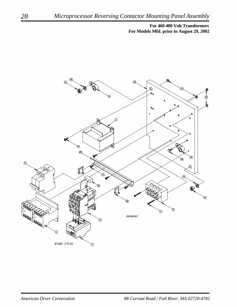
Microprocessor Reversing Contactor Mounting Panel AssemblyFor 460-480 Volt TransformersFor Models Mfd. prior to August 29, 2002 .....................................................................................28, 29
Steam Damper AssemblyFor Steam Models Only .................................................................................................................... 30
Pneumatic Valve AssemblyFor Gas Models Only ........................................................................................................................ 31
Pneumatic Valve AssemblyFor Steam Models Only .................................................................................................................... 32
Top Console Assembly ............................................................................................................................ 33FSS Temperature Probe Assembly .......................................................................................................... 34FSS Solenoid Assembly ........................................................................................................................... 35Back Guard Assemblies .....................................................................................................................36, 37

2
American Dryer Corporation 88 Currant Road / Fall River, MA 02720-4781
Control Door Assembly
Illus. No. Part No. Qty. Description
1* 883256 1 Phase 7 Control Door (gas)883322 1 Phase 7 Control Door (steam)
2 150314 4 #10-32 x 1/2” TORX Screw3 154011 4 #10-32 Multi-Thread U-Nut4 112373 1 Milnor Logo
* Specify color when ordering.

3
Telephone: (508) 678-9000 Fax: (508) 678-9447
Phase 7 OPL Microprocessor Control Panel Assembly
Illus. No. Part No. Qty. Description
1 112571 1 Phase 7 OPL Keyboard2 850980 1 Phase 7 Microprocessor Controller (computer) Panel ONLY
822754 1 Phase 7 OPL Reversing Microprocessor Controller (computer) ControlPanel Assembly Complete(includes illus. nos. 1 through 7)
3 137247 1 Phase 7 OPL Microprocessor Controller (computer) ONLY4 150005 2 #6-32 x 3/4” Phillips Round Head Machine Screw5 153010 2 #6 Star Washer6 136016 1 5-Amp Fuse7 136097 1 500-mA Fuse
4
American Dryer Corporation 88 Currant Road / Fall River, MA 02720-4781
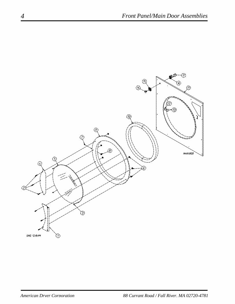
Front Panel/Main Door Assemblies

5
Telephone: (508) 678-9000 Fax: (508) 678-9447
Illus. No. Part No. Qty. Description
1 881685 1 White Main Door Hinge882296 1 Coral Wrinkle Blue Main Door Hinge
2 881740 6 1/4-20 x 5/8” White Carriage Bolt881739 6 1/4-20 x 5/8” Coral Wrinkle Blue Carriage Bolt
3 151012 1 #10-32 White Acorn Nut4 881688 1 White Main Door Handle
881737 1 Coral Wrinkle Blue Main Door Handle5 102214 1 30” Door Glass
170730 1 Door Glass Adhesive (10.3 oz. cartridge)6 881806 6 1/4-20 White Free Spin Wash Nut
882293 6 1/4-20 Coral Wrinkle Blue Free Spin Wash Nut7 150120 1 Main Door Latch Screw
(#10-32 dome hex head screw)8 151010 1 #10-32 Acorn Nut9 881689 1 White Main Door Assembly Complete
(includes illus. nos. 2 through 10)881761 1 Coral Wrinkle Blue Main Door Assembly Complete
(includes illus. nos. 2 through 10)881966 1 White Main Door Ring882305 1 Coral Wrinkle Blue Cold Rolled Steel (CRS) Large Main Door Ring
10 882411 1 Extruded Steel Door Gasket11 882503 1 White Front Panel Assembly
(includes illus. nos. 1, 15, and 16)882504 1 Coral Wrinkle Blue Front Panel Assembly
(includes illus. nos. 1, 15, and 16)12 170330 1 Friction Door Latch13 154215 2 5/32” Pop Rivet14 122351 1 “EMERGENCY STOP” (E-Stop) Push-Pull Button15 122419 1 “EMERGENCY STOP” (E-Stop) Nameplate16 132387 1 Normally Closed (N.C.) Contact Block17 132395 1 Normally Closed (N.C.) Contact Block with Base
Front Panel/Main Door Assemblies
6
American Dryer Corporation 88 Currant Road / Fall River, MA 02720-4781
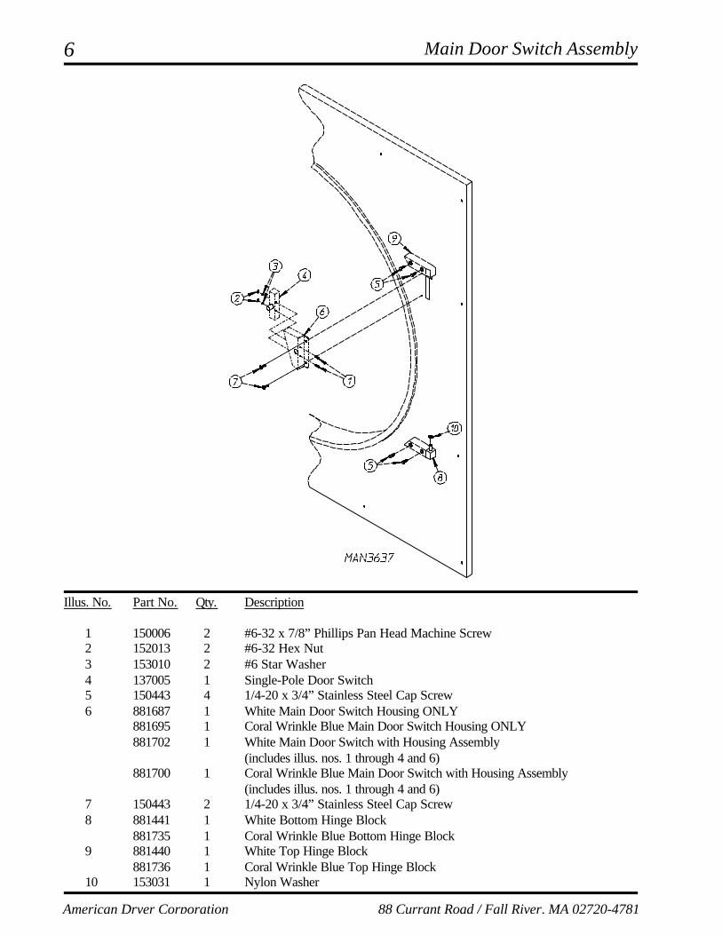
Main Door Switch Assembly
Illus. No. Part No. Qty. Description
1 150006 2 #6-32 x 7/8” Phillips Pan Head Machine Screw2 152013 2 #6-32 Hex Nut3 153010 2 #6 Star Washer4 137005 1 Single-Pole Door Switch5 150443 4 1/4-20 x 3/4” Stainless Steel Cap Screw6 881687 1 White Main Door Switch Housing ONLY
881695 1 Coral Wrinkle Blue Main Door Switch Housing ONLY881702 1 White Main Door Switch with Housing Assembly
(includes illus. nos. 1 through 4 and 6)881700 1 Coral Wrinkle Blue Main Door Switch with Housing Assembly
(includes illus. nos. 1 through 4 and 6)7 150443 2 1/4-20 x 3/4” Stainless Steel Cap Screw8 881441 1 White Bottom Hinge Block
881735 1 Coral Wrinkle Blue Bottom Hinge Block9 881440 1 White Top Hinge Block
881736 1 Coral Wrinkle Blue Top Hinge Block10 153031 1 Nylon Washer
7
Telephone: (508) 678-9000 Fax: (508) 678-9447
Illus. No. Part No. Qty. Description
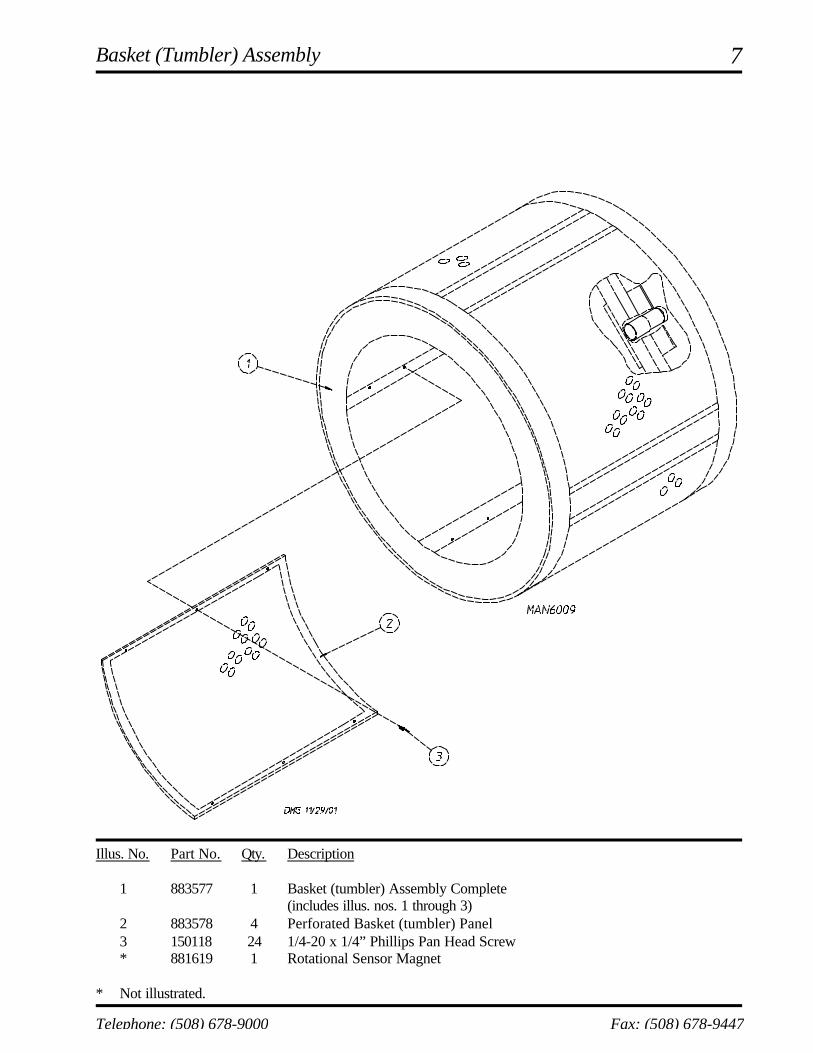
1 883577 1 Basket (tumbler) Assembly Complete(includes illus. nos. 1 through 3)
2 883578 4 Perforated Basket (tumbler) Panel3 150118 24 1/4-20 x 1/4” Phillips Pan Head Screw* 881619 1 Rotational Sensor Magnet
* Not illustrated.
Basket (Tumbler) Assembly

8
American Dryer Corporation 88 Currant Road / Fall River, MA 02720-4781
Phase 7 Rotational Sensor Assembly
Illus. No. Part No. Qty. Description
1 819064 1 Basket (tumbler) Shaft Support Assembly Complete(includes illus. nos. 1 through 8)
835339 1 Basket (tumbler) Shaft Support Bracket2 102394 2 Basket (tumbler) Friction Pad3 153005 6 3/8” Lock Washer4 150619 2 3/8-16 x 1” Tap Bolt5 153004 8 3/8” Flat Washer6 180018 4 4” x 1-1/2” Hi-Impact Wheel7 819046 1 Basket (tumbler) Adjustment Plate8 819065 1 Basket (tumbler) Shoulder Screw9 822735 1 Phase 7 Rotational Sensor Assembly10 152005 4 3/8-16 Hex Nut11 323433 2 Rear Wheel Shim

9
Telephone: (508) 678-9000 Fax: (508) 678-9447
Lint Door Assembly
Illus. No. Part No. Qty. Description
1 882497 1 White Lint Door Assembly(includes illus. nos. 1, 2, and 4)
882498 1 Coral Wrinkle Blue Lint Door Assembly(includes illus. nos. 1, 2, and 4)
2 117607 6 1/4” x 3/8” Poron Foam (sold by the foot)3 150309 5 #10-16 x 1/2” Hex Head TEK Crimptite Screw4 117604 9 Neoprene Sponge Tape (sold by the foot)
10
American Dryer Corporation 88 Currant Road / Fall River, MA 02720-4781
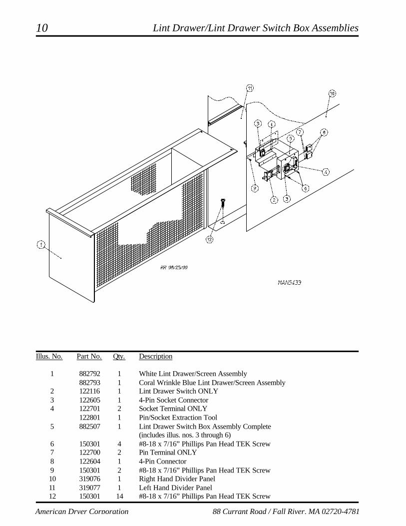
Lint Drawer/Lint Drawer Switch Box Assemblies
Illus. No. Part No. Qty. Description
1 882792 1 White Lint Drawer/Screen Assembly882793 1 Coral Wrinkle Blue Lint Drawer/Screen Assembly
2 122116 1 Lint Drawer Switch ONLY3 122605 1 4-Pin Socket Connector4 122701 2 Socket Terminal ONLY
122801 1 Pin/Socket Extraction Tool5 882507 1 Lint Drawer Switch Box Assembly Complete
(includes illus. nos. 3 through 6)6 150301 4 #8-18 x 7/16” Phillips Pan Head TEK Screw7 122700 2 Pin Terminal ONLY8 122604 1 4-Pin Connector9 150301 2 #8-18 x 7/16” Phillips Pan Head TEK Screw10 319076 1 Right Hand Divider Panel11 319077 1 Left Hand Divider Panel12 150301 14 #8-18 x 7/16” Phillips Pan Head TEK Screw

11
Telephone: (508) 678-9000 Fax: (508) 678-9447
Illus. No. Part No. Qty. Description
1 100612 1 1-1/4” Bore x 15” Diameter x 6” Blower/Fan (squirrel cage)2 821078 1 Fan Shaft Mount Assembly Complete
(includes illus. nos. 1 through 16, 18, and 19)821073 1 Fan Shaft Mount ONLY
3 117604 4 Neoprene Sponge Tape (sold by the foot)4 152006 2 1/2-20 Left Hand Jam Nut5 153065 1 1/2” Flat Washer6 882930 1 Fan Shaft Assembly
(includes illus. nos. 7, 11, and 12)7 -------- 1 1-3/8” Flange Bearing with Setscrews and Grease Fitting
(sold only as part of illus. no. 6)8 153004 4 3/8” Flat Washer9 153005 4 3/8” Lock Washer10 152005 4 3/8-16 Hex Nut11 100812 2 1-3/8” Retaining Ring12 -------- 1 1-3/8” Pillow Block Bearing (sold only as part of illus. no. 6)13 153004 2 3/8” Flat Washer14 153005 2 3/8” Lock Washer15 150617 2 3/8-16 x 1” Hex Head Bolt16 101177 1 2B x 5.8 Pulley (for gas models Only)17* 100184 2 BX-63 Cogged Belt (fan shaft to blower motor) 50/60 Hz* 100159 2 BX-61 Cogged Belt (fan shaft to blower motor) 575 Volt 60 Hz ONLY18 100706 1 5/16” x 5/16” x 1-3/8” Key19 101194 1 SDS x 1-3/8” Bushing ONLY
* Replace in matched sets (both belts).
Fan (Squirrel Cage) Shaft Mount Assembly

12
American Dryer Corporation 88 Currant Road / Fall River, MA 02720-4781
Illus. No. Part No. Qty. Description
1 181030* 1 7.5 HP 208-230/460v 3ø 60 Hz Motor ONLY 181031* 1 7.5 HP 200-230/380-410v 3ø 50 Hz Motor ONLY
181039 1 7.5 HP 575v 3ø 60 Hz Motor ONLY2 101148 1 SB x 4.0 Motor Pulley (60 Hz)
101147 1 SB x 4.8 Motor Pulley (50 Hz)3 101152 1 SH x 1-3/8” Bushing (60 Hz)
101194 1 SDS x 1-3/8” Bushing (50 Hz)4 100706 1 5/16” x 5/16” x 1-3/8” Key5 152004 4 5/16-18 Hex Nut6 153002 4 5/16” Lock Washer7 153001 4 5/16” Flat Washer8 821091 1 Motor Mount Adjustment Plate ONLY9 153001 4 5/16” Flat Washer10 153002 4 5/16” Lock Washer11 150501 4 5/16-18 x 3/4” Hex Head Machine Bolt12 152004 4 5/16-18 Hex Nut13 150503 2 5/16-18 x 2” Hex Head Machine Bolt14 332322 1 Motor Mount Adjustment Angle ONLY15 153001 2 5/16” Flat Washer16 153002 2 5/16” Lock Washer17 150501 2 5/16-18 x 3/4” Hex Head Machine Bolt
18** 100184 2 BX-63 Cogged Belt (matched sets) 50/60 Hz** 100159 2 BX-61 Cogged Belt (matched sets) 575v 60 Hz ONLY
* Specify voltage when ordering.** Replace in matched sets (both belts).
Blower Motor Mount Assembly

13
Telephone: (508) 678-9000 Fax: (508) 678-9447
Illus. No. Part No. Qty. Description
1 815931 1 Microprocessor Temperature Sensor Bracket Complete(includes illus. nos. 1 through 10)
820967 1 Microprocessor Temperature Sensor Bracket ONLY2 150005 2 #6-32 x 1/4” Phillips Round Head Machine Screw3 153010 2 #6 Star Washer4 130302 1 225° Manual Reset Thermostat ONLY5 152000 2 #6-32 Hex Nut6 121028 2 1/4” x .032 Insulated Terminal7 122701 4 Socket Terminal ONLY
122801 1 Pin/Socket Extraction Tool8 122605 1 4-Pin Socket Connector9 154007 2 1/4” Push On Fastener10 880251 1 1/4” Temperature Sensor Probe Assembly
(includes illus. nos. 6 through 10)11 150301 4 #8-18 x 7/16” Phillips Pan Head TEK Screw
Microprocessor Temperature Sensor Bracket Assembly

14
American Dryer Corporation 88 Currant Road / Fall River, MA 02720-4781
Drive Shaft Assembly
Illus. No. Part No. Qty. Description
1 882460 1 Basket (tumbler) Shaft Assembly(includes illus. nos. 1 and 4)
2 180043 1 11” Drive Wheel3 101234 1 1-3/8” Taper Lock Bushing4 - - - - - - 2 1-1/2” Pillow Block Bearing (sold only as part of illus. no. 1)5 152011 4 3/8-18 Hex Nut6 153005 4 3/8” Lock Washer7 153004 4 3/8” Flat Washer8 835360 2 Bearing Backing Plate Assembly9 101184 1 1-3/8” Bushing with Setscrew10 101189 1 2B x 8.0 Pulley
11* 100140 2 BX-38 Cogged Belt12 100717 1 5/16” x 5/16” x 2-3/4” Key
* Replace in matched sets (both belts).

15
Telephone: (508) 678-9000 Fax: (508) 678-9447
Idler Shaft Assembly
Illus. No. Part No. Qty. Description
1 882460 1 Idler Shaft Assembly(includes illus. nos. 1 and 4)
2 180043 1 11” Drive Wheel3 101234 1 1-3/8” Taper Lock Bushing4 - - - - - - 2 1-3/8” Pillow Block Bearing (sold only as part of illus. no. 1)5 152011 4 3/8-18 Hex Nut6 153005 4 3/8” Lock Washer7 153004 4 3/8” Flat Washer8 835360 2 Bearing Backing Plate Assembly9 100717 1 5/16” x 5/16” x 2-3/4” Long Key
16
American Dryer Corporation 88 Currant Road / Fall River, MA 02720-4781
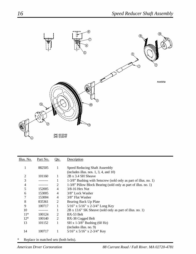
Illus. No. Part No. Qty. Description
1 882505 1 Speed Reducing Shaft Assembly(includes illus. nos. 1, 3, 4, and 10)
2 101160 1 2B x 3.4 SH Sheave3 -------- 1 1-3/8” Bushing with Setscrew (sold only as part of illus. no. 1)4 -------- 2 1-3/8” Pillow Block Bearing (sold only as part of illus. no. 1)5 152005 4 3/8-16 Hex Nut6 153005 4 3/8” Lock Washer7 153004 4 3/8” Flat Washer8 835361 2 Bearing Back Up Plate9 100717 1 5/16” x 5/16” x 2-3/4” Long Key10 -------- 1 2B x 13.6” SK Sheave (sold only as part of illus. no. 1)
11* 100124 2 BX-53 Belt 12* 100140 2 BX-38 Cogged Belt
13 101152 1 SH x 1-3/8” Bushing (60 Hz)(includes illus. no. 9)
14 100717 1 5/16” x 5/16” x 2-3/4” Key
* Replace in matched sets (both belts).
Speed Reducer Shaft Assembly

17
Telephone: (508) 678-9000 Fax: (508) 678-9447
Illus. No. Part No. Qty. Description
1 835297 1 Motor Adjustment Plate2 150501 4 5/16-18 x 3/4” Hex Head Machine Bolt3 153002 8 5/16” Lock Washer4 153001 8 5/16” Flat Washer5 882078 1 3 HP 208-230/380/416/460v 3ø 50/60 Hz Totally Enclosed, Non-Venting
(T.E.N.V.) Motor181019 1 3 HP 575v 3ø 60 Hz Totally Enclosed, Non-Venting (T.E.N.V.) Motor
6 152004 4 5/16” Hex Nut7 101235 1 1-1/8” Pulley
8* 100124 2 BX-53 Cogged Belt 9** -------- 1 5/16” Key
10 150619 2 3/8-16 x 3” Tap Bolt11 152005 4 3/8-16 Hex Nut
* Replace in matched sets (both belts).** Consult factory.
Totally Enclosed, Non-Venting (T.E.N.V.) Drive Motor Assembly

18
American Dryer Corporation 88 Currant Road / Fall River, MA 02720-4781
Direct Spark Ignition (DSI) Burner Assembly

19
Telephone: (508) 678-9000 Fax: (508) 678-9447
Illus. No. Part No. Qty. Description
1 142929 1 1-1/2” to 1” Reducing Coupling2 332117 1 Pipe Bracket3 150309 33 #10-16 x 1/2” Hex Head TEK Crimptite Screw4 142583 1 1” x 40” Nipple5 128919 1* High Voltage (HV) Ignition Cable with Cap 36”6 142808 1 1” x 3” Nipple7 142602 1 1” Union8 152013 2 #6-32 Hex Nut9 142507 1 1” x 90° Street Elbow10 128915 1 Direct Spark Ignition (DSI) Ignitor11 332487 1 Gas Pipe Bracket Straight Extended12 140017 1 1” 24 VAC Redundant Gas Valve (natural gas)
882945 1 1” 24 VAC Gas Valve Liquid Propane (L.P.)13 332486 1 Gas Pipe Bracket Bent Extended14 141240 1 4-Port Manifold ONLY
15* 140839 4 #2 Burner Orifice (natural gas)140820 4 #29 Burner Orifice (liquid propane [L.P.] gas)
16 390169 1 Direct Spark Ignition (DSI) Mount Manifold Rest17 881492 4 Burner Tube ONLY18 332121 1 Burner Tube Support ONLY19 -------- 1 Sail Switch
(refer to Sail Switch Assembly on page 20)20 332113 1 Burner Box Cover Plate21 331290 1 Ignitor/Flame-Probe Sight Hole Disc22 151000 2 #6-32 Pal Nut23 130201 1 330° Manual Reset Hi-Limit24 150005 2 #6-32 x 1/4” Phillips Round Head Machine Screw25 821457 1 Burner Hi-Limit Bracket26 332256 1 Large Dryer Liquid Propane (L.P.) Burner Baffle
(liquid propane [L.P.] models Only)27 801048 1 Johnson Direct Spark Ignition (DSI) Module (3 tries)28 153562 2 #6-32 x 3/4” Clinch Stud29 835037** 1 Burner Assembly (natural gas Only) Complete (less orifice)
821960** 1 Burner Assembly (liquid propane [L.P.] gas Only) Complete (less orifice)820904 1 Burner Box ONLY882118* 1 ML-175 Liquid Propane (L.P.) Conversion Kit
* Consult factory for elevations over 2,000 feet.** Orifices are not included and must be ordered separately.
Direct Spark Ignition (DSI) Burner Assembly

20
American Dryer Corporation 88 Currant Road / Fall River, MA 02720-4781
Illus. No. Part No. Qty. Description
1 105500 1 Sail Switch Actuator Rod2 319202 1 Sail Switch Damper (flat)3 154002 1 1/8” Push On Fastener4 802800 1 Sail Switch Box with Cover and Bracket ONLY
802801 1 Sail Switch Box Assembly Complete(includes illus. nos. 1 through 4 and 6 through 10)For Microprocessor Controller (computer) Models ONLY
882010 1 Sail Switch Box Assembly Complete(includes illus. nos. 1 through 4 and 6 through 10)For Dual Timer Models ONLY
5 150300 2 #10-16 x 1/2” Hex Washer TEK Screw6 150303 2 #4 x 3/4” Pan Head “A” Machine Screw7 122200 1 Sail Switch ONLY
(for microprocessor controller [computer] models Only)122404 1 Sail Switch ONLY
(for dual timer models Only)8 802799 1 Sail Switch Box Cover and Bracket ONLY9 150309 2 #10-16 x 1/2” Hex Head TEK Crimptite Screw10 154004 1 Twin Speed Nut
Sail Switch Assembly

21
Telephone: (508) 678-9000 Fax: (508) 678-9447
Illus. No. Part No. Qty. Description
1 332700 1 Air Jet Tube ONLY2 143287 1 1/4” x 1/8” M.P.T. Male Run Tee3 143259 2 1/4” x 1/8” F.P.T. Bulkhead Fitting4 143100 3 1/4” Aluminum Tube (sold by the foot)5 821081 1 Air Jet Mounting Plate ONLY
(includes illus. nos. 1 through 9)332531 1 Air Jet Mounting Plate ONLY
6 152002 2 1/4-20 Hex Nut7 153007 2 1/4” Lock Washer8 143110 5 1/4” Poly-Flo Tubing (sold by the foot)9 143149 1 1/4” x 1/8” M.P.T. 90° Elbow
Air Jet Assembly

22
American Dryer Corporation 88 Currant Road / Fall River, MA 02720-4781
Microprocessor Reversing Contactor Mounting Panel Assembly
For 208-240 Volt TransformersFor Models Mfd. as of August 29, 2002

23
Telephone: (508) 678-9000 Fax: (508) 678-9447
For 208-240 Volt TransformersFor Models Mfd. as of August 29, 2002
Illus. No. Part No. Qty. Description
1 132439 1 #17-25A Overload2 132465 1 10 HP Contactor3 151001 2 #8-32 Pal Nut4 150009 2 #6-32 x 1-1/2 Phillips Pan Head Machine Screw5 120701 1 4-Position Terminal Block6 132434 1 3 HP “D Line” Reversing Contactor7 822745 1 208-240V Transformer Assembly8 137015 3 Arc Suppressor (A.C.) with 3” Leads9 112068 1 3-Phase (3ø) Power Input Label10 152004 2 5/16-18 Hex Nut11 121502 1 1/2” Wire Standoff12 153002 2 5/16” Lock Washer13 136008 2 Fuse Holder14 136057 2 1/2-Amp 3AG (Slo-Blo) Fuse15 332346 1 Relay Panel16 150301 5 #8-18 x 7/16” Phillips Head TEK Screw17 151000 2 #6-32 Pal Nut18 120765 2 End Stop19 150108 2 #8-32 x 1/2” Phillips Pan Head Machine Screw20 152002 1 1/4-20 Hex Nut21 121010 2 L-70 #14-4 Terminal Lug22 120768 9-7/8” 35 x 15mm Din Rail23 132467 1 9-13A Overload24 112075 1 Ground Label25 153021 1 1/4” Lock Washer26 153525 1 1/4-20 x 1” Self Clinching Stud27 132383 2 Auxiliary Contact Block 2 Normally Opened (N.O.)28 132276 1 Softstart 9A 100-240 VAC Control* 822811 1 Relay Panel Wiring with Softstart* 825267 1 Drive and Blower Motor Contactor Wiring
* Not illustrated.
Microprocessor Reversing Contactor Mounting Panel Assembly

24
American Dryer Corporation 88 Currant Road / Fall River, MA 02720-4781
Microprocessor Reversing Contactor Mounting Panel Assembly
For 208-240 Volt TransformersFor Models Mfd. prior to August 29, 2002

25
Telephone: (508) 678-9000 Fax: (508) 678-9447
Illus. No. Part No. Qty. Description
1 152002 1 1/4-20 Hex Nut2 132465 1 3 HP Contactor - 24 VAC3 151001 2 #8-32 Pal Nut4 150009 2 #6-32 x 1-1/4” Phillips Round Head Machine Screw5 120701 1 4-Position Power Distribution Block6 132497 1 Reversing Contactor - 24 VAC7 822745 1 208-240V Transformer Assembly8 137015 1 Arc Suppressor (A.S.) Board9 153021 1 1/4” Star Washer10 152004 1 5/16-18 Hex Nut11 153002 1 5/16” Lock Washer12 136008 2 Fuse Block/Holder13 136057 2 1/2-Amp (Slo-Blo) Fuse14 332346 1 Contactor/Relay Mounting Panel ONLY15 150301 5 #8-18 x 7/16” Phillips Pan Head TEK Screw16 151000 2 #6-32 Pal Nut17 120765 2 End Stop/Bracket18 150108 2 #8-32 x 1/2” Pan Head Machine Screw19 121010 1 L-70 Ground Lug20 120768 7-3/4” Din Mounting Rail (sold by the inch)21 112075 1 Ground Label22 112068 1 3-Phase (3ø) Power Input Label23 132439 1 Overload-- 825267 1 Contactor Wiring...Not Illustrated-- 829053 1 Relay Panel Wiring...Not Illustrated
Microprocessor Reversing Contactor Mounting Panel AssemblyFor 208-240 Volt TransformersFor Models Mfd. prior to August 29, 2002

26
American Dryer Corporation 88 Currant Road / Fall River, MA 02720-4781
Microprocessor Reversing Contactor Mounting Panel Assembly
For 380-416 Volt TransformersFor Models Mfd. prior to August 29, 2002
27
Telephone: (508) 678-9000 Fax: (508) 678-9447
Microprocessor Reversing Contactor Mounting Panel Assembly
For 380-416 Volt TransformersFor Models Mfd. prior to August 29, 2002
Illus. No. Part No. Qty. Description
1 132467 1 9-13-Amp Overload2 132465 1 10 HP Contactor - 24 VAC3 151001 2 #8-32 Pal Nut4 150009 2 #6-32 x 1-1/2” Phillips Round Head Machine Screw5 120701 1 4-Position Power Distribution Block6 132497 1 “Kline” Reversing Contactor7 801580 1 Transformer (380-416 volt/3ø)8 152004 2 5/16-18 Hex Nut9 121012 1 Ground Lug10 153002 2 5/16” Lock Washer11 136008 1 Fuse Block/Holder12 136057 1 1/2-Amp (Slo-Blo) Fuse13 332346 1 Contactor/Relay Mounting Panel ONLY14 150301 4 #8-18 x 7/16” Phillips Pan Head TEK Screw15 151000 2 #6-32 Pal Nut16 120765 2 End Stop/Bracket17 150108 2 #8-32 x 1/2” Pan Head Machine Screw18 150297 1 #10 x 1/2” Hex Washer TEK Screw19 121010 1 L-70 Ground Lug20 120768 7-3/4” Din Mounting Rail (sold by the inch)-- 830180 1 Relay Panel Wiring...Not Illustrated-- 825267 1 Drive/Blower Motor Contactor Wiring...Not Illustrated
28
American Dryer Corporation 88 Currant Road / Fall River, MA 02720-4781
Microprocessor Reversing Contactor Mounting Panel Assembly
For 460-480 Volt TransformersFor Models Mfd. prior to August 29, 2002

29
Telephone: (508) 678-9000 Fax: (508) 678-9447
Microprocessor Reversing Contactor Mounting Panel Assembly
For 460-480 Volt TransformersFor Models Mfd. prior to August 29, 2002
Illus. No. Part No. Qty. Description
1 132467 1 9-13-Amp Overload2 132465 1 10 HP Contactor - 24 VAC3 151001 2 #8-32 Pal Nut4 150009 2 #6-32 x 1-1/2” Phillips Round Head Machine Screw5 120701 1 4-Position Terminal Block6 132497 1 “Kline” Reversing Contactor7 830193 1 460-480V Transformer Assembly8 152004 2 5/16-18 Hex Nut9 121012 1 Ground Lug10 153002 2 5/16” Lock Washer11 135501 1 2-Pole 1-Amp Circuit Breaker12 137015 1 Arc Suppressor (A.S.)13 332346 1 Relay Panel14 150301 4 #8-18 x 7/16” Phillips Pan Head TEK Screw15 151000 2 #6-32 Pal Nut16 120765 2 End Stop/Bracket17 150108 2 #8-32 x 1/2” Pan Head Machine Screw18 150297 1 #10 x 1/2” Hex Washer TEK Screw19 121010 1 L-70 Ground Lug20 120768 7-3/4” Din Mounting Rail (sold by the inch)-- 830192 1 Relay Panel Wiring...Not Illustrated-- 825267 1 Drive/Blower Motor Contactor Wiring...Not Illustrated

30
American Dryer Corporation 88 Currant Road / Fall River, MA 02720-4781
Steam Damper AssemblyFor Steam Models ONLY
Illus. No. Part No. Qty. Description
1 165017 1 Steam Coil ONLY2 153002 6 5/16” Lock Washer3 152004 6 5/16-18 Hex Nut4 152002 4 1/4-20 Hex Nut5 153007 4 1/4” Lock Washer6 820321 2 Steam Damper Hinge Assembly7 820994 1 Steam Damper Assembly
(includes illus. nos. 7, 10, and 11)8 153007 4 1/4” Lock Washer9 152002 4 1/4-20 Hex Nut10 115995 96 Steam Damper Gasket (sold by the inch)11 102350 2 Steam Damper Foam (68-1/2” length)12 151007 1 7/16-20 Stainless Steel Acorn Nut13 100499 1 1-1/2” Bore x 3” Stroke Piston14 100500 1 Piston Support Bracket15 152002 4 1/4-20 Hex Nut16 153007 4 1/4” Lock Washer17 100472 1 1/4” x 1/8” Connector18 143110 1 1/4” Tubing (sold by the foot)
(refer to Top Console Assembly on page 33)
31
Telephone: (508) 678-9000 Fax: (508) 678-9447
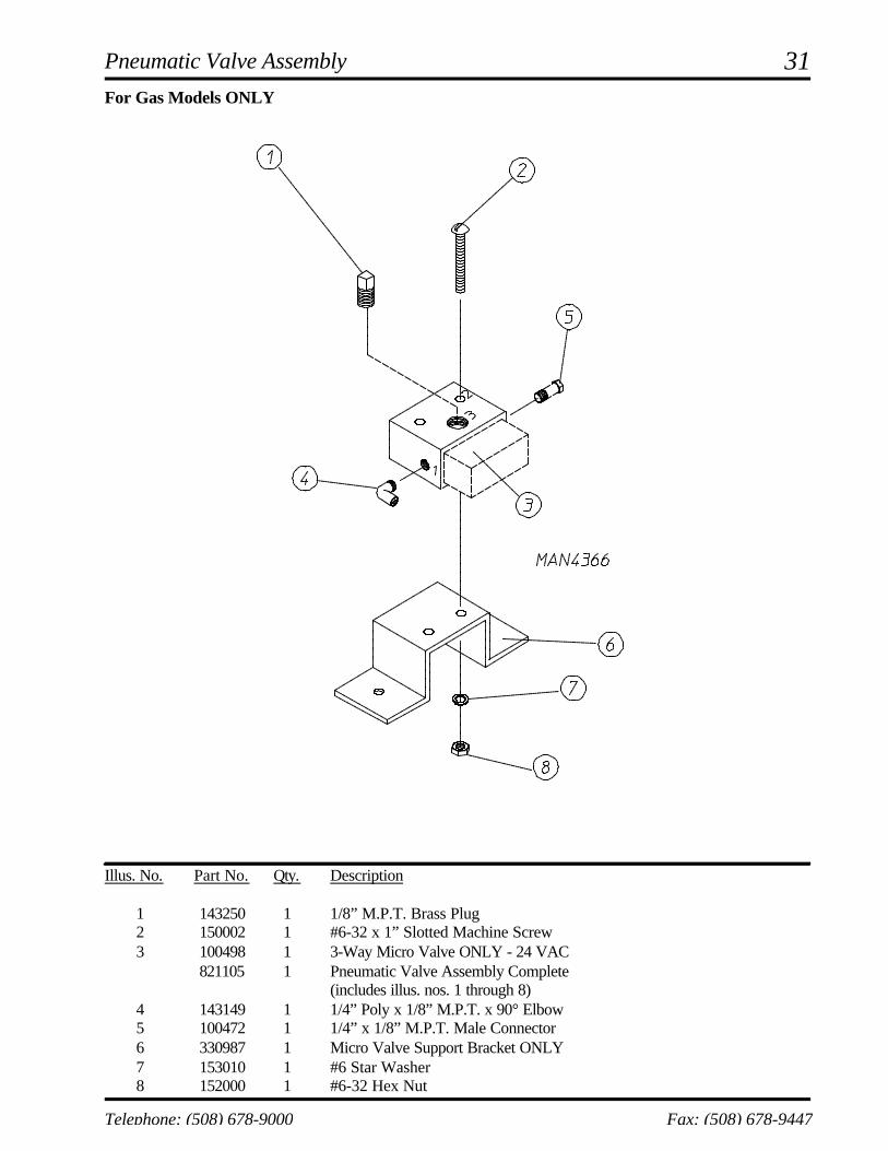
Pneumatic Valve Assembly
For Gas Models ONLY
Illus. No. Part No. Qty. Description
1 143250 1 1/8” M.P.T. Brass Plug2 150002 1 #6-32 x 1” Slotted Machine Screw3 100498 1 3-Way Micro Valve ONLY - 24 VAC
821105 1 Pneumatic Valve Assembly Complete(includes illus. nos. 1 through 8)
4 143149 1 1/4” Poly x 1/8” M.P.T. x 90° Elbow5 100472 1 1/4” x 1/8” M.P.T. Male Connector6 330987 1 Micro Valve Support Bracket ONLY7 153010 1 #6 Star Washer8 152000 1 #6-32 Hex Nut

32
American Dryer Corporation 88 Currant Road / Fall River, MA 02720-4781
Illus. No. Part No. Qty. Description
1 100496 1 1/8” Needle Valve2 143238 3 1/8” Close Nipple3 100498 2 3-Way Micro Valve ONLY - 24 VAC
821104 1 Pneumatic Valve Assembly Complete(includes illus. nos. 1 through 8)
4 143223 1 1/8” F.P.T. Brass Tee5 150002 2 #6-32 x 1” Slotted Machine Screw6 330987 1 Micro Valve Support Bracket ONLY7 153010 2 #6 Star Washer8 152000 2 #6-32 Hex Nut9 100520 2 1/8” N.P.T. Silencer (muffler) ONLY10 100472 2 1/4” x 1/8” Connector
Pneumatic Valve Assembly
For Steam Models ONLY

33
Telephone: (508) 678-9000 Fax: (508) 678-9447
Top Console Assembly
Illus. No. Part No. Qty. Description
1 821085* 1 Top Console Assembly ONLY (for gas models Only)821086* 1 Top Console Assembly ONLY (for steam models Only)
2 112284 1 “Phase 6 OPL Program Location Summary” Label(for microprocessor models Only)
3 --------- 1 Dryer Data Label (not for resale by ADC)4 153007 12 1/4” Lock Washer5 152002 12 1/4-20 Hex Nut6 332323 1 32” Wire Channel7 821105 1 Pneumatic Valve Assembly ONLY (for gas models Only)
(refer to Pneumatic Valve Assembly on page 31)821104 1 Pneumatic Valve Assembly ONLY (for steam models Only)
(refer to Pneumatic Valve Assembly on page 32)8 121104 1 2” x 4” Junction Box ONLY9 121105 1 Junction Box Cover ONLY10 150615 1 1/4-20 x 3/4” Bolt11 153018 4 1/4” Flat Washer12 332186 1 Control Door Hinge Channel13 332132 1 Corner Gusset Brace
* Specify color when ordering.

34
American Dryer Corporation 88 Currant Road / Fall River, MA 02720-4781
FSS Temperature Probe Assembly
Illus. No. Part No. Qty. Description
1 822752 1 Fire Suppression System (FSS) Temperature Probe Assembly(includes illus. nos. 1 through 5)
2 154007 2 Push On Fastener3 390390 1 Sensor Bracket ONLY4 150301 2 #8-18 Phillips Pan Head TEK Screw5 122647 1 Connector ONLY...Not Illustrated
(does not include pins)122700 2 Pins

35
Telephone: (508) 678-9000 Fax: (508) 678-9447
Illus. No. Part No. Qty. Description
1 165114 1 Fire Suppression System (FSS) Solenoid Valve 24V 50/60 Hz2 143220 1 3/8” F.P.T. Brass Tee3 143251 1 3/8” M.P.T. Brass Plug4 143208 2 3/8” Comp x 3/8” M.P.T. Brass Connector5 143099* 6’ 3/8” OD x 0.035 Wall Copper Tubing6 311588 1 Sprinkler Head Mounting Plate7 143303 1 3/8” N.P.T. Brass Locknut8 143155 1 3/8” Brass Elbow 90°9 150430 2 #10 x 1/2” Self Drilling Screw10 150301 2 #8-18 x 7/16” TEK Screw11 143581 1 3 GPM 3/8” F.P.T. Spray Nozzle12 142888 1 1/2” to 3/8” Bushing for Fire Suppression System (FSS) Valve13 824828 1 Arc Suppressor
* Sold by the foot.
FSS Solenoid Assembly
36
American Dryer Corporation 88 Currant Road / Fall River, MA 02720-4781
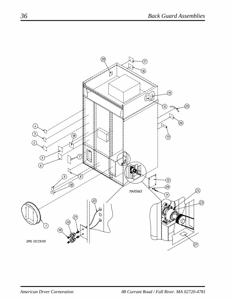
Back Guard Assemblies

37
Telephone: (508) 678-9000 Fax: (508) 678-9447
Back Guard Assemblies
Illus. No. Part No. Qty. Description
1 821793 1 Square Duct to 20” Round Duct Transition Piece Assembly with Damper821956 1 Square Duct to 20” Round Duct Transition Piece Assembly
2 -------- 1 Wiring Diagram for Dryer(contact factory with model and serial number)
3 112046 1 “Computer Ground” Label4 114005 1 “DANGER - Hot” Label5 112519 1 “Routine Maintenance” Label6 114044 1 “High Voltage” Label7 114007 1 “DANGER - High Voltage” Label8 112014 1 “High Voltage” Label9 114008 1 “WARNING - Fumes” Label10 114001 1 “CAUTION - Exhaust/Lint Screen” Label11 150512 4 1/4-20 x 1/2” Hex Head Machine Bolt12 332309 1 Side Access Panel13 112280 1 “Clean Lint Screen” Label14 112017 1 “Address” Label (not for resale)15 -------- 1 “Serial Number” Label (not for resale)16 -------- 1 Wiring Diagram (contact factory with specific dryer serial number)17 112284 1 “Phase 6 Program Location” Label18 114093 1 “Important Manual Reset Hi-Limit” Label19 170511 2 1/8” M.P.T. Zirc (grease) Fitting20 143164 2 1/8” F.P.T. Bulkhead Fitting21 100472 2 1/4” x 1/8” M.P.T. Male Connector22 143115 4 1/4” Nylo-Seal Tube23 100472 2 1/4” x 1/8” M.P.T. Male Connector24 143246 2 1/4-28 x 18” F.P.T. Fitting25 114095 1 “Do Not Dry Mop Heads” Label26 114006 1 “WARNING - Fire Hazard” Label27 114077 1 “Grease Instruction” Label28 114093 1 “Important Manual Reset Hi-Limit” Label29 153007 4 1/4” Lock Washer

ADC 450581 1 - 10/01/02-20


![sticksnsushi.com€¦ · grenache, paradis, domaine preignes le vieux, languedoc 2018 [12.5%] bottle £29 / glass 175 ml £7.20 ultimate provence rosÉ, cótes de provence 2019 [12.5%]](https://img.pdfslide.us/doc/110x75/5fca5430886450116c5ed8e3/grenache-paradis-domaine-preignes-le-vieux-languedoc-2018-125-bottle-29.jpg)