Embed Size (px)
Citation preview
133495-P1Rev A, 06/05
MKS Type VoDM-CVapor on Demand
Module
Designed for Use with Water Only

Copyright © 2005 by MKS Instruments, Inc.
All rights reserved. No part of this work may be reproduced or transmitted in any form or by anymeans, electronic or mechanical, including photocopying and recording, or by any informationstorage or retrieval system, except as may be expressly permitted in writing by MKS Instruments,Inc.
Printed in the United States of America
Baratron® is a registered trademark of MKS Instruments, Inc., Andover, MA
Swagelok® and VCR are registered trademarks of Swagelok Marketing Co., Solon, OH
Inconel® is a registered trademark of Inco Alloys International, Huntington, WV
This manual is for firmware version: 1.00

List of Figures and Tables
iii
Table of Contents
Vapor Flow Controller Safety Information ................................................................................. 1
Symbols Used in This Instruction Manual..................................................................... 1
Symbols Found on the Unit............................................................................................ 2
Safety Procedures and Precautions ................................................................................ 3
Sicherheitshinweise für den Massenflussregler für Dampfförmige Medien ............................... 5
In dieser Betriebsanleitung vorkommende Symbole...................................................... 5
Erklärung der am Gerät angebrachten Symbole............................................................. 6
Sicherheitsvorschriften und Vorsichtsmaßnahmen ........................................................ 7
Informations relatives à la sécurité pour le contrôleur de débit de vapeur.................................. 9
Symboles utilisés dans ce manuel d'utilisation .............................................................. 9
Symboles apparaissant sur l'unité................................................................................... 10
Mesures de sécurité et précautions................................................................................. 11
Medidas de seguridad del controlador de flujo de vapor ............................................................ 13
Símbolos usados en este manual de instrucciones ......................................................... 13
Símbolos hallados en la unidad...................................................................................... 14
Procedimientos y precauciones de seguridad................................................................. 15
Additional Safety Information Relating to the VoDM................................................................ 17
Hazard Warning – “Heavy Object”................................................................................ 17
Hazard Warning – “Hot Surface”................................................................................... 17
Chapter One: General Information............................................................................................. 19
Introduction .................................................................................................................... 19
How This Manual is Organized ..................................................................................... 20
Customer Support........................................................................................................... 20
Chapter Two: Installation........................................................................................................... 21
How To Unpack the Type VoDM Unit.......................................................................... 21
Unpacking Checklist ......................................................................................... 21
Interface Cables.............................................................................................................. 23
Generic Shielded Cable Guidelines................................................................... 23

List of Figures and Tables
iv
Product Location and Requirements ...............................................................................25
Operating Environmental Requirements............................................................25
Safety Conditions...............................................................................................25
Power requirements : .........................................................................................25
Water Supply .....................................................................................................25
Other Considerations .........................................................................................25
Setup ...............................................................................................................................26
Dimensions ........................................................................................................26
Operating Temperature ......................................................................................27
Liquid Source.....................................................................................................27
Outlet Line .........................................................................................................28
Mounting Instructions........................................................................................28
How To Select a New Input Voltage Setting.....................................................30
Connectors ......................................................................................................................31
Analog I/O Connector........................................................................................32
AC Power Connector .........................................................................................34
Start Up ...........................................................................................................................35
Preparation:........................................................................................................35
Warm Up Time ..................................................................................................35
Chapter Three: Overview............................................................................................................37
Safety Considerations .....................................................................................................37
Power Module....................................................................................................37
Main Enclosure ..................................................................................................37
Functional Description....................................................................................................38
Auto Balance Feature......................................................................................................38
LEDs ...............................................................................................................................39
Status LED.........................................................................................................39
Error LED ..........................................................................................................40
Valve Open/Close Feature ..............................................................................................41
Labels..............................................................................................................................42
Serial Number Label ..........................................................................................42
Chapter Four: Operation .............................................................................................................43
General Information........................................................................................................43

List of Figures and Tables
v
How To Set the Flow Set Point...................................................................................... 43
How To Control the Operation of the Valves ................................................................ 44
How To Open the Inlet Valve ........................................................................... 44
How To Close the Inlet Valve........................................................................... 44
How To Open the Outlet Valve ........................................................................ 45
How To Close the Outlet Valve ........................................................................ 45
How To Set the Valve Control to the Flow Set Point ....................................... 45
How To Use the Auto Balance Feature.......................................................................... 46
Chapter Five: Maintenance ........................................................................................................ 47
General Information ....................................................................................................... 47
Storage .............................................................................................................. 47
Cleaning ............................................................................................................ 47
Maintenance-Electrical Work ........................................................................... 47
How to Replace the Fuses .............................................................................................. 48
Appendix A: Standard Operating Procedures for the VoDM-C ................................................. 49
Appendix B: Product Specifications .......................................................................................... 55
Electrical Specifications................................................................................................. 55
Performance Specifications............................................................................................ 55
Physical Specifications................................................................................................... 56
Environmental Specifications ........................................................................................ 56
Appendix C: Model Code Explanation ...................................................................................... 57
Model Code.................................................................................................................... 57
Product Type .................................................................................................................. 57
Full Scale Range and Flow Unit .................................................................................... 57
Fittings ........................................................................................................................... 57
Valve Type..................................................................................................................... 57
Connector ....................................................................................................................... 58
Seals ............................................................................................................................... 58
Index............................................................................................................................................ 59

List of Figures and Tables
vi
List of Figures and Tables
Figures
Figure 1: View of the VoDM module showing the location of the Hazard Warning Labels .....18
Figure 2: View of the VoDM module showing the location of the Center of Gravity ...............18
Figure 3: Preferred Method To Ground an Overall Metal Braided Shielded Cable ...................24
Figure 4: Alternate Method To Ground an Overall Metal Braided Shielded Cable ...................24
Figure 5: Top View of the VoDM Unit ......................................................................................26
Figure 6: Front View of the VoDM Unit ....................................................................................26
Figure 7: Side Views of the VoDM Unit ....................................................................................27
Figure 8: Typical System Configuration.....................................................................................29
Figure 9: Components of the Power Module ..............................................................................30
Figure 10: Front Panel Component Identification ......................................................................31
Figure 11: Location of the LEDs in the Rear of the VoDM Unit ...............................................39
Figure 12: Serial Number Label..................................................................................................42
Tables
Table 1: Definition of Symbols Found on the Unit ........................................................................ 2
Tabelle 2: Bedeutung der am Gerät angebrachten Symbole ........................................................... 6
Tableau 3: Définition des symboles apparaissant sur l'unité ........................................................ 10
Tabla 4: Definición de los símbolos hallados en la unidad........................................................... 14
Table 5: Analog I/O Connector Pinout ......................................................................................... 32
Table 6: System Status LED Indications ...................................................................................... 39
Table 7: Description of the LED Error Codes .............................................................................. 40
Table 8: Valve Control Pins on the Analog I/O Connector ........................................................... 41
Table 9: Fuse Types ...................................................................................................................... 48

Vapor Flow Controller Safety Information
1
Vapor Flow Controller Safety Information
In the event of an emergency, seek safety / medical treatment immediately. Contactyour local MKS Instruments, Inc. Service Center listed on the inside back cover of thismanual or use 1-800-227-8766 to obtain information.
Symbols Used in This Instruction Manual
Definitions of WARNING, CAUTION, and NOTE messages used throughout the manual.
Warning The WARNING sign denotes a hazard to personnel. It callsattention to a procedure, practice, condition, or the like,which, if not correctly performed or adhered to, could result ininjury to personnel.
Caution The CAUTION sign denotes a hazard to equipment. It calls attentionto an operating procedure, practice, or the like, which, if notcorrectly performed or adhered to, could result in damage to ordestruction of all or part of the product.
Note The NOTE sign denotes important information. It calls attention to aprocedure, practice, condition, or the like, which is essential to highlight.

Symbols Found on the Unit Vapor Flow Controller Safety Information
2
Symbols Found on the Unit
The following table describes symbols that may be found on the unit.
Definition of Symbols Found on the Unit
|
On (Supply) IEC 417, No.5007
Off (Supply)IEC 417, No.5008
Earth (ground) IEC 417, No.5017
Protective earth (ground)
IEC 417, No.5019
Frame or chassis IEC 417, No.5020
Equipotentiality IEC 417, No.5021
Direct current IEC 417, No.5031
Alternating currentIEC 417, No.5032
Both direct andalternating currentIEC 417, No.5033-a
Class ll equipment IEC 417, No.5172-a
Three phasealternating current
IEC 617-2 No.020206
Caution, refer toaccompanying
documentsISO 3864, No.B.3.1
Caution, risk ofelectric shock
ISO 3864, No.B.3.6Caution, hot surfaceIEC 417, No.5041
Table 1: Definition of Symbols Found on the Unit

Vapor Flow Controller Safety Information
3
Safety Procedures and Precautions
The following general safety precautions must be observed during all phases of operation of thisinstrument. Failure to comply with these precautions or with specific warnings elsewhere in thismanual violates safety standards of intended use of the instrument and may impair theprotection provided by the equipment. MKS Instruments, Inc. assumes no liability for thecustomer’s failure to comply with these requirements.
DO NOT SUBSTITUTE PARTS OR MODIFY INSTRUMENT
Do not install substitute parts or perform any unauthorized modification to the instrument.Return the instrument to an MKS Calibration and Service Center for service and repair to ensurethat all safety features are maintained.
SERVICE BY QUALIFIED PERSONNEL ONLY
Operating personnel must not attempt component replacement and internal adjustments. Anyservice must be made by qualified service personnel only.
DO NOT OPERATE IN AN EXPLOSIVE ENVIRONMENT
To avoid explosion, do not operate this product in an explosive environment unless it has beenspecifically certified for such operation.
USE PROPER FITTINGS AND TIGHTENING PROCEDURES
All instrument fittings must be consistent with instrument specifications, and compatible with theintended use of the instrument. Assemble and tighten fittings according to manufacturer’sdirections.
CHECK FOR LEAK-TIGHT FITTINGS
Carefully check all vacuum component connections to ensure leak-tight installation.
OPERATE AT SAFE INLET PRESSURES
Never operate at pressures higher than the rated maximum pressure (refer to the productspecifications for the maximum allowable pressure).
INSTALL A SUITABLE BURST DISC
When operating from a pressurized gas source, install a suitable burst disc in the vacuum systemto prevent system explosion should the system pressure rise.
KEEP THE UNIT FREE OF CONTAMINANTS
Do not allow contaminants to enter the unit before or during use. Contamination such as dust,dirt, lint, glass chips, and metal chips may permanently damage the unit or contaminate theprocess.

Safety Procedures and Precautions Vapor Flow Controller Safety Information
4
ALLOW THE UNIT TO WARM UP
If the unit is used to control dangerous gases, they should not be applied before the unit hascompletely warmed up. Use a positive shutoff valve to ensure that no erroneous flow can occurduring warm up.

Sicherheitshinweise für den Massenflussregler fürDampfförmige Medien
5
Sicherheitshinweise für den Massenflussregler fürDampfförmige Medien
In dieser Betriebsanleitung vorkommende Symbole
Bedeutung der mit WARNUNG!, VORSICHT! und HINWEIS gekennzeichneten Absätze indieser Betriebsanleitung.
Warnung! Das Symbol WARNUNG! weist auf eine Gefahr für dasBedienpersonal hin. Es macht auf einen Arbeitsablauf, eineArbeitsweise, einen Zustand oder eine sonstige Gegebenheitaufmerksam, deren unsachgemäße Ausführung bzw.ungenügende Berücksichtigung zu Verletzungen führen kann.
Vorsicht! Das Symbol VORSICHT! weist auf eine Gefahr für das Gerät hin. Esmacht auf einen Bedienungsablauf, eine Arbeitsweise oder einesonstige Gegebenheit aufmerksam, deren unsachgemäße Ausführungbzw. ungenügende Berücksichtigung zu einer Beschädigung oderZerstörung des Gerätes oder von Teilen des Gerätes führen kann.
Hinweis Das Symbol HINWEIS macht auf wichtige Informationen bezüglich einesArbeitsablaufs, einer Arbeitsweise, eines Zustands oder einer sonstigeGegebenheit aufmerksam.

Erklärung der am Gerät angebrachten Symbole Sicherheitshinweise für den Massenflussregler fürDampfförmige Medien
6
Erklärung der am Gerät angebrachten Symbole
Nachstehender Tabelle sind die Bedeutungen der Symbole zu entnehmen, die am Gerätangebracht sein können.
Bedeutung der am Gerät angebrachten Symbole
|Ein (Energie)
IEC 417, No.5007Aus (Energie)
IEC 417, No.5008Erdanschluß
IEC 417, No.5017Schutzleiteranschluß
IEC 417, No.5019
MasseanschlußIEC 417, No.5020
Aquipotential-anschluß
IEC 417, No.5021Gleichstrom
IEC 417, No.5031Wechselstrom
IEC 417, No.5032
Gleich- oderWechselstrom
IEC 417, No.5033-a
Durchgängigedoppelte oder
verstärkte IsolierungIEC 417, No.5172-a
Dreileiter-Wechselstrom(Drehstrom)
IEC 617-2, No.020206
Warnung vor einerGefahrenstelle
(Achtung, Dokumen-tation beachten)
ISO 3864, No.B.3.1
Warnung vorgefährlicher
elektrischer SpannungISO 3864, No.B.3.6
Höhere Temperaturan leicht
zugänglichen TeilenIEC 417, No.5041
Tabelle 2: Bedeutung der am Gerät angebrachten Symbole

Sicherheitshinweise für den Massenflussregler fürDampfförmige Medien
7
Sicherheitsvorschriften und Vorsichtsmaßnahmen
Folgende allgemeine Sicherheitsvorschriften sind während allen Betriebsphasen dieses Geräteszu befolgen. Eine Mißachtung der Sicherheitsvorschriften und sonstiger Warnhinweise in dieserBetriebsanleitung verletzt die für dieses Gerät und seine Bedienung geltendenSicherheitsstandards, und kann die Schutzvorrichtungen an diesem Gerät wirkungslos machen.MKS Instruments, Inc. haftet nicht für Mißachtung dieser Sicherheitsvorschriften seitens desKunden.
Niemals Teile austauschen oder Änderungen am Gerät vornehmen!
Ersetzen Sie keine Teile mit baugleichen oder ähnlichen Teilen, und nehmen Sie keineeigenmächtigen Änderungen am Gerät vor. Schicken Sie das Gerät zwecks Wartung undReparatur an den MKS-Kalibrierungs- und -Kundendienst ein. Nur so wird sichergestellt, daß alleSchutzvorrichtungen voll funktionsfähig bleiben.
Wartung nur durch qualifizierte Fachleute!
Das Auswechseln von Komponenten und das Vornehmen von internen Einstellungen darf nurvon qualifizierten Fachleuten durchgeführt werden, niemals vom Bedienpersonal.
Gerät nicht zusammen mit explosiven Stoffen, Gasen oder Dämpfen benutzen!
Um der Gefahr einer Explosion vorzubeugen, darf dieses Gerät niemals zusammen mit (oder inder Nähe von) explosiven Stoffen aller Art eingesetzt werden, sofern es nicht ausdrücklich fürdiesen Zweck zugelassen ist.

Sicherheitsvorschriften und Vorsichtsmaßnahmen Sicherheitshinweise für den Massenflussregler fürDampfförmige Medien
8
Anweisungen zum Installieren der Armaturen!
Alle Anschlußstücke und Armaturenteile müssen mit der Gerätespezifikation übereinstimmen,und mit dem geplanten Einsatz des Gerätes kompatibel sein. Der Einbau, insbesondere dasAnziehen und Abdichten, muß gemäß den Anweisungen des Herstellers vorgenommen werden.
Verbindungen auf Undichtigkeiten prüfen!
Überprüfen Sie sorgfältig alle Verbindungen der Vakuumkomponenten auf undichte Stellen.
Gerät nur unter zulässigen Anschlußdrücken betreiben!
Betreiben Sie das Gerät niemals unter Drücken, die den maximal zulässigen Druck (sieheProduktspezifikationen) übersteigen.
Geeignete Berstscheibe installieren!
Wenn mit einer unter Druck stehenden Gasquelle gearbeitet wird, sollte eine geeigneteBerstscheibe in das Vakuumsystem installiert werden, um eine Explosionsgefahr aufgrund vonsteigendem Systemdruck zu vermeiden.
Verunreinigungen im Gerät vermeiden!
Stellen Sie sicher, daß Verunreinigungen jeglicher Art weder vor dem Einsatz noch während desBetriebs in das Instrumenteninnere gelangen können. Staub- und Schmutzpartikel, Glassplitteroder Metallspäne können das Gerät dauerhaft beschädigen oder Prozeß und Meßwerteverfälschen.
Geräteeinheit auf Arbeitstemperatur bringen!
Wird das Gerät zur Flußregelung gefährlicher Gase verwendet, so dürfen diese nur nachAbschluß des Anwärmvorgangs zugeführt werden. Um das versehentliche Fließen von Gaswährend der Aufheizperiode zu verhindern, sollte ein Absperrventil (normal geschlossen)eingebaut werden.

Informations relatives à la sécurité pour le contrôleurde débit de vapeur
9
Informations relatives à la sécurité pour le contrôleur dedébit de vapeur
Symboles utilisés dans ce manuel d'utilisation
Définitions des indications AVERTISSEMENT, ATTENTION, et REMARQUE utilisées dans cemanuel.
Avertissement L'indication AVERTISSEMENT signale un danger pour lepersonnel. Elle attire l'attention sur une procédure, unepratique, une condition, ou toute autre situationprésentant un risque d'accident pour le personnel, encas d'exécution incorrecte ou de non respect desconsignes.
Attention L'indication ATTENTION signale un danger pour l'appareil.Elle attire l'attention sur une procédure d'exploitation, unepratique, ou toute autre situation, présentant un risqued'endommagement ou de destruction d'une partie ou de latotalité de l'appareil, en cas d'exécution incorrecte ou de nonrespect des consignes.
Remarque L'indication REMARQUE signale une information importante. Elleattire l'attention sur une procédure, une pratique, une condition, outoute autre situation, présentant un intérêt particulier.

Symboles apparaissant sur l'unité Informations relatives à la sécurité pour le contrôleurde débit de vapeur
10
Symboles apparaissant sur l'unité
Le tableau suivant décrit les symboles pouvant apparaître sur l'unité.
Définition des symboles apparaissant sur l'unité
|Marche
(sous tension)IEC 417, No.5007
Arrêt (hors tension)IEC 417, No.5008
Terre (masse)IEC 417, No.5017
Terre de protection(masse)
IEC 417, No.5019
MasseIEC 417, No.5020
EquipotentialitéIEC 417, No.5021
Courant continuIEC 417, No.5031
Courant alternatifIEC 417, No.5032
Courant continu etalternatif
IEC 417, No.5033-aMatériel de classe IIIEC 417, No.5172-a
Courant alternatiftriphasé
IEC 617-2, No.020206
Attention : se reporterà la documentationISO 3864, No.B.3.1
Attention : risque dechoc électrique
ISO 3864, No.B.3.6
Attention : surfacebrûlante
IEC 417, No.5041
Tableau 3: Définition des symboles apparaissant sur l'unité

Informations relatives à la sécurité pour le contrôleurde débit de vapeur
11
Mesures de sécurité et précautions
Prendre les précautions générales de sécurité suivantes pendant toutes les phases d'exploitationde cet appareil. Le non respect des ces précautions ou des avertissements contenus dans cemanuel constitue une violation des normes de sécurité relatives à l'utilisation de l'appareil etpeut diminuer la protection fournie par l'appareil. MKS Instruments, Inc. n'assume aucuneresponsabilité concernant le non respect des consignes par les clients.
PAS DE SUBSTITUTION DE PIÈCES OU DE MODIFICATION DE L'APPAREIL
Ne pas installer des pièces de substitution ou effectuer des modifications non autorisées surl'appareil. Renvoyer l'appareil à un centre de service et de calibrage MKS pour tout dépannage ouréparation afin de garantir l'intégrité des dispositifs de sécurité.
DÉPANNAGE UNIQUEMENT PAR DU PERSONNEL QUALIFIÉ
Le personnel d'exploitation ne doit pas essayer de remplacer des composants ou de faire desréglages internes. Tout dépannage doit être uniquement effectué par du personnel qualifié.
PAS D'EXPLOITATION DANS UN ENVIRONNEMENT EXPLOSIF
Pour éviter toute explosion, ne pas utiliser cet appareil dans un environnement explosif, sauf encas d'homologation spécifique pour une telle exploitation.
UTILISATION D'ÉQUIPEMENTS APPROPRIÉS ET PROCÉDURES DE SERRAGE
Tous les équipements de l'appareil doivent être cohérents avec ses spécifications, et compatiblesavec l'utilisation prévue de l'appareil. Assembler et serrer les équipements conformément auxdirectives du fabricant.
VÉRIFICATION DE L'ÉTANCHÉITÉ DES CONNEXIONS
Vérifier attentivement toutes les connexions des composants pour le vide afin de garantirl'étanchéité de l'installation.
EXPLOITATION AVEC DES PRESSIONS D'ENTRÉE NON DANGEREUSES
Ne jamais utiliser des pressions supérieures à la pression nominale maximum (se reporter auxspécifications de l'unité pour la pression maximum admissible).
INSTALLATION D'UN DISQUE D'ÉCHAPPEMENT ADAPTÉ
En cas d'exploitation avec une source de gaz pressurisé, installer un disque d'échappement adaptédans le système à vide afin d'éviter une explosion du système en cas d'augmentation de lapression.
Mesures de sécurité et précautions Informations relatives à la sécurité pour le contrôleurde débit de vapeur
12
MAINTIEN DE L'UNITÉ À L'ABRI DES CONTAMINATIONS
Ne pas laisser des produits contaminants pénétrer dans l'unité avant ou pendant l'utilisation. Desproduits contaminants tels que des poussières et des fragments de tissu, de glace et de métalpeuvent endommager l'unité d'une manière permanente ou contaminer le processus.
RESPECT DU TEMPS D'ÉCHAUFFEMENT
Si l'unité est utilisée pour contrôler des gaz dangereux, ceux-ci ne doivent pas être appliquésavant l'échauffement complet de l'unité. Utiliser une valve de fermeture positive afin de garantirqu'aucun flux ne se produise par erreur pendant l'échauffement.

Medidas de seguridad del controlador de flujo devapor
13
Medidas de seguridad del controlador de flujo de vapor
Símbolos usados en este manual de instrucciones
Definiciones de los mensajes de advertencia, precaución y de las notas usados en el manual.
Advertencia El símbolo de advertencia indica la posibilidad de que seproduzcan daños personales. Pone de relieve unprocedimiento, práctica, estado, etc. que en caso de norealizarse u observarse correctamente puede causar dañospersonales.
Precaución El símbolo de precaución indica la posibilidad de producir daños alequipo. Pone de relieve un procedimiento operativo, práctica,estado, etc. que en caso de no realizarse u observarsecorrectamente puede causar daños o la destrucción total o parcialdel equipo.
Nota El símbolo de notas indica información de importancia. Este símbolopone de relieve un procedimiento, práctica o condición cuyoconocimiento es esencial destacar.

Símbolos hallados en la unidad Medidas de seguridad del controlador de flujo devapor
14
Símbolos hallados en la unidad
La tabla siguiente contiene los símbolos que puede hallar en la unidad.
Definición de los símbolos hallados en la unidad
|Encendido
(alimentación eléctrica)IEC 417, N° 5007
Apagado(alimentación eléctrica)
IEC 417, N° 5008Puesta a tierra
IEC 417, N° 5017Protección a tierraIEC 417, N° 5019
Caja o chasisIEC 417, N° 5020
EquipotencialidadIEC 417, N° 5021
Corriente continuaIEC 417, N° 5031
Corriente alternaIEC 417, N° 5032
Corriente continua yalterna
IEC 417, N° 5033-aEquipo de clase II
IEC 417, N° 5172-a
Corriente alternatrifásica
IEC 617-2, N° 020206
Precaución. Consultelos documentos
adjuntosISO 3864, N° B.3.1
Precaución. Riesgode descarga eléctricaISO 3864, N° B.3.6
Precaución.Superficiecaliente
IEC 417, N° 5041
Tabla 4: Definición de los símbolos hallados en la unidad

Medidas de seguridad del controlador de flujo devapor
15
Procedimientos y precauciones de seguridad
Las precauciones generales de seguridad descritas a continuación deben observarse durantetodas las etapas de funcionamiento del instrumento. La falta de cumplimiento de dichasprecauciones o de las advertencias específicas a las que se hace referencia en el manual,constituye una violación de las normas de seguridad establecidas para el uso previsto delinstrumento y podría anular la protección proporcionada por el equipo. Si el cliente no cumpledichas precauciones y advertencias, MKS Instruments, Inc. no asume responsabilidad legalalguna.
NO UTILICE PIEZAS NO ORIGINALES O MODIFIQUE EL INSTRUMENTO
No instale piezas que no sean originales o modifique el instrumento sin autorización. Paraasegurar el correcto funcionamiento de todos los dispositivos de seguridad, envíe el instrumentoal Centro de servicio y calibración de MKS toda vez que sea necesario repararlo o efectuar tareasde mantenimiento.
LAS REPARACIONES DEBEN SER EFECTUADAS ÚNICAMENTE POR TÉCNICOSAUTORIZADOS
Los operarios no deben intentar reemplazar los componentes o realizar tareas de ajuste en elinterior del instrumento. Las tareas de mantenimiento o reparación deben ser realizadasúnicamente por personal autorizado.
NO HAGA FUNCIONAR ESTE INSTRUMENTO EN UN AMBIENTE CON RIESGO DEEXPLOSIONES
Para evitar que se produzcan explosiones, no haga funcionar este producto en un ambiente conriesgo de explosiones, excepto cuando el mismo haya sido certificado específicamente para taluso.
USE ACCESORIOS ADECUADOS Y REALICE CORRECTAMENTE LOSPROCEDIMIENTOS DE AJUSTE
Todos los accesorios del instrumento deben cumplir las especificaciones del mismo y sercompatibles con el uso que se debe dar al instrumento. Arme y ajuste los accesorios de acuerdocon las instrucciones del fabricante.
COMPRUEBE QUE LAS CONEXIONES SEAN A PRUEBA DE FUGAS
Inspeccione cuidadosamente las conexiones de los componentes de vacío para comprobar quehayan sido instalados a prueba de fugas.
HAGA FUNCIONAR EL INSTRUMENTO CON PRESIONES DE ENTRADA SEGURAS
No haga funcionar nunca el instrumento con presiones superiores a la máxima presión nominal(en las especificaciones del instrumento hallará la presión máxima permitida).

Procedimientos y precauciones de seguridad
16
INSTALE UNA CÁPSULA DE SEGURIDAD ADECUADA
Cuando el instrumento funcione con una fuente de gas presurizado, instale una cápsula deseguridad adecuada en el sistema de vacío para evitar que se produzcan explosiones cuando subala presión del sistema.
MANTENGA LA UNIDAD LIBRE DE CONTAMINANTES
No permita el ingreso de contaminantes en la unidad antes o durante su uso. Los productoscontaminantes tales como polvo, suciedad, pelusa, lascas de vidrio o virutas de metal puedendañar irreparablemente la unidad o contaminar el proceso.
PERMITA QUE LA UNIDAD SE CALIENTE
Si se utiliza la unidad para controlar gases peligrosos, no libere los gases hasta que la unidadtermine de calentarse. Use una válvula de cierre positivo para impedir todo flujo no deseadodurante el período de calentamiento.

Additional Safety Information Relating to the VoDM
17
Additional Safety Information Relating to the VoDM
Hazard Warning – “Heavy Object”
Located on the enclosure of the VoDM is the following symbol:
This symbol indicates that the VoDM is considered a “Heavy Object” and requires a two-personlift. Please take caution in lifting the device and have appropriate assistance when doing so. Inaddition, the NIOSH Lifting Formula should be used in a Manual Handling Worksheet toevaluate the final installation location in a host tool. This should be used to determine if theVoDM could exceed the two-person lift limitations and require a lift assist in order to position orremove it. Please note that the center of gravity location is displayed in Figure 2 below.
Hazard Warning – “Hot Surface”
Located on the enclosure of the VODM is the following symbol:
During operation the outlet port as well as any heated interconnecting lines, may be attemperatures at or exceeding 100°C. Please use caution and appropriate tools when handling thedevice, as there is a risk of burn. Always assume the outlet port is HOT.
The location of the Hazard Labels on the VoDM is shown in Figure

Hazard Warning – “Hot Surface” Additional Safety Information Relating to the VoDM
18
Figure 1: View of the VoDM module showing the location of the Hazard Warning Labels
Figure 2: View of the VoDM module showing the location of the Center of Gravity

Chapter One: General Information Introduction
19
Chapter One: General Information
Introduction
The Type VoDM-C Vapor on Demand Module (VoDM) is designed to vaporize water andcontrol the flow of water vapor without the need for a carrier gas. The VoDM unit is available intwo models:• The VoDMC52CR1BE model can deliver water vapor in a flow rate from 50 standard cubic
centimeters per minute (sccm) to 500 sccm.
• The VoDMC13CR1BE model can deliver water vapor in a flow rate from 100 standard cubiccentimeters per minute (sccm) to 1 standard liter per minute (slm).
• The VoDMC33CR1BE model can deliver water vapor in a flow rate from 300 standard cubiccentimeters per minute (sccm) to 3 standard liters per minute (slm).
The VoDM system consists of three mini-Baratron® absolute pressure transducers, a flow nozzle,two high temperature solenoid valves, and a heater block system capable of maintainingtemperatures from 30° to 150° C. Connections at the inlet and outlet are made with Swagelok ®VCR® fittings. The VoDM has a normally closed proportional control valve on both the inlet andoutlet lines. These valves are not positive shutoff valves; some leakage across the valve mayoccur. If your system cannot tolerate leakage across the valve, install a separate, positive shutoffvalve.
The system includes an auto balance feature, which compensates for subtle shifts in the zeroreading of the two transducers over time. The auto balance feature removes the difference inreading between the transducers, without the need to pump the system down to base pressure andre-zero each transducer separately.
The VoDM includes a status LED that indicates whether the unit is operating normally or hasencountered a fault condition.

How This Manual is Organized Chapter One: General Information
20
How This Manual is Organized
This manual provides instructions on how to set up, install, and operate a Type VoDM unit.
Before installing the Type VoDM unit in a system or operating it, familiarize yourself withall precautionary notes in the Safety Messages and Procedures section at the front of thismanual. Observe and obey all WARNING and CAUTION notes in the manual.
Chapter One, General Information, (this chapter) introduces the product and describes theorganization of the manual.
Chapter Two, Installation, explains the VoDM’s environmental requirements and describes howto mount the instrument in your system.
Chapter Three, Overview, gives a brief description of the instrument and its functionality.
Chapter Four, Operation, describes how to use the instrument and explains all the functions andfeatures.
Chapter Five, Maintenance, lists maintenance required to keep the instrument in good workingcondition.
Appendix A, Product Specifications, lists the specifications of the instrument.
Appendix B, Model Code Explanation, explains the model code used to order the instrument.
Customer Support
Standard maintenance and repair services are available at all regional MKS Calibration andService Centers. In addition, MKS accepts the instruments of other manufacturers forrecalibration using the Primary and Transfer Standard calibration equipment located at all of ourregional service centers. Should any difficulties arise in the use of your Type VoDM instrument,or to obtain information about companion products MKS offers, contact any authorized MKSCalibration and Service Center. If it is necessary to return the instrument to MKS, please obtain aReturn Material Authorization (RMA) Number from the MKS Calibration and Service Centerbefore shipping. The RMA Number expedites handling and ensures proper servicing of yourinstrument. For disposal instructions at end of life please contact your local MKS service center.
The inside back cover of this manual lists MKS Calibration and Service Centers.
Warning All returns to MKS Instruments must be free of harmful,corrosive, radioactive, and toxic materials.

Chapter Two: Installation How To Unpack the Type VoDM Unit
21
Chapter Two: Installation
How To Unpack the Type VoDM Unit
MKS has carefully packed the Type VoDM unit so that it reaches you in perfect operating order.However, on receipt of the unit, you should check for defects, cracks, broken connectors, etc., tobe certain that the VoDM was not damaged during shipment.
Warning MKS Type VoDM is considered a Heavy Object. Any lifting or movingof the unit should be performed by two people
Warning During usage the outlet port, internal heaters and flow path and anyheated attached plumbing may reach temperatures at or above 100°C.Please use caution when handling
Note Do not discard any packing materials until you have completed yourinspection and are sure the unit arrived safely.
If you find any damage, notify your carrier and MKS immediately. If it is necessary to return theunit to MKS, obtain a Return Material Authorization (RMA) Number from the MKS ServiceCenter before shipping. The inside back cover of this manual lists MKS Calibration and ServiceCenters.
Caution Only qualified individuals should perform the installation and anyuser adjustments. They must comply with all the necessary ESD andhandling precautions while installing and adjusting the instrument.Proper handling is essential when working with highly sensitiveprecision electronic instruments.
Unpacking ChecklistStandard Equipment:
• Type VoDM Unit
• Type VoDM Instruction Manual (this book)
Optional Equipment:
• Electrical Connector Accessories Kit: VoDMA-K1Includes a mate for the electrical connector
• VoDM Power Supply 15 Foot Extension Cable: CB VoDM-2-15

Chapter Two: Installation
22
• D.I. Water Bleed / Recirculation Manifold: 124679-G1
Caution The VoDM is shipped to you leak tight. In the event of physicaltrauma to the unit and/or it’s packaging during shipment,installation, or use be sure to recheck seal to ensure continuousvacuum integrity. The VoDM can be mounted in 2 orientations.Should the seal integrity become compromised due to overstress asmall amount of water may exit the enclosure. In the Horizontalorientation, water may leak from around base. In the Verticalorientation, flow up, water may leak from the base near the inletport. Consider this information when assessing the final installationlocation.

Chapter Two: Installation Interface Cables
23
Interface Cables
Follow these guidelines when making the cable to connect the VoDM unit to your system.
Generic Shielded Cable Guidelines
If you choose to manufacture your own cables, follow the guidelines below:• The cable must have a braided metal shield, covering all wires. Aluminum foil and spiral
shielding are not as effective; using either may compromise regulatory compliance.
• The connectors must have a metal case that is in direct contact with the cable’s shield on thewhole circumference of the cable. The inductance of a flying lead or wire from the shield tothe connector will seriously degrade the shield’s effectiveness. The shield should be groundedto the connector before its internal wires exit.
• With very few exceptions, connectors must make good ground contact to the device’s case. A10-32 threaded insert is provided for this purpose, next to the I/O port (see Figure 7, page 27);connection to it using 12 AWG wire is necessary to achieve CEM Class B limits. “Goodcontact” is about 0.01 ohms. The ground should surround all wires. Contact to ground at justone point may not suffice.
• It is important that shielded cables with flying leads at one or both ends have the shieldgrounded at each such end, before the wires exit. Make this ground with absolute minimumlength. (A ¼ inch piece of #22 wire may be undesirably long since it has approximately 5 nHof inductance, equivalent to 31 ohms at 1000 MHz). After picking up the braid’s ground,keep wires and braid flat against the case. Grounded metal covers are not usually requiredover terminal strips; if one is required, that is stated in the Declaration of Conformity or in theinstruction manual.
• In selecting the appropriate type and wire size for cables, consider:
The voltage ratings
The cumulative I2R heating of all the conductors (keep them safely cool)
The IR drop of the conductors, so that adequate power or signal voltage gets to thedevice
The capacitance and inductance of cables that handle fast signals, such as data linesor stepper motor drive cables
Some cables may need internal shielding from specific wires to others; see theinstruction manual for details regarding this matter

Interface Cables Chapter Two: Installation
24
Example 1: Preferred Method To Ground Cable(shown on a transducer)
External Tooth Lock
Transducer
Overall Insulation(if present)
Bare Metal CableMaking Firm ContactTo Braid
Braid Here Is Desirable;(not usually necessary)
Keep Wires andFlat Against Case
Metal Cable ClampScrewSplit Lock
Transducer
Optional Plastic or MetalClamp (For Physical Strain
Figure 3: Preferred Method To Ground an Overall Metal Braided Shielded Cable
Example 2: Alternate Method To Ground Cable(shown on a transducer)
External Tooth Lock Wash
Transducer
Overall Insulation(if present)
Braid Strands TwistedUnder Washer
Keep Wires FlatAgainst Case
Optional Plastic or Metal CableClamp (For Physical Strain Relief)
ScrewSplit Lock Washer
Flat Washers
Transducer Housing
Figure 4: Alternate Method To Ground an Overall Metal Braided Shielded CableUse this method when cable clamp is not available

Chapter Two: Installation Product Location and Requirements
25
Product Location and Requirements
Operating Environmental Requirements• Ambient Temperature Range:15° to 45° C (59° to 113° F)
• Connect the power cord to a grounded outlet.
• Ventilation requirements include sufficient air circulation.
Safety ConditionsThe VoDM unit poses no safety risk under the following environmental conditions.• Altitude: up to 2000 m
Power requirements :• Power supply: 110 VAC @ 4 Amp; 220VAC @ 1.6 Amp
Supplies power to the Controller and the heaters with a selection of four fine voltagepower input settings, marked 100, 120, 220, and 240 at the input connector. Refer to HowTo Select a New Input Voltage Setting, page 30.
Water Supply• Water supplied to the VoDM for vaporization must be pressurized to 20~40 psig, de-ionized,
and filtered to one micron or less. See Liquid Source, page 27.
Caution Do not allow liquid line pressure to drop below 20 psig, or the liquidwater may vaporize too early. Vaporization must not occur before theliquid reaches the inlet of the VoDM unit.
Other Considerations• Do not mount the VoDM unit in an upside down position, since particulates and condensation
may accumulate on the transducer sensing diaphragms and alter the pressure readings. Referto Mounting Instructions, page 28, for more information.
• If your system cannot tolerate some leakage across the control valve, install a separatepositive shutoff valve. The normally closed, proportional control valve in the VoDM systemis not a positive shutoff valve; some leakage across the valve may occur.
• The VoDM unit is bag packaged in a clean room environment; keep it bagged untilinstallation. It is important to protect the unit’s Swagelok VCR fittings since damaged sealsurfaces may leak.

Setup Chapter Two: Installation
26
Setup
Dimensions
Note All dimensions are listed in inches with millimeters in parentheses.
4.005.46(139) (101.6)
5.00
Ø 0.35(8.9) X 4
10.93
12.00 0.50(12.7)(304.8)
(127)
(277.6)
(12.7)
0.50
Figure 5: Top View of the VoDM Unit
HIGH VOLTAGE, CAN CAUSE SEVERE INJURY OR DEATH.DISCONNECT POWER CORD BEFORE REMOVING COVER.SEE INSTRUCTION MANUAL FOR ADDITIONAL SAFETY PROCEDURESAND CAUTIONS.
!
(212.5)
(311)
(346)13.63
8.37
13.0 (330.2)
12.25
Setting
Fuses 250V IEC
~Line48-62 Hz
330VA Max
100 120 220 240
90-105V 100-130 V 200-240 V 210-250 V
4.0 A (T) 4.0 A (T) 2.0 A (T) 2.0 A (T)
12.99 (330)Face to Face
Figure 6: Front View of the VoDM Unit
Anchor point
Anchor point

Chapter Two: Installation Setup
27
(76.2)3.00
2.73(69.3)
(49.8)1.96
+
Case Ground
Thermal SwitchReset Access
Figure 7: Side Views of the VoDM Unit
Operating TemperatureThe system operating temperature must be high enough to prevent condensation of the vaporizedwater. The operating temperature of the vaporizer is factory set at 140° C and the flow controlbody where steam is stored and flow is controlled is factory set at 125°C.
Note Should an abnormal operating condition occur which produces a temperature spike 210°C, the bimetalic thermal switch will snap into an open position cutting of
power to all heaters. If the situation is a transient phenomenon, the switch can bereset by poking through the access port with a suitable blunt object (1/8" pin) tooperate the white plunger, turning the heaters back on. If it is not transient in natureand the problem reoccurs, remove power and seek factory assistance.
Liquid SourceThe liquid water source must:
• Be de-ionized
• Be pressurized to 30 psig ±10 psig
• Be filtered to one micronThe filtration prevents clogging of orifices.
• Have very low Total Dissolved Solids (TDS), with:
A volume conductivity of not more than 1, and preferably 0.1 micromho/cm

Setup Chapter Two: Installation
28
Or
A volume resistivity of not less than 2, and preferably greater than 18 MOhmcm
It is not necessary to heat the water before it enters the VoDM unit.
Caution Do not open the inlet valve manually while the liquid water source isattached, since the system may flood.
Outlet LineThe outlet line must be heated to sufficient temperature to maintain the vapor phase and preventcondensation.
Mounting InstructionsThe VoDM unit can be mounted in two orientations:
• Horizontally, with the base down. This is the preferred orientation.
• Vertically, with the flow UP.
Do not mount the unit upside down (with the base plate on top), or on its side.
Warning Read and follow all messages in Vapor Flow Controller SafetyInformation, page 1, BEFORE attempting to install the VoDMunit. Failure to adhere to these messages could result ininjury to personnel.
Caution Ensure that the VoDM controller is not mounted in an upside downposition, since particulates and condensation may accumulate on thetransducer sensing diaphragm and alter the pressure readings.
Refer to Figure 8: Typical System Configuration, page 29, for a typical system configuration.
To mount the VoDM unit:
1. Ensure that all valves between the unit and the water source are closed.
2. Verify that the inlet fitting is connected to the water source, and the output fitting to thedownstream side.The front panel of the VoDM unit has an arrow indicating the direction of flow. (Refer toFigure 6: Front View of the VoDM Unit, page 26.) The inlet is a 4-VCR male fitting; theoutlet is an 8-VCR male fitting.
3. Allow adequate space for the connectors.Straight, shielded connectors require approximately 3” (76.2 mm). Right angleconnectors require approximately 2” (50.8 mm).

Chapter Two: Installation Setup
29
4. Place the VoDM unit so the flow is in the direction of the arrow on the side of thecontroller.
5. Secure the VoDM unit in place.The base plate of the unit has four clearance holes (0.35 inch diameter) to accommodatemounting screws. Refer to Figure 5: Top View of the VoDM Unit, page 26, for thelocation of the mounting holes.
Heated DeliveryLine
Process
Liquid WaterSource
Positive ShutoffValve
Filter
HIGH VOLTAGE, CAN CAUSE SEVERE INJURYOR DEATH.
DISCONNECT POWER CORD BEFORE REMOVING
!
Positive ShutoffValve (Optional)
Figure 8: Typical System Configuration
Caution If your system cannot tolerate some leakage across the control valve,install a separate positive shutoff valve. The normally closed,proportional control valve in the VoDM system is not a positiveshutoff valve; some leakage across the valve may occur.
Note The outlet line must be heated to 100° C to prevent condensation of thewater vapor. The inlet line does not have to be heated.
Setup Chapter Two: Installation
30
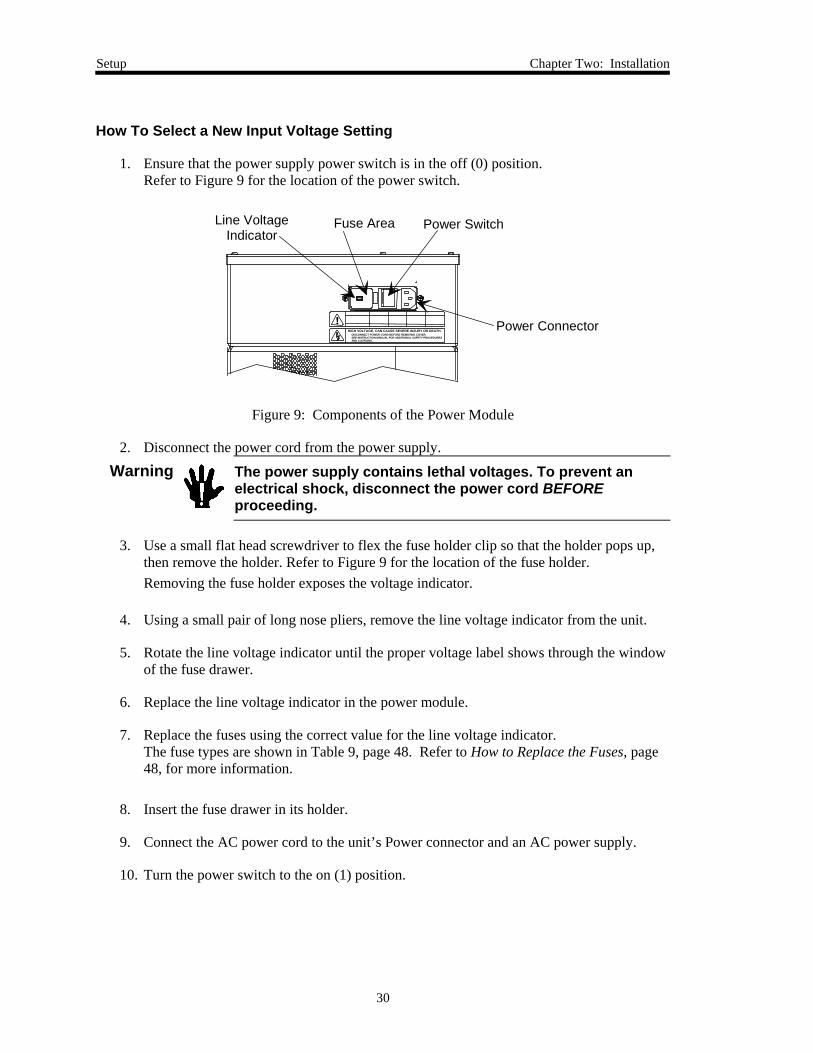
How To Select a New Input Voltage Setting
1. Ensure that the power supply power switch is in the off (0) position.Refer to Figure 9 for the location of the power switch.
Power Connector
Power SwitchFuse AreaLine VoltageIndicator
120
HIGH VOLTAGE, CAN CAUSE SEVERE INJURY OR DEATH.DISCONNECT POWER CORD BEFORE REMOVING COVER.SEE INSTRUCTION MANUAL FOR ADDITIONAL SAFETY PROCEDURESAND CAUTIONS.
!
Figure 9: Components of the Power Module
2. Disconnect the power cord from the power supply.
Warning The power supply contains lethal voltages. To prevent anelectrical shock, disconnect the power cord BEFOREproceeding.
3. Use a small flat head screwdriver to flex the fuse holder clip so that the holder pops up,then remove the holder. Refer to Figure 9 for the location of the fuse holder.Removing the fuse holder exposes the voltage indicator.
4. Using a small pair of long nose pliers, remove the line voltage indicator from the unit.
5. Rotate the line voltage indicator until the proper voltage label shows through the windowof the fuse drawer.
6. Replace the line voltage indicator in the power module.
7. Replace the fuses using the correct value for the line voltage indicator.The fuse types are shown in Table 9, page 48. Refer to How to Replace the Fuses, page48, for more information.
8. Insert the fuse drawer in its holder.
9. Connect the AC power cord to the unit’s Power connector and an AC power supply.
10. Turn the power switch to the on (1) position.

Chapter Two: Installation Connectors
31
Connectors
There are two connectors located on the VoDM unit: an Analog I/O and an AC Power connector(refer to Figure 10). The pinout of the Analog I/O connector is listed on the inlet-side panel, asshown in Figure 7, page 27. The pinout for this connector is also listed in Table 5, page 32.
Power Entry Module
Line Cord ConnectorAnalog I/OConnector
Outlet FittingInlet
Fitting
Fuse HolderLine Voltage Selector
HIGH VOLTAGE, CAN CAUSE SEVERE INJURYOR DEATH.
DISCONNECT POWER CORD BEFORE REMOVING
!
Figure 10: Front Panel Component Identification

Connectors Chapter Two: Installation
32
Analog I/O ConnectorThe 15-pin male Type “D” Analog I/O connector provides the pressure output, set point input,and valve control signals.
Analog I/O Connector Pinout
Pin Number Assignment
1 Manual Valve Control*
2 Flow Output
3 Inlet Valve*
4 Outlet Valve*
5 Analog Ground
6 No Connection
7 No Connection
8 Flow Set Point (0 to 5 VDC)
9 Exhaust Pressure Output
10 Error Output
11 Analog ground
12 Analog ground
13 System at Temperature
14 Auto Balance
15 No Connection
* Refer to Valve Open/Close Feature, page41, for more information
Table 5: Analog I/O Connector Pinout
Chapter Two: Installation Connectors
33
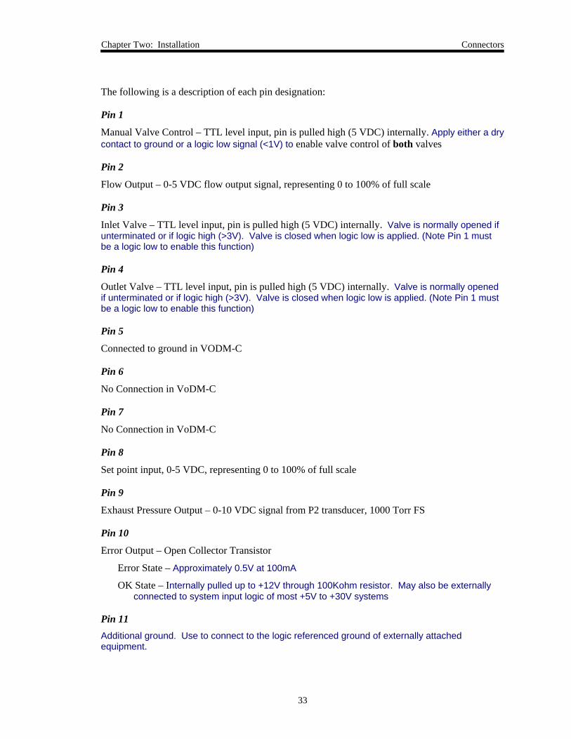
The following is a description of each pin designation:
Pin 1
Manual Valve Control – TTL level input, pin is pulled high (5 VDC) internally. Apply either a drycontact to ground or a logic low signal (<1V) to enable valve control of both valves
Pin 2
Flow Output – 0-5 VDC flow output signal, representing 0 to 100% of full scale
Pin 3
Inlet Valve – TTL level input, pin is pulled high (5 VDC) internally. Valve is normally opened ifunterminated or if logic high (>3V). Valve is closed when logic low is applied. (Note Pin 1 mustbe a logic low to enable this function)
Pin 4
Outlet Valve – TTL level input, pin is pulled high (5 VDC) internally. Valve is normally openedif unterminated or if logic high (>3V). Valve is closed when logic low is applied. (Note Pin 1 mustbe a logic low to enable this function)
Pin 5
Connected to ground in VODM-C
Pin 6
No Connection in VoDM-C
Pin 7
No Connection in VoDM-C
Pin 8
Set point input, 0-5 VDC, representing 0 to 100% of full scale
Pin 9
Exhaust Pressure Output – 0-10 VDC signal from P2 transducer, 1000 Torr FS
Pin 10
Error Output – Open Collector Transistor
Error State – Approximately 0.5V at 100mA
OK State – Internally pulled up to +12V through 100Kohm resistor. May also be externallyconnected to system input logic of most +5V to +30V systems
Pin 11Additional ground. Use to connect to the logic referenced ground of externally attachedequipment.

Connectors Chapter Two: Installation
34
Pin 12
Additional ground. Use to connect to the logic referenced ground of externally attachedequipment.
Pin 13
The signal from an open collector transistor indicates when the VoDM system is at temperature.The open collector uses logic high; the signal is low when the system is at temperature and highwhen the system is not at temperature.
The ratings for the open collector are:Current Output Low: Internally pulled up to +12V through 100Kohm resistor. May alsobe externally connected to system input logic of most +5V to +30V systems
Voltage Output High: Approximately 0.5V at 100mA
Pin 14
Auto Balance – TTL level input, pin is pulled high (5 VDC) internally. Apply either a dry contactto ground or a logic low signal (<1V) to activate Auto Balance.
Pin 15
No Connection to ground in VoDM-C
AC Power ConnectorThe Power Entry module, located on the front panel of the VoDM unit, contains:
• Line voltage selector
• IEC power line connector
• Power line fuses (2)
• RFI power line filter
Refer to Figure 10, page 31, for the location of each component.

Chapter Two: Installation Start Up
35
Start Up
Warning Read and follow all safety messages listed in Vapor FlowController Safety Information, page 1, BEFORE attempting tooperate the VoDM unit. Failure to adhere to these messagescould result in personal injury.
Preparation:
1. Connect all liquid and gas lines and electrical cables.
Caution Water should not be present in the liquid lines at this point.
2. Manually open the inlet and outlet valves. Refer to How To Control the Operation of theValves, page 44, for details.
3. Leak check the entire system.
4. Allow the system to warm up for three (3) hours.Warming the unit with the valves open drives off residuals adsorbed on internal surfaces.
Caution Monitor the VoDM unit during the warm up process. Should theunit encounter an EPROM failure, the heaters may still turn on andcause the unit to overheat. A mechanical thermal safety switch shutsoff power when the unit’s temperature exceeds 210° C.
Warm Up TimeThe unit requires three (3) hours to warm up. Although the indicated temperature may stabilize atthe desired operational temperature within 1 to 2 hours, a full 3 hours is required for the entireunit to stabilize.
During the warm up period the temperature of the VoDM unit may overshoot the set pointtemperature by a few degrees.
Note MKS recommends that the instrument be powered at all times.Continuously powering the unit avoids long warmups and reducesthermal stress on sensitive components resulting from temperaturecycling. However, if the unit is unused for more than 48 hours, it shouldbe shut down and purged. See General Information, page 43.

Chapter Three: Overview Safety Considerations
37
Chapter Three: Overview
Safety Considerations
The design philosophy for the VoDM unit is to develop a safe product suitable for semiconductorproduction equipment. The goal is to ease integration of the device without adding cost orcomplexity, or compromising safety. Original equipment manufacturers (OEMs) should find iteasy to add a VoDM unit to a process tool and comply with the various regulatory agencies andspecifications in the semiconductor manufacturing field.
The VoDM unit consists of a Power Module and a Main Enclosure.
Power ModuleThe Power Module is a separate enclosure that handles incoming AC power and delivers 24 VoltsAC to the heaters in the Main Enclosure of the VoDM unit. The power inlet is a standard IEC 320type double pole switch connector module, with integral fusing. Inside the power distributionbox, the inlet fixture is insulated with a boot to prevent human contact. Power goes to an isolationtransformer that reduces the voltage to 24 Volts AC. All wiring is routed through a DIN railcontact block designed to meet safety standards that include preventing human contact. Thewiring is routed to the Main Enclosure of the VoDM unit through a high power connector at theinterface between the enclosures. The Power Module and Main Enclosure are fastened togetherwith four bolts, which are not externally accessible. Removing the Power Module from the MainEnclosure disconnects power to the Main Enclosure. An optional 15-foot cable with matingconnectors is available for remote placement of the power supply.
Main EnclosureThe Main Enclosure holds the control circuits and mechanisms to control and produce watervapor from liquid. An internal frame holds the circuit boards and solid-state relays. Immersion-type resistance heaters are imbedded in the walls of the flow body. These heaters are controlled intwo circuits; each circuit is monitored by an RTD device and has a thermal snap switch in serieswith the heater elements. The control software only allows the VoDM unit to operate when thetemperature is between 120° and 160°C. If the temperature in either circuit rises to between 160°and 200°C, the VoDM reports an over temperature error. If the temperature exceeds 210°C, thethermal snap switch opens the circuit. The 210°C threshold is within specifications for thematerials and seals used in the vacuum vessel.
Only 24 Volts AC/DC and lower potentials are present in the Main Enclosure, and a short-circuitcurrent greater than 4 Amps at 115 VAC, or 1.6 Amps at 220 VAC will blow the Power Supplyfuse. This feature prevents damage or injury in case of a water leak. Open areas on each end ofthe Main Enclosure prevent accumulation of water inside the unit. If the CPU circuitmalfunctions (CPU not functioning system shutdown), the failsafe “watchdog” timer expires andautomatically attempts to restart the system. The restart sequence includes shutting off the heatersand closing the valves. The heating element remains in the condition it was in before systemshutdown.

Functional Description Chapter Three: Overview
38
Functional Description
Operation of the VoDM system is based on flow equations for a compressible gas across anorifice. Two pressure transducers of appropriate range measure these pressures; the CPUcalculates the resulting flow rates and generates an output voltage which is scaled to give a 0 to 5VDC output corresponding to 0 to 100% FS flow of the water vapor. The CPU, using aProportional-Integral-Derivative (PID) control algorithm, drives its proportioning flow controlvalve to the correct position for the desired flow rate.
Stability and accuracy of the delivery system depend heavily on the proper integration of theVoDM unit, the power supply, the inlet line and the heated delivery line.
Auto Balance Feature
The VoDM unit includes an auto balance feature that compensates for drift in the readings fromthe two transducers. All capacitance manometers drift slightly over time; it is necessary to correctfor this drift by periodically adjusting the zero value. These adjustments typically require thatsystem pressure first be brought down to base pressure. Requirements for the auto balancefunction are much less stringent: no flow through the VoDM unit for at least ten seconds and adownstream pressure less than 220 Torr.
The auto balance feature compares the reading from each transducer and applies an offset valueto compensate for the difference. Minimizing the difference in readings between the transducersensures accurate set point flow through the VoDM unit. Refer to How To Use the Auto BalanceFeature, page 46.

Chapter Three: Overview LEDs
39
LEDs
The VoDM unit is equipped with four internal LEDs that indicate power, status, and errors. Theyare visible through the vent holes in the instrument’s rear panel.
Location of the LEDs
Power LEDs
System Status LEDError LED
Figure 11: Location of the LEDs in the Rear of the VoDM Unit
The LEDs are unlit when power is off. Two of them turn green when power is applied to the unit.
Status LEDThe System Status LED (second from the left) indicates the status of the VoDM unit by its colorand blink rate.
• When the VoDM unit is functioning properly and at operating temperature, this LED flashesgreen, approximately once every two seconds.
• During warm up, while the VoDM unit is below operating temperature, the LED flashes red,approximately once every two seconds.
System Status LED indications and their associated conditions are listed in Table 6.
System Status LED Indications
LED State Blink Rate Meaning
Flashing Green 2 seconds System functioning normally
Flashing Red 2 seconds System under temperature*
Solid Green or Red Not blinking CPU not functioning ☼
OFF Not blinking CPU not functioning; system powered down
* Flow is disabled when the unit is under temperature☼ Contact MKS Applications for assistance
Table 6: System Status LED Indications

LEDs Chapter Three: Overview
40
Error LEDIf there are no error conditions, the Error LED (farthest left) flashes green at two-secondintervals.
When the VoDM unit detects an error condition, the Error LED flashes red at a one-second rate todisplay an error code. The LED flashes three times for error code 3, four times for error code 4,etc. If the unit has encountered multiple errors, the LED flashes the first error code, pauses, andflashes the second error code, and so forth until all errors have been reported. After the last errorcode, the error LED repeats each code beginning with the first error code. In the VoDM-C, theError LED stops flashing the error code when the error condition has been removed.
Description of the Error LED Codes
ErrorCode Description
4 Vapor temperature has gone from operating rangeto underrange
5 Vapor temperature overrange
6 Flow temperature overrange
7 Baratron transducer delta too large for auto balance
8 Temperature control disabled
15 A/D Converter not responding☼
16 RAM failure☼
18 Temperature reading is invalid☼
☼ Contact MKS Applications for assistance
Table 7: Description of the LED Error Codes

Chapter Three: Overview Valve Open/Close Feature
41
Valve Open/Close Feature
The VoDM unit includes two normally closed control valves, one at its inlet and one at its outlet.Either valve can be forced open or closed by overriding the VoDM electronics through pins onthe Analog I/O connector. Pin 3 controls the inlet valve; pin 4 controls the outlet valve, and pin 1determines VoDM valve control.
To close a valve, apply a low signal to its appropriate pin and the valve control pin. When thesignal on the valve control pin is allowed to float high, the VoDM unit determines the position ofthe both the inlet and outlet valves. The VoDM unit determines the valve position by comparingthe actual flow with the flow set point signal on pin 8. The signal on pin 8 is overridden if thevalve is manually controlled.
Valve Control Pins on the Analog I/O Connector
Pin 1(Valve Control)
Pin 3(Inlet Valve)
Pin 4(Outlet Valve)
Action
L L X Close inlet valve
L H X Open inlet valve
L X L Close outlet valve
L X H Open outlet valve
H X X VoDM controls valves
Where L = Low; H = High; X = No effect
Table 8: Valve Control Pins on the Analog I/O Connector
Warning Never open the inlet valve if a pressurized water supply isconnected to the VoDM inlet. This will cause water to floodthe VoDM unit. If water is allowed to fill the VoDM unit, youmust evacuate the water from the system before resumingnormal operation.
Caution Pulling Pin 1 low overrides the set point on Pin 8 and operates bothvalves based on the condition of Pins 3 and 4. Set the appropriateconditions of the valves with Pins 3 and 4 before pulling pin 1 low toactivate the settings.
Note The outlet valve must be opened to evacuate the VoDM unit beforenormal operation.

Labels Chapter Three: Overview
42
Labels
Serial Number LabelThe serial number label lists the unit’s serial and model numbers.
VODMC33CR1BE
Serial #:
Model #:
123456789
MKS Instruments, Inc. Made in the USA
Figure 12: Serial Number Label
Chapter Four: Operation General Information
43
Chapter Four: Operation
General Information
Analog control of the VoDM unit is accomplished through the Analog I/O 15-pin D-connector,located on the inlet side panel of the instrument (refer to Figure 7, page 27). Table 5, page 32,shows the Analog I/O connector pinouts.
A full three (3) hours is required for the entire unit to warm up and stabilize. Refer to Warm UpTime, page 35, for additional information.
If the system will be idle for more than 48 hours, close the positive shutoff supply valve, openboth solenoid valves, and purge the VoDM with dry Nitrogen. Refer to Storage, page 47.
How To Set the Flow Set Point
To set the flow set point in sccm, apply a voltage from 0 to 5V to pin 8 on the Analog I/Oconnector. This voltage range corresponds to 0 to 100% of full flow.

How To Control the Operation of the Valves Chapter Four: Operation
44
How To Control the Operation of the Valves
The VoDM unit has two control valves, on its inlet and outlet. Pins 1, 3, 4, and 8 on the AnalogI/O connector control the operation of the valves. Pin 3 controls the inlet valve; pin 4 controls theoutlet valve. Pin 1 controls whether the unit uses direct valve control (set with pin 3 or pin 4) orwhether the VoDM unit controls the valve based on the flow set point (set with pin 8).
Refer to Valve Open/Close Feature, page 41, for more information.
Caution Pulling Pin 1 low overrides the set point on Pin 8 and operates bothvalves based on the condition of Pins 3 and 4. Set the appropriateconditions of the valves with Pins 3 and 4 before pulling pin 1 low toactivate the settings.
How To Open the Inlet Valve
Warning Never open the inlet valve if a pressurized water supply isconnected to the VoDM inlet. This will cause water to floodthe VoDM unit. If water is allowed to fill the VoDM unit, youmust evacuate the water from the system before resumingnormal operation. Refer to Storage, page 47.
To open the inlet valve:
1. Set Pin 3 HIGH.
2. Set Pin 1 LOW.Pin 8 set point is overridden.
How To Close the Inlet ValveTo close the inlet valve:
1. Set Pin 3 LOW.
2. Set Pin 1 LOW.Pin 8 set point is overridden.

Chapter Four: Operation How To Control the Operation of the Valves
45
How To Open the Outlet ValveTo close the inlet valve:
1. Set Pin 4 HIGH.
2. Set Pin 1 LOW.Pin 8 set point is overridden.
How To Close the Outlet ValveTo close the outlet valve:
1. Set Pin 4 LOW.
2. Set Pin 1 LOW.Pin 8 set point is overridden.
How To Set the Valve Control to the Flow Set PointTo control the valve position using the flow set point:
1. Set Pin 1 HIGH.Pins 3 and 4 are overridden.

How To Use the Auto Balance Feature Chapter Four: Operation
46
How To Use the Auto Balance Feature
The auto balance feature is controlled by pin 14 of the Analog I/O connector (refer to Table 5,page 32).
1. Ensure that there has been no vapor flowing through the VoDM for at least ten seconds.
2. Ensure that the downstream pressure is less than 220 Torr.
3. Apply a low signal to pin 14 on the Analog I/O connector to activate the auto balancefeature. Ensure conditions in steps 1 and 2 are met.
Note Auto balancing of the VoDM unit should occur as often as conditions willallow ensuring the most accurate set point flow through the device.

Chapter Five: Maintenance
47
Chapter Five: Maintenance
General Information
• Maintain a 1 micron water filter upstream from the VoDM unit.
• Periodically check the cables for wear and inspect the enclosure for visible signs of damage.
• Leak check the VoDM unit once a year to ensure continuous vacuum integrity of all seals.
StorageIf the VoDM unit will be deactivated for a long period:
1. Hold the two solenoid valves open.
2. Purge all water from the unit with DRY NITROGEN ONLY. No other gases should beused at any time.
3. Cap the inlet and outlet ports with the VCR shipping plugs.
CleaningPeriodically wipe the unit with a damp cloth.
Maintenance-Electrical WorkThe VoDM’s electrical supply must be isolated by disconnecting the power cord prior toperforming maintenance tasks. All electrical work done as maintenance tasks are consideredType 1, meaning the equipment is fully de-energized.

Chapter Five: Maintenance
48
How to Replace the Fuses
To replace existing fuses or confirm the voltage setting of the controller, refer to Figure 9, page30, and follow the instructions in this section.
1. Select the proper fuses, referring to Table 9.
Fuse Types
Line Voltage Voltage Selector Setting Fuse Type
90 to 105 VAC @ 48 to 62 Hz 150 VA (max) 100 4.0 A, 250 V
100 to 130 VAC @ 48 to 62 Hz 150 VA (max) 120 4.0 A, 250 V
200 to 240 VAC @ 48 to 62 Hz 150 VA (max) 220 1.6 A, 250 V
210 to 250 VAC @ 48 to 62 Hz 150 VA (max) 240 1.6 A, 250 V
Table 9: Fuse Types
Note The fuses are designed to IEC specifications (where the name plate valueis the expected current carrying rating) This will avoid unnecessaryblowing at high loads.
2. Disconnect the power cord from the VoDM unit.
Warning Disconnect the power cord before proceeding to preventelectrical shock.
3. Disconnect the Analog I/O cable from the connector on the side of the unit.
4. Disengage the fuse holder by inserting a small Flathead screwdriver under one side of thefuse holder, then the other.The fuse holder slides partway out of the instrument.
5. Carefully slide the fuse holder out and remove the fuse.
6. Insert a new fuse of the correct type into the fuse holder.
7. Slide the fuse holder back into the Power Entry module, and snap it completely into theinstrument.
8. Connect the Analog I/O cable and power cord.
Appendix A: Standard Operating Procedures for the VoDM-C
49
Appendix A: Standard Operating Procedures for theVoDM-C
Introduction
In order for the VoDM to function optimally, certain startup, shutdown and routinemaintenance procedures should be followed. These procedures are intended to minimizeand identify any degradation of the internal components of the VoDM and ensure thecontrol software is able to operate the device in the most desired manner. Theseprocedures are designed to be run entirely through the inputs and outputs available on theAnalog I/O port.
Installation Requirements
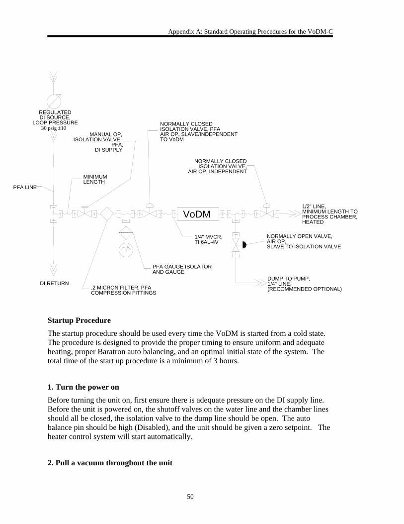
The VoDM requires some external components to perform all of the operations listed inthis document. Specifically, the VoDM should be connected as shown below with anisolation valve on the inlet and the outlet, and another on a dump line for running vapordirectly to exhaust. The water supply provided to the unit should be between 20 and 35psi.
Appendix A: Standard Operating Procedures for the VoDM-C
50
Startup ProcedureThe startup procedure should be used every time the VoDM is started from a cold state.The procedure is designed to provide the proper timing to ensure uniform and adequateheating, proper Baratron auto balancing, and an optimal initial state of the system. Thetotal time of the start up procedure is a minimum of 3 hours.
1. Turn the power onBefore turning the unit on, first ensure there is adequate pressure on the DI supply line.Before the unit is powered on, the shutoff valves on the water line and the chamber linesshould all be closed, the isolation valve to the dump line should be open. The autobalance pin should be high (Disabled), and the unit should be given a zero setpoint. Theheater control system will start automatically.
2. Pull a vacuum throughout the unit
1/2" LINE,MINIMUM LENGTH TOPROCESS CHAMBER,HEATED
DI RETURN
PFA LINE
REGULATEDDI SOURCE,
LOOP PRESSURE30 psig ±10
VoDM
.2 MICRON FILTER, PFACOMPRESSION FITTINGS
1/4" MVCR,TI 6AL-4V
MINIMUMLENGTH
NORMALLY CLOSEDISOLATION VALVE, PFAAIR OP, SLAVE/INDEPENDENTTO VoDM
PFA GAUGE ISOLATORAND GAUGE
DUMP TO PUMP,1/4" LINE,(RECOMMENDED OPTIONAL)
NORMALLY CLOSEDISOLATION VALVE,
AIR OP, INDEPENDENT
NORMALLY OPEN VALVE,AIR OP,SLAVE TO ISOLATION VALVE
MANUAL OP,ISOLATION VALVE,
PFA,DI SUPPLY

Appendix A: Standard Operating Procedures for the VoDM-C
51
Once the At_Temp bit goes low, the internal flow valve and the water valve should beopened with manual valve control. The auto balance should remain disabled and thereshould be zero setpoint. This step begins to dry out the unit and pulls a vacuum on theBaratrons to stabilize them. After an initial surge, the exhaust pressure output shouldindicate a pressure within five Torr of the system reference.
3. Auto balance
The unit must remain with the valves open, at base pressure, for at least 3 hours. The autobalance should then be activated. After approximately 1 minute, the auto balance shouldbe deactivated. This step ensures ideal conditions for the balancing of the twocapacitance manometers that measure flow. The temperature of the system and thereference base pressure must not change during this time.
4. Introduce water to the vaporizer and test flow
With the manometers now balanced, manual control should be removed from the internalvalves and a zero setpoint should be applied. The inlet water isolation valve should thenbe opened. This introduces water to the vaporizer. The exhaust pressure of the VoDMshould not rise. If it does, there is a possibility that the flow valve is leaking. Issue asetpoint corresponding to the Full Scale SCCM Flow of the unit. This should bemaintained and observed for stability for 1 minute.
5. Reduce flow
After 1 minute of stable flow, the set point should be returned to zero. Once at zero theunit is ready for service. Note: For optimal response time and performance flow 5% of FSto the dump line at all times.
Warm Startup Procedure
The following procedure should be used when the device is already warm, but has notflowed vapor for at least 8 hours. This procedure is similar to the startup procedure andwill quickly dry the unit and auto balance the Baratrons.
1. Pull a vacuum throughout the unit

Appendix A: Standard Operating Procedures for the VoDM-C
52
The external water valve should be closed, and then the internal flow valve and the watervalve should be opened with manual valve control. The auto balance should be disabledand there should be zero setpoint. This step begins to dry out the unit and holds thesystem at base pressure. After an initial surge, the exhaust pressure output shouldindicate a vacuum within 5 Torr of the reference.
2. Shut valves and engage auto balance
The unit should remain with the valves open, at reference pressure, for enough time toshow zero flow. This typically requires at least 30 min. Next, the auto balance should beengaged. After approximately 1 minute, the auto balance should be disengaged. Thisstep ensures ideal conditions for the balancing of the two capacitance manometers thatmeasure flow.
3. Introduce water to the vaporizer and test flow
With the manometers now balanced, manual control should be removed from the internalvalves and a zero setpoint should be applied. The external water valve should then beopened. This introduces water to the vaporizer. The exhaust pressure of the VoDMshould not rise. If it does, there is a possibility that the flow valve is leaking. A setpointcorresponding to the Full Scale SCCM of the unit should be provided to the VoDM.Flow should be maintained and observed for stability for 1 minute.
4. Reduce flow
After one minute of stable flow, the set point should be stepped down to zero. Then unitis ready for service.
Shutdown Procedure
In order to maintain the Baratrons and the VoDM the unit should be shutdown using thisprocedure every time it will be allowed to cool down.
1. Stop flow
Reduce the setpoint of the VoDM to zero and ensure the external dump valve is open

Appendix A: Standard Operating Procedures for the VoDM-C
53
2. Dry unit
With the dump valve open, close the external water valve. Then open the flow valve andthe water valve. This will remove all water vapor from the VoDM. Leave valves openuntil a zero flow reading is observed on the analog output. This will typically require 30minutes.
3. Shut valves and power down
Remove manual valve control from the VoDM and shut the dump valve. Set the flowsetpoint to zero. The unit is now ready to be powered down.
Health Check Procedures
The health check procedures should be run when it is suspected that something is wrongwithin the VoDM. They are tests for valve leakage and Baratron drift.
Water Valve Leak Test
1. Establish baseline
Open the dump valve and flow the Full Scale SCCM of the unit for 1 minute then let thesetpoint remain and close the water valve. Let the transients settle out of the system andthen close the flow valve. Wait one minute, this is now the baseline flow measurement,note the flow reading.
2. Test leak through water valve
With the set point still set at 2000 SCCM, open the flow valve while making sure thewater valve is shut. Note the flow reading, after an initial surge, it should not besignificantly higher than the baseline reading from step 1. If it is higher, the water valvemay be leaking.
3. Remove manual control of valves

Appendix A: Standard Operating Procedures for the VoDM-C
54
Change the setpoint to zero and put the VoDM back into control mode (i.e. disengagemanual valve control). The unit should then be ready to function normally.
Flow Valve Leak Test
1. Establish baseline
Close the internal water valve and open the external dump valve. Then open the flowvalve until the exhaust pressure in not changing. The pressure and flow that is indicatedare the baselines for this test.
2. Test leak through flow valve
While still in manual valve control mode, close the flow valve and ensure the setpoint tothe unit is zero. Then remove manual control of the valves and watch the flow andexhaust pressure. If the steady state flow rises by more than 30 SCCM then the valvemay be leaking.
3. Remove manual control of valves
Change the setpoint to 1/3 Full Scale SCCM and flow through the dump valve for severalminutes. Change the setpoint to zero. The unit should then be ready to function normally.

Appendix B: Product Specifications
55
Appendix B: Product Specifications
Electrical Specifications
Voltage Range 100-120 or 220-240 VAC
Power Requirement
Either:
100-120 VAC @ 3.5 Ampsor 220-240 VAC @ 1.6 Amps
Fuse Ratings100 VAC, 120 VAC220 VAC, 240 VAC
4.0A, 250 V1.6 A, 250 V
Performance Specifications
Flow Accuracy1 ±3.0% of full scale
Flow Rate RangeVoDMC52CR1BE: 50 sccm to 500 sccm
VoDMC13CR1BE: 100 sccm to 1 slmVoDMC33CR1BE: 300 sccm to 3 slm
Flow Repeatability ±0.2% of full scale
Flow Resolution 0.1% of full scale
Internal Operating Pressure 2000 Torr, maximum
Output Noise ±1.00% peak-to-peak at full scale
Warm up Time 3 hours
1Includes controller error, linearity, hysteresis, and repeatability.

Appendix B: Product Specifications
56
Physical Specifications
Attitude Sensitivity
Preferred orientation is horizontalIf mounted vertically, flow must be UPDo not mount the unit upside down or onits side
Cable Length, maximum(for signal output) 100 feet
Connectors:AC PowerAnalog I/O
IEC standard power entry module15-pin male Type “D”
Dimensions 13.63” H x 13” W x <5.46” D(34.6 cm H x 33.0 cm W x <13.6 cm D)
Fittings:InletOutlet
Swagelok 4-VCR maleSwagelok 8-VCR male
Mounting Detail Four ∅0.35” mounting through-holes
Vaporatizor Set PointTemperature
140° C ±10° C
Vapor Set Point(Flow Body)Temperature 125° C ±5° C
Overpressure Limit 100 psia
Weight < 32 lbs (14.5 kg)
Wetted Materials Inconel®, 316L VIM/VAR, Nickel,Titanium, Kalrez
Environmental Specifications
Ambient Operating Temperature Range 15° to 45° C (59° to 113° F)
Storage Temperature Range -20° to 80° C (-4° to 176° F)
Storage Humidity Range 0 to 95% Relative Humidity, non-condensing
Due to continuing research and development activities, these product specifications are subject to change without notice.

Appendix C: Model Code Explanation
57
Appendix C: Model Code Explanation
Model Code
The model code of your VoDM Vapor Flow Controller designates a unit designed for yourapplication. The serial number label, shown in Figure 12, page 42, lists the model code of theVoDM instrument.
VoDMC52CR1BE
VoDMC13CR1BEor
VoDMC33CR1BE
Product Type
The product type designates the model number of the instrument, which is Type VoDMC.
Full Scale Range and Flow Unit
The full scale range is:
• 500 sccm (0.5 slm) for the VoDMC52CR1BE, designated by “52C”
• 1000 sccm (1 slm) for the VoDMC13CR1BE, designated by “13C”
• 3000 sccm (3 slm) for the VoDMC33CR1BE, designated by “33C”
Fittings
The VoDM unit has a Swagelok 4-VCR male fitting on the inlet and an 8-VCR male fitting onthe outlet. This is designated by “R”.
Valve Type
The inlet and outlet valves are both normally closed. This is designated by “1”.

Appendix C: Model Code Explanation
58
Connector
The Analog I/O connector is a 15-pin Type “D” connector. This is designated by “B”.
Seals
The VoDM uses EPDM seals. This is designated by “E”.

Index
59
Index
A
AC power connector, 34
Accuracy, 38
Analog I/O, 32, 41, 58
At temperature signal, 34
Attitude sensitivity, 25, 56
Auto balance, 19, 34, 38, 46
C
Cable
extension, 22, 37
guidelines, 23
Cables
wire size, 23
Connectors, 31
AC power, 31
analog I/O, 31, 43
Analog I/O, 32, 58
clearance, 28
guidelines, 23
pinouts, 32
Controller, 30
Customer support, 20
D
Dimensions, 26, 27
E
ECU, 30
Error codes, 40
Error LED, 40
F
Filtration, 27
Fittings, 19, 57
Flow direction, 28
Flow set point signal, 43
Full scale range, 19, 57
Fuse information, 48
Fuse, replacing, 30, 48
I
Interface cables, 23
L
Labels
serial number, 42
LED, 39
error codes, 40
status, 19, 39
Liquid source, 27, 28
M
Main enclosure, 37
Manifold, recirculation, 22
Manual organization, 20
Model code, 57
Mounting, 56
Mounting instructions, 28
O
Open collector, 34
Operation

Index
60
start up, 35
status LED, 39
Optional equipment, 21
Orientation, 25, 56
Outlet line, 28
P
PID control algorithm, 38
Pinout, I/O connector, 32
Power entry module, 30, 34, 37
Power requirements, 25
Power supply, 25, 30, 37
R
Repair, 20
Restart sequence, 37
Returning the product, 20, 21
S
Safety information, 1–16
Seal material, 58
Serial number label, 42
Set point
flow, 43
signal, 43
Setup
mounting instructions, 28
power requirements, 25
Shutoff valve, 19, 25, 29
Specifications, 55
Start up, 35
warm up time, 35
Status LED, 39
System at temperature signal, 34
System configuration, 29
T
Temperature
operating, 27
warm up time, 35
V
Valve
leakage, 19, 25
positive shutoff, 19, 25, 29
type, 57
Valve control
caution, 41, 44
direct, 33, 41, 44
inlet, 33, 44
outlet, 33, 45
set point, 33, 44, 45
Ventilation, 25
Voltage setting, 30
W
Warm up time, 35
Watchdog timer, 37
Water supply, 25, 27
Z
Zero, 19, 38