Embed Size (px)
Citation preview

MKS-11GN “SPECTRA” SEARCH DOSIMETER-RADIOMETER
Operating Manual

2
CONTENTS 1 DESCRIPTION AND OPERATION ................................................................ 3 1.1 PURPOSE OF USE ............................................................................................. 3 1.2 TECHNICAL SPECIFICATIONS ........................................................................... 4 1.3 DELIVERY KIT OF THE DOSIMETER ................................................................... 9 1.4 DESIGN AND PRINCIPLE OF OPERATION .......................................................... 10 1.5 LABELING AND SEALING ............................................................................... 13 1.6 PACKING ...................................................................................................... 13 2 PROPER USE OF THE DOSIMETER ........................................................... 14 2.1 OPERATING LIMITATIONS .............................................................................. 14 2.2 PREPARATION FOR OPERATION ...................................................................... 14 2.3 USE OF THE DOSIMETER ................................................................................ 16 3 TECHNICAL MAINTENANCE .................................................................... 56 3.1 TECHNICAL MAINTENANCE OF THE DOSIMETER .............................................. 56 3.2 VERIFICATION OF THE DOSIMETER ................................................................. 57 4 CERTIFICATE OF ACCEPTANCE ................................................................ 64 5 PACKING CERTIFICATE .............................................................................. 64 6 WARRANTY ................................................................................................. 65 7 REPAIR ......................................................................................................... 66 8 STORAGE ..................................................................................................... 67 9 SHIPPING...................................................................................................... 67 10 DISPOSAL ................................................................................................... 67 APPENDIX А TROUBLE RECORD DURING USE ................................................................ 68 APPENDIX B REPAIR ............................................................................................................ 69 APPENDIX C STORAGE ........................................................................................................ 70 APPENDIX D PUTTING IN PROLONGED STORAGE AND REMOVAL FROM STORAGE ............................................................................................ 71 APPENDIX E VERIFICATION AND INSPECTION RESULTS ............................................. 72

3
This Operating Manual (hereinafter called the OM) is intended to inform the user about the principles of operation and rules of application of the search dosimeter-radiometer MKS-11GN “SPECTRA”. The manual contains all information necessary for full implementation of its technical capabilities and its proper use.
The Operator Manual contains the following abbreviations: DER - ambient dose equivalent rate of gamma, X-ray and neutron
radiation; PC - personal computer. 1 DESCRIPTION AND OPERATION
1.1 Purpose of use MKS-11GN “SPECTRA” search dosimeter-radiometer (hereinafter - the
dosimeter) is designed to
• measure ambient dose equivalent rate of gamma, X-ray and neutron radiation (photon and neutron ionizing radiation DER).
• determine gamma and neutron radiation intensity.
• identify the type of radionuclides by their amplitude gamma spectra.
• save amplitude gamma spectra and events logs in the nonvolatile memory.
The dosimeter meets the requirements of ANSI 42.48 standard. The dosimeter is used to control illicit transfer of radioactive materials and
search for sources of radioactive radiation in the following areas: • Customs and Border Services; • Law enforcement agencies (MIA, Security Service of Ukraine, safeguard
service); • Vehicles monitoring, seaports and airports; • Environmental inspectorate; • Radioactive waste storage sites.

4
1.2 Technical Specifications 1.2.1 Key specifications are presented in Table 1.1. Table 1.1
Name Measurement unit Standardized value Sensitivity to gamma radiation for (137Cs), not less than (cps)/(μSv/h) 200
Sensitivity to neutron radiation for: - Thermal neutrons, not less than - Fast neutrons, not less than
(pulse·cm2)/neutron
1.2 ± 0.12,
0.12 ± 0.012 Measurement range of photon-ionizing radiation DER μSv/h 0.01 … 106
Indication range of photon-ionizing radiation DER μSv/h 0.01 … 104
Indication range of count rate of photon-ionizing radiation cps 1 … 25000
Indication range of count rate of neutron radiation cps 0.01 … 25000
Main relative permissible error limit during photon-ionizing radiation DER measurement with 0.95 confidence probability (137Cs)
%
±(15+1/H*(10)), where H*(10) is a numeric value of measured DER
equivalent to μSv/h
Energy range of registered photon-ionizing radiation MeV 0.02 … 3.00
Energy dependence of the device readings during photon-ionizing radiation DER measurement in the energy range from 0.05 to 3.00 MeV relative to 0.662 MeV energy (137Cs)
% ±25

5
Table 1.1 (continued)
Name Measurement unit
Standardized value
Anisotropy of the dosimeter when gamma radiation is recorded at gamma quanta incidence at angles from +60о to - 60о horizontally and vertically relative to the main measurement direction, marked by a “+” symbol: - for 137Cs and 60Со isotopes - for 241Am isotope
%
30 75
Number of amplitude gamma spectrum channels channel 2048
Energy range of registered neutron radiation eV 0.025 – 14·106 Time of operating mode setting, not more than min 1
Calibration time by the level of gamma background s 2 … 60
Response time to over 10 times change of photon-ionizing radiation DER s 0.25
Operating supply voltage of the dosimeter from lithium-polymer battery V 3.7
Continuous operation of the dosimeter when powered by the charged battery under natural background radiation and switched off display backlight, not less than
hrs 45
Operating temperature range °С -20 … +50 Dimensions of the dosimeter without a clip, not more than mm 67 × 127 × 30
Weight of the dosimeter, not more than kg 0.28
6
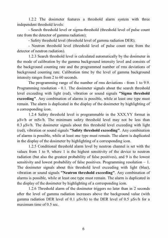
1.2.2 The dosimeter features a threshold alarm system with three independent threshold levels:
- Search threshold level or sigma-threshold (threshold level of pulse count rate from the detector of gamma radiation);
- Safety threshold level (threshold level of gamma radiation DER); - Neutron threshold level (threshold level of pulse count rate from the
detector of neutron radiation). 1.2.3 Search threshold level is calculated automatically by the dosimeter in
the mode of calibration by the gamma background intensity level and consists of the background counting rate and the programmed number of rms deviations of background counting rate. Calibration time by the level of gamma background intensity ranges from 2 to 60 seconds.
The programming range of the number of rms deviations - from 1 to 9.9. Programming resolution - 0.1. The dosimeter signals about the search threshold level exceeding with light (red), vibration or sound signals "Sigma threshold exceeding". Any combination of alarms is possible, while at least one type must remain. The alarm is duplicated in the display of the dosimeter by highlighting of a corresponding icon.
1.2.4 Safety threshold level is programmable in the XXX.YY format in µSv/h or mSv/h. The minimum safety threshold level may not be less than 0.3 µSv/h. The dosimeter signals about this threshold level exceeding with light (red), vibration or sound signals "Safety threshold exceeding". Any combination of alarms is possible, while at least one type must remain. The alarm is duplicated in the display of the dosimeter by highlighting of a corresponding icon.
1.2.5 Conditional threshold alarm level by neutron channel is set with the values from 1 to 9, where 1 is the highest sensitivity of the device to neutron radiation (but also the greatest probability of false positives), and 9 is the lowest sensitivity and lowest probability of false positives. Programming resolution – 1. The dosimeter signals about this threshold level exceeding with light (blue), vibration or sound signals "Neutron threshold exceeding". Any combination of alarms is possible, while at least one type must remain. The alarm is duplicated in the display of the dosimeter by highlighting of a corresponding icon.
1.2.6 Threshold alarm of the dosimeter triggers no later than in 2 seconds after the level of gamma radiation increases above the background value (with gamma radiation DER level of 0.1 µSv/h) to the DER level of 0.5 µSv/h for a maximum time of 0.5 sec.

7
1.2.7 The frequency of false signaling for gamma and neutron radiation - less than 1 per 10 hours of operation in a stable background environment and the following values of threshold levels:
- Search - 4; - Safety - 1 µSv/h; - Neutron - 4. 1.2.8 The dosimeter does not give false signals about the presence of
neutron radiation when exposed to gamma radiation from gamma source with 60Со or 137Cs with DER value of 100 µSv/h.
1.2.9 The dosimeter offers a possibility of automatic event logging in the nonvolatile memory, namely:
- switching the dosimeter on; - switching the dosimeter off; - search threshold level exceeding; - safety threshold level exceeding; - conditional threshold level exceeding from the detector of neutron
radiation; - saving measurement by the user’s command; - settings change by the administrator; - device’s flash memory erasing. - identification results. 1.2.10 Nonvolatile memory capacity allows storing up to 20,000 records of
registered event, as well as 250 full gamma spectra. 1.2.11 The dosimeter can identify the following gamma radionuclides: – medical radionuclides: 18F, 67Ga, 51Cr, 75Se, 89Sr, 99Mo, 99mTc, 103Pd, 111In,
123I, 125I, 131I, 153Sm, 201Tl, 133Хе; – industrial radionuclides: 57Co, 60Co, 133Ba, 137Cs, 192Ir, 152Eu, 22Na, 241Am; – special nuclear materials: 233U, 235U, 237Np, Pu [Reactor grade plutonium
(more than 6% 240Pu)]; – naturally occurring radioactive materials: 40K, 138La, 226Ra, 232Th and
decay products, 238U and decay products. 1.2.12 The library can be expanded up to 128 radionuclides via “Spectra
Reader” SW in a separate order (2.3.3.7). 1.2.13 Data communication between the dosimeter and the PC is done via
USB. 1.2.14 The dosimeter displays signs of the low battery.

8
1.2.15 The dosimeter remains operable under: - Ambient temperature from -20 to +50 °C; - Relative humidity up to 100% at 35 °C temperature without humidity
condensation; - Atmospheric pressure from 84 to 106.7 kPa. 1.2.16 The dosimeter is resistant to sinusoidal vibrations by N1 group
according to GOST 12997-84 standard. 1.2.17 The dosimeter is resistant to single shocks with the following
parameters: - Shock pulse duration - 6 ms - Maximum shock acceleration - 50 m/s2. 2.1.18 The dosimeter is resistant to falls on each of its six edges from a
height of 0.75 m on the concrete floor. 2.1.19 The dosimeter remains unaffected by constant and alternating
magnetic field of (50±1) Hz frequency and 400 A/m intensity. 2.1.20 The dosimeter is immune to gamma and X-ray radiation of up to
10 Sv/h DER for 5 minutes. 1.2.21 The ingress protection rating of the dosimeter in compliance with
GOST 14254-96 standard – is IP67. 1.2.22 The dosimeter is resistant to electromagnetic fields of frequency
range in accordance with DSTU IEC 61000-4-3: 2007 standard in the frequency range from 80 to 1000 MHz with intensity of 3 V/m (test level 2).
1.2.23 The quasi-peak value of the radio-noise field intensity at a distance of 3 m from the dosimeter does not exceed the values for class B equipment according to GOST 29216-91.

9
1.3 Delivery kit of the dosimeter 1.3.1 The delivery kit of the dosimeter includes the units and maintenance
documentation presented in Table 1.2. Table 1.2- Delivery kit
Item Type Q-ty Note MKS-11GN “SPECTRA”
search dosimeter-radiometer
ВІСТ.412139.006-02 1
Charging device 1 Model is not specified
Operating Manual ВІСТ.412139.006-02 HE 1
Spectra Reader software 1 On a mini CD
Case 1 Model is not specified

10
1.4 Design and principle of operation 1.4.1 General information, design description 1.4.1.1 Outlook of the dosimeter is shown in Figure 1.
Figure 1 – Outlook of the dosimeter

11
In terms of design, the dosimeter is made in a shape derivative of rectangular parallelepiped with replacement of flat planes with surfaces with large radii of curvature with rounded edges. The body is dustproof and waterproof, plastic. Dosimeter’s working position - vertical.
The ingress protection rating is - IP67. The body consists of two covers (1) and (2) connected by screws. The front cover (1) contains a graphical color display (3), multifunctional manipulator (joystick) (4), indicators "GAMMA" (7) "NEUTRON" (8) "BATTERY" (9) and light sensor "ABC" (10). The light panel (5) for signaling when radioactive sources are detected is located in the upper part of the cover.
A spring clip retainer (11) is secured with one screw on the back cover, with the help of which the dosimeter is securely fastened on the operator’s clothes, and which can be easily removed, if necessary. The back cover and the clip are marked with "+" symbols (12), which stand for the mechanical centers of gamma and neutron radiation detectors.
On the right lateral surface of the dosimeter’s body under the protective flexible plug (6) there is a USB connector for connecting of the peripheral devices and charging of the built-in battery.
Power supply of the dosimeter is charged by a lithium-polymer battery of 3.7 V rated voltage.
The dosimeter is sealed with a paste in the recesses (13) of the bottom cover.

12
1.4.2 Operation of the dosimeter The dosimeter consists of the following main parts: high sensitivity
detecting unit of gamma radiation (GDUh), low sensitivity detecting unit of gamma radiation (GDUl), detecting unit of neutron radiation (NDU), supply voltage formers (SVF), bias voltage formers (BVF), GPS/GNSS receiver (NAV), display and processing module (DPM), graphical color display (GCD), battery (B), thermal detector (TD).
GDUh consists of the detector of CsI(Tl) scintillator type with silicon photomultiplier and amplifier, while NDU - of the detector of LiI(Eu) scintillator type with silicon photomultiplier and amplifier. GDUl is a Geiger-Muller counter.
The principle of operation of the detecting unit is based on the transformation of scintillations in the semiconductor photomultiplier caused by gamma or neutron radiation in the scintillator into the voltage pulses. These pulses are fed to the input of the amplifier where they become amplified and come to the output as pulses of positive polarity. The number of these pulses is proportional to gamma or neutron radiation DER, and the amplitude – to the energy.
To ensure high temperature stability of the detectors with silicon photomultiplier, DPM carries out constant temperature compensation, measuring the exact values of temperature at the detectors, and precisely adjusts their bias voltage.
DPM processes the pulse flow coming from the outputs of GDUh, GDUl, NDU, and calculates the value of gamma radiation DER, which corresponds to this flow considering the multichannel amplitude analysis, and the pulse count rate from GDUh, GDUl, and NDU. Depending on the operating mode of the dosimeter, the GCD displays the readings of DER, flux intensity, intensity flow histogram, statistical error by gamma and neutron channels.
If DER exceeds 100 µSv/h by gamma channel, GDUh is automatically turned off, and the DER value is calculated from GDUl that runs continuously.
The DPM consists of the non-volatile memory, which stores entries of the events log.
13
1.5 Labeling and sealing 1.5.1 The upper cover and the panel of the dosimeter is inscribed with the
name and a symbol of the dosimeter, the ingress protection rating and the manufacturer’s trademark.
1.5.2 The lower cover of the dosimeter contains the factory serial number and the date of manufacture.
1.5.3 Sealing of the dosimeter is performed by the manufacturer. 1.5.4 Removal of seals and repeated sealing is performed by the company
after repair and calibration of the dosimeter.
1.6 Packing 1.6.1 The dosimeter, the charger and the operating manual are placed into a
dust and waterproof case. 1.6.2 The case with the dosimeter kit is put into a cardboard packing box,
which is glued up on both sides with a plastic film with a sticky layer.

14
2 PROPER USE OF THE DOSIMETER
2.1 Operating limitations
Operating limitations are presented in Table 2.1. Table 2.1 – Operating limitations
Operating limitation Limitation parameters
1 Ambient air temperature from - 20 to 50 °С
2 Relative humidity Up to 100 % at 35 °С temperature without humidity condensation
3 Effect of gamma radiation Gamma radiation DER up to 10 Sv/h during 5 min
2.2 Preparation for operation
2.2.1 Scope and order of external examination 2.2.1.1 Before using the dosimeter, unpack it and check if the delivery kit
is complete. Examine for mechanical damages. 2.2.2 Rules and order of examination for operational readiness 2.2.2.1 Read this OM carefully before you start, and examine the location
and purpose of indicators and controls. 2.2.2.2 Charge the battery by connecting the charger to the USB-port of the
dosimeter. However, if the dosimeter was on, it would automatically turn off and switch to the charging mode, and the display would show the battery charging
process animation: . Notes 1 The dosimeter is equipped with a lithium-polymer battery with no
"memory effect", which can be charged at any time. 2 Fully charge the battery before the long-term storage of the dosimeter.

15
2.2.3 List of possible troubles and troubleshooting 2.2.3.1 The list of possible troubles and troubleshooting is presented in
Table 2.2. Please record the possible troubles in the table of Appendix A of the Operating Manual.
Table 2.2 - Possible troubles and troubleshooting
Trouble, its manifestation and additional features
Probable cause Troubleshooting
The dosimeter does not switch on
The battery is discharged Charge the battery
No communication between the dosimeter and the PC
Damaged USB cable Replace the USB cable
The dosimeter’s battery does not charge
1 Damaged USB cable 2 Charging device is out of order
1 Replace the USB cable 2 Replace the charging device
2.2.3.2 At failure to eliminate the troubles presented in Table 2.2, or at
detection of more complicated troubles, the dosimeter should be sent for repair to the manufacturer.

16
2.3 Use of the dosimeter 2.3.1 Safety measures during use of the dosimeter 2.3.1.1 All works on the dosimeter use should be carried out according to
the requirements set out in the following documents: "Radiation Safety Standards of Ukraine" (NRBU-97). State hygienic
standards DHN 6.6.1-6.5.001-98, "Basic Sanitary Rules of Radiation Safety of Ukraine" (OSPU-2005) DSP
6.177-2005-09-02. 2.3.1.2 The dosimeter’s surface contains no voltages hazardous for life. 2.3.1.3 The dosimeter meets the requirements of DSTU 7237:2011
standard in terms of protection against electric shock by 0 Safety class according to GOST 12.2.007.0-75.
A special protective jacket is used to prevent accidental contact with conductive parts.
Ingress protection rating is - IP67 according to GOST 14254-96. 2.3.1.4 The dosimeter meets the requirements of GOST 12.1.004-91,
GOST 12.2.007.0-75 of fire safety. 2.3.1.5 Direct application of the dosimeter is not dangerous for personnel
and is environmentally friendly. 2.3.1.6 In the event of contamination the dosimeter is subject to
decontamination by wiping its surfaces by a gauze swab moistened with a standard decontaminating agent.
2.3.1.7 Disposal of the dosimeter should be performed in compliance with the "Laws of Ukraine" On Environmental Protection" and "On Waste", by group 4 DSanPiN 2.2.7.029-99, i.e. metal is recycled or melted, and plastic parts are dumped.
2.3.2 Operating modes of the dosimeter The dosimeter has the following modes: - Switching on/off (2.3.3.1 - 2.3.3.2); - DER measurement and indication by gamma and neutron channels
(2.3.3.3); - Intensity histograms display by gamma and neutron channels (2.3.3.4); - Radionuclides identification mode (2.3.3.5); - Setting up the dosimeter (2.3.3.6); - Mode of data communication with PC (2.3.3.7).

17
2.3.2.1 A joystick with a central button (according to Figure 1) is used to manage operation of the dosimeter.
Use the joystick to change the operating modes of the dosimeter, its settings, and navigate the menu. The central button serves to save the settings, confirm the entered data, recalibration and switching on/off the dosimeter.
2.3.2.2 A graphical color display is used to control the dosimeter’s operation.
2.3.2.3 In the process of operation the dosimeter generates the following vibration-sound and light signals.
2.3.2.3.1 Vibration and sound signals: "Quantum" - a sequence of short beeps that indicate to the intensity of
registered gamma quanta or neutrons. Signal frequency is proportional to the count rate of gamma rays or neutrons. Signal "Quantum" can be enabled or disabled only in the mode of the intensity histogram display by gamma and neutron channels.
"Sigma threshold level exceeding" - periodic light, sound and/or vibration signals that indicate to the exceeding of the intensity threshold of gamma quanta count or conventional neutrons threshold level.
"Safety threshold level exceeding" - periodic light, sound and/or vibration signals generated when the measured value of gamma radiation DER is higher than the safety threshold level.
"Low battery" - periodic light, sound and/or vibration signals that indicate to a significant discharge of the dosimeter’s battery. These signals can be completely disabled.
"Turning the dosimeter on/off" - polytonic sound, vibration and light signals, which indicate that the dosimeter was switched on or off. These signals can be completely disabled.
"Key tone" - sound and/or vibration signals generated when there was some manipulation with the dosimeter’s controls. These signals can be completely disabled.

18
2.3.3 Operation procedure of the dosimeter The general algorithm of control of the dosimeter’s operation is as follows. As soon as switched on, the dosimeter enters the mode of DER
measurement and indication by gamma and neutron channels, and starts calibration by gamma background level and testing gamma radiation detector efficiency. The duration of calibration is from 60 to 2 s depending on the gamma background DER.
An icon fully filled with green color and no flashing "background" inscription inside it indicate to the calibration completion.
Notes 1 Calibration by the level of gamma background is done automatically
when the dosimeter is switched on, after identification mode exit, or as required by the user. Calculation of the search sigma threshold level of the alarm is performed regardless of the operating mode of the dosimeter.
2 For manual recalibration while in DER measurement mode, press and hold "OK" button of the joystick for at least 2 seconds. The icon will start filling once again, and the "background" inscription will start flashing.
The dosimeter features the mode of audio alarm of registered gamma
quanta or neutrons, which turns on and off only in the mode of intensity histogram display by gamma and neutron channels. To enable/disable this mode, press and hold "OK" button of the joystick for at least 2 seconds. For recalibration in terms of intensity of sounding briefly press "OK" of the joystick.
Each short press of the joystick rightwards switches the dosimeter between
the modes in the following sequence: - the mode of DER measurement and indication by gamma and neutron
channels (2.3.3.3); - the mode of intensity histograms display by gamma and neutron channels
(2.3.3.4); - the mode of nuclide identification (2.3.3.5); - the mode of the dosimeter setup (2.3.3.6), which contains the following:
• Display (2.3.3.6.1) • Sound (2.3.3.6.2) • Vibration (2.3.3.6.3) • Light (2.3.3.6.4) • Language (2.3.3.6.5)

19
• GPS (2.3.3.6.6) • Measurement (2.3.3.6.7) • Time and Date (2.3.3.6.8) • About device (2.3.3.6.9)
By pressing the joystick leftwards, the dosimeter switches between the modes in the reverse sequence.
Regardless of the operating mode of the dosimeter, the following icons can be displayed in the top two lines of the display:
- display of the current battery status
- display of the current time
- display of the GPS-receiver status
- display of the dosimeter’s internal memory overflow
- display of the alarm threshold level exceeding
- display of the gamma background calibration process
- display of the alarm status of gamma rays or neutrons counting rate
- audible alarm status display
- vibration alarm status display
- light alarm status display
When connecting the dosimeter via the USB-cable to the PC (if the dosimeter was switched on), it automatically switches off and proceeds to the charging mode. Run the "Spectra Reader" SW and enter the correct password to switch to the mode of data communication with the PC (2.3.3.7). After completion of operation and exit from the "Spectra Reader" SW, the dosimeter automatically turns off and proceeds to the charging mode until disconnected from the PC.
2.3.3.1 Switching the dosimeter on and entering the measurement mode Hold down the central joystick button for at least 3 seconds to switch the
dosimeter on. Backlight of the graphical color display (hereinafter called the display) shows that the dosimeter is on, and then it will display information about the device and the producer’s trademark (Fig. 2).

20
If icon appears on the display when you try to turn on the dosimeter, it means that the battery is completely discharged and it should be charged (2.2.2.2).
Note – Light, sound and/or vibration signals of the dosimeter switching-on can be enabled or disabled with the help of the relevant items of the setting mode. (2.3.3.6.2 - 2.3.3.6.4).
After switching on, the display shows the login window (Fig. 3).
Figure 2 - Switching on the dosimeter
Figure 3 – Login screen
When you move the joystick up or down, choose one of the login options: "User" or "Administrator" and press the central joystick button.
Operation in the "Administrator" mode is different in that you can modify the dosimeter settings that directly affect its operation (thresholds levels of the alarm triggering by gamma and neutron channels, as well as the time and date of the device), therefore to enter the "Administrator" mode you must enter the password provided by the manufacturer of the dosimeter (Fig. 4).
Figure 4 – Entering the administrator password
21
When you move the joystick up or down, choose the required number for each section of the password and press the central button. Shifting between the sections is done by pressing the joystick leftwards or rightwards. After pressing the central joystick button, the dosimeter switches to the mode of DER measurement and indication by gamma and neutron channels (2.3.3.3).
WARNING! Do not share the login password as "Administrator" with
individuals who will use the dosimeter as "Users". They should not be able to change settings that directly affect the dosimeter’s operation.
2.3.3.2 Switching off the dosimeter Hold down the central joystick button for at least 3 seconds to switch the
dosimeter off. The display shows the information about the manufacturer and the dosimeter switches off.
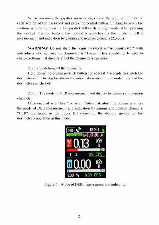
2.3.3.3 The mode of DER measurement and display by gamma and neutron
channels Once enabled as a "User" or as an "Administrator" the dosimeter enters
the mode of DER measurement and indication by gamma and neutron channels. "DER" inscription in the upper left corner of the display speaks for the dosimeter’s operation in this mode.
Figure 5 – Mode of DER measurement and indication

22
The window is divided into two independent display areas: the upper one displays DER and the pulse count rate of gamma radiation, while the lower one – DER and the pulse count rate of neutrons. The resolution of display of the pulse count rate of gamma radiation is 1 cps, that of neutrons - 0.01 cps. A unit of measurement is specified near each value, according to which the data is displayed at this point of time. An analogue scale of pulse count intensity is also present at each display area, which automatically changes the gradation depending on the radiation intensity, and a statistical error in percentage is displayed as well (Fig. 5).
If the set threshold level of alarm triggering by sigma threshold is
exceeded, icons and alternately appear in the area of icons display. If the
threshold level of alarm triggering by neutrons count rate is exceeded, icons
and alternately appear in the area of icons display, whereas triggering of both
alarms causes alternate appearance of icons and in the area of icons display. Light, sound and/or vibration alarms also turn on according to the dosimeter’s settings (2.3.3.6.2 - 2.3.3.6.4).
If the set threshold level of alarm triggering by the level of security is
exceeded, icon appears, and light, sound and/or vibration alarms also turn on according to the dosimeter’s settings (2.3.3.6.2 - 2.3.3.6.4).
Note - If you need to recalibrate the dosimeter by sigma-threshold for
gamma radiation, you should hold down the central joystick button for at least 2 seconds in the mode of DER measurement and indication by gamma and neutron channels.
IMPORTANT! If DER is over 50 µSv/h, only the alarm by the security level would trigger and it would be impossible to recalibrate the dosimeter by sigma-threshold of gamma radiation.
IMPORTANT! The effect of powerful electromagnetic radiation on the device may cause false readings and false alarms.

23
2.3.3.4 The mode of intensity histograms display by gamma and neutron channels
To switch to the mode of intensity histograms display by gamma and neutron channels, move the dosimeter’s joystick to the left or to the right (depending on the current operating mode of the dosimeter).
"FID" inscription in the left upper corner of the display indicates to operation in this mode.
Figure 6 – Histograms display mode
The window is divided into two independent display areas: the upper one reflects DER, gamma radiation pulse count rate and an intensity histogram of gamma radiation reflecting pulses for each 100 ms during the last 28 seconds, and the bottom one - DER, neutrons pulse count rate and an intensity histogram of neutron radiation reflecting pulses for each 100 ms during the last 28 sec. The resolution of display of the pulse count rate of gamma radiation is 1 cps, that of neutrons - 0.01 cps. A unit of measurement is specified near each value, according to which data is displayed at this point of time. A figure in the upper left corner of the histograms indicates its current dimension, and each point in the histogram field on the vertical axis indicates the 1/10 of this value (Fig. 6).
Note - In the absence of a neutron radiation source in the environment, the intensity histogram of neutron radiation would not be observed on the display since the common background radiation contains no neutron component.

24
If the set level of alarm triggering by sigma threshold for gamma radiation
is exceeded, icons and alternately appear in the area of icons display. If the threshold level of alarm triggering by neutrons count rate is exceeded, icons
and alternately appear in the area of icons display. Whereas triggering of
both alarms causes alternate appearance of icons and in the area of icons display. Light, sound and/or vibration alarms also turn on according to the dosimeter’s settings (2.3.3.6.2 - 2.3.3.6.4).
If the set threshold level of alarm triggering by the level of safety is
exceeded, icon appears, and light, sound and/or vibration alarms also turn on according to the dosimeter’s settings (2.3.3.6.2 - 2.3.3.6.4).
To enable and disable audio sounding of pulse count rate, hold down the central joystick button for at least 2 seconds. icon indicates to the enabled mode of pulse count rate sounding, icon - to the disabled. Short pressing of the central joystick button in the event enabled sounding of pulse count rate initiates recalibration of the sounding rate relative to the current pulse count rate, which facilitates distinguishing of sounds when the dosimeter approaches a radiation source and switch sounding from the mode of continuous signal to distinguishable periodic one.
2.3.3.5 Radionuclides identification mode To switch to the radionuclide identification mode, move the dosimeter’s
joystick to the left or to the right (depending on the current operating mode of the dosimeter).
"ID" inscription in the left upper corner of the display indicates to operation in this mode.
Figure 7 – Radionuclides identification mode

25
The radionuclides identification mode consists of the following items (Fig. 7): • Identification start - launching the identification process, • Saved spectra - viewing saved spectra (2.3.3.5.4) To go to the desired item, move the dosimeter’s joystick up or down until
this option is highlighted with a cursor, then press the central joystick button to confirm switching to the item.
2.3.3.5.1 Identification of radionuclides The dosimeter contains a library of 32 radionuclides capacity (1.2.11). The
library can be expanded up to 128 radionuclides via “Spectra Reader” SW in a separate order (2.3.3.7).
To start the process of identification of radionuclides switch to the item "Start identification", the display will show the following screen (Fig. 8):
Figure 8 – Radionuclides identification process
This window shows the following data: The top part displays the ambient dose equivalent rate; time in seconds
since the beginning of identification, and pulse count rate of gamma radiation. There is a field below that will display radionuclides found. Below this field, there is a scale displaying the time in seconds remaining to the automatic stop of the identification process.
The bottom part of the window contains the following items: • Expert Mode - switch to the expert mode (2.3.3.5.3) • Stop ID - forced stop of the identification process. Warning! In the process of identification, the appropriate filed may
temporarily display radionuclides, which in reality are absent in the ionizing radiation. Reliable information will be displayed after the period of analysis in 300 seconds and automatic stop of the identification process.

26
2.3.3.5.2 Completion of the identification process After automatic or forced stop of the identification process the following
screen appears:
Figure 9 – Identification process completion
This window shows the following data: The top part displays the ambient dose equivalent rate; time in seconds
since the beginning of identification, and pulse count rate of gamma radiation. There is a field below that will display radionuclides found, or the caption "Nuclides not found" if radionuclides are not detected.
In case radionuclides are detected, they appear in the corresponding field in
the following format: NAME CATEGORY PEAKS RELIABILITY, where: • NAME - name of the radionuclide (e.g., Co60); • CATEGORY - the category to which the identified radionuclide
belongs (“NORM” - natural, “TECH” - industrial, “MED” - medical, “SPEC” - special nuclear materials);
• PEAKS - displayed as X/Y (for example, 2/2), where Y - the number of peaks in a given radionuclide, and X - how many of them were identified;
• RELIABILITY - reliability of determination of the given radionuclide on a 10-point scale. "10" is the maximum level of reliability.
If some nuclide is not identified, the field will display the inscription
“UNKN”.

27

28
If the number of identified radionuclides is too big for simultaneous display in the field, move the dosimeter’s joystick down as many times as required to go down the list and their viewing.
The bottom part of the window contains the following items: • Continue ID - continue identification, • Save spectrum – save spectrum in the dosimeter’s memory, • Exit ID – exit to the main window of the radionuclide identification mode
(2.3.3.5). The dosimeter’s memory can store about 250 full gamma spectra. If icons
and alternately appear in the top line of the display, it means that the memory is full and further saving of the gamma spectrums is impossible. To read the gamma spectrums and delete them from the dosimeter’s memory use the "Spectra Reader" software (2.3.3.7).
Notice! If after auto completion of identification you continue it by
clicking "Continue ID", automatic completion would no longer take place, and you have to do this manually by selecting "Stop ID" (2.3.3.5.1).
2.3.3.5.3 Expert Mode Expert Mode allows detailed analysis of accumulated spectrum and
viewing the found peaks. To switch to the Expert Mode, select "Expert Mode" during identification of radionuclides (2.3.3.5.1).
Expert Mode window appears (Fig. 10):
Figure 10 – Expert mode

29
This window displays the following: The top part displays the ambient dose equivalent rate; time in seconds
since the beginning of identification, and pulse count rate of gamma radiation. There is a field below that displays the accumulated spectrum. The whole amplitude gamma spectrum is displayed in red color, and a zone of interest of the detected photopeak - in yellow.
Below this field there are scales in ЕХХХХ ХХХХ and АХХХХХХ ХХХХХХ formats, reflecting the lower and upper limits of the energy range (in keV) and amplitude gamma spectrum (in pulses) which are currently displayed on the screen.
Icons are located in the bottom part of the window. They are selected by
moving the joystick to the left or to the right, and then by pressing the central joystick button.
- return to a standard spectrum scale,
- spectrum scaling up or down. Moving the device’s joystick to the right increases scaling by the energy, to the left - decreases. Moving the joystick up increases scaling by amplitude gamma spectrum, down - decreases (Fig. 11):
Figure 11 – Spectrum scaling
- moving through a scalable spectrum. By moving the device’s joystick in the desired direction, you can see scalable spectrum parts in more detail (Fig. 12):

30
Figure 12 – Moving through a spectrum
- cursor display allows viewing a particular spectrum channel. Moving the device’s joystick to the right moves the cursor five pixels of the display rightwards, to the left - five display pixels leftwards. Move the device’s joystick up to move the cursor one display pixel rightwards, down - one display pixel leftwards. (Fig. 13):
Figure 13 – Cursor display
- viewing the identified peaks. If the number of identified radionuclides is too big for simultaneous display in the field, move the dosimeter’s joystick down as many times as required to go down the list and their viewing (Fig. 14). Peaks are displayed in the following format:
ITEM NO. ENERGY keV RADIONUCLIDE NAME

31
Figure 14 – Viewing identified peaks
- exiting the expert mode to identification window (Fig. 8). Notice! Exiting the expert mode does not finish the process of radionuclides identification. To stop the identification process, wait for the auto completion or switch to "Stop ID" item (2.3.3.5.1 - 2.3.3.5.2).
2.3.3.5.4 Viewing saved spectra You can view spectra saved in the dosimeter’s memory by switching to the
item "Saved spectra" in the radionuclides identification mode (2.3.3.5). The following window opens:
Figure 15 – Viewing a list of saved spectra

32
This window contains the list of spectra saved in the dosimeter’s memory. If the number of saved spectra is too big for simultaneous display in the field, move the dosimeter’s joystick down as many times as required to go down the list and their viewing (Fig. 15). Saved spectra are displayed in the following format
ITEM NO. DATE TIME
To select the required record, put the cursor over it and press the central joystick button. A window of detailed viewing of saved spectrum opens:
Figure 16 – Detailed viewing of saved spectra
Viewing control and the way of data display are identical to operation in expert mode during the radionuclides identification process (2.3.3.5.3)

33
2.3.3.6 The mode of the dosimeter setup To switch to the setup mode, move the dosimeter’s joystick to the left or to
the right (depending on the current operating mode of the dosimeter). "SET" inscription in the left upper corner of the display indicates to
operation in this mode.
Figure 17 – Dosimeter setup mode
The dosimeter setup mode includes the following items (Fig. 17):
• Display – backlight setup, • Sound – setup of sound notifications and alarms, • Vibro – setup of vibrating notifications and alarms, • Light – setup of light notifications and alarms, • Language – choice of data display language on the dosimeter display, • GPS – configuration of the dosimeter’s GPS-receiver, • Measurements – setting thresholds of the alarm triggering and tracks
saving, • Time&Date – setting the time and the date, • Device Info – Information about the device and the manufacturer.
To switch to the desired item of settings, move the dosimeter’s joystick up
or down until this item becomes highlighted by the cursor, then press the central joystick button to confirm switching to this item.
To change the settings in items "Display", "Sound", "Vibro", "Light" and "GPS", move the dosimeter’s joystick up or down until you select the desired option, then move the dosimeter’s joystick leftwards or rightwards to select ,
or a different value depending on the selected parameter.
34
To change the settings in the "Language" item, move the dosimeter’s joystick up or down until you select the desired language, then press the central joystick button to confirm your choice.
To change the settings in items "Measurements", "Time&Date" and sub-item "Change Password" of the item "Device Info", move the dosimeter’s joystick up or down until you select the desired option, then press the central joystick button to confirm your choice. Then, you should move the dosimeter’s joystick leftwards or rightwards until you select the desired value or unit of measurement, and then move the joystick up or down until you select the desired value. Press the central button of the joystick to return to selection of other parameters of the respective item.
Each item of the setup menu contains icons (in addition to "About Device") and responsible for saving the settings and returning to the previous menu without saving settings respectively. To select the desired icon, move the dosimeter’s joystick up or down until this icon becomes highlighted with green cursor (for example, ), then press the central joystick button to confirm.
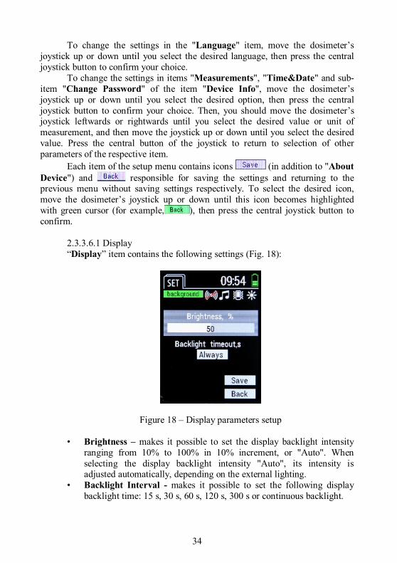
2.3.3.6.1 Display “Display” item contains the following settings (Fig. 18):
Figure 18 – Display parameters setup
• Brightness – makes it possible to set the display backlight intensity ranging from 10% to 100% in 10% increment, or "Auto". When selecting the display backlight intensity "Auto", its intensity is adjusted automatically, depending on the external lighting.
• Backlight Interval - makes it possible to set the following display backlight time: 15 s, 30 s, 60 s, 120 s, 300 s or continuous backlight.

35
2.3.3.6.2 Sound “Sound” item contains the following settings (Fig. 19):
Figure 19 – Setup of sound signals
• Sound ON – makes it possible to enable or disable the beeps when switching the dosimeter on and off;
• Sound Keys – makes it possible to enable or disable sounding of manipulation with the dosimeter controls;
• Sound Signal – makes it possible to enable or disable the audible alarm triggered by exceeding the threshold level of radiation;
• Sound Bat. – makes it possible to enable or disable the audible alarm when the dosimeter’s battery is discharged.

36
2.3.3.6.3 Vibration “Vibration” item contains the following settings (Fig. 20):
Figure 20 – Setup of vibration signals
• Vibr. ON – makes it possible to enable or disable vibration signals when switching the dosimeter on and off;
• Vibr. Keys – makes it possible to enable or disable vibration during manipulation with the dosimeter controls;
• Vibr. Signal – makes it possible to enable or disable the vibration alarm triggered by exceeding the threshold level of radiation;
• Vibr. Bat. – makes it possible to enable or disable the vibration alarm when the dosimeter’s battery is discharged.

37
2.3.3.6.4 Light “Light” item contains the following settings (Fig. 21):
Figure 21 – Setup of light signals
• Light ON – makes it possible to enable or disable light signals when switching the dosimeter on and off;
• Light Signal – makes it possible to enable or disable the light alarm triggered by exceeding the threshold level of radiation;
• Light Bat. – makes it possible to enable or disable the light alarm when the dosimeter’s battery is discharged.

38
2.3.3.6.5 Language “Language” item makes it possible to change the data display language on
the dosimeter display (Fig. 22):
Figure 22 – Language setup 2.3.3.6.6 GPS “GPS” item contains the following settings (Fig. 23):
Figure 23 – GPS-receiver parameters setup

39
• GPS power supply - makes it possible to enable or disable the dosimeter’s GPS-receiver;
• GPS data update - makes it possible to set the following coordinates update interval: 15 s, 30 s, 60 s, 120 s, 300 s or continuous update;
• GPS information - makes it possible to switch to viewing the current data of GPS-receiver, namely, time, date, coordinates, number of satellites currently found by the device (SIU), as well as information on whether these coordinates are reliable (Fig. 24).
Figure 24 – GPS information

40
2.3.3.6.7 Measurement “Measurement” item contains the following settings (Fig. 25):
Figure 25 – Measurement parameters setup
• Sigma threshold Gamma - makes it possible to set the threshold of the alarm triggering by the number of exceedances of the mean square value of pulse count rate of gamma radiation;
• Conditional threshold Neutrons - makes it possible to set the conditional threshold of the alarm triggering by neutrons;
• Safety Threshold - makes it possible to set the threshold of the alarm triggering by the DER value;
• Save measurements - allows saving the events with current coordinates, time and DER in the dosimeter’s memory during measurement. If GPS-receiver was disabled at the time of saving, or there was no communication with satellites, information about current coordinates is not be added to the event.
IMPORTANT! The options to configure "Sigma threshold Gamma", "Conditional threshold Neutrons" and "Security Threshold" are available only after logging in the "Administrator" mode (2.3.3.1).
The dosimeter’s memory allows storing about 20,000 events. If
and icons alternatively appear in the top line of the display, it means that the dosimeter’s memory is full and a further saving of events is impossible. To read the events and clear those from the dosimeter’s memory use the "Spectra Reader" software (2.3.3.7)
41
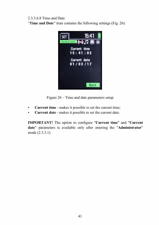
2.3.3.6.8 Time and Date “Time and Date” item contains the following settings (Fig. 26):
Figure 26 – Time and date parameters setup
• Current time - makes it possible to set the current time; • Current date - makes it possible to set the current date.
IMPORTANT! The option to configure "Current time" and "Current date" parameters is available only after entering the "Administrator" mode (2.3.3.1).

42
2.3.3.6.9 About the device Item "About the device" contains information about the model of the
dosimeter, version of its trademark software, serial number, and information about the dosimeter’s manufacturer (Fig. 27).
Figure 27 – About the device
This item also contains the subitem "Change password" that allows you to change the password in the "Administrator" mode (2.3.3.1).
The subitem "Change Password" contains the following items (Fig. 28):
Figure 28 – Password change
• Enter password - enter the current password in this field; • Enter new password - enter a new password in this field; • Repeat new password - reenter the new password in this field.
43
2.3.3.7 Data communication with PC 2.3.3.7.1 Installation of software To read and review the events from the dosimeter and setting its parameters
use the "Spectra Reader" software (hereinafter "Spectra Reader" SW), which is supplied by the dosimeter’s manufacturer.
IMPORTANT! You need to know the password to log in as "Administrator" to use the "Spectra Reader" SW. It is common for operation with the dosimeter and this SW.
To realize the option of data communication of the dosimeter and the personal computer (hereinafter PC) you first need to install the driver supplied by the dosimeter’s manufacturer.
After installing the driver, you have to install the "Spectra Reader" SW. Installation of drivers and "Spectra Reader" SW is similar to installing
other applications and does not require any special skills. IMPORTANT! Smooth operation of "Spectra Reader" SW requires
installation on the PC of the OS Windows 7 and higher. To install the driver and "Spectra Reader" SW you might need to login in the OS of your PC as the "Administrator". In case of complications, please contact your system administrator who supports your PC.
2.3.3.7.2 Setting data communication with PC Connect the dosimeter via USB-cable to the PC. If the dosimeter is
switched on, it automatically switches off and proceeds to charging mode. To switch to the mode of data communication with PC you have to run "Spectra Reader" SW (through a link on the desktop or via "Start" menu), after which you see a login window into the "Spectra Reader" SW containing the following fields (Fig. 29):
• Language – selection of the desired language of interface display; • COM-port - selection of a COM-port, which the dosimeter is connected to; • PIN code - entering a PIN code to access the program.

44
Note – You may get to know the COM-port number by clicking the right mouse button on the icon "Computer" and selecting "Properties" in the popup window. Then in the left side of the window that appears, select "Device Manager" item and in the "Ports (COM and LPT)" tab find "ST Microelectronics Virtual COM Port". COM-port (COM__) number specified opposite the device is used to select the login window to "Spectra Reader" SW in the "COM-port" field. If you connect the dosimeter to the same USB-port of the PC each time, the number of its COM-port does not change. An example of access to information about the COM-port number is provided for Windows 7 and may vary in other operating systems.
Figure 29 – Login window in "Spectra Reader" SW Select the desired options, enter a PIN code and click "Apply" button. If all
data was entered correctly, “Events” tab of the "Spectra Reader" program opens (2.3.3.7.3-2.3.3.7.4). If a window appears with a warning that your data is incorrect, check the entered data and click "Apply" again.

45
2.3.3.7.3 Events reading After starting the "Spectra Reader" SW, the main window’s tab "Events"
opens, which allows managing the events saved in the dosimeter’s memory (Fig. 30).
Figure 30 – "Events" tab
In the upper left corner of the "Events" tab a serial number of the connected dosimeter is highlighted in the format "Ser.number ХХХХХХХХ", where ХХХХХХХХ is a unique serial number of the currently connected dosimeter.
This tab has the following fields as well: • List of events - this field displays the list of events downloaded from the
dosimeter during the last readout session (2.3.3.7.4); • Events Filter - in this field you can select the type and the date of saved
events that will be displayed in the list after reading from the dosimeter (2.3.3.7.4).
Click "Read events" to read all events stored in the dosimeter’s memory. IMPORTANT! Even if not all types of events were selected in the
"Events Filter" field, they still would be read again each time until cleared from the dosimeter’s memory (2.3.3.7.4).

46
2.3.3.7.4 Working with the readout events After successful reading of the events from the dosimeter (2.3.3.7.3), they
are displayed in the "List of Events" field of the "Events" tab (Fig. 31).
Figure 31 – Readout events
Select the required event in the "List of events" field. The information it contains is displayed rightwards below the "Events Filter" field.
If you need to sort the downloaded events, you can check the boxes in the "Events Filter" field opposite those types of events to be displayed in the "List of Events" field.
You can also set the time interval to display the events, the date of creation of which falls within this interval. To do this you have to check the box opposite the fields "from" and "to" and set the desired time interval.
After selecting the types of events and/or the time interval, click "Apply" to display the events according to the specified parameters.
"Clear events" button is designed to delete all events from the dosimeter’s memory.
IMPORTANT! If the events were not stored on the PC’s hard drive (or removable disc), they are not subject to recovery after removal from the dosimeter’s memory.

47
The upper right corner of the "Events" tab contains the following buttons of the events control:
- saving all events to the PC’s hard drive in the .dat format (including those that are not displayed according to filters);
- download the saved events from the PC’s hard drive;
- save all events to the PC’s hard drive in .html format;
- printout the report;
- display the event on the map, according to the coordinates where it was saved (if the coordinates have been added, 2.3.3.6.7) (Fig. 32).
Figure 32 – Event display on the map

48
2.3.3.7.5 Spectra "Spectra" tab allows managing spectra saved in the dosimeter’s memory
(Fig. 33).
Figure 33 – "Spectra" tab
In the upper left corner of the "Events" tab a serial number of the connected dosimeter is highlighted in the format "Ser.number ХХХХХХХХ", where ХХХХХХХХ is a unique serial number of the currently connected dosimeter.
This tab includes the following fields as well: • Spectra list - this field displays a list of spectra downloaded from the
dosimeter during the last readout session (2.3.3.7.6); • Field of detailed spectra viewing - in this field you can view the details
of spectra that were read from the dosimeter (2.3.3.7.6) • Cursor - allows channel-by-channel preview of the selected spectra, • Filter by date - in this field you can select a date of spectra saving to be
displayed in the list after reading from the dosimeter (2.3.3.7.6). Click the "Read spectra" button to read all spectra saved in the
dosimeter’s memory.

49
IMPORTANT! Even if not all dates of spectra saving were selected in the field of filtering by date, they still would be read again each time until cleared from the dosimeter’s memory (2.3.3.7.6).
2.3.3.7.6 Working with the read spectra After successfully spectra reading from the dosimeter (2.3.3.7.5), they are
displayed in the "Spectra list" field of "Spectra" tab (Fig. 34).
Figure 34 – Read spectra
Select the necessary entry in the "Spectra list" field by the date and time of creation. The information it contains is displayed to the right in the field of detailed spectra viewing. You can view the required saved spectrum channel-by-channel in this field by controlling the cursor using the corresponding arrows in the "Cursor" field. Depending on the current position of the cursor in the "Cursor" field information about the channel, energy (in keV) and the number of pulses will be displayed. In addition, there is “Lin/Log” checkbox over the field of detailed spectra viewing, which allows you to switch between spectra display scale from linear to logarithmic, or vice versa. To the left of the "Cursor" field you may see the ambient dose equivalent rate and the number of pulses per second per spectrum saving time, as well as its total accumulation time. Below the field detailed spectra viewing, there is information about calibration by energy.

50
If you need to sort the loaded spectra, you may set time interval in the field of filtering by date to display spectra, which creation date falls in this interval. You should put a tick opposite fields "from" and "to" and set the desired time interval. After selecting the time interval, click "Apply" to display spectra in accordance with the specified parameters.
Button "Delete spectra" is designed to delete all saved spectra from the
dosimeter’s memory. IMPORTANT! If the spectra were not stored on the PC’s hard drive (or
removable disc), they are not subject to recovery after removal from the dosimeter’s memory.
In the upper right corner of the 'Spectra' tab, there is a button that allows you to export information about this spectrum in .xml format in accordance with ANSI 42.42 requirements.
2.3.3.7.7 Library of nuclides "Library of nuclides" tab allows you to manage the library of
radionuclides saved in the dosimeter’s memory (Fig. 35).
Figure 35 – "Library of nuclides" tab

51
There is a field of radionuclide libraries viewing downloaded from a file in the left part of this tab (2.3.3.7.8).
The right part of this tab contains the following buttons: • Read library from file – allows loading a library of radionuclides from a
file (2.3.3.7.8); • Download library in the device - allows loading a library of
radionuclides in the dosimeter (2.3.3.7.8); • Clear library - allows deleting the library of radionuclides, which is
currently in the dosimeter. Notice! After deletion of library of radionuclides from the dosimeter, you
should load another one; otherwise, the dosimeter would not be able to exercise identification of radionuclides, although the search mode remains functioning.
2.3.3.7.8 Managing libraries of radionuclides To download a new library in the dosimeter first read it into the "Spectra
Reader" program from a file in .bn format. Library file is provided by the dosimeter manufacturer in a separate order.
Click "Read library from file" button to open the following window:
Figure 36 – Reading library of nuclides from file
Select the directory where the file with the library is located and click "Open". You will see the following window:

52
Figure 37 – Library of nuclides read from file
In the field of viewing libraries of radionuclides appearі a list of radionuclides contained in the read file in the following format:
ITE NO. NAME CATEGORY, where
• ITEM NO. – is a serial number of the radionuclide; • NAME – a name of the radionuclide (e.g., Co60); • CATEGORY – the category to which the identified radionuclide belongs (“Natural” - natural, “Technical” - industrial, “c” - medical, “Nuclear” - special nuclear materials, “Other” - other); Click "Clear library" button to delete the library of radionuclides, which is currently in the dosimeter, and then load a new library of radionuclides in the dosimeter using the "Download library in the device" button. Wait for completion of the library downloading in the device. Notice! Previous library must be deleted from the dosimeter’s memory before loading a new one, otherwise, when trying to load a corresponding warning appears.

53
2.3.3.7.9 Settings "Settings" tab allows you to configure the dosimeter operation parameters and change its PIN code (Fig. 38).
Figure 38 – Settings tab "Settings" tab includes the following fields: • Serial No. - this field displays the unique serial number of the connected
dosimeter; • Sigma threshold by gamma - set the threshold of alarm triggering in this
field by the number of rms deviations of gamma radiation pulse count rate; • Conditional threshold by neutrons - in this field you can set the
threshold of the alarm triggering by the neutrons count rate; • Safety threshold by gamma - in this field you can set the threshold of
the alarm triggering by gamma radiation DER level; • Date/Time - in this field you can enter the current date and time or check
the box in the "Synchronization" line and click "Update" to read the system time from the PC.
After entering the required data, click "Save settings" to record the updated data in the dosimeter’s memory.

54
2.3.3.7.10 PIN code change
To change the PIN code of access to "Spectra Reader" SW and login as the "Administrator" in the dosimeter, click on the "Change PIN code" button on the right side of the "Settings" tab of the "Spectra Reader" SW’s main window (Fig. 38).
A field of the PIN code change opens featuring the following fields (Fig. 39):
Figure 39 – PIN code change • PIN code - enter the current access PIN code in this field;
• New PIN code - enter a new access PIN code in this field; • Repeat new PIN code - renter the new access PIN code in this field.
Click "Apply" to save the new PIN code or "Cancel" to keep the current PIN code unchanged.

55
2.3.3.7.11 Map On the "Map" tab you can view all points on the map downloaded during
the last reading according to the coordinates where they were saved (Fig. 40).
Figure 40 – “Map” tab 2.3.3.7.12 Completion of operation in the mode of data communication
with PC After completion of work and exiting the "Spectra Reader" SW, the
dosimeter automatically turns off and switches to the charging mode until it is disconnected from the PC.

56
3 TECHNICAL MAINTENANCE
3.1 Technical maintenance of the dosimeter 3.1.1 General guidelines The list of operations during technical maintenance (hereinafter - TM) of
the dosimeter, the order of priority and features at different stages of the dosimeter use is shown in Table 3.1.
Table 3.1 - List of operations during technical maintenance
Operations
Type of technical maintenance OM item No.
during during long-term
storage everyday
use periodica
l use External examination Delivery kit completeness check Operability check Storage battery status control Verification of the dosimeter
+ - + + -
+
+ + + +
+
+ + + +
3.1.3.1
3.1.3.2 3.1.3.3 3.1.3.4
3.2 Notes 1 “+” means the operation is applicable at this type of TM; “-” means the operation is not applicable. 2 The dosimeters should be verified after manufacture and repair.
3.1.2 Safety measures TM safety measures fully comply with safety measures presented in OM
2.3.1. 3.1.3 TM procedure of the dosimeter 3.1.3.1 External examination Examination of the dosimeter should be performed in the following order: а) check the condition of the dosimeter’s surfaces, the integrity of seals,
absence of scratches, traces of corrosion, and surface damage of the coating; b) check the condition of the USB socket contacts. 3.1.3.2 Delivery kit completeness check Check if the delivery kit is complete according to Table 1.2.

57
3.1.3.3 Operability check of the dosimeter 3.1.3.3.1 Operability check of the dosimeter and its procedure are
performed according to OM 2.3.3. 3.1.3.4 Storage battery status control The dosimeter’s battery status control is performed during daily use, and
before the long-term storage of the dosimeter. Follow the next procedure: - Switch on the dosimeter; - Monitor the battery’s state-of-charge by the indicator on the display; - If the battery is not full, charge it by plugging the charger in the USB
socket.
3.2 Verification of the dosimeter The dosimeters should be verified immediately after manufacture, during
use (periodic verification at least once a year), as well as after repair. 3.2.1 Verification operations During verification the operations presented in Table 3.2 should be
performed. Table 3.2 - Verification operations
Operations Verification technique No.
1 External examination 3.2.4.1 2 Testing 3.2.4.2 3 Calculation of the main relative permissible error limit during gamma radiation DER measurement
3.2.4.3
4 Verification of the ability to identify the radionuclides and their categories 3.2.4.4

58
3.2.2 Verification facilities
The following facilities that should be used for verification are given in Table 3.3:
Table 3.3
Name Regulatory documents or technical specifications
УПГД-3Б standard equipment Ambient dose equivalent rate of gamma radiation in the range from 0.1 to 106 µSv/h. Energy range from 59 kеV to 1.25 MeV. Main relative permissible error limit of gamma radiation DER and DE – 4 % with confidence probability of 0.95
УКПН-1М working standard unit of neutron radiation
Thermal neutron flux density in the range from 10 to 500 cm-2∙s-1. Main relative permissible error limit of thermal neutron flux density with confidence probability of 0.95 - 5 %.
Aspiration psychrometer МВ-4М
Л82.844.000 ПС. Temperature measurement range from –30 to +100 0С. Temperature measurement error 0.1 0С. Relative humidity measurement range from 10 to 100 %. Relative error of relative humidity measurement in the range from 12 % at t = –10 0С to 2 % at t = +30 0С.
Control aneroid barometer М-67
Л62.832.003 ПС. Pressure measurement range from 81.3 to 105.3 kPа (from 610 to 790 mmHg). Pressure measurement error limit is 0.107 kPа (0.8 mmHg)
RKS-01 “STORA” gamma, beta radiation radiometer-dosimeter
ТУ У 33.2-22362867-008-2004. 1. Gamma radiation DER measurement range from 0.1 to 1000 µSv/h. 2. Main relative permissible error limit of gamma radiation DER with the energy of 0.662 MeV is 15 % at Р=0.95.
Notes 1. All verification facilities are to be tested and verified according to the requirements of national standards DSTU 3215-95 and DSTU 2708:2006. 2. The use of other items of measuring equipment that meet the prescribed accuracy is also applicable.

59
3.2.3 Verification conditions 3.2.3.1 The verification test should be carried out under the following
conditions: - ambient air temperature within (20±5) °С; - relative air humidity within (65±15) %; - atmospheric pressure from 84 kPa to 106.7 kPa; - natural gamma radiation background should not exceed 0.25 µSv/h; - the dosimeter’s power supply from the newly charged storage battery. 3.2.4 Verification procedure 3.2.4.1 External examination During external examination the dosimeter should meet the following
requirements: - the delivery kit should be completed as described in OM 1.3; - labeling should be accurate; - Quality Control Department seals should not be violated; - the dosimeter should be free from mechanical damage that may affect its
performance. Note – The delivery kit of the dosimeter is checked only at manufacture. 3.2.4.2 Testing 3.2.4.2.1 Switch on the dosimeter according to OM 2.3.3.1 and proceed to
calibration relative to gamma background. 3.2.4.2.2 Place the 137Cs standard spectrometry gamma sources OSGI near
the dosimeter and observe the increase of pulse count rate from the gamma radiation detector above the background level, and alarm triggering when an automatically set search threshold level is exceeded.
3.2.4.2.3 Place the dosimeter in the УКПН-1М carriage holder so that the mechanical center of neutron radiation beam coincides with the one of the dosimeter’s neutron detector. Place the УКПН-1М carriage holder with the dosimeter in the position, where neutron radiation from 239Pu-Be ensures pulse count rate from the neutron radiation detector within a 10 – 20 s-1 range. Make sure that the alarm of neutron radiation is triggered.
3.2.4.2.4 Switch off the dosimeter according to OM 2.3.3.2.

60
3.2.4.3 Calculation of the main relative permissible error limit during gamma radiation DER measurement
3.2.4.3.1 Prepare the testing equipment УПГД-3Б according to its Operating Manual.
Place the dosimeter in the УПГД-3Б carriage holder so that the mechanical center of gamma beam coincides with the mechanical center of the dosimeter’s gamma detector.
Notes 1 The mechanical center of the gamma detector is labeled "+" on
dosimeter’s back cover. 2 The distance between the mechanical center of the source and the
mechanical center of the dosimeter’s gamma detector is considered to be the distance between the mechanical center of the source and the plane, which is perpendicular to the direction of gamma quanta beam propagation, and passes through the mechanical center of the dosimeter’s gamma detector in this plane.
Switch on the dosimeter. Turn off the sound and vibration alarms of the threshold levels.
Make five measurements of gamma background DER )10(*iH in УПГД-
3Б with an interval of 10 seconds. Register the obtained readings in the protocol.
Calculate the average value of )10(*H , µSv/h, by the formula:
5
)10()10(
5
1
*
* i
iHH
(3.1)
3.2.4.3.2 Place the УПГД-3Б carriage holder with the dosimeter in the position, where gamma radiation DER from the source 137Cs is )10(0
*H =(0.8 0.1) µSv/h. After the device has been exposed to radiation, wait for 5 s and proceed to take five measurements of gamma radiation DER with a 10 s interval. Calculate the average value of gamma radiation DER ( )10(*
H ) by the formula (3.1). The
value of gamma radiation DER without gamma background DER in УПГД-3Б
)10(*H , µSv/h, is calculated as follows:
)10()10()10( ***ФHHH , (3.2)
where )10(*H - is an average value of the device readings from the
source and gamma background in УПГД-3Б calculated by the formula (3.1), µSv/h;
)10(*ФH - is an average value of the dosimeter’s readings during gamma
61
background measurement in УПГД-3Б, µSv/h. 3.2.4.3.3 Determine the main relative permissible error of gamma radiation
DER measurement in percentage by the method in accordance with DSTU GOST 8.207: 2008 standard.
3.2.4.3.3.1 Calculate the confidence limit of relative random error of measurement results as follows:
St , (3.3) where t = 2.78 - a Student's coefficient at the confidence probability
Р = 0.95 and n = 5; S - a relative root-mean-square deviation of measurement result calculated
by the formula:
)1(
)10()10(
)10(1 1
2
nn
HH
HS
n
ii
(3.4) 3.2.4.3.3.2 Calculate the limit of residual systematic error of measurement
results by the formula 2*
0
2
*0
*0
2)10(
)10()10()10(1,1
HH
HH
, (3.5) where )10(*
0H - is the main relative permissible error limit of gamma radiation DER from the УПГД-3Б.
3.2.4.3.3.3 If 8.0S
, then 100)10( H .
3.2.4.3.3.4 If 8
S , then 100)10( H .
3.2.4.3.3.5 If 88.0 S
, then 100)10( SKH ,
where К - is the coefficient which depends on the ratio between the random and residual systematic errors, and is calculated by the formula:
3
SK
, (3.6) SΣ - is an evaluation of the total root-mean-square deviation of
measurement result defined as follows:

62
22
3
SS
(3.7) 3.2.4.3.4 Perform operation 3.2.4.3.2, 3.2.4.3.3 for gamma radiation DER
)10(*0H = (8 1) µSv/h in 5 seconds after irradiation of the dosimeter starts.
3.2.4.3.5 Perform operation 3.2.4.3.2, 3.2.4.3.3 for gamma radiation DER )10(*
0H = (80 8) µSv/h. 3.2.4.3.6 Perform operation 3.2.4.3.2, 3.2.4.3.3 for gamma radiation DER )10(0
*H = (800 8) µSv/h. 3.2.4.3.7 Perform operation 3.2.4.3.2, 3.2.4.3.3 for gamma radiation DER )10(0
*H = (8.0 0.8) mSv/h. 3.2.4.3.8 Perform operation 3.2.4.3.2, 3.2.4.3.3 for gamma radiation DER )10(0
*H = (80 8) mSv/h. 3.2.4.3.9 Perform operation 3.2.4.3.2, 3.2.4.3.3 for gamma radiation DER )10(0
*H = (800 80) mSv/h. 3.2.4.3.10 The dosimeter is acknowledged to have passed the verification
test if the main relative permissible error at measurement of each level of gamma
radiation DER does not exceed (15+1/ )10(*H ) %, where )10(*H is a measured
value of gamma radiation DER equivalent to μSv/h. 3.2.4.4 Verification of the ability to identify the radionuclides and their
categories 3.2.4.4.1 Turn on the dosimeter. Turn off sound and vibration alarms of
threshold levels. 3.2.4.4.2 Expose the dosimeter’s detector with 137Cs gamma radiation
source, with DER of gamma radiation between from 1 to 10 μSv/h. Chose the radionuclide identification mode and start the identification process. After automatic finish of the identification process read the results. Repeat the test 9 additional times.
3.2.4.4.3 Repeat 3.2.4.4.2 for 241Am and 60Co radionuclides. 3.2.4.5.4 The verification result is acceptable if the dosimeter identifies the
radionuclide and its category at least 8 out of 10 times for each of listed radionuclides.

63
3.2.5 Presentation of verification results. 3.2.5.1 Positive results of primary, periodic or after-repair verification are
presented as follows: 1) primary verification is registered in the “Certificate of acceptance”
section of the present OM. Primary verification results are recorded in Table 3.4; 2) periodic and after-repair verification is registered in the issued
Certificate of the established form under DSTU 2708:2006. 3.2.5.2 If the dosimeter is acknowledged unfit for use after its verification: - primary verification test - it should not be allowed for manufacture and
use; - periodic and after-repair verification tests - it gets the certificate of
inadequacy with respect to state standard DSTU 2708:2006.
Table 3.4 – Primary verification of key specifications
Tested specification Actual value
Name Standardized value
Main relative permissible error of the dosimeter at gamma radiation DER measurement within 0.1 to 106 µSv/h in the collimated beam of radiation from 137Cs with confidence probability of 0.95
±(15+1/ )10(*H ) %,
where )10(*H - is a measured value of gamma
radiation DER, µSv/h
Radionuclide identification capability check with category indication
241Am, accurate identification not less than 8 trials out of 10
137Cs, accurate identification not less than 8 trials out of 10
60Co, accurate identification not less than 8 trials out of 10
64
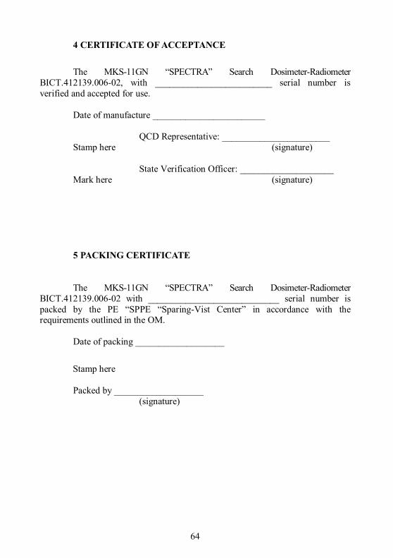
4 CERTIFICATE OF ACCEPTANCE
The MKS-11GN “SPECTRA” Search Dosimeter-Radiometer
ВIСТ.412139.006-02, with _________________________ serial number is verified and accepted for use.
Date of manufacture ________________________ QCD Representative: _______________________ Stamp here (signature) State Verification Officer: ____________________ Mark here (signature) 5 PACKING CERTIFICATE
The MKS-11GN “SPECTRA” Search Dosimeter-Radiometer ВIСТ.412139.006-02 with ____________________________ serial number is packed by the PE “SPPE “Sparing-Vist Center” in accordance with the requirements outlined in the OM.
Date of packing ___________________
Stamp here Packed by ___________________
(signature)

65
6 WARRANTY
6.1 The producer enterprise guarantees the conformity of the dosimeter with the technical requirements provided that the customer observes the guidelines on its use, shipping and storage presented in the OM ВIСТ.412139.006-02 НЕ.
6.2 The warranty period of the dosimeter shall terminate and be of no further effect in 24 months after the date of putting it into operation or after the warranty period of storage terminates.
6.3 The warranty period of storage of the dosimeter is 6 months after its manufacture date according to GOST 27451-87 standard.
6.4 The warranty period of use of the dosimeter is prolonged for the warranty repair period.
6.5 When the warranty period of the dosimeter terminates, the repair is done according to separate agreements.
6.6 Warranty and post-warranty repair is done only by the producer enterprise.
6.7 If the mechanical damage is detected or the seals are removed, the repair is done at customer’s cost.

66
7 REPAIR
7.1 In case of failure or troubles during the warranty period of the dosimeter, the user should contact the supplier in his/her country. Warranty and post-warranty repair should be done only by the producer enterprise at the following address:
PE “SPPE “Sparing-Vist Center”
79026, Ukraine, Lviv, 33 Volodymyr Velyky
Tel.: (+38032) 242 15 15, fax: (+38032) 242 20 15
E-mail: [email protected].
7.2 All claims are registered in Table 7.1.
Table 7.1 Date of failure Claim summary Action taken Note
7.3 Information on repair of the dosimeter is recorded in the table of
Appendix B of this OM.

67
8 STORAGE 8.1 The dosimeters should be stored in the packing box under conditions
1 (Л) according to GOST 15150-69 in heated and ventilated storehouses with air-conditioning at the ambient air temperature from +5 to +40 оС and relative humidity up to 80 % at +25 оС temperature, non-condensing. The storehouse should be free of acids, alkalis and gases that may cause corrosion, and vapors of organic solvents.
8.2 The location of the dosimeters in the storehouses should ensure their free movement and access to them.
8.3 The dosimeters should be stored on the shelves. 8.4 The distance between the walls, the floor of the storehouse and
dosimeters should be at least 1 m. 8.5 The distance between the heating gadgets of the storehouse and the
dosimeters should be at least 0.5 m. 8.6 The average shelf life is not less than six years. 8.7 Additional information on storage, check during storage and
maintenance of the dosimeter is registered in Appendices C, D, E of this OM.
9 SHIPPING
9.1 Packed dosimeters may be shipped by any kinds of closed transport vehicles under the conditions 4 (Ж2) with temperature limitations in the range of – 25 оС to +50 оС according to GOST 15150-69 and rules and standards effective for each means of transport.
9.2 The dosimeters in shipping containers should be placed and fastened in the vehicle so that their stable position is ensured and shocks (with each other and the sidewalls of the transport) are avoided.
9.3 The dosimeters in shipping container endure: - temperature from -25 to +50 оС; - relative humidity (953) % at 35 оС temperature; - shocks effect with 98 m/s2 acceleration, shock pulse duration – 16 ms
and the number of shocks not less than 1000. 9.4 Canting is forbidden.
10 DISPOSAL Disposal of the dosimeter is performed in compliance with the general
rules, i.e. metal is recycled or melted, and plastic parts are dumped.
Disposal of the dosimeter is not dangerous for the service personnel, and is environmentally friendly.

68
APPENDIX А
TROUBLE RECORD DURING USE D
ate
and
time
of fa
ilure
. O
pera
ting
mod
e
Type
(man
ifesta
tion)
of
troub
le
Cau
se o
f tro
uble
, num
ber o
f op
erat
ion
hour
s of t
he fa
iled
el
emen
t
Act
ion
take
n an
d cl
aim
not
e
Posi
tion,
nam
e an
d sig
natu
re o
f th
e pe
rson
resp
onsib
le fo
r so
lvin
g th
e pr
oble
m
Not
e

69
APPENDIX B
REPAIR Po
sitio
n, n
ame
and
sign
atur
e of
the
resp
onsib
le p
erso
n
who
ac
cept
ed
afte
r rep
air
who
pe
rfor
med
re
pair
Nam
e of
repa
ir
Type
of
repa
ir
Num
ber
of h
ours
w
orke
d be
fore
re
pair
Nam
e of
th
e re
pair
orga
niza
- tio
n
Dat
e of re
pair
com
plet
ion
of a
rrivi
ng
for r
epai
r
Reas
on fo
r re
pair
Nam
e an
d ty
pe o
f th
e co
mpo
nent
pa
rt of
the
dosim
eter

70
APPENDIX C
STORAGE
Date
Storage conditions
Position, name and signature of the responsible
person
of placing in storage
of removing from storage

71
APPENDIX D
PUTTING IN PROLONGED STORAGE AND REMOVAL FROM
STORAGE
Date of putting in prolonged storage
Storage method
Date of removal
from prolonged
storage
Name of the enterprise in
charge of putting or removing from prolonged storage
Date, position and signature of the responsible
person

72
APPENDIX E
VERIFICATION AND INSPECTION RESULTS
Date Verification or inspection type
Verification or inspection result
Position, name and signature of
the person responsible for
inspection
Not
e