Embed Size (px)
Citation preview
M.J. Barnes 1
MKI Magnet Design, PT100 Sensor Locations & Heating Observations in 2011
M.J. BarnesAcknowledgements:
H. Day, L. Ducimetiere, N. Garrel
23 November 2011
M.J. Barnes 2
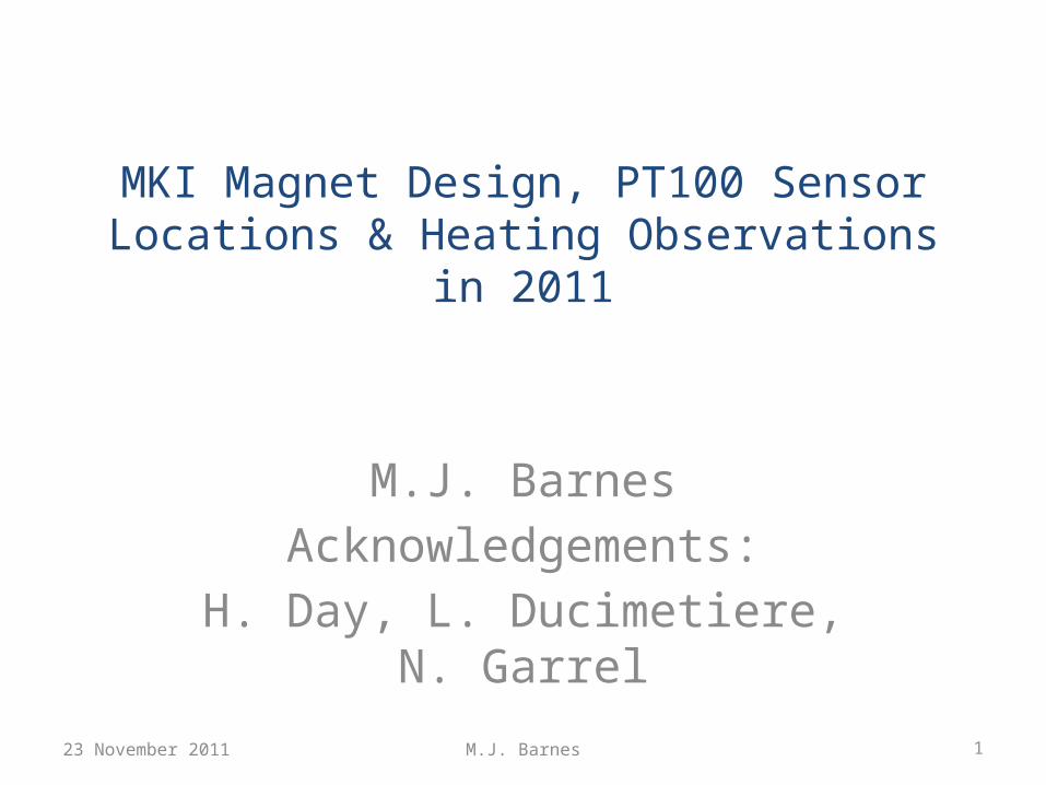
Kicked Beam
TMR connection
entrance box connection
capacitor
ferrite yoke
ground plateground
plate HV plate HV plate
PT100Tube_Dn
Beam impedance reduction ferrite
(lossy + low-loss)
Beam impedance reduction ferrites
(lossy + low-loss)
Damping resistor (now at both ends)
PT100Mag_Dn
PT100Tube_Up
PT100Mag_Up
PT100Tube_Dn
PT100Mag_Dn
PT100Tube_UpPT100
Mag_Up
Screen conductors soldered to “ground”
Screen conductors capacitively coupled to “ground”
An LHC Injection Kicker
23 November 2011
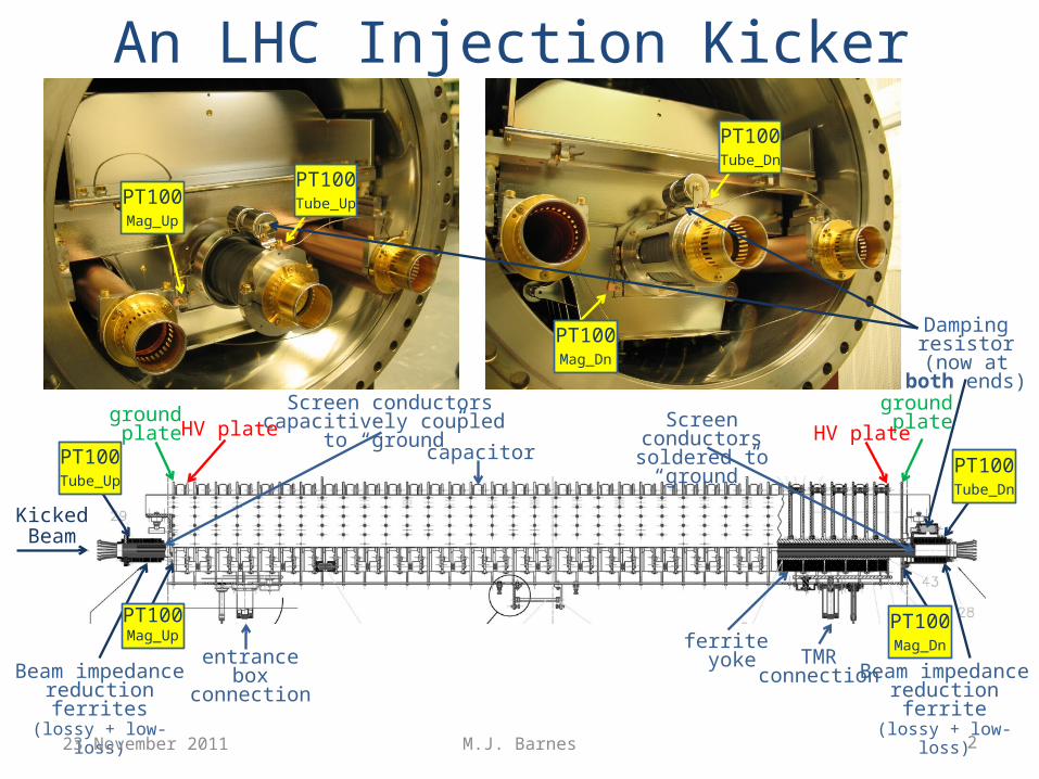
LHC Injection Kicker: Maximum Temperatures During Oct. 2011
Magnet PT100’s are mounted on ground plates: these plates contact the ground busbar and magnet capacitors; Ground busbar does not contact ferrites – hence heat conduction to magnet PT100’s is mainly via magnet capacitors. Hence Mag_Up would be expected to measure a higher temperature than Mag_Dn, but …. Tube_Up temperature > Tube_Dn temperature, maybe because of more cooling at “Dn” end (due to SS tube and “cage” around ferrites??).The Power (W/m) shown is derived from impedance measurements – measured magnet temperature does not correlate with the power….
Kicked Beam
TMR connection
entrance box connection
capacitor
ferrite yoke
ground plateground
plate HV plate
HV plate
PT100Tube_Dn
Beam impedance reduction ferrite
(lossy + low-loss)
Beam impedance reduction ferrites
(lossy + low-loss)
PT100Mag_Dn
PT100Tube_Up
PT100Mag_Up
Screen conductors soldered to “ground”
(Ferrites mounted on SS tube)
Screen conductors capacitively coupled to “ground”
(metallization on ceramic tube)
NO Capacitor
here
23 November 2011 3M.J. Barnes
MKI2 Mag_Up Mag_Dn Tube_Up Tube_Dn Tank Power (W/m)A 42.2 38.8 76 51.1 8 60B 44.1 40.9 70.3 50.2 10 97C 38.8 41.6 66.5 58.6 4 76D NC NC NC NC 9 89
MKI8 Mag_Up Mag_Dn Tube_Up Tube_Dn Tank Power (W/m)A 36.6 NC 73.1 35.4 1 88B 40.9 57.7 88.3 56.7 3 Not meas.C 45.2 40.9 102.1 64.7 2 Not meas.D 43.1 68.3 72.4 67.9 6 Not meas.
M.J. Barnes 4
y = 7.39E-10x + 2.04E-07R² = 9.98E-01
y = 3.79E-09x + 3.25E-07R² = 1.00E+00
6.00E-07
6.10E-07
6.20E-07
6.30E-07
6.40E-07
6.50E-07
6.60E-07
6.70E-07
6.80E-07
6.90E-07
7.00E-07
7.10E-07
2.580E-07
2.600E-07
2.620E-07
2.640E-07
2.660E-07
2.680E-07
2.700E-07
2.720E-07
2.740E-07
2.760E-07
2.780E-07
2.800E-07
75 77.5
80 82.5
85 87.5
90 92.5
95 97.5
100
50%
Del
ay (s
)
TMR
Volt
age
Rise
Tim
e (s
)
Magnet Inductance Scale Value (%)
Predicted 5% to 95% rise-time versus magnet Inductance
RISE_TIMEC(V(MagOut)*50kV/250,1.25k,23.75kV)
XVALUE_AT_YV(V(MagOut)*50k/250,12.5k)-XVALUE_AT_YV(V(MagIn)*50k/250,12.5k)
Terminating Resistor
Transmission Line
Z
Magnet
Z
Z
Main Switch
PFN or PFL
Z
RCPS
Dump Switch
Dump ResistorZ
LcLc
Cc/2Cc/2Cc/2
Lc
Cc/2Cc/2
Lc
Cc/2Cc/2
0
Cc/2
(#1) (#2) (#n)(#[n-1])
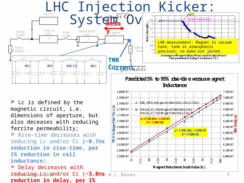
LHC Injection Kicker: System Overview
Lc is defined by the magnetic circuit, i.e. dimensions of aperture, but also deceases with reducing ferrite permeability; Rise-time decreases with reducing Lc and/or Cc (~0.7ns reduction in rise-time, per 1% reduction in cell inductance). Delay decreases with reducing Lc and/or Cc (~3.8ns reduction in delay, per 1% reduction in cell inductance).
Delay m n Lc Cc
1
4cf
Lc Ls Cc
TMR Current
23 November 2011
0
0.5
1
1.5
2
2.5
3
3.5
4
85 90 95 100 105 110 115 120 125 130 135 140 145
Ind
uc
tan
ce
(μH
)
Average of Magnet Input Face and Output Face Temperature During Cool down (˚C)
33 cells * 101nH/cell
106˚C
LAB measurement: Magnet in vacuum tank; tank at atmospheric pressure; no bake-out jacket.
M.J. Barnes 5
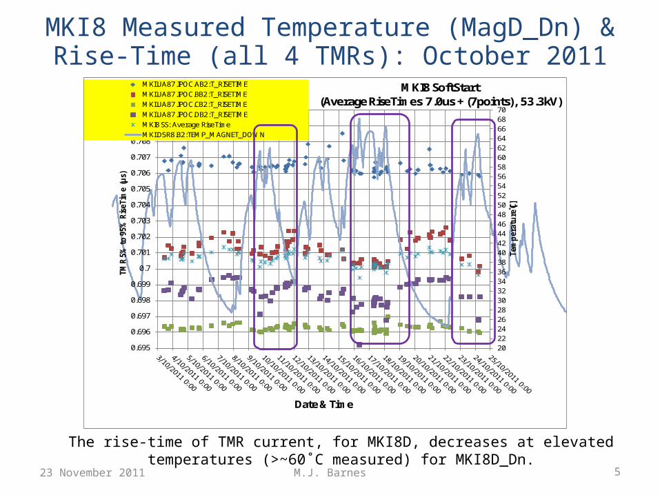
MKI8 Measured Temperature (MagD_Dn) & Rise-Time (all 4 TMRs): October 2011
2022242628303234363840424446485052545658606264666870
0.695
0.696
0.697
0.698
0.699
0.7
0.701
0.702
0.703
0.704
0.705
0.706
0.707
0.708
0.709
0.71
Tem
per
atu
re [˚C
]
TMR
5%
to
95%
Ris
eTim
e (µ
s)
Date & Time
MKI8 SoftStart (Average RiseTimes 7.0us + (7points), 53.3kV)
MKI.UA87.IPOC.AB2:T_RISETIMEMKI.UA87.IPOC.BB2:T_RISETIMEMKI.UA87.IPOC.CB2:T_RISETIMEMKI.UA87.IPOC.DB2:T_RISETIMEMKI8 SS: Average RiseTimeMKI.D5R8.B2:TEMP_MAGNET_DOWN
The rise-time of TMR current, for MKI8D, decreases at elevated temperatures (>~60˚C measured) for MKI8D_Dn.
23 November 2011
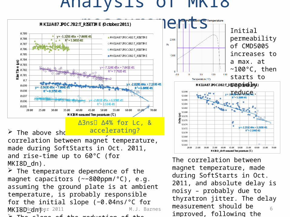
Analysis of MKI8 measurements
y = -2.410E-04x + 5.269E+01R² = 5.360E-01
y = -2.251E-04x + 5.269E+01R² = 2.186E-02
52.664
52.666
52.668
52.670
52.672
52.674
52.676
52.678
52.680
52.682
52.684
52.686
52.688
52.690
20.00 25.00 30.00 35.00 40.00 45.00 50.00 55.00 60.00 65.00 70.00
Del
ay (µ
s)
MKI8-D_dn Measured Temperature (˚C)
MKI.UA87.IPOC.DB2:T_DELAY (October 2011)
The above shows a fairly linear correlation between magnet temperature, made during SoftStarts in Oct. 2011, and rise-time up to 60°C (for MKI8D_dn). The temperature dependence of the magnet capacitors (~−800ppm/°C), e.g. assuming the ground plate is at ambient temperature, is probably responsible for the initial slope (−0.04ns/°C for MKI8D_dn). The slope of the reduction of the rise-time increases above 60°C measured for MKI8D_dn, indicating some of the ferrite yoke is at the Curie temperature.
The correlation between magnet temperature, made during SoftStarts in Oct. 2011, and absolute delay is noisy – probably due to thyratron jitter. The delay measurement should be improved, following the winter TS, by finding the delay w.r.t. thyratron cathode current.
y = -1.325E-05x + 7.069E-01R² = 1.501E-02
y = -7.324E-05x + 7.041E-01R² = 7.792E-01
y = -2.065E-05x + 6.970E-01R² = 3.514E-01
y = -3.563E-05x + 7.004E-01R² = 8.375E-01
y = -2.828E-04x + 7.153E-01R² = 6.809E-01
0.695
0.696
0.697
0.698
0.699
0.7
0.701
0.702
0.703
0.704
0.705
0.706
0.707
0.708
0.709
20.00 25.00 30.00 35.00 40.00 45.00 50.00 55.00 60.00 65.00 70.00
Rise
Tim
e (µ
s)
MKI8 Measured Temperature (˚C)
MKI.UA87.IPOC.?B2:T_RISETIME (October 2011)
MKI.UA87.IPOC.AB2:T_RISETIME
MKI.UA87.IPOC.BB2:T_RISETIME
MKI.UA87.IPOC.CB2:T_RISETIME
MKI.UA87.IPOC.DB2:T_RISETIME
Δ3ns Δ4% for Lc, & accelerating?
23 November 2011 6M.J. Barnes
Initial permeability of CMD5005 increases to a max. at ~100°C, then starts to rapidly reduce.
M.J. Barnes 7
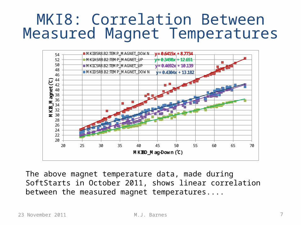
MKI8: Correlation Between Measured Magnet Temperatures
y = 0.6415x + 8.7734y = 0.3498x + 12.651y = 0.4692x + 10.139y = 0.4304x + 13.182
202224262830323436384042444648505254
20 25 30 35 40 45 50 55 60 65 70
MKI
8_M
agne
t (˚C
)
MKI8D_Mag-Down (˚C)
MKI.B5R8.B2:TEMP_MAGNET_DOWNMKI.A5R8.B2:TEMP_MAGNET_UPMKI.C5R8.B2:TEMP_MAGNET_UPMKI.D5R8.B2:TEMP_MAGNET_DOWN
The above magnet temperature data, made during SoftStarts in October 2011, shows linear correlation between the measured magnet temperatures....
23 November 2011
M.J. Barnes 8
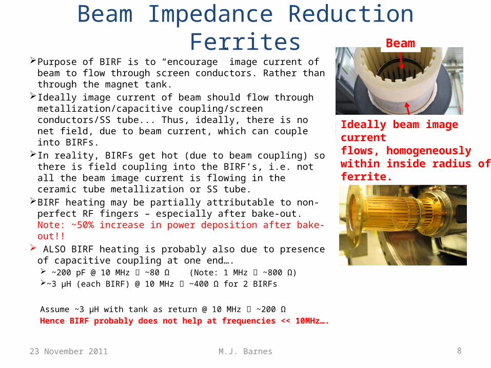
Beam Impedance Reduction Ferrites Purpose of BIRF is to “encourage” image current of beam to
flow through screen conductors. Rather than through the magnet tank.
Ideally image current of beam should flow through metallization/capacitive coupling/screen conductors/SS tube... Thus, ideally, there is no net field, due to beam current, which can couple into BIRFs.
In reality, BIRFs get hot (due to beam coupling) so there is field coupling into the BIRF’s, i.e. not all the beam image current is flowing in the ceramic tube metallization or SS tube.
BIRF heating may be partially attributable to non-perfect RF fingers – especially after bake-out. Note: ~50% increase in power deposition after bake-out!!
ALSO BIRF heating is probably also due to presence of capacitive coupling at one end…. ~200 pF @ 10 MHz ~80 Ω (Note: 1 MHz ~800 Ω) ~3 µH (each BIRF) @ 10 MHz ~400 Ω for 2 BIRFs
Assume ~3 µH with tank as return @ 10 MHz ~200 ΩHence BIRF probably does not help at frequencies << 10MHz….
23 November 2011
Beam
Ideally beam image current flows, homogeneously within inside radius of ferrite.

M.J. Barnes 9
Screen Conductors Ceramic has 24 slots for screen
conductors: only 15 installed to decrease probability of HV breakdown. 15 conductors results in ~3x power beam induced power deposition, in the ferrite yoke, in comparison with 24 screen conductors.
Adding spheres to end of screen conductors will reduce electric field strength and, hopefully, allow 24 conductors to be installed.
Alternative idea for beam screen (beam impedance to be investigated by Hugo): connect only 2 of 24 screen conductors to ground, and capacitively couple others to ground reduces peak voltages by ~2……….
BUT: low frequency impedance will increase…..23 November 2011
Connect to beam-pipe ground
+16kV/-9kV
+1kV/-2kV
+27kV/-17kV
+23kV/-14kV
+11kV/-6kV
24 conductors capacitively coupled to beam-pipe ground
Connect to beam-pipe ground
+16kV/-10kV
+16kV/-10kV
+16kV/-10kV
+16kV/-10kV
+16kV/-10kV
+7kV/-13kV
+4kV/-9kV
+6kV/-3kV
+16kV/-10kV
24 conductors capacitively coupled to beam-pipe ground
22 conductors capacitively coupled to beam-pipe ground
M.J. Barnes 10
Conclusions Mag_Up would be expected to measure a higher temperature than
Mag_Dn, because of PT100 position, but this is not always the case…. Tube_Up temperature > Tube_Dn temperature. Measured temperature of MKI8D_Dn reached 68˚C during October. The
slope of the reduction of the rise-time increases above 60°C, measured for MKI8D_Dn, indicating some of the ferrite yoke is above the Curie temperature. Other MKI8’s do not yet show evidence of yoke being at the Curie temperature.
One BIRF measured temperature reached 102°C during October. BIRF (and a portion of ferrite yoke) heating is probably due to both non-perfect RF fingers (especially after bake-out) and the impedance of the capacitive coupling at frequencies << 10MHz.
Alternative beam screen configurations, which should allow 24 (c.f. 15 screen conductors) to be installed, are under consideration. The extra 9 screen conductors would reduce the expected beam induced power deposition by a factor of ~3.
23 November 2011
M.J. Barnes 11
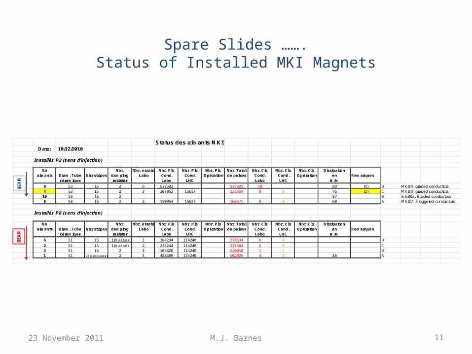
Spare Slides …….Status of Installed MKI Magnets
23 November 2011
Status des aimants MKI Date: 10/12/2010
Installés P2 (sens d'injection)
No aimants Diam. Tube
céramiqueNbr stripes
Nbr.dampingresistor
Nbr. essais Labo
Nbr. Pls Cond. Labo
Nbr. Pls Cond.
LHC
Nbr. Pls Opération
Nbr. Totalde pulses
Nbr. Cls Cond. Labo
Nbr. Cls Cond.
LHC
Nbr. Cls Opération
Dissipationen
W/mRemarques
9 53 15 2 6 537503 537503 40 89 (4) D MKI44. graded conductors4 53 15 2 3 207052 15617 222669 0 0 76 (2) C MKI43. graded conductors
10 53 15 2 97 B mki46a. Graded conductors8 53 15 2 2 150954 15617 166571 0 0 60 A MKI37. Staggered conductors
Installés P8 (sens d'injection)
No aimants Diam. Tube
céramiqueNbr stripes
Nbr.dampingresistor
Nbr. essais Labo
Nbr. Pls Cond. Labo
Nbr. Pls Cond.
LHC
Nbr. Pls Opération
Nbr. Totalde pulses
Nbr. Cls Cond. Labo
Nbr. Cls Cond.
LHC
Nbr. Cls Opération
Dissipationen
W/mRemarques
6 51 15 1(masse) 1 164294 114240 278534 6 0 D
2 51 15 1(masse) 2 223244 114240 337484 6 0 C3 51 15 2 3 105820 114240 220060 1 1 B1 51 24 (9 raccourcis) 2 4 488689 114240 602929 3 0 88 A
BEA
MBE
AM

M.J. Barnes23 November 2011 12
Connect to beam-pipe ground
+16kV/-10kV
+16kV/-10kV
+16kV/-10kV
+16kV/-10kV
+16kV/-10kV
+7kV/-13kV
+4kV/-9kV
+6kV/-3kV
+16kV/-10kV
24 conductors capacitively coupled to beam-pipe ground
22 conductors capacitively coupled to beam-pipe ground
Connect to beam-pipe ground
+16kV/-9kV
+1kV/-2kV
+27kV/-17kV
+23kV/-14kV
+11kV/-6kV
24 conductors capacitively coupled to beam-pipe ground