Embed Size (px)
Citation preview
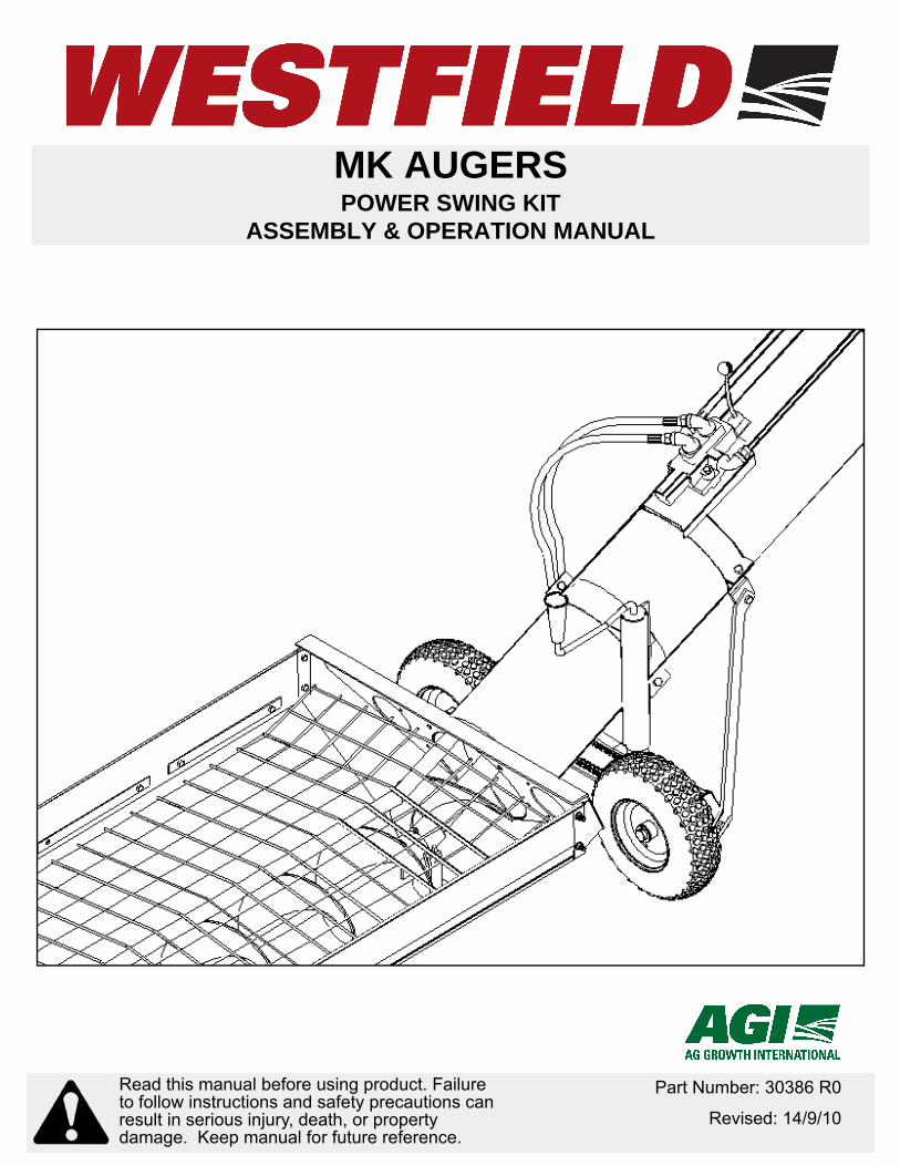
MK AUGERSPOWER SWING KIT
ASSEMBLY & OPERATION MANUAL
Part Number: 30386 R0
Revised: 14/9/10
Read this manual before using product. Failure to follow instructions and safety precautions can result in serious injury, death, or property damage. Keep manual for future reference.

This product has been designed and constructed according to general engineering standardsa. Other local regulations may apply and must be followed by the operator. We strongly recommend that all personnel associated with this equipment be trained in the correct operational and safety procedures required for this product. Periodic reviews of this manual with all employees should be standard practice. For your convenience, we include this sign-off sheet so you can record your periodic reviews.
a. Standards include organizations such as the American Society of Agricultural and Biological Engineers, American National Standards Institute, Canadian Standards Association, International Organization for Standardization, and/or others.
Date Employee Signature Employer Signature

TABLE OF CONTENTS
WESTFIELD - MK AUGERS POWER SWING KIT
1. Safety First............................................................................................................................ 31.1. General Safety ......................................................................................................... 41.2. Assembly Safety....................................................................................................... 51.3. Operational Safety.................................................................................................... 51.4. Maintenance Safety.................................................................................................. 71.5. Hydraulic Safety ....................................................................................................... 71.6. Safety Decal Locations............................................................................................. 7
1.6.1. Decal Installation ........................................................................................ 71.6.2. Decal Locations .......................................................................................... 8
2. Assembly .............................................................................................................................. 92.1. Installation Preparation............................................................................................. 92.2. Axle Assembly.......................................................................................................... 9
2.3.1. Relief Valve (For Closed Center Only) ..................................................... 12
3. Operation ............................................................................................................................ 153.1. Hydraulic Drive ....................................................................................................... 153.2. Operation Procedure .............................................................................................. 16
3.2.1. Transporting ............................................................................................. 16
4. Maintenance & Storage...................................................................................................... 174.1. Maintenance Procedures ....................................................................................... 17
Warranty.................................................................................................................................. 19
30386 R0 1

WESTFIELD - MK AUGERS POWER SWING KIT
2 30386 R0
WESTFIELD - MK AUGERS 1. SAFETY FIRSTPOWER SWING KIT
1. Safety FirstThe Safety Alert symbol to the left identifies important safety messages on the product and in the manual. When you see this symbol, be alert to the possibil-ity of personal injury or death. Follow the instructions in the safety messages. Why is SAFETY important to you?
Three big reasons:
• Accidents disable and kill.• Accidents cost.• Accidents can be avoided.
SIGNAL WORDS
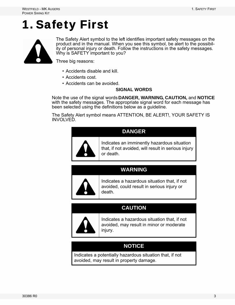
Note the use of the signal words DANGER, WARNING, CAUTION, and NOTICE with the safety messages. The appropriate signal word for each message has been selected using the definitions below as a guideline.
The Safety Alert symbol means ATTENTION, BE ALERT!, YOUR SAFETY IS INVOLVED.
DANGER
Indicates an imminently hazardous situation that, if not avoided, will result in serious injury or death.
WARNING
Indicates a hazardous situation that, if not avoided, could result in serious injury or death.
CAUTION
Indicates a hazardous situation that, if not avoided, may result in minor or moderate injury.
NOTICE
Indicates a potentially hazardous situation that, if not avoided, may result in property damage.
30386 R0 3
1. SAFETY FIRST WESTFIELD - MK AUGERS1.1. GENERAL SAFETY POWER SWING KIT
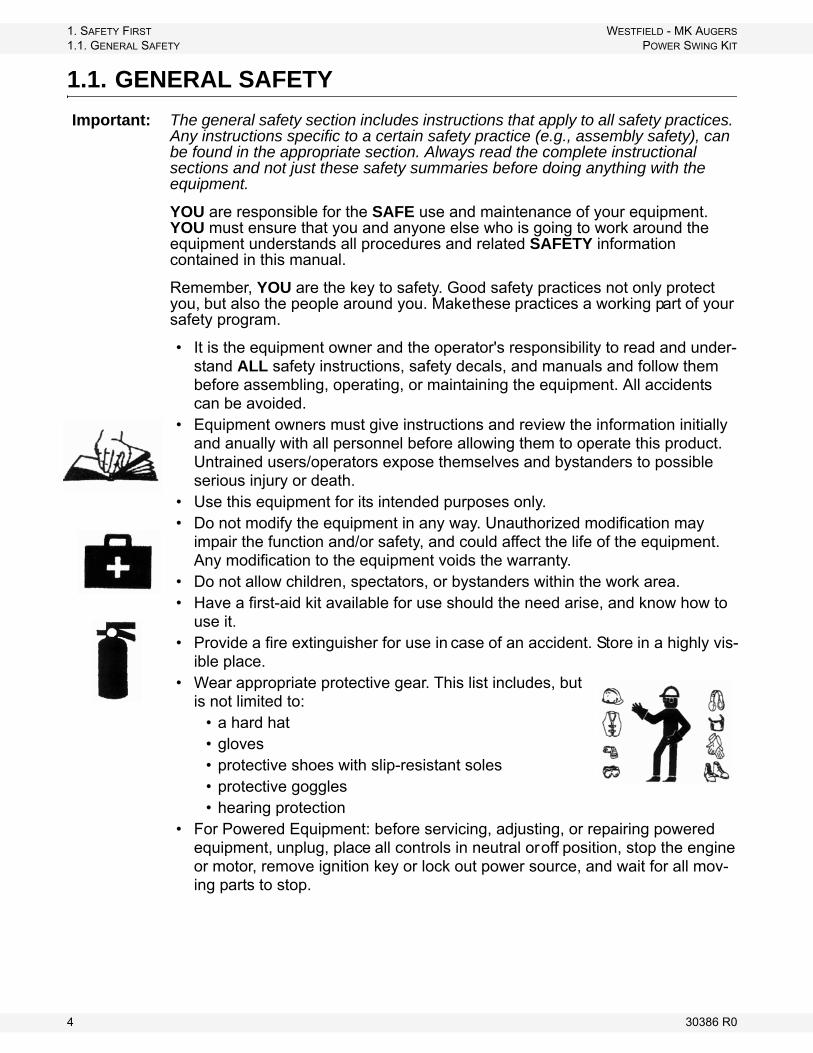
1.1. GENERAL SAFETY
Important: The general safety section includes instructions that apply to all safety practices. Any instructions specific to a certain safety practice (e.g., assembly safety), can be found in the appropriate section. Always read the complete instructional sections and not just these safety summaries before doing anything with the equipment.
YOU are responsible for the SAFE use and maintenance of your equipment. YOU must ensure that you and anyone else who is going to work around the equipment understands all procedures and related SAFETY information contained in this manual.
Remember, YOU are the key to safety. Good safety practices not only protect you, but also the people around you. Make these practices a working part of your safety program.
• It is the equipment owner and the operator's responsibility to read and under-stand ALL safety instructions, safety decals, and manuals and follow them before assembling, operating, or maintaining the equipment. All accidents can be avoided.
• Equipment owners must give instructions and review the information initially and anually with all personnel before allowing them to operate this product. Untrained users/operators expose themselves and bystanders to possible serious injury or death.
• Use this equipment for its intended purposes only.• Do not modify the equipment in any way. Unauthorized modification may
impair the function and/or safety, and could affect the life of the equipment. Any modification to the equipment voids the warranty.
• Do not allow children, spectators, or bystanders within the work area.• Have a first-aid kit available for use should the need arise, and know how to
use it.• Provide a fire extinguisher for use in case of an accident. Store in a highly vis-
ible place.• Wear appropriate protective gear. This list includes, but
is not limited to:• a hard hat• gloves• protective shoes with slip-resistant soles• protective goggles• hearing protection
• For Powered Equipment: before servicing, adjusting, or repairing powered equipment, unplug, place all controls in neutral or off position, stop the engine or motor, remove ignition key or lock out power source, and wait for all mov-ing parts to stop.
4 30386 R0

WESTFIELD - MK AUGERS 1. SAFETY FIRSTPOWER SWING KIT 1.2. ASSEMBLY SAFETY
• Follow good shop practices:• keep service area clean and dry• be sure electrical outlets and tools are properly
grounded• use adequate light for the job at hand• Think SAFETY! Work SAFELY!
1.2. ASSEMBLY SAFETY
• Read through the instructions to get to know the sub-assemblies and hard-ware that make up the equipment.
• Do not take chances with safety. The components are large, heavy, and can be hard to handle. Always use the proper tools, stands, jacks, and hoists for the job.
• Always have 2 or more people assembling the equipment. Because of the weight, do not attempt assembly alone.
1.3. OPERATIONAL SAFETY
• Do not operate with any of the safety guards removed.• Keep body, hair, and clothing away from moving parts. Stay away from intake
during operation.• Do not stand in the path of the Power Swing when it is moving.
Refer to your MK manual for full safety instructions.
30386 R0 5
1. SAFETY FIRST WESTFIELD - MK AUGERS1.3. OPERATIONAL SAFETY POWER SWING KIT
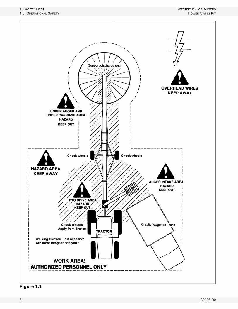
Figure 1.1
6 30386 R0
WESTFIELD - MK AUGERS 1. SAFETY FIRSTPOWER SWING KIT 1.4. MAINTENANCE SAFETY
1.4. MAINTENANCE SAFETY
• Shut down and lock out all power before attempting maintenance of any kind. If applicable, disconnect PTO driveline from tractor or hydraulic hoses on units with hydraulic drive hoppers.
• After maintenance is complete, replace and secure all safety guards and safety devices, and if applicable, service doors and cleanout covers.
• Support auger tube before attempting maintenance on the undercarriage assembly. Auger should be in full down position for maintenance.
• Use only genuine Westfield replacement parts or equivalent. Replacement parts such as intake guards, pulley guards, PTO driveline shields, winches, and lift cables must meet ASABE standards or serious injury may result. Use of unauthorized parts will void warranty. If in doubt, contact Westfield or your Westfield dealer.
• Do not modify any auger components without authorization from Westfield. Modification can be dangerous and result in serious injuries.
1.5. HYDRAULIC SAFETY
• Clean connections before attaching to tractor.• Inspect hydraulic fittings and hoses for damage on a daily basis. Repair if
damaged.• Do not disconnect hydraulic couplers when hydraulic system is pressurized.• Wear proper hand and face protection when searching for hydraulic leaks.
Escaping fluid under pressure can penetrate the skin, causing infection and/or toxic reactor. In case of accident, see a doctor immediately.
• Repair all leaks and breaks in hydraulic valve or hose immediately. Rupture could cause damage and/or personal injury.
1.6. SAFETY DECAL LOCATIONS
• Keep safety decals clean and legible at all times.• Replace safety decals that are missing or have become illegible. See decal
location figures that follow.• Replaced parts must display the same decal(s) as the original part.• Safety decals are available from your distributor, dealer, or factory.
1.6.1. DECAL INSTALLATION
1. Decal area must be clean and dry, with a temperature above 10°C (50°F).2. Decide on the exact position before you remove the backing paper.3. Align the decal over the specified area and carefully press the small portion
with the exposed sticky backing in place.4. Slowly peel back the remaining paper and carefully smooth the remaining
portion of the decal in place.
30386 R0 7

1. SAFETY FIRST WESTFIELD - MK AUGERS1.6. SAFETY DECAL LOCATIONS POWER SWING KIT
5. Small air pockets can be pierced with a pin and smoothed out using the sign backing paper.
1.6.2. DECAL LOCATIONS
Replicas of the safety decals that are attached to the equipment are shown in the figure(s) that follow. Good safety requires that you familiarize yourself with the various safety decals and the areas or particular functions that the decals apply to as well as the safety precautions that must be taken to avoid serious, injury, death, or damage.
* Westfield reserves the right to update safety decals without notice. Safety decals may not be exactly as shown.
DECAL # 17698
8 30386 R0

WESTFIELD - MK AUGERS 2. ASSEMBLYPOWER SWING KIT 2.1. INSTALLATION PREPARATION
2. Assembly
Before starting assembly of your new MK Power Swing, please read the following instructions carefully and familiarize yourself with all the sub-assem-blies and hardware. Arrange all parts for easy access during assembly. Assemble equipment in an open area with a level surface.
2.1. INSTALLATION PREPARATION
1. With auger attached to tractor, park auger on level ground. Lower auger to full down position.
2. Lower swing hopper fully to ground and swing it out onto a level surface.3. Shut down and lock out tractor power.
2.2. AXLE ASSEMBLY
Figure 2.1
Warning: Before continuing, please reread the safety information relevant to this section in the safety section of this manual. Failure to follow the safety instructions can result in serious injury, death, or property damage.
WHEEL ADJUST PLATEWHEEL ADJUSTMENT PLATE
FOR MK130
FOR MK80
FOR MK100AXLE ASSEMBLY
SHOWN WITHOUT GUARDS
30386 R0 9

2. ASSEMBLY WESTFIELD - MK AUGERS2.2. AXLE ASSEMBLY POWER SWING KIT
Figure 2.2
1. Attach lower plate of the jack assembly to the axle using two 7/16” x 1" bolts and locknuts as shown in Figure 2.1 and 2.2. Remove chain guard for easier attachment to the jack. Replace and secure the guard.
2. Loosely attach stabilizer arms to axle assembly using two 7/16” x 1" bolts and locknuts.
• For the MK100 and MK130 series, stabilizer arms attach to the outside of axle end plates.
• For the MK80 series, stabilizer arms attach to the inside of axle end plates.
LONG HYDRAULIC HOSE
HOSE CLIP BRACKET
CONTROL VALVE
VALVE BRACKET
HALF CLAMP
STABILIZER BRACKET
JACK BRACKET
JACK ASSEMBLYUPPER PLATE
HALF CLAMP
SHORT HYDRAULIC HOSE
STABILIZER ARM
CHAIN GUARD
AXLE END PLATE
DRIVE CHAIN
HYDRAULIC MOTOR
INTER-WHEEL DRIVE CHAIN
SPROCKET GUARD
STABILIZER ARM
7/16” X 1” BOLTS & LOCKNUTS
7/16” X 1” BOLTS & LOCKNUTS
7/16” X 1” BOLTS
7/16” LOCKNUTS
10 30386 R0

WESTFIELD - MK AUGERS 2. ASSEMBLYPOWER SWING KIT 2.3. TUBE ASSEMBLY
2.3. TUBE ASSEMBLY
1. Place jack bracket with half clamp onto tube, close to where the end of swing tube joins with the hopper (see Table 2.1). Loosely secure these half-rings with two 7/16” x 1" bolts and locknuts. Position ring so that the jack bracket is vertical to the safety decal on top (Figure 2.3).
2. Adjust jack to approximately 1" above its lowest setting. Attach the jack to the jack bracket using the correct hole in upper plate as shown in Figure 2.3. Use a 1/2” x 1" bolt and locknut and tighten only enough to allow the jack to pivot.
3. Allowing wheels to touch the ground, slide the jack bracket close to the measurement “A” indicated in Table 2.1. Tighten the jack bracket with half clamp in place.
4. Loosely attach other end of the stabilizer arms to stabilizer bracket. Secure the control valve to the valve bracket using three 5/16” x 1-3/4” bolts and locknuts. Then secure this control valve assembly to the swing tube using two 7/16” x 1" bolts and locknuts. Before tightening, adjust the stabilizer bracket to dimension “B” shown in Table 2.1.
Table 2.1 Jack and Stabilizer Spacing Dimensions REGULAR HOPPER
A BMK80 15” 8”
MK100 14” 8”MK130 Plus 15” 8”
LOW PROFILE HOPPERA B
MK100 12” 9”MK130 Plus 16” 10”
JACK BRACKET
A
B
AUGER SWING TUBE
STABILIZER BRACKET
VALVE BRACKET
TO MAIN AUGER
Figure 2.3
30386 R0 11
2. ASSEMBLY WESTFIELD - MK AUGERS2.3. TUBE ASSEMBLY POWER SWING KIT
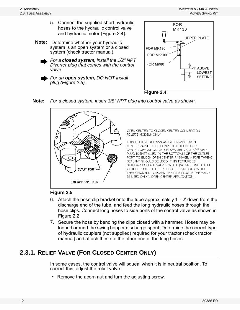
5. Connect the supplied short hydraulic hoses to the hydraulic control valve and hydraulic motor (Figure 2.4).
Determine whether your hydraulic system is an open system or a closed system (check tractor manual).
For a closed system, install the 1/2” NPT Diverter plug that comes with the control valve.
For an open system, DO NOT install plug (Figure 2.5).
Note: For a closed system, insert 3/8” NPT plug into control valve as shown.
Figure 2.5
6. Attach the hose clip bracket onto the tube approximately 1' - 2' down from the discharge end of the tube, and feed the long hydraulic hoses through the hose clips. Connect long hoses to side ports of the control valve as shown in Figure 2.2.
7. Secure the hose by bending the clips closed with a hammer. Hoses may be looped around the swing hopper discharge spout. Determine the correct type of hydraulic couplers (not supplied) required for your tractor (check tractor manual) and attach these to the other end of the long hoses.
2.3.1. RELIEF VALVE (FOR CLOSED CENTER ONLY)
In some cases, the control valve will squeal when it is in neutral position. To correct this, adjust the relief valve:
• Remove the acorn nut and turn the adjusting screw.
UPPER PLATE
~1” ABOVE LOWEST SETTING
FOR MK130
FOR MK130
FOR MK100
FOR MK80
Figure 2.4
Note:
12 30386 R0
WESTFIELD - MK AUGERS 2. ASSEMBLYPOWER SWING KIT 2.3. TUBE ASSEMBLY
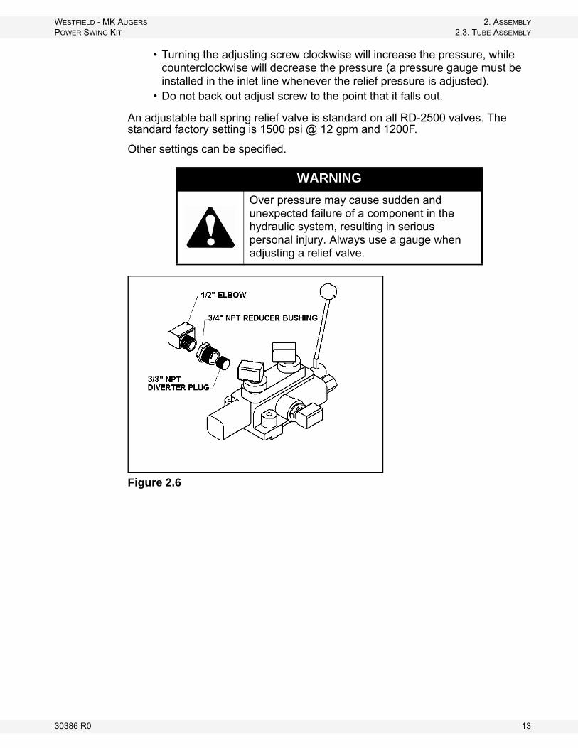
• Turning the adjusting screw clockwise will increase the pressure, while counterclockwise will decrease the pressure (a pressure gauge must be installed in the inlet line whenever the relief pressure is adjusted).
• Do not back out adjust screw to the point that it falls out.
An adjustable ball spring relief valve is standard on all RD-2500 valves. The standard factory setting is 1500 psi @ 12 gpm and 1200F.
Other settings can be specified.
Figure 2.6
WARNING
Over pressure may cause sudden and unexpected failure of a component in the hydraulic system, resulting in serious personal injury. Always use a gauge when adjusting a relief valve.
30386 R0 13

2. ASSEMBLY WESTFIELD - MK AUGERS2.3. TUBE ASSEMBLY POWER SWING KIT
14 30386 R0
WESTFIELD - MK AUGERS 3. OPERATIONPOWER SWING KIT 3.1. HYDRAULIC DRIVE
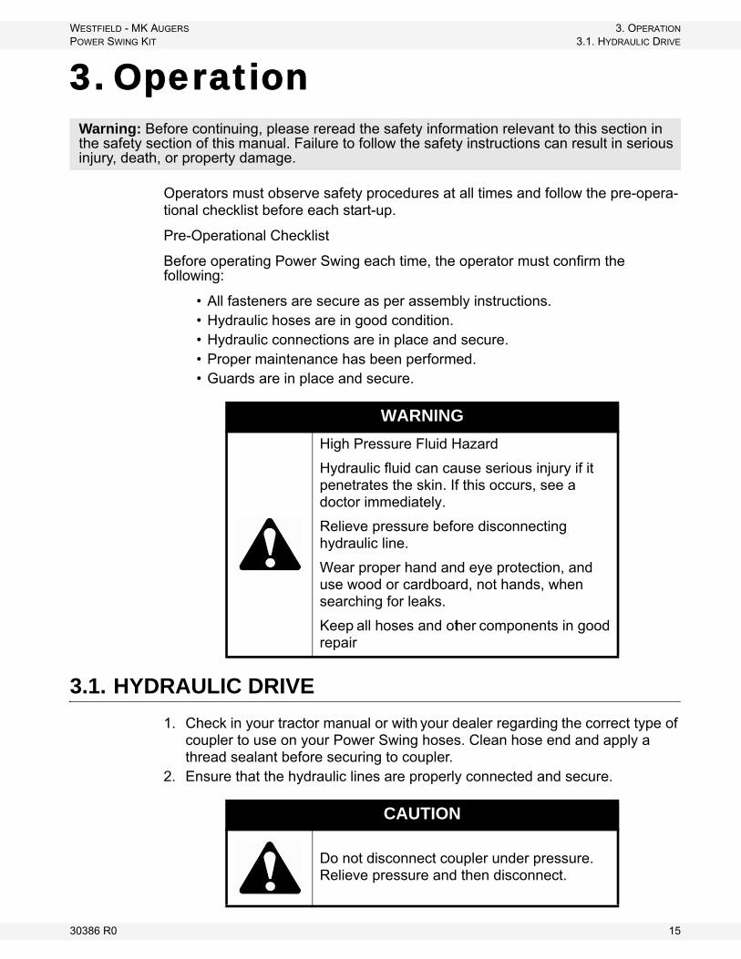
3. Operation
Operators must observe safety procedures at all times and follow the pre-opera-tional checklist before each start-up.
Pre-Operational Checklist
Before operating Power Swing each time, the operator must confirm the following:
• All fasteners are secure as per assembly instructions.• Hydraulic hoses are in good condition.• Hydraulic connections are in place and secure.• Proper maintenance has been performed.• Guards are in place and secure.
3.1. HYDRAULIC DRIVE
1. Check in your tractor manual or with your dealer regarding the correct type of coupler to use on your Power Swing hoses. Clean hose end and apply a thread sealant before securing to coupler.
2. Ensure that the hydraulic lines are properly connected and secure.
Warning: Before continuing, please reread the safety information relevant to this section in the safety section of this manual. Failure to follow the safety instructions can result in serious injury, death, or property damage.
WARNING
High Pressure Fluid Hazard
Hydraulic fluid can cause serious injury if it penetrates the skin. If this occurs, see a doctor immediately.
Relieve pressure before disconnecting hydraulic line.
Wear proper hand and eye protection, and use wood or cardboard, not hands, when searching for leaks.
Keep all hoses and other components in good repair
CAUTION
Do not disconnect coupler under pressure.Relieve pressure and then disconnect.
30386 R0 15

3. OPERATION WESTFIELD - MK AUGERS3.2. OPERATION PROCEDURE POWER SWING KIT
3. Keep hydraulic lines away from moving parts.4. Do not disconnect the hydraulic couplers when under pressure. Consult the
tractor manual for the correct procedure.Important: Because the Power Swing has a control valve independent of the tractor, the
tractor hydraulic control has to be engaged when you are using the Power Swing.
3.2. OPERATION PROCEDURE
1. Engage the tractor hydraulic control; lock it open.2. Lower the Power Swing wheels until they make firm contact with the ground.3. Engage the Power Swing; if you experience loss of traction, adjust the down
pressure of the wheels using the jack.4. After positioning the hopper, adjust the level of the Power Swing to ensure
that the intake hopper is level (so as to not place too much weight on the Power Swing assembly).
5. Keep path of the Power Swing clear of any obstructions.
3.2.1. TRANSPORTING
When transporting the auger, be sure to use the provided saddle pin to lock the swing hopper to the bracket. Since the Power Swing adds more weight to the swing hopper, extra caution is needed when transporting your auger.
Important: The INTAKE FEED side of swing hopper must face main auger when in transport. Do not operate auger with hopper in transport position. This will damage the u-joint.
Important: Read the MK operation manual for further hydraulic safety instructions.
CAUTION
Do not start equipment until area is clear of all untrained personnel.
NOTICE
Hopper must be in transport position when lowering, raising, or moving auger.
16 30386 R0
WESTFIELD - MK AUGERS 4. MAINTENANCE & STORAGEPOWER SWING KIT 4.1. MAINTENANCE PROCEDURES
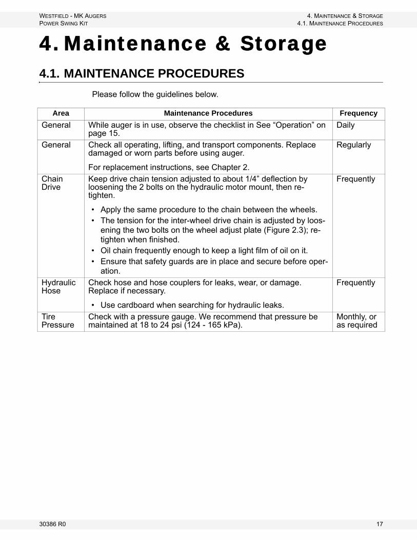
4. Maintenance & Storage4.1. MAINTENANCE PROCEDURES
Please follow the guidelines below.
Area Maintenance Procedures Frequency
General While auger is in use, observe the checklist in See “Operation” on page 15.
Daily
General Check all operating, lifting, and transport components. Replace damaged or worn parts before using auger.
For replacement instructions, see Chapter 2.
Regularly
Chain Drive
Keep drive chain tension adjusted to about 1/4” deflection by loosening the 2 bolts on the hydraulic motor mount, then re-tighten.
• Apply the same procedure to the chain between the wheels. • The tension for the inter-wheel drive chain is adjusted by loos-
ening the two bolts on the wheel adjust plate (Figure 2.3); re-tighten when finished.
• Oil chain frequently enough to keep a light film of oil on it. • Ensure that safety guards are in place and secure before oper-
ation.
Frequently
Hydraulic Hose
Check hose and hose couplers for leaks, wear, or damage. Replace if necessary.
• Use cardboard when searching for hydraulic leaks.
Frequently
Tire Pressure
Check with a pressure gauge. We recommend that pressure be maintained at 18 to 24 psi (124 - 165 kPa).
Monthly, or as required
30386 R0 17

4. MAINTENANCE & STORAGE WESTFIELD - MK AUGERS4.2. STORAGE PROCEDURE POWER SWING KIT
4.2. STORAGE PROCEDURE
TO PROTECT POWER SWING IN STORAGE DURING THE OFF-SEASON:
1. Raise wheels to full up position.2. Clean out axle assembly and lubricate chains with a light coating of oil.3. Inspect unit for damage and note any repairs required. Order replacement
parts from your dealer.4. Check tire pressure and inflate to 24 psi (165 kPa).
TO PREPARE FOR USE AFTER STORAGE:
6. Check tire pressure and inflate according to recommendation on side wall if necessary.
7. Keep decals clean. Replace any decal that is damaged or not clearly visible.8. Conduct general maintenance procedure before using auger.
Important: Use only genuine Westfield replacement parts or equivalent. Replacement parts MUST meet ASABE standards or serious injuries may result. Use of unauthorized parts will void warranty. If in doubt, contact Westfield or your local Westfield dealer. Do not modify any components of the MK Power Swing.
18 30386 R0

WARRANTYWestfield Industries Ltd. warrants products of its manufacture against defects in materials or workmanship under normal and reasonable use for a period of one year after date of delivery to the original purchaser.
Our obligation under this warranty is limited to repairing, replacing, or refunding defective part or parts which shall be returned to a distributor or a dealer of our Company, or to our factory, with transportation charges prepaid. This warranty does not obligate Westfield Industries Ltd. to bear the cost of labor in replacing defective parts. Any defects must be reported to the Company before the end of the one year period.
This warranty shall not apply to equipment which has been altered, improperly assembled, improperly maintained, or improperly repaired so as to adversely affect its performance. Westfield Industries Ltd. makes no express warranty of any character with respect to parts not of its manufacture.
The foregoing is in lieu of all other warranties, expressed or implied, including any warranties that extend beyond the description of the product, and the IMPLIED WARRANTY of MERCHANTABILITY is expressly excluded.
WESTFIELD INDUSTRIES LTD.
ROSENORT, MANITOBA
CANADA
R0G 1W0

Part of the Ag Growth International Inc. Group
P.O. Box 39
Rosenort, Manitoba, Canada R0G 1W0
Phone: (866) 467-7207 (Canada & USA)
Fax: (866) 768-4852
website: www.grainaugers.com
email: [email protected]
© Ag Growth International Inc. 2014
Printed in Canada