Embed Size (px)
Citation preview
mk Factory Equipment
2
„We live our passion for technology –
that shapes us for over 40 years“
Introducing mk
Maschinenbau Kitz GmbH, was
founded in 1966 and is headquar-
tered in Troisdorf, near Bonn,
Germany and operates internatio-
nally together with its subsidia-
ries and sales partners as the “mk
Technology Group”. mk is the
leading supplier of mechanical
modules and components for
profile, conveyor and linear tech-
nology, as well as factory equip-
3
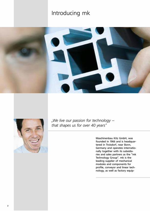
ment. In addition, we are at our
customers' side from the project
planning and design phase, to
implementation, commissioning
and maintenance of complete
transfer systems. The base for the
mk modular system is our variety
of 250 different aluminium profi-
les and comprehensive assembly
and excessively components. The
resulting benefits are conside-
rable cost savings during the in-
stallation of systems as well as a
high degree of flexibility for ex-
tensions and reconstructions. Our
most important target sectors in-
clude the machine construction,
as well as the automotive, electri-
cal, packaging, pharmaceutical,
and food industries.
4
Advantages of the mk modular system
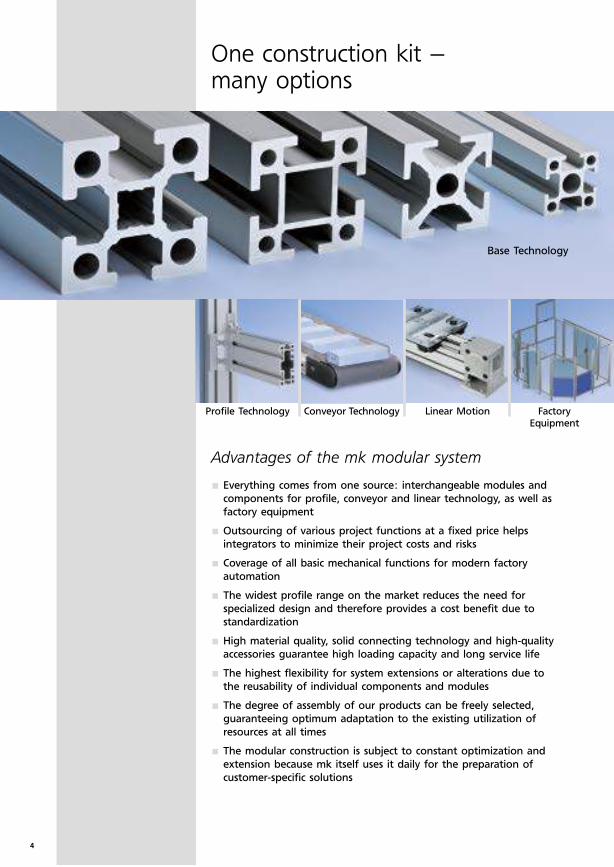
One construction kit – many options
Base Technology
Profile Technology Conveyor Technology Factory Equipment
Linear Motion
Everything comes from one source: interchangeable modules and
components for profile, conveyor and linear technology, as well as
factory equipment
Outsourcing of various project functions at a fixed price helps
integrators to minimize their project costs and risks
Coverage of all basic mechanical functions for modern factory
automation
The widest profi le range on the market reduces the need for
specialized design and therefore provides a cost benefi t due to
standardization
High material quality, solid connecting technology and high-quality
accessories guarantee high loading capacity and long service life
The highest flexibility for system extensions or alterations due to
the reusability of individual components and modules
The degree of assembly of our products can be freely selected,
guaranteeing optimum adaptation to the existing utilization of
resources at all times
The modular construction is subject to constant optimization and
extension because mk itself uses it daily for the preparation of
customer-specific solutions
5
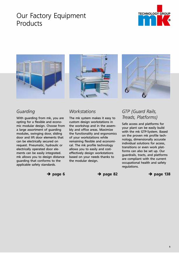
Guarding
With guarding from mk, you are
opting for a flexible and econo-
mic modular design. Choose from
a large assortment of guarding
modules, swinging door, sliding
door and lift door elements that
can be electrically secured on
request. Pneumatic, hydraulic or
electrically operated door ele-
ments can be easily integrated.
mk allows you to design distance
guarding that conforms to the
applicable safety standards.
� è page 6
Workstations
The mk system makes it easy to
custom design workstations in
the workshop and in the assem-
bly and office areas. Maximize
the functionality and ergonomics
of your workstations while
remaining flexible and economi-
cal. The mk profile technology
allows you to easily and cost-
effectively design workstations
based on your needs thanks to
the modular design.
� è page 82
GTP (Guard Rails,
Treads, Platforms)
Safe access and platforms for
your plant can be easily build
with the mk GTP-System. Based
on the proven mk profile tech-
nology, dimensionally accu rate
individual solutions for access,
transitions or even work plat-
forms can also be set up. Our
guardrails, tracts, and platforms
are compliant with the current
occupational health and safety
regulations.
è page 138
Our Factory Equipment Products
6
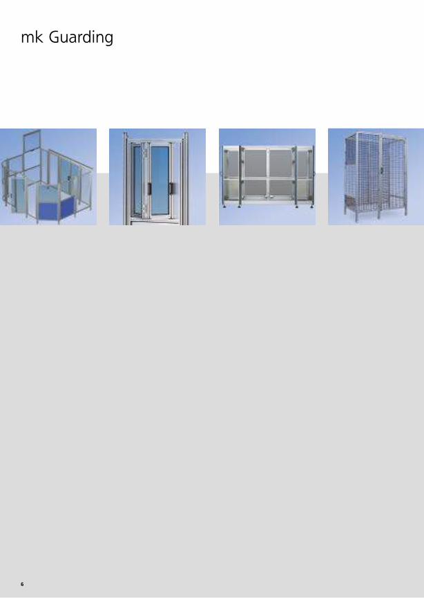
mk Guarding
7
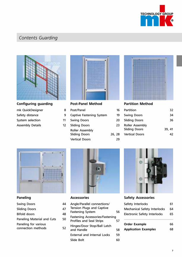
Contents Guarding
Configuring guarding
mk QuickDesigner 8
Safety distance 9
System selection 11
Assembly Details 12
Paneling
Swing Doors 44
Sliding Doors 47
Bifold doors 48
Paneling Material and Cuts 50
Paneling for various
connection methods 52
Post-Panel Method
Post/Panel 16
Captive Fastening System 19
Swing Doors 20
Sliding Doors 23
Roller Assembly
Sliding Doors 26, 28
Vertical Doors 29
Accessories
Angle/Parallel connections/
Tension Plugs and Captive
Fastening System 56
Fastening Accessories/Fastening
Profiles and Seal Strips 57
Hinges/Door Stop/Ball Latch
and Handle 58
External and Internal Locks 59
Slide Bolt 60
Partition Method
Partition 32
Swing Doors 34
Sliding Doors 36
Roller Assembly
Sliding Doors 39, 41
Vertical Doors 42
Safety Accessories
Safety Interlocks 61
Mechanical Safety Interlocks 64
Electronic Safety Interlocks 65
Order Example 66
Application Examples 68
8
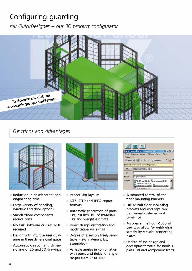
Import .dxf layouts
IGES, STEP and JPEG export
formats
Automatic generation of parts
lists, cut lists, bill of materials
lists and weight estimates
Direct design verification and
modification via e-mail
Degree of assembly freely selec-
table (raw materials, kit,
assembled)
Variable angles in combination
with posts and fields for angle
ranges from 0° to 135°
Reduction in development and
engineering time
Large variety of paneling,
window and door options
Standardized components
reduce costs
No CAD software or CAD skills
required
Design with intuitive user guid-
ance in three dimensional space
Automatic creation and dimen-
sioning of 2D and 3D drawings
Configuring guardingmk QuickDesigner – our 3D product configurator
Automated control of the
floor mounting brackets
Full or half floor mounting
brackets and end caps can
be manually selected and
combined
Post-panel method: Optional
end caps allow for quick disas-
sembly by straight connecting
plates
Update of the design and
development status for models,
parts lists and component limits
Functions and Advantages
To download, click on
www.mk-group.com/Service
9
2600
2400
2200
2000
1800
1600
1400
1200
1000
800
600
400
180
0
2600
2400
2200
2000
1800
1600
1400
1200
1000
800
600
400
180
0
Safety through mk Guarding
Effectively safeguard your plant with mk guarding
systems. Choose from a wide range of guarding
components and build barriers which are precisely
matched to your individual spatial circumstances as
well as the required safety distances of your plant.
In this way you prevent employees or visitors from
entering hazard zones or falling equipment, tools
or workpieces from causing serious accidents.
All mk guarding is designed and produced taking
into account the country-specific relevant safety
standards. So that you are always on the safe side!
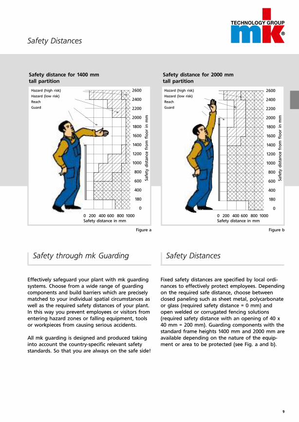
Safety Distances
Fixed safety distances are specified by local ordi-
nances to effectively protect employees. Depending
on the required safe distance, choose between
closed paneling such as sheet metal, poly carbonate
or glass (required safety distance = 0 mm) and
open welded or corrugated fencing solutions
(required safety distance with an opening of 40 x
40 mm = 200 mm). Guarding components with the
standard frame heights 1400 mm and 2000 mm are
available depending on the nature of the equip-
ment or area to be protected (see Fig. a and b).
0 200 400 600 800 1000 Safety distance in mm
Safe
ty d
ista
nce
fro
m f
loor
in m
m
0 200 400 600 800 1000 Safety distance in mm
Safe
ty d
ista
nce
fro
m f
loor
in m
m
Safety distance for 1400 mm
tall partition
Safety distance for 2000 mm
tall partition
Hazard (high risk)
Hazard (low risk)
Reach
Guard
Hazard (high risk)
Hazard (low risk)
Reach
Guard
Figure a Figure b
Safety Distances
10
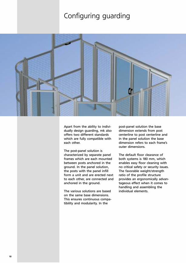
Configuring guarding
Apart from the ability to indivi-
dually design guarding, mk also
offers two different standards
which are fully compatible with
each other.
The post-panel solution is
characterized by separate panel
frames which are each mounted
between posts anchored in the
ground. In the panel solution,
the posts with the panel infill
form a unit and are erected next
to each other, are connected and
anchored in the ground.
The various solutions are based
on the same base dimensions.
This ensures continuous compa-
tibility and modularity. In the
post-panel solution the base
dimension extends from post
centerline to post centerline and
in the panel solution the base
dimension refers to each frame’s
outer dimensions.
The default floor clearance of
both systems is 180 mm, which
enables easy floor cleaning with
no critical safety or security issues.
The favorable weight/strength
ratio of the profile structure
provides an ergonomically advan-
tageous effect when it comes to
handling and assembling the
individual elements.
11
AM = RM-80
RM RM RM
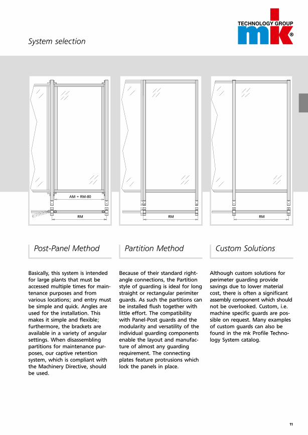
System selection
Post-Panel Method
Basically, this system is intended
for large plants that must be
accessed multiple times for main-
tenance purposes and from
various locations; and entry must
be simple and quick. Angles are
used for the installation. This
makes it simple and flexible;
furthermore, the brackets are
available in a variety of angular
settings. When disassembling
partitions for maintenance pur-
poses, our captive retention
system, which is compliant with
the Machinery Directive, should
be used.
Partition Method
Because of their standard right-
angle connections, the Partition
style of guarding is ideal for long
straight or rectangular perimiter
guards. As such the partitions can
be installed flush together with
little effort. The compatibility
with Panel-Post guards and the
modularity and versatility of the
individual guarding components
enable the layout and manufac-
ture of almost any guarding
requirement. The connecting
plates feature protrusions which
lock the panels in place.
Custom Solutions
Although custom solutions for
perimeter guarding provide
sa vings due to lower material
cost, there is often a significant
assem bly component which should
not be overlooked. Custom, i.e.
machine specific guards are pos-
sible on request. Many examples
of custom guards can also be
found in the mk Profile Techno-
logy System catalog.
12
Assembly Details
Configuring guarding
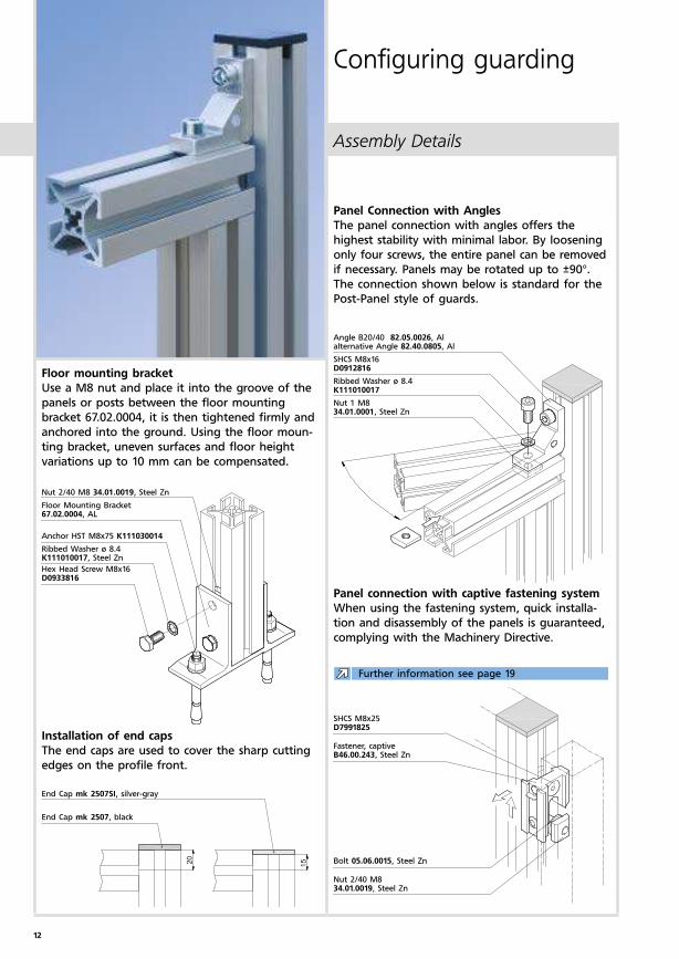
Angle B20/40 82.05.0026, Al alternative Angle 82.40.0805, Al
SHCS M8x16 D0912816
Ribbed Washer ø 8.4 K111010017
Nut 1 M8 34.01.0001, Steel Zn
Nut 2/40 M8 34.01.0019, Steel Zn
Floor Mounting Bracket 67.02.0004, AL
Anchor HST M8x75 K111030014
Ribbed Washer ø 8.4 K111010017, Steel Zn
Hex Head Screw M8x16 D0933816
Panel Connection with Angles
The panel connection with angles offers the
highest stability with minimal labor. By loosening
only four screws, the entire panel can be removed
if necessary. Panels may be rotated up to ±90°.
The connection shown below is standard for the
Post-Panel style of guards.
Floor mounting bracket
Use a M8 nut and place it into the groove of the
panels or posts between the floor mounting
bracket 67.02.0004, it is then tightened firmly and
anchored into the ground. Using the floor moun-
ting bracket, uneven surfaces and floor height
variations up to 10 mm can be compensated.
SHCS M8x25 D7991825
Fastener, captive B46.00.243, Steel Zn
Bolt 05.06.0015, Steel Zn
Nut 2/40 M8 34.01.0019, Steel Zn
End Cap mk 2507SI, silver-gray
End Cap mk 2507, black
Panel connection with captive fastening system
When using the fastening system, quick installa-
tion and disassembly of the panels is guaranteed,
complying with the Machinery Directive.
Installation of end caps
The end caps are used to cover the sharp cutting
edges on the profile front.
Further information see page 19
13
Assembly Details
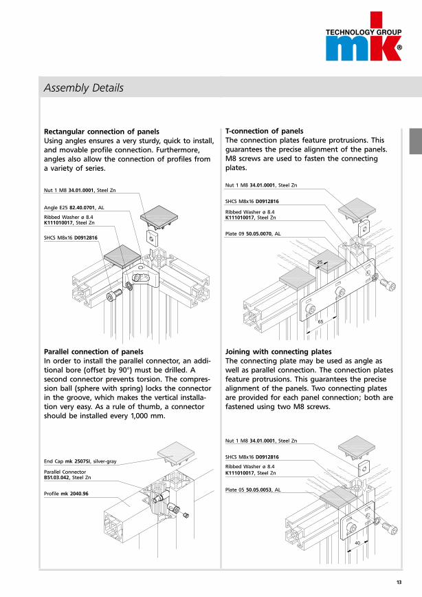
Nut 1 M8 34.01.0001, Steel Zn
SHCS M8x16 D0912816
Ribbed Washer ø 8.4
K111010017, Steel Zn
Plate 05 50.05.0053, AL
Nut 1 M8 34.01.0001, Steel Zn
SHCS M8x16 D0912816
Ribbed Washer ø 8.4 K111010017, Steel Zn
Plate 09 50.05.0070, AL
Nut 1 M8 34.01.0001, Steel Zn
Angle E25 82.40.0701, AL
Ribbed Washer ø 8.4 K111010017, Steel Zn
SHCS M8x16 D0912816
End Cap mk 2507SI, silver-gray
Parallel Connector B51.03.042, Steel Zn
Profile mk 2040.96
Parallel connection of panels
In order to install the parallel connector, an addi-
tional bore (offset by 90°) must be drilled. A
second connector prevents torsion. The compres-
sion ball (sphere with spring) locks the connector
in the groove, which makes the vertical installa-
tion very easy. As a rule of thumb, a connector
should be installed every 1,000 mm.
Joining with connecting plates
The connecting plate may be used as angle as
well as parallel connection. The connection plates
feature protrusions. This guarantees the precise
alignment of the panels. Two connecting plates
are provided for each panel connection; both are
fastened using two M8 screws.
T-connection of panels
The connection plates feature protrusions. This
guarantees the precise alignment of the panels.
M8 screws are used to fasten the connecting
plates.
Rectangular connection of panels
Using angles ensures a very sturdy, quick to install,
and movable profile connection. Furthermore,
angles also allow the connection of profiles from
a variety of series.
14
Assembly Details
Configuring guarding
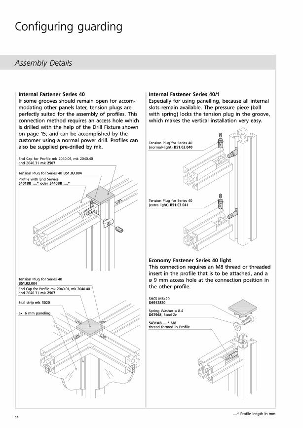
Internal Fastener Series 40
If some grooves should remain open for accom-
modating other panels later, tension plugs are
perfectly suited for the assembly of profiles. This
connection method requires an access hole which
is drilled with the help of the Drill Fixture shown
on page 15, and can be accomplished by the
customer using a normal power drill. Profiles can
also be supplied pre-drilled by mk.
End Cap for Profile mk 2040.01, mk 2040.40 and 2040.31 mk 2507
Tension Plug for Series 40 B51.03.004
Profile with End Service5401BB ....* oder 5440BB ....*
Tension Plug for Series 40 B51.03.004
End Cap for Profile mk 2040.01, mk 2040.40 and 2040.31 mk 2507
Seal strip mk 3020
ex. 6 mm paneling
....* Profile length in mm
Economy Fastener Series 40 light
This connection requires an M8 thread or threaded
insert in the profile that is to be attached, and a
ø 9 mm access hole at the connection position in
the other profile.
Internal Fastener Series 40/1
Especially for using panelling, because all internal
slots remain available. The pressure piece (ball
with spring) locks the tension plug in the groove,
which makes the vertical installation very easy.
SHCS M8x20 D6912820
Spring Washer ø 8.4 D67968, Steel Zn
5431AB ....* M8 thread formed in Profile
Tension Plug for Series 40 (normal+light) B51.03.040
Tension Plug for Series 40 (extra light) B51.03.041
15
M8
M12
x 1
,5
Assembly Details
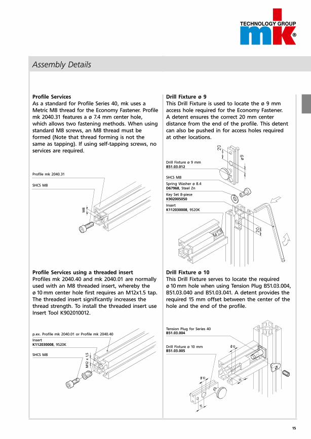
Drill Fixture ø 9
This Drill Fixture is used to locate the ø 9 mm
access hole required for the Economy Fastener.
A detent ensures the correct 20 mm center
distance from the end of the profile. This detent
can also be pushed in for access holes required
at other locations.
Profile Services
As a standard for Profile Series 40, mk uses a
Metric M8 thread for the Economy Fastener. Profile
mk 2040.31 features a ø 7.4 mm center hole,
which allows two fastening methods. When using
standard M8 screws, an M8 thread must be
formed (Note that thread forming is not the
same as tapping). If using self-tapping screws, no
services are required.
Profile Services using a threaded insert
Profiles mk 2040.40 and mk 2040.01 are normally
used with an M8 threaded insert, whereby the
ø 10 mm center hole first requires an M12x1.5 tap.
The threaded insert significantly increases the
thread strength. To install the threaded insert use
Insert Tool K902010012.
Profile mk 2040.31
SHCS M8
Drill Fixture ø 9 mm B51.03.012
SHCS M8
Spring Washer ø 8.4 D67968, Steel Zn
Key Set 8-piece K902005050
Insert K112030008, 9S20K
p.ex. Profile mk 2040.01 or Profile mk 2040.40
Insert K112030008, 9S20K
SHCS M8
Tension Plug for Series 40 B51.03.004
Drill Fixture ø 10 mm B51.03.005
Drill Fixture ø 10
This Drill Fixture serves to locate the required
ø 10 mm hole when using Tension Plug B51.03.004,
B51.03.040 and B51.03.041. A detent provides the
required 15 mm offset between the center of the
hole and the end of the profile.
16
q w e r t y u i
Post-Panel Method
Guarding
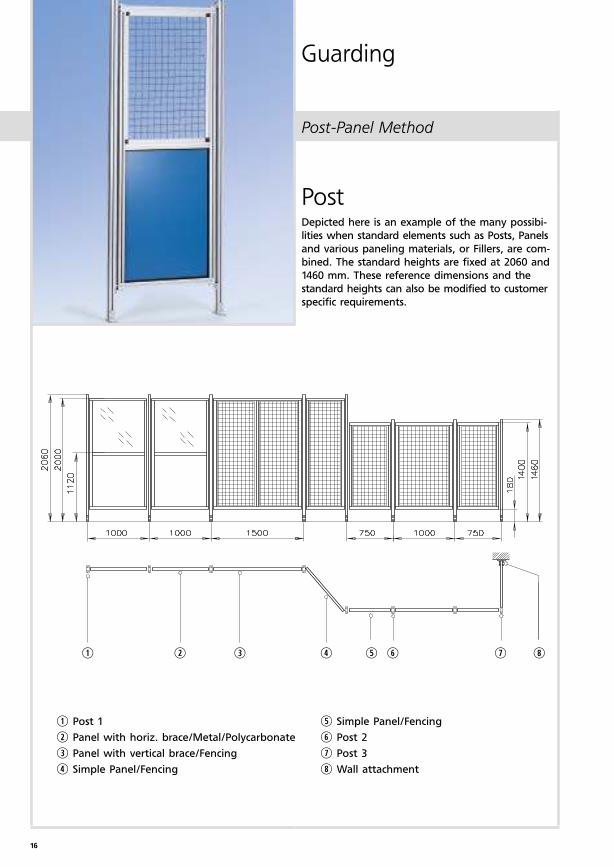
PostDepicted here is an example of the many possi bi-
lities when standard elements such as Posts, Panels
and various paneling materials, or Fillers, are com-
bined. The standard heights are fixed at 2060 and
1460 mm. These reference dimensions and the
standard heights can also be modified to customer
specific requirements.
q Post 1
w Panel with horiz. brace/Metal/Polycarbonate
e Panel with vertical brace/Fencing
r Simple Panel/Fencing
t Simple Panel/Fencing
y Post 2
u Post 3
i Wall attachment
17
Post-Panel Method
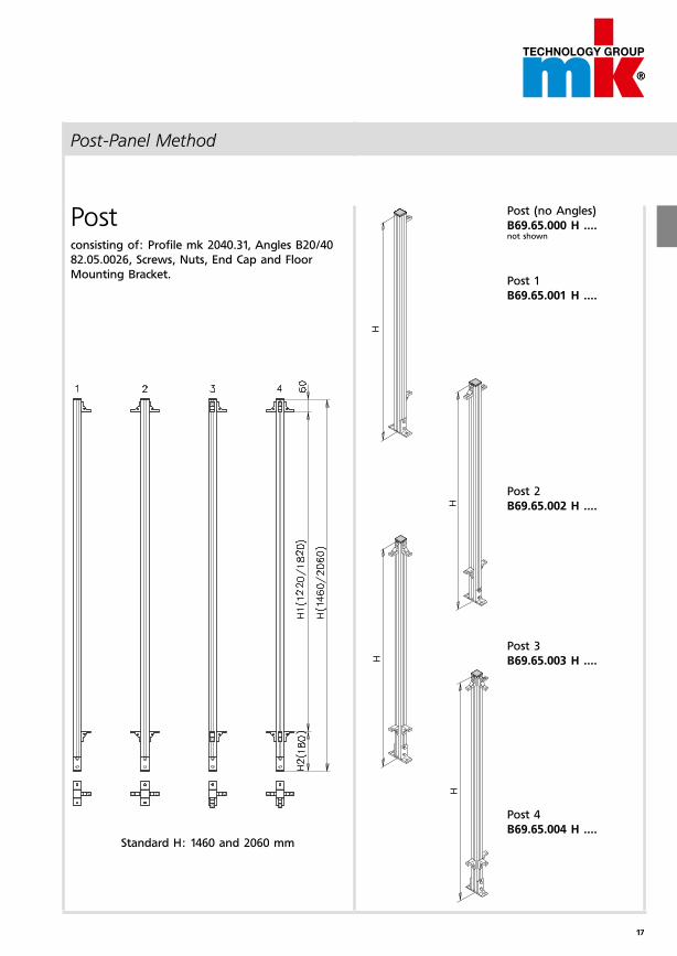
Post (no Angles)
B69.65.000 H ....not shown
Post 1
B69.65.001 H ....
Post 2
B69.65.002 H ....
Post 3
B69.65.003 H ....
Post 4
B69.65.004 H ....
Postconsisting of: Profile mk 2040.31, Angles B20/40
82.05.0026, Screws, Nuts, End Cap and Floor
Mounting Bracket.
Standard H: 1460 and 2060 mm
18
AM
AM
AM
1
1
1
2
2
Post-Panel Method
Guarding
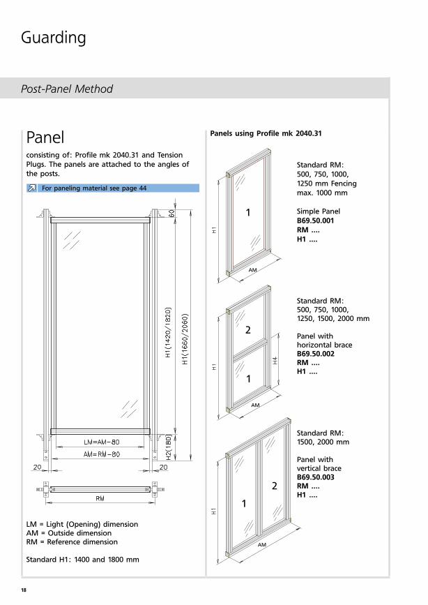
Panels using Profile mk 2040.31Panelconsisting of: Profile mk 2040.31 and Tension
Plugs. The panels are attached to the angles of
the posts.
LM = Light (Opening) dimensionAM = Outside dimensionRM = Reference dimension
Standard H1: 1400 and 1800 mm
Standard RM:
500, 750, 1000,
1250 mm Fencing
max. 1000 mm
Simple Panel
B69.50.001
RM ....
H1 ....
Standard RM:500, 750, 1000, 1250, 1500, 2000 mm
Panel with horizontal braceB69.50.002RM ....H1 ....
Standard RM: 1500, 2000 mm
Panel with vertical braceB69.50.003RM ....H1 ....
For paneling material see page 44
19
Post-Panel Method
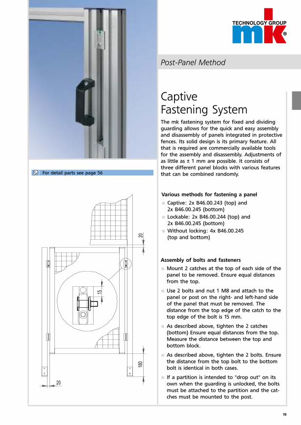
Captive Fastening SystemThe mk fastening system for fixed and dividing
guarding allows for the quick and easy assembly
and disassembly of panels integrated in protective
fences. Its solid design is its primary feature. All
that is required are commercially available tools
for the assembly and disassembly. Adjustments of
as little as ± 1 mm are possible. It consists of
three different panel blocks with various features
that can be combined randomly.For detail parts see page 56
Various methods for fastening a panel
Captive: 2x B46.00.243 (top) and
2x B46.00.245 (bottom)
Lockable: 2x B46.00.244 (top) and
2x B46.00.245 (bottom)
Without locking: 4x B46.00.245
(top and bottom)
Assembly of bolts and fasteners
Mount 2 catches at the top of each side of the
panel to be removed. Ensure equal distances
from the top.
Use 2 bolts and nut 1 M8 and attach to the
panel or post on the right- and left-hand side
of the panel that must be removed. The
distance from the top edge of the catch to the
top edge of the bolt is 15 mm.
As described above, tighten the 2 catches
(bottom) Ensure equal distances from the top.
Measure the distance between the top and
bottom block.
As described above, tighten the 2 bolts. Ensure
the distance from the top bolt to the bottom
bolt is identical in both cases.
If a partition is intended to "drop out" on its
own when the guarding is unlocked, the bolts
must be attached to the partition and the cat-
ches must be mounted to the post.
20
q w e r t y u i o a s
Post-Panel Method
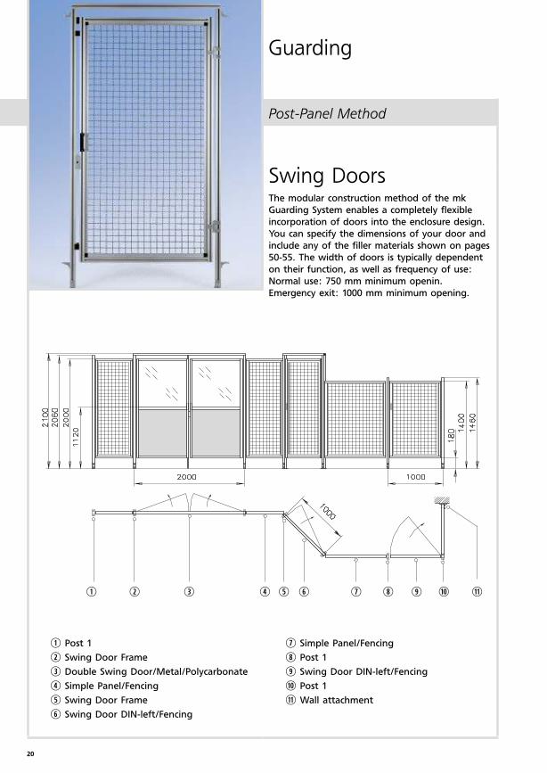
Swing DoorsThe modular construction method of the mk
Guarding System enables a completely flexible
incorporation of doors into the enclosure design.
You can specify the dimensions of your door and
include any of the filler materials shown on pages
50-55. The width of doors is typically dependent
on their function, as well as frequency of use:
Normal use: 750 mm minimum openin.
Emergency exit: 1000 mm minimum opening.
q Post 1
w Swing Door Frame
e Double Swing Door/Metal/Polycarbonate
r Simple Panel/Fencing
t Swing Door Frame
y Swing Door DIN-left/Fencing
u Simple Panel/Fencing
i Post 1
o Swing Door DIN-left/Fencing
a Post 1
s Wall attachment
Guarding
21
RM
RM
AM = RM-40
Post-Panel Method
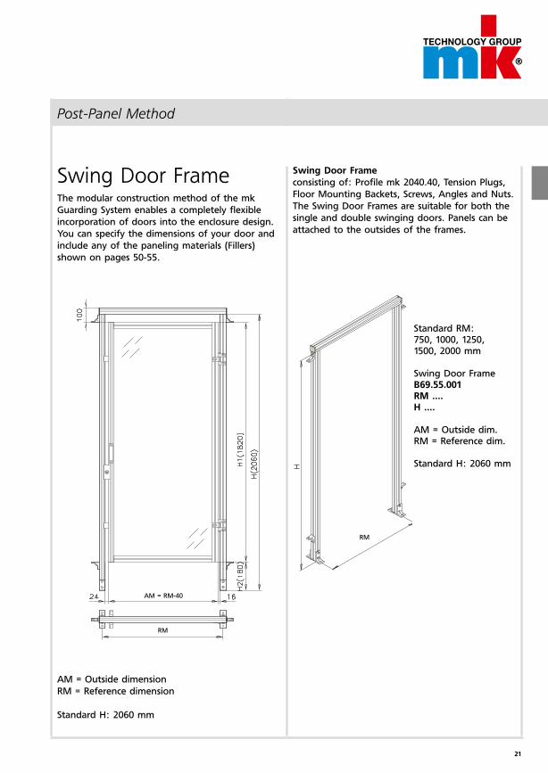
Swing Door Frame
consisting of: Profile mk 2040.40, Tension Plugs,
Floor Mounting Backets, Screws, Angles and Nuts.
The Swing Door Frames are suitable for both the
single and double swinging doors. Panels can be
attached to the outsides of the frames.
Swing Door FrameThe modular construction method of the mk
Guarding System enables a completely flexible
incorporation of doors into the enclosure design.
You can specify the dimensions of your door and
include any of the paneling materials (Fillers)
shown on pages 50-55.
AM = Outside dimension
RM = Reference dimension
Standard H: 2060 mm
Standard RM: 750, 1000, 1250, 1500, 2000 mm
Swing Door FrameB69.55.001RM ....H ....
AM = Outside dim.RM = Reference dim.
Standard H: 2060 mm
22
1
1
2
2
AM =
RM-72
1
AM = RM-72
2
1
2
AM = RM-40
AM = RM-40
1
Post-Panel Method
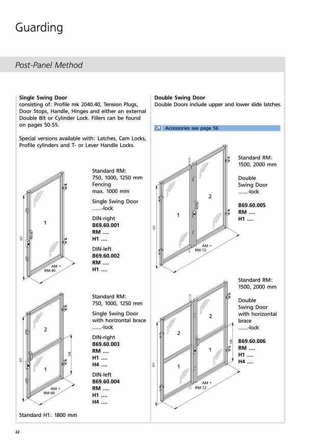
Double Swing Door
Double Doors include upper and lower slide latches.
Single Swing Door
consisting of: Profile mk 2040.40, Tension Plugs,
Door Stops, Handle, Hinges and either an external
Double Bit or Cylinder Lock. Fillers can be found
on pages 50-55.
Special versions available with: Latches, Cam Locks,
Profile cylinders and T- or Lever Handle Locks.
Standard RM:
1500, 2000 mm
Double
Swing Door
......-lock
B69.60.005
RM ....
H1 ....
Standard RM:
1500, 2000 mm
Double
Swing Door
with horizontal
brace
......-lock
B69.60.006
RM ....
H1 ....
H4 ....
Standard RM:
750, 1000, 1250 mm
Fencing
max. 1000 mm
Single Swing Door
......-lock
DIN-right
B69.60.001
RM ....
H1 ....
DIN-left
B69.60.002
RM ....
H1 ....
Standard RM:
750, 1000, 1250 mm
Single Swing Door
with horizontal brace
......-lock
DIN-right
B69.60.003
RM ....
H1 ....
H4 ....
DIN-left
B69.60.004
RM ....
H1 ....
H4 ....
Standard H1: 1800 mm
Guarding
Accessories see page 56
23
q w e r t y u y
2000
1000
1000
2000
4000
210
0
2060
2000
180
Post-Panel Method
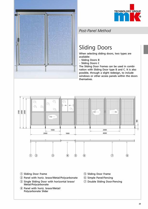
Sliding DoorsWhen selecting sliding doors, two types are
available:
Sliding Doors B
Sliding Doors C
The Sliding Door Frames can be used in combi-
nation with Sliding Door type B and C. It is also
possible, through a slight redesign, to include
windows or other access panels within the doors
themselves.
q Sliding Door Frame
w Panel with horiz. brace/Metal/Polycarbonate
e Single Sliding Door with horizontal brace/ Metal/Polycarbonate
r Panel with horiz. brace/Metal/ Polycarbonate Slider
t Sliding Door Frame
y Simple Panel/Fencing
u Double Sliding Door/Fencing
24
RM
2RM
RM
RM
RM
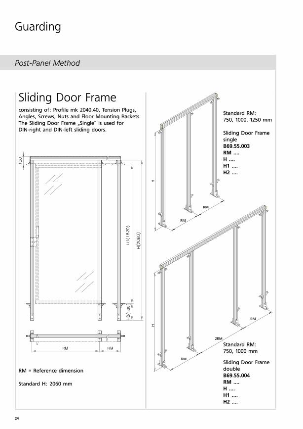
Post-Panel Method
Sliding Door Frameconsisting of: Profile mk 2040.40, Tension Plugs,
Angles, Screws, Nuts and Floor Mounting Backets.
The Sliding Door Frame „Single“ is used for
DIN-right and DIN-left sliding doors.
RM = Reference dimension
Standard H: 2060 mm
Standard RM:
750, 1000 mm
Sliding Door Frame
double
B69.55.004
RM ....
H ....
H1 ....
H2 ....
Standard RM:
750, 1000, 1250 mm
Sliding Door Frame
single
B69.55.003
RM ....
H ....
H1 ....
H2 ....
Guarding
25
AM = RM-22
11
2
2
2
1
1
2
1
AM = RM-22
AM = 2RM+40
AM = 2RM+40
SH
SH
SH
SH
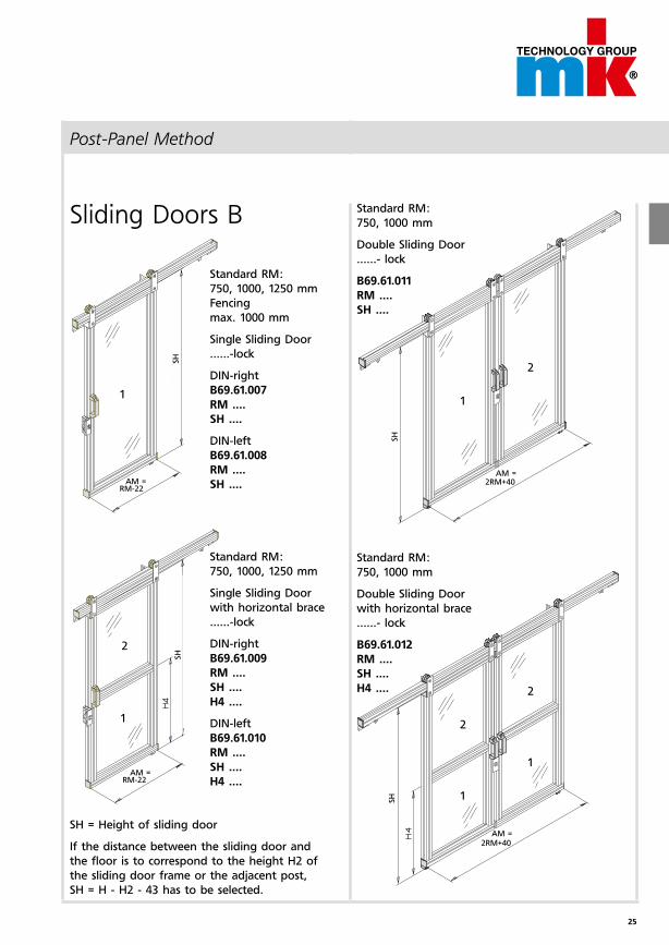
Post-Panel Method
Standard RM:
750, 1000 mm
Double Sliding Door
......- lock
B69.61.011
RM ....
SH ....
Sliding Doors B
Standard RM:
750, 1000 mm
Double Sliding Door
with horizontal brace
......- lock
B69.61.012
RM ....
SH ....
H4 ....
Standard RM:
750, 1000, 1250 mm
Fencing
max. 1000 mm
Single Sliding Door
......-lock
DIN-right
B69.61.007
RM ....
SH ....
DIN-left
B69.61.008
RM ....
SH ....
Standard RM:
750, 1000, 1250 mm
Single Sliding Door
with horizontal brace
......-lock
DIN-right
B69.61.009
RM ....
SH ....
H4 ....
DIN-left
B69.61.010
RM ....
SH ....
H4 ....
SH = Height of sliding door
If the distance between the sliding door and
the floor is to correspond to the height H2 of
the sliding door frame or the adjacent post,
SH = H - H2 - 43 has to be selected.
26
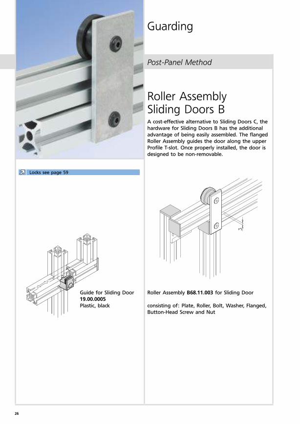
Post-Panel Method
Roller Assembly Sliding Doors BA cost-effective alternative to Sliding Doors C, the
hardware for Sliding Doors B has the additional
advantage of being easily assembled. The flanged
Roller Assembly guides the door along the upper
Profile T-slot. Once properly installed, the door is
designed to be non-removable.
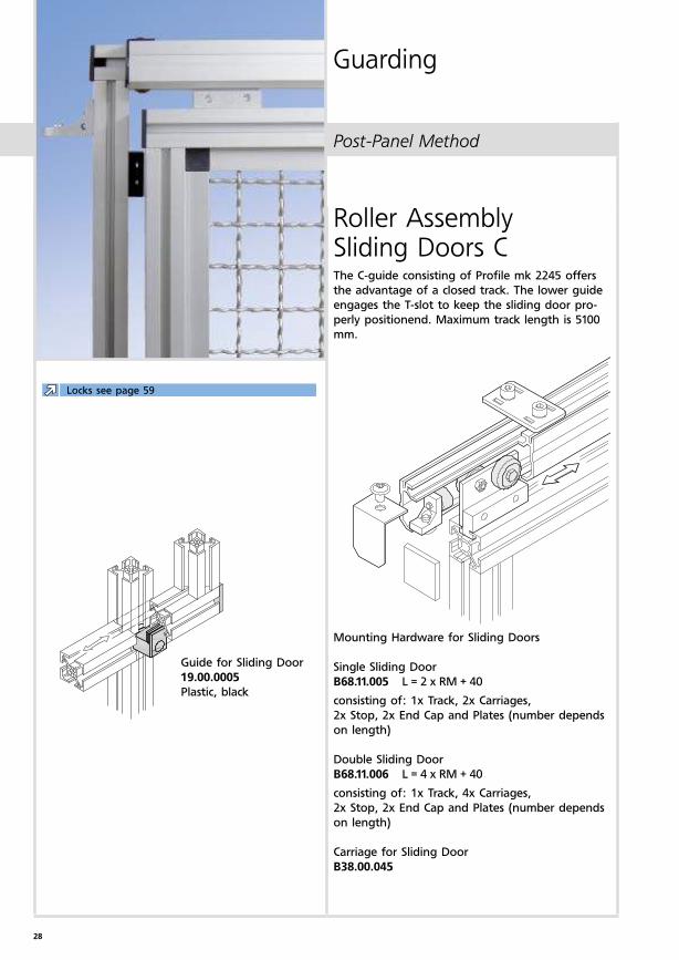
Guide for Sliding Door
19.00.0005
Plastic, black
Roller Assembly B68.11.003 for Sliding Door
consisting of: Plate, Roller, Bolt, Washer, Flanged,
Button-Head Screw and Nut
Guarding
Locks see page 59
27
1
2
2
2
1
1
1
2
1
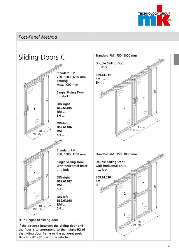
Post-Panel Method
Sliding Doors C
Standard RM:
750, 1000, 1250 mm
Fencing
max. 1000 mm
Single Sliding Door
......-lock
DIN-right
B69.61.015
RM ....
SH ....
DIN-left
B69.61.016
RM ....
SH ....
Standard RM:
750, 1000, 1250 mm
Single Sliding Door
with horizontal brace
......-lock
DIN-right
B69.61.017
RM ....
SH ....
DIN-left
B69.61.018
RM ....
SH ....
Standard RM: 750, 1000 mm
Double Sliding Door
......-lock
B69.61.019
RM ....
SH ....
Standard RM: 750, 1000 mm
Double Sliding Door
with horizontal brace
......-lock
B69.61.020
RM ....
SH ....
SH = Height of sliding door
If the distance between the sliding door and
the floor is to correspond to the height H2 of
the sliding door frame or the adjacent post,
SH = H - H2 - 30 has to be selected.
28
Post-Panel Method
Roller Assembly Sliding Doors CThe C-guide consisting of Profile mk 2245 offers
the advantage of a closed track. The lower guide
engages the T-slot to keep the sliding door pro-
perly positionend. Maximum track length is 5100
mm.
Mounting Hardware for Sliding Doors
Single Sliding Door
B68.11.005 L = 2 x RM + 40
consisting of: 1x Track, 2x Carriages,
2x Stop, 2x End Cap and Plates (number depends
on length)
Double Sliding Door
B68.11.006 L = 4 x RM + 40
consisting of: 1x Track, 4x Carriages,
2x Stop, 2x End Cap and Plates (number depends
on length)
Carriage for Sliding Door
B38.00.045
Guarding
Guide for Sliding Door
19.00.0005
Plastic, black
Locks see page 59
29
2
1
RM
H
RM
LM = RM-40
H3
H6
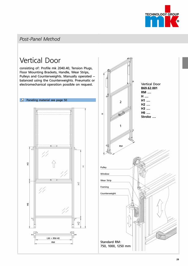
Post-Panel Method
Vertical Door
B69.62.001
RM ....
H ....
H1 ....
H2 ....
H3 ....
H6 ....
Stroke ....
Vertical Doorconsisting of: Profile mk 2040.40, Tension Plugs,
Floor Mounting Brackets, Handle, Wear Strips,
Pulleys and Counterweights. Manually operated –
balanced using the Counterweights. Pneumatic or
electromechanical operation possible on request.
Pulley
Window
Wear Strip
Framing
Counterweight
Standard RM:
750, 1000, 1250 mm
Paneling material see page 50
30
1
2
2
1
RM
LW=2xH
ub
H6
LM = RM-40
RM
H
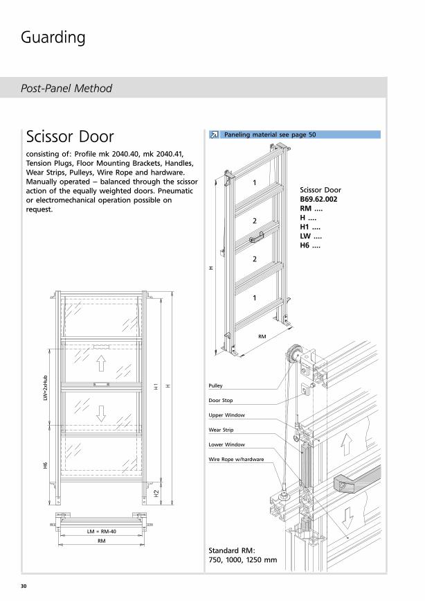
Post-Panel Method
Scissor Doorconsisting of: Profile mk 2040.40, mk 2040.41,
Tension Plugs, Floor Mounting Brackets, Handles,
Wear Strips, Pulleys, Wire Rope and hardware.
Manually operated – balanced through the scissor
action of the equally weighted doors. Pneumatic
or electromechanical operation possible on
request.
Scissor Door
B69.62.002
RM ....
H ....
H1 ....
LW ....
H6 ....
Pulley
Door Stop
Upper Window
Wear Strip
Lower Window
Wire Rope w/hardware
Standard RM:
750, 1000, 1250 mm
Guarding
Paneling material see page 50
31
Notes
32
q w e r t y
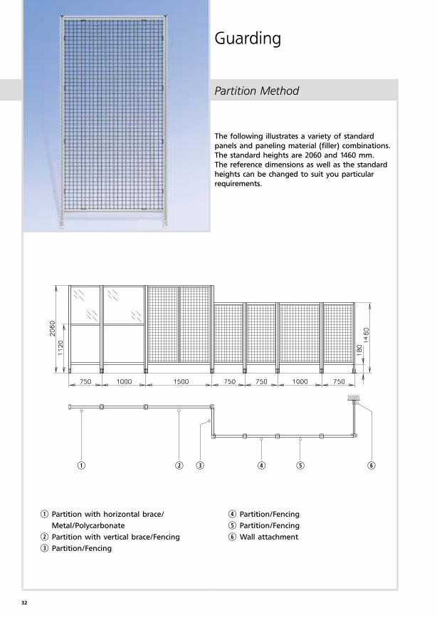
Partition Method
Guarding
The following illustrates a variety of standard
panels and paneling material (filler) combinations.
The standard heights are 2060 and 1460 mm.
The reference dimensions as well as the standard
heights can be changed to suit you particular
requirements.
q Partition with horizontal brace/
Metal/Polycarbonate
w Partition with vertical brace/Fencing
e Partition/Fencing
r Partition/Fencing
t Partition/Fencing
y Wall attachment
33
LM = RM-80
RM
RM
RM
RM
1
2
1
1
2
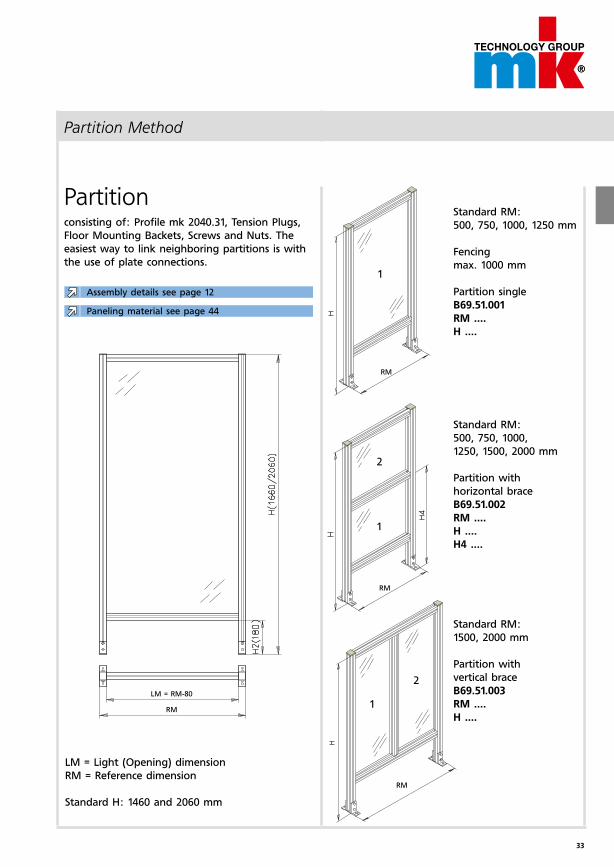
Partition Method
Partitionconsisting of: Profile mk 2040.31, Tension Plugs,
Floor Mounting Backets, Screws and Nuts. The
easiest way to link neighboring partitions is with
the use of plate connections.
LM = Light (Opening) dimension
RM = Reference dimension
Standard H: 1460 and 2060 mm
Standard RM:
500, 750, 1000, 1250 mm
Fencing
max. 1000 mm
Partition single
B69.51.001
RM ....
H ....
Standard RM:
500, 750, 1000,
1250, 1500, 2000 mm
Partition with
horizontal brace
B69.51.002
RM ....
H ....
H4 ....
Standard RM:
1500, 2000 mm
Partition with
vertical brace
B69.51.003
RM ....
H ....
Paneling material see page 44
Assembly details see page 12
34
AM = RM-40
RM
L=RM
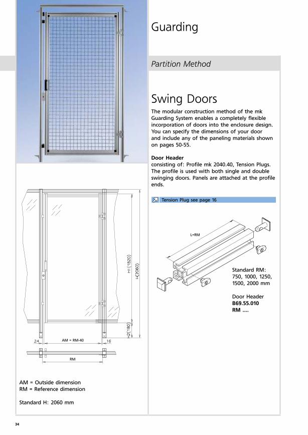
Partition Method
Guarding
Swing DoorsThe modular construction method of the mk
Guarding System enables a completely flexible
incorporation of doors into the enclosure design.
You can specify the dimensions of your door
and include any of the paneling materials shown
on pages 50-55.
Door Header
consisting of: Profile mk 2040.40, Tension Plugs.
The profile is used with both single and double
swinging doors. Panels are attached at the profile
ends.
AM = Outside dimension
RM = Reference dimension
Standard H: 2060 mm
Standard RM:
750, 1000, 1250,
1500, 2000 mm
Door Header
B69.55.010
RM ....
Tension Plug see page 16
35
1
1
2
2
AM =
RM-72
1
AM = RM-72
2
1
2
AM = RM-40
AM = RM-40
1
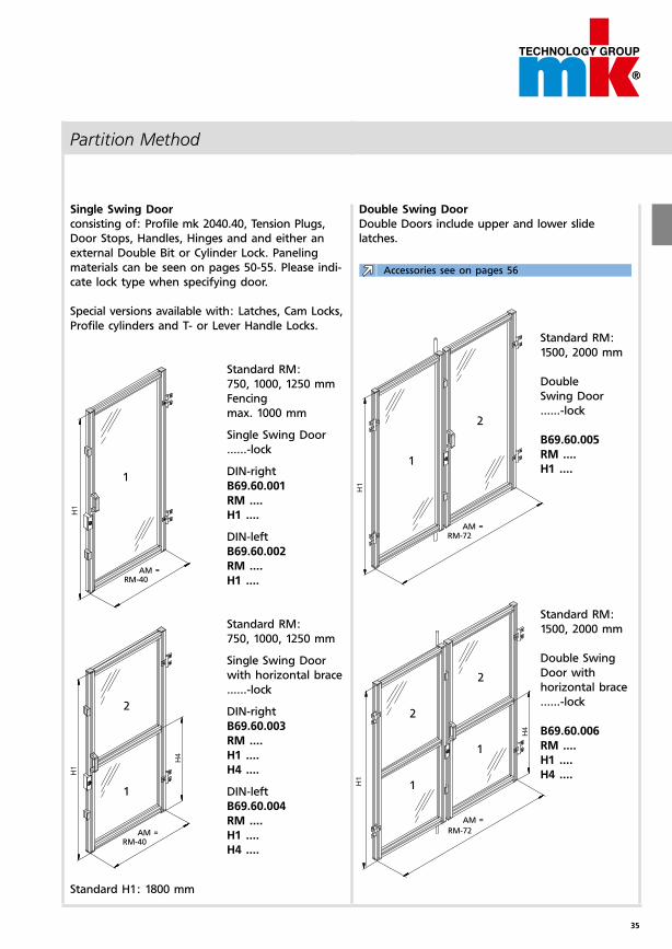
Partition Method
Double Swing Door
Double Doors include upper and lower slide
latches.
Single Swing Door
consisting of: Profile mk 2040.40, Tension Plugs,
Door Stops, Handles, Hinges and and either an
external Double Bit or Cylinder Lock. Paneling
materials can be seen on pages 50-55. Please indi-
cate lock type when specifying door.
Special versions available with: Latches, Cam Locks,
Profile cylinders and T- or Lever Handle Locks.Standard RM:
1500, 2000 mm
Double
Swing Door
......-lock
B69.60.005
RM ....
H1 ....
Standard RM:
1500, 2000 mm
Double Swing
Door with
horizontal brace
......-lock
B69.60.006
RM ....
H1 ....
H4 ....
Standard RM:
750, 1000, 1250 mm
Fencing
max. 1000 mm
Single Swing Door
......-lock
DIN-right
B69.60.001
RM ....
H1 ....
DIN-left
B69.60.002
RM ....
H1 ....
Standard RM:
750, 1000, 1250 mm
Single Swing Door
with horizontal brace
......-lock
DIN-right
B69.60.003
RM ....
H1 ....
H4 ....
DIN-left
B69.60.004
RM ....
H1 ....
H4 ....
Standard H1: 1800 mm
Accessories see on pages 56
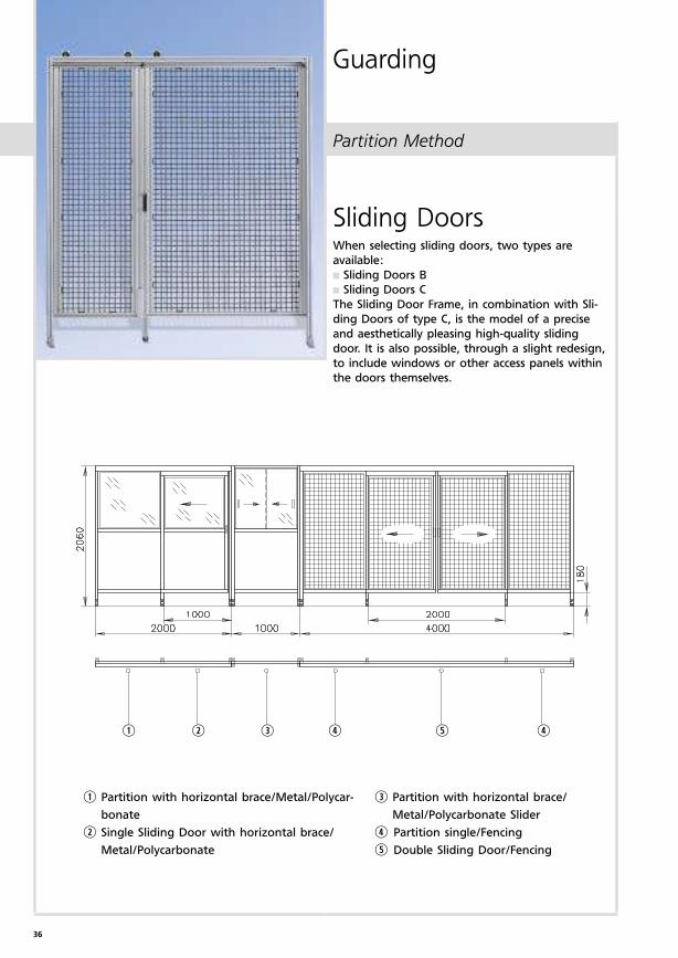
36
q w e r t r
Partition Method
Guarding
Sliding DoorsWhen selecting sliding doors, two types are
available:
Sliding Doors B
Sliding Doors C
The Sliding Door Frame, in combination with Sli-
ding Doors of type C, is the model of a precise
and aesthetically pleasing high-quality sliding
door. It is also possible, through a slight redesign,
to include windows or other access panels within
the doors themselves.
q Partition with horizontal brace/Metal/Polycar-
bonate
w Single Sliding Door with horizontal brace/
Metal/Polycarbonate
e Partition with horizontal brace/
Metal/Polycarbonate Slider
r Partition single/Fencing
t Double Sliding Door/Fencing
37
RM
RM
L=RM
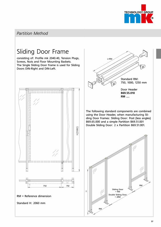
Partition Method
Sliding Door Frameconsisting of: Profile mk 2040.40, Tension Plugs,
Screws, Nuts and Floor Mounting Backets.
The Single Sliding Door Frame is used for Sliding
Doors DIN-Right and DIN-Left.
The following standard components are combi ned
using the Door Header, when manufacturing Sli-
ding Door Frames: Sliding Door: Post (less angles)
B69.65.000 and a simple Partition B69.51.001
Double Sliding Door: 2 x Partition B69.51.001.
RM = Reference dimension
Standard H: 2060 mm
Sliding Door = RM
Double Sliding Door = 2RM
Standard RM:
750, 1000, 1250 mm
Door Header
B69.55.010
RM ....
38
AM = RM+18
1 1
2
2
2
1
1
2
1
AM = RM+18
AM = 2RM+80
AM = 2RM+80
SH
SH
SH
SH
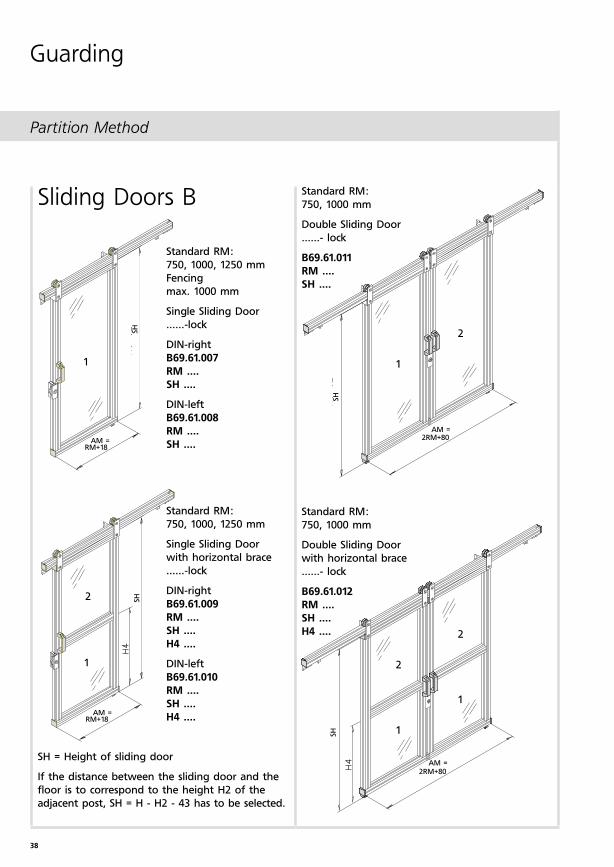
Partition Method
Guarding
Standard RM:
750, 1000 mm
Double Sliding Door
......- lock
B69.61.011
RM ....
SH ....
Sliding Doors B
Standard RM:
750, 1000 mm
Double Sliding Door
with horizontal brace
......- lock
B69.61.012
RM ....
SH ....
H4 ....
Standard RM:
750, 1000, 1250 mm
Fencing
max. 1000 mm
Single Sliding Door
......-lock
DIN-right
B69.61.007
RM ....
SH ....
DIN-left
B69.61.008
RM ....
SH ....
Standard RM:
750, 1000, 1250 mm
Single Sliding Door
with horizontal brace
......-lock
DIN-right
B69.61.009
RM ....
SH ....
H4 ....
DIN-left
B69.61.010
RM ....
SH ....
H4 ....
SH = Height of sliding door
If the distance between the sliding door and the
floor is to correspond to the height H2 of the
adjacent post, SH = H - H2 - 43 has to be selected.
39
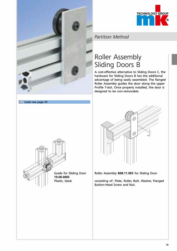
Partition Method
Roller Assembly Sliding Doors BA cost-effective alternative to Sliding Doors C, the
hardware for Sliding Doors B has the additional
advantage of being easily assembled. The flanged
Roller Assembly guides the door along the upper
Profile T-slot. Once properly installed, the door is
designed to be non-removable.
Roller Assembly B68.11.003 for Sliding Door
consisting of: Plate, Roller, Bolt, Washer, Flanged
Button-Head Screw and Nut.
Guide for Sliding Door
19.00.0005
Plastic, black
Locks see page 59
40
1
2
2
2
1
1
1
2
1
Partition Method
Guarding
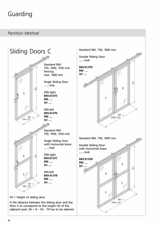
Sliding Doors C
Standard RM:
750, 1000, 1250 mm
Fencing
max. 1000 mm
Single Sliding Door
......-lock
DIN-right
B69.61.015
RM ....
SH ....
DIN-left
B69.61.016
RM ....
SH ....
Standard RM:
750, 1000, 1250 mm
Single Sliding Door
with horizontal brace
......-lock
DIN-right
B69.61.017
RM ....
SH ....
DIN-left
B69.61.018
RM ....
SH ....
Standard RM: 750, 1000 mm
Double Sliding Door
......-lock
B69.61.019
RM ....
SH ....
SH = Height of sliding door
If the distance between the sliding door and the
floor is to correspond to the height H2 of the
adjacent post, SH = H - H2 - 70 has to be selected.
Standard RM: 750, 1000 mm
Double Sliding Door
with horizontal brace
......-lock
B69.61.020
RM ....
SH ....
41
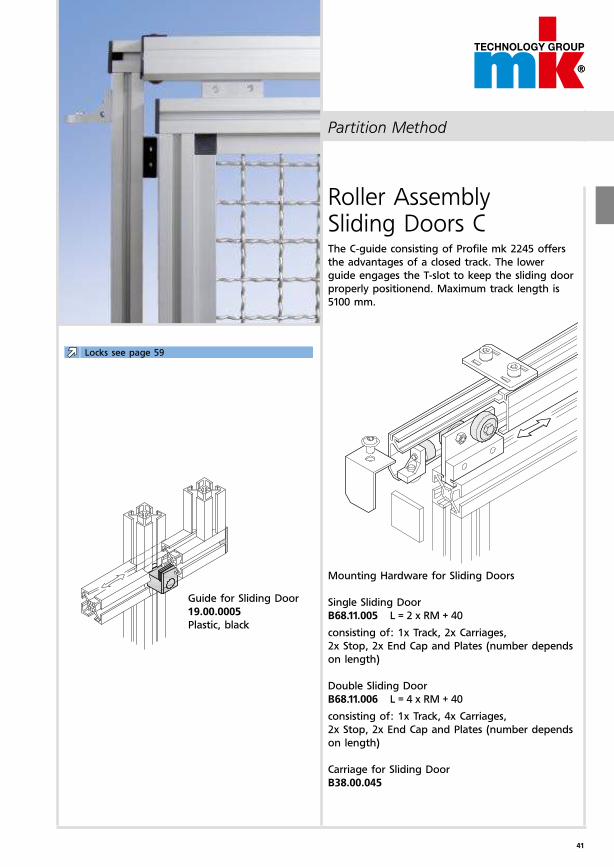
Partition Method
Roller Assembly Sliding Doors CThe C-guide consisting of Profile mk 2245 offers
the advantages of a closed track. The lower
guide engages the T-slot to keep the sliding door
properly positionend. Maximum track length is
5100 mm.
Mounting Hardware for Sliding Doors
Single Sliding Door
B68.11.005 L = 2 x RM + 40
consisting of: 1x Track, 2x Carriages,
2x Stop, 2x End Cap and Plates (number depends
on length)
Double Sliding Door
B68.11.006 L = 4 x RM + 40
consisting of: 1x Track, 4x Carriages,
2x Stop, 2x End Cap and Plates (number depends
on length)
Carriage for Sliding Door
B38.00.045
Guide for Sliding Door
19.00.0005
Plastic, black
Locks see page 59
42
H3 H
H2
RM
LM = RM-80
H6
2
1
RM
H
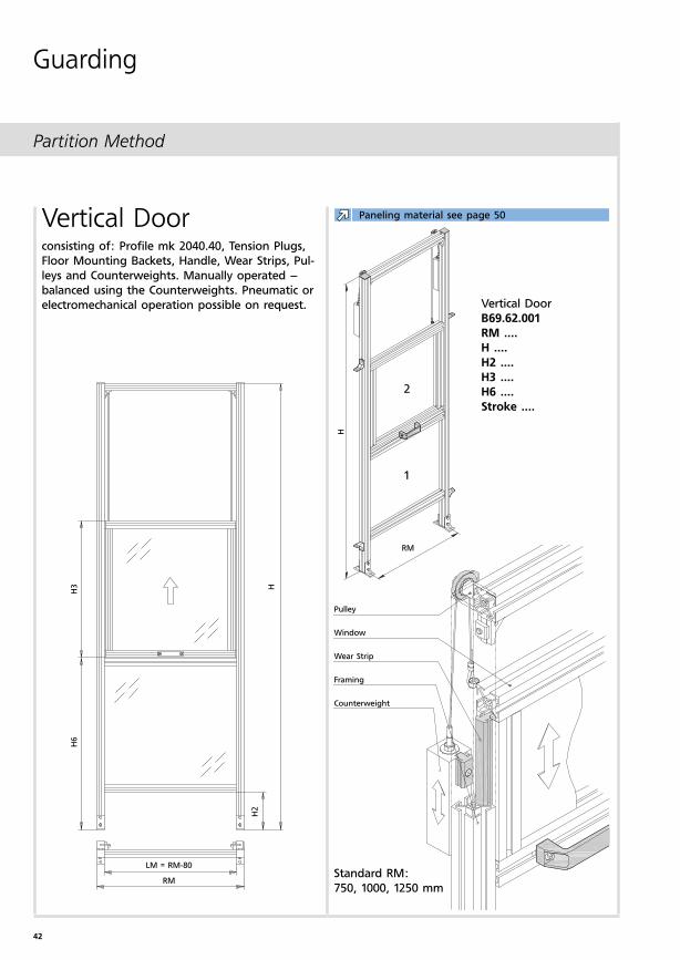
Vertical Door
B69.62.001
RM ....
H ....
H2 ....
H3 ....
H6 ....
Stroke ....
Vertical Doorconsisting of: Profile mk 2040.40, Tension Plugs,
Floor Mounting Backets, Handle, Wear Strips, Pul-
leys and Counterweights. Manually operated –
balanced using the Counterweights. Pneumatic or
electromechanical operation possible on request.
Pulley
Window
Wear Strip
Framing
Counterweight
Standard RM:
750, 1000, 1250 mm
Partition Method
Guarding
Paneling material see page 50
43
LW=2xH
ub
H6
H2
H
LM = RM-80
RM
1
2
2
1
RM
H
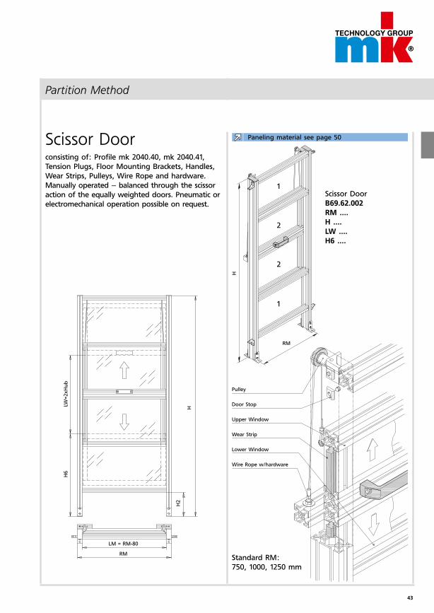
Scissor Doorconsisting of: Profile mk 2040.40, mk 2040.41,
Tension Plugs, Floor Mounting Brackets, Handles,
Wear Strips, Pulleys, Wire Rope and hardware.
Manually operated – balanced through the scissor
action of the equally weighted doors. Pneumatic or
electromechanical operation possible on request.
Scissor Door
B69.62.002
RM ....
H ....
LW ....
H6 ....
Pulley
Door Stop
Upper Window
Wear Strip
Lower Window
Wire Rope w/hardware
Standard RM:
750, 1000, 1250 mm
Partition Method
Paneling material see page 50
44
LM
LH
H4
LH
-10
LM-10
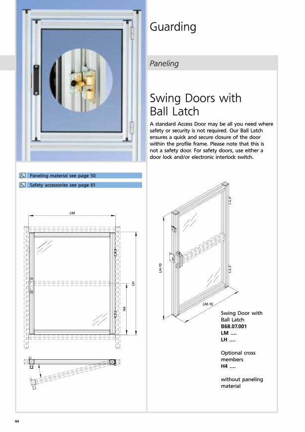
Paneling
Guarding
Swing Doors with Ball LatchA standard Access Door may be all you need where
safety or security is not required. Our Ball Latch
ensures a quick and secure closure of the door
within the profile frame. Please note that this is
not a safety door. For safety doors, use either a
door lock and/or electronic interlock switch.
Swing Door with
Ball Latch
B68.07.001
LM ....
LH ....
Optional cross
members
H4 ....
without paneling
material
Paneling material see page 50
Safety accessories see page 61
45
LM
LH
H4
H3
LH
-10
LM-10
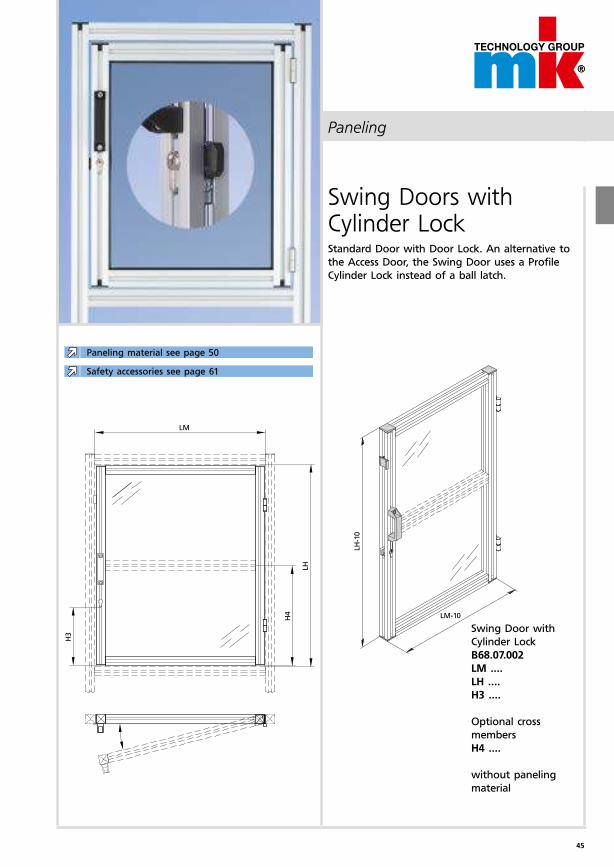
Paneling
Swing Doors with Cylinder LockStandard Door with Door Lock. An alternative to
the Access Door, the Swing Door uses a Profile
Cylinder Lock instead of a ball latch.
Swing Door with
Cylinder Lock
B68.07.002
LM ....
LH ....
H3 ....
Optional cross
members
H4 ....
without paneling
material
Paneling material see page 50
Safety accessories see page 61
46
LM
LM-10
LH
H3
LH
-10
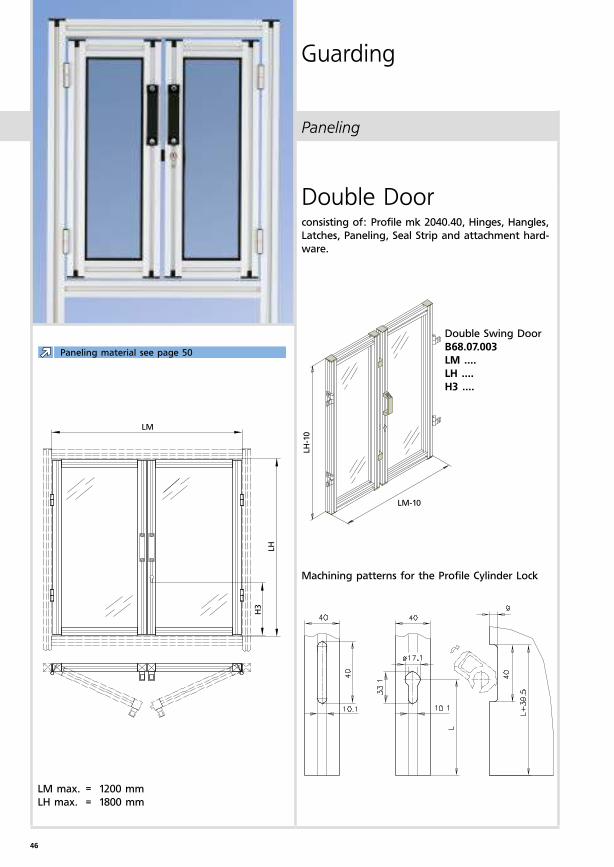
Paneling
Guarding
Double Doorconsisting of: Profile mk 2040.40, Hinges, Hangles,
Latches, Paneling, Seal Strip and attachment hard-
ware.
Machining patterns for the Profile Cylinder Lock
Double Swing Door
B68.07.003
LM ....
LH ....
H3 ....
LM max. = 1200 mm
LH max. = 1800 mm
Paneling material see page 50
47
LM
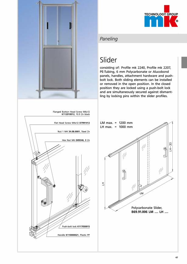
Paneling
Sliderconsisting of: Profile mk 2240, Profile mk 2207,
PE-Tubing, 6 mm Polycarbonate or Alucobond
panels, handles, attachment hardware and push-
bolt lock. Both sliding elements can be installed
or removed in the open position. In the closed
position they are locked using a push-bolt lock
and are simultaneously secured against dismant-
ling by locking pins within the slider profiles.
Flanged Button Head Screw M6x12 K112010012, 10.9 Zn black
Flat Head Screw M4x12 D7991412
Nut 1 M4 34.08.0001, Steel Zn
Hex Nut M6 D09346, 8 Zn
Push-bolt lock K117050015
Handle K110000021, Plastic PP
LM max. = 1200 mm
LH max. = 1000 mm
Polycarbonate Slider,
B69.91.006 LM .... LH ....
48
LM
LM-20
LH
LH
-10
Paneling
Guarding
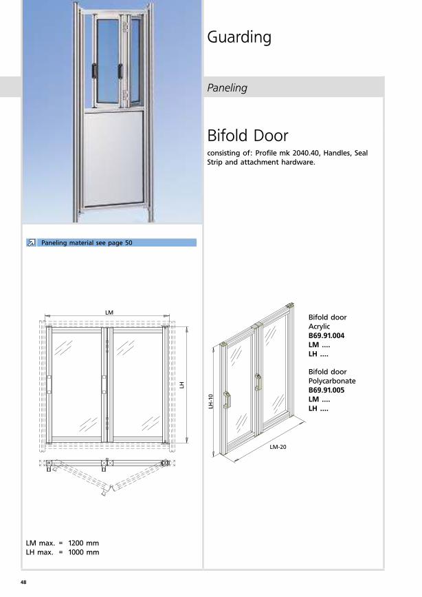
Bifold Doorconsisting of: Profile mk 2040.40, Handles, Seal
Strip and attachment hardware.
Bifold door
Acrylic
B69.91.004
LM ....
LH ....
Bifold door
Polycarbonate
B69.91.005
LM ....
LH ....
LM max. = 1200 mm
LH max. = 1000 mm
Paneling material see page 50
49
50
1) nicht in USA. 2) nur in USA.
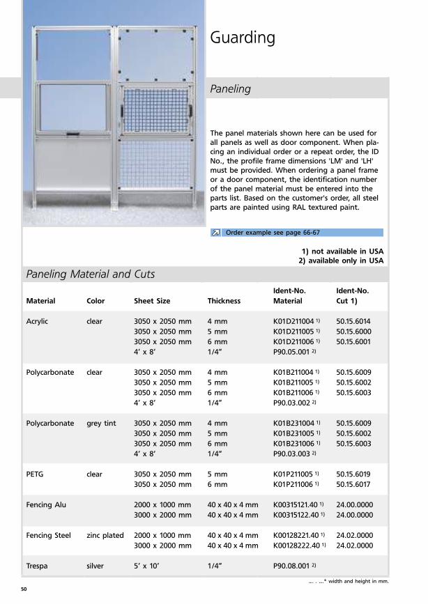
Paneling Material and Cuts
Ident-No. Ident-No.
Material Color Sheet Size Thickness Material Cut 1)
Acrylic clear 3050 x 2050 mm 4 mm K01D211004 1) 50.15.6014
3050 x 2050 mm 5 mm K01D211005 1) 50.15.6000
3050 x 2050 mm 6 mm K01D211006 1) 50.15.6001
4‘ x 8‘ 1/4“ P90.05.001 2)
Polycarbonate clear 3050 x 2050 mm 4 mm K01B211004 1) 50.15.6009
3050 x 2050 mm 5 mm K01B211005 1) 50.15.6002
3050 x 2050 mm 6 mm K01B211006 1) 50.15.6003
4‘ x 8‘ 1/4“ P90.03.002 2)
Polycarbonate grey tint 3050 x 2050 mm 4 mm K01B231004 1) 50.15.6009
3050 x 2050 mm 5 mm K01B231005 1) 50.15.6002
3050 x 2050 mm 6 mm K01B231006 1) 50.15.6003
4‘ x 8‘ 1/4“ P90.03.003 2)
PETG clear 3050 x 2050 mm 5 mm K01P211005 1) 50.15.6019
3050 x 2050 mm 6 mm K01P211006 1) 50.15.6017
Fencing Alu 2000 x 1000 mm 40 x 40 x 4 mm K00315121.40 1) 24.00.0000
3000 x 2000 mm 40 x 40 x 4 mm K00315122.40 1) 24.00.0000
Fencing Steel zinc plated 2000 x 1000 mm 40 x 40 x 4 mm K00128221.40 1) 24.02.0000
3000 x 2000 mm 40 x 40 x 4 mm K00128222.40 1) 24.02.0000
Trespa silver 5‘ x 10‘ 1/4“ P90.08.001 2)
Paneling
Guarding
The panel materials shown here can be used for
all panels as well as door component. When pla-
cing an individual order or a repeat order, the ID
No., the profile frame dimensions 'LM' and 'LH'
must be provided. When ordering a panel frame
or a door component, the identification number
of the panel material must be entered into the
parts list. Based on the customer's order, all steel
parts are painted using RAL textured paint.
…. . ….* width and height in mm.
1) not available in USA
2) available only in USA
Order example see page 66-67
51
Paneling Material and Cuts
Ident-No. Ident-No.
Material Color max. Sheet Size Thickness Material Cut 1)
Fencing black 2000 x 1000 mm 40 x 40 x 4 mm K00128321.40 1) 24.05.0000
Steel powder-coated 2000 x 1250 mm 40 x 40 x 4 mm K00128323.40 1) 24.05.0000
2000 x 1500 mm 40 x 40 x 4 mm K00128324.40 1) 24.05.0000
4‘ x 8‘ 1“x1“, 12 Ga. P90.00.007 2)
4‘ x 8‘ 1/2“x1/2“, 16 Ga. P90.00.009 2)
yellow 4‘ x 8‘ 1“x1“, 12 Ga. P90.00.008 2)
4‘ x 8‘ 1/2“x1/2“, 16 Ga. P90.00.010 2)
Alucobond silver anod. 3000 x 1500 mm 4 mm K00316223004 1) 50.15.4001
4/2,5 mm reworked 50.15.3005
3000 x 1500 mm 6 mm K00316223006 1) 50.15.4002
Dibond white 4‘ x 8‘ 2 mm P90.06.001 2)
Steel zinc plated 2000 x 1000 mm 1,5 mm K00112121150 1) 07.28. …. . ….*
painted 2000 x 1000 mm 1,5 mm K00112131150 1) 07.28. …. . ….*
zinc plated 4‘ x 8‘ 18 Ga. P57.02.000 2)
Stainless polished 2000 x 1000 mm 1,5 mm K00205121150 1) 07.29. …. . ….*
Steel 4‘ x 8‘ 20 Ga. P57.01.000 2)
Aluminum silver anod. 2000 x 1000 mm 1,5 mm K00305321150 1) 07.30. …. . ….*
2000 x 1000 mm 2 mm K00305321200 1) 07.33. …. . ….*
Expanded black 4‘ x 8‘ 1/4“ P90.07.001 2)
PVC blue 4‘ x 8‘ 1/4“ P90.07.002 2)
grey 4‘ x 8‘ 1/4“ P90.07.003 2)
white 4‘ x 8‘ 1/4“ P90.07.004 2)
Alumalite silver 4‘ x 8‘ 1/4“ P90.04.001 2)
Sizing
Installed using Width Height Installed using Width Height
Seal Strip LM+20 mm LH+20 mm Angle LM LH
Panel Clamp LM-31 mm LH-31 mm Fencing w. Clamp Profile LM+10 mm LH+10 mm
Panel Block LM LH Fencing LM+20 mm LH+20 mm
Paneling
…. . ….* width and height in mm.
1) not available in USA
2) available only in USA
52
1.5-3
4-6
10
Paneling
Guarding
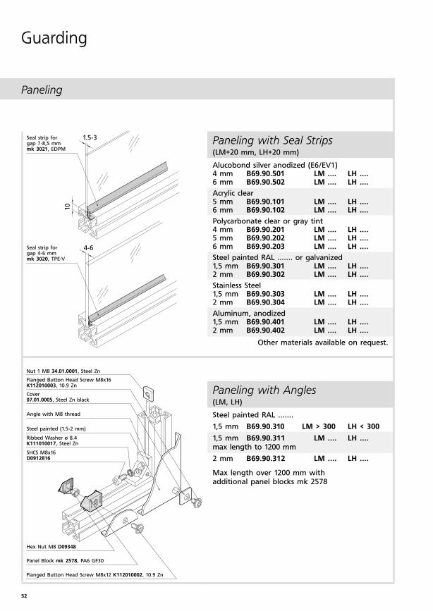
Paneling with Seal Strips (LM+20 mm, LH+20 mm)
Alucobond silver anodized (E6/EV1)4 mm B69.90.501 LM .... LH ....6 mm B69.90.502 LM .... LH ....
Acrylic clear 5 mm B69.90.101 LM .... LH ....6 mm B69.90.102 LM .... LH ....
Polycarbonate clear or gray tint4 mm B69.90.201 LM .... LH ....5 mm B69.90.202 LM .... LH ....6 mm B69.90.203 LM .... LH ....
Steel painted RAL ....... or galvanized1,5 mm B69.90.301 LM .... LH ....2 mm B69.90.302 LM .... LH ....
Stainless Steel1,5 mm B69.90.303 LM .... LH ....2 mm B69.90.304 LM .... LH ....
Aluminum, anodized1,5 mm B69.90.401 LM .... LH ....2 mm B69.90.402 LM .... LH ....
Paneling with Angles (LM, LH)
Steel painted RAL .......
1,5 mm B69.90.310 LM > 300 LH < 300
1,5 mm B69.90.311 LM .... LH .... max length to 1200 mm
2 mm B69.90.312 LM .... LH ....
Max length over 1200 mm with additional panel blocks mk 2578
Other materials available on request.
Nut 1 M8 34.01.0001, Steel Zn
Flanged Button Head Screw M8x16 K112010003, 10.9 Zn
Cover 07.01.0005, Steel Zn black
Angle with M8 thread
Steel painted (1.5-2 mm)
Ribbed Washer ø 8.4 K111010017, Steel Zn
SHCS M8x16 D0912816
Hex Nut M8 D09348
Panel Block mk 2578, PA6 GF30
Flanged Button Head Screw M8x12 K112010002, 10.9 Zn
Seal strip for gap 7-8,5 mmmk 3021, EDPM
Seal strip for gap 4-6 mm mk 3020, TPE-V
53
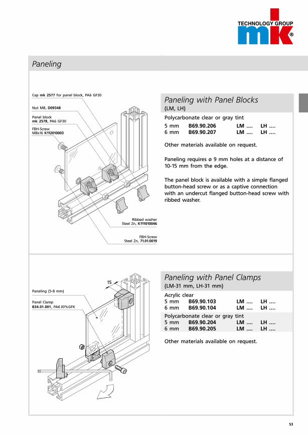
15Paneling with Panel Clamps(LM-31 mm, LH-31 mm)
Acrylic clear5 mm B69.90.103 LM .... LH ....6 mm B69.90.104 LM .... LH ....
Polycarbonate clear or gray tint5 mm B69.90.204 LM .... LH ....6 mm B69.90.205 LM .... LH ....
Other materials available on request.
Paneling
Paneling with Panel Blocks (LM, LH)
Polycarbonate clear or gray tint
5 mm B69.90.206 LM .... LH ....6 mm B69.90.207 LM .... LH ....
Other materials available on request.
Paneling (5-8 mm)
Panel Clamp
B34.01.001, PA6 30%GFK
Paneling requires ø 9 mm holes at a distance of
10-15 mm from the edge.
Cap mk 2577 for panel block, PA6 GF30
Nut M8, D09348
Panel block mk 2578, PA6 GF30
FBH-Screw M8x16 K112010003
Ribbed washer Steel Zn, K111010046
FBH-Screw Steel Zn, 71.01.0019
The panel block is available with a simple flanged
button-head screw or as a captive connection
with an undercut flanged button-head screw with
ribbed washer.
54
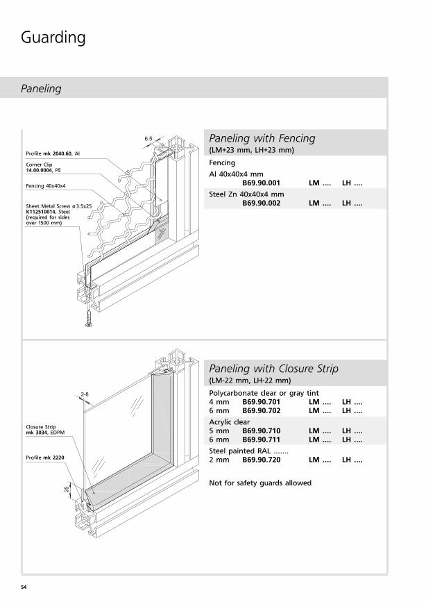
Paneling with Fencing(LM+23 mm, LH+23 mm)
Fencing
Al 40x40x4 mm B69.90.001 LM .... LH ....
Steel Zn 40x40x4 mm B69.90.002 LM .... LH ....
Paneling with Closure Strip (LM-22 mm, LH-22 mm)
Polycarbonate clear or gray tint4 mm B69.90.701 LM .... LH ....6 mm B69.90.702 LM .... LH ....
Acrylic clear 5 mm B69.90.710 LM .... LH ....6 mm B69.90.711 LM .... LH ....
Steel painted RAL .......2 mm B69.90.720 LM .... LH ....
Not for safety guards allowed
Paneling
Guarding
Profile mk 2040.60, Al
Corner Clip14.00.0004, PE
Fencing 40x40x4
Sheet Metal Screw ø 3.5x25K112510014, Steel (required for sidesover 1500 mm)
Closure Stripmk 3034, EDPM
Profile mk 2220
55
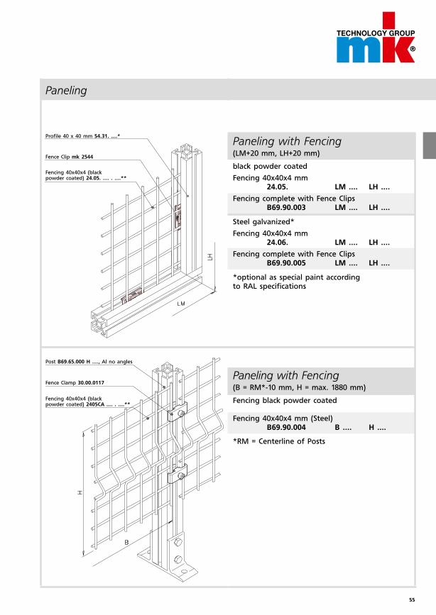
Paneling with Fencing (LM+20 mm, LH+20 mm)
black powder coated
Fencing 40x40x4 mm 24.05. LM .... LH ....
Fencing complete with Fence Clips B69.90.003 LM .... LH ....
Steel galvanized*
Fencing 40x40x4 mm 24.06. LM .... LH ....
Fencing complete with Fence Clips B69.90.005 LM .... LH ....
*optional as special paint according to RAL specifications
Paneling with Fencing (B = RM*-10 mm, H = max. 1880 mm)
Fencing black powder coated
Fencing 40x40x4 mm (Steel) B69.90.004 B .... H ....
*RM = Centerline of Posts
Profile 40 x 40 mm 54.31. ....*
Fence Clip mk 2544
Fencing 40x40x4 (black powder coated) 24.05. .... . ....**
Post B69.65.000 H ...., Al no angles
Fence Clamp 30.00.0117
Fencing 40x40x4 (black powder coated) 2405CA .... . ....**
Paneling
56
155
65
65
39
40
4
70
39
ø 9
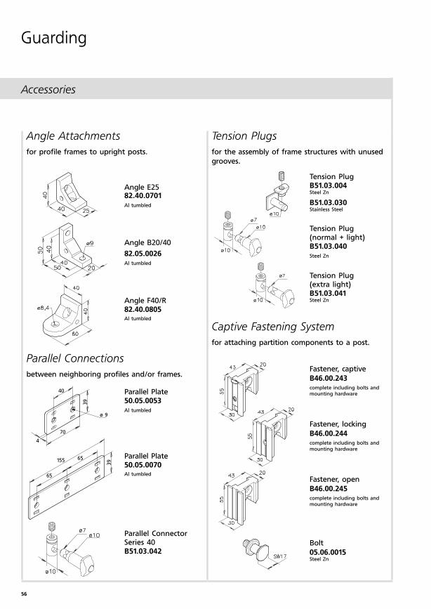
Accessories
Guarding
Captive Fastening System
for attaching partition components to a post.
Angle Attachments
for profile frames to upright posts.
Tension Plugs
for the assembly of frame structures with unused
grooves.
Parallel Connections
between neighboring profiles and/or frames.
Angle E2582.40.0701Al tumbled
Angle B20/40
82.05.0026Al tumbled
Angle F40/R82.40.0805Al tumbled
Parallel Plate50.05.0053Al tumbled
Parallel Plate50.05.0070Al tumbled
Fastener, captive
B46.00.243complete including bolts and mounting hardware
Fastener, locking
B46.00.244complete including bolts and mounting hardware
Fastener, open
B46.00.245complete including bolts and mounting hardware
Bolt
05.06.0015Steel Zn
Parallel ConnectorSeries 40B51.03.042
Tension PlugB51.03.004Steel Zn
B51.03.030Stainless Steel
Tension Plug (normal + light)B51.03.040Steel Zn
Tension Plug(extra light)B51.03.041Steel Zn
57
35
11
6,5
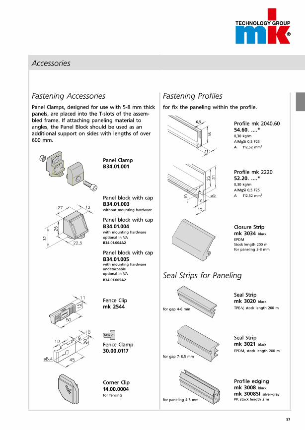
Accessories
Fastening Profiles
for fix the paneling within the profile.
Profile mk 2040.6054.60. ....*0,30 kg/m
AlMgSi 0,5 F25
A 112,52 mm2
Profile mk 222052.20. ....*0,30 kg/m
AlMgSi 0,5 F25
A 112,52 mm2
Closure Stripmk 3034 black
EPDM
Stock length 200 m
for paneling 2-8 mm
Fastening Accessories
Panel Clamps, designed for use with 5-8 mm thick
panels, are placed into the T-slots of the assem-
bled frame. If attaching paneling material to
angles, the Panel Block should be used as an
additional support on sides with lengths of over
600 mm.
Panel ClampB34.01.001
Panel block with capB34.01.003without mounting hardware
Panel block with cap
B34.01.004with mounting hardware
optional in VA
B34.01.004A2
Panel block with cap
B34.01.005with mounting hardware
undetachable
optional in VA
B34.01.005A2
Fence Clipmk 2544
Fence Clamp30.00.0117
Corner Clip
14.00.0004for fencing
Seal Stripmk 3020 black
TPE-V, stock length 200 m
Seal Stripmk 3021 black
EPDM, stock length 200 m
Profile edgingmk 3008 black
mk 3008SI silver-gray
PP, stock length 2 m
Seal Strips for Paneling
for paneling 4-6 mm
for gap 4-6 mm
for gap 7-8,5 mm
58
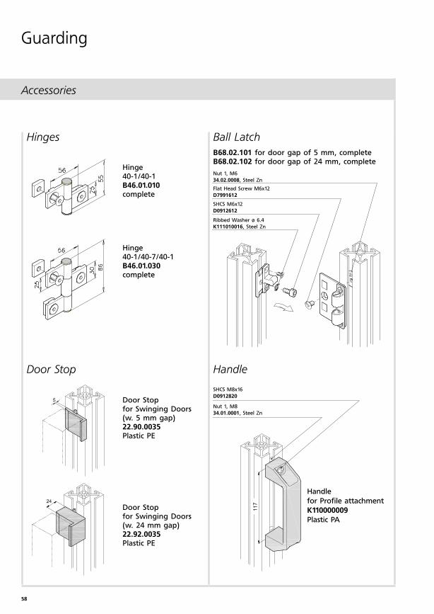
Accessories
Guarding
Hinges Ball Latch
B68.02.101 for door gap of 5 mm, completeB68.02.102 for door gap of 24 mm, complete
Door Stop Handle
Handle
for Profile attachment
K110000009
Plastic PA
SHCS M8x16
D0912820
Nut 1, M8
34.01.0001, Steel Zn
Hinge 40-1/40-1B46.01.010complete
Hinge 40-1/40-7/40-1B46.01.030complete
Door Stopfor Swinging Doors(w. 5 mm gap)22.90.0035Plastic PE
Door Stopfor Swinging Doors(w. 24 mm gap)22.92.0035Plastic PE
Nut 1, M6
34.02.0008, Steel Zn
Flat Head Screw M6x12
D7991612
SHCS M6x12
D0912612
Ribbed Washer ø 6.4
K111010016, Steel Zn
59
42
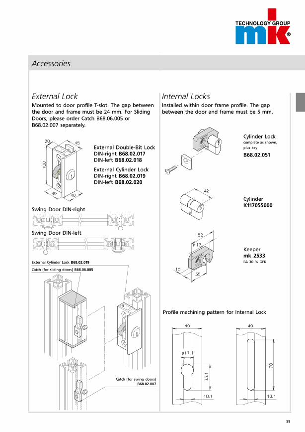
Accessories
External Double-Bit LockDIN-right B68.02.017DIN-left B68.02.018
External Cylinder LockDIN-right B68.02.019DIN-left B68.02.020
Cylinder Lockcomplete as shown,
plus key
B68.02.051
CylinderK117055000
Keepermk 2533PA 30 % GFK
External LockMounted to door profile T-slot. The gap between
the door and frame must be 24 mm. For Sliding
Doors, please order Catch B68.06.005 or
B68.02.007 separately.
Internal LocksInstalled within door frame profile. The gap
between the door and frame must be 5 mm.
Profile machining pattern for Internal Lock
Swing Door DIN-right
Swing Door DIN-left
External Cylinder Lock B68.02.019
Catch (for sliding doors) B68.06.005
Catch (for swing doors)
B68.02.007
60
Accessories
Guarding
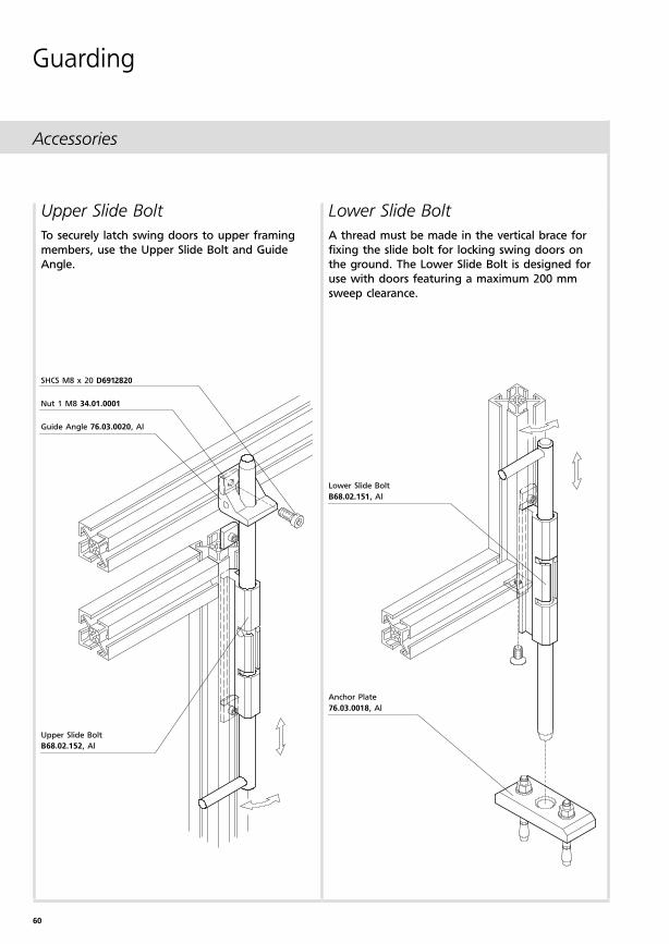
Lower Slide Bolt
A thread must be made in the vertical brace for
fixing the slide bolt for locking swing doors on
the ground. The Lower Slide Bolt is designed for
use with doors featuring a maximum 200 mm
sweep clearance.
Upper Slide Bolt
To securely latch swing doors to upper framing
members, use the Upper Slide Bolt and Guide
Angle.
Lower Slide Bolt
B68.02.151, Al
Anchor Plate
76.03.0018, Al
SHCS M8 x 20 D6912820
Nut 1 M8 34.01.0001
Guide Angle 76.03.0020, Al
Upper Slide Bolt
B68.02.152, Al
61
Safety Accessories
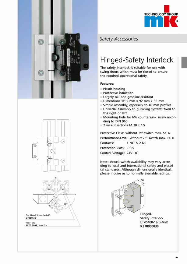
Hinged-Safety InterlockThe safety interlock is suitable for use with
swing doors which must be closed to ensure
the required operational safety.
Features:
Plastic housing
Protective insulation
Largely oil- and gasoline-resistant
Dimensions 111.5 mm x 92 mm x 36 mm
Simple assembly, especially to 40 mm profiles
Universal assembly to guarding systems fixed to
the right or left
Mounting hole for M6 countersunk screw accor-
ding to DIN 965
2 wire insertions M 20 x 1.5
Protective Class: without 2nd switch max. SK 4
Performance-Level: without 2nd switch max. PL e
Contacts: 1 NO & 2 NC
Protection Class: IP 65
Control Voltage: 24V DC
Note: Actual switch availability may vary accor-ding to local and international safety and electri-cal standards. Although dimensionally identical, please inquire as to normally available ratings.
Flat Head Screw M6x16D7991616
Nut 1M6 34.02.0008, Steel Zn
Hinged-
Safety Interlock
ETVS400-12/B-M20
K370000030
62
Safety Accessories
Guarding
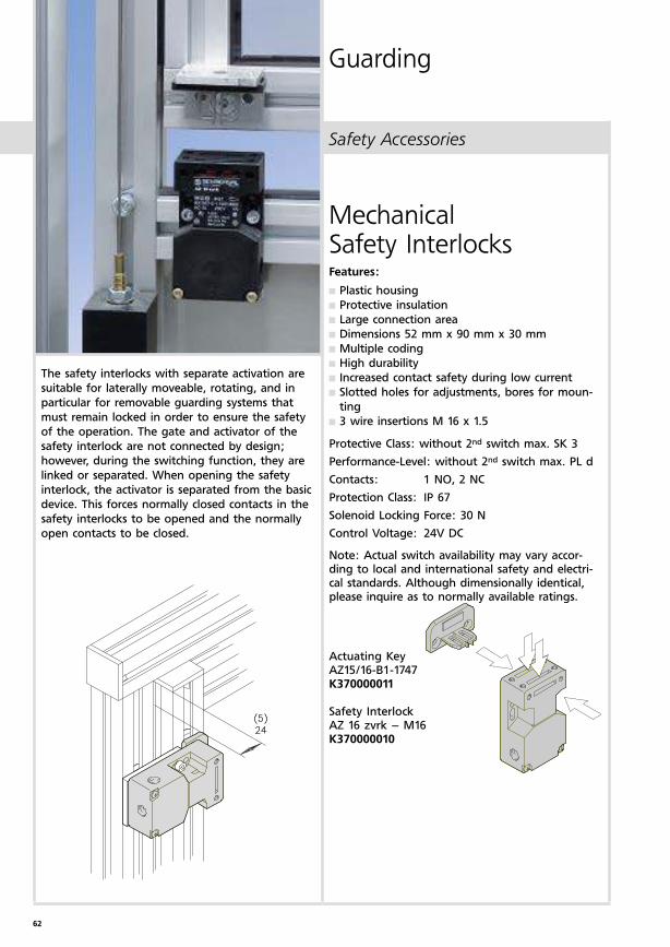
Actuating Key AZ15/16-B1-1747K370000011
Safety InterlockAZ 16 zvrk – M16K370000010
Mechanical Safety InterlocksFeatures:
Plastic housing
Protective insulation
Large connection area
Dimensions 52 mm x 90 mm x 30 mm
Multiple coding
High durability
Increased contact safety during low current
Slotted holes for adjustments, bores for moun-
ting
3 wire insertions M 16 x 1.5
Protective Class: without 2nd switch max. SK 3
Performance-Level: without 2nd switch max. PL d
Contacts: 1 NO, 2 NC
Protection Class: IP 67
Solenoid Locking Force: 30 N
Control Voltage: 24V DC
Note: Actual switch availability may vary accor-ding to local and international safety and electri-cal standards. Although dimensionally identical, please inquire as to normally available ratings.
The safety interlocks with separate activation are
suitable for laterally moveable, rotating, and in
particular for removable guarding systems that
must remain locked in order to ensure the safety
of the operation. The gate and activator of the
safety interlock are not connected by design;
however, during the switching function, they are
linked or separated. When opening the safety
interlock, the activator is separated from the basic
device. This forces normally closed contacts in the
safety interlocks to be opened and the normally
open contacts to be closed.
63
Safety Accessories
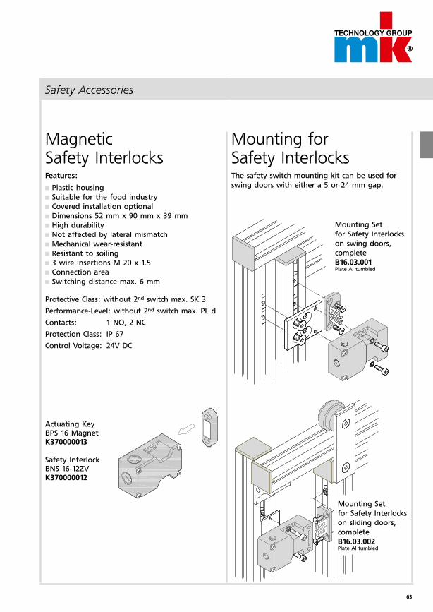
Mounting for Safety InterlocksThe safety switch mounting kit can be used for
swing doors with either a 5 or 24 mm gap.
Mounting Set
for Safety Interlocks
on sliding doors,
complete
B16.03.002Plate Al tumbled
Mounting Set
for Safety Interlocks
on swing doors,
complete
B16.03.001Plate Al tumbled
Magnetic Safety InterlocksFeatures:
Plastic housing
Suitable for the food industry
Covered installation optional
Dimensions 52 mm x 90 mm x 39 mm
High durability
Not affected by lateral mismatch
Mechanical wear-resistant
Resistant to soiling
3 wire insertions M 20 x 1.5
Connection area
Switching distance max. 6 mm
Protective Class: without 2nd switch max. SK 3
Performance-Level: without 2nd switch max. PL d
Contacts: 1 NO, 2 NC
Protection Class: IP 67
Control Voltage: 24V DC
Actuating Key BPS 16 Magnet K370000013
Safety InterlockBNS 16-12ZV K370000012
64
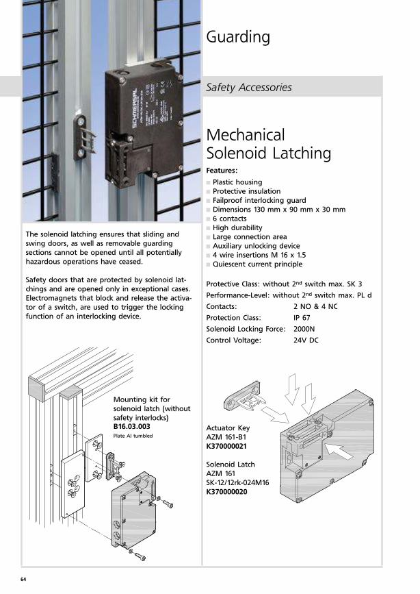
Mechanical Solenoid LatchingFeatures:
Plastic housing
Protective insulation
Failproof interlocking guard
Dimensions 130 mm x 90 mm x 30 mm
6 contacts
High durability
Large connection area
Auxiliary unlocking device
4 wire insertions M 16 x 1.5
Quiescent current principle
Protective Class: without 2nd switch max. SK 3
Performance-Level: without 2nd switch max. PL d
Contacts: 2 NO & 4 NC
Protection Class: IP 67
Solenoid Locking Force: 2000N
Control Voltage: 24V DC
Actuator Key
AZM 161-B1
K370000021
Solenoid Latch
AZM 161
SK-12/12rk-024M16
K370000020
Mounting kit for
solenoid latch (without
safety interlocks)B16.03.003Plate Al tumbled
The solenoid latching ensures that sliding and
swing doors, as well as removable guarding
sections cannot be opened until all potentially
hazardous operations have ceased.
Safety doors that are protected by solenoid lat-
chings and are opened only in exceptional cases.
Electromagnets that block and release the activa-
tor of a switch, are used to trigger the locking
function of an interlocking device.
Safety Accessories
Guarding
65
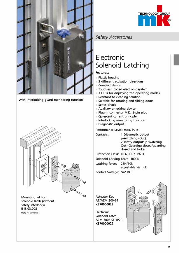
Safety Accessories
Actuator Key
AZ/AZM 300-B1
K370000023
Electronic
Solenoid Latch
AZM 300Z-ST-1P2PK370000022
Mounting kit for
solenoid latch (without
safety interlocks)B16.03.008Plate Al tumbled
Electronic Solenoid LatchingFeatures:
Plastic housing
3 different activation directions
Compact design
Touchless, coded electronic system
3 LEDs for displaying the operating modes
Resistant to cleaning solution
Suitable for rotating and sliding doors
Series circuit
Auxiliary unlocking device
Plug-in connector M12, 8-pin plug
Quiescent current principle
Interlocking monitoring function
Diagnostic output
Performance-Level: max. PL e
Contacts: 1 Diagnostic output p-switching (Out), 2 safety outputs p-switching. Out: Guarding closed/guarding closed and locked
Protection Class: IP66, IP67, IP69K
Solenoid Locking Force: 1000N
Latching force: 25N/50N adjustable via hub
Control Voltage: 24V DC
With interlocking guard monitoring function
66
q w e r t
h g f d s a
2)
;
l
k
j
i
u
y
750 1500 750 750
750 750 750 750
750
1000
1000
1000
1000
1004
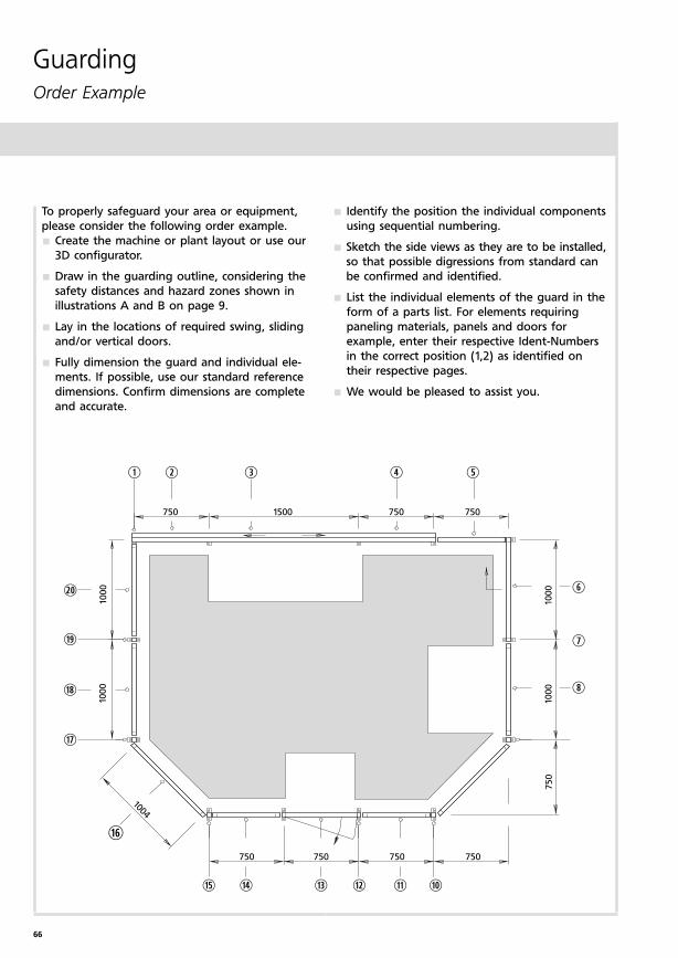
GuardingOrder Example
Identify the position the individual components
using sequential numbering.
Sketch the side views as they are to be installed,
so that possible digressions from standard can
be confirmed and identified.
List the individual elements of the guard in the
form of a parts list. For elements requiring
paneling materials, panels and doors for
example, enter their respective Ident-Numbers
in the correct position (1,2) as identified on
their respective pages.
We would be pleased to assist you.
To properly safeguard your area or equipment,
please consider the following order example.
Create the machine or plant layout or use our
3D configurator.
Draw in the guarding outline, considering the
safety distances and hazard zones shown in
illustrations A and B on page 9.
Lay in the locations of required swing, sliding
and/or vertical doors.
Fully dimension the guard and individual ele-
ments. If possible, use our standard reference
dimensions. Confirm dimensions are complete
and accurate.
67
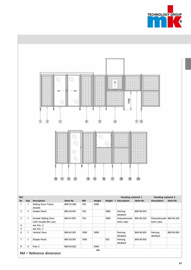
q w e r t y u i
a s d f g h j k l ; 2)
1100
Ref Paneling material 1 Paneling material 2
Nr. Qty. Description Ident-Nr. RM Height Height 1 Description Ident-Nr. Description Ident-Nr.
1 1 Sliding Door Frame B69.55.004 750 2060
double
2 5 Simple Panel B69.50.001 750 1800 Fencing B69.90.003
40x40x4
3 1 Double Sliding Door B69.61.005 750 1800 Polycarbonate B69.90.203 Polycarbonate B69.90.203
with Double Bit Lock 6mm clear 6mm clear
4 see Pos. 2
5 see Pos. 2
6 1 Vertical Door B69.62.001 1000 3000 Fencing B69.90.003 Fencing B69.90.003
40x40x4 40x40x4
7 1 Simple Panel B69.50.001 1000 920 Fencing B69.90.003
40x40x4
8 5 Post 2 B69.65.002 2060
etc.
RM = Reference dimension
68
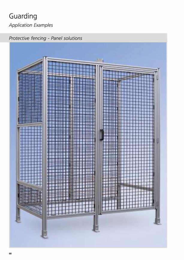
GuardingApplication Examples
Protective fencing - Panel solutions
69
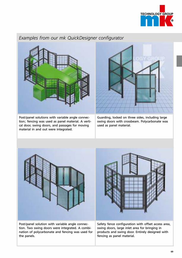
Examples from our mk QuickDesigner configurator
Post/panel solutions with variable angle connec-
tion; fencing was used as panel material. A verti-
cal door, swing doors, and passages for moving
material in and out were integrated.
Post/panel solution with variable angle connec-
tion. Two swing doors were integrated. A combi-
nation of polycarbonate and fencing was used for
the panels.
Guarding, locked on three sides, including large
swing doors with crossbeam. Polycarbonate was
used as panel material.
Safety fence configuration with offset access area,
swing doors, large inlet area for bringing in
products and swing door. Entirely designed with
fencing as panel material.
70
GuardingApplication Examples
Detail A Detail B è page 13
Detail B
Detail A
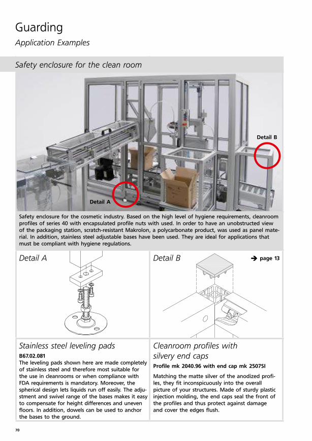
Stainless steel leveling padsB67.02.081 The leveling pads shown here are made completely
of stainless steel and therefore most suitable for
the use in cleanrooms or when compliance with
FDA requirements is mandatory. Moreover, the
spherical design lets liquids run off easily. The adju-
stment and swivel range of the bases makes it easy
to compensate for height differences and uneven
floors. In addition, dowels can be used to anchor
the bases to the ground.
Cleanroom profiles with
silvery end capsProfile mk 2040.96 with end cap mk 2507SI
Matching the matte silver of the anodized profi-
les, they fit inconspicuously into the overall
picture of your structures. Made of sturdy plastic
injection molding, the end caps seal the front of
the profiles and thus protect against damage
and cover the edges flush.
Safety enclosure for the cosmetic industry. Based on the high level of hygiene requirements, cleanroom
profiles of series 40 with encapsulated profile nuts with used. In order to have an unobstructed view
of the packaging station, scratch-resistant Makrolon, a polycarbonate product, was used as panel mate-
rial. In addition, stainless steel adjustable bases have been used. They are ideal for applications that
must be compliant with hygiene regulations.
Safety enclosure for the clean room
71
Detail A Detail B è page 55
Detail B
Detail A
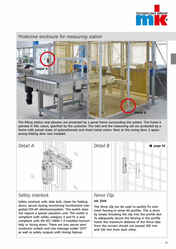
Safety interlock
Safety interlock with slide bolt, closer for folding
doors, secure closing monitoring functionand inte-
grated CES-AP electronicssystem. This switch does
not require a special valuation unit. The switch is
compliant with safety category 4 and PL e and
compliant with EN ISO 13849-1 if installed horizon-
tally or facing down. There are two secure semi
conductor outlets and one message outlet 'OUT'
as well as safety outputs with timing feature.
The lifting station and elevator are protected by a panel frame surrounding the system. The frame is
painted in RAL colors, specified by the customer. The inlet and the measuring cell are protected by a
frame with panels make of polycarbonate and sheet metal covers. Next to the swing door, a space-
saving folding door was installed.
Protective enclosure for measuring station
Fence Clip mk 2544
The fence clip can be used to quickly fix wire
mesh fencing in series 40 profiles. This is done
by simply knocking the clip into the profile slot.
To adequately secure the fencing in the profile
frame the maximum distance of the fence clips
from the corners should not exceed 200 mm
and 520 mm from each other.
72
GuardingApplication Examples
Detail A Detail B
Detail BDetail A
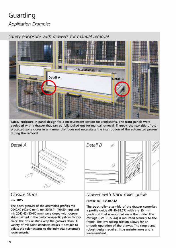
Closure Stripsmk 3015
The open grooves of the assembled profiles mk
2040.40 (40x40 mm), mk 2040.41 (40x80 mm) and
mk 2040.45 (80x80 mm) were closed with closure
strips painted in the customer-specific yellow factory
color. The closure strips keep the grooves clean. A
variety of mk paint standards makes it possible to
adjust the color accents to the individual customer's
requirements.
Drawer with track roller guide
Profile rail B51.04.142
The track roller assembly of the drawer comprises
a profile guide (PF-10-38.77) with a ø 10 mm
guide rod that is mounted on is the inside. The
carriage (LW 38.77-44) is mounted securely to the
frame. The low rolling friction allows for an
smooth operation of the drawer. The simple and
robust design requires little maintenance and is
wear-resistant.
Safety enclosure in panel design for a measurement station for crankshafts. The front panels were
equipped with a drawer that can be fully pulled out for manual removal. Thereby, the rear side of the
protected zone closes in a manner that does not necessitate the interruption of the automated process
during the removal.
Safety enclosure with drawers for manual removal
73
Detail BDetail A
Detail A
Detail B
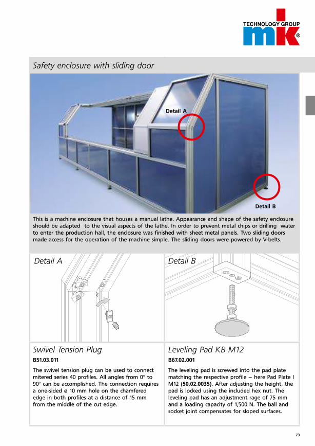
This is a machine enclosure that houses a manual lathe. Appearance and shape of the safety enclosure
should be adapted to the visual aspects of the lathe. In order to prevent metal chips or drilling water
to enter the production hall, the enclosure was finished with sheet metal panels. Two sliding doors
made access for the operation of the machine simple. The sliding doors were powered by V-belts.
Safety enclosure with sliding door
Leveling Pad KB M12B67.02.001
The leveling pad is screwed into the pad plate
matching the respective profile – here Pad Plate I
M12 (50.02.0035). After adjusting the height, the
pad is locked using the included hex nut. The
leveling pad has an adjustment rage of 75 mm
and a loading capacity of 1,500 N. The ball and
socket joint compensates for sloped surfaces.
Swivel Tension PlugB51.03.011
The swivel tension plug can be used to connect
mitered series 40 profiles. All angles from 0° to
90° can be accomplished. The connection requires
a one-sided ø 10 mm hole on the chamfered
edge in both profiles at a distance of 15 mm
from the middle of the cut edge.
74
Detail C
Detail B
Detail D
Detail A
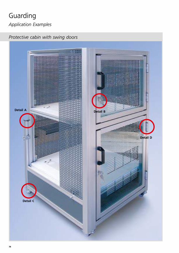
GuardingApplication Examples
Protective cabin with swing doors
75
Detail D è page 58Detail C
Detail B è page 59Detail A
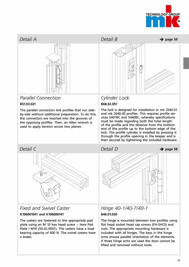
Parallel Connection B51.03.021
The parallel connectors link profiles that run side-
by-side without additional preparation. To do this,
the connectors are inserted into the grooves of
the opposing profiles. Then, an Allen wrench is
used to apply tension across two planes.
Hinge 40-1/40-7/40-1
B46.01.030
The hinge is mounted between two profiles using
flat head socket head cap screws (FH-SHCS) and
nuts. The appropriate mounting hardware is
included with all hinges. The keys in the hinge
arms ensure parallel orientation of the elements.
If three hinge arms are used the door cannot be
lifted and removed without tools.
Fixed and Swivel Caster K106001041 and K106000141
The casters are fastened to the appropriate pad
plate using an M 10 hex head screw – here Pad
Plate I M10 (50.02.0041). The casters have a load
bearing capacity of 600 N. The swivel casters have
a brake.
Cylinder Lock B68.02.051
The lock is designed for installation in mk 2040.01 and mk 2040.40 profiles. This requires profile ser-vices 5401BC and 5440BC, whereby specifications must be made regarding both the total length of the profile and the distance from the bottom end of the profile up to the bottom edge of the lock. The profile cylinder is installed by pressing it through the profile opening in the keeper and is then secured by tightening the included hardware.
76
GuardingApplication Examples
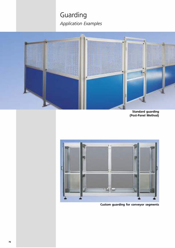
Custom guarding for conveyor segments
Standard guarding
(Post-Panel Method)
77
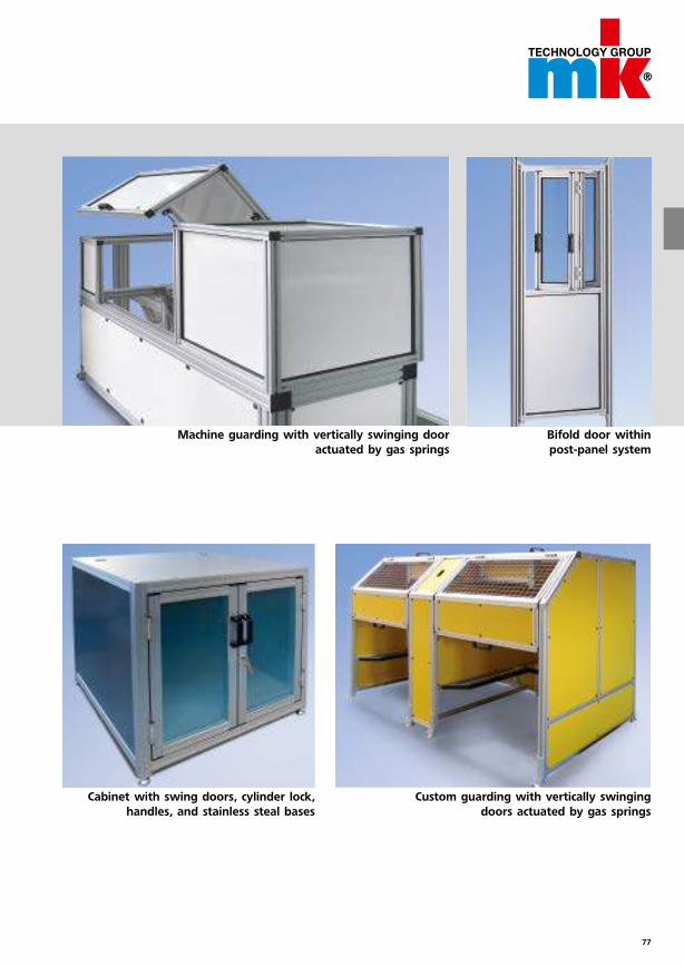
Bifold door within
post-panel system
Machine guarding with vertically swinging door
actuated by gas springs
Custom guarding with vertically swinging
doors actuated by gas springs
Cabinet with swing doors, cylinder lock,
handles, and stainless steal bases
78
GuardingApplication Examples
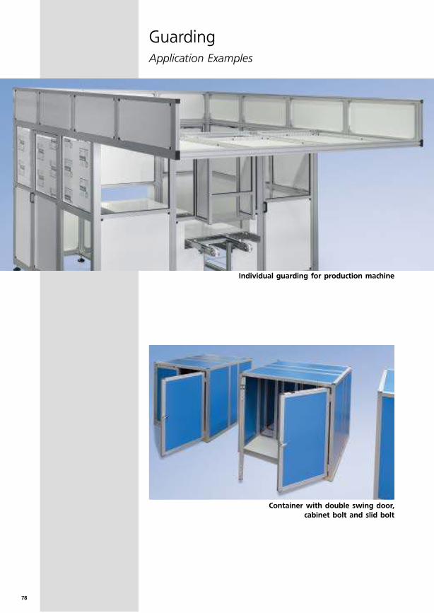
Container with double swing door,
cabinet bolt and slid bolt
Individual guarding for production machine
79
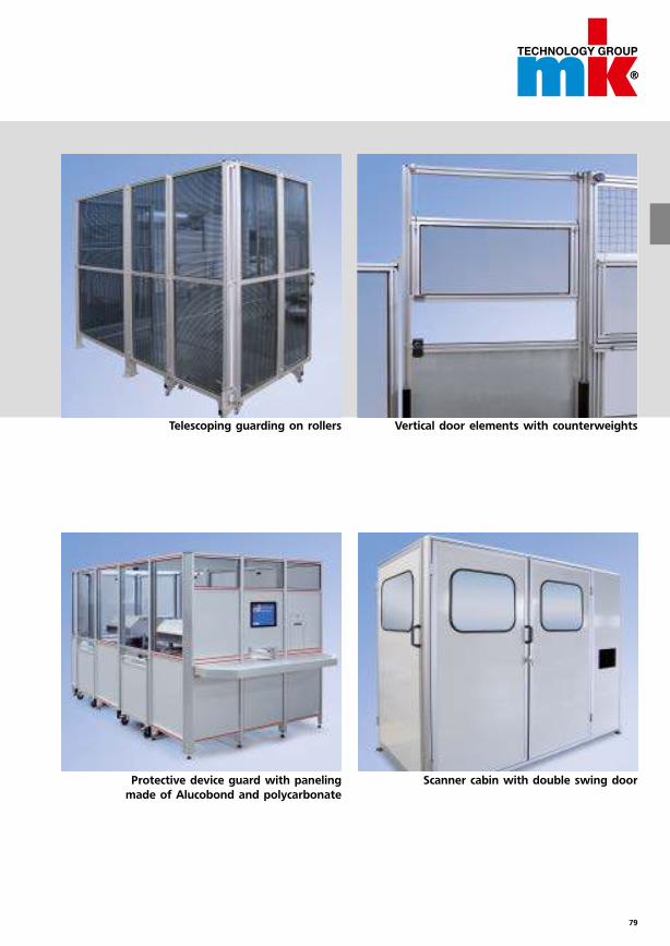
Telescoping guarding on rollers Vertical door elements with counterweights
Scanner cabin with double swing doorProtective device guard with paneling
made of Alucobond and polycarbonate
80
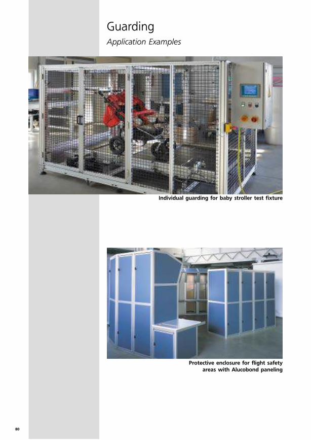
Individual guarding for baby stroller test fixture
GuardingApplication Examples
Protective enclosure for flight safety
areas with Alucobond paneling
81
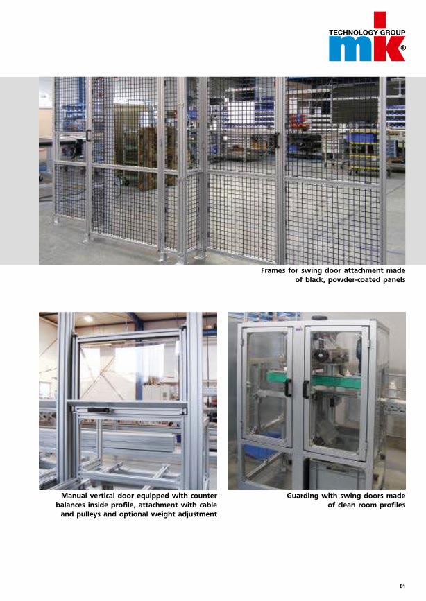
Frames for swing door attachment made
of black, powder-coated panels
Guarding with swing doors made
of clean room profiles
Manual vertical door equipped with counter
balances inside profile, attachment with cable
and pulleys and optional weight adjustment
82
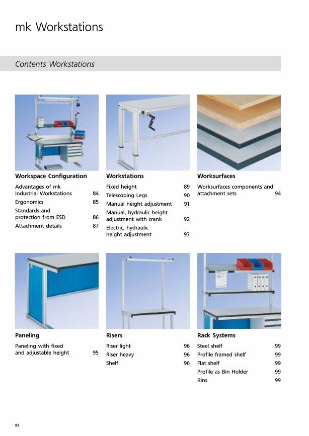
Contents Workstations
Workspace Configuration
Advantages of mk
Industrial Workstations 84
Ergonomics 85
Standards and
protection from ESD 86
Attachment details 87
Paneling
Paneling with fixed
and adjustable height 95
Workstations
Fixed height 89
Telescoping Legs 90
Manual height adjustment 91
Manual, hydraulic height
adjustment with crank 92
Electric, hydraulic
height adjustment 93
Risers
Riser light 96
Riser heavy 96
Shelf 96
Worksurfaces
Worksurfaces components and
attachment sets 94
Rack Systems
Steel shelf 99
Profile framed shelf 99
Flat shelf 99
Profile as Bin Holder 99
Bins 99
mk Workstations
83
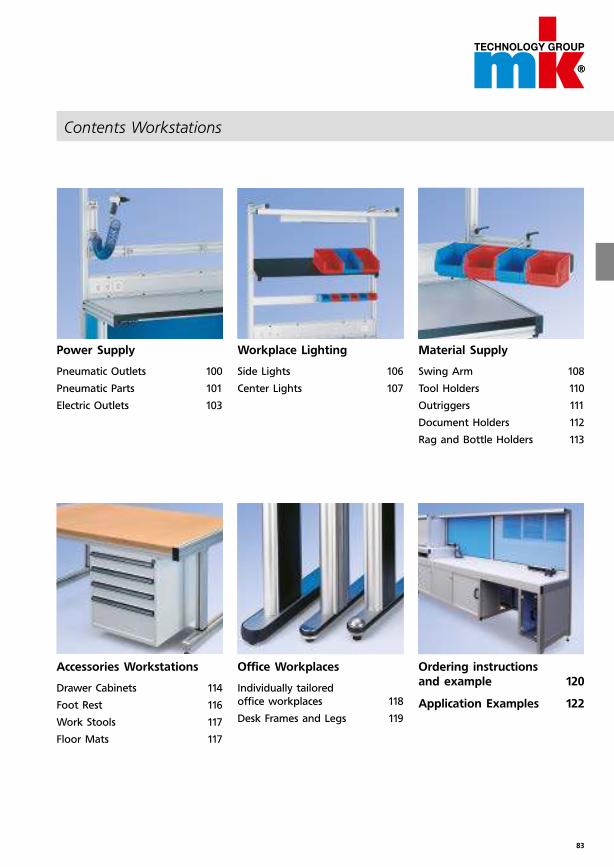
Contents Workstations
Power Supply
Pneumatic Outlets 100
Pneumatic Parts 101
Electric Outlets 103
Accessories Workstations
Drawer Cabinets 114
Foot Rest 116
Work Stools 117
Floor Mats 117
Office Workplaces
Individually tailored
office workplaces 118
Desk Frames and Legs 119
Ordering instructions
and example 120
Application Examples 122
Workplace Lighting
Side Lights 106
Center Lights 107
Material Supply
Swing Arm 108
Tool Holders 110
Outriggers 111
Document Holders 112
Rag and Bottle Holders 113
84
Workspace Configuration
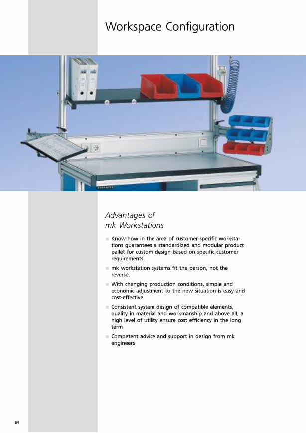
Advantages of
mk Workstations
Know-how in the area of customer-specific worksta-
tions guarantees a standardized and modular product
pallet for custom design based on specific customer
requirements.
mk workstation systems fit the person, not the
reverse.
With changing production conditions, simple and
economic adjustment to the new situation is easy and
cost-effective
Consistent system design of compatible elements,
quality in material and workmanship and above all, a
high level of utility ensure cost efficiency in the long
term
Competent advice and support in design from mk
engineers
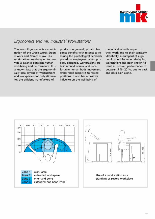
85
H =
1050
80 -
300
Ergonomics and mk Industrial Workstations
The word Ergonomics is a combi-
nation of the Greek words Ergon
= work and Nomos = law. Our
workstations are designed to pro-
vide a balance between human
well-being and performance. It is
a known fact that the ergonomi-
cally ideal layout of workstations
and workplaces not only stimula-
tes the efficient manufacture of
products in general, yet also has
direct benefits with respect to re-
ducing the psychological demands
placed on employees. When pro-
perly designed, workstations are
built around normal and com-
fortable human body movement
rather than subject it to forced
positions. It also has a positive
influence on the well-being of
the individual with respect to
their work and to their company.
Sta tistically, a disregard of ergo-
nomic principles when designing
workstations has been shown to
result in reduced performance of
between 5 %- 20 %, due to back
and neck pain alone.
Zone 1 work area
Zone 2 extended workspace
Zone 3 one-hand zone
Zone 4 extended one-hand zone
Use of a workstation as a
standing or seated workplace

86
Standards and protection from ESD
Workspace Configuration
Standards and Practicesmk has used the following Standards and Practi-
ces as a basis for it’s designs:
BGI 523; Person and workplace
DIN 31000/A1; VDE 1000/A1; general principals
for safe design of technical products
DIN EN 527-1/-2/-3; Office furniture, office and
work desks
DIN EN 894-1/-2/-3; Safety of machinery –
Ergonomic requirements for the design of dis-
plays and control actuators
DIN EN ISO 6385; Ergonomic principles in the
design of work systems
DIN EN ISO 10075-1/-2/-3; Ergonomic principles
related to mental work-load
DIN VDE 0100-410; VDE 0100-410; Construction
of low-voltage power systems, protective
measures – protection against electric shock
Electricity and GroundingIf workplaces are electrified (i.e. lighting, electrical
outlets, etc.), DIN VDE 0100-410 requires that all
conductive elements of the workplace must be
connected via a common ground, so that the
work place remains safe in the case of an electrical
short.
As a rule, mk uses a grounding method in all it’s
standard workstation systems which is applied
whether the workstation has electrical compon-
ents or not. Connecting angles using our PE-Nuts,
this grounding is accomplished without the use of
additional wires. This means that in the case of
later electric additions, that only the electrical
grounding must be connected with the work-
place.
Angle connection with ESD-NutsThe nut is stamped to include protrusions which
break through the anodized surface of the pro-
file. This provides conductivity through the screw
and thus ensures grounding of the connection.
Common Grounding
mk WorkstationsA defined grounding location of an mk workplace
for attachment to a common ground.
Nut 1 M8 PE 34.01.0018
SHCS M8x16 D0912816
Angle Al
Ground-
connectionB02.99.151
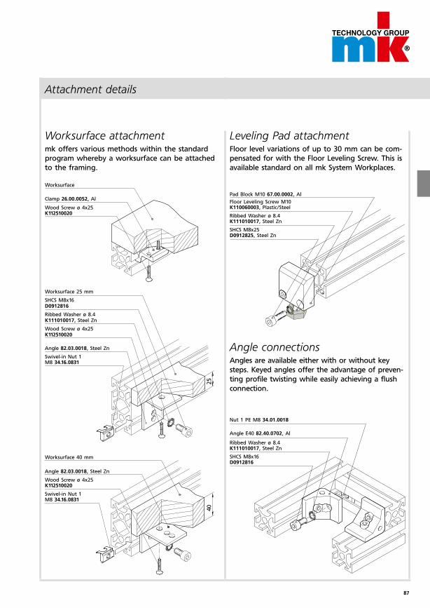
87
25
40
Attachment details
Worksurface attachmentmk offers various methods within the standard
program whereby a worksurface can be attached
to the framing.
Worksurface
Clamp 26.00.0052, Al
Wood Screw ø 4x25 K112510020
Leveling Pad attachmentFloor level variations of up to 30 mm can be com-
pensated for with the Floor Leveling Screw. This is
available standard on all mk System Workplaces.
Pad Block M10 67.00.0002, Al
Floor Leveling Screw M10K110060003, Plastic/Steel
Ribbed Washer ø 8.4K111010017, Steel Zn
SHCS M8x25D0912825, Steel Zn
Angle connectionsAngles are available either with or without key
steps. Keyed angles offer the advantage of preven-
ting profile twisting while easily achieving a flush
connection.
Nut 1 PE M8 34.01.0018
Angle E40 82.40.0702, Al
Ribbed Washer ø 8.4K111010017, Steel Zn
SHCS M8x16D0912816
Worksurface 25 mm
SHCS M8x16D0912816
Ribbed Washer ø 8.4K111010017, Steel Zn
Wood Screw ø 4x25K112510020
Angle 82.03.0018, Steel Zn
Swivel-in Nut 1 M8 34.16.0831
Worksurface 40 mm
Angle 82.03.0018, Steel Zn
Wood Screw ø 4x25 K112510020
Swivel-in Nut 1 M8 34.16.0831
88
Workstations
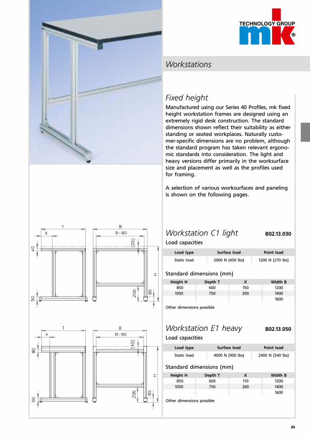
89
Workstations
Fixed heightManufactured using our Series 40 Profiles, mk fixed
height workstation frames are designed using an
extremely rigid desk construction. The standard
dimensions shown reflect their suitability as either
standing or seated workplaces. Naturally custo-
mer-specific dimensions are no problem, although
the standard program has taken relevant ergono-
mic standards into consideration. The light and
heavy versions differ primarily in the worksurface
size and placement as well as the profiles used
for framing.
A selection of various worksurfaces and paneling
is shown on the following pages.
Load type Surface load Point load
Static load 2000 N (450 lbs) 1200 N (270 lbs)
Load type Surface load Point load
Static load 4000 N (900 lbs) 2400 N (540 lbs)
Height H Depth T X Width B
850 600 150 1200
1050 750 300 1400
1600
Height H Depth T X Width B
850 600 110 1200
1050 750 260 1400
1600
Workstation C1 light B02.13.030
Load capacities
Workstation E1 heavy B02.13.050
Load capacities
Standard dimensions (mm)
Other dimensions possible
Standard dimensions (mm)
Other dimensions possible

90
Workstations
Telescoping Legs
Profile mk 2040.75
and mk 2040.01
Profile mk 2040.75
and mk 2040.36
Profile mk 2040.74
and mk 2040.36
Profile mk 2040.74
and mk 2040.01
SHCS M8x16, D0912816
Ribbed Washer ø 8.4, K111010017, Steel Zn
Nut 1 PE M8 34.01.0018
SHCS M8x16, D0912816
Attachment Plate (upper)left 50.09.0070 right 50.09.0071
Nut 1 PE M8 34.01.0018
SHCS M8x16, D0912816
SHCS M8x16, D0912816
Attachment Plate (lower)50.09.0072
Nut 1 PE M8 34.01.0018
Guide mk 2538, PPN 1060
Ribbed Washer ø 5.3, K111010015, Steel Zn
SHCS M5x16, D0912516
Telescoping Profiles
for manual height adjustment
Telescoping Profiles
for electric height adjustment
Workstations
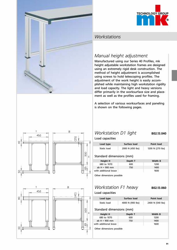
91
Workstations
Manual height adjustment Manufactured using our Series 40 Profiles, mk
height adjustable workstation frames are designed
using an extremely rigid desk construction. The
method of height adjustment is accomplished
using screws to hold telescoping profiles. The
adjustment of the work height is easily accom-
plished while main taining high workstation rigidity
and load capacity. The light and heavy versions
differ primarily in the worksurface size and place-
ment as well as the profiles used for framing.
A selection of various worksurfaces and paneling
is shown on the following pages.
Load type Surface load Point load
Static load 2000 N (450 lbs) 1200 N (270 lbs)
Load type Surface load Point load
Static load 4000 N (900 lbs) 2400 N (540 lbs)
Height H Depth T Width B
680 to 1070 600 1200
ab H = 900 mm 750 1400
with additional brace 1600
Height H Depth T Width B
680 to 1070 600 1200
ab H = 900 mm 750 1400
with additional brace 1600
Workstation D1 light B02.13.040
Load capacities
Workstation F1 heavy B02.13.060
Load capacities
Standard dimensions (mm)
Other dimensions possible
Standard dimensions (mm)
Other dimensions possible
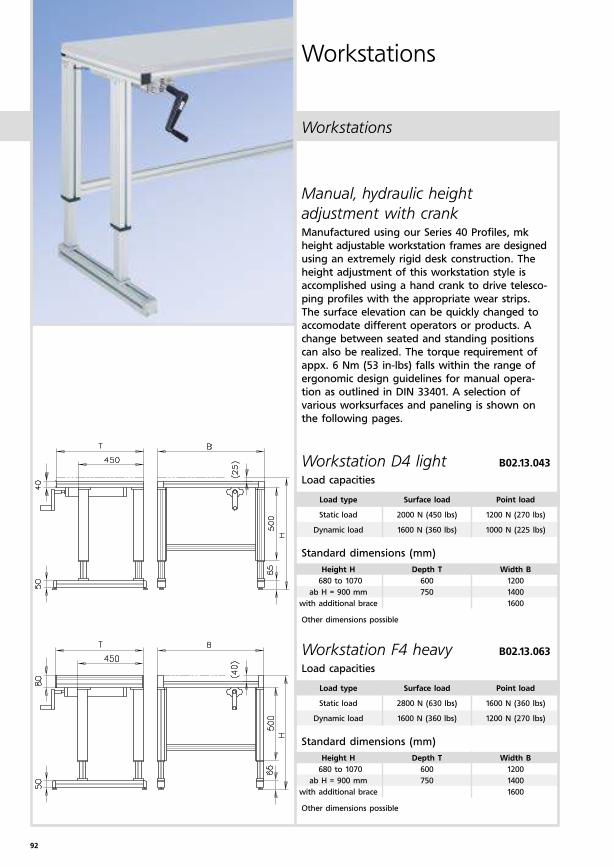
92
Workstations
Workstations
Manual, hydraulic height
adjustment with crankManufactured using our Series 40 Profiles, mk
height adjustable workstation frames are designed
using an extremely rigid desk construction. The
height adjustment of this workstation style is
accomplished using a hand crank to drive telesco-
ping profiles with the appropriate wear strips.
The surface elevation can be quickly changed to
accomodate different operators or products. A
change between seated and standing positions
can also be realized. The torque requirement of
appx. 6 Nm (53 in-lbs) falls within the range of
ergonomic design guidelines for manual opera-
tion as outlined in DIN 33401. A selection of
various worksurfaces and paneling is shown on
the following pages.
Workstation D4 light B02.13.043
Load capacities
Workstation F4 heavy B02.13.063
Load capacities
Standard dimensions (mm)
Standard dimensions (mm)
Load type Surface load Point load
Static load 2000 N (450 lbs) 1200 N (270 lbs)
Dynamic load 1600 N (360 lbs) 1000 N (225 lbs)
Load type Surface load Point load
Static load 2800 N (630 lbs) 1600 N (360 lbs)
Dynamic load 1600 N (360 lbs) 1200 N (270 lbs)
Height H Depth T Width B
680 to 1070 600 1200
ab H = 900 mm 750 1400
with additional brace 1600
Height H Depth T Width B
680 to 1070 600 1200
ab H = 900 mm 750 1400
with additional brace 1600
Other dimensions possible
Other dimensions possible
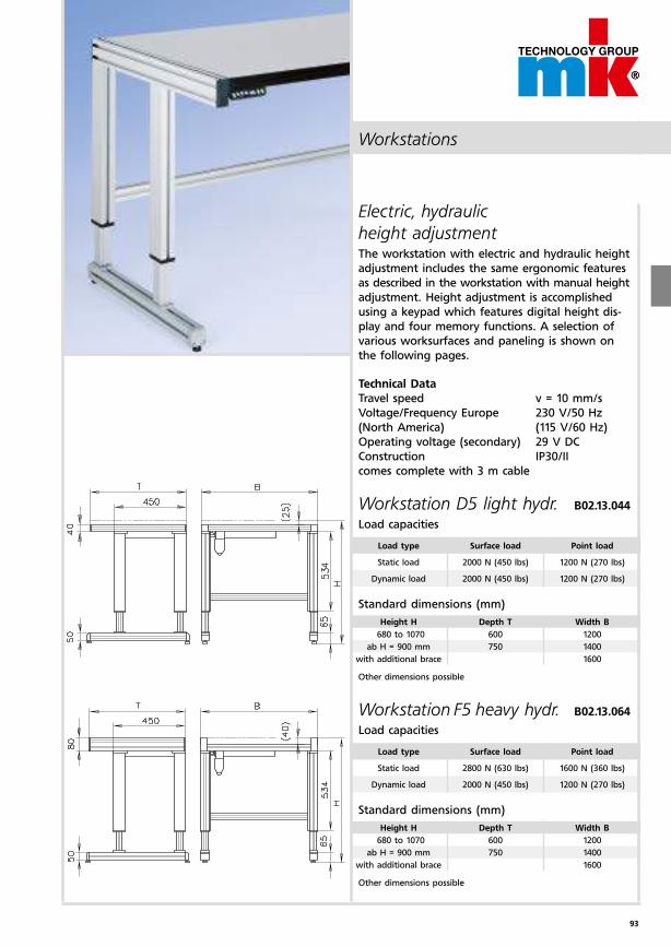
93
Workstations
Electric, hydraulic
height adjustment The workstation with electric and hydraulic height
adjustment includes the same ergonomic features
as described in the workstation with manual height
adjustment. Height adjustment is accomplished
using a keypad which features digital height dis-
play and four memory functions. A selection of
various worksurfaces and paneling is shown on
the following pages.
Technical Data
Travel speed v = 10 mm/s
Voltage/Frequency Europe 230 V/50 Hz
(North America) (115 V/60 Hz)
Operating voltage (secondary) 29 V DC
Construction IP30/II
comes complete with 3 m cable
Workstation D5 light hydr. B02.13.044
Load capacities
Workstation F5 heavy hydr. B02.13.064
Load capacities
Standard dimensions (mm)
Standard dimensions (mm)
Load type Surface load Point load
Static load 2000 N (450 lbs) 1200 N (270 lbs)
Dynamic load 2000 N (450 lbs) 1200 N (270 lbs)
Load type Surface load Point load
Static load 2800 N (630 lbs) 1600 N (360 lbs)
Dynamic load 2000 N (450 lbs) 1200 N (270 lbs)
Height H Depth T Width B
680 to 1070 600 1200
ab H = 900 mm 750 1400
with additional brace 1600
Height H Depth T Width B
680 to 1070 600 1200
ab H = 900 mm 750 1400
with additional brace 1600
Other dimensions possible
Other dimensions possible
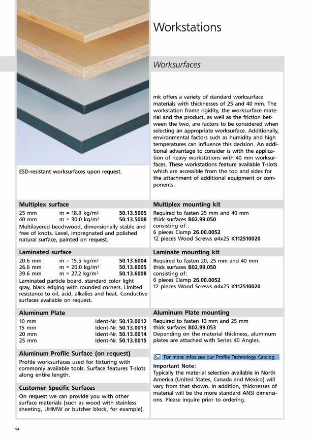
94
Worksurfaces
Workstations
mk offers a variety of standard worksurface
ma terials with thicknesses of 25 and 40 mm. The
workstation frame rigidity, the worksurface mate-
rial and the product, as well as the friction bet-
ween the two, are factors to be considered when
selecting an appropriate worksurface. Additionally,
environmental factors such as humidity and high
temperatures can influence this decision. An addi-
tional advantage to consider is with the applica-
tion of heavy workstations with 40 mm worksur-
faces. These workstations feature available T-slots
which are accessible from the top and sides for
the attachment of additional equipment or com-
ponents.
Multiplex surface
25 mm m = 18.9 kg/m2 50.13.500540 mm m = 30.0 kg/m2 50.13.5008
Multilayered beechwood, dimensionally stable and free of knots. Level, impregnated and polished natural surface, painted on request.
Laminated surface
20.6 mm m = 15.5 kg/m2 50.13.600426.6 mm m = 20.0 kg/m2 50.13.600539.6 mm m = 27.2 kg/m2 50.13.6008
Laminated particle board, standard color light gray, black edging with rounded corners. Limited resistance to oil, acid, alkalies and heat. Conductive surfaces available on request.
Aluminum Plate
10 mm Ident-Nr. 50.13.001215 mm Ident-Nr. 50.13.001320 mm Ident-Nr. 50.13.001425 mm Ident-Nr. 50.13.0015
Aluminum Profile Surface (on request)
Profile worksurfaces used for fixturing with commonly available tools. Surface features T-slots along entire length.
Customer Specific Surfaces
On request we can provide you with other surface materials (such as wood with stainless sheeting, UHMW or butcher block, for example).
Multiplex mounting kit
Required to fasten 25 mm and 40 mm thick surfaces B02.99.050consisting of:: 6 pieces Clamp 26.00.005212 pieces Wood Screws ø4x25 K112510020
Laminate mounting kit
Required to fasten 20, 25 mm and 40 mm thick surfaces B02.99.050consisting of: 6 pieces Clamp 26.00.005212 pieces Wood Screws ø4x25 K112510020
Aluminum Plate mounting
Required to fasten 10 mm and 25 mm thick surfaces B02.99.053Depending on the material thickness, aluminum plates are attached with Series 40 Angles.
Important Note:
Typically the material selection available in North
America (United States, Canada and Mexico) will
vary from that shown. In addition, thicknesses of
material will be the more standard ANSI dimensi-
ons. Please inquire prior to ordering.
For more infos see our Profile Technology Catalog
ESD-resistant worksurfaces upon request.
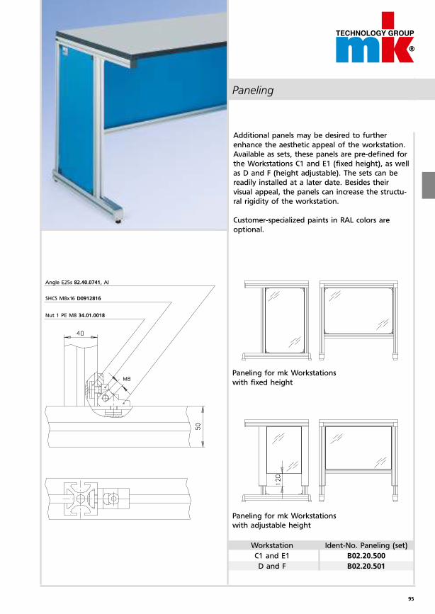
95
Paneling
Additional panels may be desired to further
enhance the aesthetic appeal of the workstation.
Available as sets, these panels are pre-defined for
the Workstations C1 and E1 (fixed height), as well
as D and F (height adjustable). The sets can be
readily installed at a later date. Besides their
visual appeal, the panels can increase the structu-
ral rigidity of the workstation.
Customer-specialized paints in RAL colors are
optional.
Paneling for mk Workstations
with fixed height
Paneling for mk Workstations
with adjustable height
Angle E25s 82.40.0741, Al
SHCS M8x16 D0912816
Nut 1 PE M8 34.01.0018
Workstation Ident-No. Paneling (set)
C1 and E1 B02.20.500
D and F B02.20.501
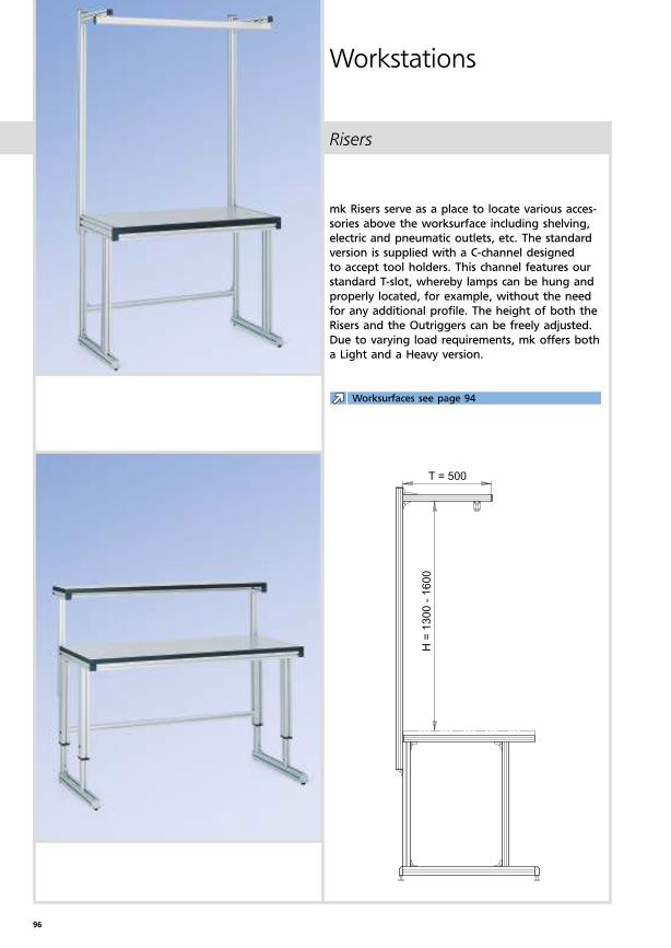
96
Risers
Workstations
mk Risers serve as a place to locate various acces-
sories above the worksurface including shelving,
electric and pneumatic outlets, etc. The standard
version is supplied with a C-channel designed
to accept tool holders. This channel features our
standard T-slot, whereby lamps can be hung and
properly located, for example, without the need
for any additional profile. The height of both the
Risers and the Outriggers can be freely adjusted.
Due to varying load requirements, mk offers both
a Light and a Heavy version.
Worksurfaces see page 94
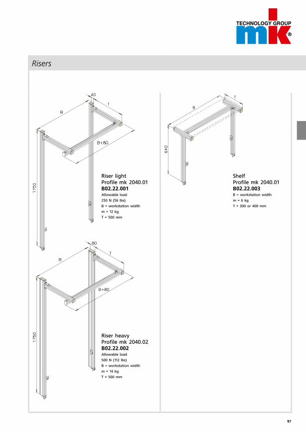
97
Risers
Riser lightProfile mk 2040.01B02.22.001Allowable load
250 N (56 lbs)
B = workstation width
m = 12 kg
T = 500 mm
ShelfProfile mk 2040.01B02.22.003B = workstation width
m = 6 kg
T = 300 or 400 mm
Riser heavyProfile mk 2040.02B02.22.002Allowable load
500 N (112 lbs)
B = workstation width
m = 14 kg
T = 500 mm
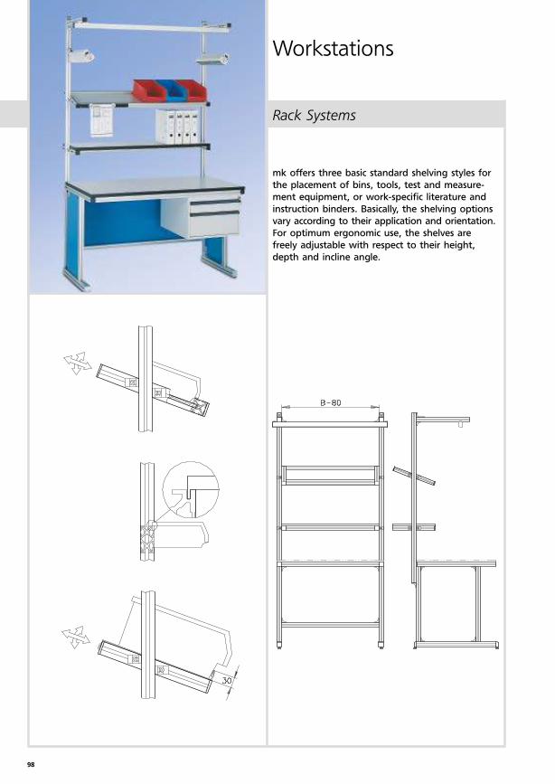
98
Rack Systems
Workstations
mk offers three basic standard shelving styles for
the placement of bins, tools, test and measure-
ment equipment, or work-specific literature and
instruction binders. Basically, the shelving options
vary according to their application and orientation.
For optimum ergonomic use, the shelves are
freely adjustable with respect to their height,
depth and incline angle.
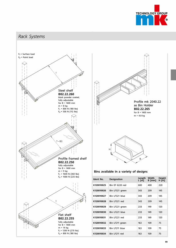
99
Rack Systems
Steel shelf B02.22.260black powder coated,
fully adjustable
for B = 1400 mm
m = 8 kg
Fs = 800 N (180 lbs)
Fp = 500 N (112 lbs)
Profile mk 2040.22as Bin HolderB02.22.265for B = 1400 mm
m = 4.8 kg
Fs = Surface load
Fp = Point load
Flat shelf B02.22.255fully adjustable
for B = 1400 mm
m = 14 kg
Fs = 1200 N (270 lbs)
Fp = 800 N (180 lbs)
Profile framed shelfB02.22.250fully adjustable
for B = 1400 mm
m = 9 kg
Fs = 1600 N (360 lbs)
Fp = 1000 N (225 lbs)
Bins available in a variety of designs
Ident No. DesignationLengthL [m]
WidthB [mm]
HeightH [m]
K120010025 Bin EF 6220 red 600 400 220
K120010026 Bin LF321 green 343 209 145
K120010027 Bin LF321 blue 343 209 145
K120010028 Bin LF321 red 343 209 145
K120010029 Bin LF221 green 233 149 120
K120010030 Bin LF221 blue 233 149 120
K120010031 Bin LF221 red 233 149 120
K120010032 Bin LF211 green 163 109 75
K120010033 Bin LF211 blue 163 109 75
K120010034 Bin LF211 red 163 109 75
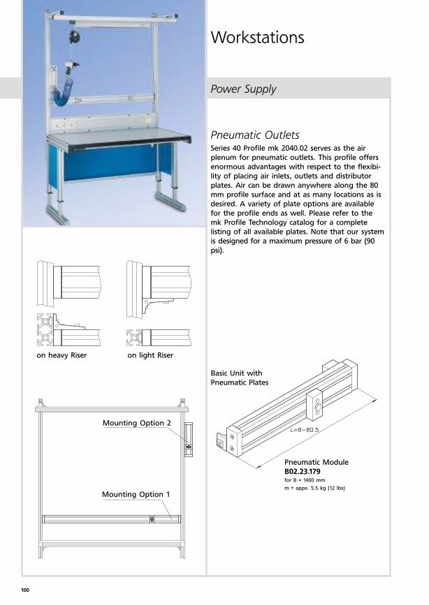
100
Power Supply
Workstations
Pneumatic OutletsSeries 40 Profile mk 2040.02 serves as the air
plenum for pneumatic outlets. This profile offers
enormous advantages with respect to the flexibi-
lity of placing air inlets, outlets and distributor
plates. Air can be drawn anywhere along the 80
mm profile surface and at as many locations as is
desired. A variety of plate options are available
for the profile ends as well. Please refer to the
mk Profile Technology catalog for a complete
listing of all available plates. Note that our system
is designed for a maximum pressure of 6 bar (90
psi).
on heavy Riser on light Riser
Mounting Option 2
Mounting Option 1
Pneumatic Module
B02.23.179for B = 1400 mm
m = appx. 5.5 kg (12 lbs)
Basic Unit with
Pneumatic Plates
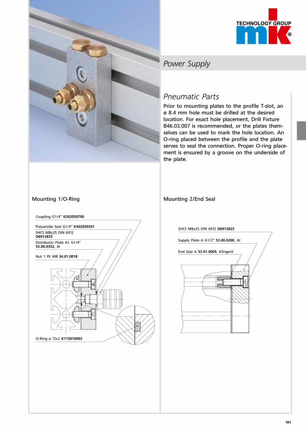
101
Power Supply
Pneumatic PartsPrior to mounting plates to the profile T-slot, an
ø 8.4 mm hole must be drilled at the desired
location. For exact hole placement, Drill Fixture
B46.03.007 is recommended, or the plates them-
selves can be used to mark the hole location. An
O-ring placed between the profile and the plate
serves to seal the connection. Proper O-ring place-
ment is ensured by a groove on the underside of
the plate.
Mounting 2/End Seal
SHCS M8x25 DIN 6912 D6912825
Supply Plate A G1/2“ 53.00.0200, Al
End Seal A 53.01.0005, Klingerit
Coupling G1/4“ K502050700
Polyamide Seal G1/4“ K502050351
SHCS M8x25 DIN 6912 D6912825
Distributor Plate A1 G1/4“ 53.00.0352, Al
Nut 1 PE M8 34.01.0018
O-Ring ø 12x2 K115010093
Mounting 1/O-Ring
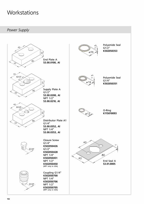
102
G1/2"
G1/4"
G1/4"
G1/4"
Power Supply
Workstations
Polyamide SealG1/2“K502050353
Polyamide SealG1/4“K502050351
O-RingK115010093
End Seal A53.01.0005
End Plate A53.00.0100, Al
Supply Plate A G1/2“53.00.0200, AlNPT 1/2“53.00.0210, Al
Distributor Plate A1G1/4“53.00.0352, AlNPT 1/4“53.00.0353, Al
Closure Screw G1/4“K502050426G1/2“K502050428NPT 1/4“K502050451NPT 1/2“K502050450(NPT only in USA)
Coupling G1/4“K502050700NPT 1/4“K502050706NPT 1/2“K502050705(NPT only in USA)
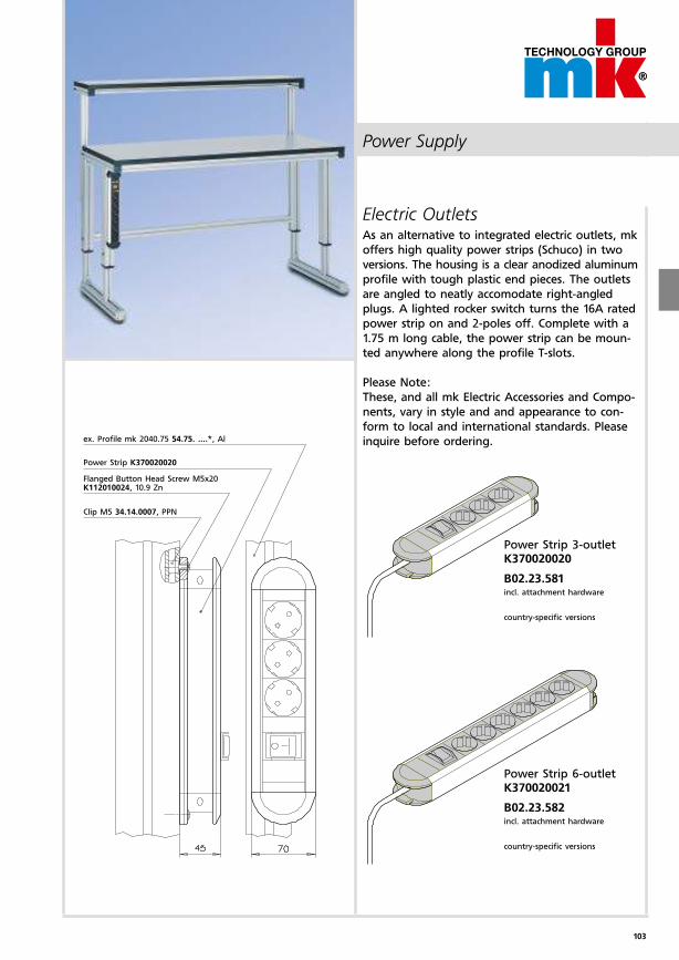
103
Power Supply
Electric OutletsAs an alternative to integrated electric outlets, mk
offers high quality power strips (Schuco) in two
versions. The housing is a clear anodized alumi num
profile with tough plastic end pieces. The outlets
are angled to neatly accomodate right-angled
plugs. A lighted rocker switch turns the 16A rated
power strip on and 2-poles off. Complete with a
1.75 m long cable, the power strip can be moun-
ted anywhere along the profile T-slots.
Please Note:
These, and all mk Electric Accessories and Compo-
nents, vary in style and and appearance to con-
form to local and international standards. Please
inquire before ordering.
Power Strip 6-outletK370020021
B02.23.582incl. attachment hardware
country-specific versions
Power Strip 3-outletK370020020
B02.23.581incl. attachment hardware
country-specific versions
ex. Profile mk 2040.75 54.75. ....*, Al
Power Strip K370020020
Flanged Button Head Screw M5x20K112010024, 10.9 Zn
Clip M5 34.14.0007, PPN
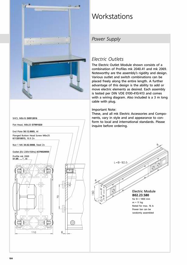
104
Power Supply
Workstations
Electric OutletsThe Electric Outlet Module shown consists of a
combination of Profiles mk 2040.41 and mk 2069.
Noteworthy are the assembly’s rigidity and design.
Various outlet and switch combinations can be
placed freely along the entire length. A further
advantage of this design is the ability to add or
move electric elements as desired. Each assembly
is tested per DIN VDE 0100-410/413 and comes
with a wiring diagram. Also included is a 3 m long
cable with plug.
Important Note:
These, and all mk Electric Accessories and Compo-
nents, vary in style and and appearance to con-
form to local and international standards. Please
inquire before ordering.
Electric ModuleB02.23.580for B = 1400 mm
m = 11 kg
Rated for max. 16 A
Power bar can be
randomly assembled
SHCS, M8x16 D0912816
Flat Head, M8x20 D7991820
End Plate 50.12.0005, Al
Flanged Button Head Screw M6x25
K112010015, 10.9 Zn
Nut 1 M6 34.02.0008, Steel Zn
Outlet (EU 230V/50Hz) K370020050
Profile mk 206951.69. ....*, Al
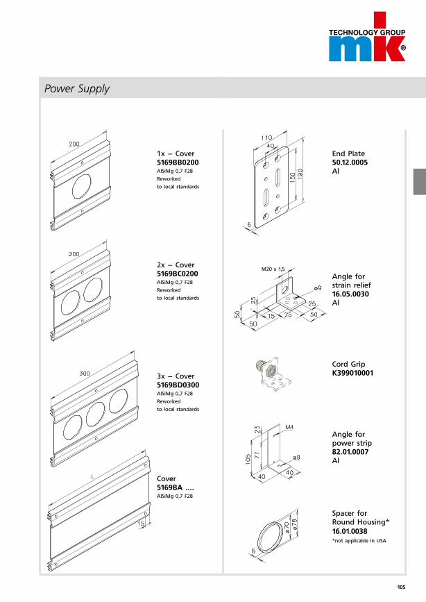
105
M20 x 1,5
Power Supply
1x – Cover5169BB0200AlSiMg 0,7 F28
Reworked
to local standards
2x – Cover5169BC0200AlSiMg 0,7 F28
Reworked
to local standards
3x – Cover5169BD0300AlSiMg 0,7 F28
Reworked
to local standards
Cover5169BA ....AlSiMg 0,7 F28
End Plate50.12.0005Al
Angle for strain relief16.05.0030Al
Cord GripK399010001
Angle for power strip82.01.0007Al
Spacer for Round Housing*
16.01.0038*not applicable in USA
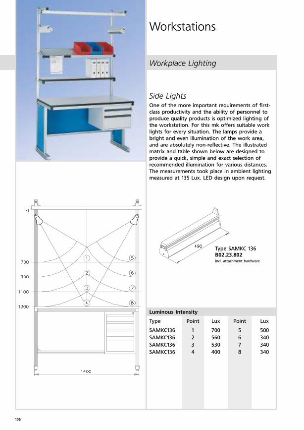
106
Workplace Lighting
Workstations
Side LightsOne of the more important requirements of first-
class productivity and the ability of personnel to
produce quality products is optimized lighting of
the workstation. For this mk offers suitable work
lights for every situation. The lamps provide a
bright and even illumination of the work area,
and are absolutely non-reflective. The illustrated
matrix and table shown below are designed to
provide a quick, simple and exact selection of
recommended illumination for various distances.
The measurements took place in ambient lighting
measured at 135 Lux. LED design upon request.
Type SAMKC 136B02.23.802incl. attachment hardware
Luminous Intensity
Type Point Lux Point Lux
SAMKC136 1 700 5 500
SAMKC136 2 560 6 340
SAMKC136 3 530 7 340
SAMKC136 4 400 8 340
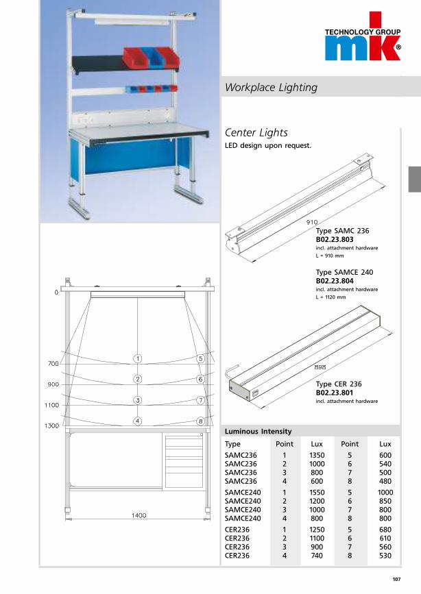
107
Workplace Lighting
Type SAMC 236B02.23.803incl. attachment hardware
L = 910 mm
Type SAMCE 240B02.23.804incl. attachment hardware
L = 1120 mm
Type CER 236B02.23.801incl. attachment hardware
Center LightsLED design upon request.
Luminous Intensity
Type Point Lux Point Lux
SAMC236 1 1350 5 600SAMC236 2 1000 6 540SAMC236 3 800 7 500SAMC236 4 600 8 480
SAMCE240 1 1550 5 1000SAMCE240 2 1200 6 850SAMCE240 3 1000 7 800SAMCE240 4 800 8 800
CER236 1 1250 5 680CER236 2 1100 6 610CER236 3 900 7 560CER236 4 740 8 530
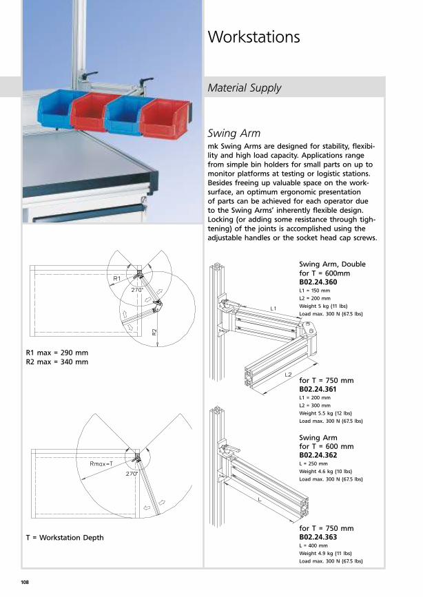
108
Material Supply
Workstations
R1 max = 290 mm
R2 max = 340 mm
T = Workstation Depth
Swing Arm, Double
for T = 600mmB02.24.360L1 = 150 mm
L2 = 200 mm
Weight 5 kg (11 lbs)
Load max. 300 N (67.5 lbs)
for T = 750 mmB02.24.361L1 = 200 mm
L2 = 300 mm
Weight 5.5 kg (12 lbs)
Load max. 300 N (67.5 lbs)
Swing Arm for T = 600 mmB02.24.362L = 250 mm
Weight 4.6 kg (10 lbs)
Load max. 300 N (67.5 lbs)
for T = 750 mmB02.24.363L = 400 mm
Weight 4.9 kg (11 lbs)
Load max. 300 N (67.5 lbs)
Swing Armmk Swing Arms are designed for stability, flexibi-
lity and high load capacity. Applications range
from simple bin holders for small parts on up to
monitor platforms at testing or logistic stations.
Besides freeing up valuable space on the work-
surface, an optimum ergonomic presentation
of parts can be achieved for each operator due
to the Swing Arms’ inherently flexible design.
Locking (or adding some resistance through tigh-
tening) of the joints is accomplished using the
adjustable handles or the socket head cap screws.
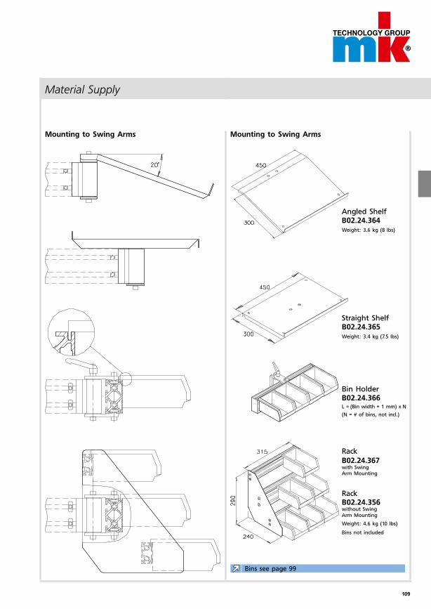
109
Material Supply
Mounting to Swing Arms Mounting to Swing Arms
Angled ShelfB02.24.364Weight: 3.6 kg (8 lbs)
Straight Shelf B02.24.365Weight: 3.4 kg (7.5 lbs)
Bin HolderB02.24.366L = (Bin width + 1 mm) x N
(N = # of bins, not incl.)
Rack
B02.24.367with Swing Arm Mounting
RackB02.24.356without Swing Arm Mounting
Weight: 4.6 kg (10 lbs)
Bins not included
Bins see page 99
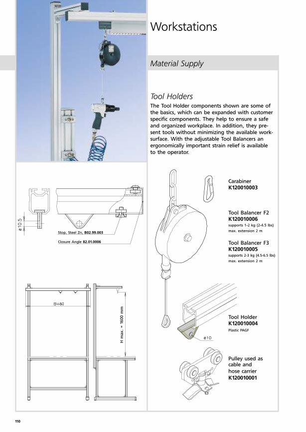
110
Material Supply
Workstations
Tool HoldersThe Tool Holder components shown are some of
the basics, which can be expanded with customer
specific components. They help to ensure a safe
and organized workplace. In addition, they pre-
sent tools without minimizing the available work-
surface. With the adjustable Tool Balancers an
ergonomically important strain relief is available
to the operator.
CarabinerK120010003
Tool Balancer F2K120010006supports 1-2 kg (2-4.5 lbs)
max. extension 2 m
Tool Balancer F3K120010005supports 2-3 kg (4.5-6.5 lbs)
max. extension 2 m
Tool HolderK120010004Plastic PAGF
Pulley used as cable and
hose carrier
K120010001
Stop, Steel Zn, B02.99.003
Closure Angle 82.01.0006
H m
ax.
= 1
600 m
m
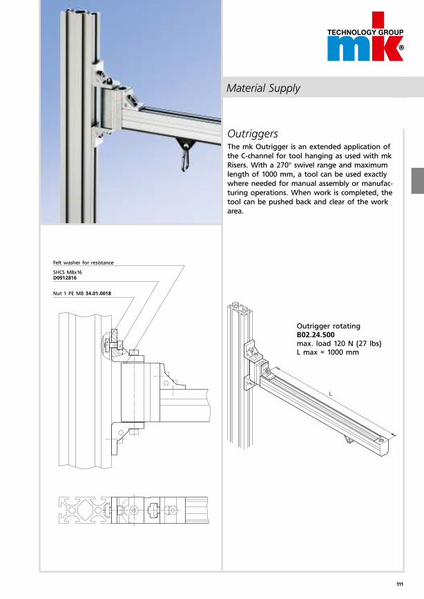
111
Material Supply
OutriggersThe mk Outrigger is an extended application of
the C-channel for tool hanging as used with mk
Risers. With a 270° swivel range and maximum
length of 1000 mm, a tool can be used exactly
where needed for manual assembly or manufac-
turing operations. When work is completed, the
tool can be pushed back and clear of the work
area.
Felt washer for resistance
SHCS M8x16D0912816
Nut 1 PE M8 34.01.0018
Outrigger rotatingB02.24.500max. load 120 N (27 lbs)L max = 1000 mm
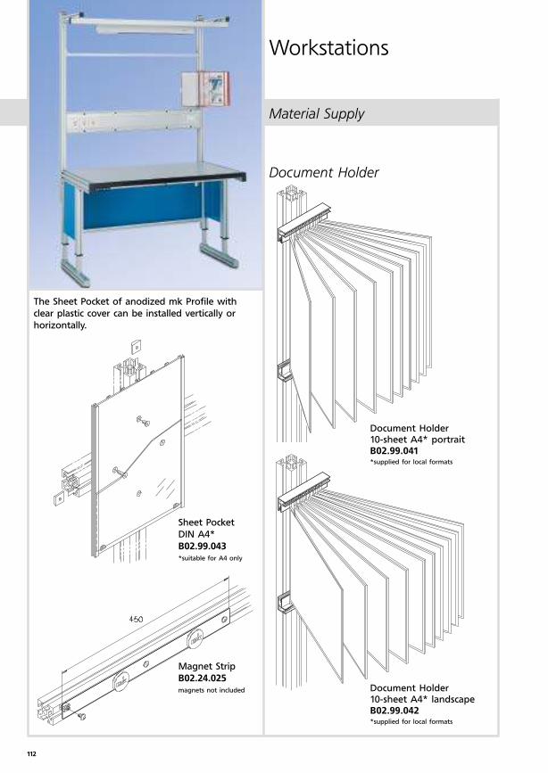
112
Material Supply
Workstations
The Sheet Pocket of anodized mk Profile with
clear plastic cover can be installed vertically or
horizontally.
Document Holder 10-sheet A4* portraitB02.99.041*supplied for local formats
Document Holder 10-sheet A4* landscapeB02.99.042*supplied for local formats
Sheet Pocket
DIN A4*
B02.99.043*suitable for A4 only
Magnet Strip
B02.24.025magnets not included
Document Holder
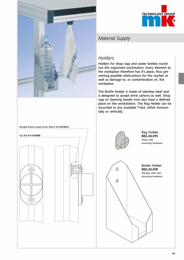
113
Material Supply
HoldersHolders for shop rags and water bottles round
out the organized workstation. Every element at
the workplace therefore has it’s place, thus pre-
venting possible obstructions for the worker as
well as damage to, or contamination of, the
workpiece.
The Bottle Holder is made of stainless steel and
is designed to accept drink cartons as well. Shop
rags or cleaning towels now also have a defined
place on the workstation. The Rag Holder can be
mounted to any available T-slot, either horizon-
tally or vertically.
Flanged Button-Head Screw M6x12 K112010012
Clip M6 K111020008
Rag HolderB02.24.015Plastic with
mounting hardware
Bottle HolderB02.24.010Stainless steel with
mounting hardware

114
Accessories
Workstations
4-Drawer CabinetB02.23.901 Weight 35 kg (77 lbs)
Mounting hardware kit
Workstation Depth 600 mmB02.99.001
Mounting hardware kit
Workstation Depth 750 mmB02.99.002
Flanged Button Head Screw M8x16
K112010003, 10.9 Zn black
Hex Nut M8 D09348
Hanging Cabinet mounting T = 600 mm
Profile mk 2025.41 25.41. ....*, Al
Angle E40 82.40.0702, Al
Hanging Cabinet mounting T = 750 mm
Drawer CabinetsThese Hanging Cabinets offer ample storage space
for work-specific items, thus presenting a profes-
sional appearance and organization by maintaining
a clean and uncluttered work area. The cabinets
are manufactured using reinforced sheetmetal
construction, and can be loaded with up to 200 kg
(440 lbs). All Hanging Cabinets feature cylinder
locks and are painted RAL 7035 (shown).
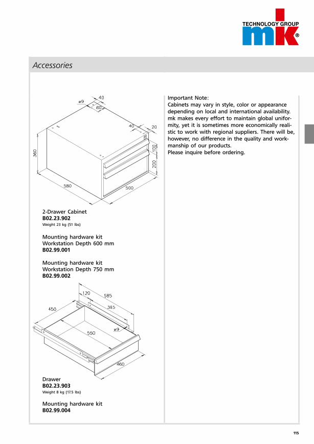
115
Accessories
2-Drawer CabinetB02.23.902Weight 23 kg (51 lbs)
Mounting hardware kit Workstation Depth 600 mmB02.99.001
Mounting hardware kit Workstation Depth 750 mmB02.99.002
DrawerB02.23.903Weight 8 kg (17.5 lbs)
Mounting hardware kit B02.99.004
Important Note:
Cabinets may vary in style, color or appearance
depending on local and international availability.
mk makes every effort to maintain global unifor-
mity, yet it is sometimes more economically reali-
stic to work with regional suppliers. There will be,
however, no difference in the quality and work-
manship of our products.
Please inquire before ordering.
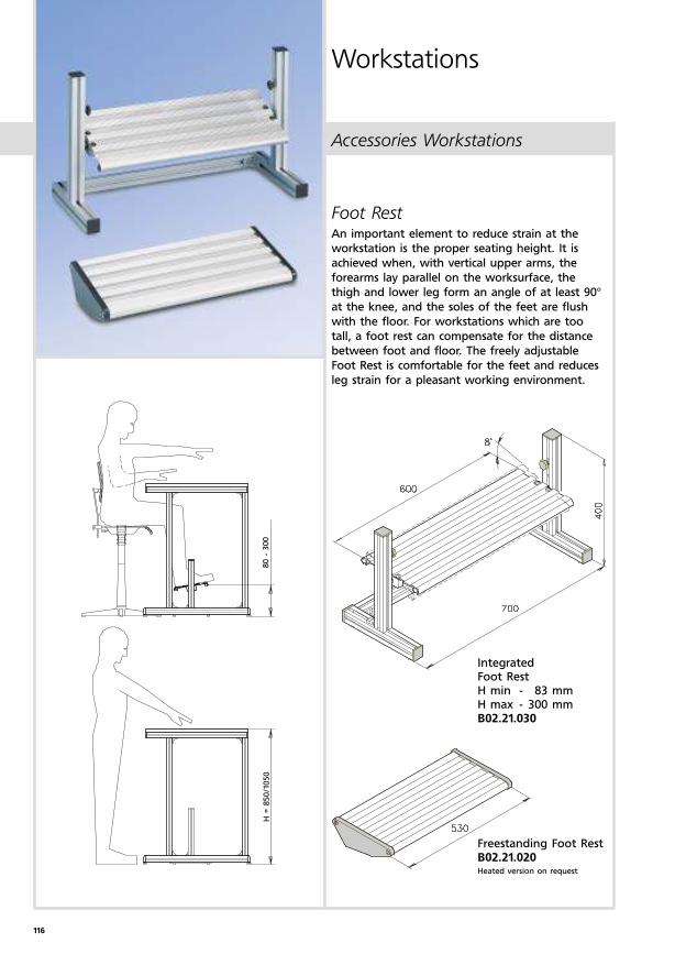
116
H =
850/1
050
80 -
300
Accessories Workstations
Workstations
IntegratedFoot RestH min - 83 mmH max - 300 mmB02.21.030
Freestanding Foot RestB02.21.020Heated version on request
Foot RestAn important element to reduce strain at the
workstation is the proper seating height. It is
achieved when, with vertical upper arms, the
forearms lay parallel on the worksurface, the
thigh and lower leg form an angle of at least 90°
at the knee, and the soles of the feet are flush
with the floor. For workstations which are too
tall, a foot rest can compensate for the distance
between foot and floor. The freely adjustable
Foot Rest is comfortable for the feet and reduces
leg strain for a pleasant working environment.
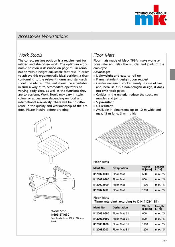
117
Accessories Workstations
Work StoolsThe correct seating position is a requirement for
relaxed and strain-free work. The optimum ergo-
nomic position is described on page 116 in combi-
nation with a height adjustable foot rest. In order
to achieve this ergonomically ideal position, a chair
conforming to the relevant norms and standards
should be utilized. The seat should be adjustable
in such a way as to accomodate operators of
varying body sizes, as well as the functions they
are to perform. Work Stools may vary in style,
colour or appearance depending on local and
international availability. There will be no diffe-
rence in the quality and workmanship of the pro-
duct. Please inquire before ordering.
Work StoolK606-ST1030Seat height from 480 to 880 mm,
black
Floor MatsFloor mats made of black TPE-V make worksta-
tions safer and relax the muscles and joints of the
employee.
Advantages:
Lightweight and easy to roll up
Flame retardant design upon request
Creates minimum smoke density in case of fire
and, because it is a non-halogen design, it does
not emit toxic gases
Cavities in the material reduce the stress on
muscles and joints
Slip-resistant
Oil-resistant
Available in dimensions up to 1.2 m wide and
max. 15 m long, 3 mm thick
Floor Mats
Ident No. DesignationWidthB [mm]
LengthL [m]
K12002.0600 Floor Mat 600 max. 15
K12002.0800 Floor Mat 800 max. 15
K12002.1000 Floor Mat 1000 max. 15
K12002.1200 Floor Mat 1200 max. 15
Ident No. DesignationWidthB [mm]
LengthL [m]
K12003.0600 Floor Mat B1 600 max. 15
K12003.0800 Floor Mat B1 800 max. 15
K12003.1000 Floor Mat B1 1000 max. 15
K12003.1200 Floor Mat B1 1200 max. 15
Floor Mats
(flame retardant according to DIN 4102-1 B1)
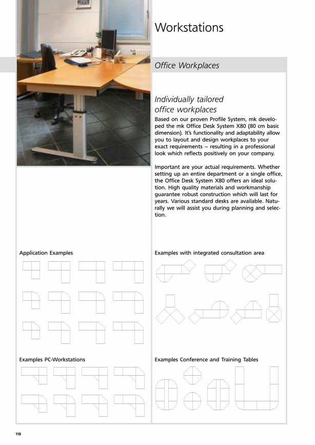
118
Workstations
Individually tailored
office workplacesBased on our proven Profile System, mk develo-
ped the mk Office Desk System X80 (80 cm basic
dimension). It’s functionality and adaptability allow
you to layout and design workplaces to your
exact requirements – resulting in a professional
look which reflects positively on your company.
Important are your actual requirements. Whether
setting up an entire department or a single office,
the Office Desk System X80 offers an ideal solu-
tion. High quality materials and workmanship
guarantee robust construction which will last for
years. Various standard desks are available. Natu-
rally we will assist you during planning and selec-
tion.
Application Examples
Examples PC-Workstations Examples Conference and Training Tables
Examples with integrated consultation area
Office Workplaces
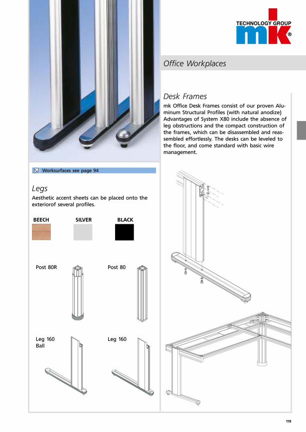
119
Desk Framesmk Office Desk Frames consist of our proven Alu-
minum Structural Profiles (with natural anodize)
Advantages of System X80 include the absence of
leg obstructions and the compact construction of
the frames, which can be disassembled and reas-
sembled effortlessly. The desks can be leveled to
the floor, and come standard with basic wire
management.
LegsAesthetic accent sheets can be placed onto the
exteriorof several profiles.
BEECH SILVER BLACK
Post 80R Post 80
Leg 160
Ball
Leg 160
Worksurfaces see page 94
Office Workplaces

120
Ordering instructions and example
Workstations
Defining Form and Function The workstation must be layed out in such a way
as to satisfy two (principally) important factors.
One the one hand there are economic considera-
tions such as the efficient production, manufac-
ture or assembly of a given product while on the
other maintaining employee health and well-being
while at work.
In order to accomplish this it is necessary to sepa-
rate and distinguish between the required human
and technical aspects in an effort to formulate an
appropriate workstation. The result will be an mk
Workstation which is custom-tailored to the speci-
fic requirements of the customer, while satisfying
both the ergonomic and economic considerations.
Establishing the Requirements for
the Proper WorkstationIt is important to first define the scope of the
acti-vities to be performed at the workstation.
Is the workstation subject to heavy loads or
large forces, or is it designed for light assembly
where precision plays more of a role?
What is the size of the product, it’s dimensions
and weight?
Will there only be one product, or could there
be multiple, different products?
Will the processes performed always be the
same?
Is this a free-standing workstation, or will it be
part of a larger system?
The resulting answers will already point to whe-
ther a light or heavy workstation is appropriate,
and whether the height can be fixed or needs to
be adjustable.
Ergonomic Considerations What type and duration of work can the
employee be expected to perform at the work-
station?
Can work categories be defined?
Must considerations be made for more than
one individual?
How large is the invidivual?
Herewith the actual work considerations for both
the user and the product should be defined.
With respect to the following parameters, define
the type of work to be performed and evaluate
the importance of the required elements.
Type of work performed: Manufacturing,
assembly, rework, testing, packaging, shipping,
etc.
Evaluation: Importance, frequency, sequence,
accessibility, freedom of movement
Required supplies: Production aids, tools,
assembly parts, information presentation, etc.
Workstation requirements: Risers, shelves,
swing arms, lighting, etc. but also work stools,
foot rests, etc.
When planning a workstation, consider that the
best solution to provide a safe and efficient work-
place is often only achieved when understanding
the entire process as a whole. Laying out single
workstations, without the larger picture in mind,
can result in bottlenecks or minimize their full
potential. Therefore, sensible layout planning
must be used, which takes into account and opti-
mises the whole material flow. We will be pleased
to assist you with the planning.
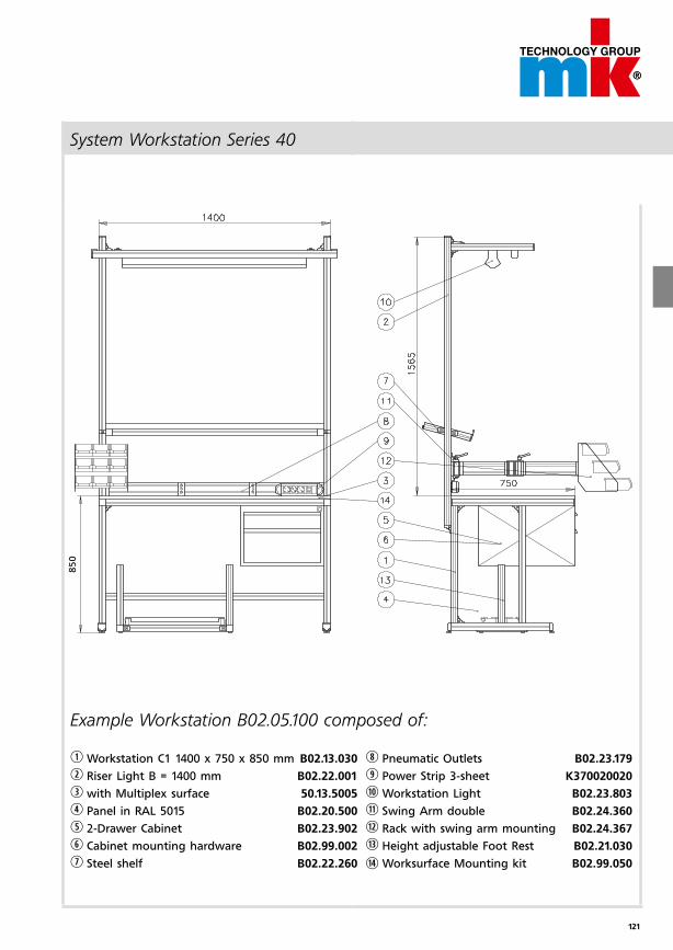
121
850
System Workstation Series 40
Example Workstation B02.05.100 composed of:
q Workstation C1 1400 x 750 x 850 mm B02.13.030
w Riser Light B = 1400 mm B02.22.001
e with Multiplex surface 50.13.5005
r Panel in RAL 5015 B02.20.500
t 2-Drawer Cabinet B02.23.902
y Cabinet mounting hardware B02.99.002
u Steel shelf B02.22.260
i Pneumatic Outlets B02.23.179
o Power Strip 3-sheet K370020020
a Workstation Light B02.23.803
s Swing Arm double B02.24.360
d Rack with swing arm mounting B02.24.367
f Height adjustable Foot Rest B02.21.030
g Worksurface Mounting kit B02.99.050
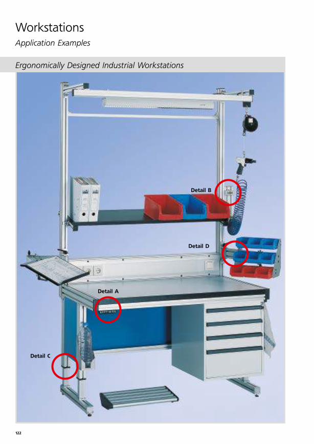
122
WorkstationsApplication Examples
Detail C
Detail B
Detail D
Detail A
Ergonomically Designed Industrial Workstations
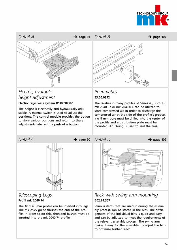
123
Detail D è page 109Detail C è page 90
Detail A è page 93
Rack with swing arm mounting B02.24.367
Various items that are used in during the assem-
bly process, can be stored in the bins. The arran-
gement of the individual bins is quick and easy
and can be adjusted to meet the requirements of
the relevant assembly process. The swing arm
makes it easy for the assembler to adjust the bins
to optimize his/her reach.
Telescoping Legs Profil mk 2040.74
The 40 x 40 mm profile can be inserted into legs.
The mk 2575 guide finishes the end of the pro-
file. In order to do this, threaded bushes must be
inserted into the mk 2040.74 profile.
Pneumatics 53.00.0352
The cavities in many profiles of Series 40, such as
mk 2040.02 or mk 2040.03, can be utilized to
store compressed air. In order to discharge the
compressed air at the side of the profile's groove,
a ø 8 mm bore must be drilled into the center of
the profile and a distribution plate must be
mounted. An O-ring is used to seal the area.
Electric, hydraulic
height adjustment Electric Ergoswiss system K110090002
The height is electrically and hydraulically adju-
stable. A manual switch is used to adjust the
positions. The control module provides the option
to store various positions and return to these
adjustments later with a push of a button.
Detail B è page 102
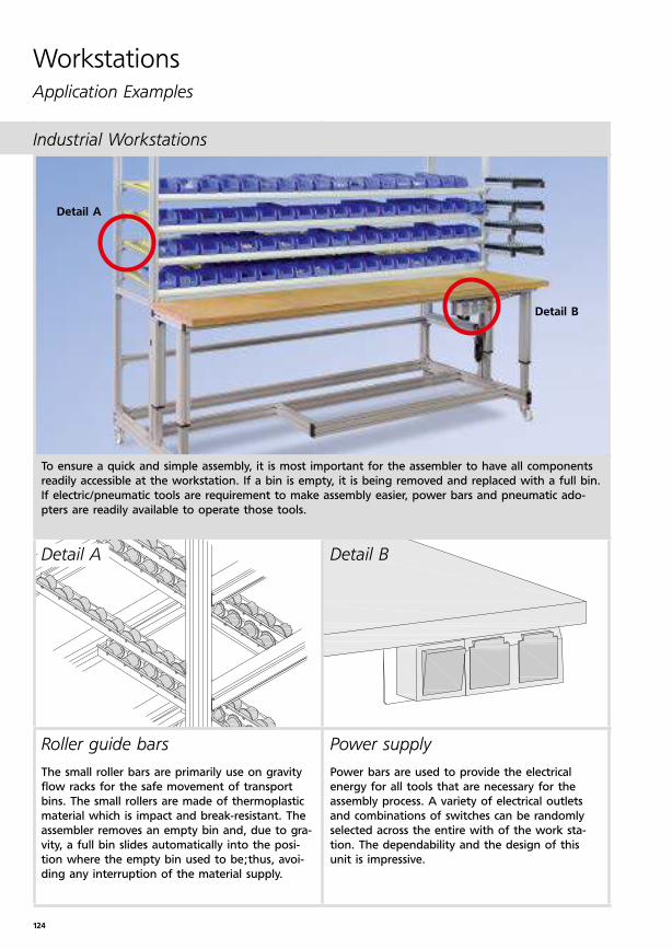
124
WorkstationsApplication Examples
Industrial Workstations
Detail A
Detail B
To ensure a quick and simple assembly, it is most important for the assembler to have all components
readily accessible at the workstation. If a bin is empty, it is being removed and replaced with a full bin.
If electric/pneumatic tools are requirement to make assembly easier, power bars and pneumatic ado-
pters are readily available to operate those tools.
Power supply
Power bars are used to provide the electrical
energy for all tools that are necessary for the
assembly process. A variety of electrical outlets
and combinations of switches can be randomly
selected across the entire with of the work sta-
tion. The dependability and the design of this
unit is impressive.
Roller guide bars
The small roller bars are primarily use on gravity
flow racks for the safe movement of transport
bins. The small rollers are made of thermoplastic
material which is impact and break-resistant. The
assembler removes an empty bin and, due to gra-
vity, a full bin slides automatically into the posi-
tion where the empty bin used to be;thus, avoi-
ding any interruption of the material supply.
Detail BDetail A
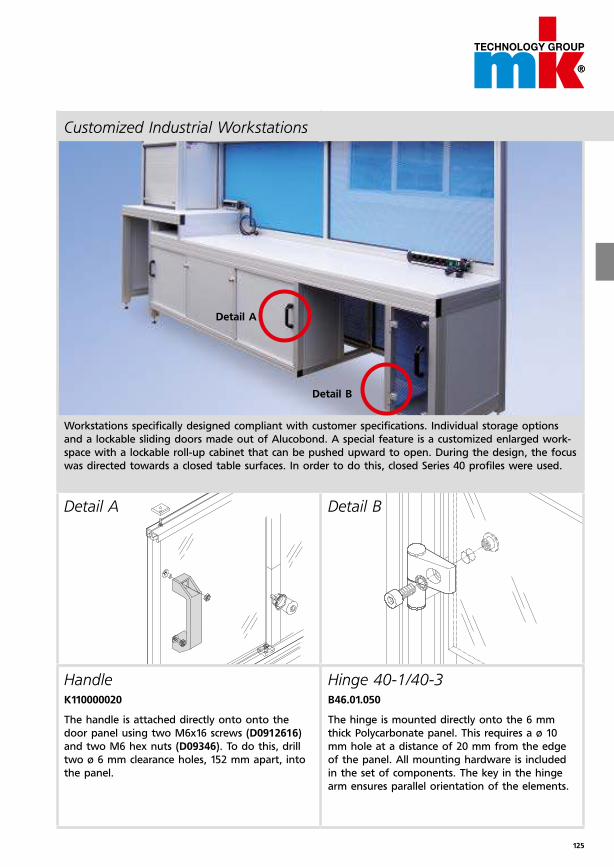
125
Customized Industrial Workstations
Detail A
Detail B
Workstations specifically designed compliant with customer specifications. Individual storage options
and a lockable sliding doors made out of Alucobond. A special feature is a customized enlarged work-
space with a lockable roll-up cabinet that can be pushed upward to open. During the design, the focus
was directed towards a closed table surfaces. In order to do this, closed Series 40 profiles were used.
Hinge 40-1/40-3 B46.01.050
The hinge is mounted directly onto the 6 mm
thick Polycarbonate panel. This requires a ø 10
mm hole at a distance of 20 mm from the edge
of the panel. All mounting hardware is included
in the set of components. The key in the hinge
arm ensures parallel orientation of the elements.
HandleK110000020
The handle is attached directly onto onto the
door panel using two M6x16 screws (D0912616)
and two M6 hex nuts (D09346). To do this, drill
two ø 6 mm clearance holes, 152 mm apart, into
the panel.
Detail A Detail B
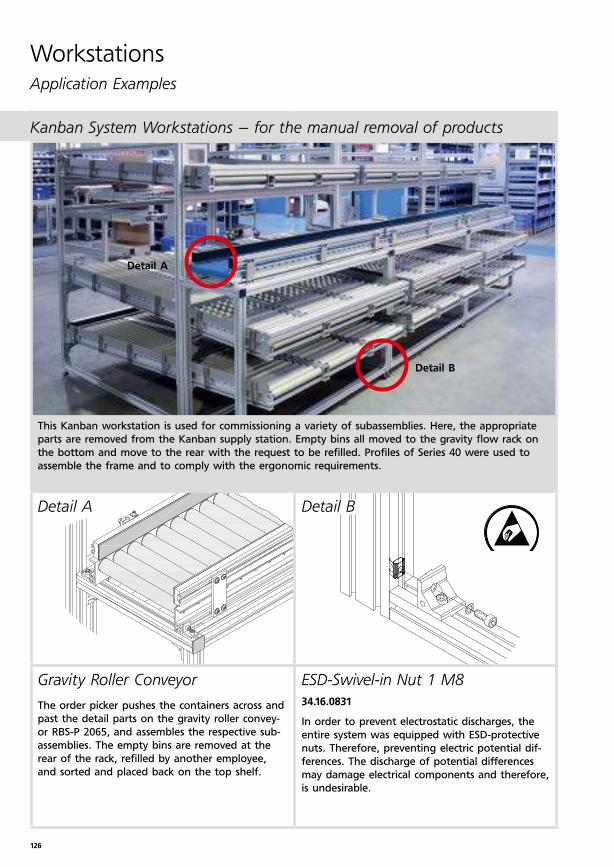
126
WorkstationsApplication Examples
Kanban System Workstations – for the manual removal of products
This Kanban workstation is used for commissioning a variety of subassemblies. Here, the appropriate
parts are removed from the Kanban supply station. Empty bins all moved to the gravity flow rack on
the bottom and move to the rear with the request to be refilled. Profiles of Series 40 were used to
assemble the frame and to comply with the ergonomic requirements.
Detail BDetail A
ESD-Swivel-in Nut 1 M8
34.16.0831
In order to prevent electrostatic discharges, the
entire system was equipped with ESD-protective
nuts. Therefore, preventing electric potential dif-
ferences. The discharge of potential differences
may damage electrical components and therefore,
is undesirable.
Gravity Roller Conveyor
The order picker pushes the containers across and
past the detail parts on the gravity roller convey-
or RBS-P 2065, and assembles the respective sub-
assemblies. The empty bins are removed at the
rear of the rack, refilled by another employee,
and sorted and placed back on the top shelf.
Detail A
Detail B
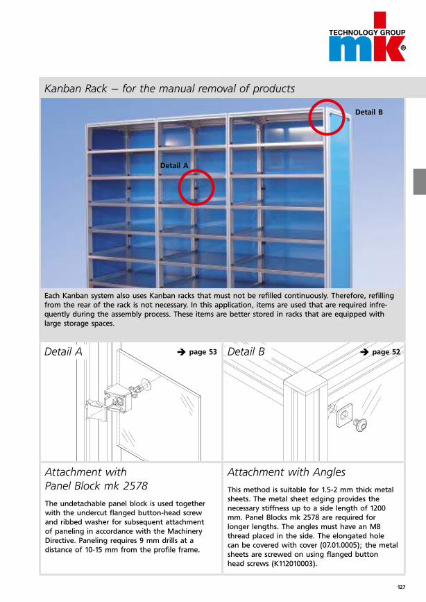
127
Each Kanban system also uses Kanban racks that must not be refilled continuously. Therefore, refilling
from the rear of the rack is not necessary. In this application, items are used that are required infre-
quently during the assembly process. These items are better stored in racks that are equipped with
large storage spaces.
Detail B è page 52Detail A è page 53
Attachment with Angles
This method is suitable for 1.5-2 mm thick metal
sheets. The metal sheet edging provides the
necessary stiffness up to a side length of 1200
mm. Panel Blocks mk 2578 are required for
longer lengths. The angles must have an M8
thread placed in the side. The elongated hole
can be covered with cover (07.01.0005); the metal
sheets are screwed on using flanged button
head screws (K112010003).
Attachment with
Panel Block mk 2578
The undetachable panel block is used together
with the undercut flanged button-head screw
and ribbed washer for subsequent attachment
of paneling in accordance with the Machinery
Directive. Paneling requires 9 mm drills at a
distance of 10-15 mm from the profile frame.
Detail A
Detail B
Kanban Rack – for the manual removal of products
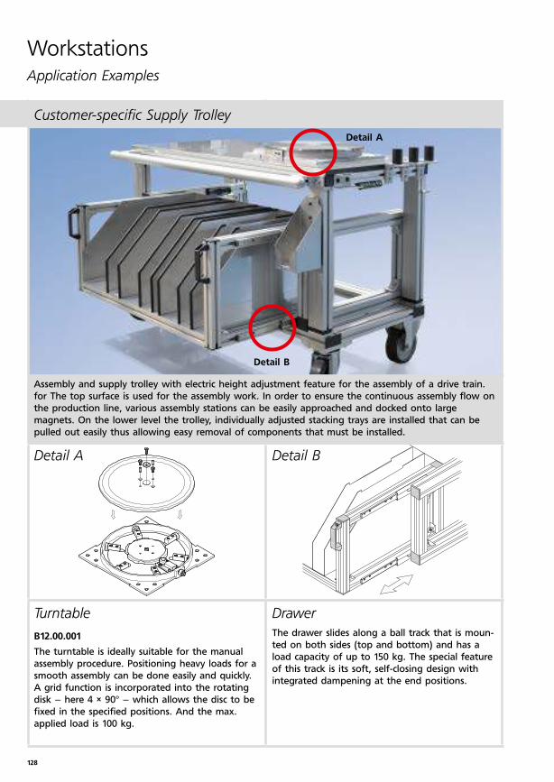
128
WorkstationsApplication Examples
Customer-specific Supply Trolley
Assembly and supply trolley with electric height adjustment feature for the assembly of a drive train.
for The top surface is used for the assembly work. In order to ensure the continuous assembly flow on
the production line, various assembly stations can be easily approached and docked onto large
magnets. On the lower level the trolley, individually adjusted stacking trays are installed that can be
pulled out easily thus allowing easy removal of components that must be installed.
Detail BDetail A
Drawer
The drawer slides along a ball track that is moun-
ted on both sides (top and bottom) and has a
load capacity of up to 150 kg. The special feature
of this track is its soft, self-closing design with
integrated dampening at the end positions.
Turntable
B12.00.001 The turntable is ideally suitable for the manual
assembly procedure. Positioning heavy loads for a
smooth assembly can be done easily and quickly.
A grid function is incorporated into the rotating
disk – here 4 × 90° – which allows the disc to be
fixed in the specified positions. And the max.
applied load is 100 kg.
Detail A
Detail B
129
Notes
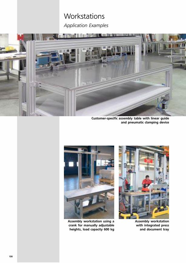
130
WorkstationsApplication Examples
Customer-specific assembly table with linear guide
and pneumatic clamping device
Assembly workstation using a
crank for manually adjustable
heights, load capacity 600 kg
Assembly workstation
with integrated press
and document tray
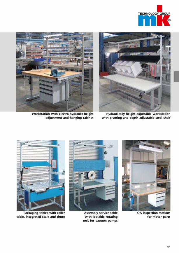
131
Workstation with electro-hydraulic height
adjustment and hanging cabinet
Hydraulically height adjustable workstation
with pivoting and depth adjustable steel shelf
Packaging tables with roller
table, integrated scale and chute
Assembly service table
with lockable rotating
unit for vacuum pumps
QA inspection stations
for motor parts
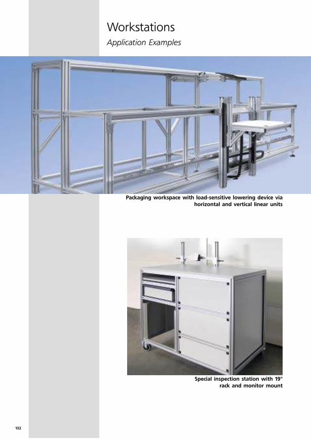
132
WorkstationsApplication Examples
Packaging workspace with load-sensitive lowering device via
horizontal and vertical linear units
Special inspection station with 19"
rack and monitor mount
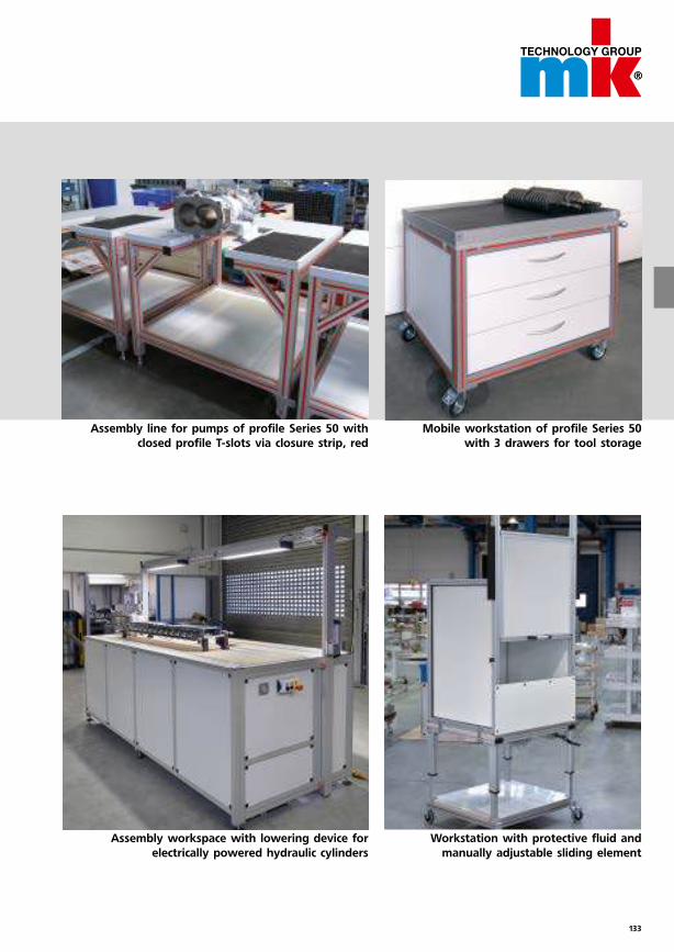
133
Mobile workstation of profile Series 50
with 3 drawers for tool storage
Assembly line for pumps of profile Series 50 with
closed profile T-slots via closure strip, red
Assembly workspace with lowering device for
electrically powered hydraulic cylinders
Workstation with protective fluid and
manually adjustable sliding element
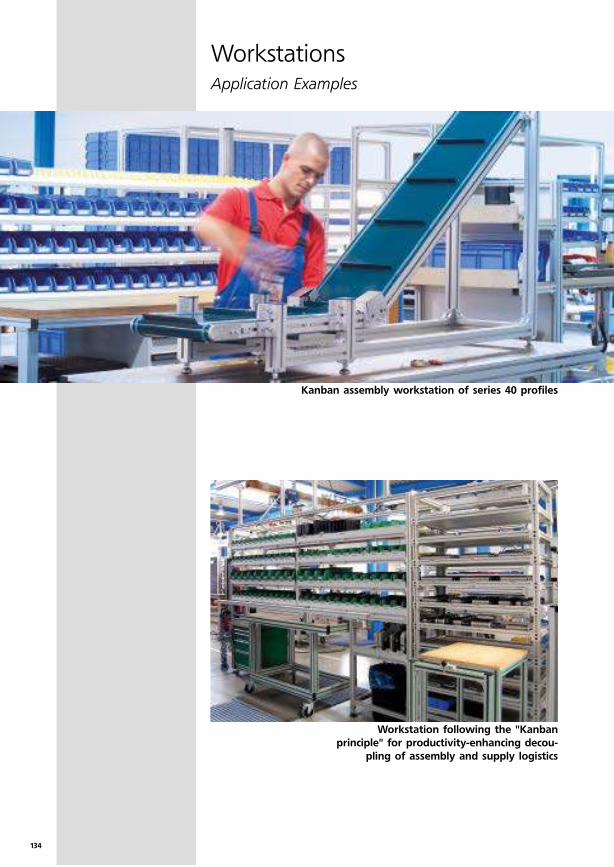
134
WorkstationsApplication Examples
Kanban assembly workstation of series 40 profiles
Workstation following the "Kanban
principle" for productivity-enhancing decou-
pling of assembly and supply logistics
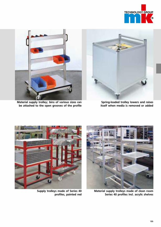
135
Spring-loaded trolley lowers and raises
itself when media is removed or added
Material supply trolley; bins of various sizes can
be attached to the open grooves of the profile
Supply trolleys made of Series 40
profiles, painted red
Material supply trolleys made of clean room
Series 40 profiles incl. acrylic shelves
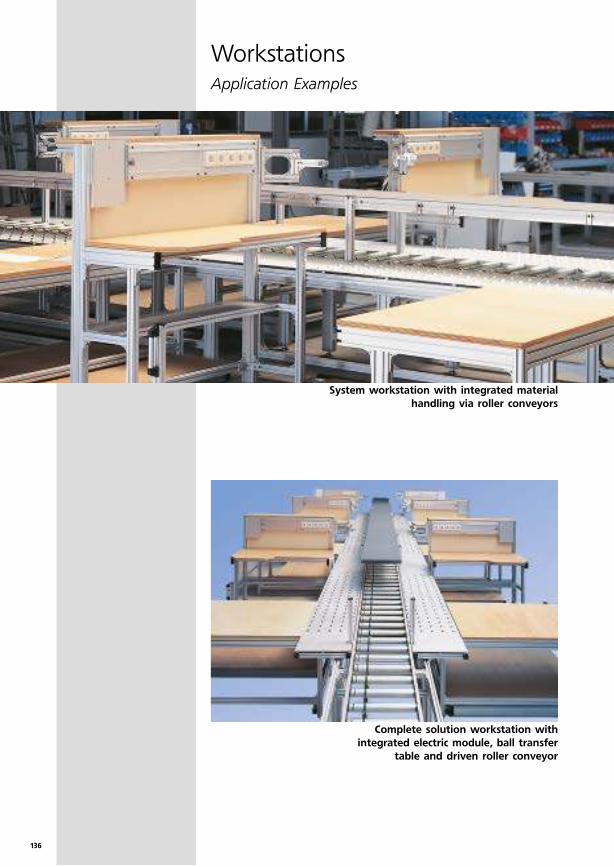
136
WorkstationsApplication Examples
Complete solution workstation with
integrated electric module, ball transfer
table and driven roller conveyor
System workstation with integrated material
handling via roller conveyors
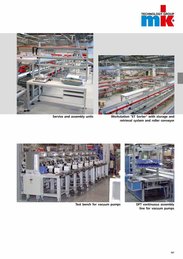
137
DFT continuous assembly
line for vacuum pumps
Test bench for vacuum pumps
Service and assembly units Workstation "ET Sorter" with storage and
retrieval system and roller conveyor
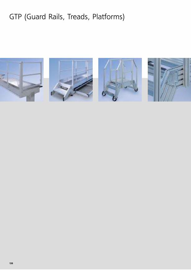
138
GTP (Guard Rails, Treads, Platforms)
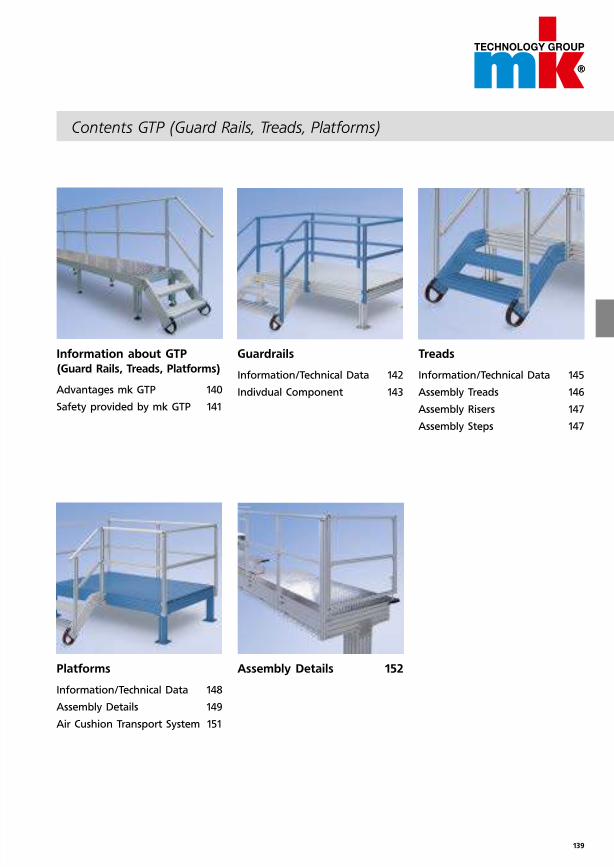
139
Contents GTP (Guard Rails, Treads, Platforms)
Information about GTP
(Guard Rails, Treads, Platforms)
Advantages mk GTP 140
Safety provided by mk GTP 141
Platforms
Information/Technical Data 148
Assembly Details 149
Air Cushion Transport System 151
Guardrails
Information/Technical Data 142
Indivdual Component 143
Assembly Details 152
Treads
Information/Technical Data 145
Assembly Treads 146
Assembly Risers 147
Assembly Steps 147
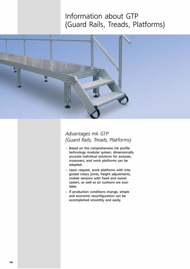
140
Advantages mk GTP
(Guard Rails, Treads, Platforms)
Information about GTP (Guard Rails, Treads, Platforms)
Based on the comprehensive mk profile
technology modular system, dimensionally
accurate individual solutions for accesses,
crossovers, and work platforms can be
adapted.
Upon request, work platforms with inte-
grated rotary joints, height adjustments,
mobile versions with fixed and swivel
casters, as well as air cushions are avai-
lable.
If production conditions change, simple
and economic reconfiguration can be
accomplished smoothly and easily.
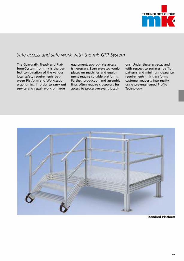
141
Safe access and safe work with the mk GTP System
The Guardrail-, Tread- and Plat-
form-System from mk is the per-
fect combination of the various
local safety requirements bet-
ween Platform and Workstation
ergonomics. In order to carry out
service and repair work on large
equipment, appropriate access
is necessary. Even elevated work-
places on machines and equip-
ment require suitable platforms.
Further, production and assembly
lines often require crossovers for
access to process-relevant locati-
ons. Under these aspects, and
with respect to surfaces, traffic
patterns and minimum clearance
requirements, mk transforms
customer requests into reality
using pre-engineered Profile
Technology.
Standard Platform
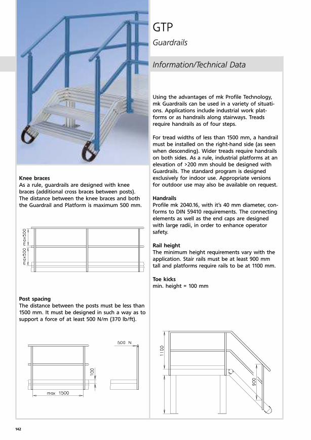
142
Using the advantages of mk Profile Technology,
mk Guardrails can be used in a variety of situati-
ons. Applications include industrial work plat-
forms or as handrails along stairways. Treads
require handrails as of four steps.
For tread widths of less than 1500 mm, a handrail
must be installed on the right-hand side (as seen
when descending). Wider treads require handrails
on both sides. As a rule, industrial platforms at an
elevation of >200 mm should be designed with
Guardrails. The standard program is designed
exclusively for indoor use. Appropriate versions
for outdoor use may also be available on request.
Handrails
Profile mk 2040.16, with it’s 40 mm diameter, con-
forms to DIN 59410 requirements. The connecting
elements as well as the end caps are designed
with large radii, in order to enhance operator
safety.
Rail height
The minimum height requirements vary with the
application. Stair rails must be at least 900 mm
tall and platforms require rails to be at 1100 mm.
Toe kicks
min. height = 100 mm
Knee braces
As a rule, guardrails are designed with knee
braces (additional cross braces between posts).
The distance between the knee braces and both
the Guardrail and Platform is maximum 500 mm.
Post spacing
The distance between the posts must be less than
1500 mm. It must be designed in such a way as to
support a force of at least 500 N/m (370 lb/ft).
Information/Technical Data
GTPGuardrails
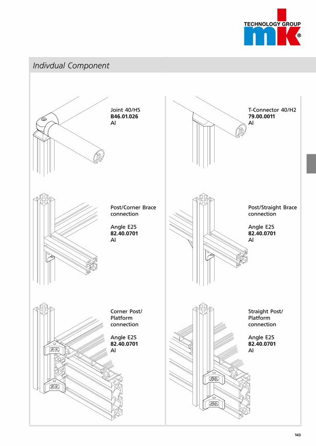
143
Joint 40/H5B46.01.026Al
Post/Corner Brace connection
Angle E2582.40.0701Al
Corner Post/ Platform connection
Angle E2582.40.0701Al
T-Connector 40/H279.00.0011Al
Post/Straight Brace connection
Angle E2582.40.0701Al
Straight Post/ Platform connection
Angle E2582.40.0701Al
Indivdual Component
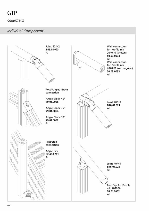
144
Indivdual Component
GTPGuardrails
Wall connectionfor Profile mk 2040.16 (shown)
50.03.0034AlWall connection for Profile mk 2040.01 (rectangular)
50.03.0033Al
Joint 40/H3B46.01.024Al
Joint 40/H4B46.01.025Al
End Cap for Profile mk 2040.1676.01.0002Al
Joint 40/H2B46.01.023Al
Post/Angled Brace connection
Angle Block 45°79.01.0066
Angle Block 35°79.01.0064
Angle Block 30°79.01.0062Al
Post/Stair connection
Angle E2582.40.0701Al
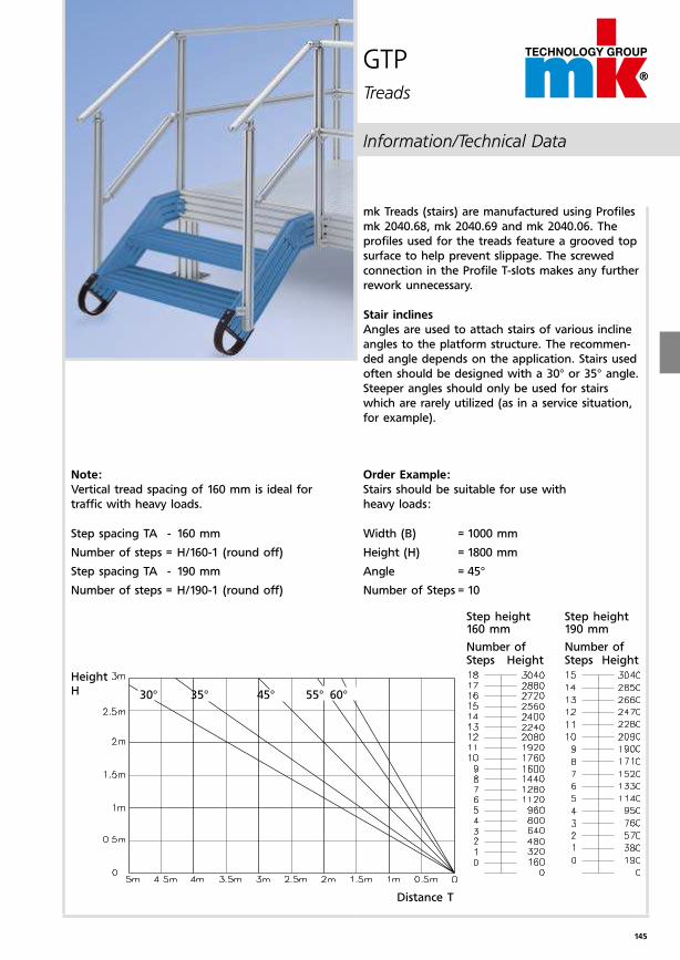
145
30° 35° 45° 55° 60°
Order Example:
Stairs should be suitable for use with
heavy loads:
Width (B) = 1000 mm
Height (H) = 1800 mm
Angle = 45°
Number of Steps = 10
Note:
Vertical tread spacing of 160 mm is ideal for
traffic with heavy loads.
Step spacing TA - 160 mm
Number of steps = H/160-1 (round off)
Step spacing TA - 190 mm
Number of steps = H/190-1 (round off)
mk Treads (stairs) are manufactured using Profiles
mk 2040.68, mk 2040.69 and mk 2040.06. The
profiles used for the treads feature a grooved top
surface to help prevent slippage. The screwed
connection in the Profile T-slots makes any further
rework unnecessary.
Stair inclines
Angles are used to attach stairs of various incline
angles to the platform structure. The recommen-
ded angle depends on the application. Stairs used
often should be designed with a 30° or 35° angle.
Steeper angles should only be used for stairs
which are rarely utilized (as in a service situation,
for example).
Height H
Distance T
Number of Steps Height
Number of Steps Height
Step height160 mm
Step height190 mm
GTPTreads
Information/Technical Data
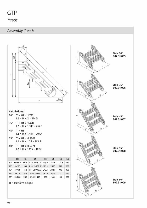
146
TA
Assembly Treads
Stair 30°B02.31.005
Stair 35°B02.31.006
Stair 45°B02.31.007
Stair 55°B02.31.008
Stair 60°B02.31.009
Calculations:
30° T = H1 x 1.732 L2 = H x 2 - 314.5
35° T = H1 x 1.428 L2 = H x 1.743 - 267.5
45° T = H1 L2 = H x 1.414 - 204.4
55° T = H1 x 0.7002 L2 = H x 1.22 - 163.5
60° T = H1 x 0.5774 L2 = H x 1.155 - 147.7
H = Platform height
GTPTreads
H1 H2 L1 L3 L4 L5 L6
30° H+86.6 86.6 L1=L2+487.5 173.2 314.5 224.5 150
35° H+105 105 L1=L2+450.5 183.1 267.5 177 150
45° H+150 150 L1=L2+416.5 212.1 204.5 113 150
55° H+214 214 L1=L2+425 261.5 163.5 71 150
60° H+260 260 L1=L2+448 300 148 55 150
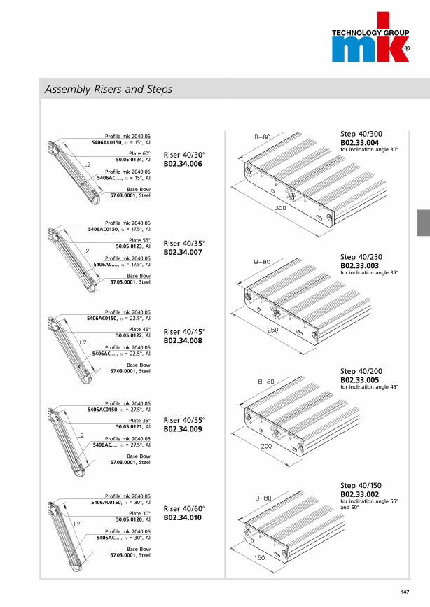
147
Profile mk 2040.06 5406AC0150, α = 15°, Al
Plate 60° 50.05.0124, Al
Profile mk 2040.06 5406AC...., α = 15°, Al
Base Bow 67.03.0001, Steel
Profile mk 2040.06 5406AC0150, α = 27.5°, Al
Plate 35° 50.05.0121, Al
Profile mk 2040.06 5406AC...., α = 27.5°, Al
Base Bow 67.03.0001, Steel
Profile mk 2040.06 5406AC0150, α = 30°, Al
Plate 30° 50.05.0120, Al
Profile mk 2040.06 5406AC...., α = 30°, Al
Base Bow 67.03.0001, Steel
Step 40/300B02.33.004for inclination angle 30°
Step 40/250B02.33.003for inclination angle 35°
Step 40/200B02.33.005for inclination angle 45°
Step 40/150B02.33.002for inclination angle 55° and 60°
Riser 40/30°B02.34.006
Riser 40/35°B02.34.007
Riser 40/45°B02.34.008
Riser 40/55°B02.34.009
Riser 40/60°B02.34.010
Profile mk 2040.06 5406AC0150, α = 17.5°, Al
Plate 55° 50.05.0123, Al
Profile mk 2040.06 5406AC...., α = 17.5°, Al
Base Bow 67.03.0001, Steel
Profile mk 2040.06 5406AC0150, α = 22.5°, Al
Plate 45° 50.05.0122, Al
Profile mk 2040.06 5406AC...., α = 22.5°, Al
Base Bow 67.03.0001, Steel
Assembly Risers and Steps
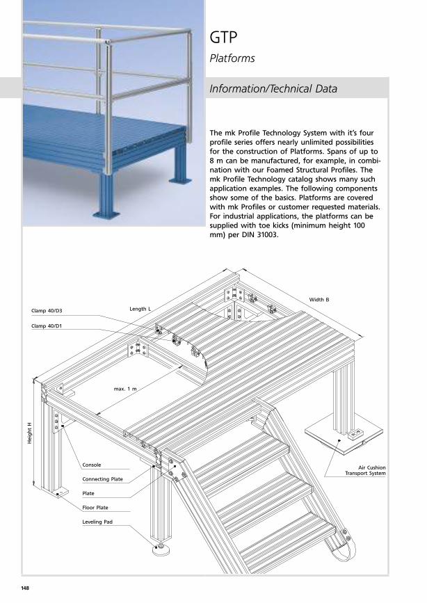
148
The mk Profile Technology System with it’s four
profile series offers nearly unlimited possibilities
for the construction of Platforms. Spans of up to
8 m can be manufactured, for example, in combi-
nation with our Foamed Structural Profiles. The
mk Profile Technology catalog shows many such
application examples. The following components
show some of the basics. Platforms are covered
with mk Profiles or customer requested materials.
For industrial applications, the platforms can be
supplied with toe kicks (minimum height 100
mm) per DIN 31003.
Clamp 40/D3
Clamp 40/D1
Length L
max. 1 m
Console
Connecting Plate
Plate
Floor Plate
Leveling Pad
Heig
ht
H
Width B
GTPPlatforms
Air Cushion Transport System
Information/Technical Data
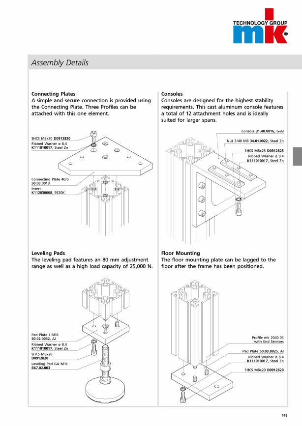
149
Assembly Details
Connecting Plates
A simple and secure connection is provided using
the Connecting Plate. Three Profiles can be
attached with this one element.
SHCS M8x20 D0912820
Ribbed Washer ø 8.4 K111010017, Steel Zn
Connecting Plate 40/5 50.03.0013
Insert K112030008, 9S20K
Console 31.40.0016, G-Al
Nut 3/40 M8 34.01.0022, Steel Zn
SHCS M8x25 D0912825
Ribbed Washer ø 8.4
K111010017, Steel Zn
Profile mk 2040.03 with End Services
Pad Plate 50.03.0025, Al
Ribbed Washer ø 8.4 K111010017, Steel Zn
SHCS M8x20 D0912820
Pad Plate J M16 50.02.0032, Al
Ribbed Washer ø 8.4 K111010017, Steel Zn
SHCS M8x20 D0912820
Leveling Pad GA M16 B67.02.003
Consoles
Consoles are designed for the highest stability
requirements. This cast aluminum console features
a total of 12 attachment holes and is ideally
suited for larger spans.
Leveling Pads
The leveling pad features an 80 mm adjustment
range as well as a high load capacity of 25,000 N.
Floor Mounting
The floor mounting plate can be lagged to the
floor after the frame has been positioned.
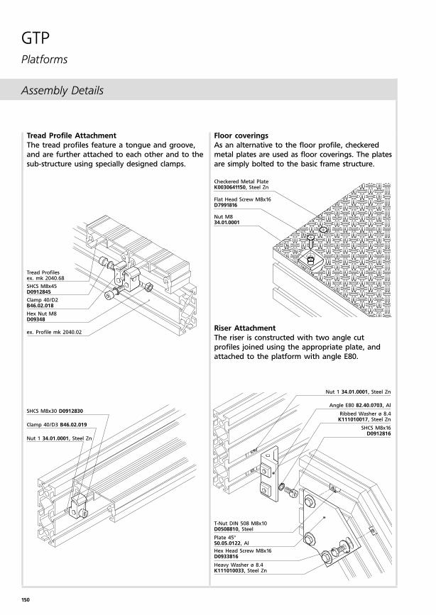
150
Assembly Details
Tread Profiles ex. mk 2040.68
SHCS M8x45 D0912845
Clamp 40/D2 B46.02.018
Hex Nut M8 D09348
ex. Profile mk 2040.02
Nut 1 34.01.0001, Steel Zn
Angle E80 82.40.0703, Al
Ribbed Washer ø 8.4K111010017, Steel Zn
SHCS M8x16D0912816
T-Nut DIN 508 M8x10D0508810, Steel
Plate 45°50.05.0122, Al
Hex Head Screw M8x16D0933816
Heavy Washer ø 8.4K111010033, Steel Zn
SHCS M8x30 D0912830
Clamp 40/D3 B46.02.019
Nut 1 34.01.0001, Steel Zn
Tread Profile Attachment
The tread profiles feature a tongue and groove,
and are further attached to each other and to the
sub-structure using specially designed clamps.
Riser Attachment
The riser is constructed with two angle cut
profiles joined using the appropriate plate, and
attached to the platform with angle E80.
GTPPlatforms
Checkered Metal Plate K0030641150, Steel Zn
Flat Head Screw M8x16 D7991816
Nut M8 34.01.0001
Floor coverings
As an alternative to the floor profile, checkered
metal plates are used as floor coverings. The plates
are simply bolted to the basic frame structure.
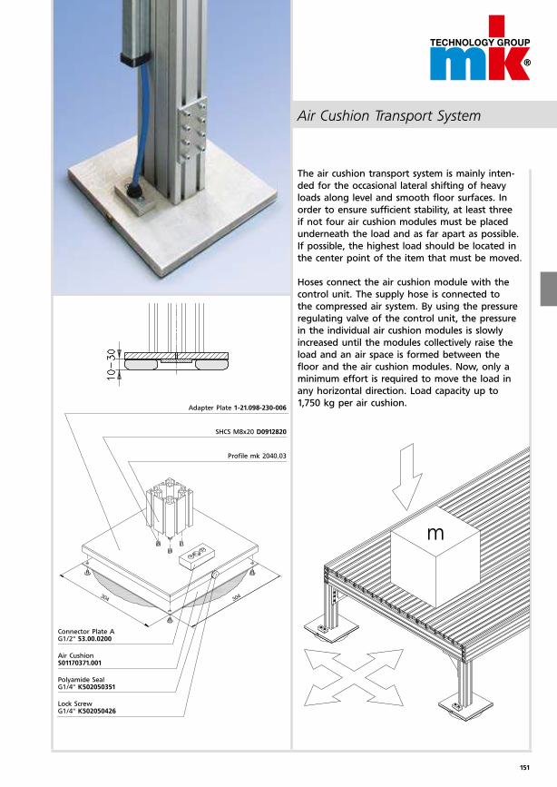
151
m
Air Cushion Transport System
Adapter Plate 1-21.098-230-006
SHCS M8x20 D0912820
Profile mk 2040.03
Connector Plate A G1/2" 53.00.0200
Air Cushion S01170371.001
Polyamide Seal G1/4" K502050351
Lock Screw G1/4" K502050426
The air cushion transport system is mainly inten-
ded for the occasional lateral shifting of heavy
loads along level and smooth floor surfaces. In
order to ensure sufficient stability, at least three
if not four air cushion modules must be placed
underneath the load and as far apart as possible.
If possible, the highest load should be located in
the center point of the item that must be moved.
Hoses connect the air cushion module with the
control unit. The supply hose is connected to
the compressed air system. By using the pressure
regulating valve of the control unit, the pressure
in the individual air cushion modules is slowly
increased until the modules collectively raise the
load and an air space is formed between the
floor and the air cushion modules. Now, only a
minimum effort is required to move the load in
any horizontal direction. Load capacity up to
1,750 kg per air cushion.
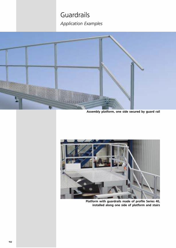
152
GuardrailsApplication Examples
Assembly platform, one side secured by guard rail
Platform with guardrails made of profile Series 40,
installed along one side of platform and stairs
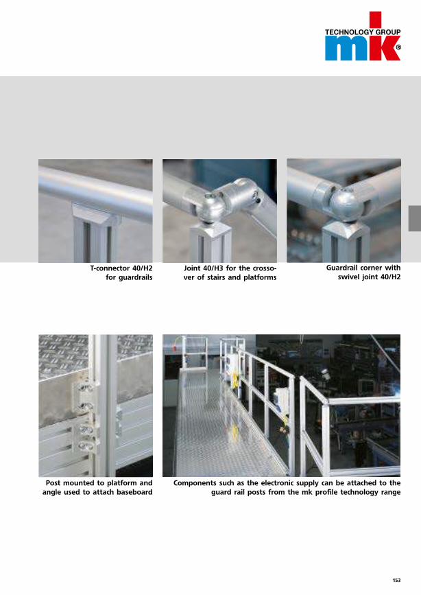
153
Guardrail corner with
swivel joint 40/H2
Components such as the electronic supply can be attached to the
guard rail posts from the mk profile technology range
T-connector 40/H2
for guardrails
Post mounted to platform and
angle used to attach baseboard
Joint 40/H3 for the crosso-
ver of stairs and platforms
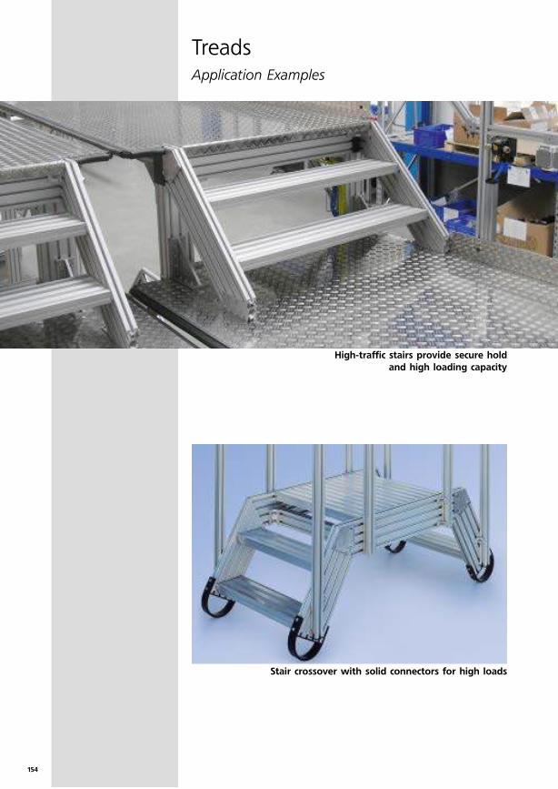
154
TreadsApplication Examples
High-traffic stairs provide secure hold
and high loading capacity
Stair crossover with solid connectors for high loads
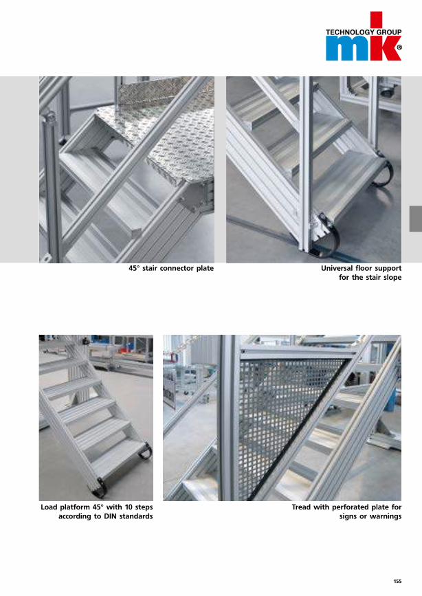
155
Universal floor support
for the stair slope
Tread with perforated plate for
signs or warnings
Load platform 45° with 10 steps
according to DIN standards
45° stair connector plate
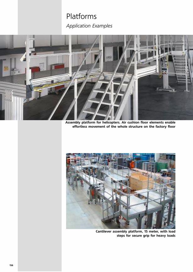
156
Assembly platform for helicopters. Air cushion floor elements enable
effortless movement of the whole structure on the factory floor
PlatformsApplication Examples
Cantilever assembly platform, 15 meter, with load
steps for secure grip for heavy loads
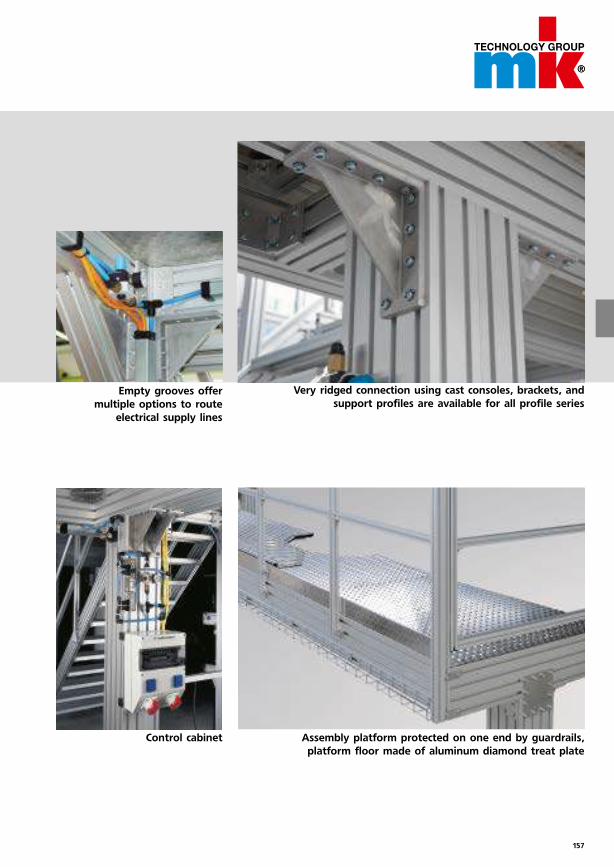
157
Very ridged connection using cast consoles, brackets, and
support profiles are available for all profile series
Assembly platform protected on one end by guardrails,
platform floor made of aluminum diamond treat plate
Control cabinet
Empty grooves offer
multiple options to route
electrical supply lines
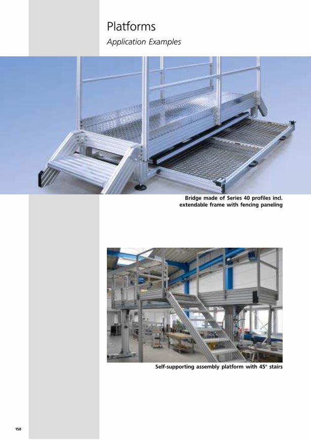
158
PlatformsApplication Examples
Self-supporting assembly platform with 45° stairs
Bridge made of Series 40 profiles incl.
extendable frame with fencing paneling
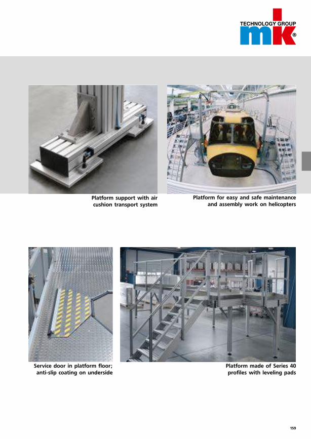
159
Platform for easy and safe maintenance
and assembly work on helicopters
Platform made of Series 40
profiles with leveling pads
Service door in platform floor;
anti-slip coating on underside
Platform support with air
cushion transport system

160
Our service
Range of performance
Reduce your planning time by using the “mk Parts”
CAD parts library!
Online at www.mk-group.com
Free access to CAD data
Simple processing with native and neutral CAD formats
Automatic part list information for the components
Part configuration online
Quick and easy design of your guarding!
To download, click on www.mk-group.com/Service
Conveniently create guarding without costly design
Cost optimization through automatic selection of default fields
Exporting of 3D drawings for further processing or enhance-ment in your CAD system
Immediately obtain your matching mk conveyor or linear
technology system online based on your requirements!
Online selection tool for determining the optimal system based on the parameters entered
Comparison of up to 3 systems at a glance
Motor selection program
Direct link to our e-catalog
mk QuickDesigner Guarding
mk Comparison- and Selection Tool: Conveyor Technology and Linear Motion
mk Parts

161
Order profiles, connectors and accessory elements at
mk-group.com/shop – 24 hours a day!*
Visual parts selection prevents confusion
Search function by name or ID number
Direct price calculation
Order online
Check the status of your order at any time – online!
As a registered user, you can view the history of your orders at
mk in our online shop. Follow the status of your online or off-line
orders. Find out, for example, whether your order is currently in
assembly or whether it has already been shipped.
We deliver your GUF-P MINI and GUF-P 2000 fast!
Top adherence to delivery dates and availability thanks to optimized storage and a lean manufacturing process
We cover a wide range of applications due to standardization and modularization of these units
Fast delivery of spare parts
Price advantage
mk Online Order Tracking
mk Quick Delivery Program (QDP)
mk Profile Technology Online Shop
Be fa
ster!
*Only for commercial customers of the German market

162
Copyright © 2008 Maschinenbau Kitz GmbH, all rights and technical
modifications reserved. Reproduction, in whole or in part, only with
the expressed, written consent of Maschinenbau Kitz GmbH. Legal
venue is Siegburg, Germany. Current as of 7.2013. Issue 3.0.
Our service
We’re there where you need us
work of production, sales and
service sites make it possible to
quickly respond to your require-
ments and make the service you
are used to possible. Our site
addresses are available on our
website at www.mk-group.com.
Every hour of downtime for you
or one of your customers costs
you money and reputation.
Therefore, we are on your side in
the planning and design phase,
as well in after-sales business as
a partner. Our international net-
Headquarters, Troisdorf,
Germany
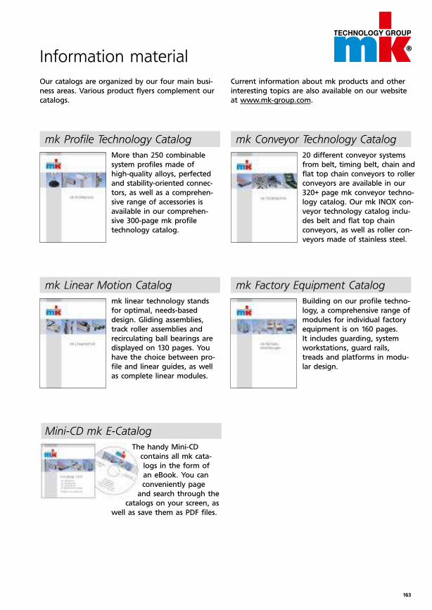
163
Information material
More than 250 combinable
system profiles made of
high-quality alloys, perfected
and stability-oriented connec-
tors, as well as a comprehen-
sive range of accessories is
available in our comprehen-
sive 300-page mk profile
technology catalog.
mk linear technology stands
for optimal, needs-based
de sign. Gliding assemblies,
track roller assemblies and
recirculating ball bearings are
displayed on 130 pages. You
have the choice between pro-
file and linear guides, as well
as complete linear modules.
mk Linear Motion Catalog
20 different conveyor systems
from belt, timing belt, chain and
flat top chain conveyors to roller
conveyors are available in our
320+ page mk conveyor techno-
logy catalog. Our mk INOX con-
veyor technology catalog inclu-
des belt and flat top chain
conveyors, as well as roller con-
veyors made of stainless steel.
mk Conveyor Technology Catalogmk Profile Technology Catalog
Mini-CD mk E-Catalog
Building on our profile techno-
logy, a comprehensive range of
modules for individual factory
equipment is on 160 pages.
It includes guarding, system
workstations, guard rails,
treads and platforms in modu-
lar design.
mk Factory Equipment Catalog
Current information about mk products and other
interesting topics are also available on our website
at www.mk-group.com.
Our catalogs are organized by our four main busi-
ness areas. Various product flyers complement our
catalogs.
The handy Mini-CD
contains all mk cata-
logs in the form of
an eBook. You can
conveniently page
and search through the
catalogs on your screen, as
well as save them as PDF files.
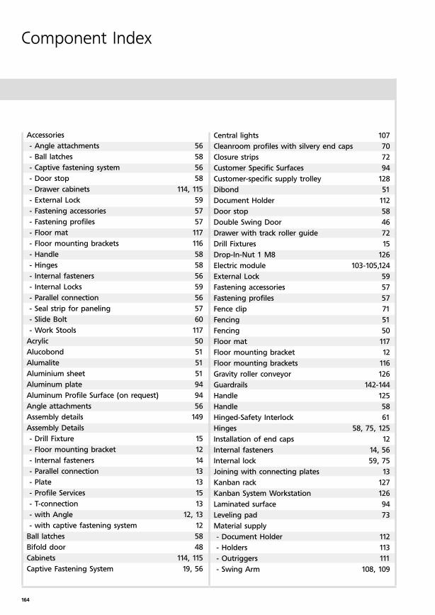
164
Component Index
Accessories
- Angle attachments 56
- Ball latches 58
- Captive fastening system 56
- Door stop 58
- Drawer cabinets 114, 115
- External Lock 59
- Fastening accessories 57
- Fastening profiles 57
- Floor mat 117
- Floor mounting brackets 116
- Handle 58
- Hinges 58
- Internal fasteners 56
- Internal Locks 59
- Parallel connection 56
- Seal strip for paneling 57
- Slide Bolt 60
- Work Stools 117
Acrylic 50
Alucobond 51
Alumalite 51
Aluminium sheet 51
Aluminum plate 94
Aluminum Profile Surface (on request) 94
Angle attachments 56
Assembly details 149
Assembly Details
- Drill Fixture 15
- Floor mounting bracket 12
- Internal fasteners 14
- Parallel connection 13
- Plate 13
- Profile Services 15
- T-connection 13
- with Angle 12, 13
- with captive fastening system 12
Ball latches 58
Bifold door 48
Cabinets 114, 115
Captive Fastening System 19, 56
Central lights 107
Cleanroom profiles with silvery end caps 70
Closure strips 72
Customer Specific Surfaces 94
Customer-specific supply trolley 128
Dibond 51
Document Holder 112
Door stop 58
Double Swing Door 46
Drawer with track roller guide 72
Drill Fixtures 15
Drop-In-Nut 1 M8 126
Electric module 103-105,124
External Lock 59
Fastening accessories 57
Fastening profiles 57
Fence clip 71
Fencing 51
Fencing 50
Floor mat 117
Floor mounting bracket 12
Floor mounting brackets 116
Gravity roller conveyor 126
Guardrails 142-144
Handle 125
Handle 58
Hinged-Safety Interlock 61
Hinges 58, 75, 125
Installation of end caps 12
Internal fasteners 14, 56
Internal lock 59, 75
Joining with connecting plates 13
Kanban rack 127
Kanban System Workstation 126
Laminated surface 94
Leveling pad 73
Material supply
- Document Holder 112
- Holders 113
- Outriggers 111
- Swing Arm 108, 109
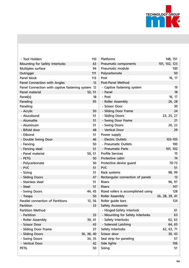
165
- Tool Holders 110
Mounting for Safety Interlocks 63
Multiplex surface 94
Outrigger 111
Panel block 113
Panel Connection with Angles 12
Panel Connection with captive fastening system 12
Panel material 50, 51
Panel(s) 18
Paneling 95
Paneling
- Acrylic 50
- Alucobond 51
- Alumalite 51
- Aluminum 51
- Bifold door 48
- Dibond 51
- Double Swing Door 46
- Fencing 50
- Fencing steel 51
- Panel material 50, 51
- PETG 50
- Polycarbonate 50
- PVC 51
- Sizing 51
- Sliding Doors 47
- Stainless steel 51
- Steel 51
- Swing Doors 44, 45
- Trespa 50
Parallel connection of Partitions 13, 56
Partition 33
Partition Method
- Partition 33
- Roller Assembly 39, 41
- Scissor Door 43
- Sliding Door Frame 37
- Sliding Doors 36, 38, 40
- Swing Doors 34, 35
- Vertical Door 42
PETG 50
Platforms 148, 151
Pneumatic components 101, 102, 123
Pneumatic module 100
Polycarbonate 50
Post 16, 17
Post-Panel Method
- Captive fastening system 19
- Panel 18
- Post 16, 17
- Roller Assembly 26, 28
- Scissor Door 30
- Sliding Door Frame 24
- Sliding Doors 23, 25, 27
- Swing Door Frame 21
- Swing Doors 20, 22
- Vertical Door 29
Power supply
- Electric Outlets 103-105
- Pneumatic Outlets 100
- Pneumatic Parts 101, 102
Profile Services 15
Protective cabin 74
Protective device guard 70-73
PVC 51
Rack systems 98, 99
Rectangular connection of panels 13
Risers 96, 97
Risers 147
Rized rollers is accomplished using 128
Roller Assembly 26, 28, 39, 41
Roller guide bars 124
Safety Accessories
- Hinged-Safety Interlock 61
- Mounting for Safety Interlocks 63
- Safety Interlocks 62, 63
- Solenoid Latching 64, 65
Safety Interlocks 62, 63, 71
Scissor door 30, 43
Seal strip for paneling 57
Side lights 106
Sizing 51
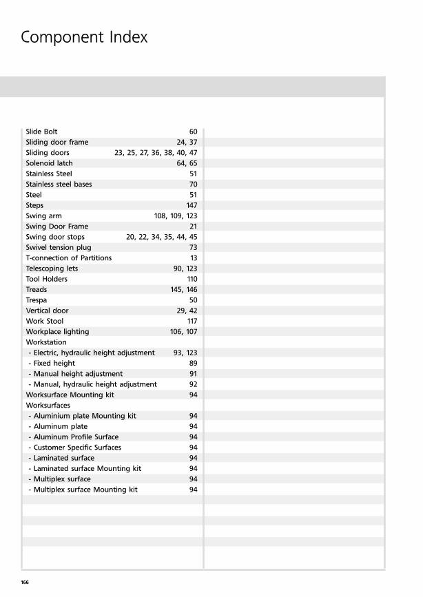
166
Component Index
Slide Bolt 60
Sliding door frame 24, 37
Sliding doors 23, 25, 27, 36, 38, 40, 47
Solenoid latch 64, 65
Stainless Steel 51
Stainless steel bases 70
Steel 51
Steps 147
Swing arm 108, 109, 123
Swing Door Frame 21
Swing door stops 20, 22, 34, 35, 44, 45
Swivel tension plug 73
T-connection of Partitions 13
Telescoping lets 90, 123
Tool Holders 110
Treads 145, 146
Trespa 50
Vertical door 29, 42
Work Stool 117
Workplace lighting 106, 107
Workstation
- Electric, hydraulic height adjustment 93, 123
- Fixed height 89
- Manual height adjustment 91
- Manual, hydraulic height adjustment 92
Worksurface Mounting kit 94
Worksurfaces
- Aluminium plate Mounting kit 94
- Aluminum plate 94
- Aluminum Profile Surface 94
- Customer Specific Surfaces 94
- Laminated surface 94
- Laminated surface Mounting kit 94
- Multiplex surface 94
- Multiplex surface Mounting kit 94
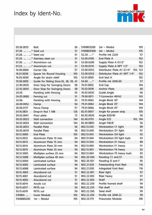
167
Index by Ident-No.
05.06.0015 Bolt 56
07.28. …. . ….* Steel cut 51
07.28. …. . ….* Steel cut 51
07.29. …. . ….* Stainless steel cut 51
07.30. …. . ….* Aluminium cut 51
07.33. …. . ….* Aluminium cut 51
14.00.0004 Corner Clip 57
16.01.0038 Spacer for Round Housing 105
16.05.0030 Angle for strain relief 105
19.00.0005 Guide for Sliding Door 26, 28, 39, 41
22.90.0035 Door Stop for Swinging Doors 58
22.92.0035 Door Stop for Swinging Doors 58
24.05. Paneling with Fencing 55
24.05.0000 Fencing cut 51
24.06. Paneling with Fencing 55
26.00.0052 Clamp 94
30.00.0117 Fence Clamp 57
34.16.0831 Drop-in Nut 1 M8 126
50.02.0041 Floor plate 75
50.03.0033 Wall connection 144
50.03.0034 Wall connection 144
50.05.0053 Parallel Plate 56
50.05.0070 Parallel Plate 56
50.12.0005 End Plate 105
50.13.0012 Aluminum Plate 10 mm 94
50.13.0013 Aluminum Plate 15 mm 94
50.13.0014 Aluminum Plate 20 mm 94
50.13.0015 Aluminum Plate 25 mm 94
50.13.5005 Multiplex surface 25 mm 94
50.13.5008 Multiplex surface 40 mm 94
50.13.6004 Laminated surface 94
50.13.6005 Laminated surface 94
50.13.6008 Laminated surface 94
50.15.3005 Alucobond cut 51
50.15.4001 Alucobond cut 51
50.15.4002 Alucobond cut 51
50.15.6014 Acrylic cut 50
50.15.6017 PETG cut 50
50.15.6019 PETG cut 50
5169BA .... Cover Module 105
5169BB0200 1er – Modul 105
5169BC0200 2er – Modul 105
5169BD0300 3er – Modul 105
52.20. ....* Profile mk 2220 57
53.00.0100 End Plate A 102
53.00.0200 Supply Plate A G1/2" 102
53.00.0210 Supply Plate A NPT 1/2" 102
53.00.0352 Distributor Plate A1 G1/4" 102, 123
53.00.0353 Distributor Plate A1 NPT 1/4" 102
53.01.0005 End Seal A 102
54.60. ....* Profile mk 2040.60 57
76.01.0002 End Cap 144
76.03.0018 Anchor Plate 60
76.03.0020 Guide Angle 60
79.00.0011 T-Connector 40/H2 143
79.01.0062 Angle Block 30° 144
79.01.0064 Angle Block 35° 144
79.01.0066 Angle Block 45° 144
82.01.0007 Angle for power strip 105
82.05.0026 Angle B20/40 56
82.40.0701 Angle E25 143, 144
82.40.0805 Angle F40/R 56
B02.13.030 Workstation C1 light 89
B02.13.040 Workstation D1 light 91
B02.13.043 Workstation D4 light 92
B02.13.044 Workstation D5 light hydr. 93
B02.13.050 Workstation E1 heavy 89
B02.13.060 Workstation F1 heavy 91
B02.13.063 Workstation F4 heavy 92
B02.13.064 Workstation F5 heavy hydr. 93
B02.20.500 Paneling C1 and E1 95
B02.20.501 Paneling D and F 95
B02.21.020 Freestanding Foot Rest 116
B02.21.030 Integrated Foot Rest 116
B02.22.001 Riser light 97
B02.22.002 Riser heavy 97
B02.22.003 Shelf 97
B02.22.250 Profile framed shelf 99
B02.22.255 Flat shelf 99
B02.22.260 Steel shelf 99
B02.22.265 Profile mk 2040.22 99
B02.23.179 Pneumatic Module 100
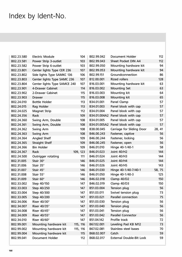
168
Index by Ident-No.
B02.23.580 Electric Module 104
B02.23.581 Power Strip 3-outlet 103
B02.23.582 Power Strip 6-outlet 103
B02.23.801 Center lights Type CER 236 107
B02.23.802 Side lights Type SAMKC 136 106
B02.23.803 Center lights Type SAMC 236 107
B02.23.804 Center lights Type SAMCE 240 107
B02.23.901 4-Drawer Cabinet 114
B02.23.902 2-Drawer Cabinet 115
B02.23.903 Drawer 115
B02.24.010 Bottle Holder 113
B02.24.015 Rag Holder 113
B02.24.025 Magnet Strip 112
B02.24.356 Rack 109
B02.24.360 Swing Arm, Double 108
B02.24.361 Swing Arm, Double 108
B02.24.362 Swing Arm 108
B02.24.363 Swing Arm 108
B02.24.364 Angled Shelf 109
B02.24.365 Straight Shelf 109
B02.24.366 Bin Holder 109
B02.24.367 Rack 109, 123
B02.24.500 Outrigger rotating 111
B02.31.005 Stair 30° 146
B02.31.006 Stair 35° 146
B02.31.007 Stair 45° 146
B02.31.008 Stair 55° 146
B02.31.009 Stair 60° 146
B02.33.002 Step 40/150 147
B02.33.003 Step 40/250 147
B02.33.004 Step 40/300 147
B02.33.005 Step 40/200 147
B02.34.006 Riser 40/30° 147
B02.34.007 Riser 40/35° 147
B02.34.008 Riser 40/45° 147
B02.34.009 Riser 40/55° 147
B02.34.010 Riser 40/60° 147
B02.99.001 Mounting hardware kit 115, 116
B02.99.002 Mounting hardware kit 115, 116
B02.99.004 Mounting hardware kit 115
B02.99.041 Document Holder 112
B02.99.042 Document Holder 112
B02.99.043 Sheet Pocket DIN A4 112
B02.99.050 Mounting hardware kit 94
B02.99.053 Mounting hardware kit 94
B02.99.151 Groundconnection 86
B12.00.001 Rized rollers 128
B16.03.001 Mounting hardware kit 63
B16.03.002 Mounting Set 63
B16.03.003 Mounting kit 64
B16.03.008 Mounting kit 65
B34.01.001 Panel Clamp 57
B34.01.003 Panel block with cap 57
B34.01.004 Panel block with cap 57
B34.01.004A2 Panel block with cap 57
B34.01.005 Panel block with cap 57
B34.01.005A2 Panel block with cap 57
B38.00.045 Carriage for Sliding Door 28, 41
B46.00.243 Fastener, captive 56
B46.00.244 Fastener, locking 56
B46.00.245 Fastener, open 56
B46.01.010 Hinge 40-1/40-1 58
B46.01.023 Joint 40/H2 144
B46.01.024 Joint 40/H3 144
B46.01.025 Joint 40/H4 144
B46.01.026 Joint 40/H5 143
B46.01.030 Hinge 40-1/40-7/40-1 58, 75
B46.01.050 Hinge 40-1/40-3 125
B46.02.018 Clamp 40/D2 150
B46.02.019 Clamp 40/D3 150
B51.03.004 Tension plug 56
B51.03.011 Swivel tension plug 73
B51.03.021 Parallel connection 75
B51.03.030 Tension plug 56
B51.03.040 Tension plug 56
B51.03.041 Tension plug 56
B51.03.042 Parallel Connector 56
B51.04.142 Profile track 72
B67.02.001 Leveling Pad KB M12 73
B67.02.081 Stainless steel bases 70
B68.02.007 Catch 59
B68.02.017 External Double-Bit Lock 59
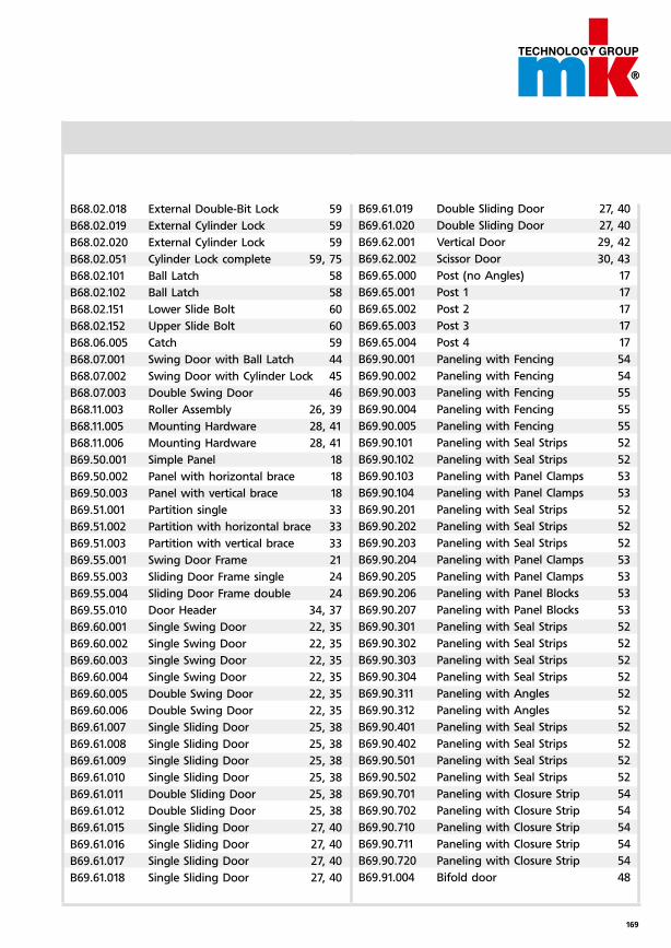
169
B68.02.018 External Double-Bit Lock 59
B68.02.019 External Cylinder Lock 59
B68.02.020 External Cylinder Lock 59
B68.02.051 Cylinder Lock complete 59, 75
B68.02.101 Ball Latch 58
B68.02.102 Ball Latch 58
B68.02.151 Lower Slide Bolt 60
B68.02.152 Upper Slide Bolt 60
B68.06.005 Catch 59
B68.07.001 Swing Door with Ball Latch 44
B68.07.002 Swing Door with Cylinder Lock 45
B68.07.003 Double Swing Door 46
B68.11.003 Roller Assembly 26, 39
B68.11.005 Mounting Hardware 28, 41
B68.11.006 Mounting Hardware 28, 41
B69.50.001 Simple Panel 18
B69.50.002 Panel with horizontal brace 18
B69.50.003 Panel with vertical brace 18
B69.51.001 Partition single 33
B69.51.002 Partition with horizontal brace 33
B69.51.003 Partition with vertical brace 33
B69.55.001 Swing Door Frame 21
B69.55.003 Sliding Door Frame single 24
B69.55.004 Sliding Door Frame double 24
B69.55.010 Door Header 34, 37
B69.60.001 Single Swing Door 22, 35
B69.60.002 Single Swing Door 22, 35
B69.60.003 Single Swing Door 22, 35
B69.60.004 Single Swing Door 22, 35
B69.60.005 Double Swing Door 22, 35
B69.60.006 Double Swing Door 22, 35
B69.61.007 Single Sliding Door 25, 38
B69.61.008 Single Sliding Door 25, 38
B69.61.009 Single Sliding Door 25, 38
B69.61.010 Single Sliding Door 25, 38
B69.61.011 Double Sliding Door 25, 38
B69.61.012 Double Sliding Door 25, 38
B69.61.015 Single Sliding Door 27, 40
B69.61.016 Single Sliding Door 27, 40
B69.61.017 Single Sliding Door 27, 40
B69.61.018 Single Sliding Door 27, 40
B69.61.019 Double Sliding Door 27, 40
B69.61.020 Double Sliding Door 27, 40
B69.62.001 Vertical Door 29, 42
B69.62.002 Scissor Door 30, 43
B69.65.000 Post (no Angles) 17
B69.65.001 Post 1 17
B69.65.002 Post 2 17
B69.65.003 Post 3 17
B69.65.004 Post 4 17
B69.90.001 Paneling with Fencing 54
B69.90.002 Paneling with Fencing 54
B69.90.003 Paneling with Fencing 55
B69.90.004 Paneling with Fencing 55
B69.90.005 Paneling with Fencing 55
B69.90.101 Paneling with Seal Strips 52
B69.90.102 Paneling with Seal Strips 52
B69.90.103 Paneling with Panel Clamps 53
B69.90.104 Paneling with Panel Clamps 53
B69.90.201 Paneling with Seal Strips 52
B69.90.202 Paneling with Seal Strips 52
B69.90.203 Paneling with Seal Strips 52
B69.90.204 Paneling with Panel Clamps 53
B69.90.205 Paneling with Panel Clamps 53
B69.90.206 Paneling with Panel Blocks 53
B69.90.207 Paneling with Panel Blocks 53
B69.90.301 Paneling with Seal Strips 52
B69.90.302 Paneling with Seal Strips 52
B69.90.303 Paneling with Seal Strips 52
B69.90.304 Paneling with Seal Strips 52
B69.90.311 Paneling with Angles 52
B69.90.312 Paneling with Angles 52
B69.90.401 Paneling with Seal Strips 52
B69.90.402 Paneling with Seal Strips 52
B69.90.501 Paneling with Seal Strips 52
B69.90.502 Paneling with Seal Strips 52
B69.90.701 Paneling with Closure Strip 54
B69.90.702 Paneling with Closure Strip 54
B69.90.710 Paneling with Closure Strip 54
B69.90.711 Paneling with Closure Strip 54
B69.90.720 Paneling with Closure Strip 54
B69.91.004 Bifold door 48
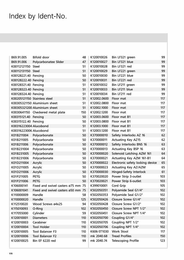
170
Index by Ident-No.
B69.91.005 Bifold door 48
B69.91.006 Polycarbonatee Slider 47
K00112121150 Steel 51
K00112131150 Steel 51
K00128221.40 Fencing 50
K00128222.40 Fencing 50
K00128321.40 Fencing 51
K00128323.40 Fencing 51
K00128324.40 Fencing 51
K00205121150 Stainless steel 51
K00305321150 Aluminium sheet 51
K00305321200 Aluminium sheet 51
K0030641150 Checkered metal plate 150
K00315121.40 Fencing 50
K00315122.40 Fencing 50
K00316223004 Alucobond 51
K00316223006 Alucobond 51
K01B211004 Polycarbonate 50
K01B211005 Polycarbonate 50
K01B211006 Polycarbonate 50
K01B231004 Polycarbonate 50
K01B231005 Polycarbonate 50
K01B231006 Polycarbonate 50
K01D211004 Acrylic 50
K01D211005 Acrylic 50
K01D211006 Acrylic 50
K01P211005 PETG 50
K01P211006 PETG 50
K106000141 Fixed and swivel casters ø75 mm 75
K106001041 Fixed and swivel casters ø50 mm 75
K110000009 Handle 58
K110000020 Handle 125
K112510020 Wood Screws ø4x25 94
K115010093 O-Ring 102
K117055000 Cylinder 59
K120010001 Diameters 110
K120010003 Carabiner 110
K120010004 Tool Holder 110
K120010005 Tool Balancer F3 110
K120010006 Tool Balancer F2 110
K120010025 Bin EF 6220 red 99
K120010026 Bin LF321 green 99
K120010027 Bin LF321 blue 99
K120010028 Bin LF321 red 99
K120010029 Bin LF221 green 99
K120010030 Bin LF221 blue 99
K120010031 Bin LF221 red 99
K120010032 Bin LF211 green 99
K120010033 Bin LF211 blue 99
K120010034 Bin LF211 red 99
K12002.0600 Floor mat 117
K12002.0800 Floor mat 117
K12002.1000 Floor mat 117
K12002.1200 Floor mat 117
K12003.0600 Floor mat B1 117
K12003.0800 Floor mat B1 117
K12003.1000 Floor mat B1 117
K12003.1200 Floor mat B1 117
K370000010 Safety Interlocks AZ 16 62
K370000011 Actuating Key AZ15 62
K370000012 Safety Interlocks BNS 16 63
K370000013 Actuating Key BSP 16 63
K370000020 Solenoid Latching AZM 161 64
K370000021 Actuating Key AZM 161-B1 64
K370000022 Electronic safety locking device 65
K370000023 Actuating Key AZ/AZM 65
K370000030 Hinged-Safety Interlock 61
K370020020 Power Strip 3-outlet 103
K370020021 Power Strip 6-outlet 103
K399010001 Cord Grip 105
K502050351 Polyamide Seal G1/4" 102
K502050353 Polyamide Seal G1/2" 102
K502050426 Closure Screw G1/4" 102
K502050428 Closure Screw G1/2" 102
K502050450 Closure Screw NPT 1/2" 102
K502050451 Closure Screw NPT 1/4" 102
K502050700 Coupling G1/4" 102
K502050705 Coupling NPT 1/2" 102
K502050706 Coupling NPT 1/4" 102
K606-ST1030 Work Stool 117
mk 2040.68 Tread Profiles 150
mk 2040.74 Telescoping Profile 123
171
mk 2533 Keeper 59
mk 2544 Fence Clip 57
mk 3008 Profile edging 57
mk 3008SI Profile edging 57
mk 3015 Closure strip 72
mk 3020 Seal Strip 57
mk 3021 Seal Strip 57
mk 3034 Closure Strip 57
P57.01.000 Stainless Steel 51
P57.02.000 Steel 51
P90.00.007 Fencing 51
P90.00.008 Fencing 51
P90.00.009 Fencing 51
P90.00.010 Fencing 51
P90.03.002 Polycarbonate 50
P90.03.003 Polycarbonate 50
P90.04.001 Alumalite 51
P90.05.001 Acrylic 50
P90.06.001 Dibond 51
P90.07.001 PVC 51
P90.07.002 PVC 51
P90.07.003 PVC 51
P90.07.004 PVC 51
P90.08.001 Trespa silver 50

Maschinenbau Kitz GmbH
Headquarters of the
mk Technology Group
Glockenstraße 84
53844 Troisdorf
Germany
Phone +49 228 4598-0
Fax +49 228 453145
www.mk-group.com