Embed Size (px)
Citation preview

MIXING CONSOLE
Owner’s Manual
Making the Most Of Your MixerPages 6 to 18
E
MG16-6FX.book Page 1 Saturday, January 25, 2003 10:13 AM
2
MG16-6FX.book Page 2 Saturday, January 25, 2003 10:13 AM
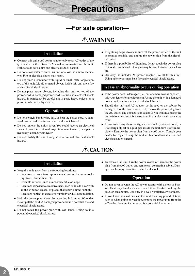
Precautions
—For safe operation—
WARNING
Connect this unit’s AC power adaptor only to an AC outlet of thetype stated in this Owner’s Manual or as marked on the unit.Failure to do so is a fire and electrical shock hazard.
Do not allow water to enter this unit or allow the unit to becomewet. Fire or electrical shock may result.
Do not place a container with liquid or small metal objects ontop of this unit. Liquid or metal objects inside this unit are a fireand electrical shock hazard.
Do not place heavy objects, including this unit, on top of thepower cord. A damaged power cord is a fire and electrical shockhazard. In particular, be careful not to place heavy objects on apower cord covered by a carpet.
Do not scratch, bend, twist, pull, or heat the power cord. A dam-aged power cord is a fire and electrical shock hazard.
Do not remove the unit’s cover. You could receive an electricalshock. If you think internal inspection, maintenance, or repair isnecessary, contact your dealer.
Do not modify the unit. Doing so is a fire and electrical shockhazard.
If lightning begins to occur, turn off the power switch of the unitas soon as possible, and unplug the power plug from the electri-cal outlet.
If there is a possibility of lightning, do not touch the power plugif it is still connected. Doing so may be an electrical shock haz-ard.
Use only the included AC power adaptor (PA-30) for this unit.Using other types may be a fire and electrical shock hazard.
If the power cord is damaged (i.e., cut or a bare wire is exposed),ask your dealer for a replacement. Using the unit with a damagedpower cord is a fire and electrical shock hazard.
Should this unit and AC adaptor be dropped or the cabinet bedamaged, turn the power switch off, remove the power plug fromthe AC outlet, and contact your dealer. If you continue using theunit without heeding this instruction, fire or electrical shock mayresult.
If you notice any abnormality, such as smoke, odor, or noise, orif a foreign object or liquid gets inside the unit, turn it off imme-diately. Remove the power plug from the AC outlet. Consult yourdealer for repair. Using the unit in this condition is a fire andelectrical shock hazard.
CAUTION
Keep this unit away from the following locations:- Locations exposed to oil splashes or steam, such as near cook-
ing stoves, humidifiers, etc.- Unstable surfaces, such as a wobbly table or slope.- Locations exposed to excessive heat, such as inside a car with
all the windows closed, or places that receive direct sunlight.- Locations subject to excessive humidity or dust accumulation.
Hold the power plug when disconnecting it from an AC outlet.Never pull the cord. A damaged power cord is a potential fire andelectrical shock hazard.
Do not touch the power plug with wet hands. Doing so is apotential electrical shock hazard.
To relocate the unit, turn the power switch off, remove the powerplug from the AC outlet, and remove all connecting cables. Dam-aged cables may cause fire or electrical shock.
Do not cover or wrap the AC power adaptor with a cloth or blan-ket. Heat may build up under the cloth or blanket, melting thecase, or causing fire. Use only in a well-ventilated environment.
If you know you will not use this unit for a log period of time,such as when going on vacation, remove the power plug from theAC outlet. Leaving it connected is a potential fire hazard.
Installation
Operation
In case an abnormality occurs during operation
Installation
Operation
MG16/6FX

Precautions
MG16-6FX.book Page 3 Saturday, January 25, 2003 10:13 AM
—For correct operation —
XLR-type connectors are wired as followsPin 1: ground; Pin 2: hot (+); Pin 3: cold (–).
INSERT TRS phone jacks are wired as followsSleeve: ground; Tip: send; Ring: return.
The performance of components with movable contacts—suchas switches, rotary controls, faders, and connectors—deterioratesover time. While the rate of wear may vary greatly according tousage conditions, some amount of wear is unavoidable. Whenparts wear out, consult your dealer about appropriate replace-ments.
Use of a mobile phone near this unit may induce noise. If noiseoccurs, move the phone further from the unit.
Copying of commercially available music data and/or digital audio files, except for personal use, is strictly prohibited.
Illustrations in this manual are for explanatory purposes only, and may not match the actual appearance of the product during operation.
Company names and product names used in this Owner’s Manual are trademarks or registered trademarks of their respective owners.
* This applies only to products distributed by YAMAHA CORPORATION OF AMERICA. (class B)
• This applies only to products distributed by Yamaha-Kemble Music (U.K.) Ltd. (2 wires).
Connector pin assignments
Replacement of Consumable Parts
Interference from Cell Phones
Always turn the power off when the mixer is not in use.
Even when the power switch is in the “STANDBY” position, electricity is still flowing to the mixer at the minimum level. When you arenot using the mixer for a long time, make sure you unplug the AC power adaptor from the wall AC outlet.
IMPORTANT NOTICE FOR THE UNITED KINGDOMConnecting the Plug and Cord
IMPORTANT. The wires in this mains lead are coloured in accordance with the following code:BLUE : NEUTRALBROWN : LIVE
As the colours of the wires in the mains lead of this apparatus may not correspond with the coloured makings identifying the terminals in yourplug proceed as follows:The wire which is coloured BLUE must be connected to the terminal which is marked with the letter N or coloured BLACK.The wire which is coloured BROWN must be connected to the terminal which is marked with the letter L or coloured RED.Making sure that neither core is connected to the earth terminal of the three pin plug.
1. IMPORTANT NOTICE: DO NOT MODIFY THIS UNIT!This product, when installed as indicated in the instructions con-tained in this manual, meets FCC requirements. Modifications not expressly approved by Yamaha may void your authority, granted by the FCC, to use the product.
2. IMPORTANT: When connecting this product to accessories and/or another product use only high quality shielded cables. Cable/s supplied with this product MUST be used. Follow all installation instructions. Failure to follow instructions could void your FCC authorization to use this product in the USA.
3. NOTE: This product has been tested and found to comply with the requirements listed in FCC Regulations, Part 15 for Class “B” digital devices. Compliance with these requirements provides a reasonable level of assurance that your use of this product in a residential environment will not result in harmful interference with other electronic devices. This equipment generates/uses radio frequencies and, if not installed and used according to the instructions found in the users manual, may cause interference harmful to the operation of other electronic devices. Compliance
with FCC regulations does not guarantee that interference will not occur in all installations. If this product is found to be the source of interference, which can be determined by turning the unit “OFF” and “ON”, please try to eliminate the problem by using one of the following measures:Relocate either this product or the device that is being affected by the interference. Utilize power outlets that are on different branch (circuit breaker or fuse) circuits or install AC line filter/s.In the case of radio or TV interference, relocate/reorient the antenna. If the antenna lead-in is 300 ohm ribbon lead, change the lead-in to co-axial type cable.If these corrective measures do not produce satisfactory results, please contact the local retailer authorized to distribute this type of product. If you can not locate the appropriate retailer, please contact Yamaha Corporation of America, Electronic Service Divi-sion, 6600 Orangethorpe Ave, Buena Park, CA90620The above statements apply ONLY to those products distributed by Yamaha Corporation of America or its subsidiaries.
FCC INFORMATION (U.S.A.)
MG16/6FX3
4
MG16-6FX.book Page 4 Saturday, January 25, 2003 10:13 AM
Introduction
Thank you for your purchase of the YAMAHA MG16/6FX mixing console. This mixing consolecombines ease of operation with support for multiple usage environments, and is ideal for SRsetups, installed systems, and many other such applications.
Please read through this Owner’s Manual carefully before beginning use, so that you will beable to take full advantage of this mixer’s superlative features and enjoy trouble-free operationfor years to come.
The MG16/6FX provides 16 input channels and mixes the sig-nals into Stereo and Group outputs.
With high-quality digital effects built in, the MG16/6FX candeliver a wide range of sound variations even when used on itsown. It also includes an EFFECT SEND jack that can be used toconnect an external effector.
The monitor includes a convenient C-R OUT jack. This jack canbe used to monitor the main Stereo output, the PFL signal, or theGroup 1-2 signals.
The mixer includes dual AUX SEND jacks and a singleRETURN jack. The two independent AUX buses may be used assends to external effectors and monitor systems.
Phantom power supply enables easy connection to condensermicrophones that run on external power.
The mixer provides channel-specific INSERT I/O jacks for inputchannels 1 to 8. These jacks make it possible to insert differenteffectors into different channels.
Input channels 1 to 8, 9/10, and 11/12 are each equipped withboth an XLR mic input jack and a TRS phone-type line jack.Input channels 13/14 and 15/16 are each equipped with both aTRS line input jack and an RCA line input jack. This wideassortment of connectors enables connection to many differentdevices, from microphones to line-level devices to stereo-outputsynthesizers.
Introduction ............................................................... 4
Features ............................................................... 4
Contents .............................................................. 4
Before Turning on the Mixer ................................. 5
Turning the Power On .......................................... 5
Making the Most Of Your Mixer ................................. 6
1A Place For Everything and Everything In Its Place ....................................................... 7
2Where Your Signal Goes Once It’s Inside the Box .......................................................... 10
3 The First Steps in Achieving Great Sound .... 11
4External Effects, Monitor Mixes, and Groups .................................................... 13
5Making Better Mixes ...................................... 16
Front & Rear Panels ................................................ 19
Channel Control Section .................................... 19
Master Control Section ...................................... 21
Rear Input/Output Section ................................. 23
Setting Up ............................................................... 25
Setup Procedure ................................................ 25
Setup Examples ................................................ 25
Rack Mounting ................................................... 27
Appendix ................................................................. 28
Specifications .................................................... 28
Dimensional Diagrams ....................................... 30
Block Diagram and Level Diagram .................... 31
Features Contents
MG16/6FX
Introduction
MG16-6FX.book Page 5 Saturday, January 25, 2003 10:13 AM
(1) Be sure that the mixer’s power switch is in the STANDBY position.
Use only the PA-30 adaptor included with this mixer.Use of a different adaptor may result in equipmentdamage, overheating, or fire.
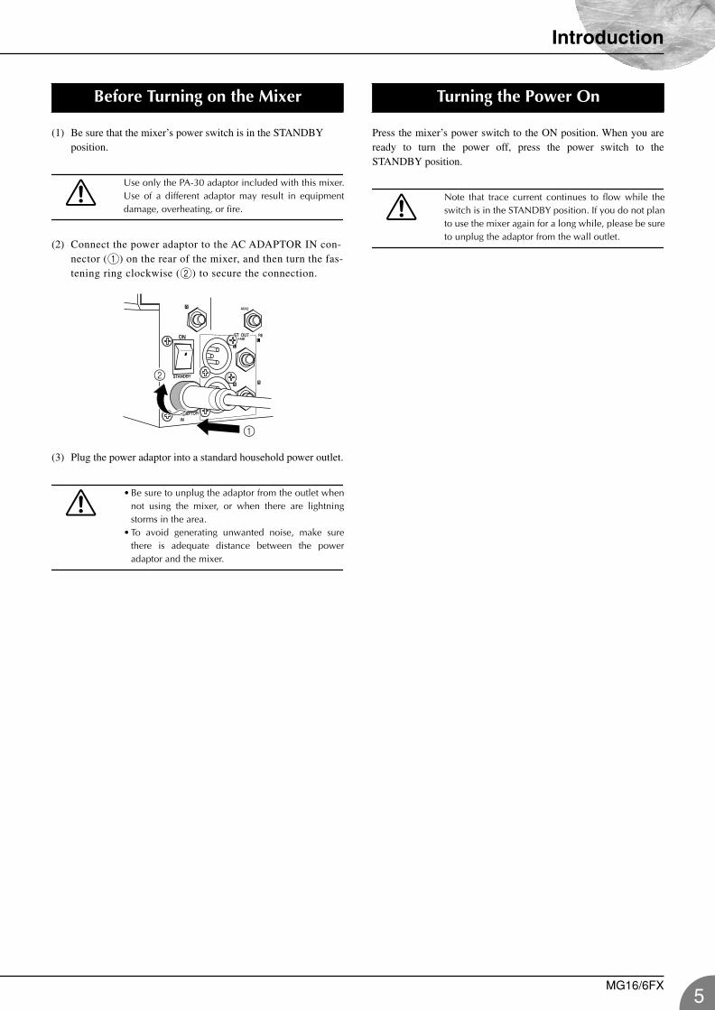
(2) Connect the power adaptor to the AC ADAPTOR IN con-nector (1) on the rear of the mixer, and then turn the fas-tening ring clockwise (2) to secure the connection.
(3) Plug the power adaptor into a standard household power outlet.
• Be sure to unplug the adaptor from the outlet whennot using the mixer, or when there are lightningstorms in the area.
• To avoid generating unwanted noise, make surethere is adequate distance between the poweradaptor and the mixer.
Press the mixer’s power switch to the ON position. When you areready to turn the power off, press the power switch to theSTANDBY position.
Note that trace current continues to flow while theswitch is in the STANDBY position. If you do not planto use the mixer again for a long while, please be sureto unplug the adaptor from the wall outlet.
Before Turning on the Mixer
1
2
Turning the Power On
MG16/6FX5
6
MG16-6FX.book Page 6 Saturday, January 25, 2003 10:13 AM
Making the Most Of Your Mixer
An Introduction
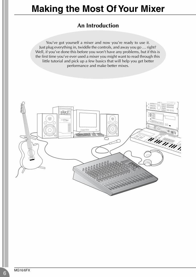
You’ve got yourself a mixer and now you’re ready to use it. Just plug everything in, twiddle the controls, and away you go … right?
Well, if you’ve done this before you won’t have any problems, but if this is the first time you’ve ever used a mixer you might want to read through this
little tutorial and pick up a few basics that will help you get better performance and make better mixes.
MG16/6FX
Making the Most Of Your Mixer
MG16-6FX.book Page 7 Saturday, January 25, 2003 10:13 AM
A Place For Everything and Everything In Its Place
1-1. A Plethora Of Connectors—What Goes Where?
Questions you’re likely to encounter when setting up a system for the first time might include “Why allthese different types of connectors on the back of my mixer?” and “What’s the difference?”.
Let’s start by taking a look at the most common connector types.
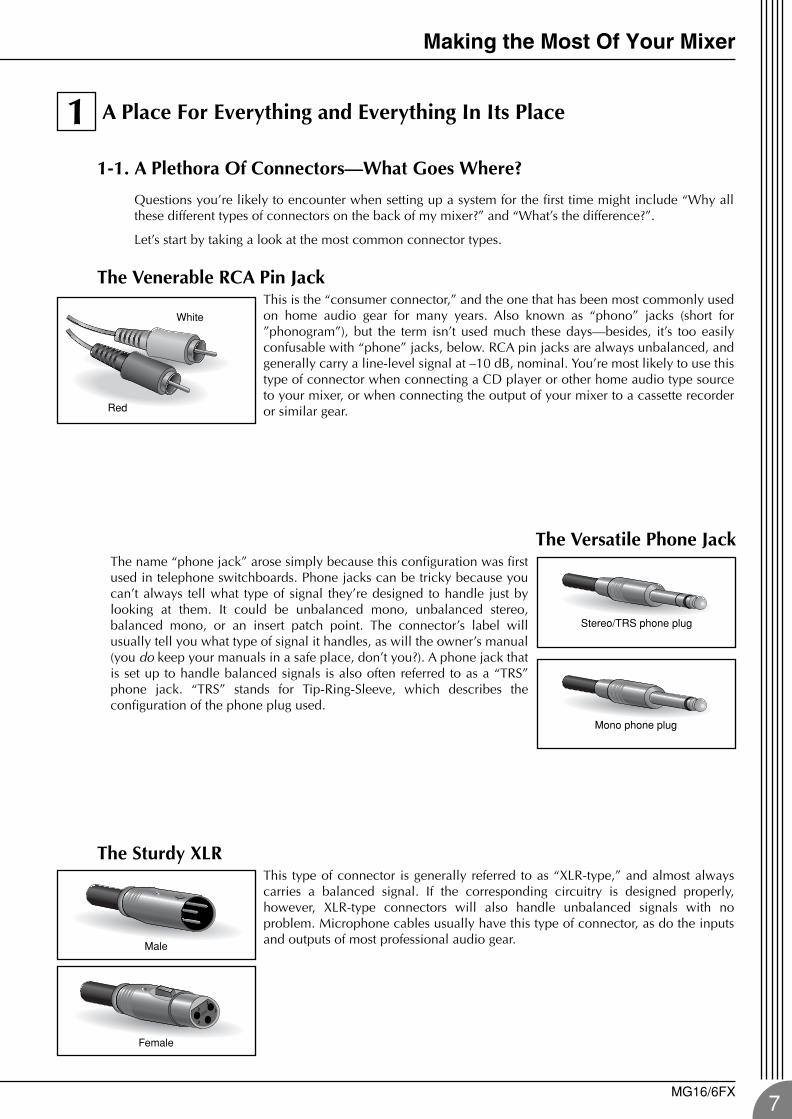
The Venerable RCA Pin JackThis is the “consumer connector,” and the one that has been most commonly usedon home audio gear for many years. Also known as “phono” jacks (short for”phonogram”), but the term isn’t used much these days—besides, it’s too easilyconfusable with “phone” jacks, below. RCA pin jacks are always unbalanced, andgenerally carry a line-level signal at –10 dB, nominal. You’re most likely to use thistype of connector when connecting a CD player or other home audio type sourceto your mixer, or when connecting the output of your mixer to a cassette recorderor similar gear.
The Versatile Phone JackThe name “phone jack” arose simply because this configuration was firstused in telephone switchboards. Phone jacks can be tricky because youcan’t always tell what type of signal they’re designed to handle just bylooking at them. It could be unbalanced mono, unbalanced stereo,balanced mono, or an insert patch point. The connector’s label willusually tell you what type of signal it handles, as will the owner’s manual(you do keep your manuals in a safe place, don’t you?). A phone jack thatis set up to handle balanced signals is also often referred to as a “TRS”phone jack. “TRS” stands for Tip-Ring-Sleeve, which describes theconfiguration of the phone plug used.
The Sturdy XLRThis type of connector is generally referred to as “XLR-type,” and almost alwayscarries a balanced signal. If the corresponding circuitry is designed properly,however, XLR-type connectors will also handle unbalanced signals with noproblem. Microphone cables usually have this type of connector, as do the inputsand outputs of most professional audio gear.
1
White
Red
Stereo/TRS phone plug
Mono phone plug
Male
Female
MG16/6FX7
Making the Most Of Your Mixer
8
MG16-6FX.book Page 8 Saturday, January 25, 2003 10:13 AM
1-2. Balanced, Unbalanced—What’s the Difference?
In a word: “noise.” The whole point of balanced lines is noise rejection, and it’s something they’re verygood at. Any length of wire will act as an antenna to pick up the random electromagnetic radiation we’reconstantly surrounded by: radio and TV signals as well as spurious electromagnetic noise generated bypower lines, motors, electric appliances, computer monitors, and a variety of other sources. The longerthe wire, the more noise it is likely to pick up. That’s why balanced lines are the best choice for longcable runs. If your “studio” is basically confined to your desktop and all connections are no more than ameter or two in length, then unbalanced lines are fine—unless you’re surrounded by extremely high lev-els of electromagnetic noise. Another place balanced lines are almost always used is in microphonecables. The reason for this is that the output signal from most microphones is very small, so even a tinyamount of noise will be relatively large, and will be amplified to an alarming degree in the mixer’s high-gain head amplifier.
To summarize:Microphones: Use balanced lines. Short line-level runs: Unbalanced lines are fine if you’re in a relatively noise-free environment. Long line-level runs: The ambient electromagnetic noise level will be the ultimate deciding factor, but
balanced is best.
How Do Balanced Lines Reject Noise?** Skip this section if technical details make you queasy. **
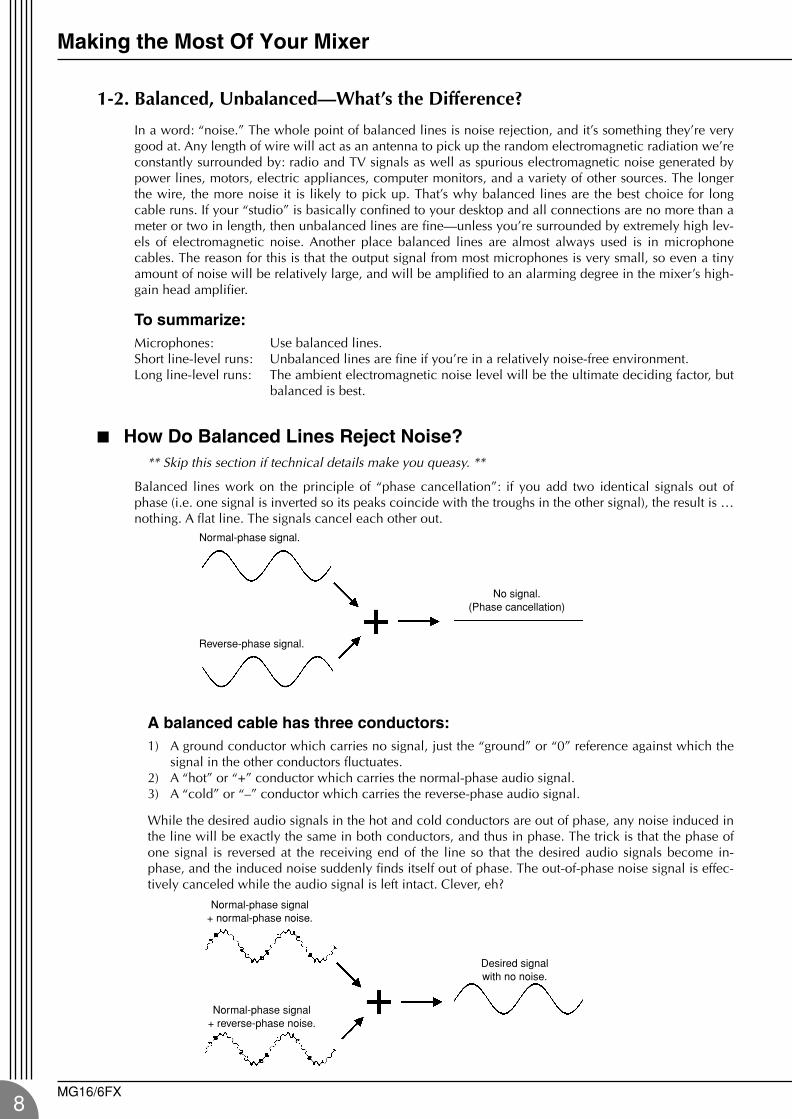
Balanced lines work on the principle of “phase cancellation”: if you add two identical signals out ofphase (i.e. one signal is inverted so its peaks coincide with the troughs in the other signal), the result is …nothing. A flat line. The signals cancel each other out.
A balanced cable has three conductors:1) A ground conductor which carries no signal, just the “ground” or “0” reference against which the
signal in the other conductors fluctuates.2) A “hot” or “+” conductor which carries the normal-phase audio signal.3) A “cold” or “–” conductor which carries the reverse-phase audio signal.
While the desired audio signals in the hot and cold conductors are out of phase, any noise induced inthe line will be exactly the same in both conductors, and thus in phase. The trick is that the phase ofone signal is reversed at the receiving end of the line so that the desired audio signals become in-phase, and the induced noise suddenly finds itself out of phase. The out-of-phase noise signal is effec-tively canceled while the audio signal is left intact. Clever, eh?
Normal-phase signal.
Reverse-phase signal.
No signal.(Phase cancellation)
Normal-phase signal+ normal-phase noise.
Normal-phase signal+ reverse-phase noise.
Desired signal with no noise.
MG16/6FX
Making the Most Of Your Mixer
MG16-6FX.book Page 9 Saturday, January 25, 2003 10:13 AM
1-3. Signal Levels—Decibel Do’s and Don’ts
From the moment you start dealing with things audio, you’ll have to deal with the term “decibel” and itsabbreviation, “dB”. Things can get confusing because decibels are a very versatile unit of measure usedto describe acoustic sound pressure levels as well as electronic signal levels. To make matters worse thereare a number of variations: dBu, dBV, dBm. Fortunately, you don’t need to be an expert to make thingswork. Here are a few basics you should keep in mind:
“Consumer” gear (such as home audio equipment) usually has line inputs and outputs with a nomi-nal (average) level of –10 dB.
Professional audio gear usually has line inputs and outputs with a nominal level of +4 dB.
You should always feed –10 dB inputs with a –10 dB signal. If you feed a +4 dB signal into a –10 dBinput you are likely to overload the input.
You should always feed +4 dB inputs with a +4 dB signal. A –10 dB signal is too small for a +4 dBinput, and will result in less-than-optimum performance.
Many professional and semi-professional devices have level switches on the inputs and/or outputsthat let you select –10 or +4 dB. Be sure to set these switches to match the level of the connectedequipment.
Inputs that feature a “Gain” control—such as the mono-channel inputs on your Yamaha mixer—willaccept a very wide range of input levels because the control can be used to match the input’s sensi-tivity to the signal. More on this later.
MG16/6FX9
Making the Most Of Your Mixer
10
MG16-6FX.book Page 10 Saturday, January 25, 2003 10:13 AM
Where Your Signal Goes Once It’s Inside the Box
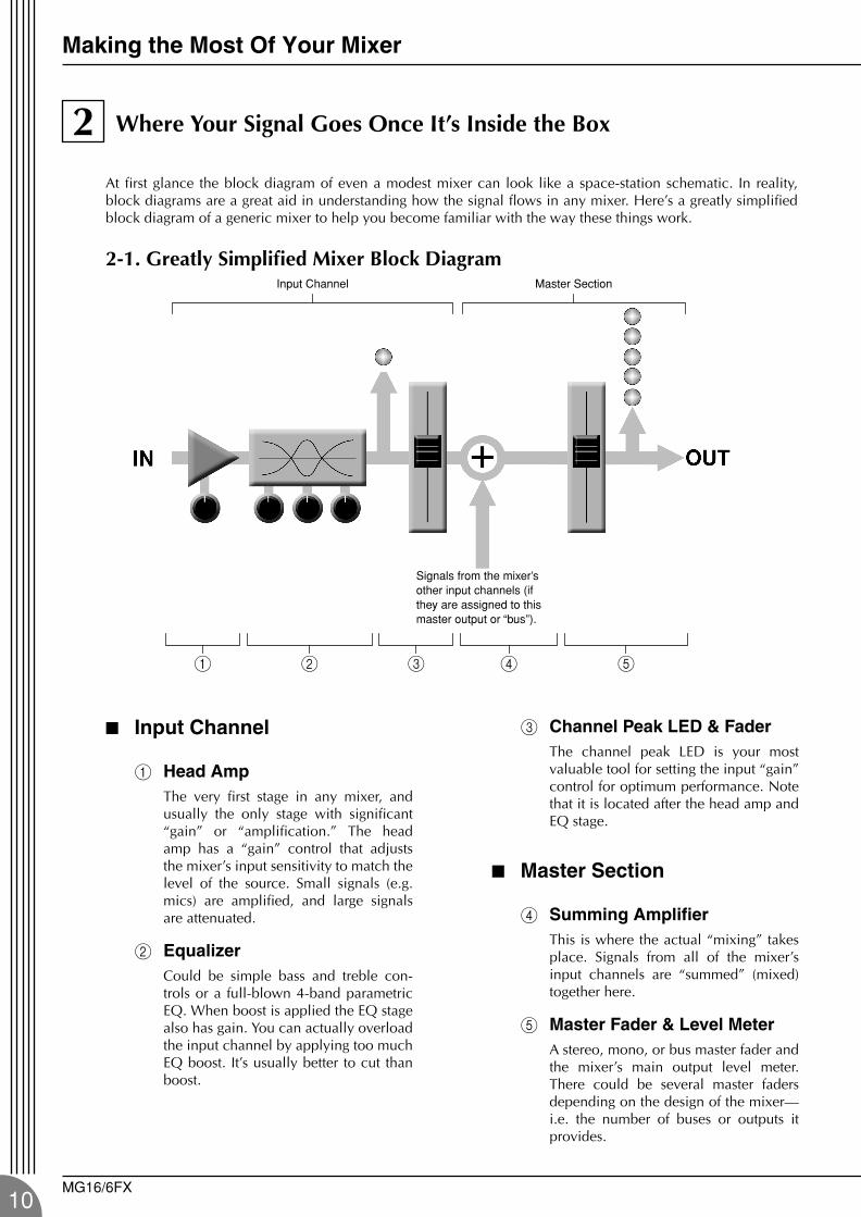
At first glance the block diagram of even a modest mixer can look like a space-station schematic. In reality,block diagrams are a great aid in understanding how the signal flows in any mixer. Here’s a greatly simplifiedblock diagram of a generic mixer to help you become familiar with the way these things work.
2-1. Greatly Simplified Mixer Block Diagram
Input Channel
1 Head AmpThe very first stage in any mixer, andusually the only stage with significant“gain” or “amplification.” The headamp has a “gain” control that adjuststhe mixer’s input sensitivity to match thelevel of the source. Small signals (e.g.mics) are amplified, and large signalsare attenuated.
2 EqualizerCould be simple bass and treble con-trols or a full-blown 4-band parametricEQ. When boost is applied the EQ stagealso has gain. You can actually overloadthe input channel by applying too muchEQ boost. It’s usually better to cut thanboost.
3 Channel Peak LED & FaderThe channel peak LED is your mostvaluable tool for setting the input “gain”control for optimum performance. Notethat it is located after the head amp andEQ stage.
Master Section
4 Summing AmplifierThis is where the actual “mixing” takesplace. Signals from all of the mixer’sinput channels are “summed” (mixed)together here.
5 Master Fader & Level MeterA stereo, mono, or bus master fader andthe mixer’s main output level meter.There could be several master fadersdepending on the design of the mixer—i.e. the number of buses or outputs itprovides.
2
1 2 3 4 5
Input Channel Master Section
Signals from the mixer’s other input channels (if they are assigned to this master output or “bus”).
MG16/6FX
Making the Most Of Your Mixer
MG16-6FX.book Page 11 Saturday, January 25, 2003 10:13 AM
The First Steps in Achieving Great Sound
Before you even consider EQ and effects, or even the overall mix, it is important to make sure that levels areproperly set for each individual source. This can’t be stressed enough—initial level setup is vitally important forachieving optimum performance from your mixer! Here’s why … and how.
3-1. The Head Amplifier “Gain” Control Is the Key!
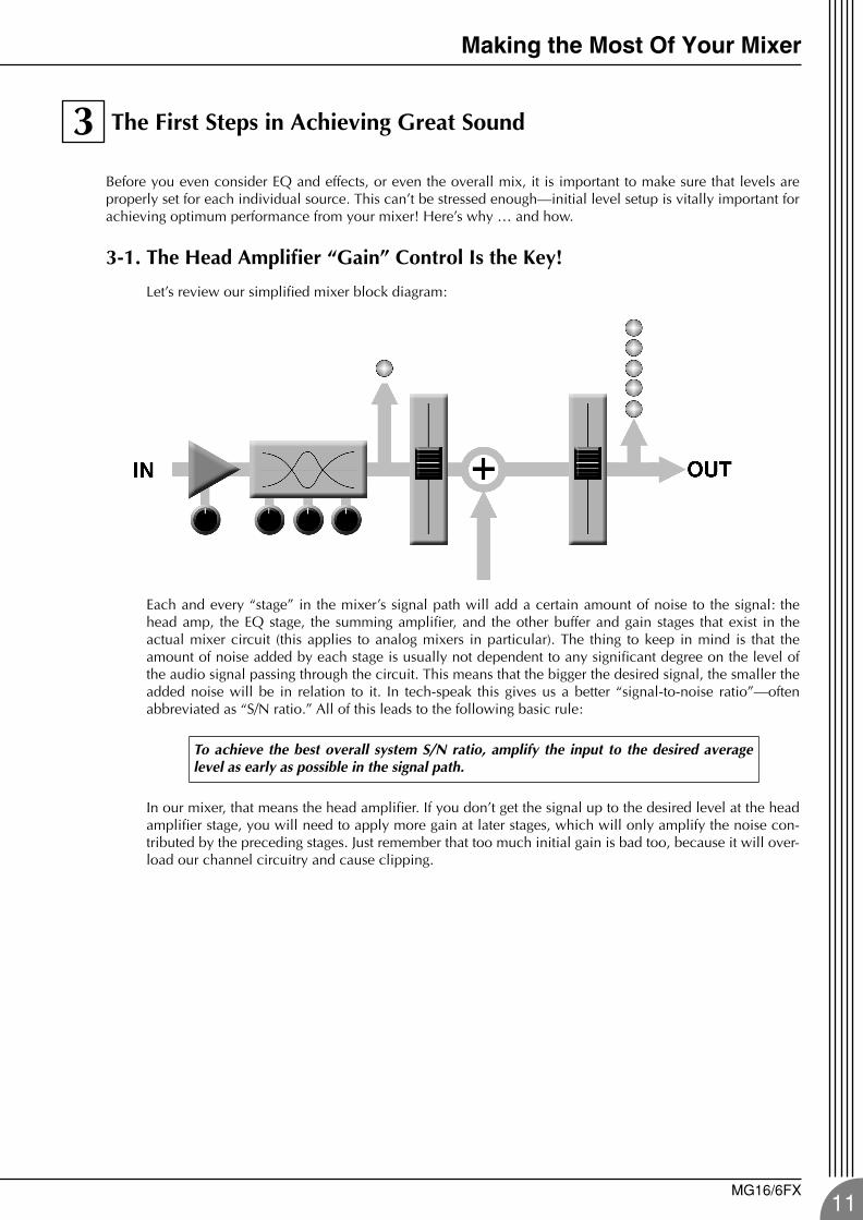
Let’s review our simplified mixer block diagram:
Each and every “stage” in the mixer’s signal path will add a certain amount of noise to the signal: thehead amp, the EQ stage, the summing amplifier, and the other buffer and gain stages that exist in theactual mixer circuit (this applies to analog mixers in particular). The thing to keep in mind is that theamount of noise added by each stage is usually not dependent to any significant degree on the level ofthe audio signal passing through the circuit. This means that the bigger the desired signal, the smaller theadded noise will be in relation to it. In tech-speak this gives us a better “signal-to-noise ratio”—oftenabbreviated as “S/N ratio.” All of this leads to the following basic rule:
In our mixer, that means the head amplifier. If you don’t get the signal up to the desired level at the headamplifier stage, you will need to apply more gain at later stages, which will only amplify the noise con-tributed by the preceding stages. Just remember that too much initial gain is bad too, because it will over-load our channel circuitry and cause clipping.
To achieve the best overall system S/N ratio, amplify the input to the desired averagelevel as early as possible in the signal path.
3
MG16/6FX11
Making the Most Of Your Mixer
12
MG16-6FX.book Page 12 Saturday, January 25, 2003 10:13 AM
3-2. Level Setup Procedure For Optimum Performance
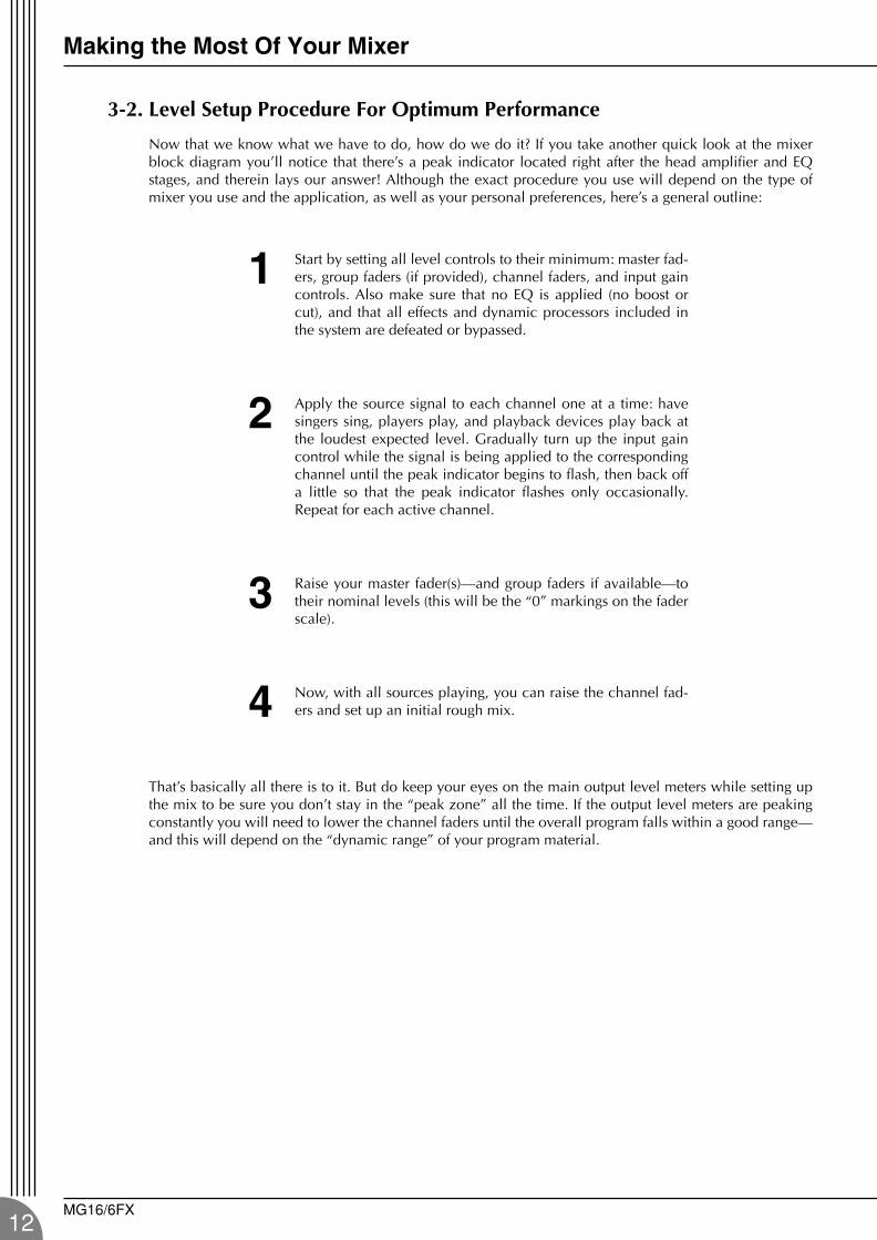
Now that we know what we have to do, how do we do it? If you take another quick look at the mixerblock diagram you’ll notice that there’s a peak indicator located right after the head amplifier and EQstages, and therein lays our answer! Although the exact procedure you use will depend on the type ofmixer you use and the application, as well as your personal preferences, here’s a general outline:
That’s basically all there is to it. But do keep your eyes on the main output level meters while setting upthe mix to be sure you don’t stay in the “peak zone” all the time. If the output level meters are peakingconstantly you will need to lower the channel faders until the overall program falls within a good range—and this will depend on the “dynamic range” of your program material.
1 Start by setting all level controls to their minimum: master fad-ers, group faders (if provided), channel faders, and input gaincontrols. Also make sure that no EQ is applied (no boost orcut), and that all effects and dynamic processors included inthe system are defeated or bypassed.
2 Apply the source signal to each channel one at a time: havesingers sing, players play, and playback devices play back atthe loudest expected level. Gradually turn up the input gaincontrol while the signal is being applied to the correspondingchannel until the peak indicator begins to flash, then back offa little so that the peak indicator flashes only occasionally.Repeat for each active channel.
3 Raise your master fader(s)—and group faders if available—totheir nominal levels (this will be the “0” markings on the faderscale).
4 Now, with all sources playing, you can raise the channel fad-ers and set up an initial rough mix.
MG16/6FX
Making the Most Of Your Mixer
MG16-6FX.book Page 13 Saturday, January 25, 2003 10:13 AM
External Effects, Monitor Mixes, and Groups
4-1. AUX Buses For Monitor Sends and Overall Effects
There are a number of reasons why you mightwant to “tap” the signal flowing through yourmixer at some point before the main outputs: thetwo most common being 1) to create a monitormix that is separate from the main mix, and 2) toprocess the signal via an external effect unit andthen bring it back into the mix. Both of these func-tions, and more, can be handled by the mixer’sAUX (Auxiliary) buses and level controls. If themixer has two AUX buses, then it can handle bothfunctions at the same time. Larger mixing con-soles can have 6, 8, or even more auxiliary busesto handle a variety of monitoring and processingneeds.
Using the AUX buses and level controls is prettystraightforward. The only thing you need to con-sider is whether you need a “pre-fader” or “post-fader” send. AUX sends often feature a switch thatallows you to configure them for pre- or post-fader operation.
Pre/Post—What’s the difference?
4
pre post
A “pre-fader” signal is takenfrom a point before thechannel fader, so the sendlevel is affected only by theAUX send level control andnot by the channel fader.
Pre-fader sends are mostcommonly used to providemonitor mixes.
A “post-fader” signal istaken from a point after thechannel fader, so its levelwill be affected by both theAUX send level control andthe channel fader.
Post-fader sends are mostcommonly used in conjunc-tion with the mixer’s AUX oreffect returns for externaleffect processing.
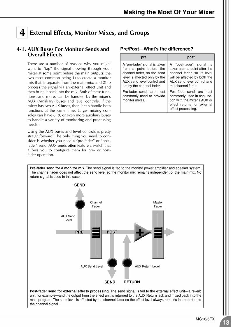
Pre-fader send for a monitor mix. The send signal is fed to the monitor power amplifier and speaker system.The channel fader does not affect the send level so the monitor mix remains independent of the main mix. Noreturn signal is used in this case.
Post-fader send for external effects processing. The send signal is fed to the external effect unit—a reverbunit, for example—and the output from the effect unit is returned to the AUX Return jack and mixed back into themain program. The send level is affected by the channel fader so the effect level always remains in proportion tothe channel signal.
Channel Fader
Master Fader
AUX Send Level
AUX Send Level AUX Return Level
MG16/6FX13
Making the Most Of Your Mixer
14
MG16-6FX.book Page 14 Saturday, January 25, 2003 10:13 AM
4-2. Using Groups
Group buses and faders can greatly simplify the mixing process—particularly in live situations in whichchanges have to be made as quickly as possible. If you have a group of channels that need to be adjustedall together while maintaining their relative levels, grouping is the way to go. Simply assign the group to agroup bus, and make sure that group is also assigned to the main program bus. Then you can adjust theoverall level of the group using a single group fader, rather than having to attempt to control multiplechannels faders simultaneously.
Group buses usually also have their own outputs, so you can send the group signal to a different externaldestination from the main mix.
Channel faders Assigned to Group(Controlled As a Group)
Stereo Master Fader
Group Fader
Channel faders Assigned to Stereo(Controlled Individually)
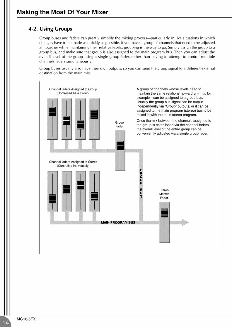
A group of channels whose levels need to maintain the same relationship—a drum mix, for example—can be assigned to a group bus. Usually the group bus signal can be output independently via “Group” outputs, or it can be assigned to the main program (stereo) bus to be mixed in with the main stereo program.
Once the mix between the channels assigned to the group is established via the channel faders, the overall level of the entire group can be conveniently adjusted via a single group fader.
MG16/6FX
Making the Most Of Your Mixer
MG16-6FX.book Page 15 Saturday, January 25, 2003 10:13 AM
4-3. Channel Inserts for Channel-specific Processing
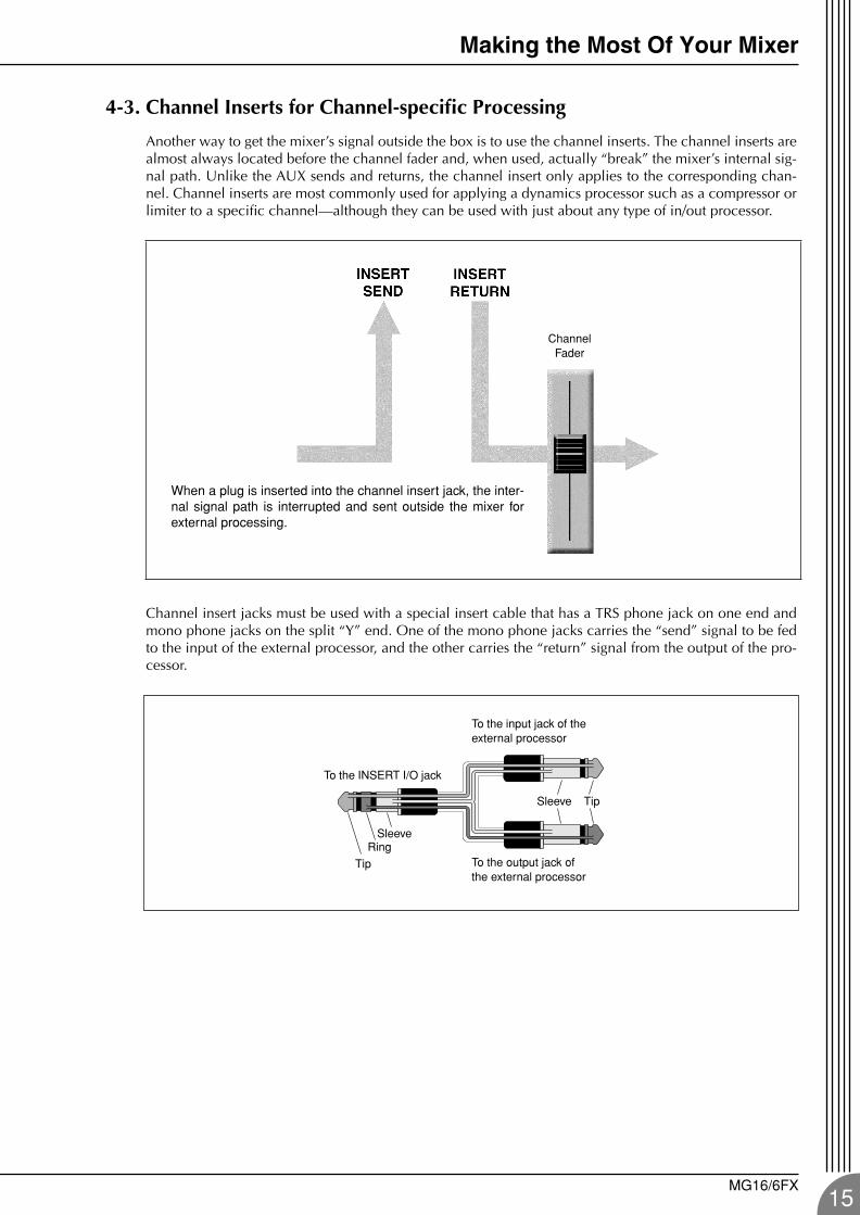
Another way to get the mixer’s signal outside the box is to use the channel inserts. The channel inserts arealmost always located before the channel fader and, when used, actually “break” the mixer’s internal sig-nal path. Unlike the AUX sends and returns, the channel insert only applies to the corresponding chan-nel. Channel inserts are most commonly used for applying a dynamics processor such as a compressor orlimiter to a specific channel—although they can be used with just about any type of in/out processor.
Channel insert jacks must be used with a special insert cable that has a TRS phone jack on one end andmono phone jacks on the split “Y” end. One of the mono phone jacks carries the “send” signal to be fedto the input of the external processor, and the other carries the “return” signal from the output of the pro-cessor.
Channel Fader
When a plug is inserted into the channel insert jack, the inter-nal signal path is interrupted and sent outside the mixer forexternal processing.
Tip
RingSleeve
To the INSERT I/O jack
To the input jack of the external processor
To the output jack of the external processor
TipSleeve
MG16/6FX15
Making the Most Of Your Mixer
16
MG16-6FX.book Page 16 Saturday, January 25, 2003 10:13 AM
Making Better Mixes
5-1. Approaching the Mix—Where Do You Start?
Mixing is easy, right? Just move the faders arounduntil it sounds right? Well, you can do it that way,but a more systematic approach that is suited tothe material you’re mixing will produce muchbetter results, and faster. There are no rules, andyou’ll probably end up developing a system thatworks best for you. But the key is to develop asystem rather than working haphazardly. Here area few ideas to get you started:
Faders DownIt might sound overly simple, but it is usually agood idea to start with all channel faders off—allthe way down. It’s also possible to start with allfaders at their nominal settings, but it’s too easy tolose perspective with this approach. Start with allfaders down, then bring them up one by one to fillout the mix. But which channel should you startwith?
Example1: Vocal Ballad Backed by Piano Trio What are you mixing? Is it a song in which thevocals are the most important element? If so youmight want to build the mix around the vocals.This means bringing the vocal channel up tonominal first (if your level setup procedure hasbeen done properly this will be a good startingpoint), and then adding the other instruments.What you add next will depend on the type ofmaterial you are working with and your approachto it. If the vocals are backed by a piano trio andthe song is a ballad, for example, you might wantto bring in the piano next and get the vocal/pianorelationship just right, then bring in the bass anddrums to support the overall sound.
Example2: Funky R&B Groove The approach will be totally different if you’remixing a funky R&B number that centers on thegroove. In this case most engineers will start withthe drums, and then add the bass. The relation-ship between the drums and bass is extremelyimportant to achieve the “drive” or groove themusic rides on. Pay particular attention to howthe bass works with the kick (bass drum). Theyshould almost sound like a single instrument—with the kick supplying the punch and the basssupplying the pitch. Once again, there are norules, but these are concepts that have beenproven to work well.
Music First—Then MixIn any case, the music comes first. Think aboutthe music and let it guide the mix, rather than try-ing to do things the other way around. What is themusic saying and what instrument or technique isbeing used to drive the message? That’s where thefocus of your mix should be. You’re using a high-tech tool to do the mixing, but the mix itself is asmuch art as the music. Approach it that way andyour mixes will become a vital part of the music.
5
MG16/6FX
Making the Most Of Your Mixer
MG16-6FX.book Page 17 Saturday, January 25, 2003 10:13 AM
5-2. Panning For Cleaner Mixes
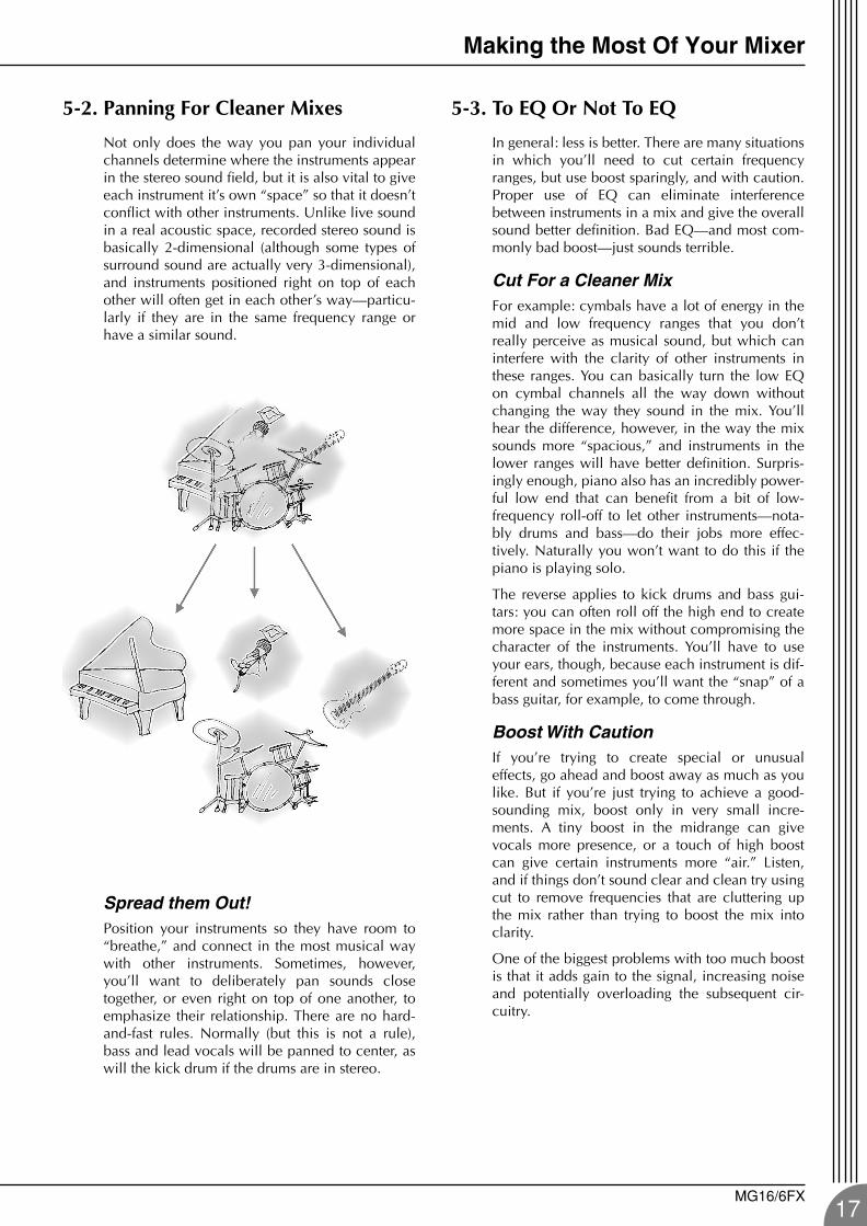
Not only does the way you pan your individualchannels determine where the instruments appearin the stereo sound field, but it is also vital to giveeach instrument it’s own “space” so that it doesn’tconflict with other instruments. Unlike live soundin a real acoustic space, recorded stereo sound isbasically 2-dimensional (although some types ofsurround sound are actually very 3-dimensional),and instruments positioned right on top of eachother will often get in each other’s way—particu-larly if they are in the same frequency range orhave a similar sound.
Spread them Out!Position your instruments so they have room to“breathe,” and connect in the most musical waywith other instruments. Sometimes, however,you’ll want to deliberately pan sounds closetogether, or even right on top of one another, toemphasize their relationship. There are no hard-and-fast rules. Normally (but this is not a rule),bass and lead vocals will be panned to center, aswill the kick drum if the drums are in stereo.
5-3. To EQ Or Not To EQ
In general: less is better. There are many situationsin which you’ll need to cut certain frequencyranges, but use boost sparingly, and with caution.Proper use of EQ can eliminate interferencebetween instruments in a mix and give the overallsound better definition. Bad EQ—and most com-monly bad boost—just sounds terrible.
Cut For a Cleaner MixFor example: cymbals have a lot of energy in themid and low frequency ranges that you don’treally perceive as musical sound, but which caninterfere with the clarity of other instruments inthese ranges. You can basically turn the low EQon cymbal channels all the way down withoutchanging the way they sound in the mix. You’llhear the difference, however, in the way the mixsounds more “spacious,” and instruments in thelower ranges will have better definition. Surpris-ingly enough, piano also has an incredibly power-ful low end that can benefit from a bit of low-frequency roll-off to let other instruments—nota-bly drums and bass—do their jobs more effec-tively. Naturally you won’t want to do this if thepiano is playing solo.
The reverse applies to kick drums and bass gui-tars: you can often roll off the high end to createmore space in the mix without compromising thecharacter of the instruments. You’ll have to useyour ears, though, because each instrument is dif-ferent and sometimes you’ll want the “snap” of abass guitar, for example, to come through.
Boost With CautionIf you’re trying to create special or unusualeffects, go ahead and boost away as much as youlike. But if you’re just trying to achieve a good-sounding mix, boost only in very small incre-ments. A tiny boost in the midrange can givevocals more presence, or a touch of high boostcan give certain instruments more “air.” Listen,and if things don’t sound clear and clean try usingcut to remove frequencies that are cluttering upthe mix rather than trying to boost the mix intoclarity.
One of the biggest problems with too much boostis that it adds gain to the signal, increasing noiseand potentially overloading the subsequent cir-cuitry.
MG16/6FX17
Making the Most Of Your Mixer
18
MG16-6FX.book Page 18 Saturday, January 25, 2003 10:13 AM
5-4. Ambience
Judicious application of reverb and/or delay viathe mixer’s AUX busses can really polish a mix,but too much can “wash out” the mix and reduceoverall clarity. The way you set up your reverbsound can make a huge difference in the way itmeshes with the mix.
Reverb/Delay TimeDifferent reverb/delay units offer different capabil-ities, but most offer some means of adjusting thereverb time. A little extra time spent matching thereverb time to the music being mixed can meanthe difference between great and merely averagesound. The reverb time you choose will dependto a great degree on the tempo and “density” ofthe mix at hand. Slower tempos and lower densi-ties (i.e. sparser mixes with less sonic activity) cansound good with relatively long reverb times. Butlong reverb times can completely wash out afaster more active piece of music. Similar princi-ples applies to delay.
Reverb ToneHow “bright” or “bassy” a reverb sound is alsohas a huge impact on the sound of your mix. Dif-ferent reverb units offer different means of con-trolling this—balance between the high- and low-frequency reverb times, simple EQ, and others. Areverb that is too bright will not only sound unnat-ural, but it will probably get in the way of delicatehighs you want to come through in your mix. Ifyou find yourself hearing more high-end reverbthan mix detail, try reducing the brightness of thereverb sound. This will allow you to get full-bod-ied ambience without compromising clarity.
Reverb LevelIt’s amazing how quickly your ears can lose per-spective and fool you into believing that a totallywashed-out mix sounds perfectly fine. To avoidfalling into this trap start with reverb level all theway down, then gradually bring the reverb intothe mix until you can just hear the difference. Anymore than this normally becomes a “specialeffect.” You don’t want reverb to dominate themix unless you are trying to create the effect of aband in a cave—which is a perfectly legitimatecreative goal if that’s the sort of thing you’re aim-ing for.
5-5. Built-in Effects & EQ
Your MG mixer features a high-performance inter-nal effect system and graphic equalizer that offersextraordinary sound-processing power and versa-tility without the need for external equipment.The internal DSP (Digital Signal Processor) letsyou individually add reverb and delay to eachchannel in the same way that you can with anexternal effect unit – but you don’t need to wireup any extra gear, and won’t suffer the signalquality loss that external connections sometimesentail. The graphic equalizer is ideal for shapingthe response of the overall mix, and for minimiz-ing feedback in live situations. For details seepage 22.
MG16/6FX
MG16-6FX.fm Page 19 Friday, June 27, 2003 4:08 PM
Front & Rear Panels
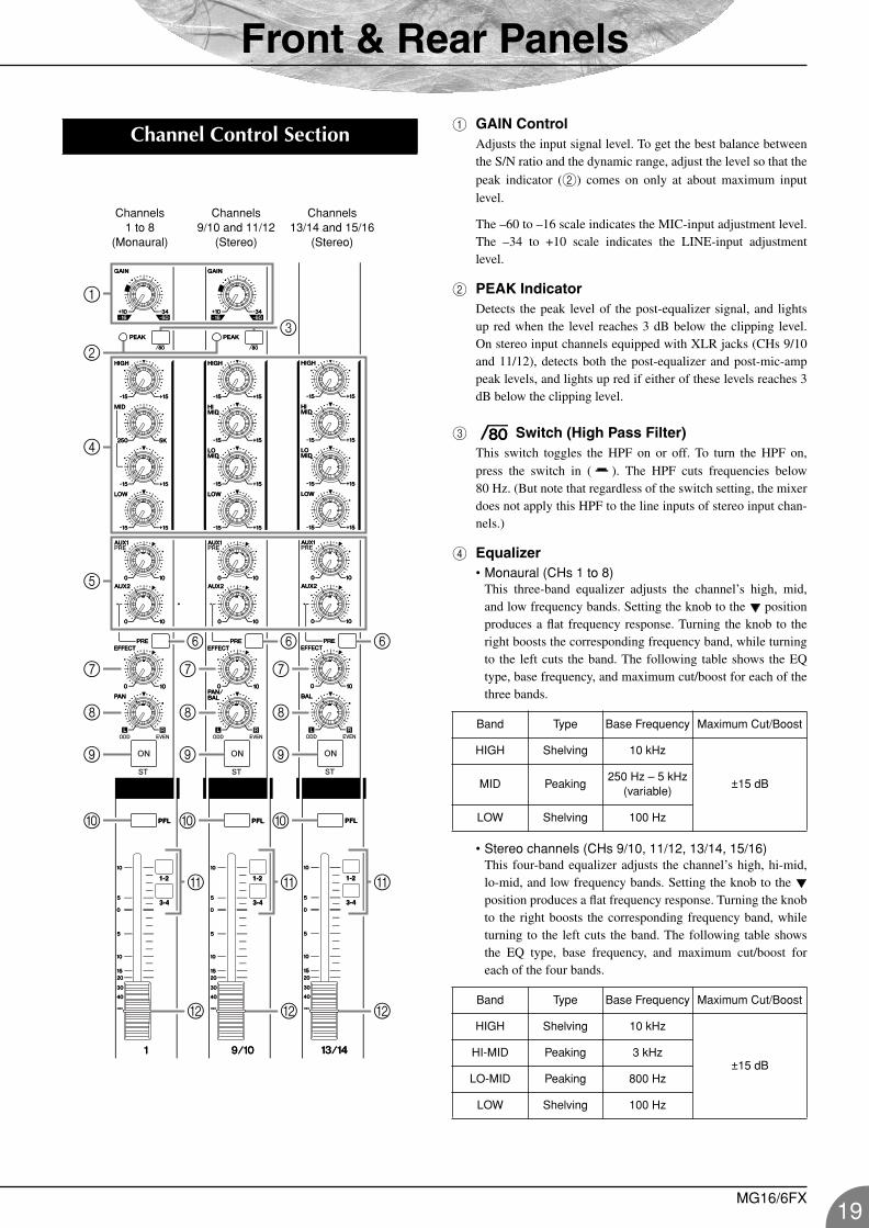
1 GAIN ControlAdjusts the input signal level. To get the best balance betweenthe S/N ratio and the dynamic range, adjust the level so that the
peak indicator (2) comes on only at about maximum inputlevel.
The –60 to –16 scale indicates the MIC-input adjustment level.The –34 to +10 scale indicates the LINE-input adjustmentlevel.
2 PEAK IndicatorDetects the peak level of the post-equalizer signal, and lightsup red when the level reaches 3 dB below the clipping level.On stereo input channels equipped with XLR jacks (CHs 9/10and 11/12), detects both the post-equalizer and post-mic-amppeak levels, and lights up red if either of these levels reaches 3dB below the clipping level.
3 Switch (High Pass Filter)This switch toggles the HPF on or off. To turn the HPF on,press the switch in ( ). The HPF cuts frequencies below80 Hz. (But note that regardless of the switch setting, the mixerdoes not apply this HPF to the line inputs of stereo input chan-nels.)
4 Equalizer• Monaural (CHs 1 to 8)
This three-band equalizer adjusts the channel’s high, mid,and low frequency bands. Setting the knob to the positionproduces a flat frequency response. Turning the knob to theright boosts the corresponding frequency band, while turningto the left cuts the band. The following table shows the EQtype, base frequency, and maximum cut/boost for each of thethree bands.
• Stereo channels (CHs 9/10, 11/12, 13/14, 15/16)This four-band equalizer adjusts the channel’s high, hi-mid,lo-mid, and low frequency bands. Setting the knob to the position produces a flat frequency response. Turning the knobto the right boosts the corresponding frequency band, whileturning to the left cuts the band. The following table showsthe EQ type, base frequency, and maximum cut/boost foreach of the four bands.
Channel Control Section
6
3
B
0 0 0
9
8
7
9
8
7
9
8
7
5
1
4
A
B
A
B
A
2
66
Channels 1 to 8
(Monaural)
Channels 9/10 and 11/12
(Stereo)
Channels 13/14 and 15/16
(Stereo)
Band Type Base Frequency Maximum Cut/Boost
HIGH Shelving 10 kHz
±15 dBMID Peaking250 Hz – 5 kHz
(variable)
LOW Shelving 100 Hz
Band Type Base Frequency Maximum Cut/Boost
HIGH Shelving 10 kHz
±15 dBHI-MID Peaking 3 kHz
LO-MID Peaking 800 Hz
LOW Shelving 100 Hz
MG16/6FX19
Front & Rear Panels
20
MG16-6FX.book Page 20 Saturday, January 25, 2003 10:13 AM
5 AUX1 and AUX2 ControlsThe AUX1 knob controls the signal level that the channel sendsto the AUX1 bus; the AUX2 knob controls the signal level tothe AUX2 bus. These knobs should generally be set close to the
position.
If you are using stereo channels, the signals from the L (odd)and R (even) channels are mixed and sent to the AUX1 andAUX2 buses.
These controls allow you to output the signal to theAUX buses regardless of the setting of the STswitch 9.
6 PRE SwitchSelects whether the pre-fader or the post-fader signal is fed tothe AUX2 bus. If you set the switch on ( ), the mixer sendsthe pre-fader signal—the signal prior to passage though chan-nel fader B—to the AUX2 bus, so that AUX2 output is notaffected by the fader. If you set the switch off ( ) the mixersends the post-fader signal to the AUX2 bus.
Note that this switch applies to AUX2 only. The signal to theAUX1 bus always passes through the channel fader first.
7 EFFECT ControlAdjusts the level of the signal sent from the channel to theEFFECT bus. Note that the signal level will also vary accord-ing to the setting of the channel fader.
If you are using stereo channels (CHs 9/10, 11/12, 13/14,15/16), the signals from the L (odd) and R (even) channels aremixed and then sent to the EFFECT bus.
8 PAN Control (CHs 1 to 8) PAN/BAL Control (9/10 and 11/12) BAL Control (13/14 and 15/16)The PAN control determines the positioning of the channel’ssignal on the Group 1-2/3-4 buses or on the Stereo L and Rbuses.
The BAL control knob sets the balance between left and rightchannels. Signals into to the L input (odd channel) feed to theGroup 1/3 bus or to the Stereo L bus; signals into the R input(even channel) feed to the Group 2/4 bus or the Stereo R bus.
On channels where this knob provides both PANand BAL controls (9/10 and 11/12), the knob oper-ates as a PAN control if you are inputting throughthe MIC jack or into the L (MONO) input only, andoperates as a BAL control if you are inputting intoboth L and R inputs.
9 ST Switch
This switch assigns the channel’s signal to the Stereo L and Rbuses. To send the signal to the Stereo bus, set the switch on bypressing it in ( ). The switch lights up orange to indicate thatit is on.
0 PFL (Pre-Fader Listen) SwitchThis switch lets you monitor the channel’s pre-fader signal. Toset the switch on, press it in ( ) so that it lights up. When theswitch is on, the mixer outputs the channel’s pre-fader signal tothe PHONES and C-R OUT jacks, for monitoring.
A GROUP SwitchesUse these switches to send the channel's signal to the Group1-2 and/or Group 3-4 buses. Setting the switch on ( ) causesthe signal to be sent to the corresponding group buses.
These switches allow you to assign the signal toeither or both groups regardless of the setting of theST switch 9.
B Channel Fader Adjusts the output level of the signal being input to the chan-nel. Use these faders to adjust the volume balance among thevarious channels.
To reduce noise, set the fader sliders for unusedchannels all the way down.
NOTE
NOTE
NOTE
NOTE
MG16/6FX
Front & Rear Panels
MG16-6FX.fm Page 21 Thursday, December 11, 2003 9:15 AM
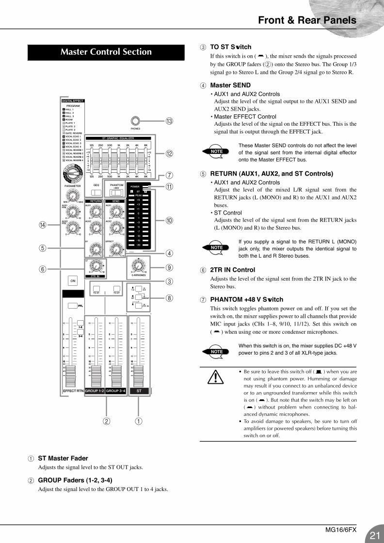
1 ST Master FaderAdjusts the signal level to the ST OUT jacks.
2 GROUP Faders (1-2, 3-4)Adjust the signal level to the GROUP OUT 1 to 4 jacks.
3 TO ST SwitchIf this switch is on ( ), the mixer sends the signals processed
by the GROUP faders (2) onto the Stereo bus. The Group 1/3signal go to Stereo L and the Group 2/4 signal go to Stereo R.
4 Master SEND • AUX1 and AUX2 Controls
Adjust the level of the signal output to the AUX1 SEND andAUX2 SEND jacks.
• Master EFFECT ControlAdjusts the level of the signal on the EFFECT bus. This is thesignal that is output through the EFFECT jack.
These Master SEND controls do not affect the levelof the signal sent from the internal digital effectoronto the Master EFFECT bus.
5 RETURN (AUX1, AUX2, and ST Controls)• AUX1 and AUX2 Controls
Adjust the level of the mixed L/R signal sent from theRETURN jacks (L (MONO) and R) to the AUX1 and AUX2buses.
• ST ControlAdjusts the level of the signal sent from the RETURN jacks(L (MONO) and R) to the Stereo bus.
If you supply a signal to the RETURN L (MONO)jack only, the mixer outputs the identical signal toboth the L and R Stereo buses.
6 2TR IN ControlAdjusts the level of the signal sent from the 2TR IN jack to theStereo bus.
7 PHANTOM +48 V SwitchThis switch toggles phantom power on and off. If you set theswitch on, the mixer supplies power to all channels that provideMIC input jacks (CHs 1–8, 9/10, 11/12). Set this switch on( ) when using one or more condenser microphones.
When this switch is on, the mixer supplies DC +48 Vpower to pins 2 and 3 of all XLR-type jacks.
• Be sure to leave this switch off ( ) when you arenot using phantom power. Humming or damagemay result if you connect to an unbalanced deviceor to an ungrounded transformer while this switchis on ( ). But note that the switch may be left on( ) without problem when connecting to bal-anced dynamic microphones.
• To avoid damage to speakers, be sure to turn offamplifiers (or powered speakers) before turning thisswitch on or off.
Master Control Section
C
0
9
5
D
6
7
8
3
2 1
4
B
A
NOTE
NOTE
NOTE
MG16/6FX21
Front & Rear Panels
22
MG16-6FX.book Page 22 Saturday, January 25, 2003 10:13 AM
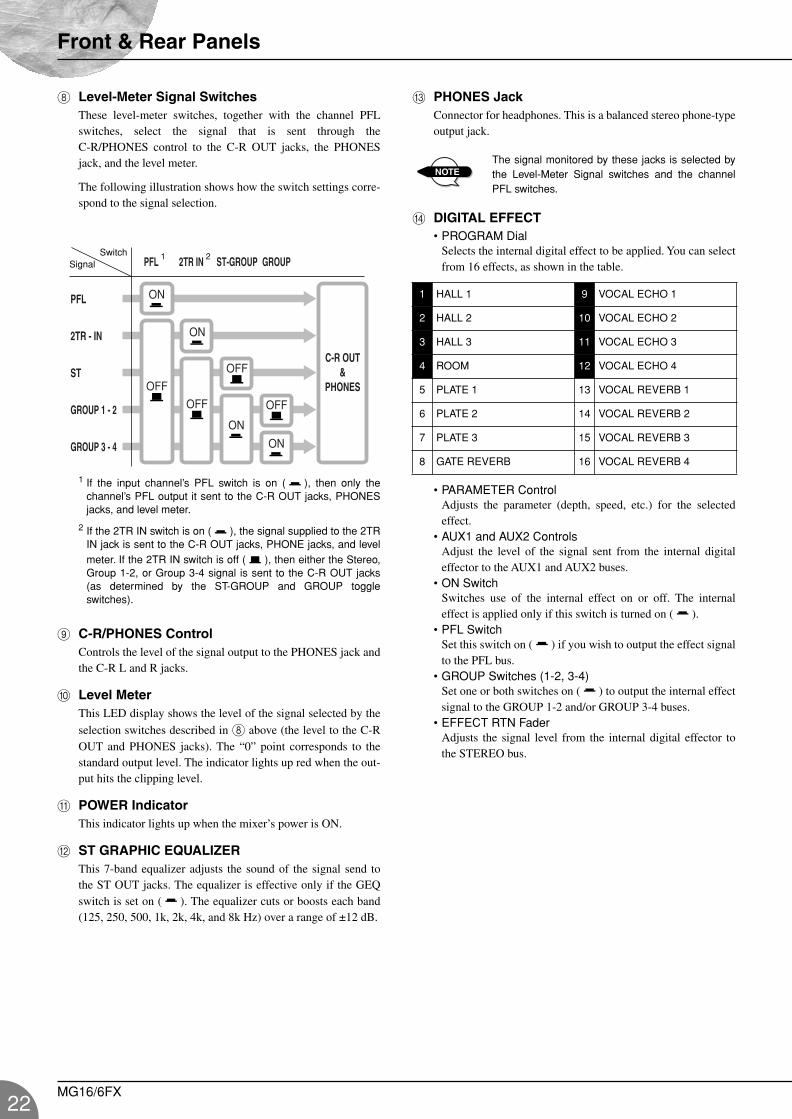
8 Level-Meter Signal Switches These level-meter switches, together with the channel PFLswitches, select the signal that is sent through theC-R/PHONES control to the C-R OUT jacks, the PHONESjack, and the level meter.
The following illustration shows how the switch settings corre-spond to the signal selection.
1 If the input channel’s PFL switch is on ( ), then only thechannel’s PFL output it sent to the C-R OUT jacks, PHONESjacks, and level meter.
2 If the 2TR IN switch is on ( ), the signal supplied to the 2TRIN jack is sent to the C-R OUT jacks, PHONE jacks, and levelmeter. If the 2TR IN switch is off ( ), then either the Stereo,Group 1-2, or Group 3-4 signal is sent to the C-R OUT jacks(as determined by the ST-GROUP and GROUP toggleswitches).
9 C-R/PHONES ControlControls the level of the signal output to the PHONES jack andthe C-R L and R jacks.
0 Level MeterThis LED display shows the level of the signal selected by the
selection switches described in 8 above (the level to the C-ROUT and PHONES jacks). The “0” point corresponds to thestandard output level. The indicator lights up red when the out-put hits the clipping level.
A POWER IndicatorThis indicator lights up when the mixer’s power is ON.
B ST GRAPHIC EQUALIZERThis 7-band equalizer adjusts the sound of the signal send tothe ST OUT jacks. The equalizer is effective only if the GEQswitch is set on ( ). The equalizer cuts or boosts each band(125, 250, 500, 1k, 2k, 4k, and 8k Hz) over a range of ±12 dB.
C PHONES JackConnector for headphones. This is a balanced stereo phone-typeoutput jack.
The signal monitored by these jacks is selected bythe Level-Meter Signal switches and the channelPFL switches.
D DIGITAL EFFECT• PROGRAM Dial
Selects the internal digital effect to be applied. You can selectfrom 16 effects, as shown in the table.
• PARAMETER ControlAdjusts the parameter (depth, speed, etc.) for the selectedeffect.
• AUX1 and AUX2 ControlsAdjust the level of the signal sent from the internal digitaleffector to the AUX1 and AUX2 buses.
• ON SwitchSwitches use of the internal effect on or off. The internaleffect is applied only if this switch is turned on ( ).
• PFL SwitchSet this switch on ( ) if you wish to output the effect signalto the PFL bus.
• GROUP Switches (1-2, 3-4)Set one or both switches on ( ) to output the internal effectsignal to the GROUP 1-2 and/or GROUP 3-4 buses.
• EFFECT RTN FaderAdjusts the signal level from the internal digital effector tothe STEREO bus.
2TR - IN
2TR IN
PFL
PFL
ST
GROUP 3 - 4
ST-GROUP GROUP
GROUP 1 - 2
ON
OFF
ON
ON
ON
OFF
OFF
OFF
C-R OUT&
PHONES
SwitchSignal
1 2
1 HALL 1 9 VOCAL ECHO 1
2 HALL 2 10 VOCAL ECHO 2
3 HALL 3 11 VOCAL ECHO 3
4 ROOM 12 VOCAL ECHO 4
5 PLATE 1 13 VOCAL REVERB 1
6 PLATE 2 14 VOCAL REVERB 2
7 PLATE 3 15 VOCAL REVERB 3
8 GATE REVERB 16 VOCAL REVERB 4
NOTE
MG16/6FX
Front & Rear Panels
MG16-6FX.fm Page 23 Wednesday, January 29, 2003 6:04 PM
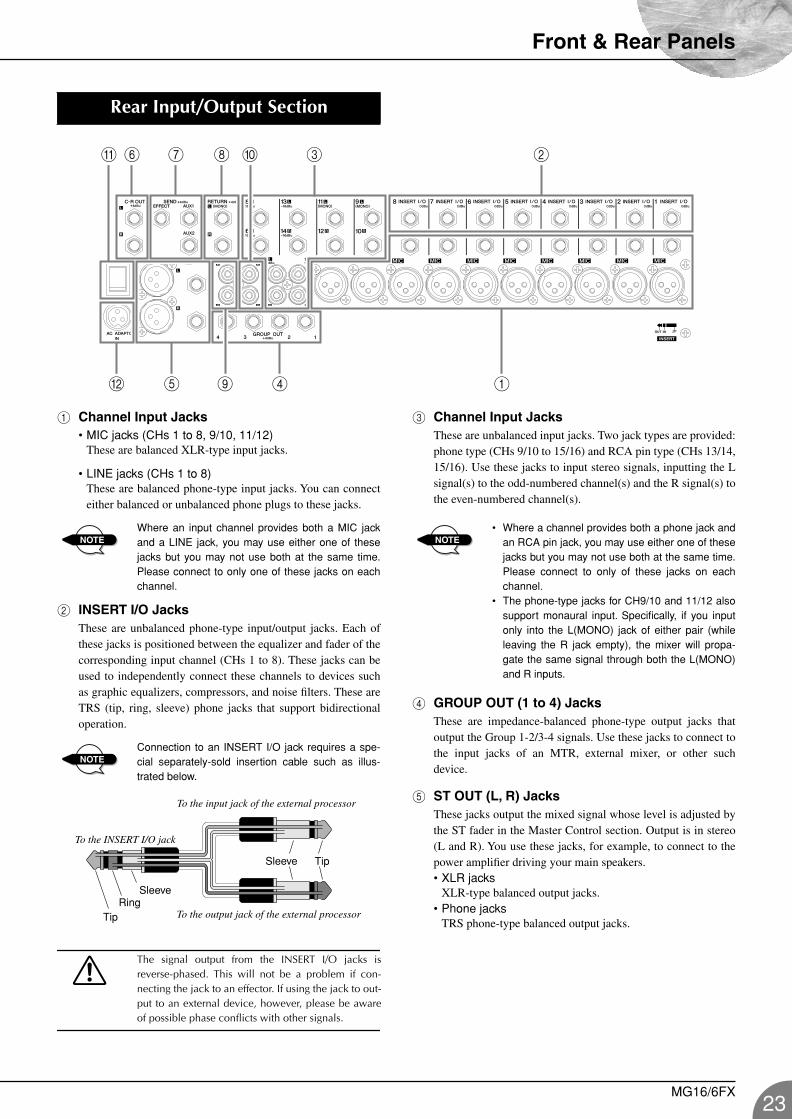
1 Channel Input Jacks• MIC jacks (CHs 1 to 8, 9/10, 11/12)
These are balanced XLR-type input jacks.
• LINE jacks (CHs 1 to 8)These are balanced phone-type input jacks. You can connecteither balanced or unbalanced phone plugs to these jacks.
Where an input channel provides both a MIC jackand a LINE jack, you may use either one of thesejacks but you may not use both at the same time.Please connect to only one of these jacks on eachchannel.
2 INSERT I/O JacksThese are unbalanced phone-type input/output jacks. Each ofthese jacks is positioned between the equalizer and fader of thecorresponding input channel (CHs 1 to 8). These jacks can beused to independently connect these channels to devices suchas graphic equalizers, compressors, and noise filters. These areTRS (tip, ring, sleeve) phone jacks that support bidirectionaloperation.
Connection to an INSERT I/O jack requires a spe-cial separately-sold insertion cable such as illus-trated below.
The signal output from the INSERT I/O jacks isreverse-phased. This will not be a problem if con-necting the jack to an effector. If using the jack to out-put to an external device, however, please be awareof possible phase conflicts with other signals.
3 Channel Input JacksThese are unbalanced input jacks. Two jack types are provided:phone type (CHs 9/10 to 15/16) and RCA pin type (CHs 13/14,15/16). Use these jacks to input stereo signals, inputting the Lsignal(s) to the odd-numbered channel(s) and the R signal(s) tothe even-numbered channel(s).
• Where a channel provides both a phone jack andan RCA pin jack, you may use either one of thesejacks but you may not use both at the same time.Please connect to only of these jacks on eachchannel.
• The phone-type jacks for CH9/10 and 11/12 alsosupport monaural input. Specifically, if you inputonly into the L(MONO) jack of either pair (whileleaving the R jack empty), the mixer will propa-gate the same signal through both the L(MONO)and R inputs.
4 GROUP OUT (1 to 4) JacksThese are impedance-balanced phone-type output jacks thatoutput the Group 1-2/3-4 signals. Use these jacks to connect tothe input jacks of an MTR, external mixer, or other suchdevice.
5 ST OUT (L, R) JacksThese jacks output the mixed signal whose level is adjusted bythe ST fader in the Master Control section. Output is in stereo(L and R). You use these jacks, for example, to connect to thepower amplifier driving your main speakers.• XLR jacks
XLR-type balanced output jacks.• Phone jacks
TRS phone-type balanced output jacks.
Rear Input/Output Section
4 15B
6A 37 8 2
9
0
NOTE
NOTE
To the INSERT I/O jack
To the input jack of the external processor
To the output jack of the external processor Ring
Sleeve
Tip
Sleeve Tip
NOTE
MG16/6FX23
Front & Rear Panels
24
MG16-6FX.fm Page 24 Wednesday, January 29, 2003 6:04 PM
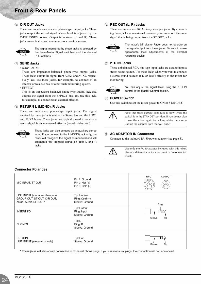
6 C-R OUT JacksThese are impedance-balanced phone-type output jacks. Thesejacks output the mixed signal whose level is adjusted by theC-R/PHONES control. Output is in stereo (L and R). Thesejacks are typically used to connect to a monitor system.
The signal monitored by these jacks is selected bythe Level-Meter Signal switches and the channelPFL switches.
7 SEND Jacks• AUX1, AUX2
These are impedance-balanced phone-type output jacks.These jacks output the signal from AUX1 and AUX2, respec-tively. You use these jacks, for example, to connect to aneffector or to a cue box or other such monitoring system.
• EFFECTThis is an impedance-balanced phone-type output jack thatoutputs the signal from the EFFECT bus. You use this jack,for example, to connect to an external effector.
8 RETURN L (MONO), R JacksThese are unbalanced phone-type input jacks. The signalreceived by these jacks is sent to the Stereo bus and the AUX1and AUX2 buses. These jacks are typically used to receive areturn signal from an external effector (reverb, delay, etc.).
These jacks can also be used as an auxiliary stereoinput. If you connect to the L(MONO) jack only, themixer will recognize the signal as monaural and willpropagate the identical signal on both L and Rjacks.
9 REC OUT (L, R) JacksThese are unbalanced RCA-pin-type output jacks. By connect-ing these jacks to an external recorder, you can record the samesignal that is being output from the ST OUT jacks.
The mixer’s ST Master Fader does not operate onthe signal output from these jacks. Be sure to makeappropriate level adjustments at the externalrecording device.
0 2TR IN JacksThese unbalanced RCA-pin-type input jacks are used to input astereo sound source. Use these jacks when you want to connecta stereo sound sources (CD or DAT) directly to the mixer formonitoring.
You can adjust the signal level using the 2TR INcontrol in the Master Control section.
A POWER SwitchUse this switch to set the mixer power to ON or STANDBY.
Note that trace current continues to flow while theswitch is in the STANDBY position. If you do not planto use the mixer again for a long while, be sure tounplug the adaptor from the wall outlet.
B AC ADAPTOR IN ConnectorConnects to the included PA-30 power adaptor (see page 5).
Use only the PA-30 adaptor included with this mixer.Use of a different adaptor may result in fire or electricshock.
Connector Polarities
* These jacks will also accept connection to monaural phone plugs. If you use monaural plugs, the connection will be unbalanced.
NOTE
NOTE
NOTE
NOTE
MIC INPUT, ST OUTPin 1: GroundPin 2: Hot (+)Pin 3: Cold (–)
LINE INPUT (monaural channels),GROUP OUT, ST OUT, C-R OUT,AUX1, AUX2, EFFECT*
Tip: Hot (+)Ring: Cold (–)Sleeve: Ground
INSERT I/OTip: OutputRing: InputSleeve: Ground
PHONESTip: LRing: RSleeve: Ground
RETURN,LINE INPUT (stereo channels)
Tip: HotSleeve: Ground
INPUT OUTPUT
Ring
Sleeve Tip
Sleeve Tip
MG16/6FX
MG16-6FX.book Page 25 Saturday, January 25, 2003 10:13 AM
Setting Up
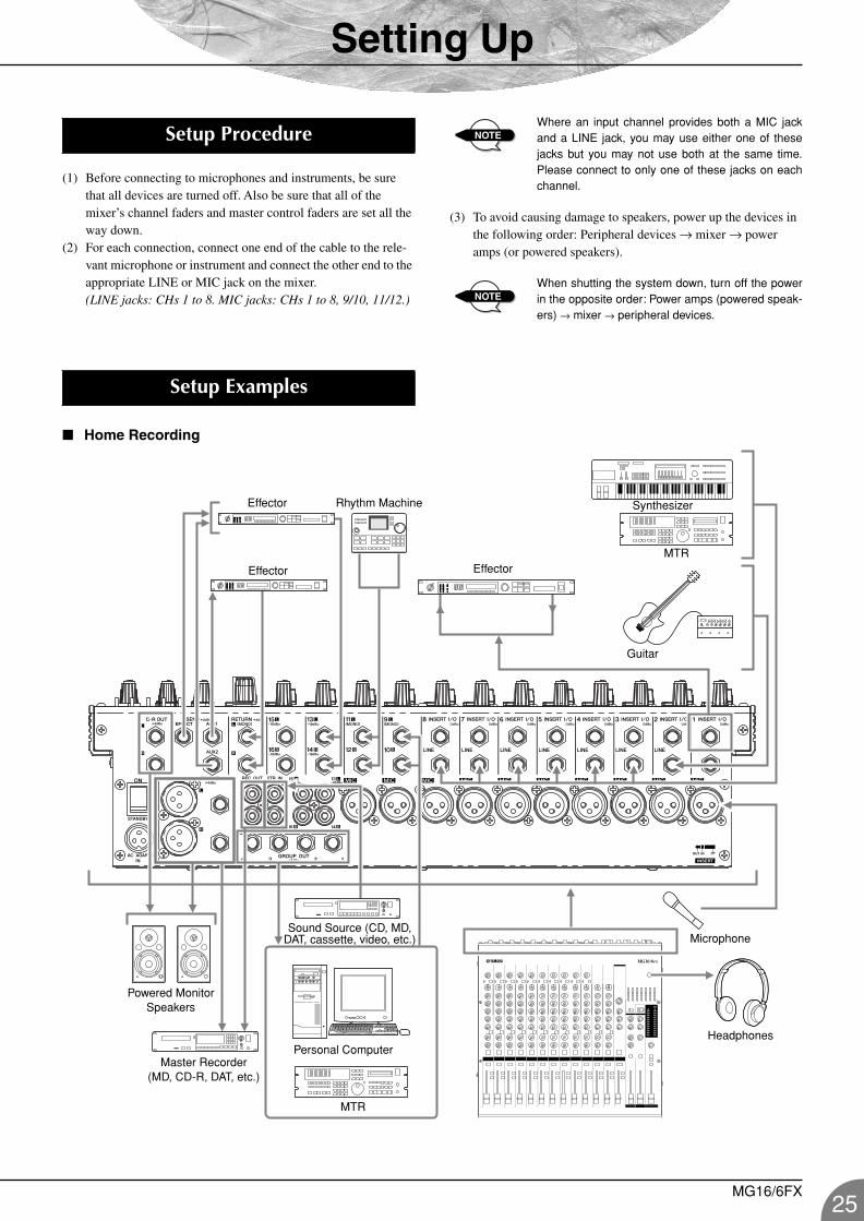
(1) Before connecting to microphones and instruments, be sure that all devices are turned off. Also be sure that all of the mixer’s channel faders and master control faders are set all the way down.
(2) For each connection, connect one end of the cable to the rele-vant microphone or instrument and connect the other end to the appropriate LINE or MIC jack on the mixer. (LINE jacks: CHs 1 to 8. MIC jacks: CHs 1 to 8, 9/10, 11/12.)
Where an input channel provides both a MIC jackand a LINE jack, you may use either one of thesejacks but you may not use both at the same time.Please connect to only one of these jacks on eachchannel.
(3) To avoid causing damage to speakers, power up the devices in the following order: Peripheral devices → mixer → power amps (or powered speakers).
When shutting the system down, turn off the powerin the opposite order: Power amps (powered speak-ers) → mixer → peripheral devices.
Home Recording
Setup Procedure NOTE
NOTE
Setup Examples
Rhythm Machine
Effector
Effector
Effector
Synthesizer
MTR
Guitar
Powered Monitor Speakers
Master Recorder(MD, CD-R, DAT, etc.)
Sound Source (CD, MD, DAT, cassette, video, etc.)
MTR
Microphone
HeadphonesPersonal Computer
MG16/6FX25
Setting Up
26
MG16-6FX.book Page 26 Saturday, January 25, 2003 10:13 AM
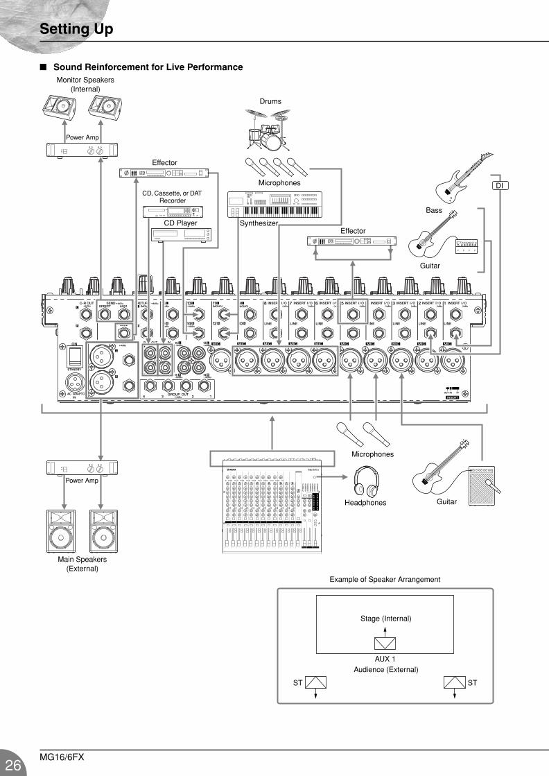
Sound Reinforcement for Live Performance
ST
AUX 1
ST
DIMicrophones
Monitor Speakers(Internal)
Power Amp
Effector
SynthesizerEffector
Bass
Guitar
CD, Cassette, or DAT Recorder
Microphones
Headphones Guitar
Main Speakers(External)
Example of Speaker Arrangement
Audience (External)
Stage (Internal)
Drums
CD Player
Power Amp
MG16/6FX
Setting Up
MG16-6FX.book Page 27 Saturday, January 25, 2003 10:13 AM
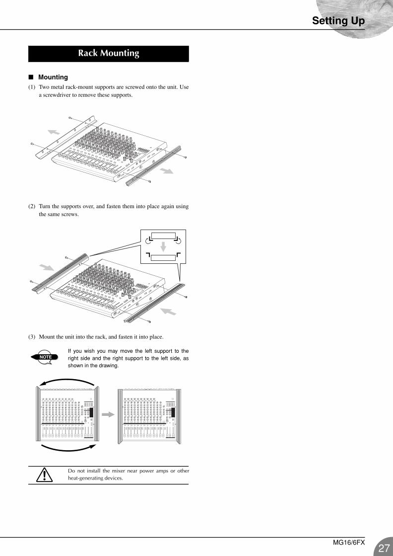
Mounting(1) Two metal rack-mount supports are screwed onto the unit. Use
a screwdriver to remove these supports.
(2) Turn the supports over, and fasten them into place again usingthe same screws.
(3) Mount the unit into the rack, and fasten it into place.
If you wish you may move the left support to theright side and the right support to the left side, asshown in the drawing.
Do not install the mixer near power amps or otherheat-generating devices.
Rack Mounting
NOTE
MG16/6FX27
28
MG16-6FX.fm Page 28 Friday, June 27, 2003 4:09 PM
Appendix
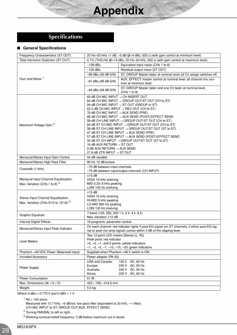
General Specifications
Where 0 dBu = 0.775 V and 0 dBV = 1 V
1 Rs = 150 ohms Measured with 12.7 kHz, –6 dB/oct. low pass filter (equivalent to 20 kHz, –∞ filter). (CH MIC INPUT to ST, GROUP OUT/AUX, EFFECT SEND)
2 Turning PAN/BAL to left or right.3 Shelving turnover/rolloff frequency: 3 dB before maximum cut or boost.
Specifications
Frequency Characteristics (ST OUT) 20 Hz–20 kHz +1 dB, –3 dB @+4 dBu, 600 Ω (with gain control at minimum level)
Total Harmonic Distortion (ST OUT) 0.1% (THD+N) @+14 dBu, 20 Hz–20 kHz, 600 Ω (with gain control at maximum level)
Hum and Noise 1
–128 dBu Equivalent input noise (CHs 1 to 8)
–100 dBu Residual output noise (ST OUT)
–88 dBu (92 dB S/N) ST, GROUP Master fader at nominal level; all Ch assign switches off.
–81 dBu (85 dB S/N)AUX, EFFECT master control at nominal level; all channel mix con-trols at minimum level.
–64 dBu (68 dB S/N)ST, GROUP Master fader and one Ch fader at nominal level. (CHs 1 to 8)
Maximum Voltage Gain 2
60 dB CH MIC INPUT → CH INSERT OUT84 dB CH MIC INPUT → GROUP OUT/ST OUT (CH to ST)94 dB CH MIC INPUT → ST OUT (GROUP to ST)62.2 dB CH MIC INPUT → REC OUT (CH to ST)76 dB CH MIC INPUT → AUX SEND (PRE)86 dB CH MIC INPUT → AUX SEND (POST)/EFFECT SEND58 dB CH LINE INPUT → GROUP OUT/ST OUT (CH to ST)84 dB ST CH MIC INPUT → GROUP OUT/ST OUT (CH to ST)58 dB ST CH LINE INPUT → GROUP OUT/ST OUT (ST to ST)47 dB ST CH LINE INPUT → AUX SEND (PRE)57 dB ST CH LINE INPUT → AUX SEND (POST)/EFFECT SEND34 dB ST CH INPUT → GROUP OUT/ST OUT (ST to ST)16 dB AUX RETURN → ST OUT9 dB AUX RETURN → AUX SEND27.8 dB 2TR INPUT → ST OUT
Monaural/Stereo Input Gain Control 44 dB variable
Monaural/Stereo High Pass Filter 80 Hz 12 dB/octave
Crosstalk (1 kHz)–70 dB between input channels–70 dB between input/output channels (CH INPUT)
Monaural Input Channel Equalization:
Max. Variation (CHs 1 to 8) 3
±15 dBHIGH 10 kHz shelvingMID 0.25–5 kHz peakingLOW 100 Hz shelving
Stereo Input Channel Equalization:
Max. Variation (CHs 9/10 to 15/16) 3
±15 dBHIGH 10 kHz shelvingHI-MID 3 kHz peakingLO-MID 800 Hz peakingLOW 100 Hz shelving
Graphic Equalizer7-band (125, 250, 500 1 k, 2 k, 4 k, 8 k)Max. Variation ±12 dB
Internal Digital Effects 16 programs, parameter control
Monaural/Stereo Input Peak IndicatorOn each channel: red indicator lights if post-EQ signal (on ST channels, if either post-EQ sig-nal or post-mic-amp signal) comes within 3 dB of the clipping level.
Level Meters
Two 12-point LED meters [Stereo (L, R)]Peak point: red indicator+5, +3, +1, and 0 points: yellow indicators–1, –3, –5, –7, –10, –15, –20: green indicators
Phantom +48 VDC Power (Balanced input) Supplied when Phantom +48 V switch is ON.
Included Accessory Power adaptor (PA-30)
Power Supply
USA and Canada: 120 V AC, 60 HzEurope: 230 V AC, 50 HzAustralia: 240 V AC, 50 HzKorea: 220 V AC, 60 Hz
Power Consumption 51 W
Max. Dimensions (W × H × D) 423 × 108 × 416.6 mm
Weight 5.5 kg
MG16/6FX

Appendix
MG16-6FX.fm Page 29 Friday, June 27, 2003 4:09 PM
Input Specifications
Where 0 dBu = 0.775 V and 0 dBV= 1 V* Input sensitivity: the lowest level that will produce the nominal output level when the unit is set to maximum gain.
Output Specifications
Where 0 dBu = 0.775 V and 0 dBV= 1 V
Specifications and descriptions in this owner’s manual are for information purposes only. Yamaha Corp. reserves the right to change or modifyproducts or specifications at any time without prior notice. Since specifications, equipment or options may not be the same in every locale,please check with your Yamaha dealer.
European ModelsPurchaser/User Information specified in EN55103-1 and EN55103-2.Inrush Current: 6AConforms to Environments: E1, E2, E3 and E4
Input Connector Gain Input Impedance
Appropriate Impedance Sensitivity* Rated Level Max. Before
ClippingConnector
Specifications
MIC INPUT(CHs 1 to 8)
–60
3 kΩ 50–600 Ω mic
–80 dBu (0.078 mV)
–60 dBu (0.775 mV)
–40 dBu (7.75 mV)
XLR-3-31 type (balanced)
–16 –36 dBu (12.3 mV)
–16 dBu (123 mV)
+4 dBu (1.23 V)
LINE INPUT(CHs 1 to 8)
–34
10 kΩ 600 Ω line
–54 dBu (1.55 mV)
–34 dBu (15.5 mV)
–14 dBu (155 mV) Phone jack (TRS)
(balanced [T: hot; R: cold; S: ground])
+10 –10 dBu (245 mV)
+10 dBu (2.45 V)
+30 dBu (24.5 V)
ST CH MIC INPUT(CH9(L)/CH10(R), CH11(L)/CH12(R))
–60
3 kΩ 50–600 Ω mic
–80 dBu (0.078 mV)
–60 dBu (0.775 mV)
–40 dBu (7.75 mV)
XLR-3-31 type (balanced)
–16 –36 dBu (12.3 mV)
–16 dBu (123 mV)
–10 dBu (245 mV)
ST CH LINE INPUT(CH9(L)/CH10(R), CH11(L)/CH12(R))
–34
10 kΩ 600 Ω line
–54 dBu (1.55 mV)
–34 dBu (15.5 mV)
–14 dBu (155 mV)
Phone jack (unbalanced)
+10 –10 dBu (245 mV)
+10 dBu (2.45 V)
+30 dBu (24.5 V)
ST CH INPUT(CH13(L)/CH14(R), CH15(L)/CH16(R))
10 kΩ 600 Ω line –30 dBu (24.5 mV)
–10 dBu (245 mV)
+10 dBu (2.45 V)
Phone jack (unbalanced);RCA pin jack
CH INSERT IN (CHs 1 to 8) 10 kΩ 600 Ω line –20 dBu
(77.5 mV)0 dBu (0.775 V)
+20 dBu (7.75 V)
Phone jack (TRS) (unbalanced [T: out; R: in; S: ground])
AUX RETURN (L, R) 10 kΩ 600 Ω line –12 dBu (195 mV)
+4 dBu (1.23 V)
+24 dBu (12.3 V)
Phone jack (TRS) (unbalanced [T: hot; S: ground])
2TR IN (L, R) 10 kΩ 600 Ω line –26 dBV (50.1 mV)
–10 dBV (316 mV)
+10 dBV (3.16 V) RCA pin jack
Output Connectors Output Impedance
Appropriate Impedance Rated Level Max. Before
Clipping Connector Specifications
ST OUT (L, R) 150 Ω 600 Ω line +4 dBu (1.23 V) +24 dBu (12.3 V)XLR-3-32 type (balanced)Phone jack (TRS) (balanced [T: hot; R: cold; S: ground])
GROUP OUT (1-4)AUX SEND (1-2)EFFECT SEND
150 Ω 10 kΩ line +4 dBu (1.23 V) +20 dBu (7.75 V)Phone jack (TRS)(impedance balanced [T: hot; R: cold; S: ground])
CH INSERT OUT(CHs 1 to 8) 150 Ω 10 kΩ line 0 dBu (0.775 V) +20 dBu (7.75 V) Phone jack (TRS)
(unbalanced [T: out; R: in; S: ground])
REC OUT (L, R) 600 Ω 10 kΩ line –10 dBV (316 mV) +10 dBV (3.16 V) RCA pin jack
C-R OUT (L, R) 150 Ω 10 kΩ line +4 dBu (1.23 V) +20 dBu (7.75 V)Phone jack (TRS) (impedance balanced [T: hot; R: cold; S: ground])
PHONES 100 Ω 40 Ω phone 3 mW 75 mW Stereo phone jack
MG16/6FX29
Appendix
30
MG16-6FX.book Page 30 Saturday, January 25, 2003 10:13 AM
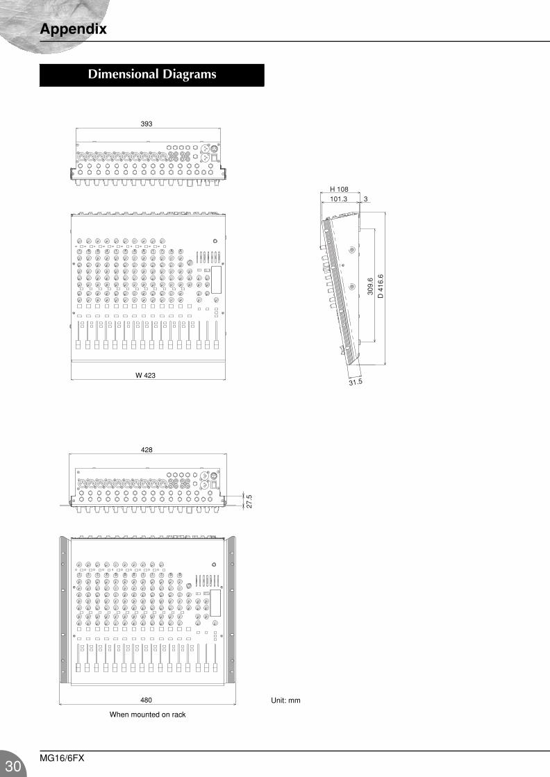
Dimensional Diagrams
393
31.5
309.
6
D 4
16.6
H 108101.3 3
W 423
428
27.5
480
When mounted on rack
Unit: mm
MG16/6FX
Appendix
MG16-6FX.book Page 31 Saturday, January 25, 2003 10:13 AM
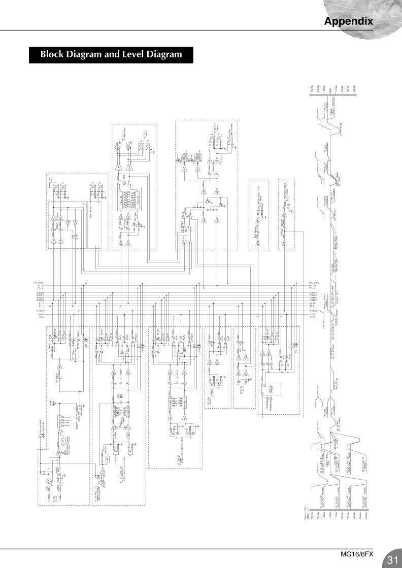
Block Diagram and Level Diagram
MG16/6FX31
MG16-6FX.fm Page 32 Thursday, December 11, 2003 9:16 AM
For details of products, please contact your nearest Yamaha representative or the authorized distributor listed below.
Pour plus de détails sur les produits, veuillez-vous adresser à Yamaha ou au distributeur le plus proche de vous figurant dans la liste suivante.
Die Einzelheiten zu Produkten sind bei Ihrer unten aufgeführten Niederlassung und bei Yamaha Vertragshändlern in den jeweiligen Bestimmungsländern erhältlich.
Para detalles sobre productos, contacte su tienda Yamaha más cercana o el distribuidor autorizado que se lista debajo.
CANADAYamaha Canada Music Ltd.135 Milner Avenue, Scarborough, Ontario,M1S 3R1, CanadaTel: 416-298-1311
U.S.A.Yamaha Corporation of America 6600 Orangethorpe Ave., Buena Park, Calif. 90620, U.S.A.Tel: 714-522-9011
MEXICOYamaha de Mexico S.A. De C.V.,Departamento de ventasJavier Rojo Gomez No.1149, Col. Gpe Del Moral, Deleg. Iztapalapa, 09300 Mexico, D.F.Tel: 55-5804-0600
BRAZILYamaha Musical do Brasil LTDA.Av. Rebouças 2636, São Paulo, BrasilTel: 011-3085-1377
ARGENTINAYamaha Music Latin America, S.A. Sucursal de ArgentinaViamonte 1145 Piso2-B 1053, Buenos Aires, ArgentinaTel: 1-4371-7021
PANAMA AND OTHER LATIN AMERICAN COUNTRIES/CARIBBEAN COUNTRIES
Yamaha Music Latin America, S.A.Torre Banco General, Piso 7, Urbanización Marbella, Calle 47 y Aquilino de la Guardia, Ciudad de Panamá, Panamá Tel: +507-269-5311
THE UNITED KINGDOMYamaha-Kemble Music (U.K.) Ltd.Sherbourne Drive, Tilbrook, Milton Keynes, MK7 8BL, EnglandTel: 01908-366700
GERMANYYamaha Music Central Europe GmbHSiemensstraße 22-34, 25462 Rellingen, GermanyTel: 04101-3030
SWITZERLAND/LIECHTENSTEINYamaha Music Central Europe GmbH, Branch SwitzerlandSeefeldstrasse 94, 8008 Zürich, SwitzerlandTel: 01-383 3990
AUSTRIAYamaha Music Central Europe GmbH, Branch AustriaSchleiergasse 20, A-1100 Wien, AustriaTel: 01-60203900
THE NETHERLANDSYamaha Music Central Europe, Branch NederlandClarissenhof 5-b, 4133 AB Vianen, The NetherlandsTel: 0347-358 040
BELGIUM/LUXEMBOURGYamaha Music Central Europe GmbH, Branch BelgiumRue de Geneve (Genevastraat) 10, 1140 - Brussels, BelgiumTel: 02-726 6032
FRANCEYamaha Musique France BP 70-77312 Marne-la-Vallée Cedex 2, FranceTel: 01-64-61-4000
ITALYYamaha Musica Italia S.P.A. Combo DivisionViale Italia 88, 20020 Lainate (Milano), Italy Tel: 02-935-771
SPAIN/PORTUGALYamaha-Hazen Música, S.A.Ctra. de la Coruna km. 17, 200, 28230 Las Rozas (Madrid), SpainTel: 91-639-8888
SWEDENYamaha Scandinavia ABJ. A. Wettergrens Gata 1Box 30053S-400 43 Göteborg, SwedenTel: 031 89 34 00
DENMARKYS Copenhagen Liaison OfficeGeneratorvej 8B DK-2730 Herlev, DenmarkTel: 44 92 49 00
NORWAYNorsk filial av Yamaha Scandinavia AB Grini Næringspark 1N-1345 Østerås, Norway Tel: 67 16 77 70
OTHER EUROPEAN COUNTRIESYamaha Music Central Europe GmbHSiemensstraße 22-34, 25462 Rellingen, GermanyTel: +49-4101-3030
Yamaha Corporation, Asia-Pacific Music Marketing GroupNakazawa-cho 10-1, Hamamatsu, Japan 430-8650Tel: +81-53-460-2313
TURKEY/CYPRUSYamaha Music Central Europe GmbHSiemensstraße 22-34, 25462 Rellingen, GermanyTel: 04101-3030
OTHER COUNTRIESYamaha Music Gulf FZELB21-128 Jebel Ali Freezone P.O.Box 17328, Dubai, U.A.E.Tel: +971-4-881-5868
THE PEOPLE’S REPUBLIC OF CHINAYamaha Music & Electronics (China) Co.,Ltd.25/F., United Plaza, 1468 Nanjing Road (West),Jingan, Shanghai, ChinaTel: 021-6247-2211
INDONESIAPT. Yamaha Music Indonesia (Distributor)PT. NusantikGedung Yamaha Music Center, Jalan Jend. Gatot Subroto Kav. 4, Jakarta 12930, IndonesiaTel: 21-520-2577
KOREAYamaha Music Korea Ltd.Tong-Yang Securities Bldg. 16F 23-8 Yoido-dong, Youngdungpo-ku, Seoul, KoreaTel: 02-3770-0660
MALAYSIAYamaha Music Malaysia, Sdn., Bhd.Lot 8, Jalan Perbandaran, 47301 Kelana Jaya, Petaling Jaya, Selangor, MalaysiaTel: 3-78030900
SINGAPOREYamaha Music Asia Pte., Ltd.No.11 Ubi Road 1, No.06-02, Meiban Industrial Building, SingaporeTel: 747-4374
TAIWANYamaha KHS Music Co., Ltd. 3F, #6, Sec.2, Nan Jing E. Rd. Taipei.Taiwan 104, R.O.C.Tel: 02-2511-8688
THAILANDSiam Music Yamaha Co., Ltd.891/1 Siam Motors Building, 15-16 floorRama 1 road, Wangmai, PathumwanBangkok 10330, ThailandTel: 02-215-2626
OTHER ASIAN COUNTRIES Yamaha Corporation,Asia-Pacific Music Marketing GroupNakazawa-cho 10-1, Hamamatsu, Japan 430-8650Tel: +81-53-460-2317
AUSTRALIAYamaha Music Australia Pty. Ltd.Level 1, 99 Queensbridge Street, Southbank, Victoria 3006, AustraliaTel: 3-9693-5111
COUNTRIES AND TRUST TERRITORIES IN PACIFIC OCEAN
Yamaha Corporation,Asia-Pacific Music Marketing GroupNakazawa-cho 10-1, Hamamatsu, Japan 430-8650Tel: +81-53-460-2313
NORTH AMERICA
CENTRAL & SOUTH AMERICA
EUROPE
AFRICA
MIDDLE EAST
ASIA
OCEANIA
HEAD OFFICE Yamaha Corporation, Pro Audio & Digital Musical Instrument DivisionNakazawa-cho 10-1, Hamamatsu, Japan 430-8650Tel: +81-53-460-2441
PA09
U.R.G., Pro Audio & Digital Musical Instrument Division, Yamaha Corporation© 2003 Yamaha Corporation
V981750 312CRCR1.3-07C0Printed in China
Yamaha Manual Libraryhttp://www2.yamaha.co.jp/manual/english/