Embed Size (px)
Citation preview
031
1102
(1)C
-(CH)
BU,
Prin
ted
in Ja
pan
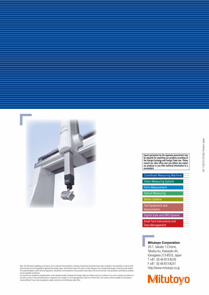
Mitutoyo Corporation20-1, Sakado 1-Chome,Takatsu-ku, Kawasaki-shi,Kanagawa 213-8533, JapanT +81 (0) 44 813-8230F +81 (0) 44 813-8231http://www.mitutoyo.co.jp
Note: All information regarding our products, and in particular the illustrations, drawings, dimensional and performance data contained in this pamphlet, as well as other technical data are to be regarded as approximate average values. We therefore reserve the right to make changes to the corresponding designs, dimensions and weights. The stated standards, similar technical regulations, descriptions and illustrations of the products were valid at the time of printing. Only quotations submitted by ourselves may be regarded as definitive.Our products are classified as regulated items under Japanese Foreign Exchange and Foreign Trade Law. Please consult us in advance if you wish to export our products to any other country. If the purchased product is exported, even though it is not a regulated item (Catch-All controls item), the customer service available for that product may be affected. If you have any questions, please consult your local Mitutoyo sales office.
Export permission by the Japanese government may be required for exporting our products according to the Foreign Exchange and Foreign Trade Law. Please consult our sales office near you before you export our products or you offer technical information to a nonresident.
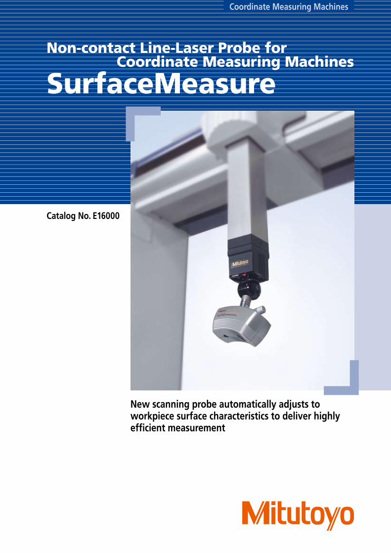
Coordinate Measuring Machines
Catalog No. E16000
Non-contact Line-Laser Probe for Coordinate Measuring Machines
SurfaceMeasure
New scanning probe automatically adjusts to workpiece surface characteristics to deliver highly efficient measurement
2
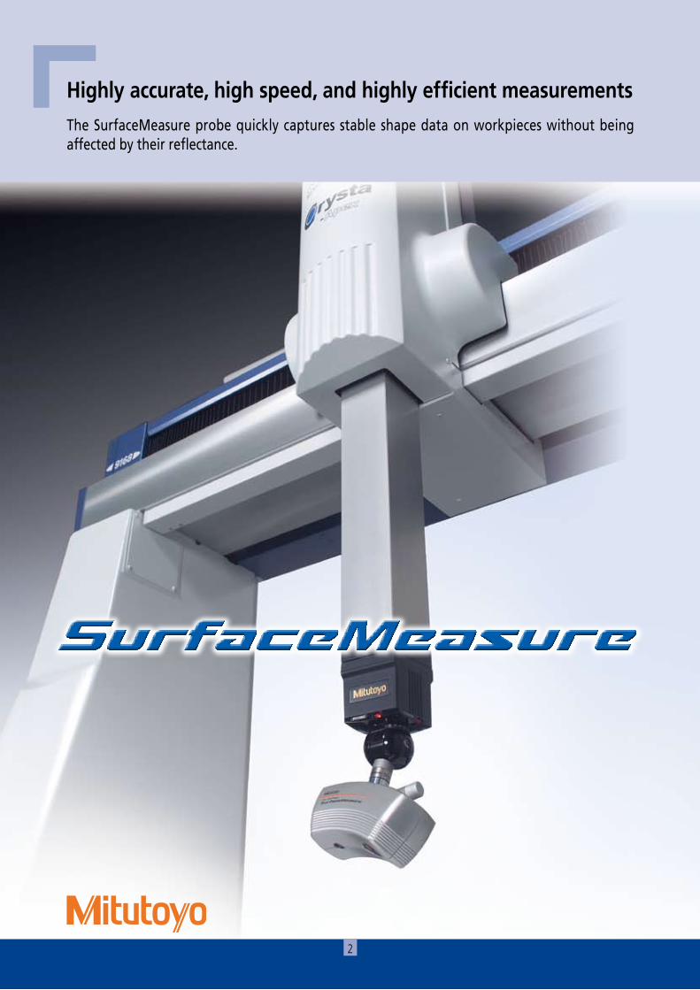
Highly accurate, high speed, and highly efficient measurementsThe SurfaceMeasure probe quickly captures stable shape data on workpieces without being affected by their reflectance.
3
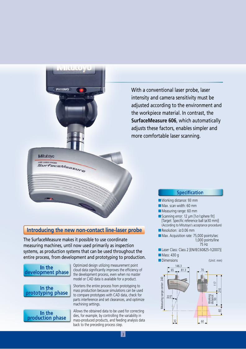
With a conventional laser probe, laser intensity and camera sensitivity must be adjusted according to the environment and the workpiece material. In contrast, the SurfaceMeasure 606, which automatically adjusts these factors, enables simpler and more comfortable laser scanning.
Specification
In the development phase
In the prototyping phase
In the production phase
■Working distance: 93 mm■Max. scan width: 60 mm■Measuring range: 60 mm■Scanning error: 12 µm [1σ/ sphere fit] [Target: Specific reference ball (ø30 mm)] (According to Mitutoyo’s acceptance procedure)■Resolution: ≧0.06 mm■Max. Acquisition rate: 75,000 points/sec 1,000 points/line 75 Hz■Laser Class: Class 2 [EN/IEC60825-1(2007)]■Mass: 430 g■Dimensions (Unit: mm)
60
70
32
60
65146.3
81.3
210
117
Wor
king
dist
ance
: 93
Mea
surin
g ra
nge
cent
er: 2
40
22.5°
Optimized design utilizing measurement point cloud data significantly improves the efficiency of the development process, even when no master model or CAD data is available for a product.
Shortens the entire process from prototyping to mass production because simulations can be used to compare prototypes with CAD data, check for parts interference and set clearances, and optimize machining settings.
Allows the obtained data to be used for correcting dies, for example, by controlling the variability in mass-produced products, and feeding analysis data back to the preceding process step.
Introducing the new non-contact line-laser probe
The SurfaceMeasure makes it possible to use coordinate measuring machines, until now used primarily as inspection systems, as production systems that can be used throughout the entire process, from development and prototyping to production.
4
Non-contact Line-Laser Probe Made by MitutoyoNow you can measure a workpiece without being concerned about its color tone or glossiness.
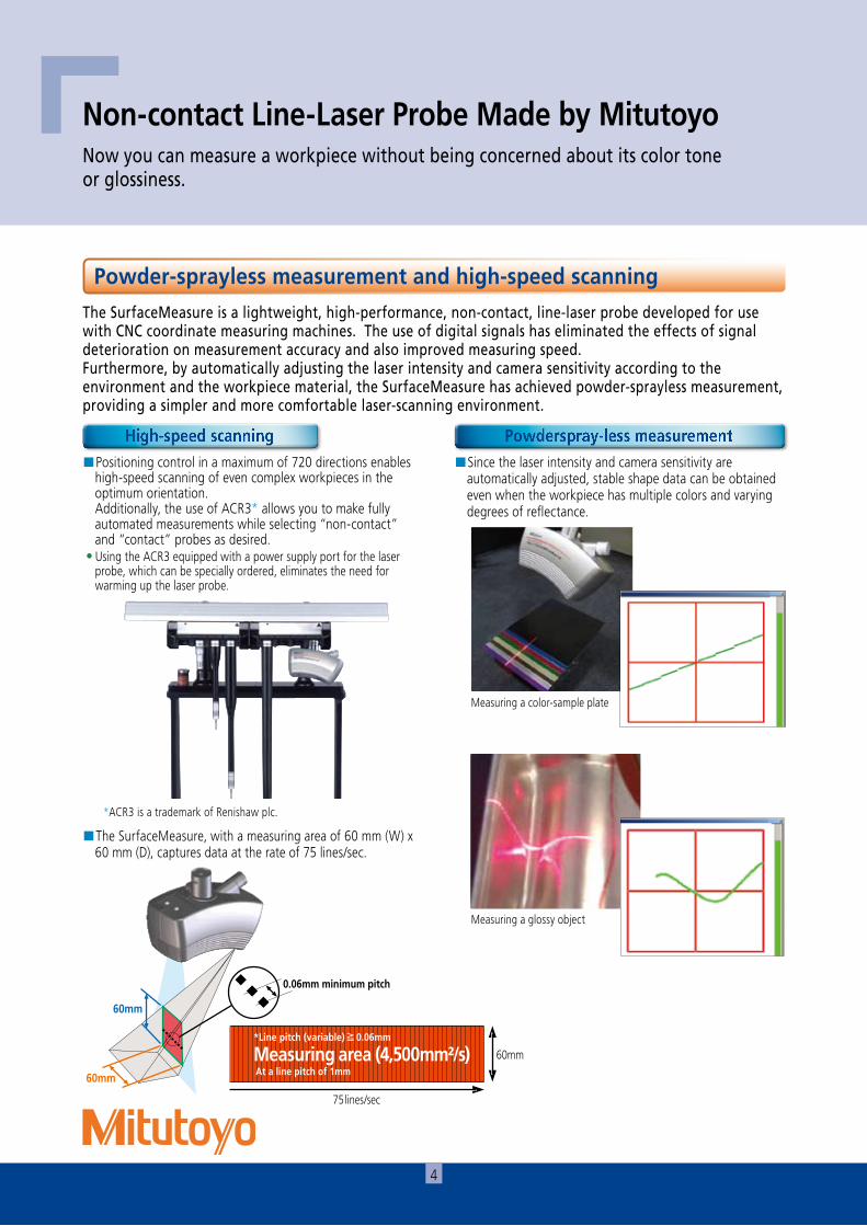
■Positioning control in a maximum of 720 directions enables high-speed scanning of even complex workpieces in the optimum orientation.
Additionally, the use of ACR3* allows you to make fully automated measurements while selecting “non-contact” and “contact” probes as desired.
• Using the ACR3 equipped with a power supply port for the laser probe, which can be specially ordered, eliminates the need for warming up the laser probe.
■Since the laser intensity and camera sensitivity are automatically adjusted, stable shape data can be obtained even when the workpiece has multiple colors and varying degrees of reflectance.
■The SurfaceMeasure, with a measuring area of 60 mm (W) x 60 mm (D), captures data at the rate of 75 lines/sec.
Measuring a color-sample plate
Measuring a glossy object
The SurfaceMeasure is a lightweight, high-performance, non-contact, line-laser probe developed for use with CNC coordinate measuring machines. The use of digital signals has eliminated the effects of signal deterioration on measurement accuracy and also improved measuring speed. Furthermore, by automatically adjusting the laser intensity and camera sensitivity according to the environment and the workpiece material, the SurfaceMeasure has achieved powder-sprayless measurement, providing a simpler and more comfortable laser-scanning environment.
黒青
赤緑
金銅
銀紫
*ACR3 is a trademark of Renishaw plc.
60mm
60mm
0.06mm minimum pitch
Powder-sprayless measurement and high-speed scanning
High-speed scanning Powderspray-less measurement
20~162mm
45~90ライン/秒
測定領域 (1200~7290 mm²/s)
TDS-H
60mm
75lines/sec
*Line pitch (variable)≧0.06mm
Measuring area (4,500mm²/s) At a line pitch of 1mm
5
Off-line teaching software to improve work efficiencyIf model data is available, you can create measurement macros even if you don’t have the actual workpiece.
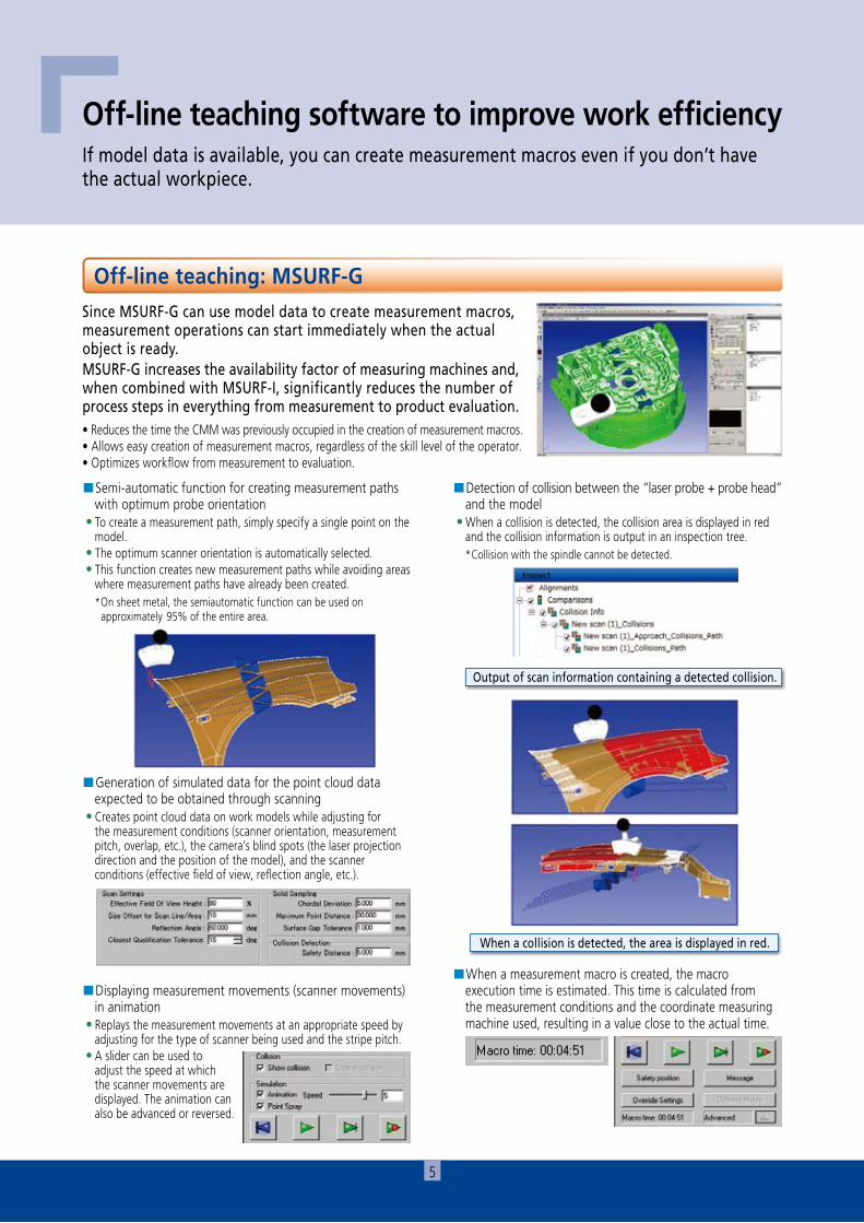
Since MSURF-G can use model data to create measurement macros, measurement operations can start immediately when the actual object is ready.MSURF-G increases the availability factor of measuring machines and, when combined with MSURF-I, significantly reduces the number of process steps in everything from measurement to product evaluation.
■Semi-automatic function for creating measurement paths with optimum probe orientation
• To create a measurement path, simply specify a single point on the model.
• The optimum scanner orientation is automatically selected. • This function creates new measurement paths while avoiding areas
where measurement paths have already been created.*On sheet metal, the semiautomatic function can be used on
approximately 95% of the entire area.
■Generation of simulated data for the point cloud data expected to be obtained through scanning
• Creates point cloud data on work models while adjusting for the measurement conditions (scanner orientation, measurement pitch, overlap, etc.), the camera’s blind spots (the laser projection direction and the position of the model), and the scanner conditions (effective field of view, reflection angle, etc.).
■Detection of collision between the “laser probe + probe head” and the model
• When a collision is detected, the collision area is displayed in red and the collision information is output in an inspection tree.*Collision with the spindle cannot be detected.
■Displaying measurement movements (scanner movements) in animation
• Replays the measurement movements at an appropriate speed by adjusting for the type of scanner being used and the stripe pitch.
• A slider can be used to adjust the speed at which the scanner movements are displayed. The animation can also be advanced or reversed.
■When a measurement macro is created, the macro execution time is estimated. This time is calculated from the measurement conditions and the coordinate measuring machine used, resulting in a value close to the actual time.
When a collision is detected, the area is displayed in red.
Output of scan information containing a detected collision.
• Reduces the time the CMM was previously occupied in the creation of measurement macros.• Allows easy creation of measurement macros, regardless of the skill level of the operator.• Optimizes workflow from measurement to evaluation.
Off-line teaching: MSURF-G
6
Providing Measurement Solutions with Non-Contact Line- Laser Probes to Strengthen Manufacturing CapabilityReducing the measurement, inspection, and analysis processes through high-speed data collection. Enabling easy measurement of curved shapes, producing data that can be used in reverse engineering.
Note: If ACR3 is not used, the probe must be manually changed.
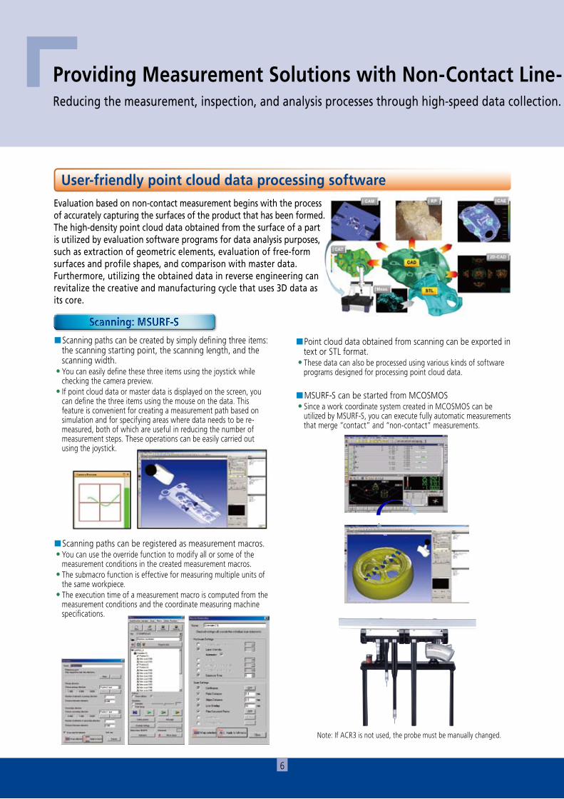
■Scanning paths can be created by simply defining three items: the scanning starting point, the scanning length, and the scanning width.
• You can easily define these three items using the joystick while checking the camera preview.
• If point cloud data or master data is displayed on the screen, you can define the three items using the mouse on the data. This feature is convenient for creating a measurement path based on simulation and for specifying areas where data needs to be re-measured, both of which are useful in reducing the number of measurement steps. These operations can be easily carried out using the joystick.
■Point cloud data obtained from scanning can be exported in text or STL format.
• These data can also be processed using various kinds of software programs designed for processing point cloud data.
■MSURF-S can be started from MCOSMOS • Since a work coordinate system created in MCOSMOS can be
utilized by MSURF-S, you can execute fully automatic measurements that merge “contact” and “non-contact” measurements.
■Scanning paths can be registered as measurement macros. • You can use the override function to modify all or some of the
measurement conditions in the created measurement macros. • The submacro function is effective for measuring multiple units of
the same workpiece. • The execution time of a measurement macro is computed from the
measurement conditions and the coordinate measuring machine specifications.
Evaluation based on non-contact measurement begins with the process of accurately capturing the surfaces of the product that has been formed.The high-density point cloud data obtained from the surface of a part is utilized by evaluation software programs for data analysis purposes, such as extraction of geometric elements, evaluation of free-form surfaces and profile shapes, and comparison with master data.Furthermore, utilizing the obtained data in reverse engineering can revitalize the creative and manufacturing cycle that uses 3D data as its core.
User-friendly point cloud data processing software
Scanning: MSURF-S
7
Providing Measurement Solutions with Non-Contact Line- Laser Probes to Strengthen Manufacturing CapabilityReducing the measurement, inspection, and analysis processes through high-speed data collection. Enabling easy measurement of curved shapes, producing data that can be used in reverse engineering.
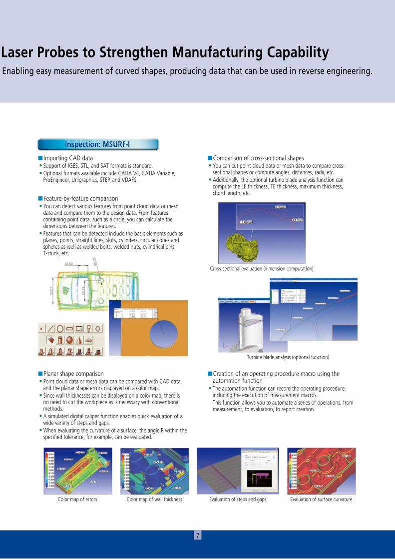
Color map of errors Color map of wall thickness Evaluation of steps and gaps
Cross-sectional evaluation (dimension computation)
Turbine blade analysis (optional function)
Evaluation of surface curvature
■ Importing CAD data • Support of IGES, STL, and SAT formats is standard. • Optional formats available include CATIA V4, CATIA Variable,
ProEngineer, Unigraphics, STEP, and VDAFS.
■Comparison of cross-sectional shapes • You can cut point cloud data or mesh data to compare cross-
sectional shapes or compute angles, distances, radii, etc. • Additionally, the optional turbine blade analysis function can
compute the LE thickness, TE thickness, maximum thickness, chord length, etc.
■Creation of an operating procedure macro using the automation function
• The automation function can record the operating procedure, including the execution of measurement macros.
This function allows you to automate a series of operations, from measurement, to evaluation, to report creation.
■Feature-by-feature comparison • You can detect various features from point cloud data or mesh
data and compare them to the design data. From features containing point data, such as a circle, you can calculate the dimensions between the features.
• Features that can be detected include the basic elements such as planes, points, straight lines, slots, cylinders, circular cones and spheres as well as welded bolts, welded nuts, cylindrical pins, T-studs, etc.
■Planar shape comparison • Point cloud data or mesh data can be compared with CAD data,
and the planar shape errors displayed on a color map. • Since wall thicknesses can be displayed on a color map, there is
no need to cut the workpiece as is necessary with conventional methods.
• A simulated digital caliper function enables quick evaluation of a wide variety of steps and gaps.
• When evaluating the curvature of a surface, the angle R within the specified tolerance, for example, can be evaluated.
Inspection: MSURF-I