Embed Size (px)
Citation preview
14-1
GROUP 14
CONTENTS
GENERAL DESCRIPTION. . . . . . . . . 14-2
SPECIAL TOOL . . . . . . . . . . . . . . . . . 14-2
ENGINE COOLING DIAGNOSIS . . . . 14-2INTRODUCTION. . . . . . . . . . . . . . . . . . . . . 14-2TROUBLESHOOTING STRATEGY . . . . . . 14-2SYMPTOM CHART. . . . . . . . . . . . . . . . . . . 14-2SYMPTOM PROCEDURES . . . . . . . . . . . . 14-3
ON-VEHICLE SERVICE. . . . . . . . . . . 14-5ENGINE COOLANT LEAK CHECK . . . . . . 14-5RADIATOR CAP PRESSURE CHECK. . . . 14-5ENGINE COOLANT REPLACEMENT . . . . 14-5ENGINE COOLANT CONCENTRATION TEST. . . . . . . . . . . . . . . . . . . . . . . . . . . . . . 14-7DRIVE BELT TENSION CHECK AND ADJUSTMENT . . . . . . . . . . . . . . . . . . . . . . 14-7
RADIATOR. . . . . . . . . . . . . . . . . . . . . 14-8RADIATOR REMOVAL AND INSTALLATION. . . . . . . . . . . . . . . . . . . . . . 14-8
COOLING FAN . . . . . . . . . . . . . . . . . . 14-10REMOVAL AND INSTALLATION . . . . . . . . 14-10INSPECTION. . . . . . . . . . . . . . . . . . . . . . . . 14-12
THERMOSTAT . . . . . . . . . . . . . . . . . . 14-13REMOVAL AND INSTALLATION . . . . . . . . 14-13INSPECTION. . . . . . . . . . . . . . . . . . . . . . . . 14-14
WATER PUMP . . . . . . . . . . . . . . . . . . 14-15REMOVAL AND INSTALLATION . . . . . . . . 14-15
WATER HOSE AND WATER PIPE . . 14-17REMOVAL AND INSTALLATION . . . . . . . . 14-17INSPECTION. . . . . . . . . . . . . . . . . . . . . . . . 14-19
SPECIFICATIONS . . . . . . . . . . . . . . . 14-19FASTENER TIGHTENING SPECIFICATION . . . . . . . . . . . . . . . . . . . . . 14-19SERVICE SPECIFICATION . . . . . . . . . . . . 14-20CAPACITIES . . . . . . . . . . . . . . . . . . . . . . . . 14-20
GENERAL DESCRIPTIONENGINE COOLING14-2
.
GENERAL DESCRIPTIONM1141000100304
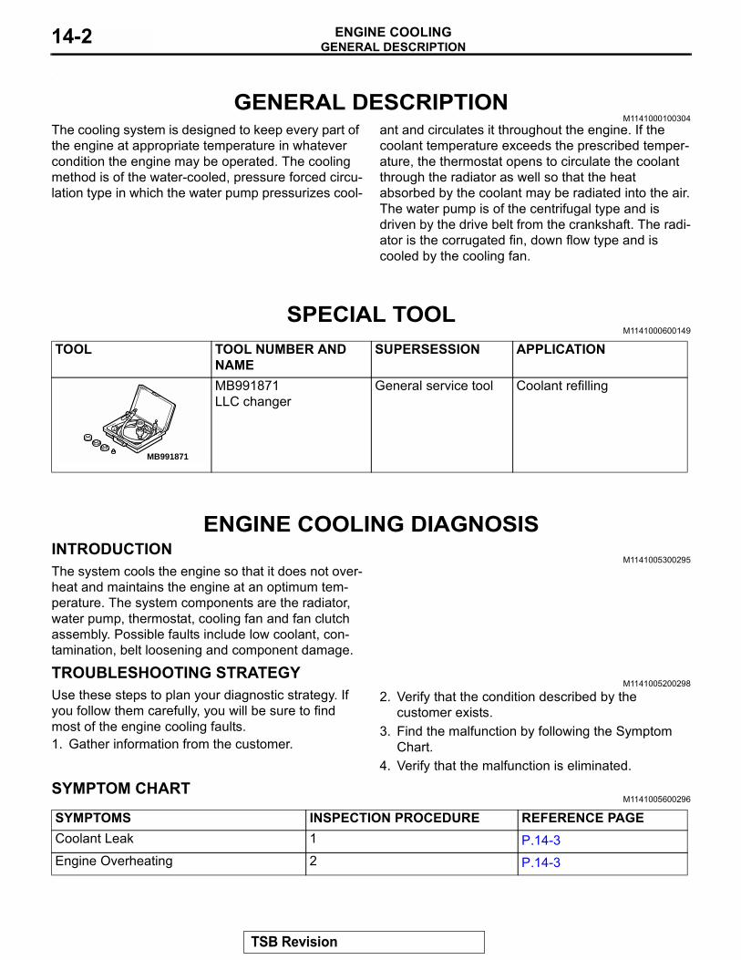
The cooling system is designed to keep every part of the engine at appropriate temperature in whatever condition the engine may be operated. The cooling method is of the water-cooled, pressure forced circu-lation type in which the water pump pressurizes cool-
ant and circulates it throughout the engine. If the coolant temperature exceeds the prescribed temper-ature, the thermostat opens to circulate the coolant through the radiator as well so that the heat absorbed by the coolant may be radiated into the air.The water pump is of the centrifugal type and is driven by the drive belt from the crankshaft. The radi-ator is the corrugated fin, down flow type and is cooled by the cooling fan.
SPECIAL TOOLM1141000600149
ENGINE COOLING DIAGNOSISINTRODUCTION
M1141005300295The system cools the engine so that it does not over-heat and maintains the engine at an optimum tem-perature. The system components are the radiator, water pump, thermostat, cooling fan and fan clutch assembly. Possible faults include low coolant, con-tamination, belt loosening and component damage.
TROUBLESHOOTING STRATEGYM1141005200298
Use these steps to plan your diagnostic strategy. If you follow them carefully, you will be sure to find most of the engine cooling faults.1. Gather information from the customer.
2. Verify that the condition described by the customer exists.
3. Find the malfunction by following the Symptom Chart.
4. Verify that the malfunction is eliminated.
SYMPTOM CHARTM1141005600296
TOOL TOOL NUMBER AND NAME
SUPERSESSION APPLICATION
MB991871LLC changer
General service tool Coolant refilling
MB991871
SYMPTOMS INSPECTION PROCEDURE REFERENCE PAGECoolant Leak 1 P.14-3Engine Overheating 2 P.14-3
TSB Revision
ENGINE COOLING DIAGNOSISENGINE COOLING 14-3
SYMPTOM PROCEDURES
INSPECTION PROCEDURE 1: Coolant Leak
DIAGNOSIS
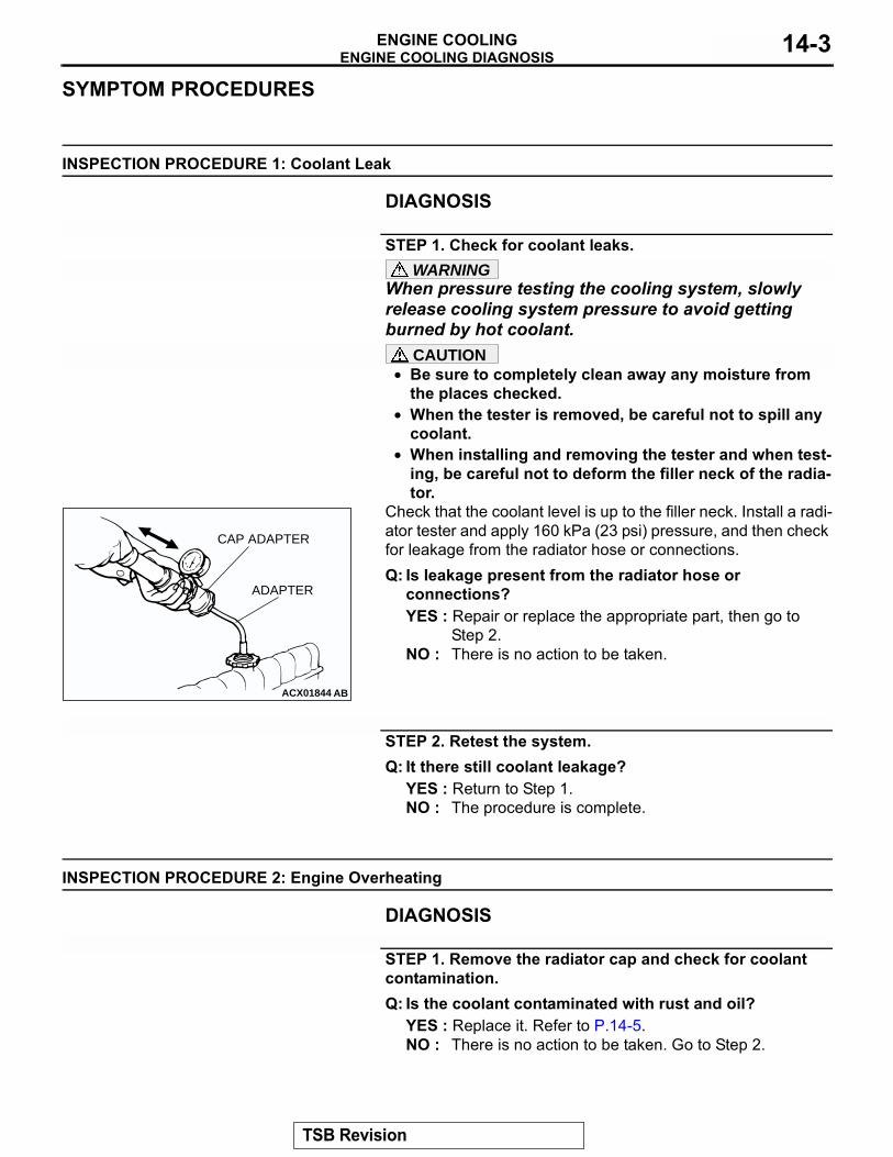
STEP 1. Check for coolant leaks.WARNING
When pressure testing the cooling system, slowly release cooling system pressure to avoid getting burned by hot coolant.
CAUTION• Be sure to completely clean away any moisture from
the places checked.• When the tester is removed, be careful not to spill any
coolant.• When installing and removing the tester and when test-
ing, be careful not to deform the filler neck of the radia-tor.
Check that the coolant level is up to the filler neck. Install a radi-ator tester and apply 160 kPa (23 psi) pressure, and then check for leakage from the radiator hose or connections.Q: Is leakage present from the radiator hose or
connections?YES : Repair or replace the appropriate part, then go to
Step 2.NO : There is no action to be taken.
STEP 2. Retest the system.Q: It there still coolant leakage?
YES : Return to Step 1.NO : The procedure is complete.
INSPECTION PROCEDURE 2: Engine Overheating
DIAGNOSIS
STEP 1. Remove the radiator cap and check for coolant contamination.Q: Is the coolant contaminated with rust and oil?
YES : Replace it. Refer to P.14-5.NO : There is no action to be taken. Go to Step 2.
ACX01844 AB
CAP ADAPTER
ADAPTER
TSB Revision
ENGINE COOLING DIAGNOSISENGINE COOLING14-4
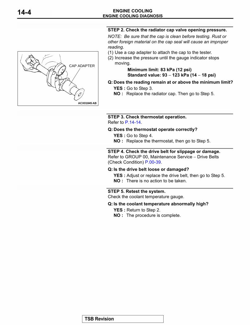
STEP 2. Check the radiator cap valve opening pressure.NOTE: Be sure that the cap is clean before testing. Rust or other foreign material on the cap seal will cause an improper reading.(1) Use a cap adapter to attach the cap to the tester.(2) Increase the pressure until the gauge indicator stops
moving.Minimum limit: 83 kPa (12 psi)Standard value: 93 − 123 kPa (14 − 18 psi)
Q: Does the reading remain at or above the minimum limit?YES : Go to Step 3.NO : Replace the radiator cap. Then go to Step 5.
STEP 3. Check thermostat operation.Refer to P.14-14.Q: Does the thermostat operate correctly?
YES : Go to Step 4.NO : Replace the thermostat, then go to Step 5.
STEP 4. Check the drive belt for slippage or damage.Refer to GROUP 00, Maintenance Service − Drive Belts (Check Condition) P.00-39.Q: Is the drive belt loose or damaged?
YES : Adjust or replace the drive belt, then go to Step 5.NO : There is no action to be taken.
STEP 5. Retest the system.Check the coolant temperature gauge.Q: Is the coolant temperature abnormally high?
YES : Return to Step 2.NO : The procedure is complete.
ACX01845 AB
CAP ADAPTER
TSB Revision
ON-VEHICLE SERVICEENGINE COOLING 14-5
ON-VEHICLE SERVICEENGINE COOLANT LEAK CHECK
M1141001000247
WARNINGWhen pressure testing the cooling system, slowly release cooling system pressure to avoid getting burned by hot coolant.
CAUTION• Be sure to completely clean away any moisture from
the places checked.• When the tester is taken out, be careful not to spill any
coolant.• Be careful when installing and removing the tester and
when testing not to deform the filler neck of the radia-tor.
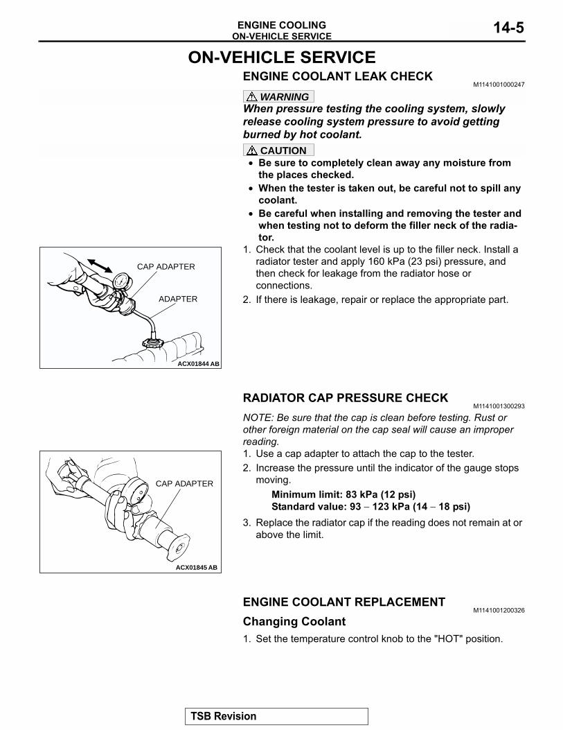
1. Check that the coolant level is up to the filler neck. Install a radiator tester and apply 160 kPa (23 psi) pressure, and then check for leakage from the radiator hose or connections.
2. If there is leakage, repair or replace the appropriate part.
RADIATOR CAP PRESSURE CHECKM1141001300293
NOTE: Be sure that the cap is clean before testing. Rust or other foreign material on the cap seal will cause an improper reading.1. Use a cap adapter to attach the cap to the tester.2. Increase the pressure until the indicator of the gauge stops
moving.Minimum limit: 83 kPa (12 psi)Standard value: 93 − 123 kPa (14 − 18 psi)
3. Replace the radiator cap if the reading does not remain at or above the limit.
ENGINE COOLANT REPLACEMENTM1141001200326
Changing Coolant1. Set the temperature control knob to the "HOT" position.
ACX01844 AB
CAP ADAPTER
ADAPTER
ACX01845 AB
CAP ADAPTER
TSB Revision
ON-VEHICLE SERVICEENGINE COOLING14-6
WARNINGWhen removing the radiator cap, use care to avoid contact with hot coolant or steam. Place a shop towel over the cap and turn the cap counterclockwise a lit-tle to let the pressure escape through the vinyl tube. After relieving the steam pressure, remove the cap by slowly turning it counterclockwise.2. Remove the radiator cap, radiator drain plug and engine
drain plug to drain the coolant.3. Remove the reserve tank and drain the coolant.4. Drain the cooling water then clean the path of the cooling
water by injecting water into the radiator from the radiator cap area.
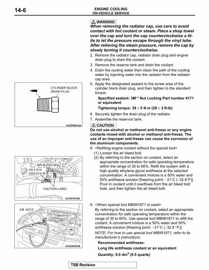
5. Apply the designated sealant to the screw area of the cylinder block drain plug, and then tighten to the standard torque.
Specified sealant: 3M� Nut Locking Part number 4171 or equivalentTightening torque: 39 ± 5 N⋅m (29 ± 3 ft-lb)
6. Securely tighten the drain plug of the radiator.7. Assemble the reservoir tank.
CAUTIONDo not use alcohol or methanol anti-freeze or any engine coolants mixed with alcohol or methanol anti-freeze. The use of an improper anti-freeze can cause the corrosion of the aluminum components.8. <Refilling engine coolant without the special tool>
(1) Loosen the air bleed bolt.(2) By referring to the section on coolant, select an
appropriate concentration for safe operating temperature within the range of 30 to 60%. Refill the system with a high quality ethylene glycol antifreeze at the selected concentration. A convenient mixture is a 50% water and 50% antifreeze solution [freezing point: −31°C (−32.8°F)]. Pour in coolant until it overflows from the air bleed bolt hole, and then tighten the air bleed bolt.
9. <When special tool MB991871 is used>By referring to the section on coolant, select an appropriate concentration for safe operating temperature within the range of 30 to 60%. Use special tool MB991871 to refill the coolant. A convenient mixture is a 50% water and 50% antifreeze solution [freezing point: −31°C (−32.8 °F)].NOTE: For how to use special tool MB991871, refer to its manufacturer�s instructions.
Recommended antifreeze:Long life antifreeze coolant or an equivalentQuantity: 9.0 dm3 (9.5 quarts)
AC200625AB
CYLINDER BLOCKDRAIN PLUG
AC203797AB
CAUTION LABEL
AIR BLEED BOLT
14±1 N·m120±13 in-lb
AC204032AB
AIR HOSE
MB991871
TSB Revision
ON-VEHICLE SERVICEENGINE COOLING 14-7
10.Reinstall the radiator cap.11.Start the engine and let it warm up until the thermostatopens.12.After repeatedly revving the engine up to 3,000 r/min
several times, then stop the engine.13.Remove the radiator cap after the engine has become cold,
and pour in coolant up to the brim. Reinstall the cap.CAUTION
Do not overfill the reserve tank.14.Add coolant to the reserve tank between the "FULL" and
"LOW" mark if necessary.
ENGINE COOLANT CONCENTRATION TESTM1141001100277
Refer to GROUP 00, RECOMMENDED LUBRICANTS AND LUBRICANT CAPACITIES TABLE P.00-31.
DRIVE BELT TENSION CHECK AND ADJUSTMENT
M1141004500100Refer to GROUP 00, Maintenance Service P.00-39.
TSB Revision
RADIATORENGINE COOLING14-8
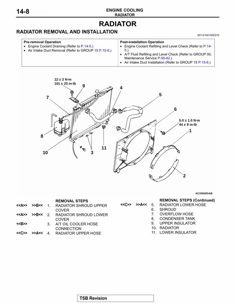
RADIATORRADIATOR REMOVAL AND INSTALLATION
M1141001500316
Pre-removal Operation• Engine Coolant Draining (Refer to P.14-5.)• Air Intake Duct Removal (Refer to GROUP 15 P.15-6.)
Post-installation Operation• Engine Coolant Refilling and Level Check (Refer to P.14-
5.)• A/T Fluid Refilling and Level Check (Refer to GROUP 00,
Maintenance Service P.00-42.)• Air Intake Duct Installation (Refer to GROUP 15 P.15-6.)
ACX00403AB
5.0 ± 1.0 N·m44 ± 9 in-lb
12 ± 2 N·m101 ± 23 in-lb
7
9 4
8
10 311
5
6
1
2
REMOVAL STEPS<<A>> >>B<< 1. RADIATOR SHROUD UPPER
COVER<<A>> >>B<< 2. RADIATOR SHROUD LOWER
COVER<<B>> 3. A/T OIL COOLER HOSE
CONNECTION<<C>> >>A<< 4. RADIATOR UPPER HOSE
<<C>> >>A<< 5. RADIATOR LOWER HOSE6. SHROUD7. OVERFLOW HOSE8. CONDENSER TANK9. UPPER INSULATOR10. RADIATOR11. LOWER INSULATOR
REMOVAL STEPS (Continued)
TSB Revision
RADIATORENGINE COOLING 14-9
REMOVAL SERVICE POINTS.<<A>> RADIATOR SHROUD UPPER COVER/RADIATOR SHROUD LOWER COVER REMOVAL
CAUTIONBe careful not to break or bend the fixing lever by tilting it outward too excessively.Tilt the fixing lever at the shroud housing cover outward slightly, and remove the cover toward the fan axis from its four fixing points. .
<<B>> A/T OIL COOLER HOSE REMOVALAfter removing the hose from the radiator, plug the hose and the radiator nipple to prevent dust or foreign particles from get-ting in..
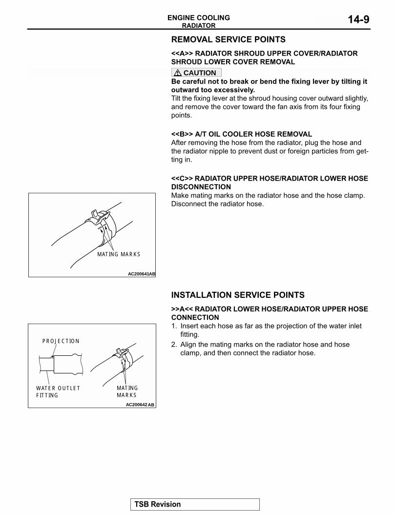
<<C>> RADIATOR UPPER HOSE/RADIATOR LOWER HOSE DISCONNECTIONMake mating marks on the radiator hose and the hose clamp. Disconnect the radiator hose.
INSTALLATION SERVICE POINTS.
>>A<< RADIATOR LOWER HOSE/RADIATOR UPPER HOSE CONNECTION1. Insert each hose as far as the projection of the water inlet
fitting.2. Align the mating marks on the radiator hose and hose
clamp, and then connect the radiator hose.
.
AC200641AB
MATING MARKS
AC200642
MATINGMARKS
PROJECTION
WATER OUTLETFITTING
AB
TSB Revision
COOLING FANENGINE COOLING14-10
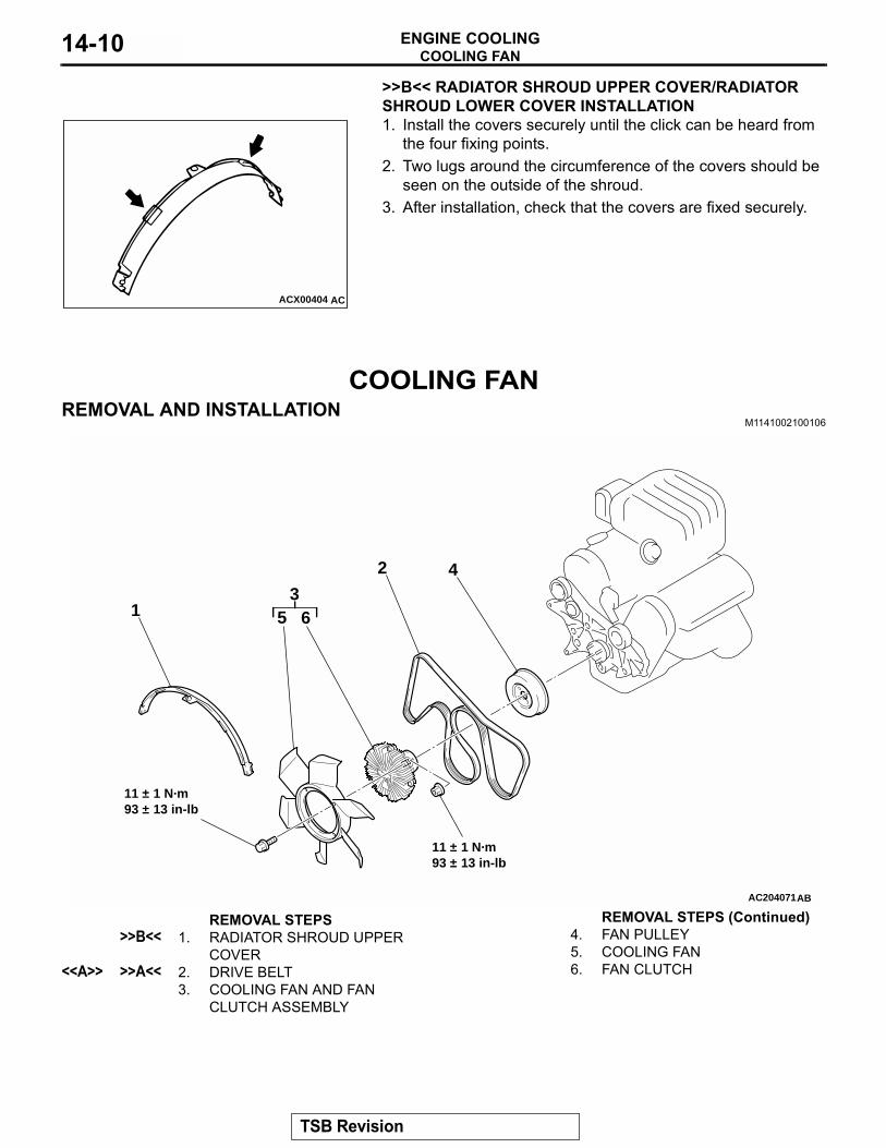
>>B<< RADIATOR SHROUD UPPER COVER/RADIATOR SHROUD LOWER COVER INSTALLATION1. Install the covers securely until the click can be heard from
the four fixing points.2. Two lugs around the circumference of the covers should be
seen on the outside of the shroud.3. After installation, check that the covers are fixed securely.
COOLING FANREMOVAL AND INSTALLATION
M1141002100106
ACX00404 AC
AC204071
1
2
34
5 6
AB
11 ± 1 N·m93 ± 13 in-lb
11 ± 1 N·m93 ± 13 in-lb
REMOVAL STEPS>>B<< 1. RADIATOR SHROUD UPPER
COVER<<A>> >>A<< 2. DRIVE BELT
3. COOLING FAN AND FAN CLUTCH ASSEMBLY
4. FAN PULLEY5. COOLING FAN6. FAN CLUTCH
REMOVAL STEPS (Continued)
TSB Revision
COOLING FANENGINE COOLING 14-11
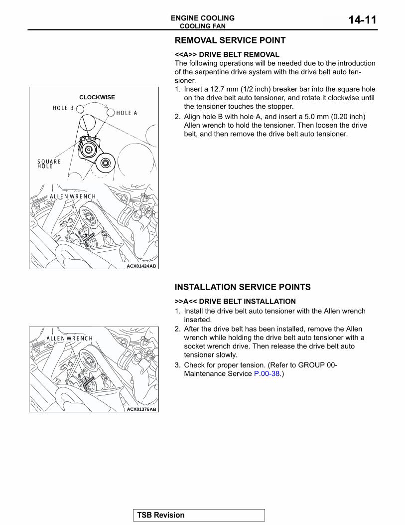
REMOVAL SERVICE POINT.<<A>> DRIVE BELT REMOVALThe following operations will be needed due to the introduction of the serpentine drive system with the drive belt auto ten-sioner.1. Insert a 12.7 mm (1/2 inch) breaker bar into the square hole
on the drive belt auto tensioner, and rotate it clockwise until the tensioner touches the stopper.
2. Align hole B with hole A, and insert a 5.0 mm (0.20 inch) Allen wrench to hold the tensioner. Then loosen the drive belt, and then remove the drive belt auto tensioner.
INSTALLATION SERVICE POINTS.
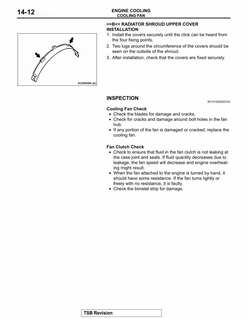
>>A<< DRIVE BELT INSTALLATION1. Install the drive belt auto tensioner with the Allen wrench
inserted. 2. After the drive belt has been installed, remove the Allen
wrench while holding the drive belt auto tensioner with a socket wrench drive. Then release the drive belt auto tensioner slowly.
3. Check for proper tension. (Refer to GROUP 00-Maintenance Service P.00-38.)
.
ACX01424AB
HOLE AHOLE B
SQUARE HOLE
CLOCKWISE
ALLEN WRENCH
ACX01376AB
ALLEN WRENCH
TSB Revision
COOLING FANENGINE COOLING14-12
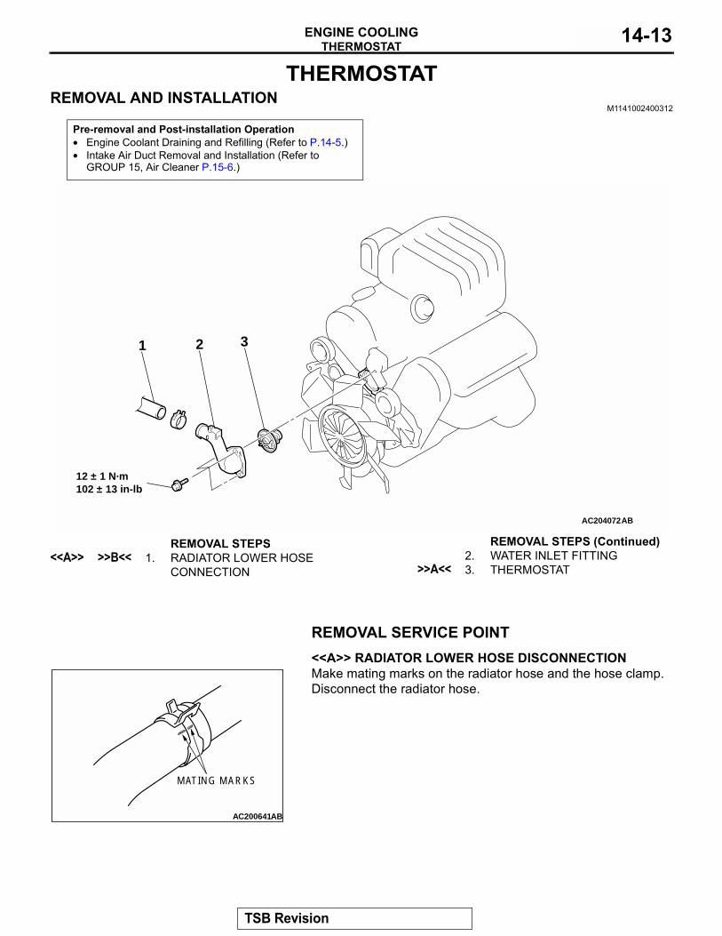
>>B<< RADIATOR SHROUD UPPER COVER INSTALLATION1. Install the covers securely until the click can be heard from
the four fixing points.2. Two lugs around the circumference of the covers should be
seen on the outside of the shroud.3. After installation, check that the covers are fixed securely.
INSPECTIONM1141002200103
.
Cooling Fan Check• Check the blades for damage and cracks.• Check for cracks and damage around bolt holes in the fan
hub.• If any portion of the fan is damaged or cracked, replace the
cooling fan..
Fan Clutch Check• Check to ensure that fluid in the fan clutch is not leaking at
the case joint and seals. If fluid quantity decreases due to leakage, the fan speed will decrease and engine overheat-ing might result.
• When the fan attached to the engine is turned by hand, it should have some resistance. If the fan turns lightly or freely with no resistance, it is faulty.
• Check the bimetal strip for damage.
ACX00404 AC
TSB Revision
THERMOSTATENGINE COOLING 14-13
THERMOSTATREMOVAL AND INSTALLATION
M1141002400312
REMOVAL SERVICE POINT.
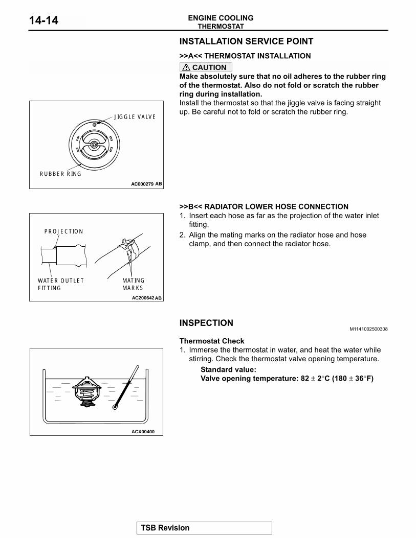
<<A>> RADIATOR LOWER HOSE DISCONNECTIONMake mating marks on the radiator hose and the hose clamp. Disconnect the radiator hose.
Pre-removal and Post-installation Operation• Engine Coolant Draining and Refilling (Refer to P.14-5.)• Intake Air Duct Removal and Installation (Refer to
GROUP 15, Air Cleaner P.15-6.)
AC204072
12 ± 1 N·m102 ± 13 in-lb
1 2 3
AB
REMOVAL STEPS<<A>> >>B<< 1. RADIATOR LOWER HOSE
CONNECTION2. WATER INLET FITTING
>>A<< 3. THERMOSTAT
REMOVAL STEPS (Continued)
AC200641AB
MATING MARKS
TSB Revision
THERMOSTATENGINE COOLING14-14
INSTALLATION SERVICE POINT.
>>A<< THERMOSTAT INSTALLATIONCAUTION
Make absolutely sure that no oil adheres to the rubber ring of the thermostat. Also do not fold or scratch the rubber ring during installation.Install the thermostat so that the jiggle valve is facing straight up. Be careful not to fold or scratch the rubber ring.
.
>>B<< RADIATOR LOWER HOSE CONNECTION1. Insert each hose as far as the projection of the water inlet
fitting.2. Align the mating marks on the radiator hose and hose
clamp, and then connect the radiator hose.
INSPECTIONM1141002500308
.
Thermostat Check1. Immerse the thermostat in water, and heat the water while
stirring. Check the thermostat valve opening temperature.Standard value:Valve opening temperature: 82 ± 2°C (180 ± 36°F)
AC000279
JIGGLE VALVE
RUBBER RING
AB
AC200642
MATINGMARKS
PROJECTION
WATER OUTLETFITTING
AB
ACX00400
TSB Revision
WATER PUMPENGINE COOLING 14-15
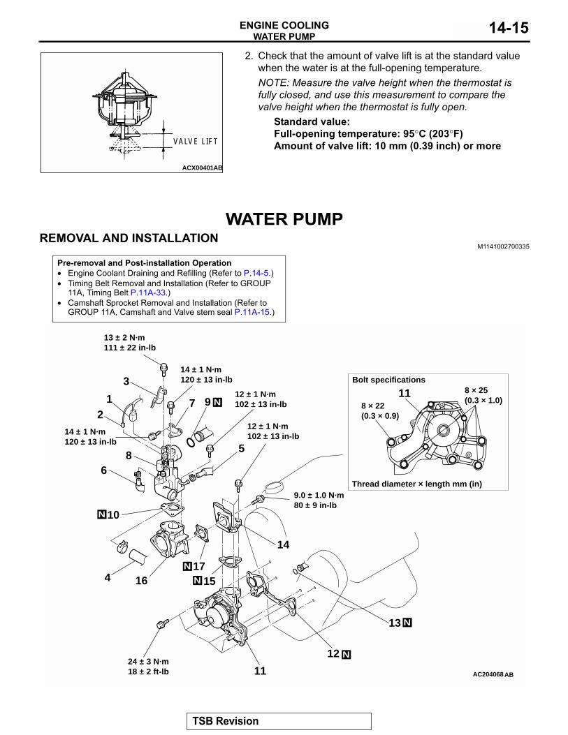
2. Check that the amount of valve lift is at the standard valuewhen the water is at the full-opening temperature.NOTE: Measure the valve height when the thermostat is fully closed, and use this measurement to compare the valve height when the thermostat is fully open.
Standard value:Full-opening temperature: 95°C (203°F)Amount of valve lift: 10 mm (0.39 inch) or more
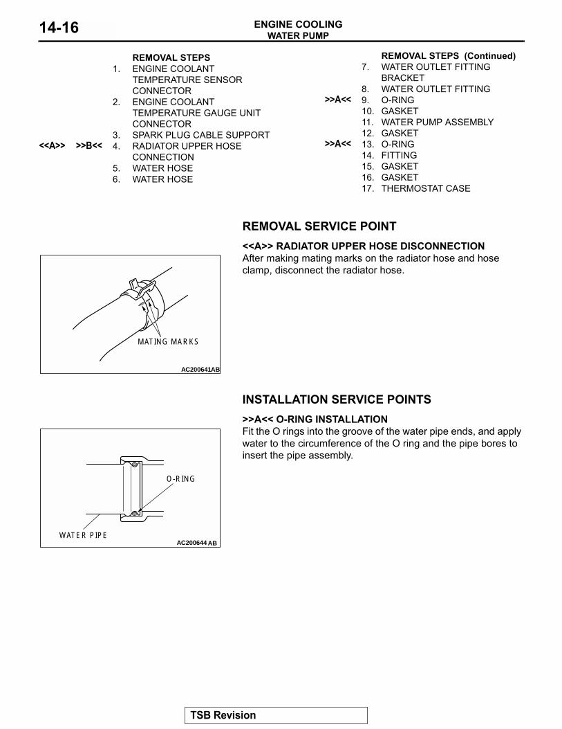
WATER PUMPREMOVAL AND INSTALLATION
M1141002700335
ACX00401AB
VALVE LIFT
Pre-removal and Post-installation Operation• Engine Coolant Draining and Refilling (Refer to P.14-5.)• Timing Belt Removal and Installation (Refer to GROUP
11A, Timing Belt P.11A-33.)• Camshaft Sprocket Removal and Installation (Refer to
GROUP 11A, Camshaft and Valve stem seal P.11A-15.)
AC204068
Bolt specifications
Thread diameter × length mm (in)
8 × 25(0.3 × 1.0)
8 × 22(0.3 × 0.9)
11
14 ± 1 N·m120 ± 13 in-lb
12 ± 1 N·m102 ± 13 in-lb
12 ± 1 N·m102 ± 13 in-lb
9.0 ± 1.0 N·m80 ± 9 in-lb
24 ± 3 N·m18 ± 2 ft-lb
1
5
3
4
2
6
12
13
11
10
7
8
9
N
N
N
N
N
N
AB
14
151617
13 ± 2 N·m111 ± 22 in-lb
14 ± 1 N·m120 ± 13 in-lb
TSB Revision
WATER PUMPENGINE COOLING14-16
REMOVAL SERVICE POINT.
<<A>> RADIATOR UPPER HOSE DISCONNECTIONAfter making mating marks on the radiator hose and hose clamp, disconnect the radiator hose.
INSTALLATION SERVICE POINTS.
>>A<< O-RING INSTALLATIONFit the O rings into the groove of the water pipe ends, and apply water to the circumference of the O ring and the pipe bores to insert the pipe assembly.
.
REMOVAL STEPS 1. ENGINE COOLANT
TEMPERATURE SENSOR CONNECTOR
2. ENGINE COOLANT TEMPERATURE GAUGE UNIT CONNECTOR
3. SPARK PLUG CABLE SUPPORT<<A>> >>B<< 4. RADIATOR UPPER HOSE
CONNECTION5. WATER HOSE6. WATER HOSE
7. WATER OUTLET FITTING BRACKET
8. WATER OUTLET FITTING>>A<< 9. O-RING
10. GASKET11. WATER PUMP ASSEMBLY12. GASKET
>>A<< 13. O-RING14. FITTING15. GASKET16. GASKET17. THERMOSTAT CASE
REMOVAL STEPS (Continued)
AC200641AB
MATING MARKS
AC200644 AB
O-RING
WATER PIPE
TSB Revision
WATER HOSE AND WATER PIPEENGINE COOLING 14-17
>>B<< RADIATOR UPPER HOSE CONNECTION1. Insert each hose as far as the projection of the water outletfitting.2. Align the mating marks on the radiator hose and hose
clamp, and then connect the radiator hose.
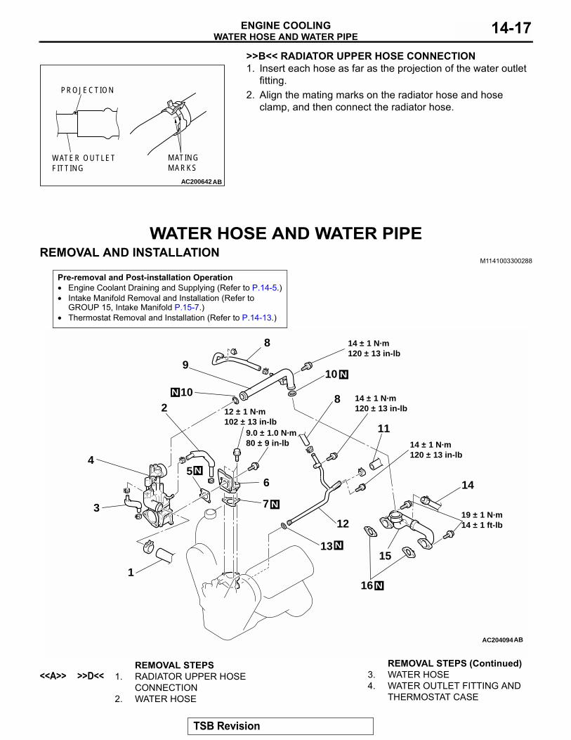
WATER HOSE AND WATER PIPEREMOVAL AND INSTALLATION
M1141003300288
AC200642
MATINGMARKS
PROJECTION
WATER OUTLETFITTING
AB
Pre-removal and Post-installation Operation• Engine Coolant Draining and Supplying (Refer to P.14-5.)• Intake Manifold Removal and Installation (Refer to
GROUP 15, Intake Manifold P.15-7.)• Thermostat Removal and Installation (Refer to P.14-13.)
AC204094
1
2
3
45
6
7
8
8
9
10
11
10
12
13
14
15
16
14 ± 1 N·m120 ± 13 in-lb
14 ± 1 N·m120 ± 13 in-lb
14 ± 1 N·m120 ± 13 in-lb
12 ± 1 N·m102 ± 13 in-lb
9.0 ± 1.0 N·m80 ± 9 in-lb
19 ± 1 N·m14 ± 1 ft-lb
AB
N
N
N
N
N
N
REMOVAL STEPS<<A>> >>D<< 1. RADIATOR UPPER HOSE
CONNECTION2. WATER HOSE
3. WATER HOSE4. WATER OUTLET FITTING AND
THERMOSTAT CASE
REMOVAL STEPS (Continued)
TSB Revision
WATER HOSE AND WATER PIPEENGINE COOLING14-18
REMOVAL SERVICE POINT.
<<A>> RADIATOR UPPER HOSE DISCONNECTIONAfter making mating marks on the radiator hose and hose clamp, disconnect the radiator hose.
INSTALLATION SERVICE POINTS.
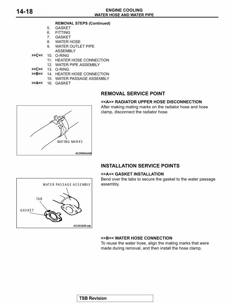
>>A<< GASKET INSTALLATIONBend over the tabs to secure the gasket to the water passage assembly.
.
>>B<< WATER HOSE CONNECTIONTo reuse the water hose, align the mating marks that were made during removal, and then install the hose clamp..
5. GASKET6. FITTING7. GASKET8. WATER HOSE9. WATER OUTLET PIPE
ASSEMBLY>>C<< 10. O-RING
11. HEATER HOSE CONNECTION12. WATER PIPE ASSEMBLY
>>C<< 13. O-RING>>B<< 14. HEATER HOSE CONNECTION
15. WATER PASSAGE ASSEMBLY>>A<< 16. GASKET
REMOVAL STEPS (Continued)
AC200641AB
MATING MARKS
ACX01830
GASKET
TAB
WATER PASSAGE ASSEMBLY
AB
TSB Revision
SPECIFICATIONSENGINE COOLING 14-19
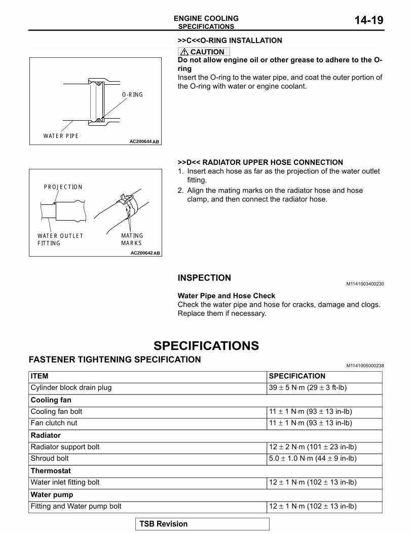
>>C<<O-RING INSTALLATIONCAUTIONDo not allow engine oil or other grease to adhere to the O-ringInsert the O-ring to the water pipe, and coat the outer portion of the O-ring with water or engine coolant.
.
>>D<< RADIATOR UPPER HOSE CONNECTION1. Insert each hose as far as the projection of the water outlet
fitting.2. Align the mating marks on the radiator hose and hose
clamp, and then connect the radiator hose.
INSPECTIONM1141003400230
.
Water Pipe and Hose CheckCheck the water pipe and hose for cracks, damage and clogs. Replace them if necessary.
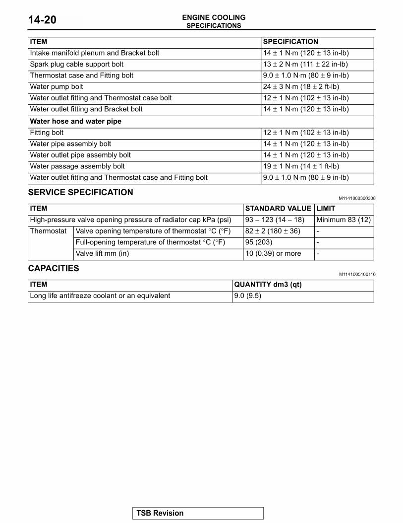
SPECIFICATIONSFASTENER TIGHTENING SPECIFICATION
M1141005000238
AC200644 AB
O-RING
WATER PIPE
AC200642
MATINGMARKS
PROJECTION
WATER OUTLETFITTING
AB
ITEM SPECIFICATIONCylinder block drain plug 39 ± 5 N⋅m (29 ± 3 ft-lb)Cooling fanCooling fan bolt 11 ± 1 N⋅m (93 ± 13 in-lb)Fan clutch nut 11 ± 1 N⋅m (93 ± 13 in-lb)RadiatorRadiator support bolt 12 ± 2 N⋅m (101 ± 23 in-lb)Shroud bolt 5.0 ± 1.0 N⋅m (44 ± 9 in-lb)ThermostatWater inlet fitting bolt 12 ± 1 N⋅m (102 ± 13 in-lb)Water pumpFitting and Water pump bolt 12 ± 1 N⋅m (102 ± 13 in-lb)
TSB Revision
SPECIFICATIONSENGINE COOLING14-20
SERVICE SPECIFICATIONM1141000300308
CAPACITIESM1141005100116
Intake manifold plenum and Bracket bolt 14 ± 1 N⋅m (120 ± 13 in-lb)Spark plug cable support bolt 13 ± 2 N⋅m (111 ± 22 in-lb)Thermostat case and Fitting bolt 9.0 ± 1.0 N⋅m (80 ± 9 in-lb)Water pump bolt 24 ± 3 N⋅m (18 ± 2 ft-lb)Water outlet fitting and Thermostat case bolt 12 ± 1 N⋅m (102 ± 13 in-lb)Water outlet fitting and Bracket bolt 14 ± 1 N⋅m (120 ± 13 in-lb)Water hose and water pipeFitting bolt 12 ± 1 N⋅m (102 ± 13 in-lb)Water pipe assembly bolt 14 ± 1 N⋅m (120 ± 13 in-lb)Water outlet pipe assembly bolt 14 ± 1 N⋅m (120 ± 13 in-lb)Water passage assembly bolt 19 ± 1 N⋅m (14 ± 1 ft-lb)Water outlet fitting and Thermostat case and Fitting bolt 9.0 ± 1.0 N⋅m (80 ± 9 in-lb)
ITEM SPECIFICATION
ITEM STANDARD VALUE LIMITHigh-pressure valve opening pressure of radiator cap kPa (psi) 93 − 123 (14 − 18) Minimum 83 (12)Thermostat Valve opening temperature of thermostat °C (°F) 82 ± 2 (180 ± 36) -
Full-opening temperature of thermostat °C (°F) 95 (203) -Valve lift mm (in) 10 (0.39) or more -
ITEM QUANTITY dm3 (qt)Long life antifreeze coolant or an equivalent 9.0 (9.5)
TSB Revision