Embed Size (px)
Citation preview
• An easy-to-follow guide to achieving a perfect result. • Outlines all the tools you will need for the job.• Includes a materials checklist.
PLEASE NOTE: Before starting this project or buying any materials, it is worth your time to read all steps thoroughly first to be sure you understand what is required.
mitre10.com.auMitre 10 is proudly Australian owned.
MItrePlAn PrOJeCt PlAnner
93 16487 000 268
Your local MITRE 10 Store is:
IMPORTANT: This project planner has been produced to provide basic information and our experienced staff are available to answer any questions you may have. However, this information is provided for use on the understanding that Mitre 10 is not liable for any loss or damage which is suffered or incurred (including but not limited to indirect or consequential loss), for any personal injury or damage to property suffered or sustained as a result of using the information contained in this MitrePlan Project Planner. Mitre 10 advises you to call in a qualified tradesperson, such as an electrician or plumber, where expert services are required, and to independently assess any safety precautions that will need to be followed prior to using the information in this MitrePlan Project Planner.
WARNING: There may be by laws or regulations of councils or other statutory bodies that you must comply with when following this MitrePlan Project Planner.
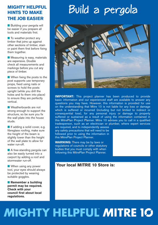
Build a pergola
MIGhTY hELPfuL hINTS TO MAkE ThE jOb EASIER■ Building your pergola will be easier if you prepare all tools and materials first.
■ To weather-protect any timber that joins up against other sections of timber, stain or paint them first before fixing them together.
■ Measuring is easy, materials are expensive. Double check all measurements and markings before you cut any piece of timber.
■ When fixing the posts to the post supports use temporary props, fixed using nails or screws to hold the posts upright (while you drill the holes and fix them into place) to ensure they are perfectly vertical.
■ Weatherboards are not strong enough to support the structure, so be sure you fix the wall plate into the house studs.
■ If adding a solid cover, e.g. fibreglass roofing, make sure the height of the beam is slightly lower than the height of the wall plate to allow for water run-off.
■ A free-standing pergola can also be easily turned into a carport by adding a roof and stormwater run-off.
■ When using any power tool, your eyes should always be protected by wearing suitable goggles.
■ Remember a building permit may be required. Check with your council first about local regulations.
Build a pergola
#1
M10773 MitrePlan #1.indd 1 3/3/09 9:11:30 AM
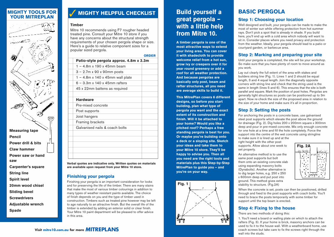
TimberMitre 10 recommends using F7 rougher headed treated pine. Consult your Mitre 10 store if you have any concerns about the structural strength requirements of your chosen pergola shape or size. Here’s a guide to relative component sizes for a popular sized pergola.
Patio-style pergola approx. 4.8m x 3.3m
1 – 4.8m x 190 x 45mm beam 3 – 2.7m x 90 x 90mm posts 1 – 4.8m x 140 x 45mm wall plate 6 – 3.3m x 140 x 45mm rafters 45 x 22mm battens as required
hardware
Pre-mixed concrete Post supports Joist hangers Framing brackets Galvanised nails & coach bolts
MIGhTY TOOLS fOR YOuR MITREPLAN
Verbal quotes are indicative only. Written quotes on materials are available upon request from your Mitre 10 store.
ORDER
MIGhTY hELPfuL ChECkLIST✓
Measuring tape
Pencil
Power drill & bits
Claw hammer
Power saw or hand saw
Carpenter’s square
String line
Spirit level
20mm wood chisel
Sliding bevel
Screwdrivers
Adjustable wrench
Spade
finishing your pergolaFinishing your pergola is an important consideration for looks and for preserving the life of the timber. There are many stains that make the most of various timber colourings in addition to many types of weather resistant paints available. The choice of finish depends on you and the type of timber used in construction. Timbers such as treated pine however may be left to age naturally to an attractive finish. But the overall life of the timber is extended by adding an exterior solid or clear finish. Your Mitre 10 paint department will be pleased to offer advice in this area.
Visit mitre10.com.au for more S
A timber pergola is one of the most attractive ways to extend your living area. You can cover it with shadecloth to provide welcome relief from a hot sun, grow ivy or creepers over it for year round greenery or add a roof for all weather protection. And because pergolas are basically only post, beam and rafter structures, all you need are average skills to build it.
This MitrePlan covers 6 different designs, so before you start building, plan what type of pergola you want and the exact extent of its construction and finish. Will it be attached to your home? Would you like a pitched roof? Perhaps a free standing pergola is best for you. Or maybe you’re building onto a deck or a sloping site. Sketch your ideas and take them to your Mitre 10 store. They’ll be happy to advise you. Then all you need are the right tools and materials plus this Step-by-Step MitrePlan to guide you – and you’re on your way.
build yourself a great pergola – with a little help from Mitre 10.
bASIC PERGOLAStep 1: Choosing your locationWell designed and built, your pergola can be made to make the most of winter sun while offering protection from hot summer rays. Don’t pick a spot that is already in shade. If you build here, you’ll end up with a cold area which nobody will want to sit in. Consider places where you need privacy and protection from the weather. Ideally, your pergola should lead to a patio or courtyard garden, or barbecue area.
Step 2: Marking and preparing your siteUntil your pergola is completed, the site will be your workshop. So make sure that you have plenty of room to move around as you work.
Lay out clearly the full extent of the area with stakes and builders string line (Fig. 1). Lines 1 and 2 should be equal length, 3 and 4 equal length. Join the diagonally opposite corners with string line and check that the string used is the same in length (lines 5 and 6). This ensures that the site is both parallel and square. Mark the position of post holes. Pergolas are generally light structures so posts can be positioned up to 3m apart. Now re-check the size of the proposed area in relation to the size of your home and make sure it’s all in proportion.
Step 3: Setting the postsFor anchoring the posts in a concrete base, use galvanised steel post supports which elevate the post above the ground for drainage (Fig. 2). Dig holes 200 x 200mm square x 300mm deep and pour in pre-mixed concrete. Mix only enough concrete for one hole at a time and fill the hole completely. Force the support into the centre of the wet concrete using stringline to make sure it is lined up and at the right height with the other post supports. Allow about one week to set properly.
An alternative method is to use the same post supports but bolt them onto an existing concrete slab using expanding masonry bolts (Dynabolts). Another alternative is to dig larger holes, e.g. 250 x 250 x 600mm deep and put post into ground. This method gives extra stability to structure. (Fig.2A)
When the concrete is set, posts can then be positioned, drilled through and fixed to the post supports with coach bolts. You’ll need to brace the posts temporarily with some timber for support until the top beam is erected.
Step 4: fixing to the houseThere are two methods of doing this:
1. You’ll need a board or walling plate on which to attach the rafters (Fig. 3). If your home is brick, masonry anchors can be used to fix it to the house wall. With a weatherboard home, use coach screws but take care to fix the screws right through the wall into the studs.
fig. 1
M10773 MitrePlan #1.indd 2 3/3/09 9:11:31 AM
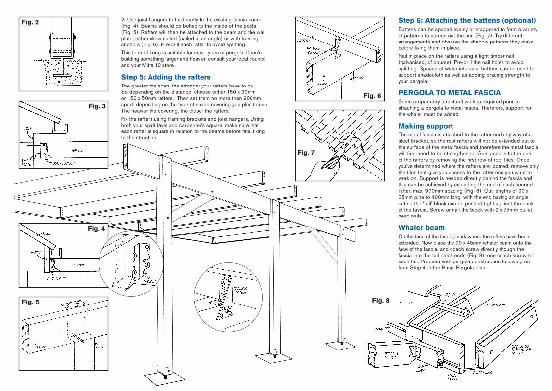
Step 6: Attaching the battens (optional)Battens can be spaced evenly or staggered to form a variety of patterns to screen out the sun (Fig. 7). Try different arrangements and observe the shadow patterns they make before fixing them in place.
Nail in place on the rafters using a light timber nail (galvanised, of course). Pre-drill the nail holes to avoid splitting. Spaced at wider intervals, battens can be used to support shadecloth as well as adding bracing strength to your pergola.
PERGOLA TO METAL fASCIASome preparatory structural work is required prior to attaching a pergola to metal fascia. Therefore, support for the whaler must be added.
Making supportThe metal fascia is attached to the rafter ends by way of a steel bracket, so the roof rafters will not be extended out to the surface of the metal fascia and therefore the metal fascia will first need to be strengthened. Gain access to the end of the rafters by removing the first row of roof tiles. Once you’ve determined where the rafters are located, remove only the tiles that give you access to the rafter end you want to work on. Support is needed directly behind the fascia and this can be achieved by extending the end of each second rafter, max. 900mm spacing (Fig. 8). Cut lengths of 90 x 35mm pine to 400mm long, with the end having an angle cut so the ‘tail’ block can be pushed tight against the back of the fascia. Screw or nail the block with 2 x 75mm bullet head nails.
Whaler beamOn the face of the fascia, mark where the rafters have been extended. Now place the 90 x 45mm whaler beam onto the face of the fascia, and coach screw directly though the fascia into the tail block ends (Fig. 8), one coach screw to each tail. Proceed with pergola construction following on from Step 4 in the Basic Pergola plan.
2. Use joist hangers to fix directly to the existing fascia board (Fig. 4). Beams should be bolted to the inside of the posts (Fig. 5). Rafters will then be attached to the beam and the wall plate, either skew nailed (nailed at an angle) or with framing anchors (Fig. 6). Pre-drill each rafter to avoid splitting.
This form of fixing is suitable for most types of pergola. If you’re building something larger and heavier, consult your local council and your Mitre 10 store.
Step 5: Adding the raftersThe greater the span, the stronger your rafters have to be. So depending on the distance, choose either 150 x 30mm or 150 x 50mm rafters. Then set them no more than 900mm apart, depending on the type of shade covering you plan to use. The heavier the covering, the closer the rafters.
Fix the rafters using framing brackets and joist hangers. Using both your spirit level and carpenter’s square, make sure that each rafter is square in relation to the beams before final fixing to the structure.
fig. 2
fig. 4
fig. 3
fig. 6
fig. 7
fig. 5 fig. 8
M10773 MitrePlan #1.indd 3 3/3/09 9:11:32 AM
fINISh DETAILGive your pergola some personality by adding some design features. A warning though – too much detail can make the job look too cluttered.
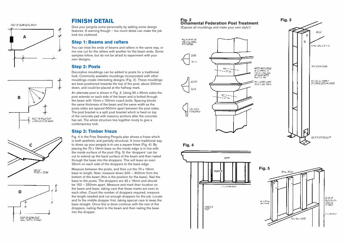
Step 1: beams and raftersYou can treat the ends of beams and rafters in the same way, or mix one cut for the rafters with another for the beam ends. Some samples follow, but do not be afraid to experiment with your own designs.
Step 2: PostsDecorative mouldings can be added to posts for a traditional look. Commonly available mouldings incorporated with other mouldings create interesting designs (Fig. 2). These mouldings are best positioned towards the top of the post, about 200mm down, and could be placed at the halfway mark.
An alternate post is shown in Fig. 3. Using 90 x 35mm sides the post extends on each side of the beam and is bolted through the beam with 10mm x 150mm coach bolts. Spacing blocks the same thickness of the beam and the same width as the posts sides are spaced 600mm apart between the post sides. The post bracket is a split post bracket which is fixed on top of the concrete pad with masonry anchors after the concrete has set. The whole structure ties together nicely to give a contemporary look.
Step 3: Timber friezeFig. 4 in the Free Standing Pergola plan shows a frieze which is both aesthetic and partially structural. A more traditional way to dress up your pergola is to use a square frieze (Fig. 4). By placing the 70 x 19mm base so the inside edge is in line with the inside surface of the post (Fig. 5) the ‘droppers’ can be cut to extend up the back surface of the beam and then nailed through the base into the droppers. This will leave an even 25mm on each side of the droppers to the base edge.
Measure between the posts, and then cut the 70 x 19mm base to length. Next, measure down 200 – 300mm from the bottom of the beam (this is the position for the base). Nail the base to the posts. The droppers are 42 x 19mm and should be 150 – 250mm apart. Measure and mark their location on the beam and base, taking care that these marks are even to each other. Count the number of droppers required, measure the length needed and cut enough droppers for the job. Locate and fix the middle dropper first, taking special care to keep the base straight. Once this is done continue with the rest of the droppers, nailing them to the beam and then nailing the base into the dropper.
fig. 2Ornamental federation Post Treatment(Expose all mouldings and make your own style!)
fig. 4
fig. 3
A
b
C
D
fig. 5
M10773 MitrePlan #1.indd 4 3/3/09 9:11:33 AM
SAfETYBuilding a substantial structure such as a pergola or deck is exciting, and working outdoors with seemingly unlimited space can create a relaxed approach. But take care not to become too relaxed about your work as a casual attitude can be potentially dangerous.
Here are some tips to help you maintain an accident-free work area.
■ Take your time to do the work you have set yourself. If you’re running behind schedule don’t feel pressured to rush through the job – it’s dangerous and can lead to disappointing results.
■ Keep all leads and lead connections off damp ground. Where possible fit leads off the ground regardless of whether or not it’s damp.
■ Unplug or disable all equipment when not in use. Children are easily tempted to try unsupervised power tools. If you’re leaving the site (even for 10 minutes) remove all electrical equipment.
■ Cover all unfilled holes and, if they are to be left for any length of time, cordon off the area to keep people out.
■ Children love watching building projects, but ensure that all children and pets are kept well clear of the work area. They can be distracting to you and could also be a danger to themselves.
■ Cut all timber on a waist-high work bench or saw horse. The timber must be firmly held in place while cutting so you may need to use clamps.
■ Never work with machinery that isn’t in perfect operating order. Check that the safety guard is working properly on your power saw. Make sure all tools are sharp and in good working condition. If they are not, use our tool repair and sharpening services to get all your tools into top condition before you start work.
■ Don’t try to do the entire job yourself. Beams can be heavy and awkward to lift into position by yourself and you'll achieve a better result if you ask someone to lend a hand.
■ Make sure any ladders you’re using are sturdy and safe. Extension ladders must be firmly set into the ground at their base and should be on a angle of about 60 degrees.
■ Keep a tidy site, progressively removing all excess material and rubble. To work safely you need clean, uncluttered space.
■ When removing temporary props or supports check that all temporary nails have been removed from both the structure and the prop timber – they are an accident waiting to happen.
■ Invest in the proper safety equipment. Wear safety glasses all the time and wear ear muffs while operating power tools. A dust mask is also a good idea.
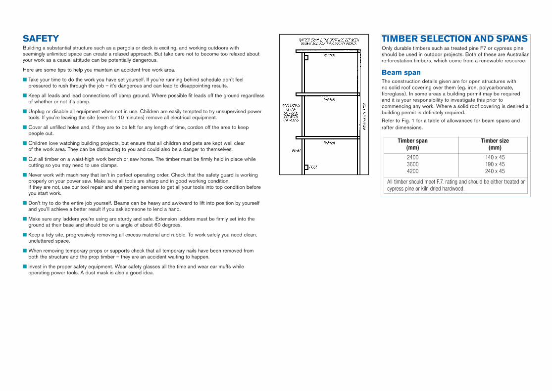
TIMbER SELECTION AND SPANSOnly durable timbers such as treated pine F7 or cypress pine should be used in outdoor projects. Both of these are Australian re-forestation timbers, which come from a renewable resource.
beam spanThe construction details given are for open structures with no solid roof covering over them (eg. iron, polycarbonate, fibreglass). In some areas a building permit may be required and it is your responsibility to investigate this prior to commencing any work. Where a solid roof covering is desired a building permit is definitely required.
Refer to Fig. 1 for a table of allowances for beam spans and rafter dimensions.
Timber span Timber size (mm) (mm)
2400 140 x 45 3600 190 x 45 4200 240 x 45
All timber should meet F.7. rating and should be either treated or cypress pine or kiln dried hardwood.
M10773 MitrePlan #1.indd 5 3/3/09 9:11:34 AM
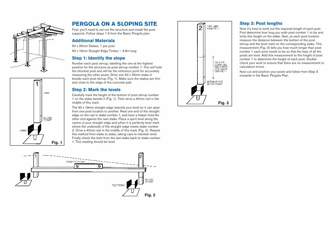
Step 3: Post lengthsNow it’s time to work out the required length of each post. First determine how long you wish post number 1 to be and write this height on the stake. Next, at each post location measure the distance between the bottom of the post stirrup and the level mark on the corresponding stake. This measurement (Fig. 3) tells you how much longer than post number 1 each post needs to be so that the tops of all the posts are level. Add this measurement to the height of post number 1 to determine the height of each post. Double check your work to ensure that there are no measurement or calculation errors.
Now cut and position your posts and follow from Step 3 onwards in the Basic Pergola Plan.
PERGOLA ON A SLOPING SITEFirst, you’ll need to set out the structure and install the post supports. Follow steps 1-3 from the Basic Pergola plan.
Additional Materials50 x 25mm Stakes, 1 per post
90 x 19mm Straight Edge Timber – 3.6m long
Step 1: Identify the slopeNumber each post stirrup, labelling the one at the highest position for the structure as post stirrup number 1. This will hold the shortest post and will be the reference point for accurately measuring the other posts. Drive one 50 x 25mm stake in beside each post stirrup (Fig. 1). Make sure the stakes are firm and close to the edge of the concrete pad.
Step 2: Mark the levelsCarefully mark the height of the bottom of post stirrup number 1 on the stake beside it (Fig. 1). Then drive a 40mm nail in the middle of this mark.
The 90 x 19mm straight edge extends your level so it can span from one post location to another. Rest one end of the straight edge on the nail in stake number 1, and have a helper hold the other end against the next stake. Place a spirit level along the centre of your straight edge and when it is perfectly level mark where the underside of the straight edge meets stake number 2. Drive a 40mm nail in the middle of this mark (Fig. 2). Repeat this method from stake to stake, taking care to maintain level. Finally check the level from the last stake back to stake number 1. This reading should be level.
fig. 3
fig. 2
fig. 1
M10773 MitrePlan #1.indd 6 3/3/09 9:11:34 AM
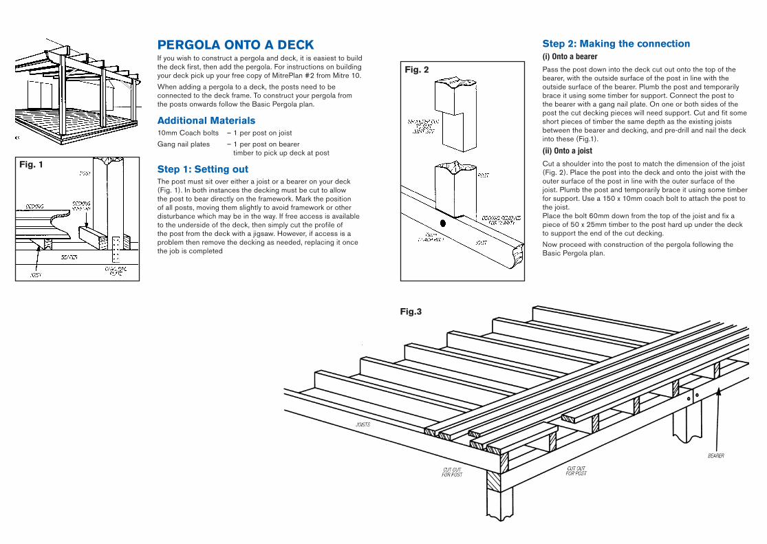
fig.3
PERGOLA ONTO A DECkIf you wish to construct a pergola and deck, it is easiest to build the deck first, then add the pergola. For instructions on building your deck pick up your free copy of MitrePlan #2 from Mitre 10.
When adding a pergola to a deck, the posts need to be connected to the deck frame. To construct your pergola from the posts onwards follow the Basic Pergola plan.
Additional Materials10mm Coach bolts – 1 per post on joist
Gang nail plates – 1 per post on bearer timber to pick up deck at post
Step 1: Setting outThe post must sit over either a joist or a bearer on your deck (Fig. 1). In both instances the decking must be cut to allow the post to bear directly on the framework. Mark the position of all posts, moving them slightly to avoid framework or other disturbance which may be in the way. If free access is available to the underside of the deck, then simply cut the profile of the post from the deck with a jigsaw. However, if access is a problem then remove the decking as needed, replacing it once the job is completed
fig. 2
fig. 1
Step 2: Making the connection(i) Onto a bearer
Pass the post down into the deck cut out onto the top of the bearer, with the outside surface of the post in line with the outside surface of the bearer. Plumb the post and temporarily brace it using some timber for support. Connect the post to the bearer with a gang nail plate. On one or both sides of the post the cut decking pieces will need support. Cut and fit some short pieces of timber the same depth as the existing joists between the bearer and decking, and pre-drill and nail the deck into these (Fig.1).
(ii) Onto a joist
Cut a shoulder into the post to match the dimension of the joist (Fig. 2). Place the post into the deck and onto the joist with the outer surface of the post in line with the outer surface of the joist. Plumb the post and temporarily brace it using some timber for support. Use a 150 x 10mm coach bolt to attach the post to the joist. Place the bolt 60mm down from the top of the joist and fix a piece of 50 x 25mm timber to the post hard up under the deck to support the end of the cut decking.
Now proceed with construction of the pergola following the Basic Pergola plan.
M10773 MitrePlan #1.indd 7 3/3/09 9:11:35 AM
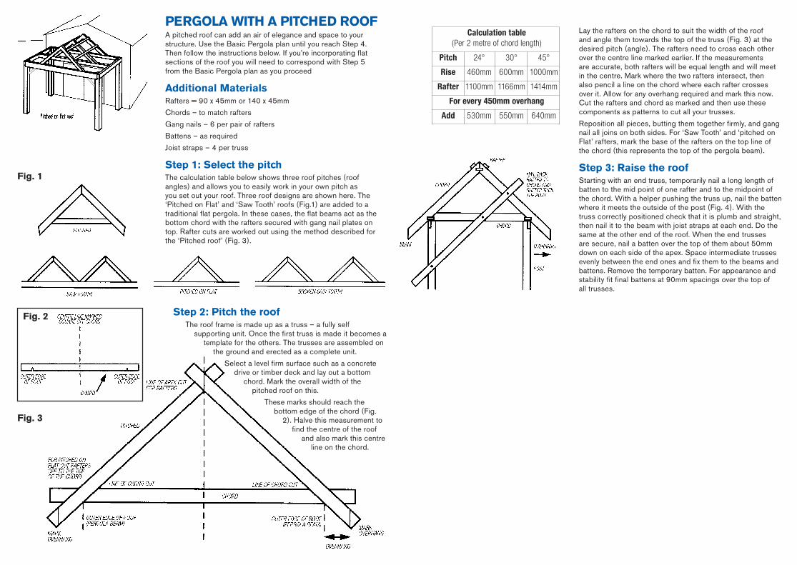
PERGOLA WITh A PITChED ROOfA pitched roof can add an air of elegance and space to your structure. Use the Basic Pergola plan until you reach Step 4. Then follow the instructions below. If you’re incorporating flat sections of the roof you will need to correspond with Step 5 from the Basic Pergola plan as you proceed
Additional MaterialsRafters = 90 x 45mm or 140 x 45mm
Chords – to match rafters
Gang nails – 6 per pair of rafters
Battens – as required
Joist straps – 4 per truss
Step 1: Select the pitchThe calculation table below shows three roof pitches (roof angles) and allows you to easily work in your own pitch as you set out your roof. Three roof designs are shown here. The ‘Pitched on Flat’ and ‘Saw Tooth’ roofs (Fig.1) are added to a traditional flat pergola. In these cases, the flat beams act as the bottom chord with the rafters secured with gang nail plates on top. Rafter cuts are worked out using the method described for the ‘Pitched roof’ (Fig. 3).
fig. 1
Calculation table (Per 2 metre of chord length)
Pitch 24° 30° 45°
Rise 460mm 600mm 1000mm
Rafter 1100mm 1166mm 1414mm
For every 450mm overhang
Add 530mm 550mm 640mm
Lay the rafters on the chord to suit the width of the roof and angle them towards the top of the truss (Fig. 3) at the desired pitch (angle). The rafters need to cross each other over the centre line marked earlier. If the measurements are accurate, both rafters will be equal length and will meet in the centre. Mark where the two rafters intersect, then also pencil a line on the chord where each rafter crosses over it. Allow for any overhang required and mark this now. Cut the rafters and chord as marked and then use these components as patterns to cut all your trusses.
Reposition all pieces, butting them together firmly, and gang nail all joins on both sides. For ‘Saw Tooth’ and ‘pitched on Flat’ rafters, mark the base of the rafters on the top line of the chord (this represents the top of the pergola beam).
Step 3: Raise the roofStarting with an end truss, temporarily nail a long length of batten to the mid point of one rafter and to the midpoint of the chord. With a helper pushing the truss up, nail the batten where it meets the outside of the post (Fig. 4). With the truss correctly positioned check that it is plumb and straight, then nail it to the beam with joist straps at each end. Do the same at the other end of the roof. When the end trusses are secure, nail a batten over the top of them about 50mm down on each side of the apex. Space intermediate trusses evenly between the end ones and fix them to the beams and battens. Remove the temporary batten. For appearance and stability fit final battens at 90mm spacings over the top of all trusses.
Step 2: Pitch the roofThe roof frame is made up as a truss – a fully self
supporting unit. Once the first truss is made it becomes a template for the others. The trusses are assembled on
the ground and erected as a complete unit.
Select a level firm surface such as a concrete drive or timber deck and lay out a bottom
chord. Mark the overall width of the pitched roof on this.
These marks should reach the bottom edge of the chord (Fig.
2). Halve this measurement to find the centre of the roof
and also mark this centre line on the chord.
fig. 3
fig. 2
M10773 MitrePlan #1.indd 8 3/3/09 9:11:36 AM
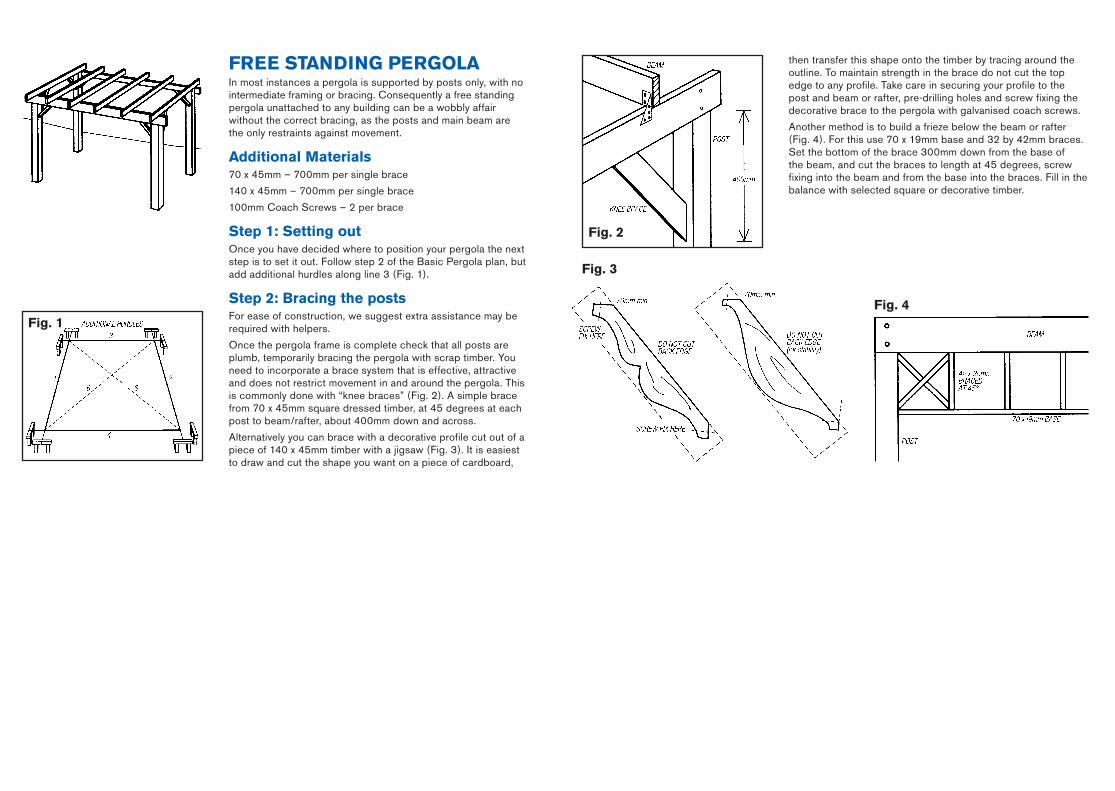
fREE STANDING PERGOLAIn most instances a pergola is supported by posts only, with no intermediate framing or bracing. Consequently a free standing pergola unattached to any building can be a wobbly affair without the correct bracing, as the posts and main beam are the only restraints against movement.
Additional Materials70 x 45mm – 700mm per single brace
140 x 45mm – 700mm per single brace
100mm Coach Screws – 2 per brace
Step 1: Setting outOnce you have decided where to position your pergola the next step is to set it out. Follow step 2 of the Basic Pergola plan, but add additional hurdles along line 3 (Fig. 1).
Step 2: bracing the postsFor ease of construction, we suggest extra assistance may be required with helpers.
Once the pergola frame is complete check that all posts are plumb, temporarily bracing the pergola with scrap timber. You need to incorporate a brace system that is effective, attractive and does not restrict movement in and around the pergola. This is commonly done with “knee braces” (Fig. 2). A simple brace from 70 x 45mm square dressed timber, at 45 degrees at each post to beam/rafter, about 400mm down and across.
Alternatively you can brace with a decorative profile cut out of a piece of 140 x 45mm timber with a jigsaw (Fig. 3). It is easiest to draw and cut the shape you want on a piece of cardboard,
fig. 3
fig. 4
fig. 2
fig. 1
then transfer this shape onto the timber by tracing around the outline. To maintain strength in the brace do not cut the top edge to any profile. Take care in securing your profile to the post and beam or rafter, pre-drilling holes and screw fixing the decorative brace to the pergola with galvanised coach screws.
Another method is to build a frieze below the beam or rafter (Fig. 4). For this use 70 x 19mm base and 32 by 42mm braces. Set the bottom of the brace 300mm down from the base of the beam, and cut the braces to length at 45 degrees, screw fixing into the beam and from the base into the braces. Fill in the balance with selected square or decorative timber.
M10773 MitrePlan #1.indd 9 3/3/09 9:11:37 AM
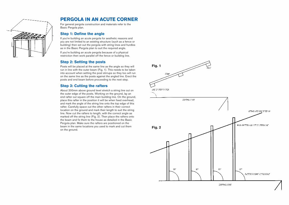
PERGOLA IN AN ACuTE CORNERFor general pergola construction and materials refer to the Basic Pergola plan.
Step 1: Define the angleIf you’re building an acute pergola for aesthetic reasons and you are not limited to an existing structure (such as a fence or building) then set out the pergola with string lines and hurdles as in the Basic Pergola plan to suit the required angle.
If you’re building an acute pergola because of a physical restriction then work parallel off the fence or building line.
Step 2: Setting the postsPosts will be placed at the same line as the angle so they will run in line with the outer beam (Fig. 1). This needs to be taken into account when setting the post stirrups so they too will run on the same line as the posts against the angled line. Erect the posts and end beam before proceeding to the next step.
Step 3: Cutting the raftersAbout 200mm above ground level stretch a string line out on the outer edge of the posts. Working on the ground, lay an end rafter out square off the main building line. On the ground, place this rafter in the position it will be when fixed overhead, and mark the angle of the string line onto the top edge of this rafter. Carefully space out the other rafters in their correct location on the ground and mark their length to suit the string line. Now cut the rafters to length, with the correct angle as marked off the string line (Fig. 2). Then place the rafters onto the beam and fix them to the house as detailed in the Basic Pergola plan. Make sure the rafters are positioned on the beam in the same locations you used to mark and cut them on the ground.
fig. 2
fig. 1
M10773 MitrePlan #1.indd 10 3/3/09 9:11:37 AM
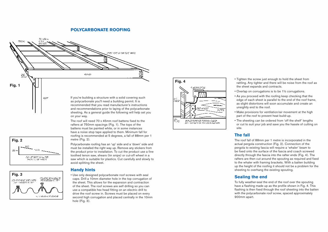
POLYCARbONATE ROOfING
If you’re building a structure with a solid covering such as polycarbonate you’ll need a building permit. It is recommended that you read manufacturer’s instructions and recommendations prior to laying of the polycarbonate sheeting. As a general guide the following will help set you on your way.
The roof will need 70 x 45mm roof battens fixed to the rafters at 750mm spacings (Fig. 1). The tops of the battens must be painted white, or in some instances have a noise stop tape applied to them. Minimum fall for roofing is recommended at 5 degrees, a fall of 88mm per 1 metre (Fig. 2).
Polycarbonate roofing has an ‘up’ side and a ‘down’ side and must be installed the right way up. Remove any stickers from the product prior to installation. To cut the product use a fine toothed tenon saw, shears (tin snips) or cut-off wheel in a saw which is suitable for plastics. Cut carefully and slowly to avoid splitting the sheet.
handy hints• Use only designed polycarbonate roof screws with seal
caps. Drill a 10mm diameter hole in the top corrugation of the sheet. This allows for the expansion and contraction of the sheet. The roof screws are self drilling so you can use a compatible hex head fitting on an electric drill to drive the roof screw in. Screws must be placed on every second high corrugation and placed centrally in the 10mm hole (Fig. 3).
fig. 3
fig. 2
fig. 1
• Tighten the screw just enough to hold the sheet from rattling. Any tighter and there will be noise from the roof as the sheet expands and contracts.
• Overlap on corrugations is to be 1½ corrugations.
• As you proceed with the roofing keep checking that the edge of each sheet is parallel to the end of the roof frame, as slight distortions will soon accumulate and create an unsightly end to the roof.
• Make provisions for ventilation/air movement at the high part of the roof to prevent heat build-up.
• The sheeting can be ordered from ‘off the shelf’ lengths or cut to suit your job and save you the hassle of cutting on site.
The fallThe roof fall of 88mm per 1 metre is incorporated in the actual pergola construction (Fig. 2). Connection of the pergola to existing fascia will require a ‘whaler’ beam to be fixed onto the surface of the fascia and coach screwed directly through the fascia into the rafter ends (Fig. 4). The rafters are then cut around the spouting as required and fixed to the whaler with framing brackets. With a batten building up the height of the roofing it should not be a problem for the sheeting to overhang the existing spouting.
Sealing the endTo fully weather-seal the end of the roof over the spouting have a flashing made up as the profile shown in Fig. 4. This flashing is then fixed through the roof sheeting into the batten with the polycarbonate roof screw, spaced approximately 900mm apart.
fig. 4
M10773 MitrePlan #1.indd 11 3/3/09 9:11:38 AM
• An easy-to-follow guide to achieving a perfect result. • Outlines all the tools you will need for the job.• Includes a materials checklist.
PLEASE NOTE: Before starting this project or buying any materials, it is worth your time to read all steps thoroughly first to be sure you understand what is required.
mitre10.com.auMitre 10 is proudly Australian owned.
MItrePlAn PrOJeCt PlAnner
93 16487 000 268
Your local MITRE 10 Store is:
IMPORTANT: This project planner has been produced to provide basic information and our experienced staff are available to answer any questions you may have. However, this information is provided for use on the understanding that Mitre 10 is not liable for any loss or damage which is suffered or incurred (including but not limited to indirect or consequential loss), for any personal injury or damage to property suffered or sustained as a result of using the information contained in this MitrePlan Project Planner. Mitre 10 advises you to call in a qualified tradesperson, such as an electrician or plumber, where expert services are required, and to independently assess any safety precautions that will need to be followed prior to using the information in this MitrePlan Project Planner.
WARNING: There may be by laws or regulations of councils or other statutory bodies that you must comply with when following this MitrePlan Project Planner.
Build a pergola
MIGhTY hELPfuL hINTS TO MAkE ThE jOb EASIER■ Building your pergola will be easier if you prepare all tools and materials first.
■ To weather-protect any timber that joins up against other sections of timber, stain or paint them first before fixing them together.
■ Measuring is easy, materials are expensive. Double check all measurements and markings before you cut any piece of timber.
■ When fixing the posts to the post supports use temporary props, fixed using nails or screws to hold the posts upright (while you drill the holes and fix them into place) to ensure they are perfectly vertical.
■ Weatherboards are not strong enough to support the structure, so be sure you fix the wall plate into the house studs.
■ If adding a solid cover, e.g. fibreglass roofing, make sure the height of the beam is slightly lower than the height of the wall plate to allow for water run-off.
■ A free-standing pergola can also be easily turned into a carport by adding a roof and stormwater run-off.
■ When using any power tool, your eyes should always be protected by wearing suitable goggles.
■ Remember a building permit may be required. Check with your council first about local regulations.
Build a pergola
#1
M10773 MitrePlan #1.indd 1 3/3/09 9:11:30 AM