Embed Size (px)
Citation preview

1
13th World Conference on Earthquake Engineering Vancouver, B.C., Canada
August 1-6, 2004 Paper No. 1622
MITIGATION OF RESIDUAL DISPLACEMENTS OF CIRCULAR REINFORCED CONCRETE BRIDGE COLUMNS
Junichi Sakai1 and Stephen A. Mahin2
SUMMARY A large ductility capacity is generally required of bridge columns located in regions of high seismicity to ensure economical designs with adequate protection against collapse. However, conventional bridge columns that develop high ductility demands tend to retain large permanent displacements. To maximize post-event operability and minimize repair costs, increased attention should be paid to reducing these residual displacements. To minimize residual displacements in reinforced concrete columns, a design is proposed whereby longitudinal post-tensioning strands replace some of usual longitudinal mild reinforcing bars. The seismic performance of such partially prestressed, reinforced concrete columns is investigated through a series of quasistatic and dynamic analyses. A series of quasistatic cyclic analyses is used to explore the effects of magnitude of prestressing force, amount of prestressing strands, and amount of longitudinal reinforcement on hysteretic behavior. For instance, when half of the longitudinal mild reinforcement in a conventional circular reinforced concrete column is replaced by an equal area of unbonded post-tensioning strand and a prestress equal to the axial force induced by the dead load is applied, the lateral force-lateral displacement relations for both columns are nearly identical, but the residual displacement (upon unloading that occurs from near the ultimate lateral displacement capacity) for the partially prestressed column is 86% smaller. Based on proportioning recommendations developed, four columns with different prestressing strand configurations are designed and analyzed dynamically. For the suite of near-fault ground motions considered, the post-tensioned columns exhibit maximum displacements similar to those for conventionally reinforced concrete designs, but residual displacements are reduced by more than 50% on average. Shaking table tests of moderate-scale cantilever specimens are underway to confirm these observations and design recommendations.
1 Postdoctoral Researcher, Pacific Earthquake Engineering Research Center, University of California at Berkeley, California, USA. Email: [email protected] 2 Byron and Elvira Nishkian Professor of Structural Engineering, Department of Civil and Environmental Engineering, University of California at Berkeley, California, USA. Email: [email protected]

2
INTRODUCTION
In recent years, a high ductility capacity is expected of bridge columns located in regions of high seismicity to ensure economical designs with adequate protection against collapse during strong ground shaking [1] [2]. It has been noted, however, that bridge columns that develop high ductility demands during extreme ground shaking are likely to retain large residual displacements following the earthquake. While a large residual displacement may not endanger overall safety, it can disrupt the flow of traffic and be costly and difficult to repair. To maximize post-event operability and minimize repair costs, attention should be paid in the design process to minimizing these residual displacements. Recent research in Japan has begun to explore methods for mitigating the post-earthquake residual displacement of reinforced concrete bridge columns [3] [4] [5]. These studies suggest that the use of prestressing tendons or unbonded high strength bars can reduce residual displacements. While results to date are promising, general recommendations have yet to be developed regarding the optimal characteristics of the column necessary to achieve desired seismic performance including reduced residual displacements. The research presented in this paper is part of a larger experimental and analytical investigation being conducted at the Pacific Earthquake Engineering Research Center to enhance the performance of reinforced concrete bridges. A new method for reducing residual displacements of reinforced concrete bridge columns has been developed whereby a single bundle of unbonded prestressing strand is incorporated at the center of the cross-section of a lightly reinforced concrete column [6]. This paper presents a series of quasistatic analyses for the reinforced concrete columns with unbonded prestressing strands to investigate the hysteretic response of such columns, followed by a series of dynamic analyses to validate the effectiveness of this approach in improving seismic performance.
BRIDGE COLUMN ANALYZED A circular, reinforced concrete column, designed in accordance with the Caltrans Seismic Design Criteria (SDC) [1], is considered in this study. This column is used as a reference for comparison with results obtained considering partially prestressed designs. Figure 1 illustrates the elevation and cross section of the reference column. The diameter of the column, D , is 1.83 m, and its height from the bottom of the column to the gravity center of the superstructure, h , is 10.97 m, resulting in an effective aspect ratio of 6. The dead load, P , supported by the column is taken as 4.5 MN. For an unconfined concrete strength, cof ′ ,
of 34.5 MPa, the axial load ratio, gco AfP ′ , is 5%. The conventionally designed column is reinforced
longitudinally with 48 No. 9 (29-mm diameter) deformed bars, providing for the standard case a longitudinal reinforcement ratio, lρ , of 1.18%. No. 5 (16-mm diameter) spirals are used to confine the
concrete core, spaced at a 76-mm pitch, resulting in a volumetric ratio, sρ , of 0.61%. Reinforcing bars
with a nominal yield strength of 420 MPa and an ultimate strain, suε , of 0.12 (Grade 60) are considered for both the longitudinal and spiral reinforcement. Based on the static push-over procedure suggested by the SDC, the computed lateral load capacity of the reference column is 1.29 MN and its yield and ultimate displacements are 0.11 m and 0.58 m, respectively. Based on findings by Sakai and Mahin [6], a partially prestressed, reinforced concrete column (see Fig. 2) with post-tensioning strand concentrated at the center of the cross-section and debonded from adjacent concrete over the full height of the column is believed to have desirable recentering characteristics under quasi-statically loading. Grade 270 strand is considered for the prestressing strands. The essentially elastic

3
prestressing steel strain, EE,psε , the ultimate strength, u,psf , and the ultimate strain, u,psε , are 0.0086,
1860 MPa and 0.03, respectively. To prevent undesirable premature crushing of concrete due to the additional axial load by the post-tensioning strands, additional confinement is provided for the partially prestressed columns. To enhance the confinement of the core concrete, the spiral pitch is reduced from 76 mm to 38 mm. Accordingly, the denser spirals increases sρ to 1.22%. As shown in Table 1, a series of quasistatic analyses is carried out systematically varying the following parameters: the magnitude of the prestressing force applied, psP , the areas of the strand and mild
reinforcement employed. For the purposes of this study, a prestressing force ratio, psα , and a strand ratio,
psρ , are defined as:
gco
psps Af
P
′=α ;
g
psps A
A=ρ (1)
where gA and psA are the gross cross-sectional area and the total area of the center post-tensioning
strands, respectively.
Table 1 Variables considered
Variables Values
Prestressing force ratio, psα 0%, 2.5%, 5%, 7.5%, 10% and 15%
Strand ratio, psρ 0.15%, 0.29%, 0.59% and 0.88%
Longitudinal reinforcement ratio, lρ 0.18%, 0.35%, 0.59% and 0.92%
FIG. 1. Conventionally designed reinforced FIG. 2. Partially prestressed column concrete column

4
ANALYTICAL MODEL The reference reinforced concrete bridge column and the partially prestressed columns are idealized as two-dimensional discrete models, as conceptually shown in Figs. 1 and 2. For sake of simplicity, the models are assumed fixed at the base and pinned at the top. The flexural hysteretic behavior of the plastic hinge region is idealized by a fiber element. The plastic hinge length is assumed to be 1.18 m, based on the equation proposed by Priestley et al. [7]. Rigid bars are used to model the footing and the region from the top of the column to the center of gravity of the superstructure. Linear beam elements with cracked stiffness properties are used for the remainder of the column. Post-tensioning strand that debonded from concrete is represented by a spring element spanning between assumed anchorage points. Figure 3 shows the stress-strain relation assumed for the core concrete. The confinement effect of concrete is evaluated based on the model developed by Mander et al. [8]. As sρ is varied from 0.61% to
1.22%, the core concrete strength, ccf ′ , the strain at peak stress, ccε , and the ultimate strain, cuε , increase from 42.4 MPa, 0.0043 and 0.014 to 49.3 MPa, 0.0063 and 0.021, respectively. Unloading and reloading paths are represented by the model proposed by Sakai and Kawashima [9]. The descending branch of the cover concrete is idealized as a linear function. Tensile stress of concrete is disregarded in this study. The envelope curves of longitudinal mild reinforcing bars and strands are idealized as a bilinear model. The initial modulus of elasticity, the yield strength and the strain-hardening ratio are equaled to 200 GPa, 414 MPa and 2% for the mild reinforcement; 196.5 GPa, 1800 MPa and 2% are used for the strands. The modified Menegotto-Pinto model proposed by Sakai and Kawashima [6] [10] is used to represent the hysteretic behavior of the rebar and the strands to take into account the Bauschinger effect. Predetermined cycles of displacement are imposed at the center of gravity of the superstructure. The amplitude in the first cycle is 0.127 m, which is almost the same as the yield displacement of the reference column. The lateral displacement is increased step wise up to 0.635 m, which is little over the estimated ultimate displacement of the column. The residual displacement, stard ⋅ , from the quasistatic cyclic analyses is defined here as the displacement at zero force following unloading from 0.635 m. This provides a general indication of the ability of the column to recenter following inelastic deformations. Later, a dynamic residual displacement is defined as the permanent displacement remaining after an earthquake excitation.
-0.03 -0.02 -0.01 0-60
-40
-20
0
Strain εc
( , )ε f cccc
εcu'
76 mm-pitch spirals38 mm-pitch spirals
Core concrete confined by
Str
ess
f c(M
Pa)
( , )ε f coco '
εspCover concrete
0
-0.8 0 0.8
Late
ral f
orce
(M
N)
-0.4 0.4Lateral displacement (m)
-1
1
2
-2
( , )F2d2( , )F5d5
( , )Fydy 00
dr sta.
FIG. 3. Confinement effect of spirals FIG. 4. Force-displacement hysteresis of reference column

5
QUASISTATIC BEHAVIOR OF COLUMNS
Reference reinforced concrete column Figure 4 shows the lateral force versus lateral displacement hysteresis of the reference reinforced concrete column. The column yields in the first cycle and the lateral force gradually increases with positive post-yield stiffness during subsequent cycles to larger lateral displacement. The first yield force, 0yF , is 0.89
MN, and the lateral force increases up to maxF = 1.44 MN at displacement of 0.635 m. The static residual
displacement, stard ⋅ , of the reference column is 0.434 m, 68% of the peak imposed displacement. The
accumulated energy dissipation through the cycles, DE , is 3.52 MNm. The computed post-yield tangent
lateral stiffness, 2K , is 0.48 MN/m, which is 3.9% of the initial stiffness, 1K . The initial and the post-yield stiffness is defined here as:
0
01
y
y
d
FK = ;
25
252 dd
FFK
−−= (2)
where 0yF and 0yd are the force and displacement, respectively, at the first yielding of a reinforcing bar,
2F and 2d are the force and displacement at the peak displacement in the second cycle, and 5F and 5d
are the force and displacement at the peak displacement in the fifth cycle. The skeleton curve (see Fig. 4) consists of lines with the initial stiffness from the origin and the post-yield stiffness through ( 2d , 2F ) and
( 5d , 5F ). The maximum compressive strain of the core concrete is 0.0145, which slightly exceeds the ultimate strain of concrete, cuε (equal to 0.014) at the maximum displacement. The maximum tensile strain of the
rebar is 0.06, 50 % of the ultimate tensile strain, suε (equal to 0.12). Reinforced concrete column with unbonded prestressing strand (Re-Centering RC column) For preliminary assessment of the effect of the use of unbonded prestressing strand, half of the longitudinal reinforcement (24 29-mm diameter (No. 9) bars) is removed, and a single bundle of prestressing strand, which has an area equivalent to 24 29-mm diameter bars, is arranged at the center of the cross section. A total post-tensioning force of 4.5 MN is applied, equivalent to the axial load due to the dead load. As a consequence, a total axial load of 0.1 gco AfP ′ is imposed. Thus, psα , psρ , and lρ of
this column are 5%, 0.59% and 0.59%, respectively. The denser spirals are used to prevent premature crushing of core concrete; the strand provided from the bottom of the footing to the top of the column is debonded from adjacent concrete by means of a duct. Such columns with unbonded prestressing strands are referred hereinafter as Re-Centering RC columns. Figure 5 compares the hystereses between the conventional design and the Re-Centering RC column. The initial stiffness of the Re-Centering column is similar to that of the reference column. After yielding, the force steadily increases with the positive post-yield stiffness, reaching a maximum strength of 1.44 MN; the skeleton curve is nearly identical to that of the RC column. The use of unbonded prestressing strand significantly reduces the residual displacement upon unloading from a peak displacement. The residual displacement in the fifth cycle is 0.061 m, only 14% of the RC column. The peak strain of the strand is 0.0035, 40% of EE,psε . The maximum core concrete strain increases up to 0.018; however this is still
14% smaller than the ultimate strain of the concrete confined by the denser spirals. The maximum tensile strain of the rebar is 0.057.

6
0
-0.8 0 0.8
Re-Centering columnRC column
Late
ral f
orce
(M
N)
-0.4 0.4Lateral displacement (m)
-1
1
2
-2
0
0 0.015
2000
Strain psε0.010.005
1000
Str
ess
f ps
(MP
a)
εps,EE
Re-Centering column
(a) Force-displacement hystereses (b) Stress-strain hystereses of prestressing strand
-60
0
-0.03 0
-20
-0.01
-40
Strain ε c
εcu
Str
ess
f c(M
Pa)
-0.02
-800
0
800
0 0.08
400
-400
Strain sε-0.04 0.04
Str
ess
f s(M
Pa)
(c) Stress-strain hystereses of core concrete (d) Stress-strain hystereses of rebar
FIG. 5. Quasistatic behavior of Re-Centering RC column Effect of magnitude of prestressing force Figure 6 shows the sensitivity of hysteretic behavior of the columns to the magnitude of post-tensioning force. Here, psρ and lρ are fixed at 0.59% and 0.59%, respectively. Cases of psα = 0%, 5%, 10% and
15% are shown in Fig. 6 (a). The reference column is also shown for comparison. When the prestressing force increases by increasing the initial stress in the strand, both the first yield strength and the maximum lateral force increase. The residual displacement of the Re-Centering columns is smaller than 20% of that of the reference column except for the column without prestressing force. To evaluate the quasistatic performance of Re-Centering RC columns, the ratios of the values of the quasistatic residual displacement, the first yield force, the flexural strength, the post-yield stiffness and the total energy dissipation between the reference column and the Re-Centering columns are computed. The maximum compressive concrete and tensile rebar strains are expressed as a percentage of the appropriate ultimate values, cuε and suε . The maximum tensile strand strain is divided by the essentially elastic
strain EE,psε . Figure 6 (b) shows the effect of varying the magnitude of prestressing force on the values
described above. The quasistatic residual displacement decreases when, psα increases from 0% to 7.5%,
and then increases as psα increases above 7.5% due to the crushing of the core concrete that occurs at

7
large displacements for these prestress levels. As psα increase, the first yield force and the maximum
strength increase as described above, but the post-yield stiffness decrease. The total energy dissipation does not significantly depend on the magnitude of the prestressing force. Figure 6 (b) suggests the maximum core concrete strain exceeds the ultimate concrete strain when psα exceeds 10%. As expected,
the peak strain in the post-tensioning strand increases when psα increases. Nonetheless, the strand does
not yield, even when psα reaches 20%.
0
0
Late
ral f
orce
(M
N)
-1
1
2
-2
α ps
15%
5%0%
10%
RC
-0.3 0.3-0.6 0.6Lateral displacement (m)
0
100
200
0 5 10 15 20
Rat
io (
%) 150
50
Residual displacementMaximum lateral force
Post-yield stiffnessEnergy dissipation
First yield force
Prestressing force 0 5 10 15 20
Core concrete strain/Steel strain/Strand strain/
εcuεsu
εps, EE
ratio (%)α ps (a) Force-displacement hystereses (b) Dependence on magnitude of prestressing force
FIG. 6. Effect of magnitude of prestressing force Effect of amount of prestressing strand provided The area of strand provided does not significantly affect the hysteretic behavior of the column for a constant prestressing force, as shown in Fig. 7, where psα = 5% and lρ = 0.59%. This figure suggests
that varying the area of strand is effective means of controlling the post-yield stiffness. However, the strain in the core concrete and in the post-tensioning strand should be carefully reviewed, because the concrete strain increases as the area of strand increases, and the strand are likely to yield when psρ becomes
sufficiently small.
0
0
ρps
0.88%
0.29%0.15%
0.59%
RC
Late
ral f
orce
(M
N)
-1
1
2
-2-0.3 0.3
Lateral displacement (m)-0.6 0.6
0
100
200
0 0.2 0.4 0.6 0.8 1
Rat
io (
%) 150
50
Strand ratio (%)ρps
Residual displacementMaximum lateral force
Post-yield stiffnessEnergy dissipation
First yield force
0 0.2 0.4 0.6 0.8 1Strand ratio (%)ρps
1
Core concrete strain/Steel strain/Strand strain/
εcuεsu
εps, EE
(a) Force-displacement hystereses (b) Dependence on amount of strand
FIG. 7. Effect of amount of post-tensioning strand

8
Effect of area of longitudinal mild reinforcing bars Figure 8 shows the effect of the area of longitudinal reinforcing bars on the behavior of the columns. Here, psα and psρ are 5% and 0.59%, respectively. The residual displacement, the flexural strength, the
first yield force, the post-yield stiffness, and the capacity of energy dissipation increase with increasing
lρ . Smaller lρ is preferable, because it results in smaller residual displacement; however, it also leads to smaller flexural strength and energy dissipation capacity. Smaller flexural strength and energy dissipation may increase seismic demand. Therefore, the appropriate amount of longitudinal rebar should be determined based on dynamic analyses.
0
0
ρ l
0.92%
0.35%0.18%
0.59%
RC
Late
ral f
orce
(M
N)
-1
1
2
-2-0.3 0.3-0.6 0.6
Lateral displacement (m)
0
100
200
0 0.2 0.4 0.6 0.8 1
Rat
io (
%) 150
50
Longitudinal reinforcement
Residual displacementMaximum lateral force
Post-yield stiffnessEnergy dissipation
First yield force
0 0.2 0.4 0.6 0.8 1 ratio (%)ρ
l
1
Core concrete strain/Steel strain/Strand strain/
εcuεsu
εps, EE
(a) Force-displacement hystereses (b) Dependence on amount of longitudinal mild reinforcement
FIG. 8. Effect of amount of longitudinal mild reinforcement
DYNAMIC RESPONSE OF BRIDGES SUPPORTED BY RE-CENTERING RC COLUMNS Selection of Re-Centering RC columns for analyses To assess the dynamic performance of Re-Centering RC columns, several columns are subjected to an ensemble of earthquake ground motions. To select the columns used in the dynamic analyses, additional quasistatic analyses are conducted to identify specific combinations of design parameters where the columns have skeleton loading characteristics similar to the reference column, exhibit origin-oriented hysteretic properties upon unloading, and avoid excessive strains in the materials. Design variables considered are the magnitude of the prestressing force, the area of the post-tensioning strands, and the area of the longitudinal rebars. The quasistatic analyses demonstrates that (1) a prestressing force ratio, psα , between 5% and 10% are
seen to be preferable; (2) the strand ratio, psρ , can be taken from 0.15% to 0.88%, depending on the
combination with psρ and lρ , but the total steel ratio, psρ + lρ , should be larger than about 0.7%; (3)
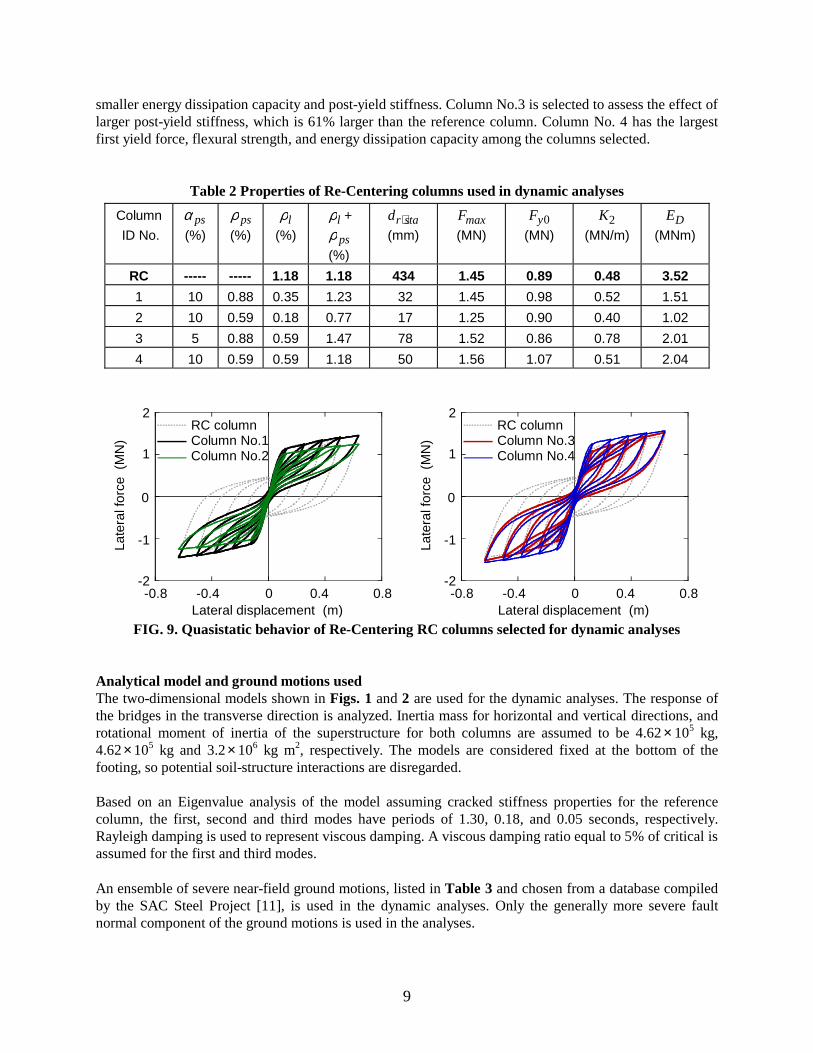
the longitudinal reinforcement ratio, lρ , cannot be larger than 0.59%, because increasing the amount of the longitudinal rebar results in a relatively large residual displacement. Based on these findings, four columns shown in Table 2 and Figure 9 are selected. Column No.1 has almost the same skeleton curve as the reference column. Column No.2, which develops the smallest quasistatic residual displacement among the columns selected, is selected to determine the effect of
9
smaller energy dissipation capacity and post-yield stiffness. Column No.3 is selected to assess the effect of larger post-yield stiffness, which is 61% larger than the reference column. Column No. 4 has the largest first yield force, flexural strength, and energy dissipation capacity among the columns selected.
Table 2 Properties of Re-Centering columns used in dynamic analyses
Column
ID No. psα
(%) psρ
(%) lρ
(%) lρ +
psρ
(%)
stard ⋅
(mm) maxF
(MN) 0yF
(MN) 2K
(MN/m) DE
(MNm)
RC ----- ----- 1.18 1.18 434 1.45 0.89 0.48 3.52
1 10 0.88 0.35 1.23 32 1.45 0.98 0.52 1.51
2 10 0.59 0.18 0.77 17 1.25 0.90 0.40 1.02
3 5 0.88 0.59 1.47 78 1.52 0.86 0.78 2.01
4 10 0.59 0.59 1.18 50 1.56 1.07 0.51 2.04
0
-0.8 0 0.8
RC columnColumn No.1Column No.2
Late
ral f
orce
(M
N)
-0.4 0.4Lateral displacement (m)
-1
1
2
-2
0
-0.8 0 0.8
RC columnColumn No.3Column No.4
Late
ral f
orce
(M
N)
-0.4 0.4Lateral displacement (m)
-1
1
2
-2
FIG. 9. Quasistatic behavior of Re-Centering RC columns selected for dynamic analyses
Analytical model and ground motions used The two-dimensional models shown in Figs. 1 and 2 are used for the dynamic analyses. The response of the bridges in the transverse direction is analyzed. Inertia mass for horizontal and vertical directions, and rotational moment of inertia of the superstructure for both columns are assumed to be 4.62 × 10⁵ kg, 4.62×10⁵ kg and 3.2× 10⁶ kg m2, respectively. The models are considered fixed at the bottom of the footing, so potential soil-structure interactions are disregarded. Based on an Eigenvalue analysis of the model assuming cracked stiffness properties for the reference column, the first, second and third modes have periods of 1.30, 0.18, and 0.05 seconds, respectively. Rayleigh damping is used to represent viscous damping. A viscous damping ratio equal to 5% of critical is assumed for the first and third modes. An ensemble of severe near-field ground motions, listed in Table 3 and chosen from a database compiled by the SAC Steel Project [11], is used in the dynamic analyses. Only the generally more severe fault normal component of the ground motions is used in the analyses.

10
Table 3 Near-field earthquake ground motion records considered
Record Earthquake Magnitude Epicentral PGA (m/sec2)
Distance Normal Parallel
Tabas Tabas, Iran, 1978 7.4 1.2 km 8.83 9.59
Los Gatos Loma Prieta, USA, 1989 7.0 3.5 km 7.04 4.49
Lexington Dam Loma Prieta, USA, 1989 7.0 6.3 km 6.73 3.63
Petrolia Cape Mendocino, USA, 1992 7.1 8.5 km 6.26 6.42
Erzincan Erzincan, Turkey, 1992 6.7 2.0 km 4.24 4.48
Landers Landers, USA, 1992 7.3 1.1 km 7.00 7.84
Rinaldi Northridge, USA, 1994 6.7 7.5 km 8.73 3.81
Olive View Northridge, USA, 1994 6.7 6.4 km 7.18 5.84
JMA Kobe Hyogo-ken Nanbu, Japan, 1995 6.9 3.4 km 10.67 5.64
Takatori Hyogo-ken Nanbu, Japan, 1995 6.9 4.3 km 7.71 4.16
0
0 5 10 15 20
5
10
-5
-10
Time (sec)
Acc
eler
atio
n (m
/sec
)2
0
0 5 10 15 20Acc
eler
atio
n (m
/sec
)3
6
-3
-6
2
Time (sec)
RC
No. 1No. 2
No. 3No. 4
Re-Centering Columns
(a) Ground motion (Lexington Dam record) (b) Response acceleration at deck
0
0 5 10 15 20
Dis
plac
emen
t (m
)
0.3
0.6
-0.3
-0.6
Time (sec)
RC
Re-Centering Columns
0
0
Late
ral f
orce
(MN
)
-0.3 0.3Lateral displacement (m)
-1
1
2
-2
Mh
-0.6 0.6
(c) Response displacement at deck (d) Force-displacement hystereses
FIG. 10. Dynamic response of columns subjected to Lexington Dam record Dynamic response Figure 10 compares the dynamic response of the bridges supported by the Re-Centering RC columns and the reference column subjected to the Lexington Dam record obtained during 1989 Loma Prieta, California, earthquake. To draw force-displacement hystereses, the lateral force at the center of gravity of

11
the superstructure is obtained by dividing the bending moment at the bottom of the column, M , by the height from the top of the foundation to the center of gravity of the superstructure, h . The maximum response accelerations of the reference column is 4.8 m/sec2, while those of the Re-Centering Columns are 4.4~5 m/sec2. All the columns have nearly the same force-displacement characteristics when moving away from the origin as expected. The reference column has the smallest response displacement, while Column No. 4 has the largest, which is 18% larger than the reference column. The pronounced origin-oriented nature of the hysteretic loops of the Re-Centering Columns upon unloading can be clearly seen in Fig. 10 (d). Figure 11 compares the maximum and the residual displacements for all ten ground motions. The ultimate displacement of the reference column is also shown in Fig. 11 (a). As a whole, the maximum responses of the Re-Centering RC columns are almost the same as that predicted for the reference column. Because of the high intensity of the ground motions considered, two of the records (Los Gatos and Takatori) cause the response to exceed the ultimate displacement capacity. Relatively large residual displacements are produced in the reference column for the Lexington Dam and Petrolia records. In contrast, the residual displacements of nearly all of the Re-Centering columns are considerably smaller than that of the reference column, with Column 3 having the smallest residual displacement. The exception is Columns No. 1 and 4 subjected to the Takatori record, where the earthquake resulted in crushing of the confined concrete core in the analyses. Relatively small energy dissipation capacity and post-yield stiffness (Column No. 2) results in relatively large maximum response than the other Re-Centering columns although the residual displacements are about the same as the others. On the other hand, Column No. 3 performs the best overall, which has relatively large post-yield stiffness, and develops 5-10% smaller maximum displacements and 30-50% smaller residual displacements than the other Re-Centering columns.
0
0.2
0.4
0.6
0.8
1
Max
imum
dis
plac
emen
t (m
)
Tab
as
Los
Gat
os
Lex.
Dam
Pet
rolia
Land
ers
Oliv
e V
iew
JMA
Kob
e
Tak
ator
i
Erz
inca
n
Rin
aldi
RCNo. 1 No. 2 No. 4
Ultimate Displacement
Re-Centering ColumnsNo. 3
0
0.02
0.04
0.06
Res
idua
l dis
plac
emen
t (m
)
Tab
as
Los
Gat
os
Lex.
Dam
Pet
rolia
Land
ers
Oliv
e V
iew
JMA
Kob
e
Tak
ator
i
Erz
inca
n
Rin
aldi
(a) Maximum displacements (b) Residual displacements
FIG. 11. Maximum and residual displacements for 10 near-field ground motions

12
EARTHQUAKE SIMULATION TEST FOR RE-CENTERING COLUMNS
To assess the ability of these analytical models to predict response and investigate the effect of multi-directional loading and P-delta effects, several shaking table experiments are being carried out at Berkeley. The first two specimens have been prepared. These represent simple cantilever columns like those analyzed in this paper. The specimens are approximately 1/4-scale models. One specimen is a conventional reinforced concrete specimen, while the other is a Re-centering RC column. Details of the re-centering column specimen are shown in Fig. 12. Comparison of the two tests with one another and with computer predictions of response will provide many suggestions for future research to enhance the performance of bridge structures.
(a) Specimen on shaking table (b) Details of Re-Centering column model
FIG. 12. Shaking table tests
CONCLUSIONS To validate the effectiveness of providing unbonded prestressing strands in reinforced concrete columns on reducing residual displacements, a series of dynamic analyses as well as quasistatic analyses is conducted. Below are the conclusions determined from these analyses: (1) Replacing half of the longitudinal mild reinforcement with unbonded strand and applying a
prestressing force equal to the axial force induced by the dead load results in 86% reduction of residual displacement when unloaded from near the ultimate displacement capacity. The restoring force characteristics of the column with unbonded prestressing strand is virtually identical to that of the conventionally designed reinforced concrete column during loading;
(2) Results from quasistatic analyses demonstrate that prestressing force ratios between 5% and 10% are preferable. The post-yield stiffness of the Re-Centering RC column can be controlled by varying the area of post-tensioning strand incorporated into the column. Smaller amount of longitudinal mild reinforcement is preferable for reducing quasistatic residual displacement; and
13
(3) Columns with unbonded prestressing strands (Re-Centering RC columns) perform very well under strong ground shaking. A column with larger post-yield stiffness shows better performance for both the residual and maximum displacements.
ACKNOWLEDGEMENTS
The first author is grateful to the Japan Society for the Promotion of Science (JSPS) for its support of this research. This work was also supported by the Earthquake Engineering Research Centers program of the National Science Foundation (NSF) under Award number EEC-9701568 through the Pacific Earthquake Engineering Research Center (PEER). Any opinions, findings and conclusions or recommendations expressed in this paper are those of the authors and do not necessarily reflect those of NSF or JSPS.
REFERENCES 1. California Department of Transportation Seismic design criteria Ver. 1.2 California, 2001. 2. Japan Road Association Specifications for highway bridges. Part V: Seismic design Japan, 2000. 3. Ikeda, S. "Seismic behavior of reinforced concrete columns and improvement by vertical
prestressing." Challenges for Concrete in the Next Millennium, Proc. of XIIIth FIP Congress, Vol. 1, Balkema Rotterdam, Netherlands, 1998: 879-884.
4. Zatar, W. A. and Mutsuyoshi, H. "Reduced residual displacements of partially prestressed concrete bridge piers." Proc. of 12th World Conference on Earthquake Engineering, Auckland, New Zealand. Paper no. 1111. New Zealand Society for Earthquake Engineering, 2000.
5. Iemura, H., Takahashi, Y. and Sogabe, N. "Innovation of high-performance RC structure with unbonded bars for strong earthquakes." J. Struc. Mech. Earthq. Engrg. 2002, Japan Society of Civil Engineers; No. 710/I-60: 283-296 (in Japanese).
6. Sakai, J. and Mahin, S. A. "Analytical investigations of new methods for reducing residual displacements of reinforced concrete bridge columns." Pacific Earthquake Engineering Research Report, PEER-2004-**, Univ. of California at Berkeley (submitted for publication).
7. Priestley, M. J. N., Seible, F. and Calvi, G. M. Seismic Design and Retrofit of Bridges John Wiley & Sons, Inc., 1996.
8. Mander, J. B., Priestley, M. J. N. and Park, R. "Theoretical stress-strain model for confined concrete." J. Struct. Engrg. 1988, ASCE; 114(8): 1804-1826.
9. Sakai, J. and Kawashima, K. "Unloading and reloading stress-strain model for confined concrete." J. Struct. Engrg., ASCE (submitted for publication).
10. Sakai, J. and Kawashima, K. "Modification of the Giuffre, Menegotto and Pinto model for unloading and reloading paths with small strain variations." J. Struc. Mech. Earthq. Engrg. 2003, Japan Society of Civil Engineers; No. 738/I-64: 159-169 (in Japanese).
11. Somerville, P., Smith, N. Punyamurthula, S. and Sun, J. "Development of ground motion time histories for phase 2 of the FEMA/SAC steel project." Report No. SAC/BD-97/04, SAC Joint Venture, 1997.