Embed Size (px)
Citation preview
Mitigation of Fiber-Weave Effects by Broadside Coupled Differential Striplines
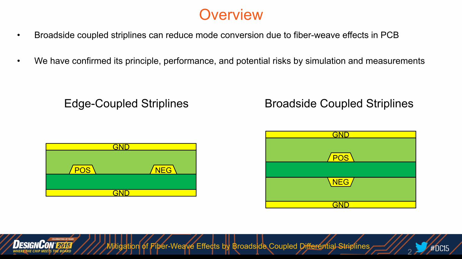
Overview• Broadside coupled striplines can reduce mode conversion due to fiber-weave effects in PCB
• We have confirmed its principle, performance, and potential risks by simulation and measurements
POS
GND
GND
NEGPOS
GND
GND
NEG
Edge-Coupled Striplines Broadside Coupled Striplines
2Mitigation of Fiber-Weave Effects by Broadside Coupled Differential Striplines
Outline• Background• Principles• Implementation Issues• Evaluation Results• Summary
3Mitigation of Fiber-Weave Effects by Broadside Coupled Differential Striplines
Outline• Background• Principles• Implementation Issues• Evaluation Results• Summary
4Mitigation of Fiber-Weave Effects by Broadside Coupled Differential Striplines
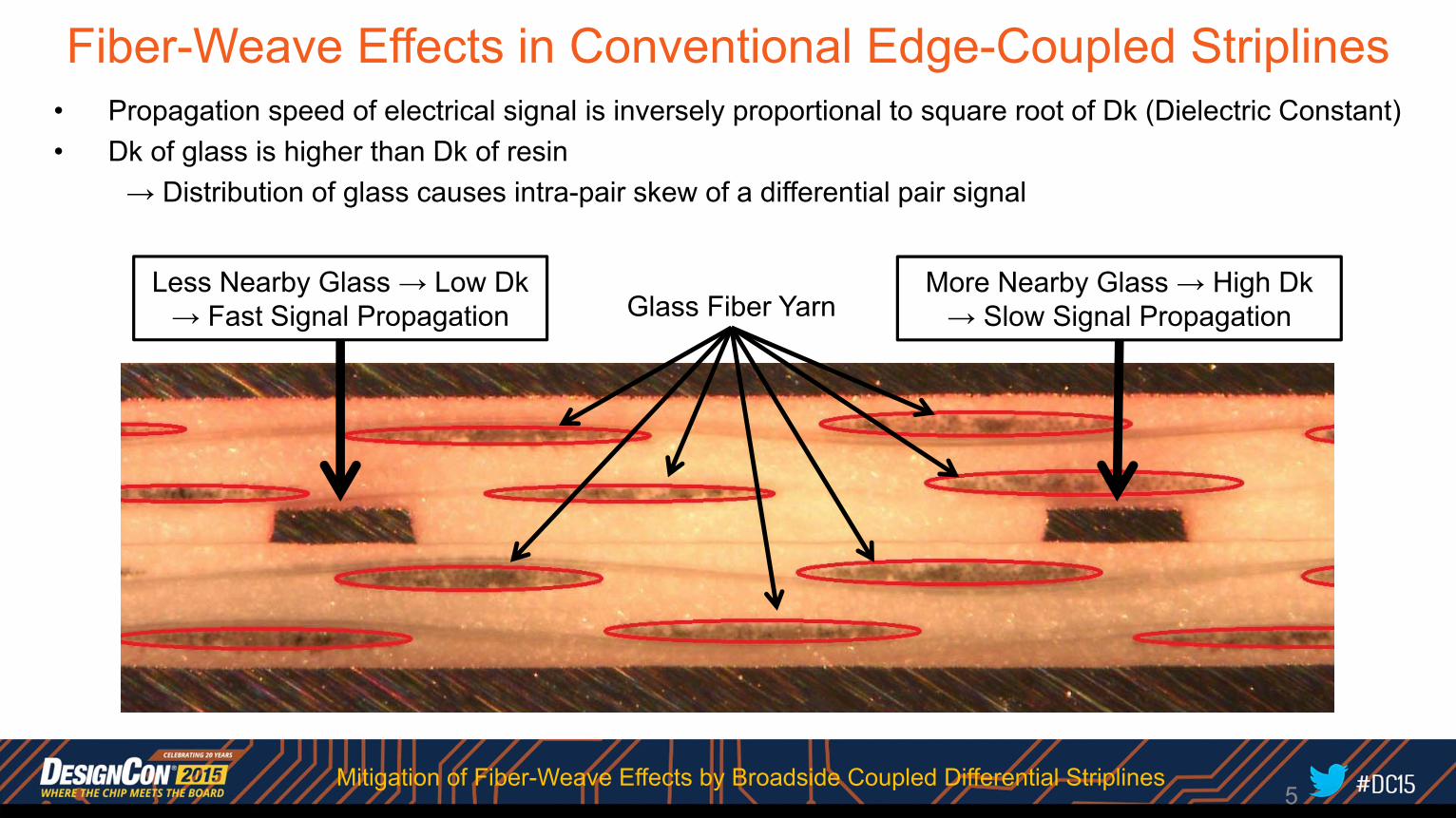
Fiber-Weave Effects in Conventional Edge-Coupled Striplines• Propagation speed of electrical signal is inversely proportional to square root of Dk (Dielectric Constant)• Dk of glass is higher than Dk of resin
→ Distribution of glass causes intra-pair skew of a differential pair signal
More Nearby Glass → High Dk→ Slow Signal PropagationGlass Fiber Yarn
Less Nearby Glass → Low Dk→ Fast Signal Propagation
5Mitigation of Fiber-Weave Effects by Broadside Coupled Differential Striplines
Intra-pair Skew and Mode Conversion
6
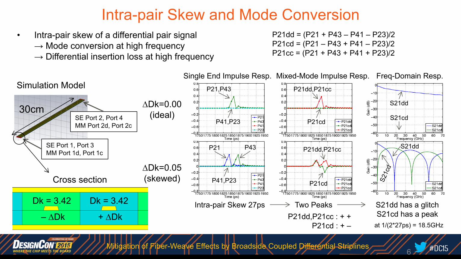
• Intra-pair skew of a differential pair signal→ Mode conversion at high frequency→ Differential insertion loss at high frequency
P21dd = (P21 + P43 – P41 – P23)/2P21cd = (P21 – P43 + P41 – P23)/2P21cc = (P21 + P43 + P41 + P23)/2
P21 P43 S21dd
Single End Impulse Resp. Mixed-Mode Impulse Resp. Freq-Domain Resp.
Dk = 3.42
– Dk
Cross section
30cm
Simulation Model
SE Port 2, Port 4MM Port 2d, Port 2c
SE Port 1, Port 3MM Port 1d, Port 1c
Dk=0.00(ideal)
Dk=0.05(skewed)
P21,P43
P41,P23
S21dd
S21cd
P21dd,P21cc
P21cd
P41,P23
P21dd,P21cc
P21cd
Dk = 3.42
+ DkIntra-pair Skew 27ps S21dd has a glitch
S21cd has a peakTwo Peaks
P21dd,P21cc : + +P21cd : + – at 1/(2*27ps) = 18.5GHz
Mitigation of Fiber-Weave Effects by Broadside Coupled Differential Striplines
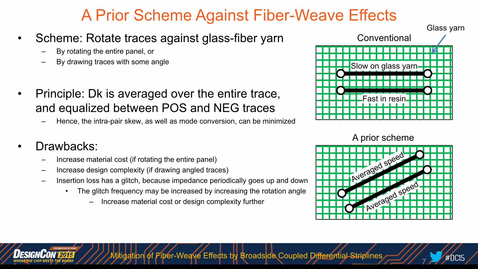
A Prior Scheme Against Fiber-Weave Effects• Scheme: Rotate traces against glass-fiber yarn
– By rotating the entire panel, or– By drawing traces with some angle
• Principle: Dk is averaged over the entire trace,and equalized between POS and NEG traces
– Hence, the intra-pair skew, as well as mode conversion, can be minimized
• Drawbacks:– Increase material cost (if rotating the entire panel)– Increase design complexity (if drawing angled traces)– Insertion loss has a glitch, because impedance periodically goes up and down
• The glitch frequency may be increased by increasing the rotation angle– Increase material cost or design complexity further
Conventional
A prior scheme
Glass yarn
Slow on glass yarn
Fast in resin
7Mitigation of Fiber-Weave Effects by Broadside Coupled Differential Striplines

Outline• Background• Principles• Implementation Issues• Evaluation Results• Summary
8Mitigation of Fiber-Weave Effects by Broadside Coupled Differential Striplines
GND
GND
GND
GND
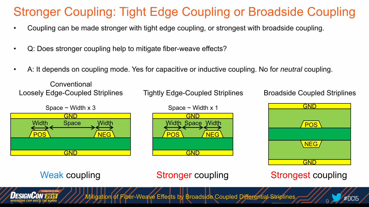
Stronger Coupling: Tight Edge Coupling or Broadside Coupling• Coupling can be made stronger with tight edge coupling, or strongest with broadside coupling.
• Q: Does stronger coupling help to mitigate fiber-weave effects?
• A: It depends on coupling mode. Yes for capacitive or inductive coupling. No for neutral coupling.
POS
GND
GND
NEGPOS
NEG
ConventionalLoosely Edge-Coupled Striplines Broadside Coupled Striplines
POS NEG
Tightly Edge-Coupled Striplines
9
Space ~ Width x 3 Space ~ Width x 1
Width Space Width Width WidthSpace
Weak coupling Stronger coupling Strongest coupling
Mitigation of Fiber-Weave Effects by Broadside Coupled Differential Striplines
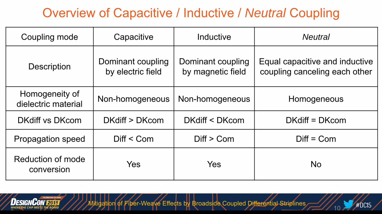
Overview of Capacitive / Inductive / Neutral Coupling
10
Coupling mode Capacitive Inductive Neutral
Description Dominant coupling by electric field
Dominant coupling by magnetic field
Equal capacitive and inductive coupling canceling each other
Homogeneity of dielectric material Non-homogeneous Non-homogeneous Homogeneous
DKdiff vs DKcom DKdiff > DKcom DKdiff < DKcom DKdiff = DKcom
Propagation speed Diff < Com Diff > Com Diff = Com
Reduction of mode conversion Yes Yes No
Mitigation of Fiber-Weave Effects by Broadside Coupled Differential Striplines
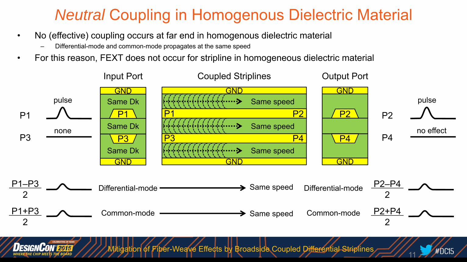
Neutral Coupling in Homogenous Dielectric Material• No (effective) coupling occurs at far end in homogenous dielectric material
– Differential-mode and common-mode propagates at the same speed
• For this reason, FEXT does not occur for stripline in homogeneous dielectric material
Input Port
P1+P3 2
P1–P3 2
Output PortGND
GND
P1
P3
GND
GND
P2
P4
P2+P4 2
P2–P4 2
Coupled StriplinesGND
GND
P1
P3
P2
P4
Differential-mode
Common-mode
Same speed
Same speed
Same Dk
Same Dk
Same Dk Same speed
Same speed
Same speedpulse
none
pulse
no effect
P1
P3
P2
P4
Differential-mode
Common-mode
11Mitigation of Fiber-Weave Effects by Broadside Coupled Differential Striplines
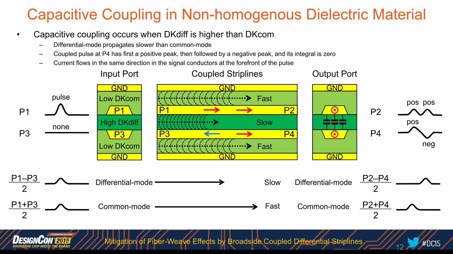
Capacitive Coupling in Non-homogenous Dielectric Material• Capacitive coupling occurs when DKdiff is higher than DKcom
– Differential-mode propagates slower than common-mode– Coupled pulse at P4 has first a positive peak, then followed by a negative peak, and its integral is zero– Current flows in the same direction in the signal conductors at the forefront of the pulse
P1
P3
Input Port
P2
P4
P1+P3 2
P1–P3 2
Output PortGND
GND
P1
P3
GND
GND
P2+P4 2
P2–P4 2
Coupled StriplinesGND
GND
P1
P3
P2
P4
Differential-mode
Common-mode
Low DKcom
High DKdiff
Low DKcom
pulse
none Slow
Fast
Fast neg
pos
Fast
Slow Differential-mode
Common-mode
12
pos pos
Mitigation of Fiber-Weave Effects by Broadside Coupled Differential Striplines
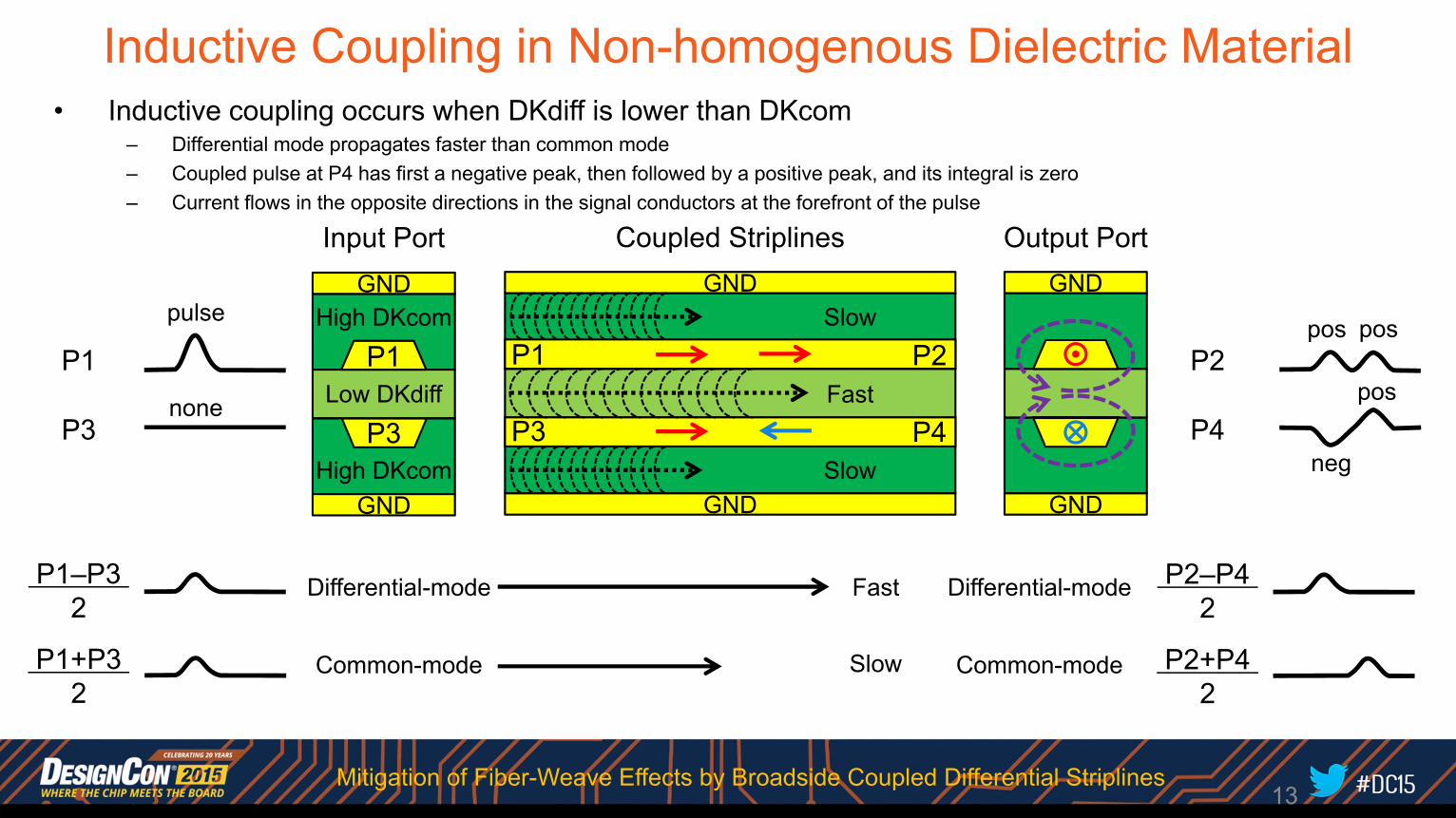
Inductive Coupling in Non-homogenous Dielectric Material• Inductive coupling occurs when DKdiff is lower than DKcom
– Differential mode propagates faster than common mode– Coupled pulse at P4 has first a negative peak, then followed by a positive peak, and its integral is zero– Current flows in the opposite directions in the signal conductors at the forefront of the pulse
Input Port
P1+P3 2
P1–P3 2
Output PortGND
GND
P1
P3
GND
GND
P2+P4 2
P2–P4 2
Coupled StriplinesGND
GND
P1
P3
P2
P4
Differential-mode
Common-mode
High DKcom
Low DKdiff
High DKcom Slow
Fast
Slowpulse
none
neg
posP1
P3
P2
P4
Slow
Fast Differential-mode
Common-mode
13
pos pos
Mitigation of Fiber-Weave Effects by Broadside Coupled Differential Striplines

–0.05
+0.05
±0.00
+0.05 +0.05
–0.05 –0.05
–0.05
+0.05
±0.00
+0.05 +0.05
–0.05 –0.05
DK1=3.42
DK2=3.42
DK2=3.42
Larger P41, P23Separated peaks
Smaller P21cdSeparated peaks
Larger inter-mode skew
Reduced S21cd gainReduced S21cd freq.
DK1=3.42
DK2=3.32
DK2=3.32
DK1=3.42
DK2=3.22
DK2=3.22
SE Impulse Response MM Impulse Response Frequency-Domain ResponseReduction of Mode Conversion by Capacitive Coupling
NeutralDK1 = DK2
StrongCapacitive
DK1 >> DK2
CapacitiveDK1 > DK2
P21 P43
P41,P23
P21cc
P21cd
S21dd
S21cd
P21dd
14
P21 P43
P41,P23
P21 P43
P41,P23
P21cc
P21cd
P21dd
P21cd
P21dd,P21cc
S21dd
S21cd
S21dd
S21cd
P21dd = (P21 + P43 – P41 – P23)/2P21cd = (P21 – P43 + P41 – P23)/2P21cc = (P21 + P43 + P41 + P23)/2
–0.05
+0.05
±0.00
+0.05 +0.05
–0.05 –0.05
Mitigation of Fiber-Weave Effects by Broadside Coupled Differential Striplines
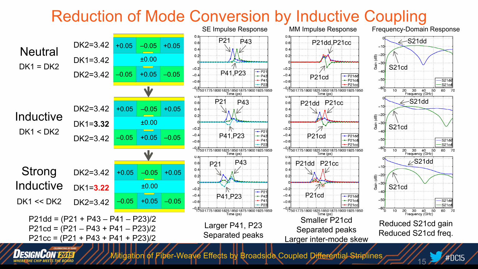
NeutralDK1 = DK2
SE Impulse Response MM Impulse Response Frequency-Domain Response
Larger P41, P23Separated peaks
Smaller P21cdSeparated peaks
Larger inter-mode skew
Reduced S21cd gainReduced S21cd freq.
StrongInductiveDK1 << DK2
InductiveDK1 < DK2
Reduction of Mode Conversion by Inductive Coupling
15
P21 P43
P41,P23
P21dd
P21cd
S21dd
S21cd
P21cc
P21 P43
P41,P23
P21 P43
P41,P23
P21dd
P21cd
P21cc
P21cd
P21dd,P21cc
S21dd
S21cd
S21dd
S21cd
P21dd = (P21 + P43 – P41 – P23)/2P21cd = (P21 – P43 + P41 – P23)/2P21cc = (P21 + P43 + P41 + P23)/2
–0.05
+0.05
±0.00
+0.05 +0.05
–0.05 –0.05
–0.05
+0.05
±0.00
+0.05 +0.05
–0.05 –0.05
DK1=3.42
DK2=3.42
DK2=3.42
DK1=3.32
DK2=3.42
DK2=3.42
DK1=3.22
DK2=3.42
DK2=3.42
–0.05
+0.05
±0.00
+0.05 +0.05
–0.05 –0.05
Mitigation of Fiber-Weave Effects by Broadside Coupled Differential Striplines
Summary of Principles
16
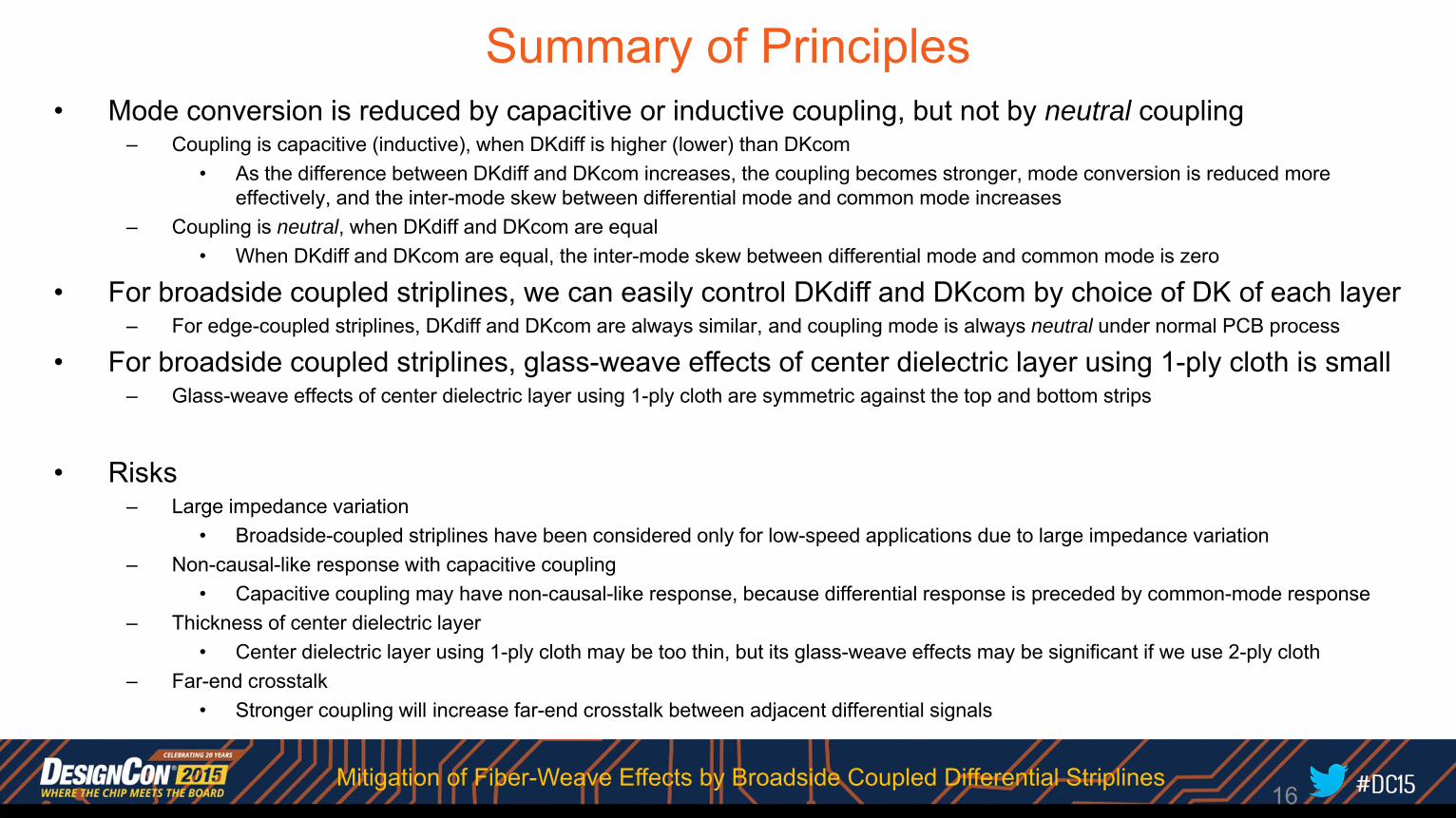
• Mode conversion is reduced by capacitive or inductive coupling, but not by neutral coupling– Coupling is capacitive (inductive), when DKdiff is higher (lower) than DKcom
• As the difference between DKdiff and DKcom increases, the coupling becomes stronger, mode conversion is reduced more effectively, and the inter-mode skew between differential mode and common mode increases
– Coupling is neutral, when DKdiff and DKcom are equal• When DKdiff and DKcom are equal, the inter-mode skew between differential mode and common mode is zero
• For broadside coupled striplines, we can easily control DKdiff and DKcom by choice of DK of each layer– For edge-coupled striplines, DKdiff and DKcom are always similar, and coupling mode is always neutral under normal PCB process
• For broadside coupled striplines, glass-weave effects of center dielectric layer using 1-ply cloth is small– Glass-weave effects of center dielectric layer using 1-ply cloth are symmetric against the top and bottom strips
• Risks– Large impedance variation
• Broadside-coupled striplines have been considered only for low-speed applications due to large impedance variation– Non-causal-like response with capacitive coupling
• Capacitive coupling may have non-causal-like response, because differential response is preceded by common-mode response– Thickness of center dielectric layer
• Center dielectric layer using 1-ply cloth may be too thin, but its glass-weave effects may be significant if we use 2-ply cloth– Far-end crosstalk
• Stronger coupling will increase far-end crosstalk between adjacent differential signals
Mitigation of Fiber-Weave Effects by Broadside Coupled Differential Striplines

Outline• Background• Principles• Implementation Issues• Evaluation Results• Summary
17Mitigation of Fiber-Weave Effects by Broadside Coupled Differential Striplines
PCP stack CPC stack
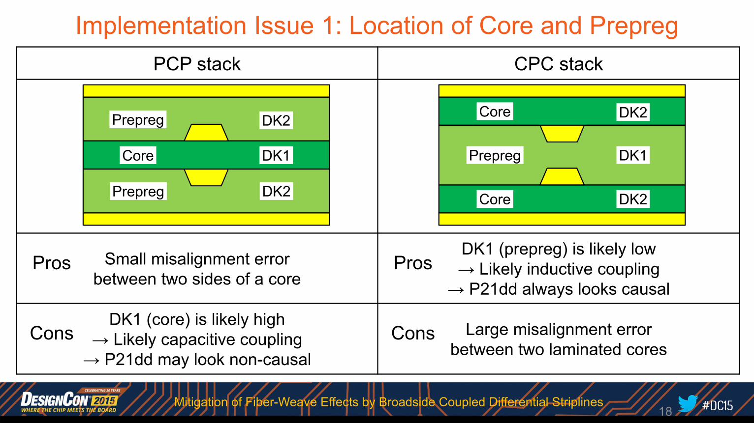
Small misalignment errorbetween two sides of a core
DK1 (prepreg) is likely low→ Likely inductive coupling
→ P21dd always looks causal
DK1 (core) is likely high→ Likely capacitive coupling→ P21dd may look non-causal
Large misalignment errorbetween two laminated cores
Implementation Issue 1: Location of Core and Prepreg
Core DK2
Prepreg DK1
Core DK2
Prepreg DK2
Core DK1
Prepreg DK2
Cons
Pros
Cons
Pros
18Mitigation of Fiber-Weave Effects by Broadside Coupled Differential Striplines
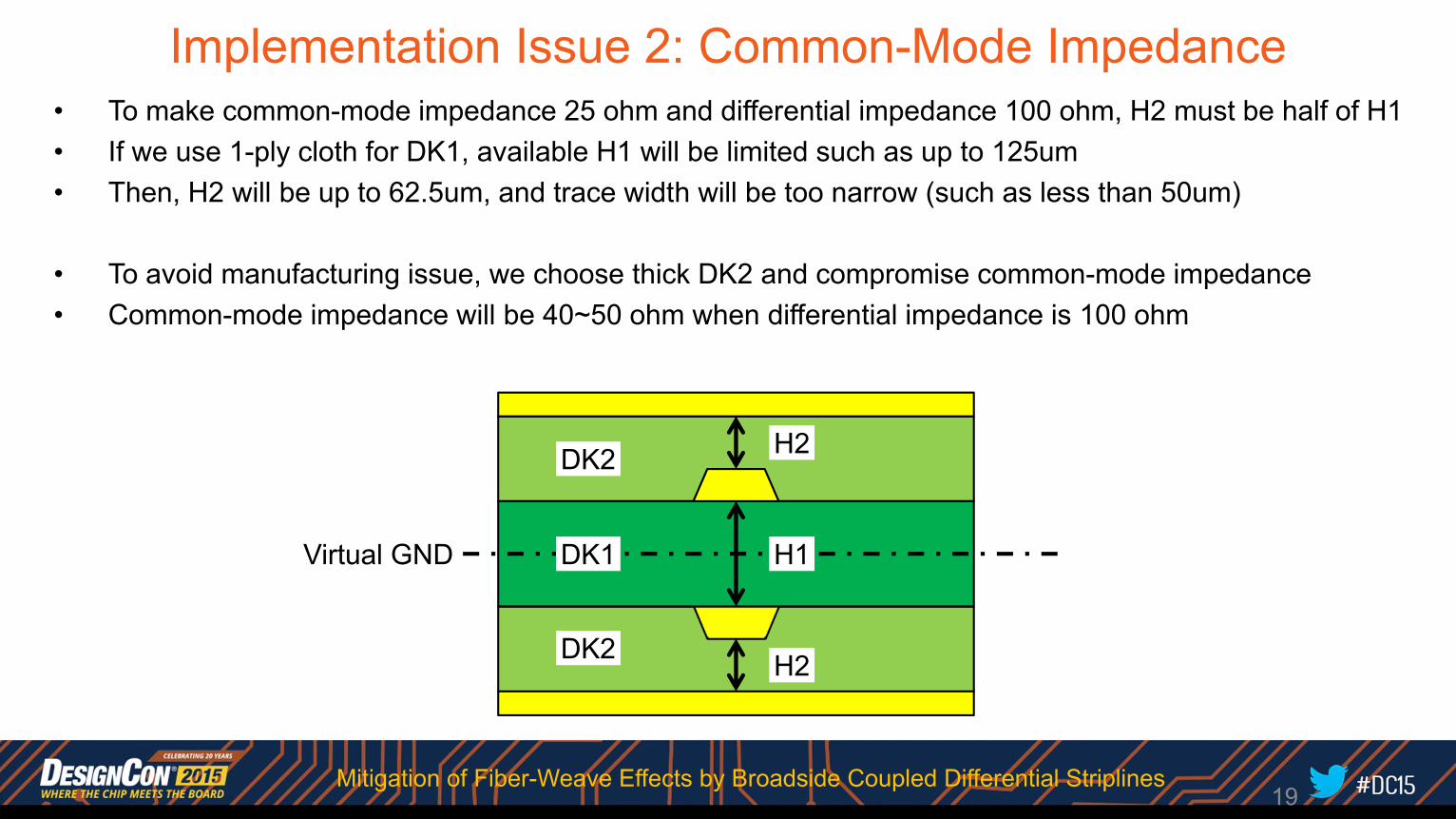
Implementation Issue 2: Common-Mode Impedance
19
• To make common-mode impedance 25 ohm and differential impedance 100 ohm, H2 must be half of H1• If we use 1-ply cloth for DK1, available H1 will be limited such as up to 125um• Then, H2 will be up to 62.5um, and trace width will be too narrow (such as less than 50um)
• To avoid manufacturing issue, we choose thick DK2 and compromise common-mode impedance• Common-mode impedance will be 40~50 ohm when differential impedance is 100 ohm
H2
H1
H2
DK2
DK1
DK2
Virtual GND
Mitigation of Fiber-Weave Effects by Broadside Coupled Differential Striplines
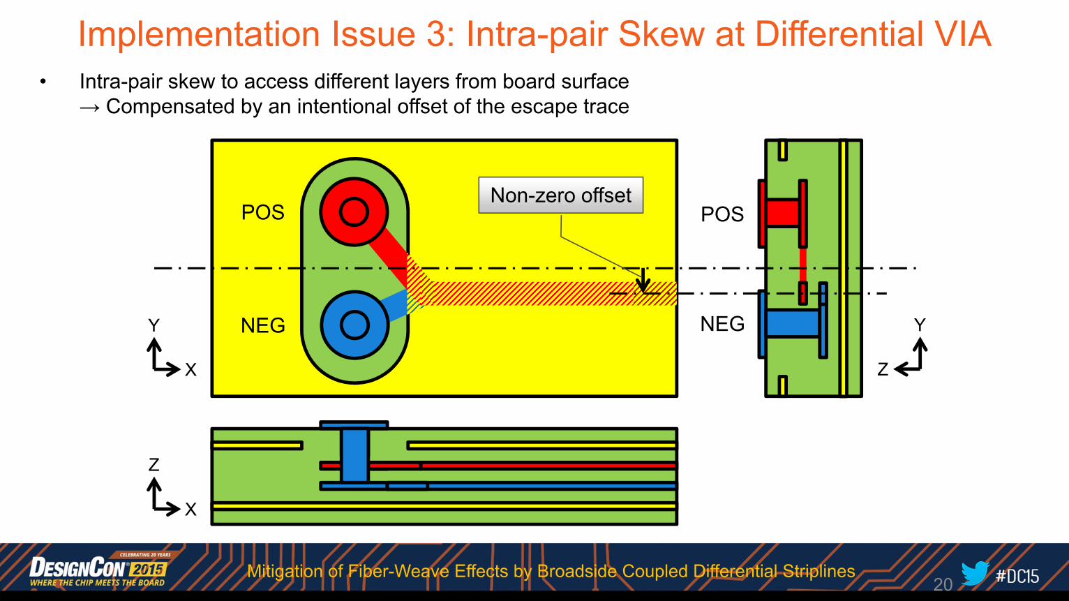
Implementation Issue 3: Intra-pair Skew at Differential VIA• Intra-pair skew to access different layers from board surface
→ Compensated by an intentional offset of the escape trace
POS
NEG
Z
Y
POS
NEG
X
Y
Non-zero offset
X
Z
20Mitigation of Fiber-Weave Effects by Broadside Coupled Differential Striplines
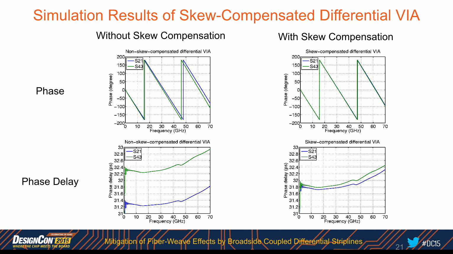
Simulation Results of Skew-Compensated Differential VIA
Phase
Phase Delay
Without Skew Compensation With Skew Compensation
21Mitigation of Fiber-Weave Effects by Broadside Coupled Differential Striplines
Outline• Background• Principles• Implementation Issues• Evaluation Results• Summary
22Mitigation of Fiber-Weave Effects by Broadside Coupled Differential Striplines
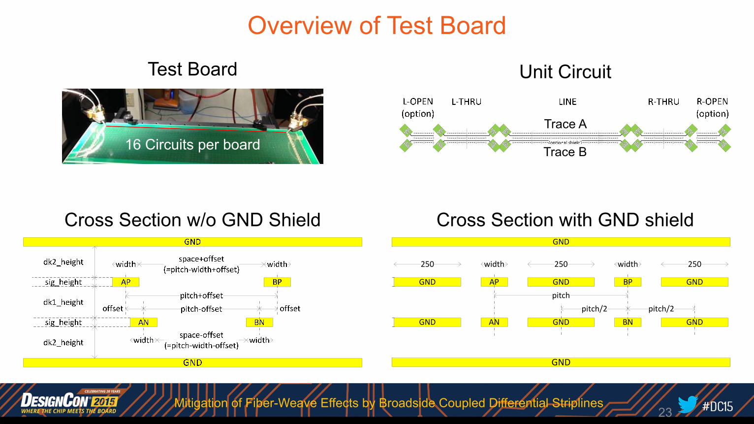
Overview of Test Board
Unit Circuit
Cross Section w/o GND ShieldGND
GND
AP
AN
BP
BN
GND
GND
GND
GND
GND
GND
width width250 250250
pitchpitch/2 pitch/2
Cross Section with GND shield
Test Board
Trace A
Trace B 16 Circuits per board
23Mitigation of Fiber-Weave Effects by Broadside Coupled Differential Striplines
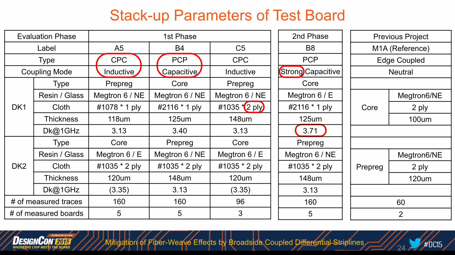
Stack-up Parameters of Test BoardEvaluation Phase 1st Phase
Label A5 B4 C5Type CPC PCP CPC
Coupling Mode Inductive Capacitive Inductive
DK1
Type Prepreg Core PrepregResin / Glass Megtron 6 / NE Megtron 6 / NE Megtron 6 / NE
Cloth #1078 * 1 ply #2116 * 1 ply #1035 * 2 plyThickness 118um 125um 148umDk@1GHz 3.13 3.40 3.13
DK2
Type Core Prepreg CoreResin / Glass Megtron 6 / E Megtron 6 / NE Megtron 6 / E
Cloth #1035 * 2 ply #1035 * 2 ply #1035 * 2 plyThickness 120um 148um 120umDk@1GHz (3.35) 3.13 (3.35)
# of measured traces 160 160 96# of measured boards 5 5 3
24
Previous ProjectM1A (Reference)
Edge CoupledNeutral
CoreMegtron6/NE
2 ply100um
PrepregMegtron6/NE
2 ply120um
602
2nd PhaseB8
PCPStrong Capacitive
CoreMegtron 6 / E#2116 * 1 ply
125um3.71
PrepregMegtron 6 / NE#1035 * 2 ply
148um3.131605
Mitigation of Fiber-Weave Effects by Broadside Coupled Differential Striplines
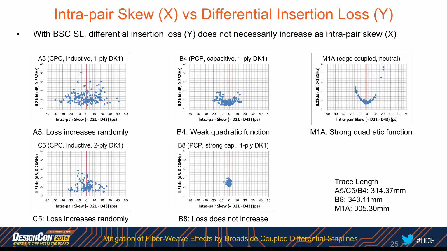
Intra-pair Skew (X) vs Differential Insertion Loss (Y)• With BSC SL, differential insertion loss (Y) does not necessarily increase as intra-pair skew (X)
A5: Loss increases randomly
C5: Loss increases randomly
B4: Weak quadratic function M1A: Strong quadratic function
B8: Loss does not increase
Trace LengthA5/C5/B4: 314.37mmB8: 343.11mmM1A: 305.30mm
25
15
20
25
30
35
40
‐50 ‐40 ‐30 ‐20 ‐10 0 10 20 30 40 50
IL21dd
(dB, 0‐28G
Hz)
Intra‐pair Skew (= D21 ‐ D43) (ps)
A5 (L300)A5 (CPC, inductive, 1-ply DK1)
15
20
25
30
35
40
‐50 ‐40 ‐30 ‐20 ‐10 0 10 20 30 40 50
IL21dd
(dB, 0‐28G
Hz)
Intra‐pair Skew (= D21 ‐ D43) (ps)
C5 (L300)C5 (CPC, inductive, 2-ply DK1)
15
20
25
30
35
40
‐50 ‐40 ‐30 ‐20 ‐10 0 10 20 30 40 50
IL21dd
(dB, 0‐28G
Hz)
Intra‐pair Skew (= D21 ‐ D43) (ps)
B4 (L300)B4 (PCP, capacitive, 1-ply DK1)
15
20
25
30
35
40
‐50 ‐40 ‐30 ‐20 ‐10 0 10 20 30 40 50
IL21dd
(dB, 0‐28G
Hz)
Intra‐pair Skew (= D21 ‐ D43) (ps)
B8 (L100x3)B8 (PCP, strong cap., 1-ply DK1)
15
20
25
30
35
40
‐50 ‐40 ‐30 ‐20 ‐10 0 10 20 30 40 50
IL21dd
(dB, 0‐28G
Hz)
Intra‐pair Skew (= D21 ‐ D43) (ps)
M1A (L100x3)M1A (edge coupled, neutral)
Mitigation of Fiber-Weave Effects by Broadside Coupled Differential Striplines
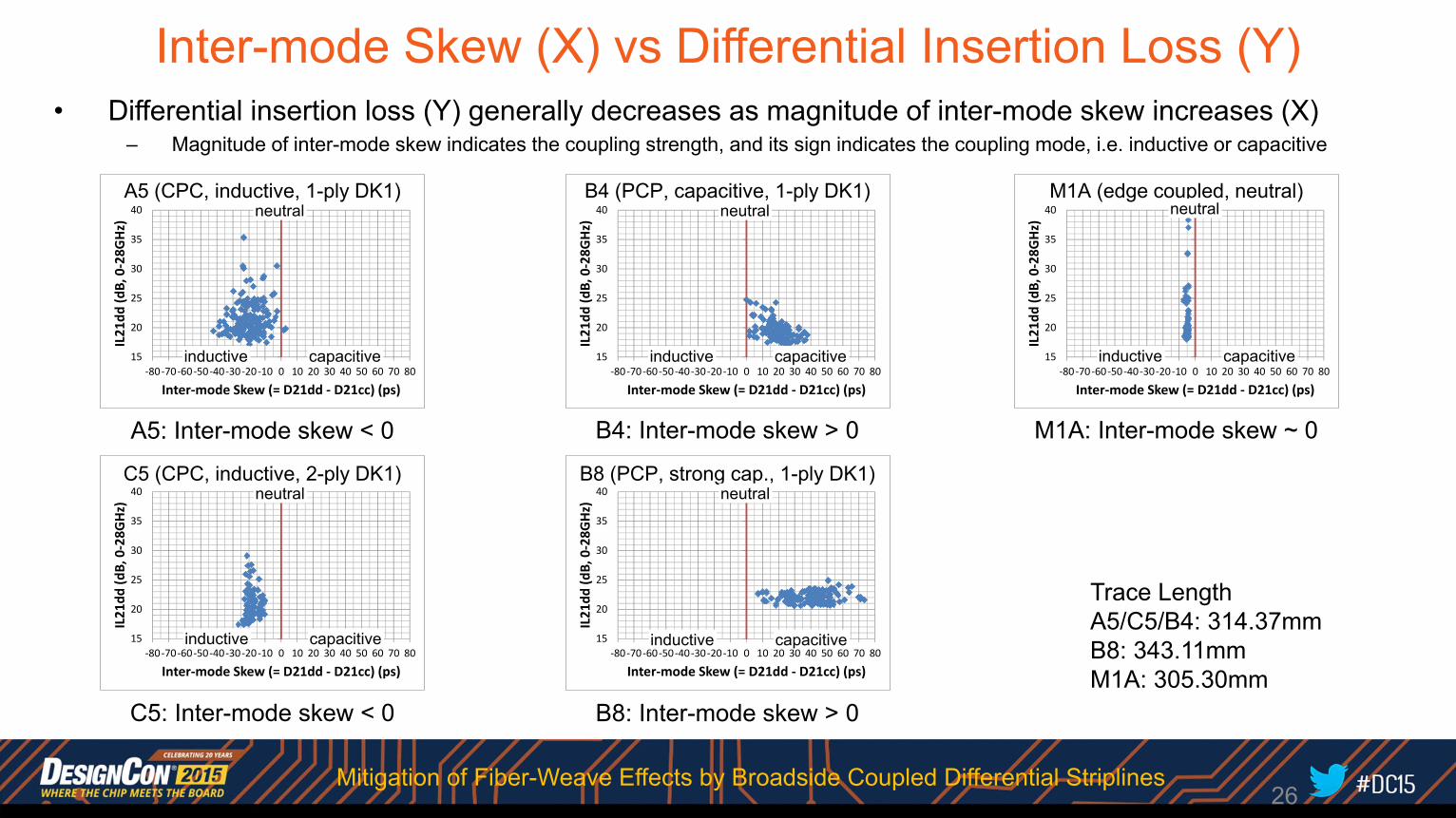
Inter-mode Skew (X) vs Differential Insertion Loss (Y)• Differential insertion loss (Y) generally decreases as magnitude of inter-mode skew increases (X)
– Magnitude of inter-mode skew indicates the coupling strength, and its sign indicates the coupling mode, i.e. inductive or capacitive
A5: Inter-mode skew < 0
C5: Inter-mode skew < 0
B4: Inter-mode skew > 0 M1A: Inter-mode skew ~ 0
B8: Inter-mode skew > 0
Trace LengthA5/C5/B4: 314.37mmB8: 343.11mmM1A: 305.30mm
26
15
20
25
30
35
40
‐80 ‐70 ‐60 ‐50 ‐40 ‐30 ‐20 ‐10 0 10 20 30 40 50 60 70 80
IL21dd
(dB, 0‐28G
Hz)
Inter‐mode Skew (= D21dd ‐ D21cc) (ps)
A5 (L300)
inductive capacitive
A5 (CPC, inductive, 1-ply DK1)neutral
15
20
25
30
35
40
‐80 ‐70 ‐60 ‐50 ‐40 ‐30 ‐20 ‐10 0 10 20 30 40 50 60 70 80
IL21dd
(dB, 0‐28G
Hz)
Inter‐mode Skew (= D21dd ‐ D21cc) (ps)
B4 (L300)
inductive capacitive
B4 (PCP, capacitive, 1-ply DK1)neutral
15
20
25
30
35
40
‐80 ‐70 ‐60 ‐50 ‐40 ‐30 ‐20 ‐10 0 10 20 30 40 50 60 70 80
IL21dd
(dB, 0‐28G
Hz)
Inter‐mode Skew (= D21dd ‐ D21cc) (ps)
M1A (L100x3)
inductive capacitive
M1A (edge coupled, neutral)neutral
15
20
25
30
35
40
‐80 ‐70 ‐60 ‐50 ‐40 ‐30 ‐20 ‐10 0 10 20 30 40 50 60 70 80
IL21dd
(dB, 0‐28G
Hz)
Inter‐mode Skew (= D21dd ‐ D21cc) (ps)
C5 (L300)
inductive capacitive
C5 (CPC, inductive, 2-ply DK1)neutral
15
20
25
30
35
40
‐80 ‐70 ‐60 ‐50 ‐40 ‐30 ‐20 ‐10 0 10 20 30 40 50 60 70 80
IL21dd
(dB, 0‐28G
Hz)
Inter‐mode Skew (= D21dd ‐ D21cc) (ps)
B8 (L100x3)
inductive capacitive
B8 (PCP, strong cap., 1-ply DK1)neutral
Mitigation of Fiber-Weave Effects by Broadside Coupled Differential Striplines
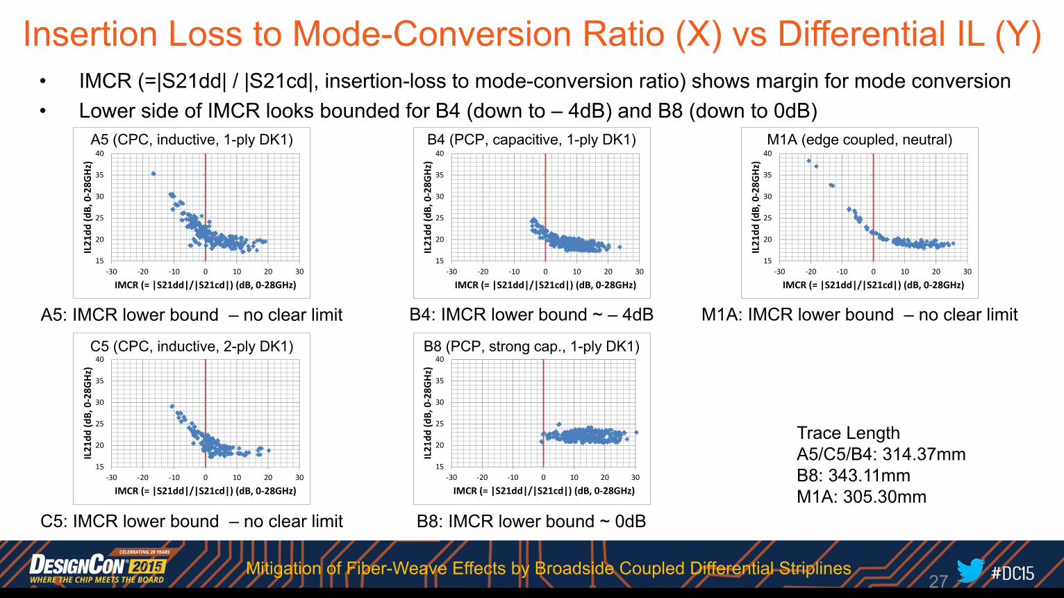
Insertion Loss to Mode-Conversion Ratio (X) vs Differential IL (Y)• IMCR (=|S21dd| / |S21cd|, insertion-loss to mode-conversion ratio) shows margin for mode conversion• Lower side of IMCR looks bounded for B4 (down to – 4dB) and B8 (down to 0dB)
A5: IMCR lower bound – no clear limit
C5: IMCR lower bound – no clear limit
B4: IMCR lower bound ~ – 4dB M1A: IMCR lower bound – no clear limit
B8: IMCR lower bound ~ 0dB
Trace LengthA5/C5/B4: 314.37mmB8: 343.11mmM1A: 305.30mm
27
15
20
25
30
35
40
‐30 ‐20 ‐10 0 10 20 30
IL21dd
(dB, 0‐28G
Hz)
IMCR (= |S21dd|/|S21cd|) (dB, 0‐28GHz)
A5 (L300)A5 (CPC, inductive, 1-ply DK1)
15
20
25
30
35
40
‐30 ‐20 ‐10 0 10 20 30
IL21dd
(dB, 0‐28G
Hz)
IMCR (= |S21dd|/|S21cd|) (dB, 0‐28GHz)
C5 (L300)C5 (CPC, inductive, 2-ply DK1)
15
20
25
30
35
40
‐30 ‐20 ‐10 0 10 20 30
IL21dd
(dB, 0‐28G
Hz)
IMCR (= |S21dd|/|S21cd|) (dB, 0‐28GHz)
B4 (L300)B4 (PCP, capacitive, 1-ply DK1)
15
20
25
30
35
40
‐30 ‐20 ‐10 0 10 20 30
IL21dd
(dB, 0‐28G
Hz)
IMCR (= |S21dd|/|S21cd|) (dB, 0‐28GHz)
B8 (L100x3)B8 (PCP, strong cap., 1-ply DK1)
15
20
25
30
35
40
‐30 ‐20 ‐10 0 10 20 30
IL21dd
(dB, 0‐28G
Hz)
IMCR (= |S21dd|/|S21cd|) (dB, 0‐28GHz)
M1A (L100x3)M1A (edge coupled, neutral)
Mitigation of Fiber-Weave Effects by Broadside Coupled Differential Striplines
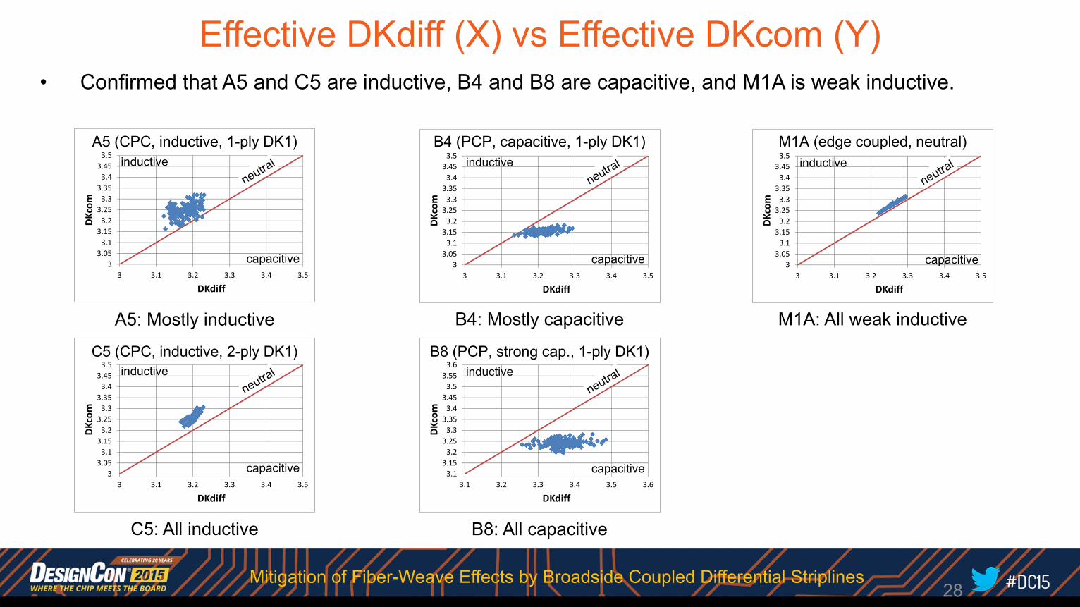
Effective DKdiff (X) vs Effective DKcom (Y)• Confirmed that A5 and C5 are inductive, B4 and B8 are capacitive, and M1A is weak inductive.
A5: Mostly inductive
C5: All inductive
B4: Mostly capacitive M1A: All weak inductive
B8: All capacitive
28
33.053.13.153.23.253.33.353.43.453.5
3 3.1 3.2 3.3 3.4 3.5
DKcom
DKdiff
A5 (L300)
inductive
capacitive
A5 (CPC, inductive, 1-ply DK1)
33.053.13.153.23.253.33.353.43.453.5
3 3.1 3.2 3.3 3.4 3.5
DKcom
DKdiff
C5 (L300)
inductive
capacitive
C5 (CPC, inductive, 2-ply DK1)
33.053.13.153.23.253.33.353.43.453.5
3 3.1 3.2 3.3 3.4 3.5
DKcom
DKdiff
B4 (L300)
inductive
capacitive
B4 (PCP, capacitive, 1-ply DK1)
3.13.153.23.253.33.353.43.453.53.553.6
3.1 3.2 3.3 3.4 3.5 3.6
DKcom
DKdiff
B8 (L100x3)
inductive
capacitive
B8 (PCP, strong cap., 1-ply DK1)
33.053.13.153.23.253.33.353.43.453.5
3 3.1 3.2 3.3 3.4 3.5
DKcom
DKdiff
M1A (L100x3)
inductive
capacitive
M1A (edge coupled, neutral)
Mitigation of Fiber-Weave Effects by Broadside Coupled Differential Striplines
15
20
25
30
35
40
‐80‐70 ‐60 ‐50‐40 ‐30 ‐20‐10 0 10 20 30 40 50 60 70 80
IL21
dd (d
B, 0‐28G
Hz)
Inter‐mode Skew (= D21dd ‐ D21cc) (ps)
A5 (L300)
inductive capacitive
neutral
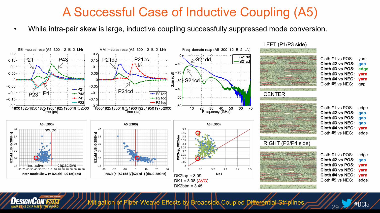
A Successful Case of Inductive Coupling (A5)• While intra-pair skew is large, inductive coupling successfully suppressed mode conversion.
33.053.13.153.23.253.33.353.43.453.5
3 3.1 3.2 3.3 3.4 3.5
DK2
top, DK2
btm
DK1
A5 (L300)
15
20
25
30
35
40
‐30 ‐20 ‐10 0 10 20 30
IL21
dd (d
B, 0‐28G
Hz)
IMCR (= |S21dd|/|S21cd|) (dB, 0‐28GHz)
A5 (L300)
DK2top = 3.09DK1 = 3.08 (AVG)DK2btm = 3.45
Cloth #1 vs POS: yarnCloth #2 vs POS: gapCloth #3 vs POS: edgeCloth #3 vs NEG: yarnCloth #4 vs NEG: yarnCloth #5 vs NEG: gap
LEFT (P1/P3 side)
Cloth #1 vs POS: edgeCloth #2 vs POS: gapCloth #3 vs POS: gapCloth #3 vs NEG: gapCloth #4 vs NEG: yarnCloth #5 vs NEG: edge
CENTER
Cloth #1 vs POS: edgeCloth #2 vs POS: gapCloth #3 vs POS: yarnCloth #3 vs NEG: yarnCloth #4 vs NEG: yarnCloth #5 vs NEG: edge
RIGHT (P2/P4 side)
29
P21 P43
P23
P21dd
P21cd
S21dd
S21cd
P21cc
P41
Mitigation of Fiber-Weave Effects by Broadside Coupled Differential Striplines
15
20
25
30
35
40
‐30 ‐20 ‐10 0 10 20 30
IL21
dd (d
B, 0‐28G
Hz)
IMCR (= |S21dd|/|S21cd|) (dB, 0‐28GHz)
B4 (L300)
33.053.13.153.23.253.33.353.43.453.5
3 3.1 3.2 3.3 3.4 3.5
DK2
top, DK2
btm
DK1
B4 (L300)
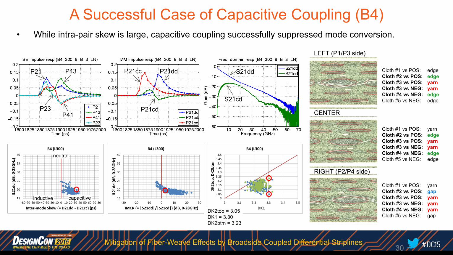
A Successful Case of Capacitive Coupling (B4)• While intra-pair skew is large, capacitive coupling successfully suppressed mode conversion.
Cloth #1 vs POS: edgeCloth #2 vs POS: edgeCloth #3 vs POS: yarnCloth #3 vs NEG: yarnCloth #4 vs NEG: edgeCloth #5 vs NEG: edge
LEFT (P1/P3 side)
Cloth #1 vs POS: yarnCloth #2 vs POS: edgeCloth #3 vs POS: yarnCloth #3 vs NEG: yarnCloth #4 vs NEG: edgeCloth #5 vs NEG: edge
CENTER
Cloth #1 vs POS: yarnCloth #2 vs POS: gapCloth #3 vs POS: yarnCloth #3 vs NEG: yarnCloth #4 vs NEG: yarnCloth #5 vs NEG: gap
RIGHT (P2/P4 side)
DK2top = 3.05DK1 = 3.30DK2btm = 3.23
30
P21 P43
P23
P21cc
P21cd
S21dd
S21cd
P21dd
P41
15
20
25
30
35
40
‐80‐70 ‐60 ‐50‐40 ‐30 ‐20‐10 0 10 20 30 40 50 60 70 80
IL21
dd (d
B, 0‐28G
Hz)
Inter‐mode Skew (= D21dd ‐ D21cc) (ps)
B4 (L300)
inductive capacitive
neutral
Mitigation of Fiber-Weave Effects by Broadside Coupled Differential Striplines
15
20
25
30
35
40
‐80‐70 ‐60 ‐50‐40 ‐30 ‐20‐10 0 10 20 30 40 50 60 70 80
IL21
dd (d
B, 0‐28G
Hz)
Inter‐mode Skew (= D21dd ‐ D21cc) (ps)
C5 (L300)
inductive capacitive
neutral
33.053.13.153.23.253.33.353.43.453.5
3 3.1 3.2 3.3 3.4 3.5
DK2
top, DK2
btm
DK1
C5 (L300)
15
20
25
30
35
40
‐30 ‐20 ‐10 0 10 20 30
IL21
dd (d
B, 0‐28G
Hz)
IMCR (= |S21dd|/|S21cd|) (dB, 0‐28GHz)
C5 (L300)
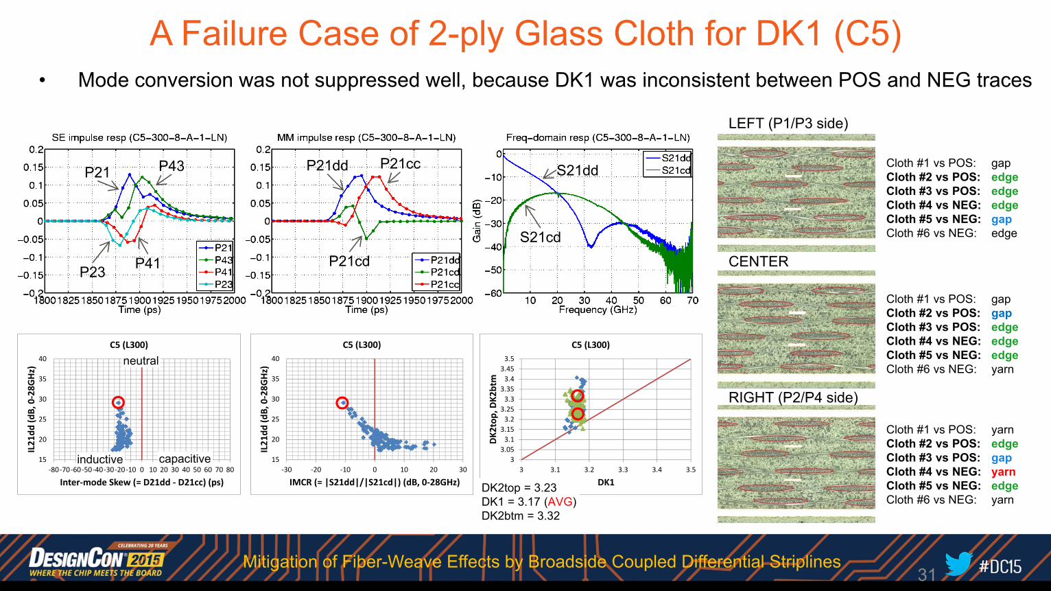
DK2top = 3.23DK1 = 3.17 (AVG)DK2btm = 3.32
A Failure Case of 2-ply Glass Cloth for DK1 (C5)• Mode conversion was not suppressed well, because DK1 was inconsistent between POS and NEG traces
Cloth #1 vs POS: gapCloth #2 vs POS: edgeCloth #3 vs POS: edgeCloth #4 vs NEG: edgeCloth #5 vs NEG: gapCloth #6 vs NEG: edge
LEFT (P1/P3 side)
Cloth #1 vs POS: gapCloth #2 vs POS: gapCloth #3 vs POS: edgeCloth #4 vs NEG: edgeCloth #5 vs NEG: edgeCloth #6 vs NEG: yarn
CENTER
Cloth #1 vs POS: yarnCloth #2 vs POS: edgeCloth #3 vs POS: gapCloth #4 vs NEG: yarnCloth #5 vs NEG: edgeCloth #6 vs NEG: yarn
RIGHT (P2/P4 side)
31
P21 P43
P23
P21dd
P21cd
S21dd
S21cd
P21cc
P41
Mitigation of Fiber-Weave Effects by Broadside Coupled Differential Striplines
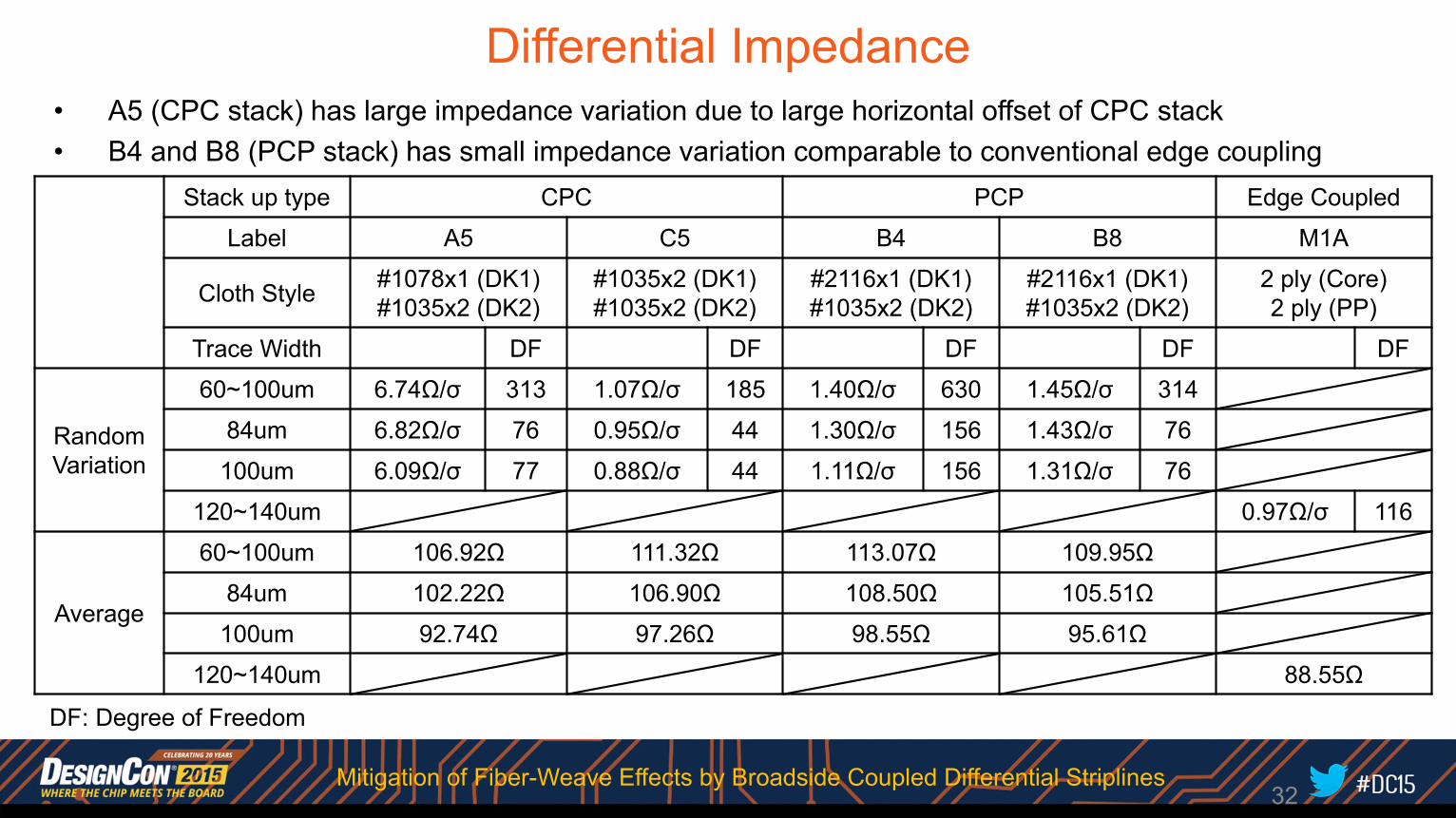
Differential Impedance• A5 (CPC stack) has large impedance variation due to large horizontal offset of CPC stack• B4 and B8 (PCP stack) has small impedance variation comparable to conventional edge coupling
Stack up type CPC PCP Edge Coupled
Label A5 C5 B4 B8 M1A
Cloth Style #1078x1 (DK1)#1035x2 (DK2)
#1035x2 (DK1)#1035x2 (DK2)
#2116x1 (DK1)#1035x2 (DK2)
#2116x1 (DK1)#1035x2 (DK2)
2 ply (Core)2 ply (PP)
Trace Width DF DF DF DF DF
Random Variation
60~100um 6.74Ω/σ 313 1.07Ω/σ 185 1.40Ω/σ 630 1.45Ω/σ 314
84um 6.82Ω/σ 76 0.95Ω/σ 44 1.30Ω/σ 156 1.43Ω/σ 76
100um 6.09Ω/σ 77 0.88Ω/σ 44 1.11Ω/σ 156 1.31Ω/σ 76
120~140um 0.97Ω/σ 116
Average
60~100um 106.92Ω 111.32Ω 113.07Ω 109.95Ω
84um 102.22Ω 106.90Ω 108.50Ω 105.51Ω
100um 92.74Ω 97.26Ω 98.55Ω 95.61Ω
120~140um 88.55Ω
32
DF: Degree of Freedom
Mitigation of Fiber-Weave Effects by Broadside Coupled Differential Striplines
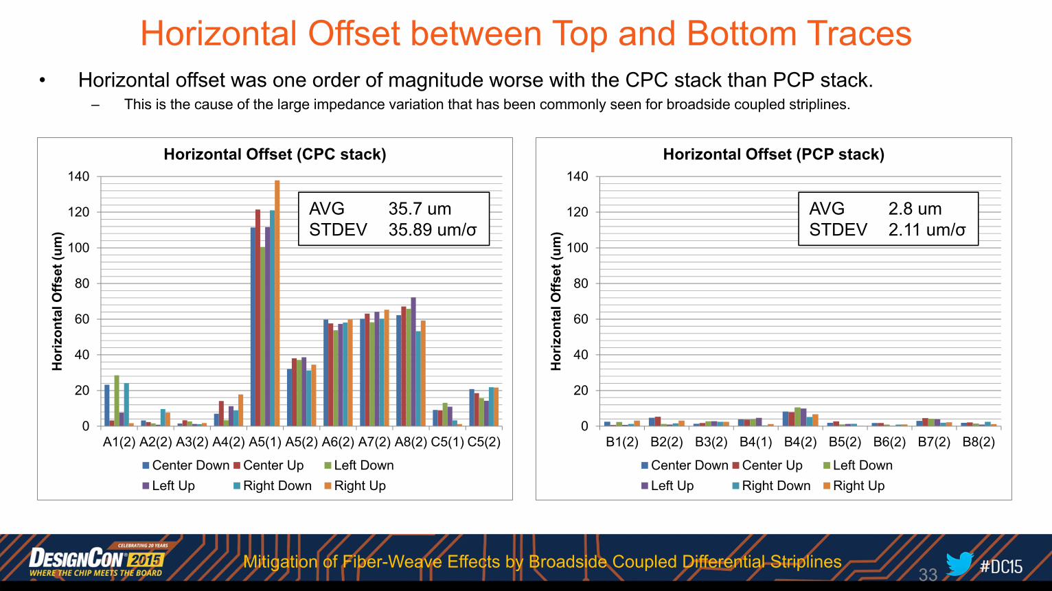
Horizontal Offset between Top and Bottom Traces• Horizontal offset was one order of magnitude worse with the CPC stack than PCP stack.
– This is the cause of the large impedance variation that has been commonly seen for broadside coupled striplines.
0
20
40
60
80
100
120
140
A1(2) A2(2) A3(2) A4(2) A5(1) A5(2) A6(2) A7(2) A8(2) C5(1) C5(2)
Hor
izon
tal O
ffset
(um
)
Horizontal Offset (CPC stack)
Center Down Center Up Left DownLeft Up Right Down Right Up
AVG 35.7 umSTDEV 35.89 um/σ
0
20
40
60
80
100
120
140
B1(2) B2(2) B3(2) B4(1) B4(2) B5(2) B6(2) B7(2) B8(2)
Hor
izon
tal O
ffset
(um
)
Horizontal Offset (PCP stack)
Center Down Center Up Left DownLeft Up Right Down Right Up
AVG 2.8 umSTDEV 2.11 um/σ
33Mitigation of Fiber-Weave Effects by Broadside Coupled Differential Striplines
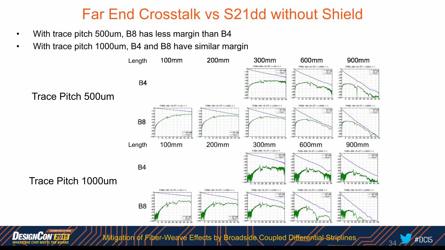
Far End Crosstalk vs S21dd without Shield• With trace pitch 500um, B8 has less margin than B4• With trace pitch 1000um, B4 and B8 have similar margin
Trace Pitch 500um
Trace Pitch 1000um
34Mitigation of Fiber-Weave Effects by Broadside Coupled Differential Striplines
Length
Length
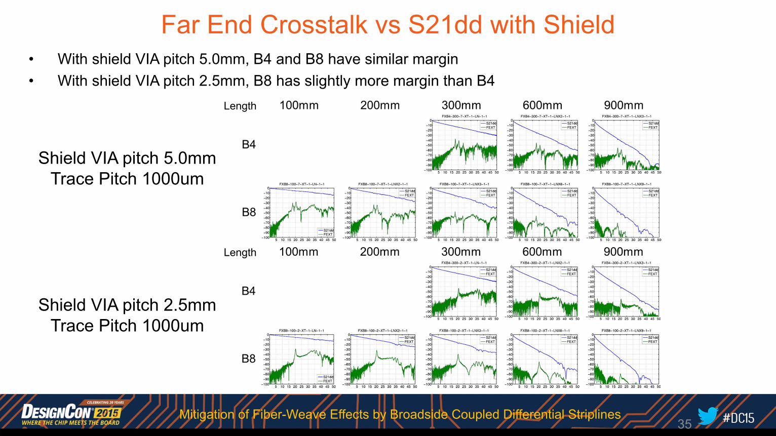
Far End Crosstalk vs S21dd with Shield• With shield VIA pitch 5.0mm, B4 and B8 have similar margin• With shield VIA pitch 2.5mm, B8 has slightly more margin than B4
Shield VIA pitch 5.0mmTrace Pitch 1000um
Shield VIA pitch 2.5mmTrace Pitch 1000um
35Mitigation of Fiber-Weave Effects by Broadside Coupled Differential Striplines
Length
Length
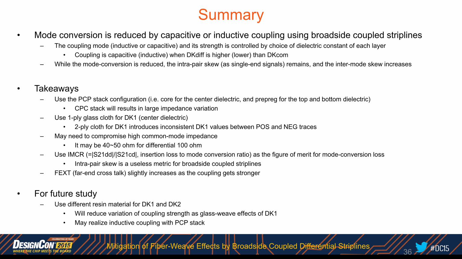
Summary• Mode conversion is reduced by capacitive or inductive coupling using broadside coupled striplines
– The coupling mode (inductive or capacitive) and its strength is controlled by choice of dielectric constant of each layer• Coupling is capacitive (inductive) when DKdiff is higher (lower) than DKcom
– While the mode-conversion is reduced, the intra-pair skew (as single-end signals) remains, and the inter-mode skew increases
• Takeaways– Use the PCP stack configuration (i.e. core for the center dielectric, and prepreg for the top and bottom dielectric)
• CPC stack will results in large impedance variation– Use 1-ply glass cloth for DK1 (center dielectric)
• 2-ply cloth for DK1 introduces inconsistent DK1 values between POS and NEG traces– May need to compromise high common-mode impedance
• It may be 40~50 ohm for differential 100 ohm– Use IMCR (=|S21dd|/|S21cd|, insertion loss to mode conversion ratio) as the figure of merit for mode-conversion loss
• Intra-pair skew is a useless metric for broadside coupled striplines– FEXT (far-end cross talk) slightly increases as the coupling gets stronger
• For future study– Use different resin material for DK1 and DK2
• Will reduce variation of coupling strength as glass-weave effects of DK1• May realize inductive coupling with PCP stack
36Mitigation of Fiber-Weave Effects by Broadside Coupled Differential Striplines
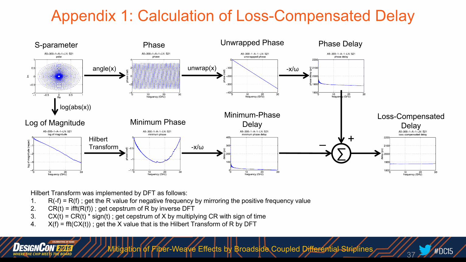
Appendix 1: Calculation of Loss-Compensated Delay
37
S-parameter Phase Unwrapped Phase
angle(x) unwrap(x)
Phase Delay
-x/ω
Log of Magnitude
log(abs(x))
Hilbert Transform was implemented by DFT as follows:1. R(-f) = R(f) ; get the R value for negative frequency by mirroring the positive frequency value2. CR(t) = ifft(R(f)) ; get cepstrum of R by inverse DFT3. CX(t) = CR(t) * sign(t) ; get cepstrum of X by multiplying CR with sign of time4. X(f) = fft(CX(t)) ; get the X value that is the Hilbert Transform of R by DFT
Minimum PhaseMinimum-Phase
Delay
-x/ω
Loss-CompensatedDelay
+–∑
HilbertTransform
Mitigation of Fiber-Weave Effects by Broadside Coupled Differential Striplines
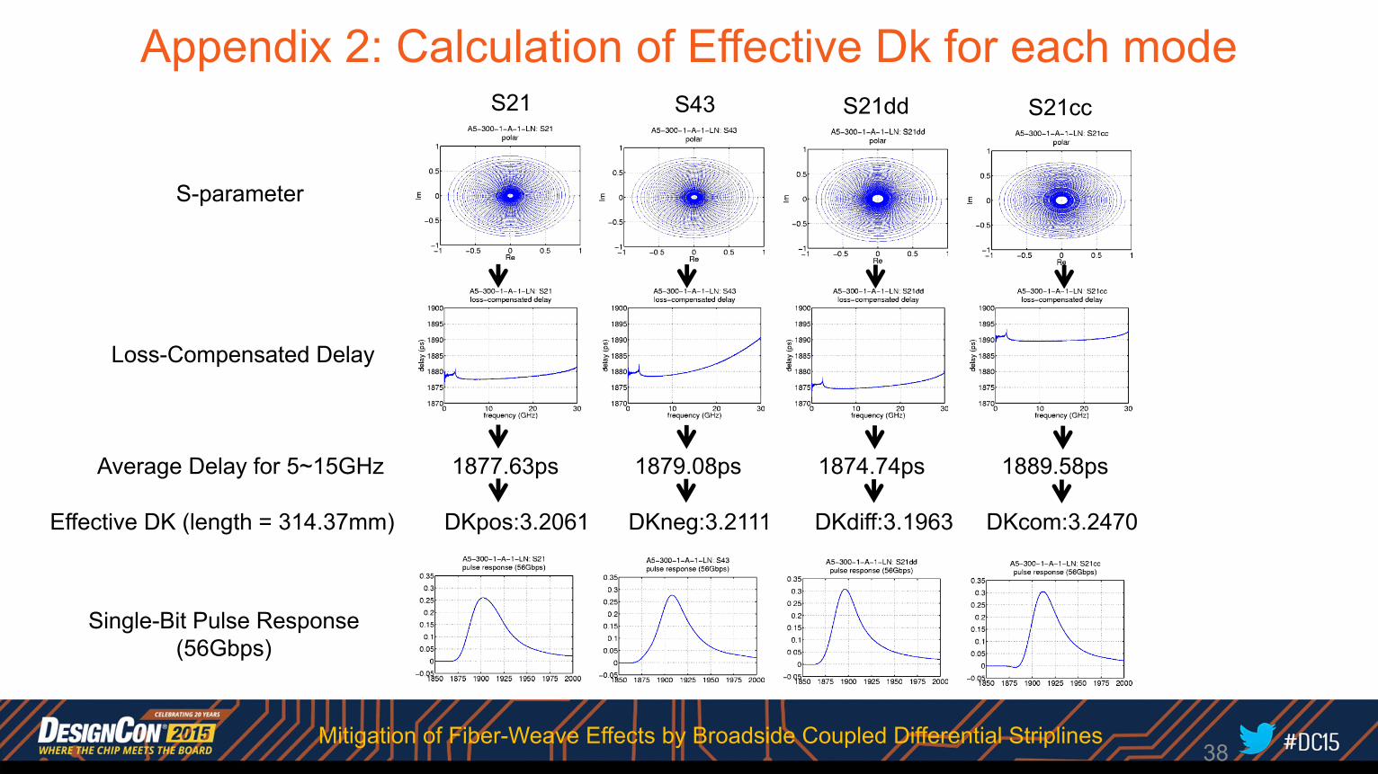
Appendix 2: Calculation of Effective Dk for each mode
38
S21 S43 S21dd S21cc
Single-Bit Pulse Response(56Gbps)
S-parameter
Loss-Compensated Delay
Effective DK (length = 314.37mm)
Average Delay for 5~15GHz 1877.63ps 1879.08ps 1874.74ps 1889.58ps
DKpos:3.2061 DKneg:3.2111 DKdiff:3.1963 DKcom:3.2470
Mitigation of Fiber-Weave Effects by Broadside Coupled Differential Striplines
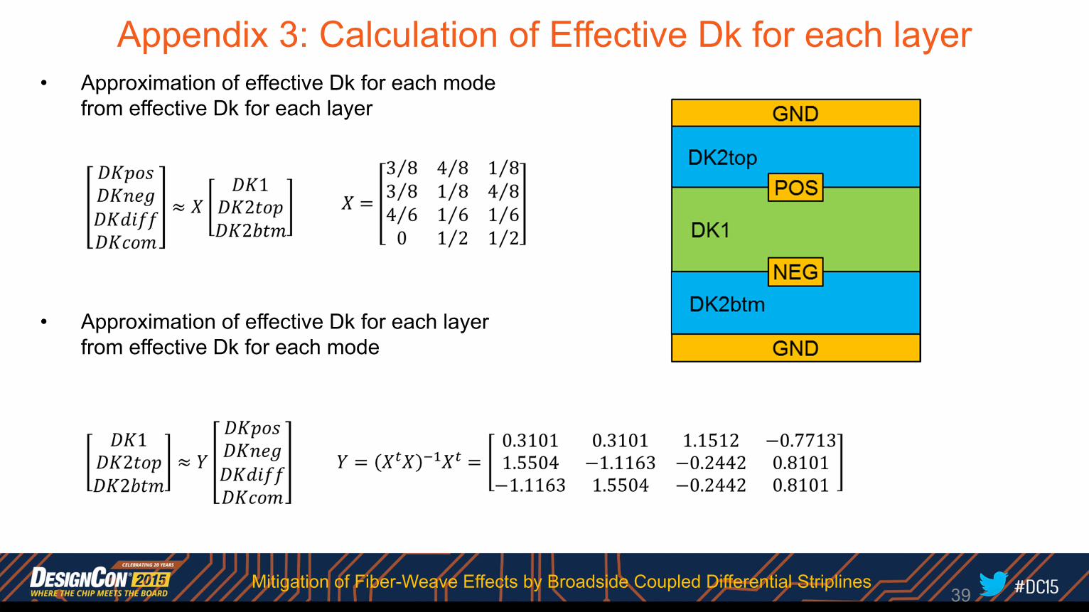
Appendix 3: Calculation of Effective Dk for each layer
39
• Approximation of effective Dk for each mode from effective Dk for each layer
• Approximation of effective Dk for each layer from effective Dk for each mode
Mitigation of Fiber-Weave Effects by Broadside Coupled Differential Striplines