Embed Size (px)
Citation preview
1
Mitigating the Right Turn Conflict Using Protected-Yet-Concurrent 1
Phasing for Cycle Track and Pedestrian Crossings 2
3
Peter G. Furth, Northeastern University 4
Peter J. Koonce, City of Portland 5
Miao Yu, Northeastern University 6
Fei Peng, Northeastern University 7
Michael Littman, Northeastern University 8
9
Submitted to the Transportation Research Board, August 1, 2013 10
Revised November 15, 2013 11
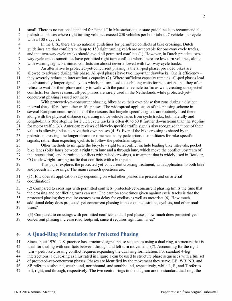
ABSTRACT 12 Pedestrian and bicycle crossings may need to be protected from right turns as well as left turns in 13 situations where there are high right turn volumes or speeds. The right turn volume threshold at which a 14 protected crossing is appropriate can be still smaller for cycle track crossings. This paper explores a 15 phasing scheme in which right turns as well as left turns have their own phase. The crossing runs at a 16 different time from the turn phases, yet concurrent with the parallel vehicular through phase. This 17 “protected-yet-concurrent” phasing scheme is far more efficient than using an all-ped phase. A general 18 framework for sequencing phases accounting for the right turn – crossing conflict is shown using four 19 rings instead of the usual two. Seven examples of protected-yet-concurrent phasing from the U.S. and the 20 Netherlands are used to illustrate the scheme and to characterize its likely impacts in terms of delay and 21 street footprint. Overall delay and footprint impacts are found to be modest; factors that affect the impact 22 of protected phasing include complexity of the phasing plan, coordination, and the possibility of using 23 phase re-service. Because protected-yet-concurrent phasing makes efficient use of time, it is also 24 economical with space. While it requires right turn lanes, its use can reduce the needed number of through 25 lanes, especially in comparison with all-ped phasing. 26
27
Where a bike path (cycle track) runs along the right side of a road, there is a conflict between through-28 going bikes and right-turning traffic, just as there is between pedestrians and right turns. The conflict can 29 either be permitted (turning vehicles advance on a green ball while the crossing phase is timing and are 30 expected to yield to through bikes and pedestrians) or protected. Protected phasing, meaning conflicting 31 turning movements are not allowed to run concurrently, can be provided either through an all-ped phase 32 (assuming bikes are allowed to use it), or by giving right turns, like left turns, their own signal phase, 33 governed by turn arrows and running at a different time than the crossing. In this latter scheme, the 34 crossing phase usually runs concurrently with a parallel through traffic phase, which presents no conflict 35 with the crossing. For this reason it may be called “protected-yet-concurrent” phasing. 36
Permitted conflicts with right turns are generally considered acceptable for pedestrian crossings 37 as long as the geometry forces right turns to be made at low speed and the right turn volume is acceptably 38
TRB 2014 Annual Meeting Paper revised from original submittal.
2
small. There is no national standard for “small.” In Massachusetts, a state guideline is to recommend all-1 pedestrian phases where right turning volumes exceed 250 vehicles per hour (about 7 vehicles per cycle 2 with a 100 s cycle). 3
In the U.S., there are no national guidelines for permitted conflicts at bike crossings. Dutch 4 guidelines are that conflicts with up to 150 right turning veh/h are acceptable for one-way cycle tracks, 5 and that two-way cycle tracks should avoid all permitted conflicts (1). However, in Dutch practice, two-6 way cycle tracks sometimes have permitted right turn conflicts where there are low turn volumes, along 7 with warning signs. Permitted conflicts are almost never allowed with two-way cycle tracks. 8
An alternative to protected-yet-concurrent phasing is the all-ped phase, provided bikes are 9 allowed to advance during this phase. All-ped phases have two important drawbacks. One is efficiency – 10 they severely reduce an intersection’s capacity (2). Where sufficient capacity remains, all-ped phases lead 11 to substantially longer signal cycles which, in turn, lead to such long waits for pedestrians that they often 12 refuse to wait for their phase and try to walk with the parallel vehicle traffic as well, creating unexpected 13 conflicts. For these reasons, all-ped phases are rarely used in the Netherlands while protected-yet-14 concurrent phasing is used routinely. 15
With protected-yet-concurrent phasing, bikes have their own phase that runs during a distinct 16 interval that differs from other traffic phases. The widespread application of this phasing scheme in 17 several European countries is one of the reasons that bicycle-specific signals are routinely used there, 18 along with the physical distance separating motor vehicle lanes from cycle tracks, both laterally and 19 longitudinally (the stopline for Dutch cycle tracks is often 40 to 60 ft further downstream than the stopline 20 for motor traffic (3)). American reviews of bicycle-specific traffic signals also recognize that one of their 21 values is allowing bikes to have their own phases (4, 5). Even if the bike crossing is shared by the 22 pedestrian crossing, the longer clearance time needed by pedestrians also militates for bike-specific 23 signals, rather than expecting cyclists to follow the pedestrian signal. 24
Other methods to mitigate the bicycle – right turn conflict include leading bike intervals, pocket 25 bike lanes (bike lanes between a right turn lane and a through lane, which move the conflict upstream of 26 the intersection), and permitted conflicts with raised crossings, a treatment that is widely used in Boulder, 27 CO to slow right-turning traffic that conflicts with a bike path. 28
This paper explores the protected-yet-concurrent crossing treatment, with application to both bike 29 and pedestrian crossings. The main research questions are: 30
(1) How does its application vary depending on what other phases are present and on arterial 31 coordination? 32
(2) Compared to crossings with permitted conflicts, protected-yet-concurrent phasing limits the time that 33 the crossing and conflicting turns can run. One caution sometimes given against cycle tracks is that the 34 protected phasing they require creates extra delay for cyclists as well as motorists (6). How much 35 additional delay does protected-yet-concurrent phasing impose on pedestrians, cyclists, and other road 36 users? 37
(3) Compared to crossings with permitted conflicts and all-ped phases, how much does protected-yet-38 concurrent phasing increase road footprint, since it requires right turn lanes? 39
A Quad-Ring Formulation for Protected Phasing 40
Since about 1970, U.S. practice has structured signal phase sequences using a dual ring, a structure that is 41 ideal for dealing with conflicts between through and left turn movements (7). Accounting for the right 42 turn – ped/bike crossing conflict requires expanding the dual ring formulation. For standard 4-leg 43 intersections, a quad-ring as illustrated in Figure 1 can be used to structure phase sequences with a full set 44 of protected-yet-concurrent phases. Phases are identified by the movement they serve. EB, WB, NB, and 45 SB refer to eastbound, westbound, northbound, and southbound, respectively, while L, R, and T refer to 46 left, right, and through, respectively. The two central rings in the diagram are the standard dual ring; the 47
TRB 2014 Annual Meeting Paper revised from original submittal.

3
outer rings contain the right turn and crossing phases. The figure has been drawn with lagging lefts and 1 leading rights; leading lefts and lagging rights are also possible. This control structure is common at 2 intersections in the Netherlands, where most main roads have cycle tracks. In the U.S., most modern 3 controller software allows for four or more rings. 4
As the figure shows, right turn phases can overlap two central phases: a parallel left turn phase 5 from the cross street and a through phase from the same approach. Crossings are concurrent with a 6 parallel through phase, but may begin later or end earlier than the through phase to allow more time for 7 the conflicting right turn phase. 8
Signal cycle length is governed by a critical ring or critical conflict group, a set of mutually 9 conflicting movements that must be served serially and require more time to be served than any other 10 such group of movements. Traffic volumes are usually such that the right turns are rarely critical. That 11 means that the rings with the right turn and crossing phases usually have some slack that can be used to 12 improve safety and efficiency. 13
14
15 Figure 1. Quad ring structure for a full set of protected-yet-concurrent crossings at a 4-leg junction, 16
drawn with lagging lefts and leading rights. Dashed lines indicate a phase that (partially) belongs to a 17 previous or later cycle. Heavy lines indicate the standard dual ring. Vertical bars represent bike-ped 18
crossings. 19
20
Examples 21
This research examines several examples of protected-yet-concurrent phasing drawn from the U.S. and 22 the Netherlands. For many of them, the phasing sequence can be structured with fewer than four rings. 23 The last example shows a potential quad-ring application in the U.S. 24
Broadway Bridge @ Lovejoy: Simple Right Turn Overlap 25
Cyclists going southwest (labeled south) over the Broadway Bridge in Portland, OR are directed from a 26 shared use path into a one-way cycle track as they approach Lovejoy Street, where they have a conflict 27 with a heavily used right turning movement whose geometry allows higher speed turns. The phasing plan 28 in Figure 2 characterizes signal operations before the recent expansion of the Portland Streetcar to this 29 intersection. It is a classic case in which the conflicting right turn movement, SBR, can run concurrently 30 with the cross street left turn (EBL), so that the time of the mainline through (SBT) phase can then be 31
SBL
EBT WBL
||||EBRNBR
NBT||||
SBL
WBR
WBT EBL SBT NBL
||||
WBR SBR
|||| EBR
NBL
||||
||||
One Cycle
TRB 2014 Annual Meeting Paper revised from original submittal.

4
split between serving excess demand for SBR and serving bikes and pedestrians on the west side crossing. 1 This sort of configuration is commonly implemented using overlaps in the signal controller and 2 essentially provides a third ring to the standard NEMA ring-barrier structure. The phases are actuated, so 3 that SBR consumes no more of the mainline through phase than is needed each cycle. That way slack 4 time goes to the bike crossing, helping lower cyclist delay. 5
6 Figure 2. Phase Sequences for Broadway Bridge @ Lovejoy. Protected bike-ped crossing and right turn 7 movement are shown as intervals with heavy outline. 8
9
Because the traffic volume and geometry of the conflict requires a protected crossing of Lovejoy 10 for pedestrians, providing a protected crossing for cyclists imposes no additional delay on motorists. For 11 through cyclists, a protected crossing gives cyclists less green time than they would have if the bicycle 12 treatment were to transition the cycle track to a pocket bike lane, which would allow cyclists to be served 13 during the entire SBT phase. If �d is defined as the difference in average delay for bikes between 14 operation with versus without protected phasing, then 15
( ) ( )
⎟⎟⎟
⎠
⎞
⎜⎜⎜
⎝
⎛
−⎥⎥⎦
⎤
⎢⎢⎣
⎡ −−
−=Δ
svC
gCCgC
d thrubike
11
22
22
16
17
where C = cycle length, gbike and gthru are the effective green times for a protected bike phase and for the 18 parallel through traffic phase respectively, and v/s is the flow ratio for bicycles. Example calculations 19 assume that v/s = 0.08, C = 80 s, gT = 44 s, and that gb ranges from 37 s (as might happen if the right turn 20 movement is not much heavier than the EBL movement) to 24 s (as might happen when the right turn 21 movement is heavy). With a pocket bike lane and therefore without protected phasing, average delay is 9 22 s; with a cycle track and protected phasing, average delay is in the range 13 to 25 s, depending on how 23 much time SBR traffic needs. The additional delay is a small and reasonable price for cyclists to pay for 24 the benefit of protection from conflict with turning traffic. An interesting result of Equation 1 is that when 25 right turn volume is low, which is when a pocket bike lane would be most acceptable to cyclists, the 26 additional delay from protected phasing is also very small. 27
3rd Street: Left Side Conflicts on One-Way Streets 28
Long Beach, California’s 3rd Street and New York City’s 9th Avenue are examples of one-way streets 29 with one-way cycle tracks positioned along the left side, which eliminates bike conflicts at bus stops. The 30 left side position creates intersection conflicts with left turning traffic that correspond to the conventional 31 right turn conflict, but with no opportunity for the conflicting turns to run during an overlap with a cross 32 street phase. Therefore, protected phasing requires that the bike-ped crossing and the conflicting lefts 33 allocate between them the “half-cycle” controlled by the mainline through movement. 34
NBT
EBL(R) SBT
SBR
||||
||||
Lovejoy
TRB 2014 Annual Meeting Paper revised from original submittal.

5
A generalized phasing plan is shown in Figure 3, with mainline being westbound. The lower ring 1 shows the westbound half-cycle divided between one interval for the bike-ped crossing and two intervals 2 for left turns, similar to a conditional service operation (8). Actual operation on 3rd Street uses leading 3 lefts and skips the lagging left interval unless the leading left was skipped for lack of a call. When left 4 turn demand is enough that leading lefts occur routinely, the additional delay to bikes compared to 5 unprotected phasing is about 7 s, assuming random bike arrivals and a 70 s cycle with a 40 s split for the 6 mainline. 7
8
9 Figure 3. Phase Sequence with Left Turn Reservice and a Protected Crossing for Left-Side Cycle Track 10
11
Where the conflicting turning movement is actuated, the most advantageous sequence for bikes is 12 when the conflicting turn leads and the bike crossing lags. That way, the conflicting turns consume only 13 the time they need, and the remainder of the mainline half-cycle goes to the bikes, maximizing their 14 green. This can be especially valuable where the mainline half-cycle does not have a fixed ending time. 15 With fixed time control, sequence does not affect delay, but there may be a safety advantage to leading 16 with the bike-ped crossing, since pedestrians and cyclists are eager to cross as soon as the cross street 17 phase ends and may not wait for a lagging phase. 18
For Long Beach’s 3rd Street, compared to the previous regime in which westbound lefts had a 19 permissive green during the entire mainline half-cycle, having a short protected phase and no turn on red 20 increases this movement’s delay considerably. The lagging left option helps reduce left turn delay during 21 light traffic periods of the day, and imposes no additional delay on bikes since it is only applied when the 22 leading left is skipped. Where the mainline half-cycle is long enough, the turning movement delay could 23 be reduced substantially by setting the controller to routinely provide both leading and lagging turn 24 phases, following the model of Figure 3. This reservice tactic roughly halves the length of the red periods 25 facing the turning movement, and therefore roughly halves its delay, though it involves some additional 26 bike delay. Where the intersecting street is also one-way, a third way to reduce turning movement delay is 27 to have a part-time restriction on left or right turn on red, using blank-out signs indicating No Turn on 28 Red during the protected crossing while allowing turns during other parts of the cycle. Portland, OR has 29 used this technique effectively to minimize the added delay imposed on turning traffic from protecting 30 bicycling movements. 31
9th Avenue: Delay Related to Arterial Coordination 32
New York’s 9th Avenue is a one-way street with a left side cycle track with protected phasing, with a 33 leading bike-ped phase followed by a fixed duration lagging left. Due to the close intersection spacing 34 and one-way progression, bicycles do not arrive at random, but rather arrive as they are released from 35 upstream intersections. If the signals progress at a speed greater than cyclist speed, through-going cyclists 36 starting on a fresh green will be able to travel without delay through several intersections, arriving later 37 and later within the green band, until they arrive so late that they have to stop for a full red period. Using 38 a continuous approximation and assuming a common cycle length C and effective bicycle green period g 39 at all intersections, the distance xnonstop that a cyclist can travel between stops is given by 40
WBL WBL||||
||||WBT N‐S
||||
||||
TRB 2014 Annual Meeting Paper revised from original submittal.

6
⎟⎟⎠
⎞⎜⎜⎝
⎛−
=
pb
nonstop
uu
gx11
(2) 1
where ub = bicycle speed and up = progression speed for the traffic signals (assuming up > ub). Cyclist 2 delay per unit distance, �, is one red period’s duration per distance xnonstop, or 3
⎟⎟⎠
⎞⎜⎜⎝
⎛−
−=
pb uuggC 11δ � 4
Equation 3 shows that with arterial coordination, bike delay is doubly sensitive to effective green time – 5 less green time means both more delay per stop (reflected in the numerator), and more frequent stops 6 (reflected in the denominator). 7
Some example results are given in Table 1, assuming C = 80 s, ub = 12 mph, a mainline through 8 effective green of 46 s, and a 12 s split for a protected left turn phase if provided. With a progression 9 speed of 40 ft/s (about 27 mph), introducing a protected left turn phase increases delay to through bikes 10 by a substantial 1.7 min/mi, because it shortens xnonstop from 1450 to 1070 ft. However, cyclists’ need for a 11 long green period is not as important if the progression speed is closer to bike speed. As the table shows, 12 if progression speed is lowered to 22 ft/s (about 15 mph), bikes’ effective speed increases substantially, 13 and the same shortening of the bike green increases their delay by only 0.6 min/mi. Lower progression 14 speeds also improve safety, progression for buses, and throughput (by compressing platoons when 15 vehicles turn off the arterial). For these reasons, Portland times its downtown traffic signals with a 16 progression speed of 13 to 16 mph depending on time of day. San Francisco also uses low progression 17 speeds on some of its corridors as part of its “Green Wave” program (7). 18
Taylor and Mahmassani (9) point out that “perfect” bicycle and motor vehicle progression can 19 also be provided in a scheme in which bicycles take one full cycle longer (or any integer number of 20 cycles) to reach the next intersection than motor vehicles. For example, if motor vehicle speed is 44 ft/s 21 and bikes 17 ft/s, and intersection spacing is 1660 ft, then motor vehicles need 37 s and bikes 97 s to 22 reach the next intersection. If the cycle length is 60 s, then an offset giving ideal progression for motor 23 vehicles will also provide ideal progression for bikes. The closer to ideal bike progression is, the less 24 sensitive bike delay is to having its green time shortened for protected phasing. However, such a scheme 25 is dependent on intersection spacing being matched to cycle length, limiting possibilities for application. 26
For short sections of road with arterial progression, the distance over which bikes can progress 27 nonstop can be increased by giving bikes a leading phase at the early set of intersections and a lagging 28 phase at the latter intersections. With this device, xnonstop with protected phasing will be the same as it 29 would be if bikes used the full mainline green interval. 30
Broadway & N. Williams: Coordination Results in Little Bike Delay in Spite of a 31 Short Bike Phase 32
At the junction of Broadway and N. Williams Avenue in Portland, westbound bikes along Broadway face 33 a conflict from a very heavy right turn flow from Broadway onto N. Williams en route to the I-5 freeway 34 entrance. Until 2011, bikes had a pocket bike lane with a right turn lane on their right and a through-right 35 lane on their left – not a desirable layout. In 2011, the through-right lane was converted to right turn only, 36 giving Broadway dual right turn lanes, and the bike lane was shifted to the right curb. At the same time, 37 protected phasing was introduced to separate bikes from the dual right turns. (This example illustrates 38 how protected bike phasing can be applied with bike lanes as well as with cycle tracks.) Because the 39 heavy right turning demand requires a fair amount of green time, the protected bike phase would have to 40 be short. With bikes arriving at random, that would result in rather long delays for bikes. Instead, a 41 coordination scheme was developed in which a bike phase was also introduced at the upstream 42
TRB 2014 Annual Meeting Paper revised from original submittal.
7
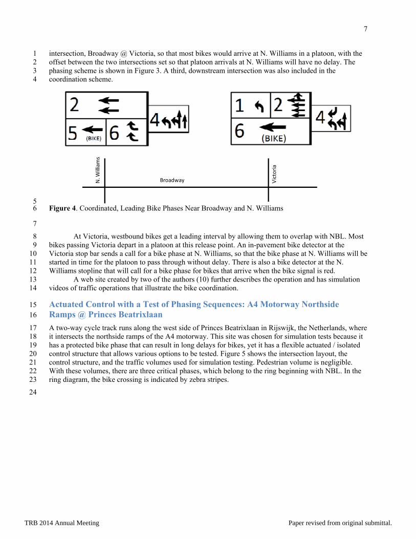
intersection, Broadway @ Victoria, so that most bikes would arrive at N. Williams in a platoon, with the 1 offset between the two intersections set so that platoon arrivals at N. Williams will have no delay. The 2 phasing scheme is shown in Figure 3. A third, downstream intersection was also included in the 3 coordination scheme. 4
5 Figure 4. Coordinated, Leading Bike Phases Near Broadway and N. Williams 6
7
At Victoria, westbound bikes get a leading interval by allowing them to overlap with NBL. Most 8 bikes passing Victoria depart in a platoon at this release point. An in-pavement bike detector at the 9 Victoria stop bar sends a call for a bike phase at N. Williams, so that the bike phase at N. Williams will be 10 started in time for the platoon to pass through without delay. There is also a bike detector at the N. 11 Williams stopline that will call for a bike phase for bikes that arrive when the bike signal is red. 12
A web site created by two of the authors (10) further describes the operation and has simulation 13 videos of traffic operations that illustrate the bike coordination. 14
Actuated Control with a Test of Phasing Sequences: A4 Motorway Northside 15 Ramps @ Princes Beatrixlaan 16
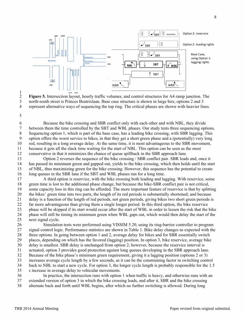
A two-way cycle track runs along the west side of Princes Beatrixlaan in Rijswijk, the Netherlands, where 17 it intersects the northside ramps of the A4 motorway. This site was chosen for simulation tests because it 18 has a protected bike phase that can result in long delays for bikes, yet it has a flexible actuated / isolated 19 control structure that allows various options to be tested. Figure 5 shows the intersection layout, the 20 control structure, and the traffic volumes used for simulation testing. Pedestrian volume is negligible. 21 With these volumes, there are three critical phases, which belong to the ring beginning with NBL. In the 22 ring diagram, the bike crossing is indicated by zebra stripes. 23
24
Broadway Victoria
N. W
illiams
TRB 2014 Annual Meeting Paper revised from original submittal.
8
1 Figure 5. Intersection layout, hourly traffic volumes, and control structures for A4 ramp junction. The 2 north-south street is Princes Beatrixlaan. Base case structure is shown in large box; options 2 and 3 3 represent alternative ways of sequencing the top ring. The critical phases are shown with heavier lines. 4
5
Because the bike crossing and SBR conflict only with each other and with NBL, they divide 6 between them the time controlled by the SBT and WBL phases. Our study tests three sequencing options. 7 Sequencing option 1, which is part of the base case, has a leading bike crossing, with SBR lagging. This 8 option offers the worst service to bikes, in that they get a short green phase and a (potentially) very long 9 red, resulting in a long average delay. At the same time, it is most advantageous to the SBR movement, 10 because it gets all the slack time waiting for the start of NBL. This option can be seen as the most 11 conservative in that it minimizes the chance of queue spillback in the SBR approach lane. 12
Option 2 reverses the sequence of the bike crossing / SBR conflict pair. SBR leads and, once it 13 has passed its minimum green and gapped out, yields to the bike crossing, which then holds until the start 14 of NBL, thus maximizing green for the bike crossing. However, this sequence has the potential to create 15 long queues in the SBR lane if the SBT and WBL phases run for a long time. 16
A third option is reservice, with the bike crossing both leading and lagging. With reservice, some 17 green time is lost to the additional phase change, but because the bike-SBR conflict pair is not critical, 18 some capacity loss in this ring can be afforded. The more important feature of reservice is that by splitting 19 the bikes’ green time into two parts, the length of its red periods is substantially shortened; and because 20 delay is a function of the length of red periods, not green periods, giving bikes two short green periods is 21 far more advantageous than giving them a single longer period. In this third option, the bike reservice 22 phase will be skipped if its start would occur after the start of WBL in order to lessen the risk that the bike 23 phase will still be timing its minimum green when WBL gaps out, which would then delay the start of the 24 next signal cycle. 25
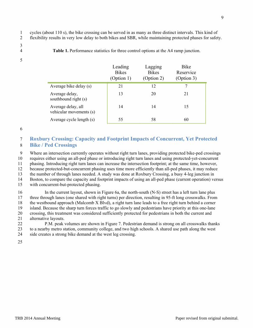
Simulation tests were performed using VISSIM 5.20, using its ring-barrier controller to program 26 signal control logic. Performance statistics are shown in Table 1. Bike delay changes as expected with the 27 three options. In going between option 1 and 2, average delay for bikes and for SBR essentially switch 28 places, depending on which has the favored (lagging) position. In option 3, bike reservice, average bike 29 delay is smallest. SBR delay is unchanged from option 2; however, because the reservice interval is 30 actuated, option 3 provides good protection against long queues developing in the SBR approach lane. 31 Because of the bike phase’s minimum green requirement, giving it a lagging position (options 2 or 3) 32 increases average cycle length by a few seconds, as it can be the constraining factor in switching control 33 back to NBL to start a new cycle. For option 3, the longer cycle length is probably responsible for the 1.5 34 s increase in average delay to vehicular movements. 35
In practice, the intersection runs with option 1 when traffic is heavy, and otherwise runs with an 36 extended version of option 3 in which the bike crossing leads, and after it, SBR and the bike crossing 37 alternate back and forth until WBL begins, after which no further switching is allowed. During long 38
||||
NBT
WBR
SBTNBL
SBR||||
WBL
||||
WBR
reservice
SBR ||||
SBR
Option 3: reservice
Option 2: leading rights
Base Case, using Option 1: lagging rights
TRB 2014 Annual Meeting Paper revised from original submittal.
9
cycles (about 110 s), the bike crossing can be served in as many as three distinct intervals. This kind of 1 flexibility results in very low delay to both bikes and SBR, while maintaining protected phases for safety. 2
3 Table 1. Performance statistics for three control options at the A4 ramp junction. 4
5 Leading
Bikes (Option 1)
Lagging Bikes
(Option 2)
Bike Reservice (Option 3)
Average bike delay (s) 21 12 7
Average delay, southbound right (s)
13 20 21
Average delay, all vehicular movements (s)
14 14 15
Average cycle length (s) 55 58 60
6
Roxbury Crossing: Capacity and Footprint Impacts of Concurrent, Yet Protected 7 Bike / Ped Crossings 8
Where an intersection currently operates without right turn lanes, providing protected bike-ped crossings 9 requires either using an all-ped phase or introducing right turn lanes and using protected-yet-concurrent 10 phasing. Introducing right turn lanes can increase the intersection footprint; at the same time, however, 11 because protected-but-concurrent phasing uses time more efficiently than all-ped phases, it may reduce 12 the number of through lanes needed. A study was done at Roxbury Crossing, a busy 4-leg junction in 13 Boston, to compare the capacity and footprint impacts of using an all-ped phase (current operation) versus 14 with concurrent-but-protected phasing. 15
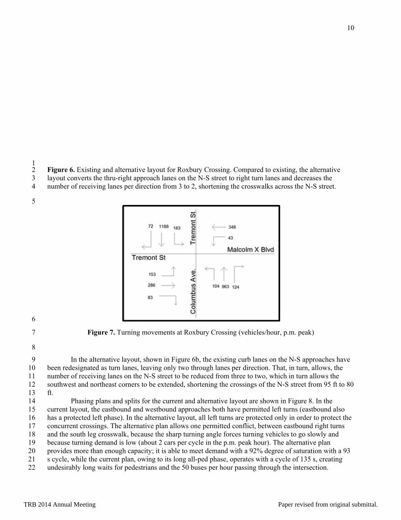
In the current layout, shown in Figure 6a, the north-south (N-S) street has a left turn lane plus 16 three through lanes (one shared with right turns) per direction, resulting in 95-ft long crosswalks. From 17 the westbound approach (Malcomb X Blvd), a right turn lane leads to a free right turn behind a corner 18 island. Because the sharp turn forces traffic to go slowly and pedestrians have priority at this one-lane 19 crossing, this treatment was considered sufficiently protected for pedestrians in both the current and 20 alternative layouts. 21
P.M. peak volumes are shown in Figure 7. Pedestrian demand is strong on all crosswalks thanks 22 to a nearby metro station, community college, and two high schools. A shared use path along the west 23 side creates a strong bike demand at the west leg crossing. 24
25
TRB 2014 Annual Meeting Paper revised from original submittal.
10
1 Figure 6. Existing and alternative layout for Roxbury Crossing. Compared to existing, the alternative 2 layout converts the thru-right approach lanes on the N-S street to right turn lanes and decreases the 3 number of receiving lanes per direction from 3 to 2, shortening the crosswalks across the N-S street. 4
5
6
Figure 7. Turning movements at Roxbury Crossing (vehicles/hour, p.m. peak) 7
8
In the alternative layout, shown in Figure 6b, the existing curb lanes on the N-S approaches have 9 been redesignated as turn lanes, leaving only two through lanes per direction. That, in turn, allows, the 10 number of receiving lanes on the N-S street to be reduced from three to two, which in turn allows the 11 southwest and northeast corners to be extended, shortening the crossings of the N-S street from 95 ft to 80 12 ft. 13
Phasing plans and splits for the current and alternative layout are shown in Figure 8. In the 14 current layout, the eastbound and westbound approaches both have permitted left turns (eastbound also 15 has a protected left phase). In the alternative layout, all left turns are protected only in order to protect the 16 concurrent crossings. The alternative plan allows one permitted conflict, between eastbound right turns 17 and the south leg crosswalk, because the sharp turning angle forces turning vehicles to go slowly and 18 because turning demand is low (about 2 cars per cycle in the p.m. peak hour). The alternative plan 19 provides more than enough capacity; it is able to meet demand with a 92% degree of saturation with a 93 20 s cycle, while the current plan, owing to its long all-ped phase, operates with a cycle of 135 s, creating 21 undesirably long waits for pedestrians and the 50 buses per hour passing through the intersection. 22
TRB 2014 Annual Meeting Paper revised from original submittal.

11
1 a. Existing phasing sequence and splits. 2
3
4 b. Phasing sequence for the alternative layout with protected-concurrent crossing. Splits 5
indicate the minimum needed to achieve a degree of saturation of 0.92, plus (in 6 parentheses) slack time for the non-critical phases. 7
8 Figure 8. Existing and alternative timing plans for Roxbury Crossing. 9
10
Performance of existing and alternative plans, operating with fixed time control, was compared 11 using Synchro and VISSIM. Synchro predicts delay using standard formulas, while VISSIM models 12 traffic in microsimulation. Results are shown in Table 2. The models agree relatively well, with VISSIM 13 predicting lower delays for the northbound and southbound movements in the alternative case. Depending 14 on the model used, the alternative plan lowers average vehicular delay by 11 to 17 s, and reduces 15 pedestrian delay by 22 s. The alternative plan has much to commend it – smaller footprint, shorter 16 pedestrian crossing, less delay for pedestrians and cyclists (which in turn lessens the incentive to non-17
TRB 2014 Annual Meeting Paper revised from original submittal.

12
compliance), and less delay for motorists and transit vehicles. It maintains protected crossings, but allows 1 them to be concurrent with through phases, making more efficient use of time than using an all-pedestrian 2 phase. It alleviates one drawback of the current plan, which is that many pedestrians and cyclists are 3 unwilling to wait for the all-ped phase (the wait for pedestrians could be as great as 128 s) and try to walk 4 or ride with the concurrent phase, creating conflicts with right- and left-turning traffic. 5
6 Table 2. Average user delay (s) for the current versus alternative plan 7
Model Plan Eastbound Westbound Northbound Southbound All
vehiclesAll
peds
Synchro Current 50 58 52 50 51 Alternative 40 35 35 47 40
VISSIM Current 45 61 50 45 49 63 Alternative 39 32 30 32 32 41
8
In a separate analysis, a pair of neighboring intersections along the proposed Casey Arborway in 9 Boston were analyzed to compare the footprint need of the base proposed operating plan, which has 10 concurrent pedestrian crossings with permitted right turn conflicts, with an alternative plan that provides 11 protected-but-concurrent crossings for the seven approaches at the two intersections whose predicted peak 12 hour right turning volumes exceeded 250. The need to consider protected crossings is especially strong 13 for the three crossings that will serve a two-way cycle track as well as pedestrians. Providing all-ped 14 phases was out of the question because of its capacity impact, while protected-yet-concurrent phasing was 15 considered to be contrary to the project goal of minimizing the road footprint because it would require 16 introducing six right turn lanes (one of those approaches was already planned with a right turn lane). 17
However, an analysis using Synchro showed that with right turning traffic diverted to right turn 18 lanes and pedestrian conflicts eliminated, many of the approaches would have sufficient capacity by 19 redesignating the curb lane as a right turn lane without the need for adding a new lane. Considering the 20 eight approaches involved in the two intersections combined, providing protected-yet-concurrent 21 crossings would increase the number of approach lanes by only two, from 24 to 26. This example shows 22 the importance of a combined analysis of spatial layout with signal phasing and timing design, as the 23 signal timing analysis showed that the price of better protected crossings was a much smaller increase in 24 street footprint than previously expected. 25
Conclusion 26
Compared to crossings with permitted conflicts, protected-yet-concurrent phasing offers a means to 27 eliminate conflicts, with a potential increase in safety, with little additional delay to cyclists and 28 pedestrians, though the increase is often small. Factors and tactics that help limit the added delay include 29 having balanced demand between the conflicting right turn and a parallel, protected left turn, having only 30 a few phases in a short cycle, reservice (in a longer cycle), and coordination with one or a few 31 neighboring intersections. With arterial coordination, protected-yet-concurrent phasing adds little delay 32 when the progression speed is close to bike speed, but can add considerable delay when progression speed 33 is considerably faster than bike speed. 34
Because protected-yet-concurrent phasing makes efficient use of time, it is also economical with 35 space. In one example, compared to a solution with an all-ped phase, it needed fewer lanes to serve the 36 traffic; in another, it was found that introducing right turn lanes so that protected-yet-concurrent phasing 37
TRB 2014 Annual Meeting Paper revised from original submittal.

13
could be applied would entail a much smaller than expected increase to the intersection footprint because 1 it allowed several curb lanes to be converted to right turn lanes. 2
Compared to permitted phasing, protected phasing can offer substantial safety and service 3 benefits to pedestrians and especially to cyclists. As more North American cities plan cycle tracks, 4 making good use of protected-yet-concurrent phasing could be important to achieving safety and service 5 objectives while maintaining road capacity and avoiding increasing street footprint. 6
Acknowledgement 7
Rock Miller provided helpful information about signal operations on Long Beach’s 3rd Avenue. 8
References 9
1. Design Manual for Bicycle Traffic. Ede, The Netherlands: CROW, 2007. 10 2. Tian, Z.Z., Urbanik, T., Engelbrecht, R., and Balke, B. Pedestrian Timing Alternatives and Impacts 11
on Coordinated Signal Systems Under Split-Phasing Operations. Transportation Research Record 12 1748, 2001. 13
3. Markenlei. 2011. “Junction design the Dutch – cycle-friendly – way.” Available at 14 http://www.youtube.com/watch?v= FlApbxLz6pA. 15
4. Thompson, S. et. al. Bicycle-Specific Traffic Signals: Results from a State-of-the-Practice Review. 16 Submitted to TRR as paper 13-0536, 2013. 17
5. Monsere, C., M. Figliozzi, and S. Thompson. Operational Guidance for Bicycle-Specific Traffic 18 Signals in the United States: A Review. Interim Report. Portland State University, 2012. 19
6. ITE Pedestrian and Bicycle Council. Separated Bikeways. ITE, 2013. 20 7. Koonce, P., L. Rodegerdts, K. Lee, S. Quayle, S. Beaird, C. Braud, J. Bonneson, P. Tarnoff, and T. 21
Urbanik. Traffic Signal Timing Manual. Report No. FHWA-HOP-08-024. Federal Highway 22 Administration, U.S. Department of Transportation, Washington, D.C., June 2008. 23
8. Koonce, P. J. V, T. Urbanik, and D. Bullock. Evaluation of Diamond Interchange Signal Controller 24 Settings by Using Hardware-in-the-Loop Simulation. Transportation Research Record 1683, 1999, 25 pp. 59-66. 26
9. Taylor, D.B. and H.S. Mahmassani. Coordinating Traffic Signals for Bicycle Progression. 27 Transportation Research Record 1705, 2000, pp. 85-92. 28
10. Littman, M. and P.G. Furth. “Protecting the Bike – Dual Right Turn Lane Conflict in Portland.” 29 sites.google.com/site/studentprojectstraffic/home. 30
TRB 2014 Annual Meeting Paper revised from original submittal.