Embed Size (px)
Citation preview
Dr. Johan H. Enslin, FIEEE, FSAIEE, PrEng
Director, Energy Production and Infrastructure Center (EPIC)
Duke Energy Distinguished Chaired Professor
UNC Charlotte, NC, USA
[email protected] EPIC.UNCC.EDU
Mitigating system impacts
of offshore wind farms
using onshore STATCOMs
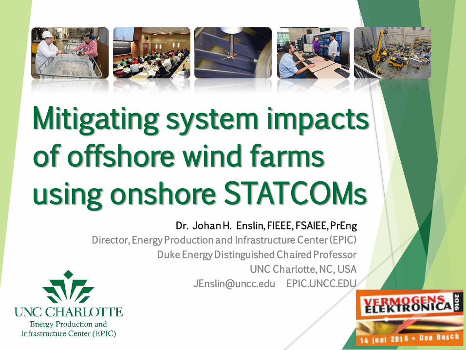
Outline
Development of Off-shore Windfarms (OWF)
Interconnection Options for OWFs
AC Grid Impacts of OWFs
Characteristics of STATCOMs
Case Studies
Conclusions
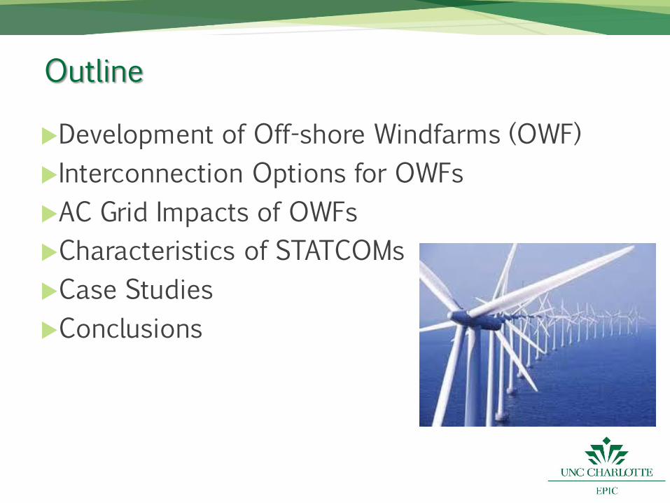
Development of Off-shore Wind Energy
Image Source: Global Wind Energy Council (GWEC-2016) [1]
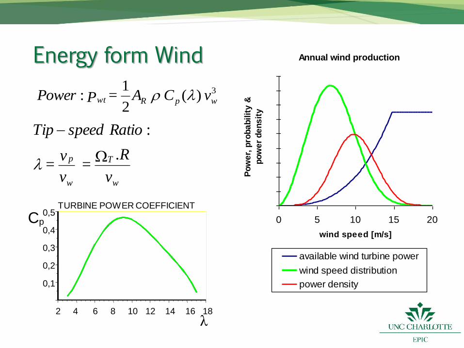
Energy form Wind
3)(2
1: wpRwt v C A = PPower
w
T
w
p
v
.R =
v
v =
RatiospeedTip
:
TURBINE POWER COEFFICIENT
2 4 6 8 10 12 14 16 18
0,1
0,2
0,3
0,4
0,5 C p
Annual wind production
0 5 10 15 20
wind speed [m/s]
Po
we
r, p
rob
ab
ilit
y &
po
we
r d
en
sit
yavailable wind turbine power
wind speed distribution
power density
λ
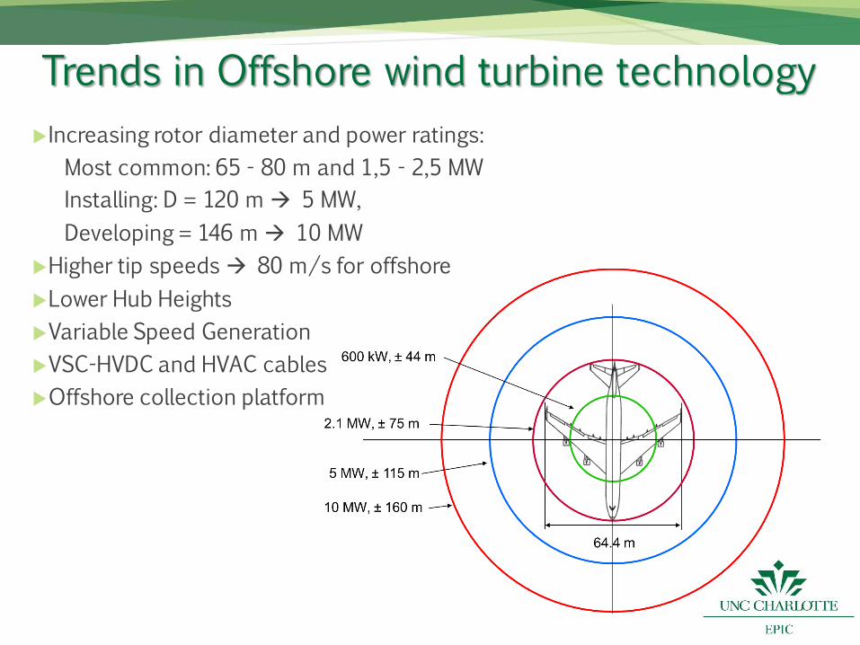
Trends in Offshore wind turbine technology
Increasing rotor diameter and power ratings:
Most common: 65 - 80 m and 1,5 - 2,5 MW
Installing: D = 120 m 5 MW,
Developing = 146 m 10 MW
Higher tip speeds 80 m/s for offshore
Lower Hub Heights
Variable Speed Generation
VSC-HVDC and HVAC cables
Offshore collection platform
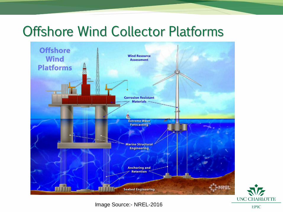
Offshore Wind Collector Platforms
Image Source:- NREL-2016
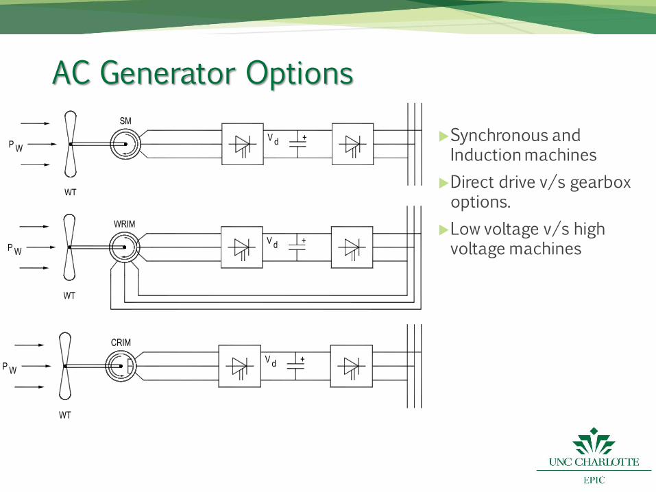
AC Generator Options
Synchronous and Induction machines
Direct drive v/s gearbox options.
Low voltage v/s high voltage machines
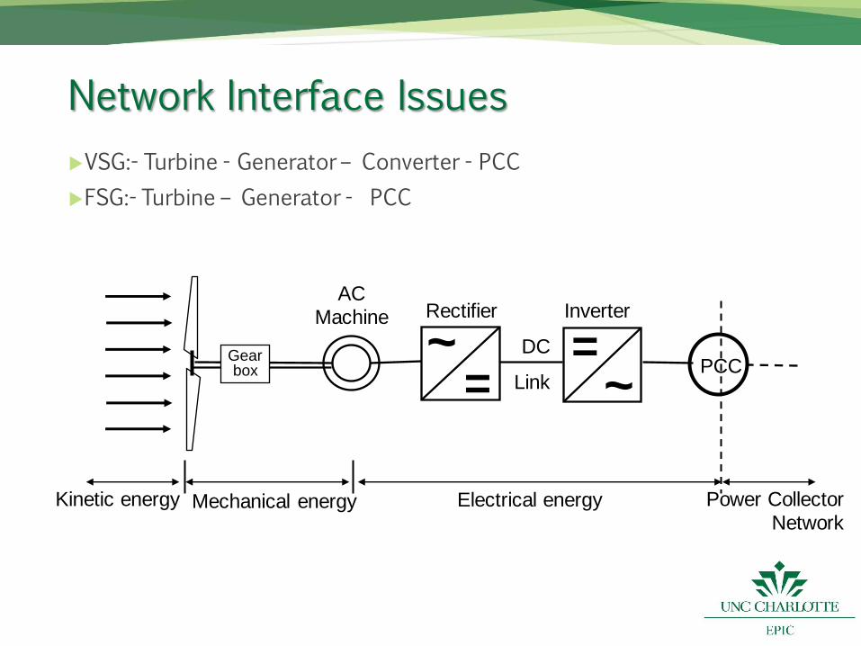
Network Interface Issues
VSG:- Turbine - Generator – Converter - PCC
FSG:- Turbine – Generator - PCC
= ~
= ~ Gear
box
DC
Link
AC Machine
PCC
Kinetic energy Mechanical energy Electrical energy
Rectifier Inverter
Power Collector Network
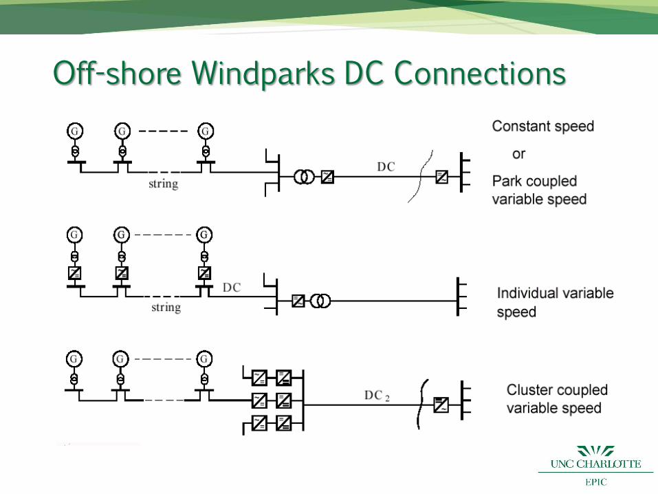
Off-shore Windparks DC Connections
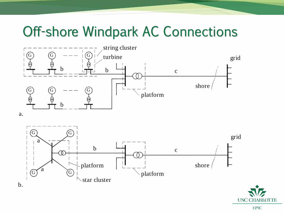
Off-shore Windpark AC Connections
string cluster
shore c b
G G G
b G G G
b turbine grid
platform
star cluster shore
a
a b c
G G
G G platform
grid
a.
b. platform
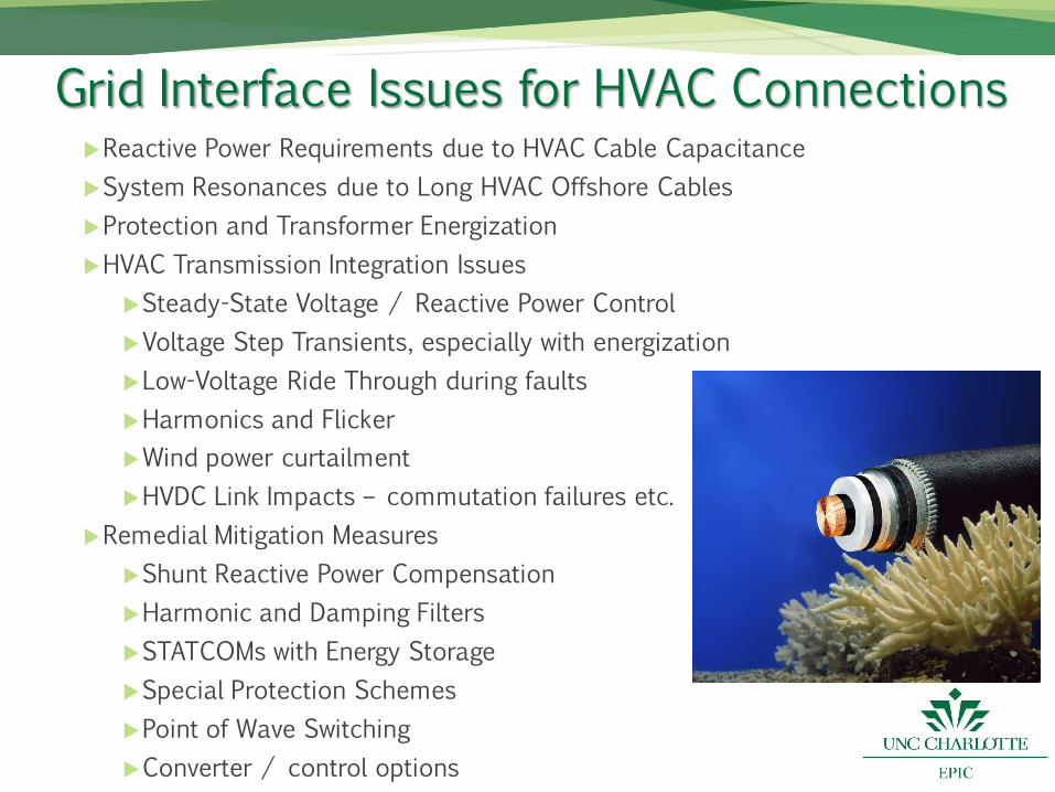
Grid Interface Issues for HVAC Connections Reactive Power Requirements due to HVAC Cable Capacitance
System Resonances due to Long HVAC Offshore Cables
Protection and Transformer Energization
HVAC Transmission Integration Issues
Steady-State Voltage / Reactive Power Control
Voltage Step Transients, especially with energization
Low-Voltage Ride Through during faults
Harmonics and Flicker
Wind power curtailment
HVDC Link Impacts – commutation failures etc.
Remedial Mitigation Measures
Shunt Reactive Power Compensation
Harmonic and Damping Filters
STATCOMs with Energy Storage
Special Protection Schemes
Point of Wave Switching
Converter / control options
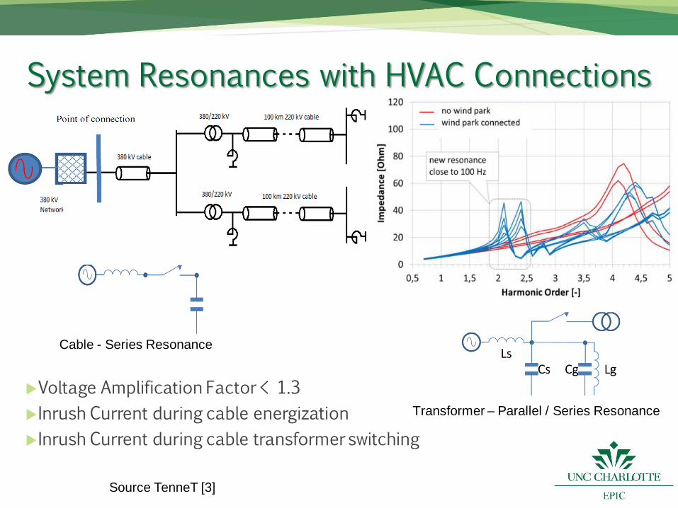
System Resonances with HVAC Connections
Voltage Amplification Factor < 1.3
Inrush Current during cable energization
Inrush Current during cable transformer switching
Cable - Series Resonance
Transformer – Parallel / Series Resonance
Source TenneT [3]
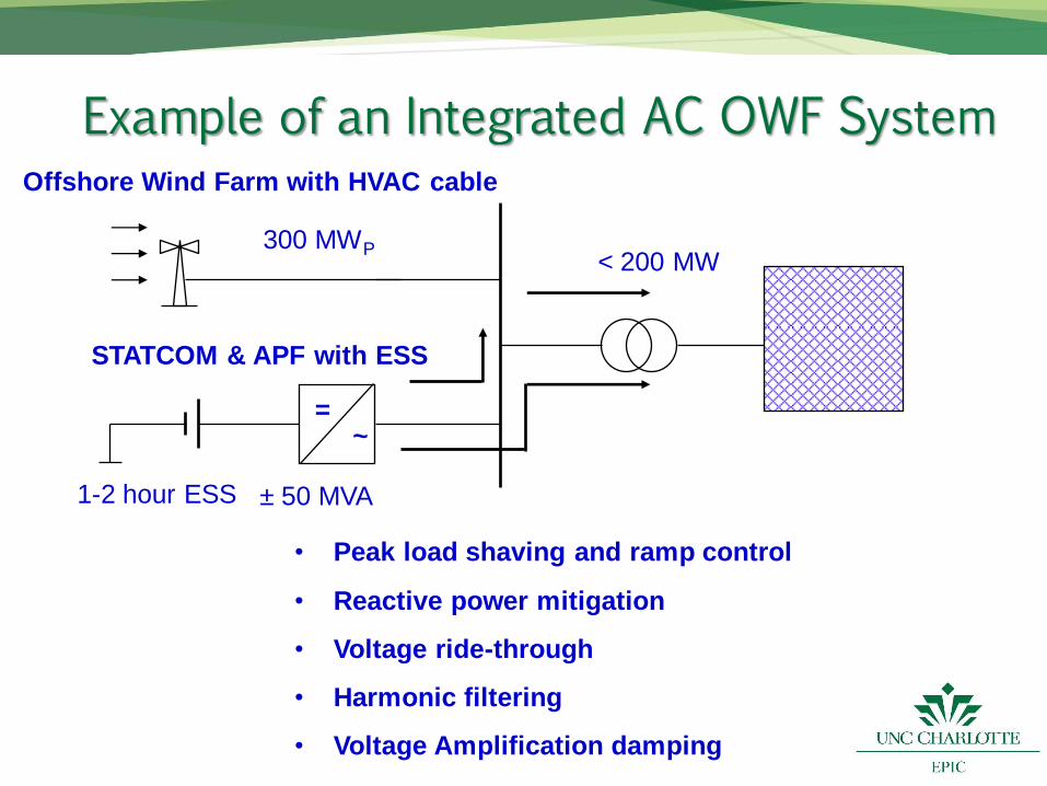
Example of an Integrated AC OWF System
= ~
• Peak load shaving and ramp control
• Reactive power mitigation
• Voltage ride-through
• Harmonic filtering
• Voltage Amplification damping
STATCOM & APF with ESS
< 200 MW
± 50 MVA
300 MWP
1-2 hour ESS
Offshore Wind Farm with HVAC cable
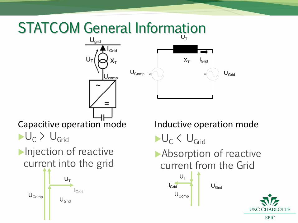
STATCOM General Information
XT
UComp
UT
UGrid
IGrid
AC AC
Capacitive operation mode UC > UGrid
Injection of reactive current into the grid
Inductive operation mode
UC < UGrid
Absorption of reactive current from the Grid
UComp
UT
UGrid
IGrid
UT
UGrid
UComp
IGrid
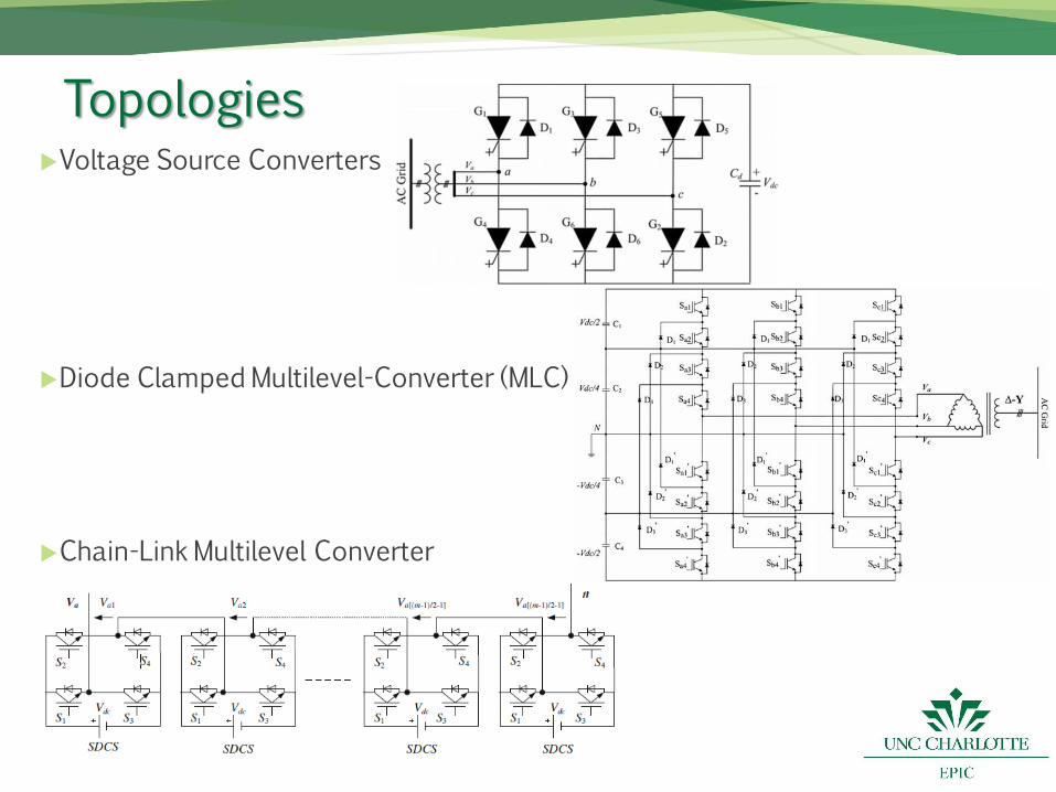
Topologies Voltage Source Converters
Diode Clamped Multilevel-Converter (MLC)
Chain-Link Multilevel Converter
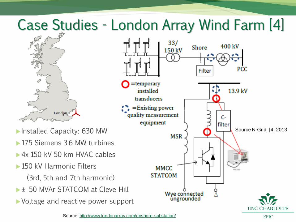
Case Studies - London Array Wind Farm [4]
Source N-Grid [4] 2013 Installed Capacity: 630 MW
175 Siemens 3.6 MW turbines
4x 150 kV 50 km HVAC cables
150 kV Harmonic Filters
(3rd, 5th and 7th harmonic)
± 50 MVAr STATCOM at Cleve Hill
Voltage and reactive power support
Source: http://www.londonarray.com/onshore-substation/
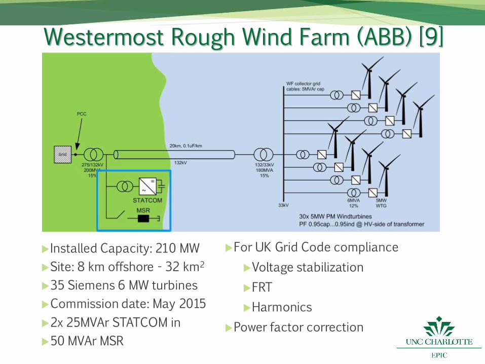
Westermost Rough Wind Farm (ABB) [9]
Installed Capacity: 210 MW
Site: 8 km offshore - 32 km2
35 Siemens 6 MW turbines
Commission date: May 2015
2x 25MVAr STATCOM in
50 MVAr MSR
For UK Grid Code compliance
Voltage stabilization
FRT
Harmonics
Power factor correction
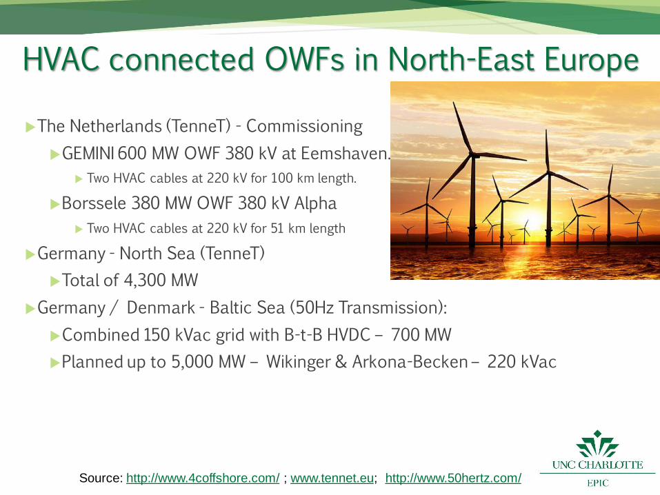
HVAC connected OWFs in North-East Europe
The Netherlands (TenneT) - Commissioning
GEMINI 600 MW OWF 380 kV at Eemshaven.
Two HVAC cables at 220 kV for 100 km length.
Borssele 380 MW OWF 380 kV Alpha
Two HVAC cables at 220 kV for 51 km length
Germany - North Sea (TenneT)
Total of 4,300 MW
Germany / Denmark - Baltic Sea (50Hz Transmission):
Combined 150 kVac grid with B-t-B HVDC – 700 MW
Planned up to 5,000 MW – Wikinger & Arkona-Becken – 220 kVac
Source: http://www.4coffshore.com/ ; www.tennet.eu; http://www.50hertz.com/
Conclusions Large 300 – 800 MW European wind energy projects are currently developed - mostly Offshore
Wind generator ratings are increasing to 5 MW now and 10 MW in the future for offshore applications
Long (50 – 100 km) HVAC cable interconnections are preferred over HVDC due to cost.
Network Interface Issues, including Energization, System Resonances, Power Quality, Reactive Power and Voltage fluctuations are real concern.
Onshore STATCOM and Filter solutions are possible mitigation solution for grid integration.
Future wind farm concepts may include integrated STATCOM and Energy Storage options.
References 1. Global Wind Energy Council (GWEC-2016)
2. Enslin, JHR; Knijp, J; Jansen, CPJ; Schuld, JH: “Impact of Reactive Power Compensation Equipment on the Harmonic Impedance of High Voltage Networks”, IEEE PowerTech-2003, Bologna, Italy, 23-26 June 2003.
3. Jansen; K; Van Hulst, B; Engelbrecht, C; Hesen, P; Velitsikakis, K; Lakenbrink, C: “Resonances due to Long HVAC Offshore Cable Connections: Studies to verify the Immunity of Dutch Transmission network”, in 2015 IEEE PowerTech, Eindhoven, NL 29 June 29 – 2 July 2015.
4. Glasdam, J. B.; Kocewiak, L.; Hjerrild, J.; Bak, C. L.; Zeni, L: “Comparison of Field Measurements and EMT Simulation Results on a Multi-Level STATCOM for Grid Integration of London Array Wind Farm”, Proceedings of the 45th 2014 CIGRE Session, 2014
5. Laouera, M; Mekkaouia, A; Younesb, M: “STATCOM and Capacitor Banks in a fixed-speed wind farm”, TMREES, 2014
6. Saad-Saoud, Z; Lisboa, M; Ekanayake, Jenkins, N; Strbac, G: “Application of STATCOMs to wind farms”, Proc. IEE, Gener. Transm. Distrib., Vol. 145, No. 5, 1998, pp. 511-516
7. Ronner, B; Maibach, P; Thurnherr, T: “Operational experiences of STATCOMs for wind parks” , IET Renew. Power Gener., 2009, Vol. 3, Iss. 3, pp. 349–357
8. http://www.4coffshore.com/
9. http://new.abb.com/docs/librariesprovider78/chile-documentos/jornadas-tecnicas-2013---presentaciones/7-michael-neutz---power-quality.pdf, reviewed: 4/22/2016
10. http://www.energy.siemens.com/us/pool/hq/power-transmission/FACTS/SVC_PLUS_The%20efficient%20Way.pdf, reviewed: 4/22/2016