Embed Size (px)
Citation preview
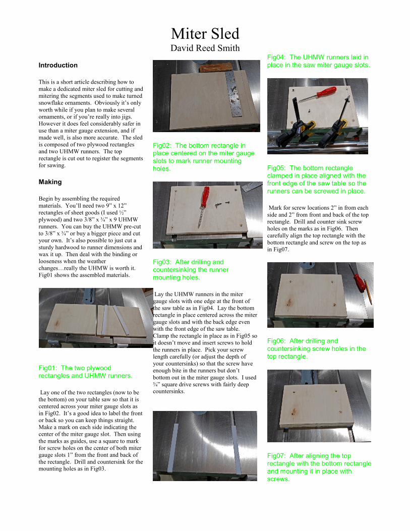
Miter Sled David Reed Smith
Introduction
This is a short article describing how to
make a dedicated miter sled for cutting and
mitering the segments used to make turned
snowflake ornaments. Obviously it’s only
worth while if you plan to make several
ornaments, or if you’re really into jigs.
However it does feel considerably safer in
use than a miter gauge extension, and if
made well, is also more accurate. The sled
is composed of two plywood rectangles
and two UHMW runners. The top
rectangle is cut out to register the segments
for sawing.
Making
Begin by assembling the required
materials. You’ll need two 9” x 12”
rectangles of sheet goods (I used ½”
plywood) and two 3/8” x ¾” x 9 UHMW
runners. You can buy the UHMW pre-cut
to 3/8” x ¾” or buy a bigger piece and cut
your own. It’s also possible to just cut a
sturdy hardwood to runner dimensions and
wax it up. Then deal with the binding or
looseness when the weather
changes…really the UHMW is worth it.
Fig01 shows the assembled materials.
Fig01: The two plywood rectangles and UHMW runners.
Lay one of the two rectangles (now to be
the bottom) on your table saw so that it is
centered across your miter gauge slots as
in Fig02. It’s a good idea to label the front
or back so you can keep things straight.
Make a mark on each side indicating the
center of the miter gauge slot. Then using
the marks as guides, use a square to mark
for screw holes on the center of both miter
gauge slots 1” from the front and back of
the rectangle. Drill and countersink for the mounting holes as in Fig03.
Fig02: The bottom rectangle in place centered on the miter gauge slots to mark runner mounting holes.
Fig03: After drilling and countersinking the runner mounting holes.
Lay the UHMW runners in the miter
gauge slots with one edge at the front of
the saw table as in Fig04. Lay the bottom
rectangle in place centered across the miter
gauge slots and with the back edge even
with the front edge of the saw table.
Clamp the rectangle in place as in Fig05 so
it doesn’t move and insert screws to hold
the runners in place. Pick your screw
length carefully (or adjust the depth of
your countersinks) so that the screw have
enough bite in the runners but don’t
bottom out in the miter gauge slots. I used
¾” square drive screws with fairly deep countersinks.
Fig04: The UHMW runners laid in place in the saw miter gauge slots.
Fig05: The bottom rectangle clamped in place aligned with the front edge of the saw table so the runners can be screwed in place.
Mark for screw locations 2” in from each
side and 2” from front and back of the top
rectangle. Drill and counter sink screw
holes on the marks as in Fig06. Then
carefully align the top rectangle with the
bottom rectangle and screw on the top as in Fig07.
Fig06: After drilling and countersinking screw holes in the top rectangle.
Fig07: After aligning the top rectangle with the bottom rectangle and mounting it in place with screws.
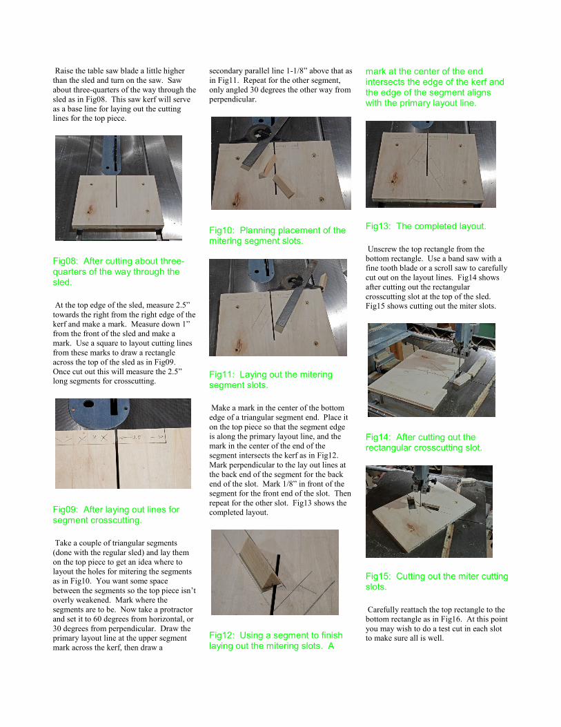
Raise the table saw blade a little higher
than the sled and turn on the saw. Saw
about three-quarters of the way through the
sled as in Fig08. This saw kerf will serve
as a base line for laying out the cutting lines for the top piece.
Fig08: After cutting about three-quarters of the way through the sled.
At the top edge of the sled, measure 2.5”
towards the right from the right edge of the
kerf and make a mark. Measure down 1”
from the front of the sled and make a
mark. Use a square to layout cutting lines
from these marks to draw a rectangle
across the top of the sled as in Fig09.
Once cut out this will measure the 2.5” long segments for crosscutting.
Fig09: After laying out lines for segment crosscutting.
Take a couple of triangular segments
(done with the regular sled) and lay them
on the top piece to get an idea where to
layout the holes for mitering the segments
as in Fig10. You want some space
between the segments so the top piece isn’t
overly weakened. Mark where the
segments are to be. Now take a protractor
and set it to 60 degrees from horizontal, or
30 degrees from perpendicular. Draw the
primary layout line at the upper segment
mark across the kerf, then draw a
secondary parallel line 1-1/8” above that as
in Fig11. Repeat for the other segment,
only angled 30 degrees the other way from
perpendicular.
Fig10: Planning placement of the mitering segment slots.
Fig11: Laying out the mitering segment slots.
Make a mark in the center of the bottom
edge of a triangular segment end. Place it
on the top piece so that the segment edge
is along the primary layout line, and the
mark in the center of the end of the
segment intersects the kerf as in Fig12.
Mark perpendicular to the lay out lines at
the back end of the segment for the back
end of the slot. Mark 1/8” in front of the
segment for the front end of the slot. Then
repeat for the other slot. Fig13 shows the completed layout.
Fig12: Using a segment to finish laying out the mitering slots. A
mark at the center of the end intersects the edge of the kerf and the edge of the segment aligns with the primary layout line.
Fig13: The completed layout.
Unscrew the top rectangle from the
bottom rectangle. Use a band saw with a
fine tooth blade or a scroll saw to carefully
cut out on the layout lines. Fig14 shows
after cutting out the rectangular
crosscutting slot at the top of the sled. Fig15 shows cutting out the miter slots.
Fig14: After cutting out the rectangular crosscutting slot.
Fig15: Cutting out the miter cutting slots.
Carefully reattach the top rectangle to the
bottom rectangle as in Fig16. At this point
you may wish to do a test cut in each slot to make sure all is well.
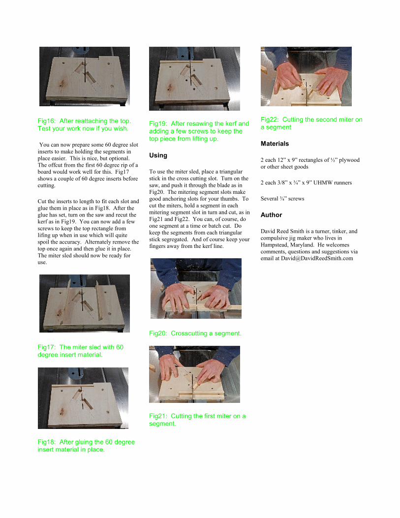
Fig16: After reattaching the top. Test your work now if you wish.
You can now prepare some 60 degree slot
inserts to make holding the segments in
place easier. This is nice, but optional.
The offcut from the first 60 degree rip of a
board would work well for this. Fig17
shows a couple of 60 degree inserts before cutting.
Cut the inserts to length to fit each slot and
glue them in place as in Fig18. After the
glue has set, turn on the saw and recut the
kerf as in Fig19. You can now add a few
screws to keep the top rectangle from
lifing up when in use which will quite
spoil the accuracy. Alternately remove the
top once again and then glue it in place.
The miter sled should now be ready for use.
Fig17: The miter sled with 60 degree insert material.
Fig18: After gluing the 60 degree insert material in place.
Fig19: After resawing the kerf and adding a few screws to keep the top piece from lifting up.
Using
To use the miter sled, place a triangular
stick in the cross cutting slot. Turn on the
saw, and push it through the blade as in
Fig20. The mitering segment slots make
good anchoring slots for your thumbs. To
cut the miters, hold a segment in each
mitering segment slot in turn and cut, as in
Fig21 and Fig22. You can, of course, do
one segment at a time or batch cut. Do
keep the segments from each triangular
stick segregated. And of course keep your
fingers away from the kerf line.
Fig20: Crosscutting a segment.
Fig21: Cutting the first miter on a segment.
Fig22: Cutting the second miter on a segment
Materials
2 each 12” x 9” rectangles of ½” plywood
or other sheet goods
2 each 3/8” x ¾” x 9” UHMW runners
Several ¾” screws
Author
David Reed Smith is a turner, tinker, and
compulsive jig maker who lives in
Hampstead, Maryland. He welcomes
comments, questions and suggestions via email at [email protected]