Embed Size (px)
Citation preview
Mistakes, May 13, 2011 Inside front cover, sba instruction, change PregA to RegA Page iii (preface), 3rd paragraph 2 sentence, change curriculi to curricula Electrical and Computer Engineering curriculi to Electrical and Computer Engineering curricula Section numbers within Section 12.3 are miscounted Page xi, change 12.3.4 to 12.3.2 Page xi, change 12.3.4 to 12.3.3 Page x, section 9.1 heading, change sychronization to synchronization Page xi, heading for section A1.4, change Modifiing to Modifying Page 1, line 8, remove the Once the student truly understands simple concepts, he or she can then embark on the creative process of design, which involves the putting the pieces together to create a more complex system. to Once the student truly understands simple concepts, he or she can then embark on the creative process of design, which involves putting the pieces together to create a more complex system. Page 1, last sentence on page. change Interfacing I/O devices to build embedded systems is presented in Chapters 8, 9, 11, 12, and 13. to Interfacing I/O devices to build embedded systems is presented in Chapters 8, 9, 11, and 12. Page 2, in paragraph after Figure 1.2, delete is, change Read Only Memory, or ROM, is a type of memory where is the information is programmed or burned to Read Only Memory, or ROM, is a type of memory where information is programmed or burned Page 4 (5 lines above Checkpoint 1.2) change One the other hand to On the other hand Page 4, Bottom of page, change An interface is defined as the hardware and software that combine to allow the computer to communicate the external hardware. to An interface is defined as the hardware and software that combine to allow the computer to communicate with the external hardware. Page 5, (3 lines above section 1.2) change An effect approach to building embedded systems to An effective approach to building embedded systems Page 7, Table 1.1. consumer electronics, change camcoder to camcorder.
Page 8: add word “are”, 4 lines above common error, change Functions and procedures are terms used when describing a high-level language, while subroutines often used when describing assembly language. to Functions and procedures are terms used when describing a high-level language, while subroutines are often used when describing assembly language. Page 10, section 1.4, add to, change When the overall task is complete, the join operation causes the friends go away, and I am working alone again. to When the overall task is complete, the join operation causes the friends to go away, and I am working alone again. Page 11, Similarly, if you might read the same page a few times, which is analogous to a program loop. to Similarly, if you might read the same page a few times, which is analogous to a program loop. Page 11, line 10, change look something up in the glossary, then jump back to where you where to look something up in the glossary, then jump back to where you were Page 16, the last sentence of the first full paragraph, change although to though, change If both the external hardware and software program are simulated together, even although the simulated time is slower than the clock on the wall, the real-time hardware/software interactions can be studied. to If both the external hardware and software program are simulated together, even though the simulated time is slower than the clock on the wall, the real-time hardware/software interactions can be studied. Page 16, last paragraph, line 4, add commas. Change In a bottom-up design, one begins with designing building and testing low-level components. to In a bottom-up design, one begins with designing, building, and testing low-level components. Page 17 in the first paragraph under "Successive Refinement" in the third line down, change We begin with set of general specifications to We begin with a set of general specifications Page 19, third line from bottom: change “a” to “an” Although quite real, because there is often not a immediate and direct relationship between a software’s quality and profit, we may be mistakenly tempted to dismiss the importance of quality. to Although quite real, because there is often not an immediate and direct relationship between a software’s quality and profit, we may be mistakenly tempted to dismiss the importance of quality. Page 21, part 4, line 5, misspelled word, change automobilies to automobiles Page 21, add the work not, change
Maintenance Tip: It is better to have a software system that runs slow than one that does run at all.
to
Maintenance Tip: It is better to have a software system that runs slow than one that does not run at all.
Page 23, remove that, change Each tutorial that allows you to have a hands-on experience to support the basic concepts. to Each tutorial allows you to have a hands-on experience to support the basic concepts. Page 24, Homework 1.1, change What is the percentage reduction in power occurring by switching from +5V to +3.3V. to What is the percentage reduction in power occurring by switching from +5V to +3.3V? Page 27, section 1.6, add a, change We begin with set of general specifications, then create a list of requirements and constraints. to We begin with a set of general specifications, then create a list of requirements and constraints. Page 28, 2 lines below Checkpoint 2.1, change Fixed-point numbers will be presented in later in Section 9.1. to Fixed-point numbers will be presented later in Section 9.1. Page 30, lines 8,9 change simplied to simplified Page 30, last line, add to, change Registers A and B are accumulators that can be concatenated together form one 16-bit accumulator, Register D, with Register A containing the most significant byte To Registers A and B are accumulators that can be concatenated together to form one 16-bit accumulator, Register D, with Register A containing the most significant byte Page 31, 7 lines from top of page, change For example, the Z bit is set after an arithmetical or logical operation signify whether or not the result is zero. to For example, the Z bit is set after an arithmetical or logical operation signifying whether or not the result is zero. Page 31, checkpoint 2.9, change question mark to period, change
Checkpoint 2.9: Think about how you could use the “subtract” and the “branch on zero” instructs to test if two numbers are equal?
to Checkpoint 2.9: Think about how you could use the “subtract” and the “branch on zero” instructs to test if two numbers are equal.
Page 32, 4th line from bottom, change A simplified explanation of how processors execute machine code will be presented in later in this chapter. to
A simplified explanation of how processors execute machine code will be presented later in this chapter. Page 33, First paragraph of "2.4 Simplified 9S12 Machine Language Execution". Change The purpose of considering a simplified version to understand in general how a computer a computer executes instructions without being burdened with the extreme complexities that exist in today's high-speed processors. to The purpose of considering a simplified version is to understand in general how a computer a computer executes instructions, without being burdened with the extreme complexities that exist in today's high-speed processors. Page 33, second line from bottom, add it, change TExaS is a co-simulator, meaning simulates both the hardware devices and software action at the same time. to TExaS is a co-simulator, meaning it simulates both the hardware devices and software action at the same time. Page 34, 5 lines after Table 2.5, in two places change arithemetic to arithmetic Page 35, 4 lines above breakout section, change Each bus cycle reads or write one piece of data. to Each bus cycle reads or writes one piece of data. Page 35, 4th line from bottom of second paragraph, just above phase table, add for, change On the real 9S12, read and write cycles can transfer 8-bit or 16-bit data, but this simplified analysis all cycles are 8-bit. to On the real 9S12, read and write cycles can transfer 8-bit or 16-bit data, but for this simplified analysis all cycles are 8-bit. Page 35, Phase 4, change in to is, change It takes a bus cycle to read data from memory, but since registers are inside the processor, no bus cycles occur as data in saved into a register. to It takes a bus cycle to read data from memory, but since registers are inside the processor, no bus cycles occur as data is saved into a register. Page 36, "2.5 Simple Addressing Modes", middle of first paragraph: The data will be a constant, meaning each time that instruction is executed, it will use same data value. to The data will be a constant, meaning each time that instruction is executed, it will use the same data value. Page 37, above checkpoint 2.2, add the, change This execution will also cause the PC to increment to $F003, which will be next instruction. to This execution will also cause the PC to increment to $F003, which will be next the instruction. On page 38, in the line directly above Figure 2.10 change PC equals $F007 to PC equals $F005. Page 38, above checkpoint 2.13, add the, change This execution will also cause the PC to increment to $F005, which will be next instruction.
to This execution will also cause the PC to increment to $F005, which will be next the instruction. Page 39, first line at top, change This execution will also cause the PC to increment to $F008, which will be next instruction. to This execution will also cause the PC to increment to $F008, which will be the next instruction. Page 39, 5 lines below Figure 2.11, change This execution will also cause the PC to increment to $F00A, which will be bra main instruction. to This execution will also cause the PC to increment to $F00A, which will be the bra main instruction. Page 40, top line, change This execution will also cause the PC to change to $F000, which the instruction at main. to This execution will also cause the PC to change to $F000, which is the instruction at main. Page 41, 2 lines above figure 2.12, add is, change Essentially, Metrowerks CodeWarrior is a full-featured commercial product, while TExaS an educational tool. to Essentially, Metrowerks CodeWarrior is a full-featured commercial product, while TExaS is an educational tool. page 41, table at the bottom, change a unsigned to an unsigned twice page 41, table at the bottom, change -32787 to -32768 twice Page 42, remove space between #100, and $3800 in first and third example. change
movb #100, $3800 set RAM to 100 (valid in TExaS). movb #100, $3800 ;set RAM to 100 (valid in CodeWarrior). movb #100, $3800 ;set RAM to 100 (valid in both).
To movb #100,$3800 set RAM to 100 (valid in TExaS). movb #100, $3800 ;set RAM to 100 (valid in CodeWarrior). movb #100,$3800 ;set RAM to 100 (valid in both).
Page 43, Section 2.8, 2nd line, change tool to tools, or i.e., change important conceptual tool because to important conceptual tools because page 44, figures 2.13 and 2.14, change the two flowcharts of Set Flag = 0 to Flag = 1 Page 46. add closing parenthesis to line 7 of section 2.9.2 (the connections are shown as little open circles in Figure 2.16.) Page 48, line lines under checkpoint 2.20, change 1.7 V to 1.6 V. Page 51, last sentence of top paragraph, add does, Although this program not specifically use interrupts
To Although this program does not specifically use interrupts Page 58, 3rd line, change would it to it would Page 59, first line in Section 3.2, delete is, change A Boolean number is has two states. to A Boolean number has two states. Page 68, 5 lines below checkpoint, change The N bit will be set is the result is negative. to The N bit will be set if the result is negative. Page 73, 3 lines above figure 3.10, change But, when the input is low (p=0), the output floats (q=HiZ, which is neither high or low). to But, when the input is low (p=0), the output floats (q=HiZ, which is neither high nor low). Page 73, example 3.6, add “to” two places Change The goal is develop a means for the microcontroller to turn on and turn off an AC-powered appliance. to The goal is to develop a means for the microcontroller to turn on and to turn off an AC-powered appliance. Page 73, example 3.6 problem specification, second sentence. Remove ‘a’, with a control parameters Page 74, 3rd line, change applicance to appliance Page 74, paragraph above figure 3.11 change two places, after figure 3.11 four places flip-flip to flip-flop Page 74, Example 3.6, Program 3.1. change anda #$BF ;PT5 low to anda #$DF ;PT5 low Page 76, two lines above figure 3.14 change flip-flips to flip-flops Page 77, delete this line (this instruction does not exist) asrd ;RegD=RegD/2 Signed shift right Page 81, after example 3.11, change Just like the 8-bit subtraction operators these operators works for both signed and unsigned values. to Just like the 8-bit subtraction operators these operators work for both signed and unsigned values. Page 82, 4 lines above Figure 3.18, change three independent binary inputs each having a significance or 0 or 1. to
three independent binary inputs each having a significance of 0 or 1. Page 83, middle paragraph, 5th line, change italized to italicized Page 83, last line of middle paragraph, change The carry out of bit 7 will be the represent the unsigned overflow for the entire 8-bit addition to The carry out of bit 7 will represent the unsigned overflow for the entire 8-bit addition Page 85, 5th line from top, change italized to italicized Page 85, lines 10 and 11 from the top of the page, change in two places adderess sees to adder sees Page 86, in the 2nd line in the paragraph below the "observation", change The V bit will be set of there to The V bit will be set if there Page 87, paragraph after Observation, add are, change There some instructions that operate only on signed numbers and others that work only for unsigned numbers. to There are some instructions that operate only on signed numbers and others that work only for unsigned numbers. Page 96, Example 3.14. change addd #1265 ;230*N+1265, 0 to 59915 to addd #1265 ;230*N+1265, 1265 to 59915 Page 96, Example 3.14. change idiv ;(230*N+1265)/100, 0 to 599 to idiv ;(230*N+1265)/100, 12 to 599 Page 96, second line from bottom, change constrast to contrast Page 98, the second line at the top, swap row and column, change For example, the letter ‘V’ is in the $50 row and the 6 column. to For example, the letter ‘V’ is in the $50 column and the 6 row. Page 98, 5 lines below checkpoint 3.46, change Unfortunuately to Unfortunately Page 102 in the first paragraph in Section 3.12, change the bold word Instrusiveness to Intrusiveness Page 103, Table T3.1 header, change Fescriptions to Descriptions Page 109, HW3.54, line 3. change You are to design an interface the creates a 4-bit digital signal representing the switch position. to
You are to design an interface that creates a 4-bit digital signal representing the switch position. Page 109, caption for figure Hw3.54, change rotory to rotary Page 112, 2 lines below figure 4.2, change nondivisable to nondivisible Page 116, 2 lines above figure 4.9, change exection to execution Page 118, second line, change addition to additional The ALU calculation may require addition time to execute (e.g., idiv, mem). to The ALU calculation may require additional time to execute (e.g., idiv, mem). Page 118, 4 lines into section 4.1.7, change There is no direction register bits, and these pins are always inputs. to There are no direction register bits; these pins are always inputs. Page 120, just above Example 4.1, remove one In particular, the execution of the second routine one overrides the action of the first routine. to In particular, the execution of the second routine overrides the action of the first routine. Page 122, 12th line of first full paragraph, change actually to actuality In actually, the op code fetches specified as part of an instruction execution are reading the op codes for the next instruction. To In actuality, the op code fetches specified as part of an instruction execution are reading the op codes for the next instruction. Pages 127, 130, 133, figures 4.16, 4.18, and 4.20, change System Intration Module to System Integration Module Page 131. Program 4.3. Change #define PTM _P(0x0258) to #define PTP _P(0x0258) Page 131. Program 4.3. Change DDRH equ $026A ; Direction DDRJ equ $0262 ; Direction to DDRH equ $0262 ; Direction DDRJ equ $026A ; Direction Page 134, 4 lines from the bottom, change a 8-bit to an 8-bit page 135, 3 lines from the bottom of the large paragraph, add on, change a sequential fashion with the smaller addresses the top to a sequential fashion with the smaller addresses on the top Page 136, 3 lines above figure 4.22, change
If one were to pull again from the stack (e.g., execute pula), the 3 would be popped off the stack into Reg A, and 1 would now be on the top of the stack (right-most picture of Figure 4.22). to If one were to pull again from the stack (e.g., execute pula), the 2 would be popped off the stack into Reg A, and 1 would now be on the top of the stack (right-most picture of Figure 4.22). On page 137, in section 4.5, the end of the first line reads, change The timer is essentially a 16-bit counter that incremented at a fixed rate to The timer is essentially a 16-bit counter that is incremented at a fixed rate Page 138, first line below table 4.12 the 9S12DP512 in Figure 4.17 has a default frequency of 8 MHz. to the 9S12DP512 in Figure 4.19 has a default frequency of 8 MHz. page 139, 5th line of solution 4.2, change subrountines to subroutines Page 141, 9 lines from the bottom The RAM contains temporary information that is lost when the power is shunt off (i.e., volatile). to The RAM contains temporary information that is lost when the power is shut off (i.e., volatile). Page 142, section 4.7.1, line 6, Change elasped to elapsed Page 144, Program 4.9 Change elasped to elapsed, four places Page 147, Homework 4.9, two places, change somes to sometimes Page 153, the paragraph above the Common Error The device driver in Example 4.1 is an another example of a module. to The device driver in Example 4.1 is another example of a module. Page 159, first paragraph, first sentence change Typically, hardware modules are at the lowest level, because hardware responses to software. to Typically, hardware modules are at the lowest level, because hardware responds to software. Page 160, section 5.1.5, line 2, change tranverses to traverses Page 160, figure 5.4 caption, change of of to of Page 161, second line from top, change work to works, change The top-down approach work well when an existing operational system is being upgraded or rewritten. to The top-down approach works well when an existing operational system is being upgraded or rewritten. Page 161, 6 lines from the bottom of the page, "strickly" should be spelled "strictly". Page 161, 6 lines from the bottom of the page, possibilites should be spelled possibilities Page 162, 4 lines below the table in the middle of the page, "strickly" should be spelled "strictly". Page 164, first line, change complemenary to complementary
Page 167, change Freescale has a set of instructions convenient for implementating for-loops. To Freescale has a set of instructions convenient for implementing for-loops. Page 174. Section 5.5.1. Sentence 4. add is, Choosing names for variables and functions involves creative thought, and it intimately connected to how we feel about ourselves as programmers. to Choosing names for variables and functions involves creative thought, and it is intimately connected to how we feel about ourselves as programmers. page 175, section 5.5.5.7, , change the case of the first letter specifies whether is the local or global to the case of the first letter specifies whether it is local or global page 175 checkpoint 5.17 change pubic to public Page 181, fourth line of section 5.7.5, add “be” The print statement itself may so slow, that the debugging process itself causes the system to fail. To The print statement itself may be so slow, that the debugging process itself causes the system to fail. Page 185, step 4) change we implement the indefinite loop to we implement the infinite loop Page 185, change Inside the indefinite loop to Inside the infinite loop Page 188, Homework 5.26, change one-wheelled to one-wheeled page 189, problem 5.29 change lines lines to lines page 189, bottom of homework problem 5.29 Describe in general the behavior caused by inserted an fcb $21 into an assembly program. to Describe in general the behavior caused by inserting an fcb $21 into an assembly program. page 189, problem 5.30 change line lines to lines page 189, bottom of homework problem 5.30 Describe in general the behavior caused by inserted to Describe in general the behavior caused by inserting Page 193, section 6.1.1, line 2. Change +127 to +255
Indexed addressing mode uses a fixed offset with the 16-bit registers: X, Y, SP, or PC. The offset can be 5-bit (-16 to +15), 9-bit (-256 to +255), or 16-bit.
Page 194, near bottom, change is to in, The equivalent ROM-based definition is C would be to The equivalent ROM-based definition in C would be Page 198 – 6.1.7 2nd paragraph, 3rd sentence: change The buffers are shown here are uninitialized” to “The buffers shown here are uninitialized.” Page 199 in the second paragraph in section 6.2, change Pointers are usually employed these types of data structures. to Pointers are usually employed in these types of data structures. Page 199, solution to example 6.1, change function to functions. Page 199, word "scare" should be spelled "scarce". RAM is a scare commodity to RAM is a scarce commodity Page 202, 4 lines below Checkpoint 6.7, change sequencially to sequentially Page 205, Program 6.7, add additional comment to line with mul instruction ;Column index J in RegB, Row index I in RegA ;RegX is the base address of M[I,J] Matrix_Read pshb ;Save J on stack ldab #3 ;number of columns mul ;3*I (assume 3*I<256) addb 1,SP+ ;3*I+J ldaa B,X ;read value at M[I,J] rts Program 6.7. Assembly function to access a two by three row-major matrix. Page 209, section 6.5, change Name is a variable length ASCII strings To Name is an ASCII string of variable length Page 211, after Program 6.17, change formated to formatted table, shown in Program 6.18, contains 5 identically formated structures. to table, shown in Program 6.18, contains 5 identically formatted structures. Page 216, section 6.8.1 1st paragraph, 4th sentence: change “This separation makes it is easier to optimize” to “This separation makes it easier to optimize.” Page 216. Middle of 1st paragraph. Remove the a. Change If we can take a complex problem and map it into a FSM model, then we can solve it with a simple FSM software tools. to
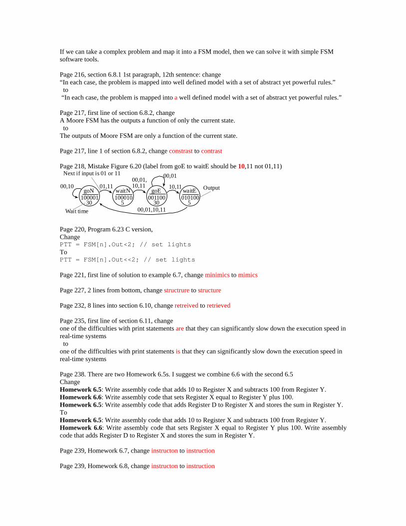
If we can take a complex problem and map it into a FSM model, then we can solve it with simple FSM software tools. Page 216, section 6.8.1 1st paragraph, 12th sentence: change “In each case, the problem is mapped into well defined model with a set of abstract yet powerful rules.” to “In each case, the problem is mapped into a well defined model with a set of abstract yet powerful rules.” Page 217, first line of section 6.8.2, change A Moore FSM has the outputs a function of only the current state. to The outputs of Moore FSM are only a function of the current state. Page 217, line 1 of section 6.8.2, change constrast to contrast Page 218, Mistake Figure 6.20 (label from goE to waitE should be 10,11 not 01,11)
goN
30
Next if input is 01 or 11
100001
Wait time
01,1100,10waitN
5100010
goE
30001100
waitE
5010100
00,01,10,11 10,11
00,01
00,01,10,11
Output
Page 220, Program 6.23 C version, Change PTT = FSM[n].Out<2; // set lights To PTT = FSM[n].Out<<2; // set lights Page 221, first line of solution to example 6.7, change minimics to mimics Page 227, 2 lines from bottom, change structrure to structure Page 232, 8 lines into section 6.10, change retreived to retrieved Page 235, first line of section 6.11, change one of the difficulties with print statements are that they can significantly slow down the execution speed in real-time systems to one of the difficulties with print statements is that they can significantly slow down the execution speed in real-time systems Page 238. There are two Homework 6.5s. I suggest we combine 6.6 with the second 6.5 Change Homework 6.5: Write assembly code that adds 10 to Register X and subtracts 100 from Register Y. Homework 6.6: Write assembly code that sets Register X equal to Register Y plus 100. Homework 6.5: Write assembly code that adds Register D to Register X and stores the sum in Register Y. To Homework 6.5: Write assembly code that adds 10 to Register X and subtracts 100 from Register Y. Homework 6.6: Write assembly code that sets Register X equal to Register Y plus 100. Write assembly code that adds Register D to Register X and stores the sum in Register Y. Page 239, Homework 6.7, change instructon to instruction Page 239, Homework 6.8, change instructon to instruction
Page 240, Homework 6.18, change occurance to occurrence Page 241, Homework 6.19, change period to question mark In particular, how long does it take to call the second subroutine. To In particular, how long does it take to call the second subroutine? Page 257, line 10, change constrast to contrast Page 261, the fourth sentence below checkpoint 7.6 change (add period) An 8-bit push(e.g., psha) creates an unitialized 8-byte local variable, and a 16-bit push(e.g.,pshx) creates and unitialized 16-byte local variable to bit push(e.g., psha) creates an uninitialized 8-bit local variable, and a 16-bit push(e.g.,pshx) creates and uninitialized 16-bit local variable." Page 261, Section 7.3, in the sentence prior to Checkpoint 7.7, should "abibrary" be spelled as "arbitrary"? Page 263, first line under Program 7.2 change implementions to implementations Page 263, first line under Program 7.3 change implementions to implementations Page 263, figure 7.3 change num to sum, in two places Page 263, bottom paragraph line 6, change "at addresses greater or equal to" to "at addresses greater than or equal to". Page 264. The top left box has the line of code "ldd n,x" right before "subd #1". It should be "ldd -2,x" Page 269, program 7.13 comment, 4th line from bottom of page, change a unsigned to an unsigned page 269, Near the middle of the page Change When interrupts are enabled, it is possible have multiple threads active at the same time. to When interrupts are enabled, it is possible to have multiple threads active at the same time. Page 269, in the 2nd paragraph, in the 2nd and 3rd lines, change As we will see later, most high level language generate code that passes the first parameter in a register to As we will see later, most high level languages generate code that passes the first parameter in a register Page 270, program 7.13 comment 5th line from top of page, change 16 nit to 16-bit M set 3 ;M,SP 16 nit M to M set 3 ;M,SP 16-bit M Page 273, line 3 change Because Out will always be less then In, the multiply is 8 by 8 into 16, and the divide is 16 by 16 into 16 bits to Because Out will always be less than In, the multiply is 8 by 8 into 16, and the divide is 16 by 16 into 16 bits Page 278, Homework 7.13, in three places, remove spaces between f and ib in fib
Page 280, Homework 7.20, change PA0 to PT0 Page 281, Lab 7.1 d) Change elasped to elapsed Page 283, Lab 7.2 d) Change elasped to elapsed Page 284 Introduction, change Advances in the number and sophistication of the I/O ports has contributed greatly to the long term growth of applications of embedded systems. to Advances in the number and sophistication of the I/O ports have contributed greatly to the long term growth of applications of embedded systems. Page 284, lines 6-7 of section 8.1, change The RS232 interface using the MAX232 interface in Figure 8.2 is a typical example if this translation. to The RS232 interface using the MAX232 interface in Figure 8.2 is a typical example of this translation. Page 286, 3 lines into section 8.2, change Universal Asychronous Receiver Transmitter to Universal Asynchronous Receiver Transmitter Page 286, correct spelling of reliably, change Engineers have found that one can send data farther, faster, less expensively, and more reliabily using serial versus parallel channels. to Engineers have found that one can send data farther, faster, less expensively, and more reliably using serial versus parallel channels. Page 286, under 8.2.1, in the first line, change Serial transmission involves sending one bit a time to Serial transmission involves sending one bit at a time Page 293, Program 8.1, in comments first line, change in two places Initalize to Initialize Page 294, 11 lines into section 8.3.1, change With SPI, the clock itself can be found in the interface connection between the 9S12 and its periperial. to With SPI, the clock itself can be found in the interface connection between the 9S12 and its peripheral. Page 299, first line into section 8.3.4, change periperials to peripherals Page 301, first line of section 8.4, change comma to period Page 306, 12th line into section 8.6.1, change The 7406 is a digital invertor to The 7406 is a digital inverter Page 306, 14th line into section 8.6.1, change
The TIP120 is a Darlingtion transistor to The TIP120 is a Darlington transistor Page 317, first line of first full paragraph, change labelled to labeled Page 317, Figure 8.26, change right most from Output=1010, to Output=1001 Page 320, 3rd sentence of Homework 8.1, change period to question mark. Page 320, 3rd sentence of Homework 8.2, change period to question mark. Page 320, Homework 8.5, change Assume there is either no keys or one key pressed. to Assume there is either no key or one key pressed. Page 320, Homework 8.6, change Assume there is either no keys or one key pressed. to Assume there is either no key or one key pressed. Page 326, section 9.1 heading, change sychronization to synchronization Page 331, 4 lines from the bottom of the 2nd full paragraph, change A private global variables can be used if an interrupt thread wishes to pass information to itself to A private global variable can be used if an interrupt thread wishes to pass information to itself Page 333, above the 1-9, change (rev revw and wav are interruptable) to (rev revw and wav are interruptible) Page 338, first line, change Everytime to Everytime Page 338, second line after first break, change Everytime to Everytime Page 338, third line under Key Wakeup Interrupts, change Using key wakeup allows make software respond quickly to changes in the external world. to Using key wakeup allows software to respond quickly to changes in the external world. Page 348, first line of solution to example 9.4, change When to With Page 349. Remove "and", change section. Change The second method uses the pulse width modulator (PWM) and previously presented in Section 8.6. to The second method used the pulse width modulator (PWM) previously presented in Section 8.7. Page 351, under Solution, on the 5th to last line in the paragraph, change this solution will will be incorrect to this solution will be incorrect Page 354, first line of solution to Example 9.7, change estable to establish
Page 359, 3rd line from top, change experimently to experimentally Page 365, first line, change active to activate Page 365, Homework 9.4, second line, add period to separate sentences. Page 366 Edit Homework 9.15: Homework 9.15: Assume the PLL is running so the E clock is 25 MHz. Redesign the FSM in Example 6.6 Homework 6.25 to run in the background using input capture and output compare interrupts. The FSM is run whenever there is a rising edge on PT3. There are no backward jumps in the ISR. Change Homework 9.15: Assume the PLL is running so the E clock is 25 MHz. Redesign the FSM in Homework 6.25 to run in the background using input capture and output compare interrupts. The FSM is run whenever there is a rising edge on PT3. There are no backward jumps in the ISR. To Homework 9.15: Assume the PLL is running so the E clock is 25 MHz. Redesign the FSM in Example 6.6 to run in the background using output compare interrupts. There are no backward jumps in the ISR. Page 369, 3 lines from bottom, change Drop-out occurs after a right shift or a divide, and the consequence is that an intermediate result looses its ability to represent all of the values. to Drop-out occurs after a right shift or a divide, and the consequence is that an intermediate result loses its ability to represent all of the values. Page 381. First sentence. Remove the s. Change The two tables consists of multiple unsigned (x,y) pairs, which define a piece-wise linear function. to The two arrays consist of multiple unsigned (x,y) pairs, which define a piece-wise linear function. Page 382, 3 lines above Table 10.3, change paratheses to parentheses Page 386, middle of page, change Everytime to Everytime Page 386, same line as Everytime, change manitissa to mantissa Page 386. Last paragraph. Add occurs. Change Truncation is the error that when a number is converted from one format to another. to Truncation is the error that occurs when a number is converted from one format to another. Page 388, Question 10.3, change period to question mark. Page 388, Question 10.4, change period to question mark. Page 388, Homework 10.8, change a unsigned to an unsigned Page 400, first sentence, add N, change Let N be a m-bit digital output of the computer, hence is an input to the m-bit DAC. to Let N be an m-bit digital output of the computer, hence N is an input to the m-bit DAC. Page 400, add be, change Let the range of the DAC is from Vmin to Vmax. to
Let the range of the DAC be from Vmin to Vmax. Page 400, change An DAC to A DAC, An DAC is monotonic if an increase in digital value always causes an increase in analog value. to A DAC is monotonic if an increase in digital value always causes an increase in analog value. Page 401, caption for Figure 11.5. change controller to controlled Page 404. Second paragraph. First sentence. Add an s to example. Change The example in Programs 11.1 and 11.2 employ the explicit software trigger to start an ADC conversion. to The examples in Programs 11.1 and 11.2 employ the explicit software trigger to start an ADC conversion. Page 404, sixth line from the top, change In this mode, the software starts it, but the ADC sample sequence is repeated over and over continuously. to In this mode, the software starts it, but the ADC sample sequence is continuously repeated. Page 407, At the top of the page under "Solution," change The ADC_In function will perform one conversion, and the returns the 10-bit result to The ADC_In function will perform one conversion and return a 10-bit result Page 404, add to, change The second way trigger the ADC is continuous mode. to The second way to trigger the ADC is continuous mode. Page 407, change. For more noiser situations we can slow down the ADCclock and increase the sampling time. to For situations with more noise we can slow down the ADCclock and increase the sampling time. Page 407, program 11.1, add semicolon after line, change ATD0CTL3 = 0x08 // 1 sample to ATD0CTL3 = 0x08; // 1 sample Page 410, under Solution, starting on the 3rd to last line in the paragraph, change For example, let the voltage slope be 1 V/s, typical set of four voltage measurements might be to For example, letting the voltage slope be 1 V/s, a typical set of four voltage measurements might be Page 413, misspelled word The second parameter is R1, which is choosen large enough to The second parameter is R1, which is chosen large enough Page 413, misspelled word The value of 10 kΩ is choosen slightly smaller than the thermistor resistance at 45 to The value of 10 kΩ is chosen slightly smaller than the thermistor resistance at 45 Page 416, first Action in Tutorial 11, remove period between Tutor11.io and files.
Page 418, Change Homework 11.2 to MAX515 Homework 11.2: The Maxim MAX515 MAX539 is a 1-channel 1012-bit DAC similar to the MAX550. Search the http://www.maxim-ic.com/ web site for a data sheet for the MAX515 MAX539. Show the circuit diagram connecting the DAC chip to an SPI port. Develop DACinit and DACout functions similar to the MAX550 example in the chapter, except the DACout function takes a 1012-bit number in Register D. Change Homework 11.2: The Maxim MAX539 is a 1-channel 12-bit DAC similar to the MAX550. Search the http://www.maxim-ic.com/ web site for a data sheet for the MAX539. Show the circuit diagram connecting the DAC chip to an SPI port. Develop DACinit and DACout functions similar to the MAX550 example in the chapter, except the DACout function takes a 12-bit number in Register D. To Homework 11.2: The Maxim MAX515 is a 1-channel 10-bit DAC similar to the MAX550. Search the http://www.maxim-ic.com/ web site for a data sheet for the MAX515. Show the circuit diagram connecting the DAC chip to an SPI port. Develop DACinit and DACout functions similar to the MAX550 example in the chapter, except the DACout function takes a 10-bit number in Register D. Page 418-9, Change Register A to Register D four places Homework 11.8: Write an assembly language subroutine that samples ADC channel 2 four times, calculates the average of the four samples, and returns the result in Register D A. Homework 11.9: Write an assembly language subroutine that samples all 8 ADC channels, calculates the average of the eight samples, and returns the result in Register D A. Homework 11.10: Write an assembly language subroutine that samples all 8 ADC channels, calculates the minimum and maximum of the eight samples, and returns the range (maximum-minimum) in Register D A. Homework 11.11: Write an assembly language subroutine that samples ADC channels 0,1,2, calculates the median of the three samples, and returns the result in Register D A. Page 419, Change Register A to D, Register B to X Homework 11.14: Assume an AC waveform is connected to analog channel 0. Write an initialization ritual. Write a subroutine that samples the analog input 256 times, and returns the DC amplitude (average) in Register DA, and the AC amplitude (maximum-minimum) in Register X B. Page 423, Lab 11.4, part c), change simple simple to simple Page 425, Lab 11.5, line 6 of part a), change guage to gauge Page 427, Lab 11.6 title, change Acquistion to Acquisition Page 437, 4th line after first break, change simulataneously to simultaneously Page 440, 6 lines above Figure 12.4, change In both cases the data is order-perserving to In both cases the data is order-preserving Section numbers within Section 12.3 are miscounted Page 440, change 12.3.4 to 12.3.2 Page 444, change 12.3.4 to 12.3.3 Page 444, add be, change GetPt points to the data that will be removed by the next call to Fifo_Get, and PutPt points to the empty space where the data will stored by the next call to Fifo_Put. to GetPt points to the data that will be removed by the next call to Fifo_Get, and PutPt points to the empty space where the data will be stored by the next call to Fifo_Put.
Page 446, 6 lines into first paragraph, change retreived to retrieved Page 446, program 12.4, in Fifo_Get, line after ldaa 1,x+ change cpy #Fifo+FIFO_SIZE to cpx #Fifo+FIFO_SIZE Page 447, change has to as, change Maximum disk efficiency occurs only if the disk can continuously read data has the blocks pass under the read head. to Maximum disk efficiency occurs only if the disk can continuously read data as the blocks pass under the read head. Page 470, 3rd line of section 12.9, change stragetic to strategic Page 471, 2nd line, change This global variable to the RAM section. to Add this global variable to the RAM section. Page 471, Action after Question 12.2, change instrustive to intrusive Page 474, remove second both in Homework 12.6, change In particular, both the regular RDRF/SCI interrupt and a TOF periodic timer ISR both call Fifo_Put to enter data into the Fifo. to In particular, both the regular RDRF/SCI interrupt and a TOF periodic timer ISR call Fifo_Put to enter data into the Fifo. Page 474, Homework 12.10 choice f - a period should be at the end of the sentence Page 475, Homework 12.11, add that, change Experimental observations show this to Experimental observations show that this Page 475, Homework 12.12, add that, change Experimental observations show this to Experimental observations show that this Page 475, Homework 12.13, add that, change Experimental observations show this to Experimental observations show that this Page 475, Homework 12.14, add that, change Experimental observations show this to Experimental observations show that this Page 476, last sentence of Homework 12.17, change bandwith to bandwidth
Page 476, last sentence of Homework 12.18, change bandwith to bandwidth Page 476, last sentence of Homework 12.19, change bandwith to bandwidth Page 476, Change Port K to Port J, correct spelling of bandwidth Homework 12.20: Design a simplex communication channel between two 9S12 using the Ports H and J K using FIFO queues and keywakeup interrupts as appropriate. Assume each 9S12 runs a separate initialization routine at about the same time. Write a public function for the transmitter called by the main program to send a byte and a public function for the receiver called by its main program to accept a byte. Package it up into a module hiding the mechanisms from the policies. Estimate the maximum bandwith bandwidth of the channel. Page 476, Lab 12.1 Purpose, change realt-time to real-time Page 485, sentence above Table A1.3, change Some Action menu commands shown in Table A1.3. to Some Action menu commands are shown in Table A1.3. Page 486, 2nd line of Section A1.3, change The requirements of this system is to have each switch control an LED. to A requirement of this system is to have each switch control an LED. Page 486 change If a switch is pressed, the corresponding LED come on. to If a switch is pressed, the corresponding LED should come on. Page 490, heading for section A1.4, change Modifiing to Modifying Page 491, 3rd line of section A1.5, change speadsheet to spreadsheet Page 492, first line, change magneta to magenta Page 496, change An examples of bad comments would be to Examples of bad comments would be Page 496, change An example of good comments would be to Examples of good comments would be Page 498, last sentence, first paragraph, change If neither TheList.rtf or TheLog.rtf exist, then assembly errors are not reported. to If neither TheList.rtf nor TheLog.rtf exists, then assembly errors are not reported. Page 498, change A phasing errors occur when the assembler calculates the size of an instruction different in Pass 2 than previously calculated in Pass 1. to A phasing error occurs when the assembler calculates the size of an instruction differently in Pass 2 than previously calculated in Pass 1.

Page 499, 2 lines above Table A1.7, change Metroworks to Metrowerks Page 499, 1 line above Table A1.7, change are are to are Page 504, 2nd line, change The S9 record is a end of file marker, and sometimes contains the starting address to begin execution. to The S9 record is an end of file marker, and sometimes contains the starting address to begin execution. Page 506, 2nd to last sentence. Add to. Change More complex systems may use frequency, period, phase, or pulse width represent the signals. to More complex systems may use frequency, period, phase, or pulse width to represent the signals. Page 516, data bus, change writen to written Page 516, last line, change unnomalized to unnormalized Page 517 desk check, change final results for a typical inputs. to final results for typical inputs. Page 517, drop out definition, change looses to loses. An error that occurs after a right shift or a divide, and the consequence is that an intermediate result looses its ability to represent all of the values. to An error that occurs after a right shift or a divide, and the consequence is that an intermediate result loses its ability to represent all of the values. Page 518, frame, change occuring to occurring Page 521, loader, change a EEPROM to an EEPROM Page 522 nonreentrant, change A nonreentrant modules to Nonreentrant modules Page 524, PROM, change constrast to contrast Page 525, RAM, change a type of memory where is the information can be stored and retrieved easily and quickly. to a type of memory where the information can be stored and retrieved easily and quickly. Page 525, reentrant, change A reentrant module allow multiple threads to properly execute the desired function. to A reentrant module allows multiple threads to properly execute the desired function. Page 528, unnormalized, change unnomalized to unnormalized Page 530 change
Checkpoint 2.13: ldaa #$32 loads Register A with the value 50. On the other hand, ldaa $36 loads the 8-bit memory contents at address $0032, which happens to be Port K. to Checkpoint 2.13: ldaa #$32 loads Register A with the value 50. On the other hand, ldaa $32 loads the 8-bit memory contents at address $0032, which happens to be Port K. Page 533, change Checkpoint 3.40: -56+64 = 8, so V=0. 200+64 = 264, so C=1 (overflow). N=0 (positive) and Z=0 (not zero). Checkpoint 3.40: -56+64 = 8, so V=0. 200-192 = 8, so C=0. N=0 (positive) and Z=0 (not zero). Page 550, change entry 2N222 to 2N2222 Page 550, Analog-to-Digital converter (ADC), change 299-301 to 398-399 and 403-408 Page 551, under binary actuator, change entry 2N222 to 2N2222 Page 554, under indexed addressing, entry for Load-effective address, page numbers should be 197-198 Page 555, entry for modular programming, recursion page numbers should be 171-172 Page 555, entry for Load-effective address, page numbers should be 197-198 Page 557, entry for recursion page numbers should be 171-172