Embed Size (px)
Citation preview
DRAFT
Missouri Wastewater
Design Guides
January, 2018
Division of Environmental Quality
Water Protection Program

DRAFT Missouri Wastewater Design Guides Acknowledgements
Acknowledgements
i
The Missouri Wastewater Design Guide was developed to serve the citizens and communities in Missouri. This document represents the collective through and expertise of many individuals both within and outside the Department of Natural Resources’ (Department) Water Protection Program. The Department is thankful for the generous assistance from stakeholders representing concerned citizens, government agencies, sewer districts, consulting engineering firms, municipalities, manufacturers, industry representatives, and wastewater treatment professionals. The Missouri Wastewater Design Guide and 10 CSR 20-8 Minimum Design Standards could not been updated or developed without your dedication and participation in over four years of meetings, document review, and sharing of your expertise. Your insights and commitment will provide design guidance to better serve all the communities and citizens of Missouri in the protection of human health, worker safety, and ultimately the water quality. Thank you, Water Protection Program Winter 2018
DRAFT Missouri Wastewater Design Guides Table of Contents
Table of Contents
ii
Acknowledgements .................................................................................................................................................. i Table of Contents .................................................................................................................................................... ii List of Tables & Figures ........................................................................................................................................ vi Introduction ........................................................................................................................................................... vii Glossary ................................................................................................................................................................. ix Abbreviations and Acronyms .............................................................................................................................. xix
Chapter 1: Engineering—Reports, Plans, and Specifications ................................................. 1 1.1 Hydraulic Capacity and Organic Loading ..................................................................................................2 1.2 Engineering Report .....................................................................................................................................7 1.3 Facility Plan ................................................................................................................................................8 1.4 New and Innovative Technology ..............................................................................................................11 1.5 Soils Report ...............................................................................................................................................13 1.6 Summary of Design ..................................................................................................................................15 1.7 Plans ..........................................................................................................................................................16 1.8 Specifications ............................................................................................................................................19 1.9 Revisions to Approved Plans or Specifications ........................................................................................20
Chapter 2: Gravity Sewers ........................................................................................................ 23 2.1 Approval of Sewers...................................................................................................................................23 2.2 Design Capacity and Design Flow ............................................................................................................23 2.3 Details of Design and Construction ..........................................................................................................23 2.4 Manholes ...................................................................................................................................................29 2.5 Inverted Siphons .......................................................................................................................................32 2.6 Sewers in Relation to Streams ..................................................................................................................32 2.7 Aerial Crossings ........................................................................................................................................33 2.8 Protection of Water Supplies ....................................................................................................................34 2.9 Locator Wire .............................................................................................................................................35 2.10 Trenchless Technologies ...........................................................................................................................36
Chapter 3: Alternative Sewer Systems ..................................................................................... 39
3.1 Approval of Sewers...................................................................................................................................39 3.2 Design Capacity and Design Flow ............................................................................................................40 3.3 Supplement to the Engineering Report .....................................................................................................40 3.4 Pressure Sewers ........................................................................................................................................40 3.5 Septic Tank Effluent Pumped (STEP) Sewers..........................................................................................44 3.6 Septic Tank Effluent Gravity (STEG) Sewers ..........................................................................................46 3.7 Commination of Sewers ............................................................................................................................47 3.8 Vacuum Sewers ........................................................................................................................................47
Chapter 4: Pumping Stations .................................................................................................... 49
4.1 Design .......................................................................................................................................................49 4.2 Suction-Lift Pump Stations .......................................................................................................................54 4.3 Submersible Pump Stations ......................................................................................................................55
DRAFT Missouri Wastewater Design Guides Table of Contents
iii
4.4 Screw Pump Stations ................................................................................................................................56 4.5 Alarm Systems ..........................................................................................................................................57 4.6 Emergency Operation ...............................................................................................................................57 4.7 Independent Utility Substations ................................................................................................................60 4.8 Instructions and Equipment ......................................................................................................................60 4.9 Force Mains ..............................................................................................................................................61
Chapter 5: Wastewater Treatment Facilities .......................................................................... 65 5.1 Quality of Effluent ....................................................................................................................................66 5.2 Design .......................................................................................................................................................66 5.3 Details .......................................................................................................................................................68 5.4 Outfalls ......................................................................................................................................................70 5.5 Essential Facilities ....................................................................................................................................71 5.6 Safety ........................................................................................................................................................76 5.7 Chemical Handling ...................................................................................................................................78 5.8 Laboratory Facilities .................................................................................................................................83 5.9 Pump and Haul ..........................................................................................................................................83
Chapter 6: Preliminary Treatment .......................................................................................... 86 6.1 Screening Devices .....................................................................................................................................86 6.2 Comminutors.............................................................................................................................................89 6.3 Grit Removal Facilities .............................................................................................................................90 6.4 Preaeration ................................................................................................................................................92 6.5 Diurnal Flow Equalization ........................................................................................................................93 6.6 Wet Weather Flow Equalization ...............................................................................................................95 6.7 Grease Interceptors ...................................................................................................................................96 6.8 Septage ......................................................................................................................................................98 6.9 Leachate ..................................................................................................................................................100
Chapter 7: Settling ................................................................................................................... 102 7.1 Design .....................................................................................................................................................102 7.2 Sludge and Scum Removal .....................................................................................................................106 7.3 Protective and Service Facilities .............................................................................................................107 7.4 High Rate and Chemically Enhanced Settling ........................................................................................107
Chapter 8: Solids Handing and Disposal ............................................................................... 109
8.1 Sludge Thickeners ...................................................................................................................................110 8.2 Anaerobic Solids Digestion ....................................................................................................................112 8.3 Aerobic Solids Digestion ........................................................................................................................119 8.4 Solids Pumps and Piping ........................................................................................................................123 8.5 Solids Dewatering ...................................................................................................................................124 8.6 Storage ....................................................................................................................................................128 8.7 Chemical Treatment ................................................................................................................................130 8.8 Composting .............................................................................................................................................132 8.9 Biosolids Disposal on Land ....................................................................................................................134 8.10 Other Sludge or Biosolids Disposal Methods .........................................................................................139
DRAFT Missouri Wastewater Design Guides Table of Contents
iv
Chapter 9: Biological Treatment ............................................................................................ 141 9.1 Septic Tanks ............................................................................................................................................141 9.2 Recirculating Media Filters.....................................................................................................................142 9.3 Trickling Filters ......................................................................................................................................146 9.4 Activated Sludge .....................................................................................................................................152 9.5 Oxidation Ditches ...................................................................................................................................159 9.6 Sequencing Batch Reactor (SBR) ...........................................................................................................160 9.7 Membrane Bioreactor (MBR) .................................................................................................................162 9.8 Moving Bed Bioreactor (MBBR) ...........................................................................................................165 9.9 Nutrient Removal ....................................................................................................................................166 9.10 Biological Phosphorus Removal .............................................................................................................167
Chapter 10: Disinfection .......................................................................................................... 169 10.1 Chlorine Disinfection ..............................................................................................................................169 10.2 Dechlorination.........................................................................................................................................174 10.3 Ultraviolet Disinfection ..........................................................................................................................176 10.4 Membrane Bioreactors (MBR) ...............................................................................................................179 10.5 Peracetic Acid .........................................................................................................................................179 10.6 Ozone ......................................................................................................................................................181
Chapter 11: Wastewater Treatment Lagoons and Wastewater Irrigation Alternatives .. 183 11.1 Supplementary Field Survey Data for the Facility Plan .........................................................................183 11.2 Basis of Design .......................................................................................................................................186 11.3 Lagoon Construction Details ..................................................................................................................188 11.4 Lagoon Retrofits .....................................................................................................................................193 11.5 Surface Irrigation of Wastewater ............................................................................................................195 11.6 Subsurface Dispersal Systems ................................................................................................................199 11.7 Low Pressure Pipe Subsurface Systems .................................................................................................200 11.8 Drip Dispersal Subsurface Systems ........................................................................................................203
Chapter 12: Supplemental Treatment ................................................................................... 207 12.1 Post-Aeration ..........................................................................................................................................207 12.2 Polishing Reactors ..................................................................................................................................208 12.3 Filtration ..................................................................................................................................................209 12.4 Microscreening .......................................................................................................................................214 12.5 Chemical Addition ..................................................................................................................................216 12.6 Carbon Adsorption ..................................................................................................................................219 12.7 Side-stream Nutrient Removal ................................................................................................................220 12.8 Diffusers ..................................................................................................................................................220 12.9 Electrocoagulation ...................................................................................................................................221 12.10 Reverse Osmosis ....................................................................................................................................221
Chapter 13: Manure Storage Design Regulations ................................................................ 223 13.1 Permit Application Documents ...............................................................................................................223 13.2 Location ..................................................................................................................................................223 13.3 Manure Storage Structure Sizing ............................................................................................................225
DRAFT Missouri Wastewater Design Guides Table of Contents
v
13.4 Construction of Earthen Basins ..............................................................................................................227 13.5 Construction of Tanks and Pits ...............................................................................................................230 13.6 Construction of Solid Manure Components ...........................................................................................231 13.7 Design and Construction of Pipelines, Pump Stations, and Land Application Systems ........................232 13.8 General System Details ...........................................................................................................................233 13.9 Mortality Management............................................................................................................................234
Chapter 14: Design Requirements for Agrichemical Facilities ........................................... 236 14.1 Exceptions ...............................................................................................................................................236 14.2 Engineering Report .................................................................................................................................236 14.3 Primary Containment for Bulk Agrichemicals for New Construction ...................................................237 14.4 Secondary Containment for Bulk Agrichemicals for New Construction ...............................................239 14.5 Operational Containment for Bulk Liquid Pesticides & Bulk Liquid Fertilizers for New Construction ..........................................................................................................................................................................240 14.6 Operational Containment for Bulk Dry Pesticides & Bulk Dry Fertilizers for New Construction ........241 14.7 Connection to Water Supplies ................................................................................................................242 14.8 Protection from Flooding ........................................................................................................................242 14.9 Emergency and Discharge Response Plan ..............................................................................................242 14.10 Plans .......................................................................................................................................................242 14.11 Specifications .........................................................................................................................................243
Appendices ...........................................................................................................................................................245
Supplemental Summary of Design ..........................................................................................................245 Operation and Maintenance Manual ........................................................................................................253
References ................................................................................................................................................265 Minimum Standards .................................................................................................................................267
DRAFT Missouri Wastewater Design Guides List of Tables & Figures
List of Tables & Figures
vi
Table Page 1-1 Minimum Design Loadings .........................................................................................................................3 1-2 Minimum Population Equivalent .................................................................................................................4 2-1 Minimum Slopes ........................................................................................................................................23 2-2 Steep Slope Protection Spacing .................................................................................................................24 3-1 Approximate Sewer Main Sizes to Serve the Number of EDUs ...............................................................40 5-1 Minimum Separation Distance ..................................................................................................................64 5-2 Piping Color Schemes ................................................................................................................................68 6-1 Grease Production ......................................................................................................................................96 7-1 Minimum Side Water Depth ....................................................................................................................101 7-2 Maximum Primary Settling Tank Surface Overflow Rates .....................................................................102 7-3 Maximum Activated Sludge Final Settling Tank Rates ..........................................................................102 7-4 Maximum Weir Loading Rates ................................................................................................................104 7-5 Minimum Sludge Withdrawal Line Sizes ................................................................................................105 8-1 Typical Physical Characteristics and Quantities of Sludge Produced Based on Wastewater Treatment
Technology ..............................................................................................................................................108 8-2 Minimum Volume per Population Equivalent .........................................................................................120 8-3 Minimum Volume per Population Equivalent per Day ...........................................................................121 8-4 Ceiling Concentration ..............................................................................................................................136 9-1 Particle Size Distribution .........................................................................................................................143 9-2 Trickling Filter Types with Expected Loadings and Removal ................................................................145 9-3 Particle Size Distribution .........................................................................................................................147 9-4 Trickling Filter Dosing Intensity Ranges(SK) .........................................................................................149 9-5 Aeration Rate and Loading Rate Factors .................................................................................................150 9-6 Activated Sludge Process Loadings .........................................................................................................152 9-7 Minimum Oxygen Demand for Activated Sludge Processes ..................................................................154 9-8 Aeration and Mixing Values ....................................................................................................................155 9-9 Sludge Return Rates of Withdrawal ........................................................................................................157 9-10 MBBR Loading Rates ..............................................................................................................................165 10-1 Chlorine Dosages .....................................................................................................................................168 10-2 Dechlorination Dosages ...........................................................................................................................173 11-1 Maximum Allowable Percolation Losses ................................................................................................188 12-1 Ultrafiltration Influent Parameters ...........................................................................................................212 Figure Page G-1 Lagoon Storage Basin Cross Section Terminology ................................................................................. xiii G-2 Trench Cross Section Terminology ........................................................................................................ xvii 5-1 Minimum text for a non-potable water warning sign ................................................................................72 5-2 Minimum text for a fence warning sign .....................................................................................................75 5-3 Sample Text for a Raw Wastewater Label ................................................................................................82 11-1 Counties of Missouri ................................................................................................................................194

DRAFT Missouri Wastewater Design Guides Introduction
Introduction
vii
Historically, the Design Guide was previously adopted in regulation, 10 CSR 20-8, starting in 1979. Since 1979, technology and standards of accepted engineering have progressed to a point that the existing regulations required updating. With the need to update the previously promulgated rules, stakeholder meetings were convened to gain insight and expertise into the standards of practices and the treatment technologies available. Through this process, it was decided that 10 CSR 20-8 needed renamed to reflect its amended regulations, the Minimum Design Standards and this guidance document would be developed. This Missouri Wastewater Design Guide provides guidance for the benefit of Department staff and the designers, owners, and operators of wastewater systems. In this document, items that are in 10 CSR 20-8 are identified with the specific regulatory reference to allow users to cross reference. Items that are present in 10 CSR 20-8 have been identified as the minimum design standards that every facility must meet. The additional components present in this document are to address the best engineering design practices to develop comprehensive and complete technical plans and specifications for the wastewater system. Although this guidance document is not regulation, the technical expertise and regulatory requirements infused into the guidance document will provide consistency with the design and review across the State of Missouri. The Missouri Wastewater Design Guide is not intended to be used as a substitute for engineering experience and judgement nor does it address every situation. Users also should be cognizant of locally adopted regulations or standards that may impact the design of the wastewater system. Criteria contained in this document will be used by the Water Protection Program, in the review of documents submitted pursuant to §644.051, RSMo and 10 CSR 20-6.010. As additional technologies are developed and implemented through the Department’s Innovative Technology Process, those technologies will be included in future revisions to the Missouri Wastewater Design Guide. This document serves as a reference by providing the minimum standards for the design and construction of wastewater systems, in addition to engineering experience and judgement in accordance with standards of practice. It is not reasonable or practical to include all aspects of design in the guide. The goals of this guidance are:
• To ensure that the design of wastewater collection and treatment systems is consistent with public health, worker safety, water quality, and biosolids management objectives.
• To establish a basis for the design and review of technical plans and specifications for wastewater systems.
• To establish the minimum requirements and limiting factors utilized by the Department for review of wastewater system plans and specifications.
• To assist the owner or the design engineer in the preparation of plans, specifications, reports, and other data.
• To guide the Department in the review of technical plans and specifications for determination for the issuance of a construction permit.

DRAFT Missouri Wastewater Design Guides Introduction
viii
Design engineers may provide other basis for design, as long as the designs are justified as standard engineering practice with documentation in the Summary of Design. Additional design references may include, but are not limited to, copies of all ASTM International and American Water Works Association (AWWA) standards pertaining to wastewater systems and appurtenances, design manuals such as Water Environment Federation’s Manuals of Practice (WEF’s MOPs), the American Society of Civil Engineers, the Recommended Standards for Wastewater Facilities (“10 State Standards”), TR-16 Guides for the Design of Wastewater Treatment Works, Department prepared guides, and other wastewater design manuals containing principles of accepted engineering practice. For more information on the wastewater construction permitting process, please visit dnr.mo.gov/env/wpp/permits/ww-construction-permitting.htm. If you have any comments or discover any mistakes in the Design Guide, please email [email protected].

DRAFT Missouri Wastewater Design Guides Glossary
Glossary
ix
Definitions as set forth in the Missouri Clean Water Law and 10 CSR 20-2.010 shall apply to those terms when used in this document, unless the context clearly requires otherwise. Addendum: a document which contains any changes from approved plans or specifications before the contract is awarded. Air-gap separation: a backflow prevention assembly consisting of a physical separation between the free-flowing discharge end of a public water system pipeline and an open or nonpressurized receiving vessel. An approved air-gap separation is at least twice the diameter of the system pipe measuring vertically above the overflow rim of the vessel. In no case is the distance less than one inch (1"). Alternative sewer systems: sewer systems other than conventional gravity sewers which include pressurized sewers carrying raw wastewater from grinder pumps, pressurized or gravity sewers carrying septic tank effluent, and combinations thereof. Although each alternative collection technology uses different motive forces (i.e., pressure, gravity, and vacuum) to move wastewater from its source to its destination, there are many commonalities. Generally, alternative sewer systems use small diameter pipe buried at shallow depths and often contains fewer joints due to increased pipe lengths than conventional gravity sewers. Annular Space: the space between two (2)-cylindrical objects one (1) of which surrounds the other, such as between a casing pipe and a carrier pipe. Antidegradation: the implementation of a rule and procedure approved by the Environmental Protection Agency and the Missouri Clean Water Commission that specifies how the Department will determine, on a case-by-case basis, whether and to what extent, existing water quality may be degraded in a water of the state. The Missouri Antidegradation Implementation Procedure is established in 10 CSR 20-7.031(3)(D). Backflow: the reversal of flow of water or mixtures of water and other substances into the public water system from any source(s). Biochemical Oxygen Demand (BOD): the five (5)-day Biochemical Oxygen Demand (BOD5) is the amount of oxygen needed to stabilize biodegradable organic matter under aerobic conditions within a five (5)-day period.
• Carbonaceous five (5)-day Biochemical Oxygen Demand (CBOD5): BOD5 less the nitrogenous oxygen demand of the wastewater.
• Design average BOD5: generally the average of the organic load received for a continuous twelve (12)-month period for the design year expressed as weight per day. However, the design average BOD5 for facilities having critical operational schedules with high loading periods (e.g., recreational areas, campuses, and industrial facilities) is based on the daily average BOD5 during the seasonal period.
• Design maximum day BOD5: the largest amount of organic load to be received during a continuous twenty-four (24)-hour period expressed as weight per day.
• Design peak hourly BOD5: the largest amount of organic load to be received during a one (1)-hour period expressed as weight per day.
• Total five (5)-day Biochemical Oxygen Demand (TBOD5): equivalent to BOD5 and is sometimes used in order to differentiate carbonaceous plus nitrogenous oxygen demand from strictly carbonaceous oxygen demand.
DRAFT Missouri Wastewater Design Guides Glossary
x
Biosolids: treated sludge that has received an established treatment and is managed in a manner that meets vector attraction reduction and pathogen control, and contains concentrations of regulated pollutants, such that it meets the standards established for use of biosolids for land application, marketing, or distribution. Refer to 40 CFR part 503, February 19, 1993, as published by the EPA Docket Center, EPA West 1301 Constitution Avenue NW., Washington, DC 20004, are incorporated by reference. This document does not incorporate any subsequent amendments or additions.
• Class A biosolids: when pathogens (Salmonella sp. bacteria, enteric viruses, and viable helminth ova) in the biosolids are below detectable levels. Class A corresponds to the existing 40 CFR part 257 “Process to Further Reduce Pathogens (PFRP)” designation.
• Class B Biosolids: when pathogens are detectable but have been reduced to levels that do not pose a threat to public health and the environment as long as actions are taken to prevent exposure to the biosolids after their use or disposal. When Class B biosolids are land applied, there are requirements for the application site; other requirements have to be met when Class B biosolids are surface disposed. Class B corresponds to the existing 40 CFR part 257 “Process to Significantly Reduce Pathogens (PSRP)” designation.
Casing pipe: a pipe with continuous circumferential joints, jacked into position during the boring operation. A casing pipe is most commonly used in underground construction to protect the carrier pipe from damage. Carrier pipe: a sewer piping slipped inside the installed casing pipe. Change order: a document which contains any changes from approved plans or specifications after the contract is awarded. Chlorination: the use of a chlorine solution to disinfect wastewater. Chlorine is an oxidizing disinfectant that kills bacteria. Clarifier: settling tanks with mechanical means for continuous removal of solids being deposited by sedimentation. A clarifier is generally used to remove solid particulates or suspended solids from liquid or clarification or thickening. Sludge collects at the bottom of the tank, or sludge hopper, and is removed. Cleanout: a capped vertical pipe which provides access to a sewer, allowing personnel the ability to clean out blockages in the sewer. Collection system: a network of pipes or similar conduits and all other structures, devices and appurtenances generally excluding service lines and service connections for collecting and conveying wastewater or stormwater to treatment or other disposal facilities. Maintenance and ownership of the collection system is the responsibility of one (1) of the continuing authorities listed in 10 CSR 20-6.010(3)(B). Comminutor: an instrument that cuts and shreds stringy materials and coarse solids into smaller sizes. Construction permit: a written authorization issued by the Department or supervised program authorizing the applicant to construct and modify wastewater components with conditions that are necessary to adequately protect public health and the environment.
DRAFT Missouri Wastewater Design Guides Glossary
xi
Design storage period: The calculated number of days that will fill the manure storage structure from the lower to the upper operating level for a covered storage structure or from the lower to the upper operating level for an uncovered, liquid storage structure during a period of average rainfall minus evaporation (R-E).
• For a design storage period of fewer than three hundred sixty-five (365) days, use the largest consecutive average monthly R-E, corresponding with the number of months of the storage period.
• For multiple storage stages, the storage period is the sum of available storage days in each stage. • For covered liquid manure storage structures, the upper operating level is one foot (1') below the top of
the structure.
Disinfection: a process to remove, deactivate, or kill pathogenic microorganisms. Dry wells: a below-grade structure of a pumping station that contains the pumps, drive shafts, valves, and piping and in which there is no liquid outside the pumps and piping (i.e., the structure is “dry” and personnel often occupy the space). Fats, Oils, and Grease (FOG): animal and plant derived substances that may solidify or become viscous and that separates from wastewater by gravity. FOG in certain amounts will reduce conveyance capacity and create obstructions in the collection system or wastewater treatment facility. Flow:
• Design average flow: the average daily volumes to be received for a continuous twelve (12)-month period expressed as a volume per unit time. However, the design average flow for facilities having critical operational schedules with high hydraulic loading periods (e.g., recreational areas, campuses, and industrial facilities) is based on the daily average flow during the seasonal period.
• Design maximum daily flow: the largest volume of flow to be received during a continuous twenty-four (24)-hour period expressed as a volume per unit time.
• Design peak hourly flow: the largest volume of flow to be received during a one (1)-hour period expressed as a volume per unit time.
• Design peak instantaneous flow: the instantaneous maximum flow rate to be received. Flow equalization: a process of controlling flow rate variations to improve the performance of downstream processes and to reduce the size and cost of downstream wastewater treatment facilities.
• Diurnal flow equalization: provides flow equalization for the dry weather diurnal flow received by a wastewater treatment facility in a twenty-four (24)-hour period.
• Wet weather flow equalization: provides flow equalization during wet weather events which have a hydraulic peak flow greater than the capacity of the wastewater treatment facility.
Force main: a pipe or conduit that conveys wastewater or stormwater under pressure It is considered part of a collection system that is operated and maintained by one of the continuing authorities listed in 10 CSR 20-6.010(3)(B). Freeboard: the vertical distance from the normal operating water surface to the overflow point, spillway, emergency overflow, pipe, or top of the berm or tank, whichever is lowest. Gravity sewer: a pipeline or similar conduit conveying wastewater or treated effluent which flows exclusively under the influence of gravity.
DRAFT Missouri Wastewater Design Guides Glossary
xii
• Interceptor sewer: large sewers that are used to intercept a number of sewer mains or trunk sewers and convey the wastewater to treatment or other disposal facilities. Direct connection of service lines is not recommended for interceptor sewers. An interceptor sewer is considered part of a collection system that is operated and maintained by one (1) of the continuing authorities listed in 10 CSR 20-6.010(3)(B).
• Sewer main: sewers that are used to convey wastewater from generally one (1) or more service lines to trunk sewers or interceptor sewers. A sewer main is considered part of a collection system that is operated and maintained by one (1) of the continuing authorities listed in 10 CSR 20-6.010(3)(B).
• Trunk sewer: large sewers that are used to convey wastewater from sewer mains to interceptor sewers, treatment, or other disposal facilities. A trunk sewer is considered part of a collection system that is operated and maintained by one (1) of the continuing authorities listed in 10 CSR 20-6.010(3)(B)
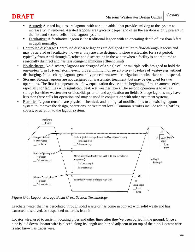
Grease interceptor: a tank that intercepts and collects fats, oils, and grease from a commercial or institutional kitchen waste stream. Grit: includes sand, gravel, cinder, or other heavy solid materials that have a higher specific gravity than the organic biodegradable solids in the wastewater. Grit also includes eggshells, bone chips, seeds, coffee grounds, and large organic particles, such as food waste. Groundwater: the water in subsurface zone of saturation. The water that supplies springs and wells is groundwater. Groundwater table: The seasonal high water level occurring beneath the surface of the ground, including underground watercourses, artesian basins, underground reservoirs and lakes, aquifers, other bodies of water located below the surface of the ground, and water in the saturated zone. For the purposes of this document, groundwater table does not include the perched water table. Holding tank: a watertight tank for temporary storage of wastewater until it can be transported to a permitted wastewater treatment facility. Industrial residuals: solids, residues, and precipitates separated or created by the industrial processes, not including coal combustion residuals. Infiltration/Inflow (I/I): groundwater or stormwater which enters a sanitary sewer system. Karst: a terrain, generally underlain by limestone, in which the topography is chiefly formed by the dissolving of rock and which is commonly characterized by karren, closed depressions, sinkholes, subterranean drainage, and caves. Lagoon: An earthen basin or lined basin used for biological treatment of wastewater, usually designed for biochemical oxygen demand (BOD) removal and settling of solids. Generally, lagoons operate in series with a minimum of three cells to provide treatment. The cells can vary in size and depth; however, the first cell is usually the largest. Lagoons can be designed as flow-through, controlled discharge, no-discharge systems, or for storage. The lagoon cross-section diagram below, Figure G-1, in reference to the different parts of a lagoon cell.
• Flow-through: A flow-through lagoon is a lagoon that is designed to discharge and is usually aerated or facultative.
DRAFT Missouri Wastewater Design Guides Glossary
xiii
� Aerated: Aerated lagoons are lagoons with aeration added that provides mixing to the system to increase BOD removal. Aerated lagoons are typically deeper and often the aeration is only present in the first and second cells of the lagoon system.
� Facultative: A facultative lagoon is the traditional lagoon with an operating depth of less than 8 feet in depth normally.
• Controlled discharge: Controlled discharge lagoons are designed similar to flow-through lagoons and may be aerated or facultative; however they are also designed to store wastewater for a set period, typically from April through October and discharging in the winter when a facility is not required to seasonally disinfect and has less stringent ammonia effluent limits.
• No-discharge: No-discharge lagoons are designed of a single cell or multiple cells designed to hold the one-in-ten (1 in 10)-year storm event, plus a minimum of seventy-five (75)-days of wastewater without discharging. No-discharge lagoons generally precede wastewater irrigation or subsurface soil dispersal.
• Storage: Storage lagoons are not designed for wastewater treatment; but may be designed for two operations. The first is to operate as a flow equalization device at the beginning of the treatment series, especially for facilities with significant peak wet weather flows. The second operation is to act as storage for either wastewater or biosolids prior to land application on fields. Storage lagoons may have less than three cells for operation and may be used in conjunction with other treatment systems.
• Retrofits: Lagoon retrofits are physical, chemical, and biological modifications to an existing lagoon system to improve the design, operations, or treatment level. Common retrofits include adding baffles, covers, or aeration to the lagoon system.
Figure G-1. Lagoon Storage Basin Cross Section Terminology Leachate: water that has percolated through solid waste or has come in contact with solid waste and has extracted, dissolved, or suspended materials from it. Locator wire: used to assist in locating pipes and other lines after they’ve been buried in the ground. Once a pipe is laid down, locator wire is placed along its length and buried adjacent or on top of the pipe. Locator wire is also known as tracer wire.
DRAFT Missouri Wastewater Design Guides Glossary
xiv
Manure: Any form of litter, manure, wastewater, animal mortality byproduct or other organic residuals collected from the production areas of animal feeding operations. Manure storage structure: A fabricated structure or earthen basin used to store manure, litter, and/or process wastewater. Net Positive Suction Head (NPSH): the absolute total dynamic head of the pumped liquid at the suction eye of a pump. Population Equivalent (PE):
• Hydraulic PE: the calculated population which normally contributes the same amount of flow per day. The common base is one hundred (100) gallons per capita per day.
• Organic PE: the calculated population which normally contributes the same amount of BOD5 per day. The common base is 0.22 pounds of BOD5 per capita per day.
Potable water: water which is safe for human consumption in that it is free from impurities in amounts sufficient to cause disease or harmful physiological effects. Precipitation:
• One-in-ten (1:10)-year: the wettest precipitation expected once every ten (10) years for a three hundred sixty-five (365)-day period, based on at least thirty (30) years of records from the National Climatic Data Center.
• Twenty-five (25)-year, twenty-four (24)-hour: the wettest precipitation event for a twenty-four (24)-hour period with a probable recurrence interval of once in twenty-five (25) years based on at least thirty (30) years of records from the National Climatic Data Center.
Process wastes: the waste, wastewater, sludges, biosolids, and residuals which during manufacturing or processing, comes in direct contact with or results from the production or use of any raw material, intermediate product, finished product, by-product, or waste product. Process waste includes but is not limited to waste generated from commercial establishments where the waste is similar in composition to domestic wastewater, but which may have one (1) or more of its constituents exceed typical domestic effluent ranges from a septic tank or other pretreatment component. Pump and haul: a system which temporarily holds domestic or process wastewater; the wastewater is then pumped down and hauled to an appropriate wastewater treatment facility for ultimate disposal. Pump station: designed to move wastewater from lower to higher elevation through pipes or conduits. The key components are pumps, valves, and electrical equipment. A pump station is considered part of a sanitary sewer system that is generally operated and maintained by one of the continuing authorities listed in 10 CSR 20-6.010(3)(B). Rainfall minus evaporation (R-E): The average depth of monthly liquid precipitation minus evaporation as published in the most recent National Weather Service Climate Atlas for the geographical region of the proposed structure. Re-rating: wastewater treatment facility re-rating is the practice of evaluating a facility to assess whether the facility can operate at loading levels higher or lower than the level originally specified during design
DRAFT Missouri Wastewater Design Guides Glossary
xv
Sanitary sewer system: a collection system designed to convey wastewater to treatment or other disposal facilities. Maintenance and ownership of the sanitary sewer system is the responsibility of one (1) of the continuing authorities listed in 10 CSR 20-6.010(3)(B). Screening device: a device which physically removes inorganic objects from wastewater such as rags, paper, plastics, and other such debris to prevent damage and clogging of downstream equipment, piping, and appurtenances. Screenings: rags, toilet paper, disposable wipes, trash, and other large, nuisance inorganic materials in the wastewater. Scum: particles that float to the surface of the liquid. Septage: the liquid and solid material pumped from a septic tank, cesspool, or similar domestic wastewater treatment system, or a holding tank when the system is cleaned or maintained. Service connection: the connection point of the service line and the sanitary sewer system which is operated and maintained by one (1) of the continuing authorities listed in 10 CSR 20-6.010(3)(B). Also, see service line. Service line: a pipe or conduit that conveys wastewater from a building, structure, or dwelling to the service connection. Maintenance and ownership of the service line is generally the responsibility of the property owner. Also, see service connection. Sewer: a pipe or conduit that conveys wastewater or stormwater. Short circuiting: water that moves quickly from the inlet of a structure to the outlet, without properly dispersing. Side water depth: the vertical distance from the top of the overflow weir to the top of the sloped settling floor in circular settling tanks, sludge hopper in rectangular settling tanks, or suction head in suction header settling tanks. Sludge: the solid, semi-solid, or liquid residue removed during the treatment of domestic wastewater in a treatment facility. Sludge includes, but is not limited to; scum or solids removed during primary, secondary, or advanced wastewater treatment processes, septage, and any material derived from sludge. Sludge does not include grit, screenings, industrial residuals, or ash generated during the incineration of sludge. Also, see industrial residuals. Sludge hopper: the lowest point of a settling tank where sludge accumulates and is removed. Solid manure: Manure that can be stacked without free flowing liquids. Spillway: any passageway, channel, or structure, open or closed or both, designated expressly or primarily to discharge excess wastewater from a basin after the water storage elevation has been reached. Static head: the difference in elevation between the surface from which the pump draws wastewater and the surface into which the outlet discharges.
DRAFT Missouri Wastewater Design Guides Glossary
xvi
Storage volume: The volume of manure, runoff, washwater, rainfall, and additional water sources between the lower and upper operating levels. Storm Event:
• Catastrophic storm event: a precipitation event of twenty-four (24)-hour duration that exceeds the twenty-five (25)-year, twenty-four (24)-hour storm event as defined by the most recent publication of the National Weather Service Climate Atlas.
• Chronic weather event: the chronic weather event will be based upon an evaluation of the ten (10)-year return rainfall frequency over a ten (10)-day ninety (90)-day, one hundred eighty (180)-day, and three hundred sixty-five (365)-day operating period. Use of the University of Missouri’s Missouri Climate Center analysis of when a chronic weather event is occurring for any given county in Missouri is preferred.
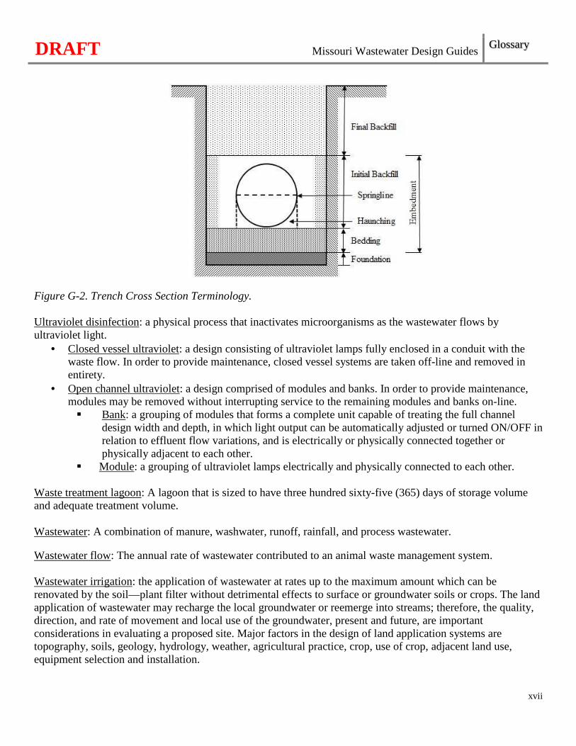
Subsurface soil dispersal: a method of dispersing effluent from a wastewater treatment facility into subsurface soil uniformly and under unsaturated soil conditions allowing for efficient water use and nutrient uptake by vegetation. Supplemental treatment: includes processes and chemicals utilized by a wastewater treatment facility to facilitate operations or to meet effluent limits. This can include tertiary treatment processes, additional preliminary treatment processes, or the addition of chemicals. Total Dynamic Head (TDH): the total head at which a pump operates at any given discharge rate. Total Suspended Solids (TSS): solid particles which remain in suspension in water as a colloid or due to the motion of the water. TSS is the dry-weight of filterable solids particles (including organic and inorganic) dispersed in water. Treatment volume: The permanent volume maintained below the lower pumpdown designed for anaerobic treatment of manure based on latitude. Trench cross section: trench cross section terms are depicted in the following Figure G-2, included herein:
DRAFT Missouri Wastewater Design Guides Glossary
xvii
Figure G-2. Trench Cross Section Terminology. Ultraviolet disinfection: a physical process that inactivates microorganisms as the wastewater flows by ultraviolet light.
• Closed vessel ultraviolet: a design consisting of ultraviolet lamps fully enclosed in a conduit with the waste flow. In order to provide maintenance, closed vessel systems are taken off-line and removed in entirety.
• Open channel ultraviolet: a design comprised of modules and banks. In order to provide maintenance, modules may be removed without interrupting service to the remaining modules and banks on-line. � Bank: a grouping of modules that forms a complete unit capable of treating the full channel
design width and depth, in which light output can be automatically adjusted or turned ON/OFF in relation to effluent flow variations, and is electrically or physically connected together or physically adjacent to each other.
� Module: a grouping of ultraviolet lamps electrically and physically connected to each other. Waste treatment lagoon: A lagoon that is sized to have three hundred sixty-five (365) days of storage volume and adequate treatment volume. Wastewater: A combination of manure, washwater, runoff, rainfall, and process wastewater. Wastewater flow: The annual rate of wastewater contributed to an animal waste management system. Wastewater irrigation: the application of wastewater at rates up to the maximum amount which can be renovated by the soil—plant filter without detrimental effects to surface or groundwater soils or crops. The land application of wastewater may recharge the local groundwater or reemerge into streams; therefore, the quality, direction, and rate of movement and local use of the groundwater, present and future, are important considerations in evaluating a proposed site. Major factors in the design of land application systems are topography, soils, geology, hydrology, weather, agricultural practice, crop, use of crop, adjacent land use, equipment selection and installation.
DRAFT Missouri Wastewater Design Guides Glossary
xviii
Wastewater reuse: (i.e., reclaimed or recycled water) is the process of converting wastewater into water that can be reused for other purposes. Reuse may include replenishing surface water and groundwater. Reused water may also be directed toward fulfilling certain needs in residences (e.g. toilet flushing), businesses, and industry. Wastewater Treatment System:
• Centralized: a single sewer system and treatment facility under common ownership and management for an entire community or development.
• Decentralized: wastewater treatment systems used to collect, treat, and disperse or reclaim domestic wastewater from individual homes, clusters of homes, buildings, or isolated communities at or near the point of waste generation. � Individual onsite wastewater treatment system. A system relying on natural processes and/or
mechanical components serving one dwelling or building treating with or without dispersing into the soil onsite.
� Cluster wastewater treatment system. A wastewater collection and treatment system under some form of common ownership which collects wastewater from two or more independent dwellings or buildings but not the entire community or development and conveys it to a treatment and dispersal system located near the dwellings or buildings.
Water supply source: all sources of water supply including wells, infiltration galleries, springs, reservoirs, lakes, streams, or rivers from which water is derived for public water systems, including the structures, conduits, pumps, and appurtenances used to withdraw water from the source or to store or transport water to the water treatment facility or water distribution system. Watertight: condition ascribed to a device that is constructed so that no water can move into or out of it except by design through inlets and outlets Wet well: a below-grade structure of a pumping station into which the liquid flows and from which the pumps draw suction.
DRAFT Missouri Wastewater Design Guides Abbreviations and Acronyms
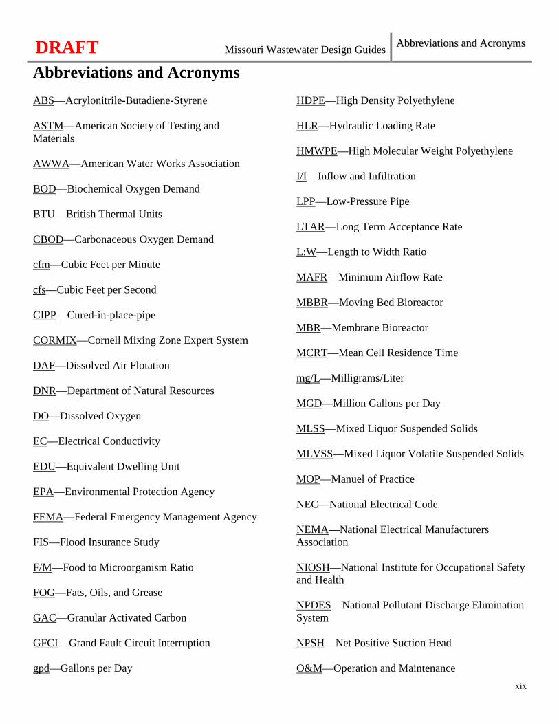
Abbreviations and Acronyms
xix
ABS—Acrylonitrile-Butadiene-Styrene ASTM—American Society of Testing and Materials AWWA—American Water Works Association BOD—Biochemical Oxygen Demand BTU—British Thermal Units CBOD—Carbonaceous Oxygen Demand cfm—Cubic Feet per Minute cfs—Cubic Feet per Second CIPP—Cured-in-place-pipe CORMIX—Cornell Mixing Zone Expert System DAF—Dissolved Air Flotation DNR—Department of Natural Resources DO—Dissolved Oxygen EC—Electrical Conductivity EDU—Equivalent Dwelling Unit EPA—Environmental Protection Agency FEMA—Federal Emergency Management Agency FIS—Flood Insurance Study F/M—Food to Microorganism Ratio FOG—Fats, Oils, and Grease GAC—Granular Activated Carbon GFCI—Grand Fault Circuit Interruption gpd—Gallons per Day
HDPE—High Density Polyethylene HLR—Hydraulic Loading Rate HMWPE—High Molecular Weight Polyethylene I/I—Inflow and Infiltration LPP—Low-Pressure Pipe LTAR—Long Term Acceptance Rate L:W—Length to Width Ratio MAFR—Minimum Airflow Rate MBBR—Moving Bed Bioreactor MBR—Membrane Bioreactor MCRT—Mean Cell Residence Time mg/L—Milligrams/Liter MGD—Million Gallons per Day MLSS—Mixed Liquor Suspended Solids MLVSS—Mixed Liquor Volatile Suspended Solids MOP—Manuel of Practice NEC—National Electrical Code NEMA—National Electrical Manufacturers Association NIOSH—National Institute for Occupational Safety and Health NPDES—National Pollutant Discharge Elimination System NPSH—Net Positive Suction Head O&M—Operation and Maintenance
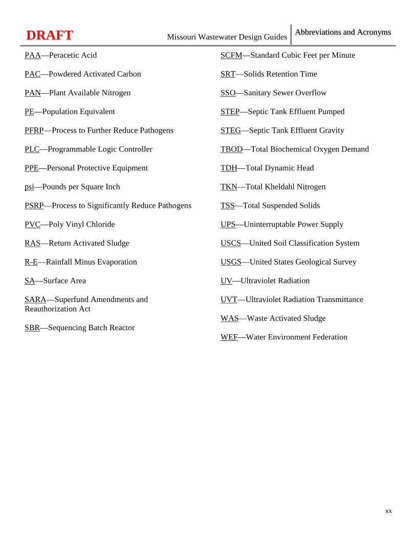
DRAFT Missouri Wastewater Design Guides Abbreviations and Acronyms
xx
PAA—Peracetic Acid PAC—Powdered Activated Carbon PAN—Plant Available Nitrogen PE—Population Equivalent PFRP—Process to Further Reduce Pathogens PLC—Programmable Logic Controller PPE—Personal Protective Equipment psi—Pounds per Square Inch PSRP—Process to Significantly Reduce Pathogens PVC—Poly Vinyl Chloride RAS—Return Activated Sludge R-E—Rainfall Minus Evaporation SA—Surface Area SARA—Superfund Amendments and Reauthorization Act SBR—Sequencing Batch Reactor
SCFM—Standard Cubic Feet per Minute SRT—Solids Retention Time SSO—Sanitary Sewer Overflow STEP—Septic Tank Effluent Pumped STEG—Septic Tank Effluent Gravity TBOD—Total Biochemical Oxygen Demand TDH—Total Dynamic Head TKN—Total Kheldahl Nitrogen TSS—Total Suspended Solids UPS—Uninterruptable Power Supply USCS—United Soil Classification System USGS—United States Geological Survey UV—Ultraviolet Radiation UVT—Ultraviolet Radiation Transmittance WAS—Waste Activated Sludge WEF—Water Environment Federation

DRAFT Engineering—Reports, Plans, and Specifications 1
Chapter 1: Engineering—Reports, Plans, and Specifications
1
Engineering Services. Engineering services are performed in three (3) steps—
1. Engineering report or facility plan; 2. Preparation of construction plans and specifications; and 3. Contractual documents, construction compliance, inspection, administration, and acceptance. It is in the
owner’s interest to work with the engineer and contractor on the expectations and scope of work early in the process of drafting these documents.
The Missouri Wastewater Design Guides covers the items in the first and second steps above. Submittal. Engineering reports or facility plans must be approved by the Department prior to the submittal of the plans, specifications, and the appropriate permit applications and fees [See 10 CSR 20-8.110(2)(A)]. Engineering Reports or Facility Plans.
• Engineering reports shall be completed for projects involving collection systems, pumping stations, and force mains [See 10 CSR 20-8.110(2)(B)1.].
• Facility plans shall be completed for projects involving wastewater treatment facility projects and projects receiving Department funding through the grant and loan programs under 10 CSR 20-4, Grants and Loans [See 10 CSR 20-8.110(2)(B)2.]. For federal or state financed grant or loan projects, additional requirements may apply.
• An engineering report or facility plan— � Identifies and evaluates wastewater related problems; � Assembles basic information; � Presents criteria and assumptions; � Examines project alternatives (with preliminary layouts and cost estimates); � Describes system reliability for each unit operation with the largest unit out-of-service; � Describes financing methods; � Sets forth anticipated user charges; � Reviews organizational and staffing requirements; � Offers a conclusion with a proposed project for client consideration; and � Outlines official actions; time schedules and procedures to implement the project.
• The concept (including process description and sizing), factual data, and controlling assumptions and considerations for the functional planning of wastewater facilities are presented for each process unit and for the whole system. These data form the continuing technical basis for the detailed design and preparation of construction plans and specifications.
• Architectural, structural, mechanical, and electrical designs are usually excluded. Sketches may be desirable to aid in presentation of a project. Outline specifications of process units, special equipment, etc., are occasionally included.
Approval. No approval for construction shall be issued until final detailed plans and specifications are signed, sealed, and dated by a Missouri registered professional engineer, submitted, and found to be satisfactory by the Department [See 10 CSR 20-8.110(2)(C)]. Pre-Design Meeting. A pre-design meeting is recommended for wastewater treatment facility projects with the applicant, design engineer, and Department in attendance to discuss alternative evaluations, changes in scope of
DRAFT Engineering—Reports, Plans, and Specifications 1
2
work, requests for designs based on equivalent criteria, schedule of submittal and review, and applicable reliability guidelines.
1.1 Hydraulic Capacity and Organic Loading 1.1.1 Existing Systems Hydraulic capacity for wastewater facilities to serve existing collection systems. Projections shall be made from actual flow data to the extent possible using no less than one (1) year of data [See 10 CSR 20-8.110(3)(A)1.].
• Evaluate the probable degree of accuracy of data and projections for all critical design flow conditions. Include this confidence estimation evaluation of the accuracy of existing data and an evaluation of the confidence of estimates of flow reduction anticipated due to infiltration/inflow (I/I) reduction or flow increases due to elimination of sanitary sewer overflows, backups, or hydraulic restrictions. Consider design precipitation events with representative runoff characteristics and groundwater elevations to ensure a higher degree of accuracy when estimating I/I reduction.
• Include critical data and methodology used in the evaluation. Include graphical displays of critical peak wet weather flow data (e.g., design maximum day flow, design peak hourly flow, and design peak instantaneous flow) for a sustained wet weather flow period of significance to the project.
Combined sewer interceptors. In addition to the above requirements, interceptor sewers for combined sewers shall have capacity to receive a sufficient quantity of combined wastewater for transport to treatment facilities to ensure attainment of the appropriate water quality standards [See 10 CSR 20-8.110(3)(A)2.]. Design of organic capacity of wastewater treatment facilities to serve existing collection systems. Projections shall be made from actual waste load data to the extent possible using no less than one (1) year of data [See 10 CSR 20-8.110(3)(A)3.].
• Compare projections to those described in subsection 1.1.2 and make an accounting for significant variations from those values.
• Evaluate the probable degree of accuracy of data and projections for all critical design organic conditions.
• Septage and leachate may contribute significant organic load and other materials which can cause operational problems and non-compliance with NPDES permit limitations. When septage or leachate is to be discharged to the wastewater treatment facility, consult with the Department. Refer to sections 6.8 and 6.9.
Industrial sources. A list of industrial sources and their documented hydraulic and organic contributions shall be submitted to the Department [See 10 CSR 20-8.110(3)(A)4.]. 1.1.2 New Systems Hydraulic capacity for wastewater facilities to serve new collection systems. Flow estimates shall be identified for the design average flow and design peak hourly flow based on the design year and used as a
DRAFT Engineering—Reports, Plans, and Specifications 1
3
basis for the design of sewers, pump stations, and wastewater treatment facilities [See 10 CSR 20-8.110(3)(B)1.].
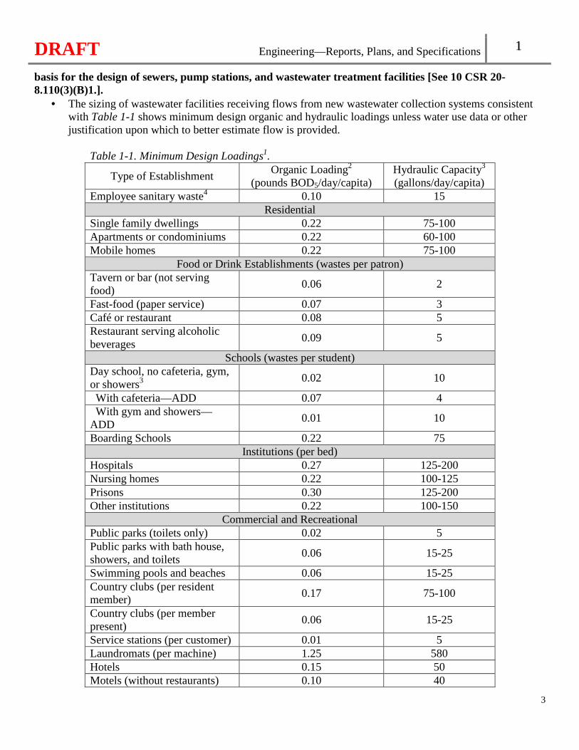
• The sizing of wastewater facilities receiving flows from new wastewater collection systems consistent with Table 1-1 shows minimum design organic and hydraulic loadings unless water use data or other justification upon which to better estimate flow is provided.
Table 1-1. Minimum Design Loadings1.
Type of Establishment Organic Loading2
(pounds BOD5/day/capita) Hydraulic Capacity3 (gallons/day/capita)
Employee sanitary waste4 0.10 15 Residential
Single family dwellings 0.22 75-100 Apartments or condominiums 0.22 60-100 Mobile homes 0.22 75-100
Food or Drink Establishments (wastes per patron) Tavern or bar (not serving food)
0.06 2
Fast-food (paper service) 0.07 3 Café or restaurant 0.08 5 Restaurant serving alcoholic beverages
0.09 5
Schools (wastes per student) Day school, no cafeteria, gym, or showers3
0.02 10
With cafeteria—ADD 0.07 4 With gym and showers—ADD
0.01 10
Boarding Schools 0.22 75 Institutions (per bed)
Hospitals 0.27 125-200 Nursing homes 0.22 100-125 Prisons 0.30 125-200 Other institutions 0.22 100-150
Commercial and Recreational Public parks (toilets only) 0.02 5 Public parks with bath house, showers, and toilets
0.06 15-25
Swimming pools and beaches 0.06 15-25 Country clubs (per resident member)
0.17 75-100
Country clubs (per member present)
0.06 15-25
Service stations (per customer) 0.01 5 Laundromats (per machine) 1.25 580 Hotels 0.15 50 Motels (without restaurants) 0.10 40
DRAFT Engineering—Reports, Plans, and Specifications 1
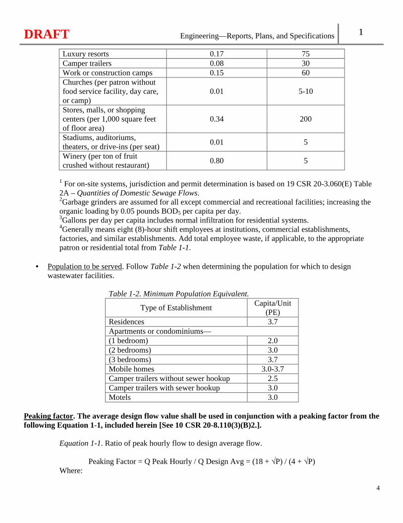
4
Luxury resorts 0.17 75 Camper trailers 0.08 30 Work or construction camps 0.15 60 Churches (per patron without food service facility, day care, or camp)
0.01 5-10
Stores, malls, or shopping centers (per 1,000 square feet of floor area)
0.34 200
Stadiums, auditoriums, theaters, or drive-ins (per seat)
0.01 5
Winery (per ton of fruit crushed without restaurant)
0.80 5
1 For on-site systems, jurisdiction and permit determination is based on 19 CSR 20-3.060(E) Table 2A – Quantities of Domestic Sewage Flows. 2Garbage grinders are assumed for all except commercial and recreational facilities; increasing the organic loading by 0.05 pounds BOD5 per capita per day. 3Gallons per day per capita includes normal infiltration for residential systems. 4Generally means eight (8)-hour shift employees at institutions, commercial establishments, factories, and similar establishments. Add total employee waste, if applicable, to the appropriate patron or residential total from Table 1-1.
• Population to be served. Follow Table 1-2 when determining the population for which to design wastewater facilities.
Table 1-2. Minimum Population Equivalent.
Type of Establishment Capita/Unit
(PE) Residences 3.7 Apartments or condominiums— (1 bedroom) 2.0 (2 bedrooms) 3.0 (3 bedrooms) 3.7 Mobile homes 3.0-3.7 Camper trailers without sewer hookup 2.5 Camper trailers with sewer hookup 3.0 Motels 3.0
Peaking factor. The average design flow value shall be used in conjunction with a peaking factor from the following Equation 1-1, included herein [See 10 CSR 20-8.110(3)(B)2.].
Equation 1-1. Ratio of peak hourly flow to design average flow.
Peaking Factor = Q Peak Hourly / Q Design Avg = (18 + √P) / (4 + √P) Where:
DRAFT Engineering—Reports, Plans, and Specifications 1
5
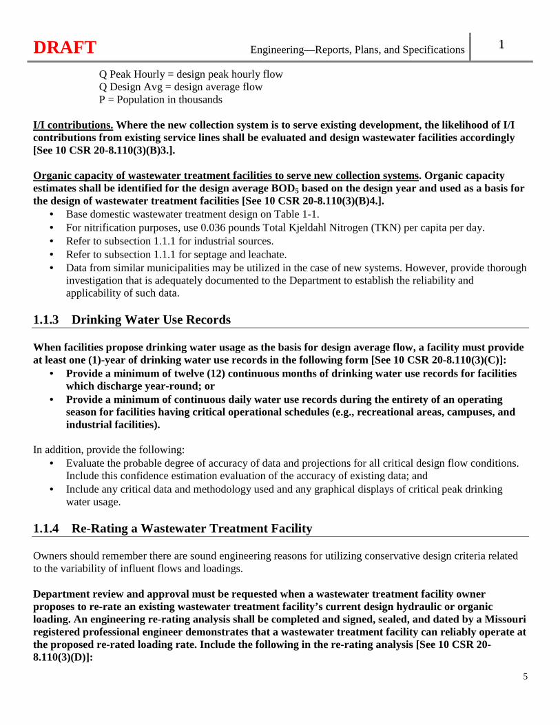
Q Peak Hourly = design peak hourly flow Q Design Avg = design average flow P = Population in thousands
I/I contributions. Where the new collection system is to serve existing development, the likelihood of I/I contributions from existing service lines shall be evaluated and design wastewater facilities accordingly [See 10 CSR 20-8.110(3)(B)3.]. Organic capacity of wastewater treatment facilities to serve new collection systems. Organic capacity estimates shall be identified for the design average BOD5 based on the design year and used as a basis for the design of wastewater treatment facilities [See 10 CSR 20-8.110(3)(B)4.].
• Base domestic wastewater treatment design on Table 1-1. • For nitrification purposes, use 0.036 pounds Total Kjeldahl Nitrogen (TKN) per capita per day. • Refer to subsection 1.1.1 for industrial sources. • Refer to subsection 1.1.1 for septage and leachate. • Data from similar municipalities may be utilized in the case of new systems. However, provide thorough
investigation that is adequately documented to the Department to establish the reliability and applicability of such data.
1.1.3 Drinking Water Use Records When facilities propose drinking water usage as the basis for design average flow, a facility must provide at least one (1)-year of drinking water use records in the following form [See 10 CSR 20-8.110(3)(C)]:
• Provide a minimum of twelve (12) continuous months of drinking water use records for facilities which discharge year-round; or
• Provide a minimum of continuous daily water use records during the entirety of an operating season for facilities having critical operational schedules (e.g., recreational areas, campuses, and industrial facilities).
In addition, provide the following:
• Evaluate the probable degree of accuracy of data and projections for all critical design flow conditions. Include this confidence estimation evaluation of the accuracy of existing data; and
• Include any critical data and methodology used and any graphical displays of critical peak drinking water usage.
1.1.4 Re-Rating a Wastewater Treatment Facility Owners should remember there are sound engineering reasons for utilizing conservative design criteria related to the variability of influent flows and loadings. Department review and approval must be requested when a wastewater treatment facility owner proposes to re-rate an existing wastewater treatment facility’s current design hydraulic or organic loading. An engineering re-rating analysis shall be completed and signed, sealed, and dated by a Missouri registered professional engineer demonstrates that a wastewater treatment facility can reliably operate at the proposed re-rated loading rate. Include the following in the re-rating analysis [See 10 CSR 20-8.110(3)(D)]:
DRAFT Engineering—Reports, Plans, and Specifications 1
6
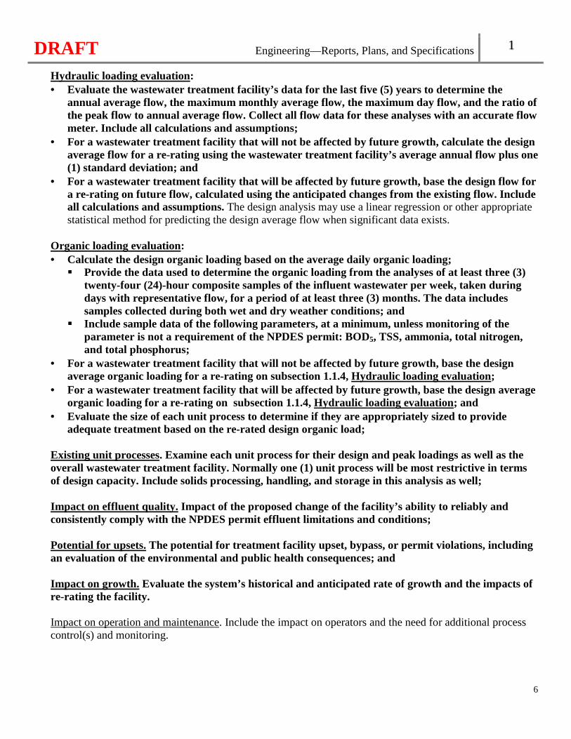
Hydraulic loading evaluation: • Evaluate the wastewater treatment facility’s data for the last five (5) years to determine the
annual average flow, the maximum monthly average flow, the maximum day flow, and the ratio of the peak flow to annual average flow. Collect all flow data for these analyses with an accurate flow meter. Include all calculations and assumptions;
• For a wastewater treatment facility that will not be affected by future growth, calculate the design average flow for a re-rating using the wastewater treatment facility’s average annual flow plus one (1) standard deviation; and
• For a wastewater treatment facility that will be affected by future growth, base the design flow for a re-rating on future flow, calculated using the anticipated changes from the existing flow. Include all calculations and assumptions. The design analysis may use a linear regression or other appropriate statistical method for predicting the design average flow when significant data exists.
Organic loading evaluation: • Calculate the design organic loading based on the average daily organic loading;
� Provide the data used to determine the organic loading from the analyses of at least three (3) twenty-four (24)-hour composite samples of the influent wastewater per week, taken during days with representative flow, for a period of at least three (3) months. The data includes samples collected during both wet and dry weather conditions; and
� Include sample data of the following parameters, at a minimum, unless monitoring of the parameter is not a requirement of the NPDES permit: BOD5, TSS, ammonia, total nitrogen, and total phosphorus;
• For a wastewater treatment facility that will not be affected by future growth, base the design average organic loading for a re-rating on subsection 1.1.4, Hydraulic loading evaluation;
• For a wastewater treatment facility that will be affected by future growth, base the design average organic loading for a re-rating on subsection 1.1.4, Hydraulic loading evaluation; and
• Evaluate the size of each unit process to determine if they are appropriately sized to provide adequate treatment based on the re-rated design organic load;
Existing unit processes. Examine each unit process for their design and peak loadings as well as the overall wastewater treatment facility. Normally one (1) unit process will be most restrictive in terms of design capacity. Include solids processing, handling, and storage in this analysis as well;
Impact on effluent quality. Impact of the proposed change of the facility’s ability to reliably and consistently comply with the NPDES permit effluent limitations and conditions;
Potential for upsets. The potential for treatment facility upset, bypass, or permit violations, including an evaluation of the environmental and public health consequences; and
Impact on growth. Evaluate the system’s historical and anticipated rate of growth and the impacts of re-rating the facility.
Impact on operation and maintenance. Include the impact on operators and the need for additional process control(s) and monitoring.
DRAFT Engineering—Reports, Plans, and Specifications 1
7
1.2 Engineering Report Engineering reports shall include the following in the subsections below, at a minimum [See 10 CSR 20-8.110(4)]. 1.2.1 Cover Page Include a statement identifying the owner and continuing authority (refer to 10 CSR 20-6.010(3)(B)), a contact person for each (including phone number and address), and signed, sealed, and dated by a Missouri registered professional engineer [See 10 CSR 20-8.110(4)(A)]. 1.2.2 Problem Defined Include a description of the existing system and an evaluation of the conditions and problems needing correction [See 10 CSR 20-8.110(4)(B)]. 1.2.3 Hydraulic and Organic Loads Establish the anticipated design average and design peak flows and organic loads for the existing and ultimate conditions. Include the basis of the projection reflect the existing or initial service area, and the anticipated future service area. More detail on flow and organic load information and data needed for new collection systems are included in section 1.1 [See 10 CSR 20-8.110(4)(C)]. 1.2.4 Impact on Existing Wastewater Facilities Evaluate the impact of the proposed project on downstream existing wastewater systems (including gravity sewers, alternative sewers, pumping stations, force mains, and treatment facilities) [See 10 CSR 20-8.110(4)(D)]. 1.2.5 Project Description Provide a written description of the project [See 10 CSR 20-8.110(4)(E)]. 1.2.6 Location Drawings Provide drawings identifying the site of the project and anticipated location and alignment of proposed facilities [See 10 CSR 20-8.110(4)(F)]. 1.2.7 Engineering Criteria Include engineering criteria to be used in design of the project [See 10 CSR 20-8.110(4)(G)].
DRAFT Engineering—Reports, Plans, and Specifications 1
8
1.2.8 Site Information Provide project site information, where applicable, including topography, soils, geologic conditions, depth to bedrock, groundwater level, floodway or floodplain considerations, distance to water supply structures, roads, residences, and other pertinent site information [See 10 CSR 20-8.110(4)(H)].
1.2.9 Alternative Selection Discuss the reasons for selection of the proposed alternative, including any pumping station sites, feasibility, and how the project fits into a long term plan [See 10 CSR 20-8.110(4)(I)].
1.3 Facility Plan Facility plans shall include the following in the subsections below, at a minimum, in addition to section 1.2 [See 10 CSR 20-8.110(5)]. 1.3.1 Planning and Service Area Include a description or drawings of the planning area, existing and potential future service areas, the site of the project, and anticipated location of the proposed facilities [See 10 CSR 20-8.110(5)(A)]. 1.3.2 Population Projection and Planning Period Base the present and predicted population on a twenty (20)-year planning period. Consider phased construction of wastewater facilities in rapid growth areas. Design sewers and other facilities with a design life in excess of twenty (20) years for the extended period [See 10 CSR 20-8.110(5)(B)]. 1.3.3 Wastewater Treatment Facility Design Capacity The wastewater treatment facility design capacity is the design average flow at the design average BOD5. Establish the anticipated design average and design peak flows and waste loads for the existing and ultimate planning period. Include the basis of the projection of initial and future flows and waste loads. Refer to section 1.1 [See 10 CSR 20-8.110(5)(C)]. 1.3.4 Initial Alternative Development Discuss the process of selection of wastewater treatment alternatives for detailed evaluation. Include all wastewater management alternatives considered, including no action, and the basis for the engineering judgement for selection of the alternatives chosen for detailed evaluation [See 10 CSR 20-8.110(5)(D)]. 1.3.5 Detailed Alternative Evaluation Include the following for the alternatives to be evaluated in detail [See 10 CSR 20-8.110(5)(E)]:
DRAFT Engineering—Reports, Plans, and Specifications 1
9
• Collection system revisions. Evaluate the proposed revisions to the existing collection system including adequacy of portions not being changed by the project;
• Wet weather flows. Provide facilities to transport and treat wet weather flows in a manner that complies with federal, state, and local regulations;
• Evaluate the no-discharge option and include it as an alternative in the facility plan. Also refer to 10 CSR 20-6.010(4)(D)1.;
• Evaluate the regionalization option and include it as an alternative in the facility plan; • Include the information outlined in section 11.3 when the project includes wastewater irrigation or
subsurface soil dispersal; • Site Evaluation. Consider the following criteria during site evaluation. Take appropriate measures
to minimize adverse impacts when a site is critical with respect to the following items: � Consider compatibility of the treatment process with the present and planned future land use,
including noise, potential odors, air quality, and anticipated solids processing and disposal techniques. Refer to Chapter 5, Minimum Separation Distances for minimum separation distances. Non-aerated lagoons should not be used if excessive sulfate is present in the wastewater. Wastewater treatment facilities should be separate from habitation or any area likely to be built up within a reasonable future period;
� Identify zoning and other land use restrictions; � Evaluate the accessibility and topography of the site; � Identify areas for future facility expansion; � Identify the direction of prevailing wind; � For flood protection, refer to Chapter 5, Flood Protection; � Include geologic information, depth to bedrock, karst features, or other geologic
considerations of significance to the project; � A geohydrologic evaluation conducted by the Department’s Missouri Geological Survey is
required in the following instances [See 10 CSR 20-8.110(5)(E)6.G.]: o All new wastewater treatment facilities to identify stream determinations (gaining or
losing);o All new outfalls or relocated outfalls; o All new or modified earthen basin structures. Earthen basin structures shall not be located
in areas receiving a severe collapse potential rating [See 10 CSR 20-8.110(5)(E)6.G.(III)]. Earthen basin structures located in areas receiving a severe overall geologic limitation rating are reviewed on a case-by-case basis. Earthen basin structures located in areas receiving a moderate collapse potential rating with an appropriate engineering solution are reviewed on a case-by-case basis; and
o All new features (e.g. wastewater irrigation sites, subsurface soil dispersal sites, etc.); � Protection of groundwater including public and private wells shall be provided [See 10 CSR
20-8.110(5)(E)6.H.]. When the proposed wastewater facilities will be near a water source or other drinking water facility, as determined by the Missouri Geological Survey or by the Department’s Public Drinking Water Branch, include an evaluation addressing the allowable distance between these wastewater facilities and the water source. Refer to Chapter 4, Potable Water Sources and Chapter 5, Minimum Separation Distances;
� Determine the soil type and suitability for construction and depth to normal and seasonal high groundwater;
� Submit a soil morphology analysis conducted by a qualified soil scientist for all subsurface soil dispersal systems. Refer to section 1.5;
DRAFT Engineering—Reports, Plans, and Specifications 1
10
� Identify the location, depth, and discharge point of any field tile or curtain drain in the immediate area of the proposed site;
� Include the present and known future effluent quality and monitoring requirements; � Provide a discussion of receiving waterbody access for the outfall line; and � Include a preliminary assessment of site availability;
• Engineering criteria. Provide the engineering criteria and assumptions used in the design of the project. Provide the basis for unit operation and preliminary unit process sizing. Refer to subsection 1.3.8 for additional information;
• Location Drawings. Provide drawings identifying the site of the project and anticipated location and alignment of proposed facilities;
• Flow diagram. Provide a preliminary flow diagram of treatment facility alternatives including all recycle flows;
• Flexibility. Assure compliance with requirements of arrangement of units and flexibility per subsections 5.2.6 through 5.2.7;
• Removal efficiencies. Provide estimated loadings to and removal efficiencies through each unit operation in addition to total removal efficiency and effluent quality (both concentrations and mass);
• Emergency operation. Provide a discussion of emergency operation measures as outlined in section 4.6 and subsection 5.5.1;
• New and innovative technology. See section 1.4. Provide a contingency plan, in the event that such new technology fails to meet the expected performance;
• Nutrient removal. Provide a discussion of nutrient removal capabilities including footprint available for expansion or treatment facility modifications necessary for nutrient removal for each alternative;
• Solids. Include the solids handling and disposal alternatives considered and method selected. Assure compliance with requirements of Chapter 8 and any conditions in the NPDES permit. This is critical to completion of a successful project;
• Treatment during construction. Develop a plan for the method and level of treatment (including solids processing, storage, and disposal) to be achieved during construction and include it in the facility plan. Refer to subsections 1.7.1 and 1.8.3;
• Operation and maintenance. Identify portions of the project which involve complex operation or maintenance requirements including laboratory requirements for operation, industrial sampling, and self-monitoring;
• Cost estimates. Present cost estimates for capital construction cost, annual operation and maintenance cost (including basis), and a twenty (20)-year present worth cost for each alternative;
• Environmental review. Include any additional environmental information meeting the criteria in 10 CSR 20-4.050, for projects receiving funding through the state grant and loan programs. Give consideration to minimizing any potential adverse environmental effects of the proposed project. Provide documentation of compliance with planning requirements of federal, state, and local agencies; and
• Water quality reports. Submit all reviews, studies, or reports in accordance with 10 CSR 20-7, Water Quality.
DRAFT Engineering—Reports, Plans, and Specifications 1
11
1.3.6 Final Project Selection Present the selected project from the alternatives considered under subsection 1.3.5, including the financing considerations and recommendations for implementation of the plan. Provide a project implementation schedule identifying project milestones [See 10 CSR 20-8.110(5)(F)]. 1.3.7 Appendices Technical Information and Design Criteria Due to the complexity of wastewater facilities or funding issues, include the following information upon the request of the Department. All system design information for all review purposes will be considered preliminary design data.
• Process facilities. Criteria selection and basis; hydraulic and organic loadings—minimum, average, maximum, and effect (wastewater and sludge processes); unit dimensions; rates and velocities; detentions concentrations; recycle; chemical additive control; physical control and flow metering; removals; effluent concentrations, etc. (include a separate tabulation for each unit to handle solid and liquid fractions); energy requirement; and flexibility.
• Process diagrams. Process configuration, interconnecting piping, processing, flexibility; hydraulic profile; organic loading profile; solids profile; solids control system; and flow diagram with capacities, etc.
• Laboratory. Physical and chemical tests and frequency to control process; time for testing; space and equipment requirements; and personnel requirements, and a brief description of the laboratory facility. See section 5.8.
• Operation and maintenance. Routine special maintenance duties; time requirements; tools, spare parts, equipment, vehicles, safety; maintenance workspace and storage; and personnel requirements.
• Chemical control. Processes needing chemical addition; chemicals and feed equipment; and tabulation of amounts, units, and total costs.
• Collection systems control. Cleaning and maintenance; regulator and overflow inspection and repair; flow gauging; industrial sampling and surveillance; ordinance enforcement; equipment requirements; trouble-call investigation; and personnel requirements.
• Control summary. Personnel; equipment; chemicals, utilities, list power requirements of major units; and summation.
1.4 New and Innovative Technology The policy of the Department is to encourage rather than obstruct the development of any new methods or equipment for treatment of wastewater. The lack of inclusion in the Missouri Wastewater Design Guides, of some types of wastewater treatment processes or equipment should not be construed as precluding their use. 1.4.1 Evaluation of Technology Performance The Department may approve new technologies of wastewater treatment processes and equipment under the condition that the operational reliability and effectiveness of the process or device has been demonstrated with a suitably-sized prototype unit operating at its design load conditions. To determine new technologies of wastewater treatment processes and equipment or applications have a reasonable and substantial chance of success, the facility plan requesting Department approval shall include the following, at a minimum
DRAFT Engineering—Reports, Plans, and Specifications 1
12
[See 10 CSR 8.110(6)(A)]: • Monitoring observations, including test results and engineering evaluations demonstrating the
efficiency of processes or equipment; • Detailed description of the sampling protocol and test methods which are sufficiently sensitive
analytical methods for detecting, identifying, and measuring the concentrations of pollutants; • Testing, including appropriately-composited samples, under various ranges of strength and flow
rates (including diurnal variations) and waste temperatures over a sufficient length of time to demonstrate expected performance under the range of climatic and other conditions which may be encountered in the area of the proposed installations. A control group may be needed to demonstrate effectiveness;
• Description of manufacturer’s warranty and performance warranty including all exclusions or limitations on the warranty, when available;
• Complete design requirements, calculations, and all assumptions clearly documented and explained;
• Documentation of how the new process or equipment functions; • A discussion of actual, full-scale operating experience or pilot test work. For full-scale operating
experience, include the length of time that each installation has been in operation. For pilot test work, include a copy of the associated pilot test plan and final pilot test results report;
• Discussion of known or anticipated start-up issues and operational issues that have occurred or may occur during the first year of operation;
• A description of specific operator knowledge and skills needed to operate the proposed technology including an estimate of increased operator attention needed during start-up and the first year of operation; and
• Other appropriate information. 1.4.2 Pilot Test or Demonstration Plan See 10 CSR 20-6.010(1)(B)8. for more pilot test information. Proposals for pilot tests and demonstration projects shall include the following, at a minimum, in addition to the facility plan information in section 1.3 [See 10 CSR 20-8.110(6)(B)]:
• Goals, objectives, and benefits with an explanation as to why a pilot study or demonstration project is needed to obtain additional engineering data;
• Literature identifying key design parameters and related experience; • A description of the proposal with schematic diagrams, pictures, drawings, or any other important
information; • Complete design requirements, calculations, and all assumptions clearly documented and
explained; • Identification of associated environmental impacts, both direct and indirect; • Detailed description of the sampling protocol and test methods which are sufficiently sensitive
analytical methods for detecting, identifying, and measuring the concentrations of pollutants; • Complete schedule for testing and evaluation including start, completion, and submittal of the
pilot test or demonstration results report; and • Other appropriate information.
DRAFT Engineering—Reports, Plans, and Specifications 1
13
1.4.3 Supervised Data The Department may require that appropriate testing be conducted and evaluations be made under the supervision of a competent process engineer other than those employed by the manufacturer, developer, or patent holder. All reports, proposals for testing including quality assurance/quality control, pilot test plans, and engineering evaluation of new processes or equipment shall be prepared, signed, sealed, and dated by a Missouri registered professional engineer [See 10 CSR 20-8.110(6)(C)]. 1.4.4 Evaluation of Collected Data All raw testing data and the evaluation of the data and performance shall be submitted for Department review upon conclusion of the project demonstration. The evaluation shall identify and justify the removal of any excursions not representative of the new technology process or equipment from the data evaluation [See 10 CSR 20-8.110(6)(D)]. The Department will evaluate the applicant provided data and compare it to the applicable effluent limitations and water quality standards to determine the consistency of the new technology or equipment’s performance.
1.5 Soils Report 10 CSR 20-6.010(4)(D)6. outlines when a soils report is applicable [See 10 CSR 20-8.110(7)]. 1.5.1 Soils All soils investigation and resulting reports shall be performed, signed, and dated by a qualified soil scientist as defined by section 701.040.1.(2)(e), RSMo 2016. Soil observation pits (backhoe or hand dug) excavated to a depth to reveal the major soil horizons shall be utilized [See 10 CSR 20-8.110(7)(A)].
1.5.2 Soils Investigation The Soil Survey Manual by Soil Science Division Staff, United States Department of Agriculture Handbook No. 18, as published March 2017, and/or the Field Book for Describing and Sampling Soils Version 3.0, should be used as a reference when investigating the soil treatment area(s). The number of soil observation pits should be sufficient to adequately represent the soils and landscapes of the proposed soil treatment area(s). The soil observation pits may be supplemented by soil borings to help determine the extent of similar soil properties. Each soil profile description should include the following: describers name; date described; slope— aspect, gradient, shape and position; horizon— nomenclature, depth (i.e., thickness), boundary, and matrix color; mottling— quantity, orientation and size; redoximorphic features— kind, quantity, and size; texture— percentage clay and sand (as applicable); structure— type, size and grade, and consistence; rock fragment— size and percentage; water table— depth and kind; drainage class; flooding— frequency and duration; ponding— frequency, depth, and duration; vegetative cover; and other pertinent features related to the treatment and control of the effluent within the soil.
DRAFT Engineering—Reports, Plans, and Specifications 1
14
1.5.3 Soils Report The soils report resulting from the investigation shall include the following information, at a minimum [See 10 CSR 8.110(7)(B)]:
• A copy of each soil profile description as described in subsection 1.5.2; • Description of all drainage features, rock outcrops, erosion and other natural features that may
influence the soil treatment area; • Identify any limiting conditions; • Provide documentation of any geologic risk factors affecting the soil’s ability to treat and disperse
effluent including dense tills, clay pans, fragipans, etc; • Provide a scaled site drawing or include sufficient dimensions to identify all applicable site
features that could impact the soil treatment area(s). Previously prepared or otherwise available drawings such as a survey prepared by a Missouri registered professional surveyor, an aerial photograph or digital orthophotograph prepared from a geographical information system, or other similar drawing may be used. The drawing should include the following, at a minimum: � The location of all soil observation pits with the extent of different soils clearly delineated; � Any existing or proposed dwellings and structures; � Any site disturbances such as excavated or fill areas, existing roadways, and other hardscapes
and proposed hardscapes or related site disturbances; � Location of all public and private wells, abandoned wells, or geothermal systems, and surface
water features that could either influence or be impacted by the proposed soil treatment area. Refer to Chapter 5 for minimum separation distances;
� North orientation arrow; � Identification of areas with conditions that would prohibit, limit or adversely impact the siting
of a soil treatment area including, but not limited to: sinkholes, wetland vegetation, bedrock outcrops, areas with a slope greater than fifteen percent (15%), and existing or abandoned field or drainage tiles; and
� Identification of known, proposed, and observed easements and right-of-ways; • A copy of the United States Geological Survey topographic map with the proposed soil treatment
area clearly delineated;• A copy of the United States Department of Agriculture Natural Resources Conservation Services
county soil survey map with the proposed soil treatment area clearly delineated; and • Conclusion. Provide a discussion of the findings and conclusions including the following, at a
minimum: � Available area for the soil treatment area; � Depth to limiting layers (e.g., water table, fragipan, bedrock, etc.); � Proposed application (loading) rates should take into consideration the drainage and
permeability of the soils and the distance to the limiting layer. Cite the source of the application rates for each soil horizon within the specific soil description;
� Flooding and ponding frequency; � Any relevant characteristics (e.g., bedrock outcrops, sinkholes or karst features, etc.) on the
specific site or in the surrounding area that may indicate vulnerability for surface water and groundwater contamination;
� Factors affecting the soils ability to treat and hydrologically control effluent; and � Citation of all documentation used during the investigation and soils report preparation that
led to the findings and conclusions.
DRAFT Engineering—Reports, Plans, and Specifications 1
15
1.5.4 Imported Soils When a facility is importing soils for the subsurface soil dispersal systems, the following shall be specified, at a minimum [See 10 CSR 8.110(7)(C)]:
• Imported soils possessing physical characteristics that are uniform in texture, structure, and pore space. Ensure uniformity and consistency of the physical characteristics as close as possible to the original state after transport;
• A sandy to loamy material, with less than ten percent (10%) clay and less than fifteen percent (15%) organic debris present;
• Prior to placing any imported soil, ensure an organic layer is not created by removal of plant residue and roots from the site;
• To prevent the formation of a platy structure— � Do not compact imported soil; � Use of a track type vehicle is encouraged. Where track type vehicles are not available, equipment
using high flotation tires should be used. These tires apply the vehicle’s weight across a large footprint for less compaction;
� Place imported soil in small “lift” increments of four to six inches (4" – 6") instead of one (1) thick layer; and
� Vertical separation for the subsurface soil dispersal site should consist of native soil with the fill being the cap with imported soils; and
• Imported soils should be allowed to settle for several days prior to installation of the subsurface soil dispersal system.
1.6 Summary of Design A summary of design shall be prepared, signed, sealed, and dated by a Missouri registered professional engineer, accompany the plans and specifications, and include the following in the subsections below, at a minimum [See 10 CSR 20-8.110(8)]. 1.6.1 Hydraulic and Organic Loading Provide flow and waste projections including design and peak hydraulic and organic loadings for sewers, pump stations, and wastewater treatment facilities. Include information to verify adequate downstream capacity of sewers, pump stations, and wastewater treatment and solids handling unit(s) [See 10 CSR 20-8.110(8)(A)]. 1.6.2 Process Units Type and size of individual process units including the following: unit dimensions; rates and velocities; detention times; concentrations; recycle; chemical additive control; physical control, flexibility, and flow metering [See 10 CSR 20-8.110(8)(B)].
DRAFT Engineering—Reports, Plans, and Specifications 1
16
1.6.3 Process Diagrams Show process diagrams, including flow diagrams with hydraulic and organic capacities [See 10 CSR 20-8.110(8)(C)]. 1.6.4 Removal Efficiencies Expected removal rates and concentrations of permitted effluent parameters in the discharge from the wastewater treatment facility, including a separate tabulation for each unit to handle solid and liquid fractions [See 10 CSR 20-8.110(8)(D)]. 1.6.5 Design Calculations Design calculations, tabulations, and assumptions clearly documented and explained from Chapters 2 through 12 used in the design of each unit process and the system(s) as a whole [See 10 CSR 20-8.110(8)(E)]. 1.6.6 Pump Curves Include the appropriate pump curve with the system curve superimposed, as applicable [See 10 CSR 20-8.110(8)(F)]. 1.6.7 Unusual Construction Include unusual specifications, construction materials, and construction methods; maps, photographs, diagrams; and other support data needed to describe the system [See 10 CSR 20-8.110(8)(G)]. 1.6.8 Exempt Design Calculations Unless stated in Chapters 2 through 12, specific design calculations for the architectural, structural, and mechanical components of a system do not have to be included with the design criteria [See 10 CSR 20-8.110(8)(H)]. 1.6.9 Anticipated Effluent Quality Provide the anticipated effluent quality [See 10 CSR 20-8.110(8)(I)]. The anticipated effluent quality may be determined by the operating permit, a total maximum daily load, or an antidegradation review.
1.7 Plans 1.7.1 General Plans shall contain the following, at a minimum [See 10 CSR 8.110(9)(A)]:
• Plan title. Include the following for all plans for wastewater facilities:
DRAFT Engineering—Reports, Plans, and Specifications 1
17
� Bear a suitable title showing the name of the owner and continuing authority (refer to 10 CSR 20-6.010(3)(B));
� Show the scale in feet; � Provide a graphical scale; � Indicate the north point; � Signed, sealed, and dated by a Missouri registered professional engineer each sheet; � Bear an appropriate title block according to 20 CSR 2030-2.050; and � Number each sheet;
• Plan format. Provide a plan that is— � Clear and legible (suitable for scanning); � Drawn to a scale that will permit all necessary information to be plainly shown; � Indicates the datum used; � Depicts locations and logs of test borings, where applicable. Include test boring logs on the
plans or in the specifications as an appendix; and � Blueprints and hand drafted plans are not acceptable;
• Plan contents. Detail plans consist of— � Plan views, elevations, sections, and supplementary views which, together with the
specifications and general layouts, provide the working information for the contract and construction of the facilities;
� Dimensions and relative elevations of structures, the location and outline form of equipment, location and size of piping, water levels, and ground elevations; and
� All known existing structures and utilities, both above and below ground, which might interfere with the proposed construction or require isolation setback, particularly water mains and water supply structures (i.e., wells, clear wells, basins, etc.), gas mains, storm drains, and telephone, cable, and power conduits. The location of all existing and proposed water supply structures located within five hundred feet (500') of the proposed or existing wastewater treatment facility should be shown;
• Hydraulic profile. Include a hydraulic profile for all wastewater treatment facilities; and • Operation during construction. Specify the procedure for operation during construction that
complies with the plan outlined in subsections 1.3.5. and 1.8.3. 1.7.2 Plans of Sewers General plan. This plan shall show the following [See 10 CSR 20-8.110(9)(B)1.]:
• Geographical features. � Topography and elevations. Clearly show existing or proposed streets and all streams or water
surfaces. Contour lines at suitable intervals should be included; � Streams. Depict the direction of flow in all streams and high and low water elevations of all
water surfaces; and � Boundaries. Depict the boundary lines of the continuing authority and the area to be sewered;
and • Sewers. Show the location, size, and direction of flow of relevant existing and proposed sanitary
and combined sewers draining to the treatment facility concerned. Detail plans. Detail plans shall be submitted with [See 10 CSR 8.110(9)(B)2.]:
DRAFT Engineering—Reports, Plans, and Specifications 1
18
• Profiles having a horizontal scale of not more than one hundred feet (100') to the inch and a vertical scale of not more than ten feet (10') to the inch. Plan views should be drawn to a corresponding horizontal scale and shown on the same sheet;
• Location of streets and sewers; • Line of ground surface; pipe size, material, and type; length between manholes; invert and surface
elevation at each manhole; grade of sewer between each two (2) adjacent manholes; and any special construction features. Number all manholes on the plan and correspondingly number them on the profile;
• Where there is any question of the sewer being sufficiently deep to serve any residence, plot the elevation and location of the basement floor on the profile of the sewer which is to serve the residence in question;
• Locations of all special features such as inverted siphons, concrete encasements, elevated sewers, etc.; and
• Furnish detail drawings to show the following particulars: � All stream crossings with elevations of the stream bed and ordinary high water mark, normal,
and low water levels; � Details of all special sewer joints and cross-sections; and � Details of all sewer appurtenances such as manholes, inspection chambers, inverted siphons,
regulators, tide gates, and elevated sewers. 1.7.3 Plans of Wastewater Pumping Stations Location plan. This plan shall show the following [See 10 CSR 8.110(9)(C)1.]:
• The location and extent of the tributary area; • Any continuing authority boundaries with the tribut ary area; and • The location of the pumping station and force main and pertinent elevations.
Detail plans. Detail plans shall show the following, where applicable [See 10 CSR 8.110(9)(C)2.]:
• Topography of the site; • Existing pumping station; • Proposed pumping station, including provisions for installation of future pumps; • Maximum elevation of wastewater in the collection system upon occasion of power failure; • Maximum hydraulic gradient in downstream gravity sewers when all installed pumps are in
operation; • Test boring and groundwater elevations; • All pumping station appurtenances such as pumps, valves, level control switches, hatches, safety
equipment, ventilation equipment, and hoisting equipment; and • The one hundred (100)-year flood elevations or highest historical flood of record elevation and
their boundaries. Refer to Chapter 5, Flood Protection. 1.7.4 Plans of Wastewater Treatment Facilities Location plan.
• A location plan shall show the wastewater treatment facility in relation to the remainder of the system [See 10 CSR 8.110(9)(D)1.A.].
DRAFT Engineering—Reports, Plans, and Specifications 1
19
• Sufficient topographic features shall be included to indicate its location with relation to streams and the point of discharge of treated effluent [See 10 CSR 8.110(9)(D)1.B.].
General layout. Layouts of the proposed wastewater treatment facility shall show [See 10 CSR 8.110(9)(D)2.]—
• Topography of the site; • Size and location of treatment facility structures; • Schematic flow diagram(s) showing the flow through various units and showing utility systems
serving the facility processes; • Piping, including any arrangement for unit isolation (identify materials handled and direction of
flow through pipes, including arrangements for independent operation); • Hydraulic profiles showing the flow of wastewater, supernatant liquor, recycle streams, and
solids; and • Test borings and groundwater elevations.
Detail plans. Detail plans shall show the following, where applicable [See 10 CSR 8.110(9)(D)3.]:
• Location, dimensions, and elevations of all existing and proposed treatment facilities and solids handling facilities;
• Elevations of high and low water level of the body of water to which the facility effluent is to be discharged;
• Type, size, pertinent features, and operating capacity of all pumps, blowers, motors, and other mechanical devices;
• Minimum, design average, and peak hourly hydraulic flow in hydraulic profile with wastewater, supernatant liquor, and solids flow through the treatment facility;
• Existing and proposed solids storage volumes in plan and profile; • Adequate description of any features not otherwise covered by the specifications or facility plan;
and • The one hundred (100)-year flood elevations or highest historical flood of record elevation and
their boundaries. Refer to Chapter 3, Flood Protection.
1.8 Specifications 1.8.1 Cover Page Specification shall be prepared, signed, sealed, and dated by a Missouri registered professional engineer for the construction of sewers, pumping stations, wastewater treatment facilities, and all other appurtenances, and accompany the plans. The initial page shall bear the owner and continuing authority name, a contact person for each (including phone number and address) [See 10 CSR 8.110(10)(A)]. 1.8.2 Technical Specifications The technical specifications accompanying construction drawings shall include the following, but not be limited to all construction information not shown on the drawings which is necessary to inform the
DRAFT Engineering—Reports, Plans, and Specifications 1
20
builder, in detail, of the design requirements for the quality of materials, workmanship, and fabrication of the project[See 10 CSR 8.110(10)(B)]:
• The type, size, strength, operating characteristics, and rating of equipment; • Allowable infiltration; • The complete requirements for all mechanical and electrical equipment (including machinery,
valves, piping, and jointing of pipe); • Electrical apparatus, wiring, instrumentation, and meters; • Laboratory fixtures and equipment; • Operating tools; • Construction materials; • Special filter materials (such as stone, sand, gravel, or slag); • Miscellaneous appurtenances; • Chemicals when used; • Instructions for testing materials and equipment as necessary to meet design standards; and • Performance tests for the completed facilities and component units. It is suggested that these
performance tests be conducted at design load conditions wherever practical. 1.8.3 Operation During Construction Specifications shall contain a program for keeping existing wastewater treatment facility units in operation during construction. Should it be necessary to take units out of operation, specifications shall include detailed construction requirements and schedules to maintain compliance with water quality standards and the facility’s NPDES permit. See subsections 1.3.5 and 1.7.1 [See 10 CSR 8.110(10)(C)].
1.9 Revisions to Approved Plans or Specifications 1.9.1 General Any revisions from approved plans or specifications affecting capacity, flow, system layout, operation of units, or point of discharge shall be approved by the Department in writing, before such changes are made [See 10 CSR 8.110(11)(A)]. Submit revised plans or specifications in advance of any construction work to allow time for review and approval for any changes that impact the permit. Revisions to structural components or minor changes not affecting capacity, flows, or operations will be permitted during construction without additional approvals. Major revisions to approved plans or specifications may require a new construction permit in accordance with 10 CSR 20-6.010(4). 1.9.2 Addendum Addenda shall be signed, sealed, and dated by a Missouri registered professional engineer [See 10 CSR 8.110(11)(B)].
DRAFT Engineering—Reports, Plans, and Specifications 1
21
1.9.3 Change Order Change orders shall be signed, sealed, and dated by a Missouri registered professional engineer. The owner, continuing authority, and contractor shall sign and date change orders as well [See 10 CSR 8.110(11)(C)]. 1.9.4 As-Built Plans As-built plans clearly showing the alterations shall be submitted upon Department request at the completion of the work [See 10 CSR 8.110(11)(D)].

DRAFT
22
DRAFT Gravity Sewers 2
Chapters 2: Gravity Sewers
23
2.1 Approval of Sewers Rain water from roofs, streets, and other areas and groundwater from foundation drains shall be excluded from sewers [See 10 CSR 20-8.120(2)].
2.2 Design Capacity and Design Flow 2.2.1 Sewer Capacity Design sewer capacities for the estimated ultimate tributary population, except when considering parts of the system that can be readily increased in capacity. Similarly, give consideration to the maximum anticipated capacity of institutions, industrial parks, etc. Evaluate the following factors when determining the capacities of sanitary sewers:
• Design peak hourly flow; • Additional maximum wastewater or waste flow from industrial plants; • Inflow and infiltration (I/I); • Topography of area; • Location of wastewater treatment facilities; • Depth of excavation; and • Pumping requirements.
2.2.2 Basis of Sewer Flows Base sewer flows on the design peak hourly flow in accordance with section 1.1 and design to prevent or eliminate sanitary sewer overflows (SSOs).
2.3 Details of Design and Construction 2.3.1 Minimum Size Gravity sewers conveying raw wastewater are at least eight inches (8") in diameter, except in circumstances where smaller diameter pipe can be justified. The minimum size of six-inch (6") diameter pipe for schools, resorts, subdivisions located in rural areas, and similar establishments will be considered based on engineering justification and approved by the Department on a case-by-case basis.
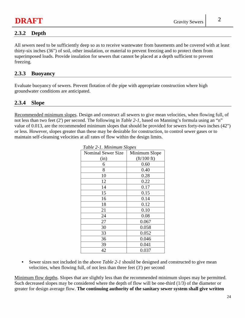
DRAFT Gravity Sewers 2
24
2.3.2 Depth All sewers need to be sufficiently deep so as to receive wastewater from basements and be covered with at least thirty-six inches (36") of soil, other insulation, or material to prevent freezing and to protect them from superimposed loads. Provide insulation for sewers that cannot be placed at a depth sufficient to prevent freezing. 2.3.3 Buoyancy Evaluate buoyancy of sewers. Prevent flotation of the pipe with appropriate construction where high groundwater conditions are anticipated. 2.3.4 Slope Recommended minimum slopes. Design and construct all sewers to give mean velocities, when flowing full, of not less than two feet (2') per second. The following in Table 2-1, based on Manning’s formula using an “n” value of 0.013, are the recommended minimum slopes that should be provided for sewers forty-two inches (42") or less. However, slopes greater than these may be desirable for construction, to control sewer gases or to maintain self-cleansing velocities at all rates of flow within the design limits.
Table 2-1. Minimum Slopes Nominal Sewer Size
(in) Minimum Slope
(ft/100 ft) 6 0.60 8 0.40 10 0.28 12 0.22 14 0.17 15 0.15 16 0.14 18 0.12 21 0.10 24 0.08 27 0.067 30 0.058 33 0.052 36 0.046 39 0.041 42 0.037
• Sewer sizes not included in the above Table 2-1 should be designed and constructed to give mean
velocities, when flowing full, of not less than three feet (3') per second Minimum flow depths. Slopes that are slightly less than the recommended minimum slopes may be permitted. Such decreased slopes may be considered where the depth of flow will be one-third (1/3) of the diameter or greater for design average flow. The continuing authority of the sanitary sewer system shall give written
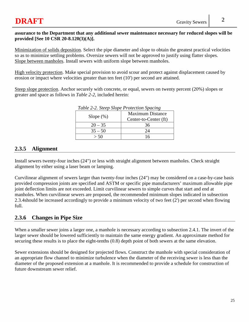
DRAFT Gravity Sewers 2
25
assurance to the Department that any additional sewer maintenance necessary for reduced slopes will be provided [See 10 CSR 20-8.120(3)(A)]. Minimization of solids deposition. Select the pipe diameter and slope to obtain the greatest practical velocities so as to minimize settling problems. Oversize sewers will not be approved to justify using flatter slopes. Slope between manholes. Install sewers with uniform slope between manholes. High velocity protection. Make special provision to avoid scour and protect against displacement caused by erosion or impact where velocities greater than ten feet (10') per second are attained. Steep slope protection. Anchor securely with concrete, or equal, sewers on twenty percent (20%) slopes or greater and space as follows in Table 2-2, included herein:
Table 2-2. Steep Slope Protection Spacing
Slope (%) Maximum Distance Center-to-Center (ft)
20 – 35 36 35 – 50 24
> 50 16 2.3.5 Alignment Install sewers twenty-four inches (24") or less with straight alignment between manholes. Check straight alignment by either using a laser beam or lamping. Curvilinear alignment of sewers larger than twenty-four inches (24") may be considered on a case-by-case basis provided compression joints are specified and ASTM or specific pipe manufacturers’ maximum allowable pipe joint deflection limits are not exceeded. Limit curvilinear sewers to simple curves that start and end at manholes. When curvilinear sewers are proposed, the recommended minimum slopes indicated in subsection 2.3.4should be increased accordingly to provide a minimum velocity of two feet (2') per second when flowing full. 2.3.6 Changes in Pipe Size When a smaller sewer joins a larger one, a manhole is necessary according to subsection 2.4.1. The invert of the larger sewer should be lowered sufficiently to maintain the same energy gradient. An approximate method for securing these results is to place the eight-tenths (0.8) depth point of both sewers at the same elevation. Sewer extensions should be designed for projected flows. Construct the manhole with special consideration of an appropriate flow channel to minimize turbulence when the diameter of the receiving sewer is less than the diameter of the proposed extension at a manhole. It is recommended to provide a schedule for construction of future downstream sewer relief.
DRAFT Gravity Sewers 2
26
2.3.7 Materials Any generally accepted material for sewers will be given consideration, but the material selected should be adapted to local conditions, such as character of industrial wastes, possibility of septicity, soil characteristics, exceptionally heavy external loadings, abrasion, corrosion, or similar problems. All sewer pipe and joint materials conform to the appropriate ASTM specifications. Use suitable couplings complying with ASTM specifications for joining dissimilar materials. Joint leakage limitations are outlined in subsection 2.3.9, Water (hydrostatic) test, or subsection 2.3.9, Air test. Design all sewers to prevent damage from superimposed live, dead, and frost-induced loads. Make proper allowance for loads on the sewer because of soil and potential groundwater conditions, as well as the width and depth of the trench. Where necessary, use special bedding, haunching, initial backfill, concrete cradle, or other special construction to withstand anticipated superimposed loading or loss of trench wall stability. Refer to subsection 2.3.8, Bedding, haunching, and initial backfill for appropriate ASTMs. For new pipe or joint materials for which ASTM standards have not been established, provide complete material and installation specifications developed on the basis of criteria adequately documented and certified in writing by the manufacturer to be satisfactory for the specific detailed plans for approval by the Department. 2.3.8 Installation Standards. Specify appropriate installation requirements based on the criteria, standards, and requirements established by industry in its technical publications. Specify pipe installation and methods of bedding and backfilling so as not to damage the pipe or its joints, impede cleaning operations, and future tapping, create excessive side fill pressures and ovalation of the pipe, nor seriously impair flow capacity. Trenching.
• Provide sufficient trench width to allow the pipe to be laid and jointed properly and to allow the bedding and haunching to be placed and compacted to adequately support the pipe. Keep the trench sides as nearly vertical as possible. Use appropriate bedding class and pipe strength when wider trenches are specified.
• Evaluate the size and stiffness of the pipe, stiffness of the embedment, and insitu soil and depth of cover in determining the minimum trench width necessary to adequately support the pipe in unsupported and unstable soil.
• Remove ledge rock, boulders, and large stones to provide a minimum clearance of four inches (4") below and on each side of all pipe(s).
• Dewatering. Remove all water entering the excavations or other parts of the work until all the work has been completed. Sanitary sewers that ultimately arrive at existing pumping stations or wastewater treatment facilities cannot be used for the disposal of trench water.
Bedding, haunching, and initial backfill.
• Ductile iron pipe. Embedment materials for bedding and initial backfill, as described in ASTM A746 – 09(2014) Standard Specification for Ductile Iron Gravity Sewer Pipe, as approved and published October 1, 2014, for Type 1 through Type 5 laying conditions, shall be used for ductile
DRAFT Gravity Sewers 2
27
iron pipe provided the proper strength pipe is used with the specified bedding to support the anticipated load based on the type of soil encountered and potential groundwater conditions [See 10 CSR 20-8.120(3)(B)1.]. This standard is incorporated by reference in this rule, as published by ASTM International, 100 Barr Harbor Drive, P.O. Box C700, West Conshohocken, PA 19428-2959. This rule does not incorporate any subsequent amendments or additions.
• Plastic pipe. Embedment materials for bedding, haunching, and initial backfill, Classes I, II, or III, as described in ASTM D2321 – 14e1 Standard Practice for Underground Installation of Thermoplastic Pipe for Sewers and Other Gravity-Flow Applications, as approved and published August 1, 2014, shall be used provided the proper strength pipe is used with the specified bedding to support the anticipated load, based on the type of soil encountered and potential groundwater conditions [See 10 CSR 20-8.120(4)(B)1.B.]. This standard is incorporated by reference in this rule, as published by ASTM International, 100 Barr Harbor Drive, P.O. Box C700, West Conshohocken, PA 19428-2959. This rule does not incorporate any subsequent amendments or additions.
• Composite pipe. Except as described in ASTM D2680 – 01(2014) Standard Specification for Acrylonitrile-Butadiene-Styrene (ABS) and Poly(Vinyl Chloride) (PVC) Composite Sewer Piping, as approved and published August 1, 2014, the bedding, haunching, and initial backfill requirements for composite pipe shall be the same as for plastic pipe [See 10 CSR 20-8.120(3)(B)3.]. This standard is incorporated by reference in this rule, as published by ASTM International, 100 Barr Harbor Drive, P.O. Box C700, West Conshohocken, PA 19428-2959. This rule does not incorporate any subsequent amendments or additions.
Final backfill.
• Final backfill should be of a suitable material removed from excavation except where other material is specified. Debris, frozen material, large clods, stones, organic matter, or other unstable materials cannot be used for final backfill within two feet (2') of the top of the pipe.
• Place final backfill in such a manner so as not to disturb the alignment of the pipe. Deflection test.
• Perform deflection tests on all flexible pipe. Conduct the test after the final backfill has been in place at least thirty (30) days to permit stabilization of the soil-pipe system.
• No pipe shall exceed a deflection of five percent (5%) of the inside diameter [See 10 CSR 20-8.120(3)(C)].
• The diameter of the rigid ball or mandrel used for the deflection test is not less than ninety-five percent (95%) of the base inside diameter or average inside diameter of the pipe depending on which is specified in the ASTM specification, including the appendix, to which the pipe is manufactured.
• Perform the tests without mechanical pulling devices. • Use a mandrel having nine (9) or more odd number of flutes or points.
Video inspection. Video inspection of all new and rehabilitated sewers after installation is recommended. 2.3.9 Joints and Infiltration Joints. Include the installation of joints and the materials used in the specifications. Design sewer joints to minimize infiltration and to prevent the entrance of roots throughout the life of the system. Portland cement mortar joints are not acceptable.
DRAFT Gravity Sewers 2
28
Service connections. • Service connections to the sewer main shall be watertight and cannot protrude into the sewer [See
10 CSR 20-8.120(3)(D)1.]. • When a saddle-type connection is used, select a device designed to join with the types of pipe which are
to be connected. • Use compatible and corrosion resistant materials for service connections to sewer mains.
Leakage tests. Leakage tests shall be specified for gravity sewers except polyvinyl chloride (PVC) pipe with a diameter of twenty-seven inches (27") or less [See 10 CSR 20-8.120(4)(C)2.]. This may include appropriate water or low pressure air testing. Give consideration to the range in groundwater elevations during the testing and those anticipated during the design life of the sewer when specifying the leakage testing method(s).
• Water (hydrostatic) test. The leakage exfiltration or infiltration shall not exceed one hundred (100) gallons per inch of pipe diameter per mile per day for any section between manholes of the system. An exfiltration or infiltration test shall be performed with a minimum positive head of two feet (2'). The exfiltration or infiltration test shall, as a minimum, conform to the test procedure described in ASTM C969 – 17 Standard Practice for Infiltration and Exfiltration Acceptance Testing of Installed Precast Concrete Pipe Sewer Lines, as approved and published April 1, 2017, for precast concrete pipe [See 10 CSR 20-8.120(3)(D)2.A.]. This standard is incorporated by reference in this rule, as published by ASTM International, 100 Barr Harbor Drive, P.O. Box C700, West Conshohocken, PA 19428-2959. This rule does not incorporate any subsequent amendments or additions.
• Air test. The air test shall, as a minimum, conform to the test procedure described in ASTM C1103 – 14 Standard Practice for Joint Acceptance Testing of Installed Precast Concrete Pipe Sewer Lines, as approved and published November 1, 2014, for concrete pipe twenty-seven inches (27") or greater in diameter, and ASTM F1417 – 11a(2015) Standard Practice for Installation Acceptance of Plastic Non-pressure Sewer Lines Using Low-Pressure Air, as approved and published August 1, 2015, for plastic, composite, and ductile iron pipe [See 10 CSR 20-8.120(3)(D)2.B.]. These standards are incorporated by reference in this rule, as published by ASTM International, 100 Barr Harbor Drive, P.O. Box C700, West Conshohocken, PA 19428-2959. This rule does not incorporate any subsequent amendments or additions.
2.3.10 Bore or Tunnel The spacing of supports for carrier pipe through casings needs to maintain the grade, slope, and structural integrity of a pipe. Where casing pipe is utilized, include the following:
• Materials. Where casing pipe is utilized it shall be constructed of steel with welded joints conforming to AWWA C200-17 Steel Water Pipe, 6 In. (150 mm) and Larger, as approved and published August 1, 2017, or ductile iron pipe with mechanical joints [See 10 CSR 20-8.120(3)(E)]. This standard is incorporated by reference in this rule, as published by American Water Works Association (AWWA), 6666 West Quincy Avenue, Denver, CO 80235-3098. This rule does not incorporate any subsequent amendments or additions;
• Spacers. Provide spacers a minimum of three quarter inches (0.75") of clearance between the carrier pipe’s outside diameter and the casing pipe’s inside diameter. Install spacers a maximum of eight feet (8') apart along the length of the carrier pipe with one (1) casing spacing within two feet (2') of each side of a pipe joint;
DRAFT Gravity Sewers 2
29
• End Seals. Secure watertight seals to both ends of the casing and carrier pipe; and • Installation. Install the casing pipe by boring and simultaneously jacking the pipe into place. There
should be no annular space between the outside of the casing pipe and the undisturbed earth.
2.4 Manholes 2.4.1 Location Manholes shall be installed [See 10 CSR 20-8.120(4)(A)]—
• At the end of each line; • At all changes in grade, size, or alignment; and • At all sewer pipe intersections.
Install manholes—
• At distances not greater than four hundred feet (400') for sewers that are fifteen inches (15") or less; and • At distances not greater than five hundred feet (500') for sewers that are sixteen inches to thirty inches
(16"–30"). • Spacing of manholes greater than the distances above may be approved by the Department in cases
where the continuing authority of the sanitary sewer system gives written assurance to the Department that adequate cleaning equipment justifies such spacing.
Cleanouts may be used only for special conditions and are not expected to be substituted for manholes nor installed at the end of laterals greater than one hundred fifty feet (150') in length. Enclosed cleanouts in a watertight valve box with a locking cap. Provide cleanouts with proper support, such as crushed stone, concrete pads, or a well compacted trench bottom. Also see subsection 2.4.3, Cleanout. 2.4.2 Drop Type Provide a drop pipe for a sewer entering a manhole at an elevation of twenty-four inches (24") or more above the manhole invert. Where the difference in elevation between the incoming sewer and the manhole invert is less than twenty-four inches (24"), fillet the invert to prevent solids deposition. Drop manholes should be constructed with an outside drop connection. Secure inside drop connections (when necessary) to the interior wall of the manhole and provide access for cleaning. When using precast manholes, drop connections must not enter the manhole at a joint [See 10 CSR 20-8.120(4)(B)]. Due to the unequal earth pressures that would result from the backfilling operation in the vicinity of the manhole, the entire outside drop connection should be properly supported to anchor the connection to the manhole.
DRAFT Gravity Sewers 2
30
2.4.3 Diameter Manhole. The minimum diameter of manholes is forty-two inches (42") on eight-inch (8") diameter gravity sewer lines and forty-eight inches (48") on all sewer lines larger than eight inches (8") in diameter. Larger diameters are needed for manholes with large diameter sewers or multiple pipes connecting at the manhole in order to maintain structural integrity. Manhole frame and cover. Provide a minimum access diameter of twenty-two inches (22"). Cleanout. Cleanouts shall be a minimum of eight inches (8") in diameter [See 10 CSR 20-8.120(4)(C)]. 2.4.4 Flow Channel The flow channel straight through a manhole should be made to conform as closely as possible in shape and slope to that of the connecting sewers. The channel walls should be formed or shaped to the full height of the crown of the outlet sewer in such a manner as to not obstruct maintenance, inspection, or flow in the sewers. Changes in direction of flow should generally not exceed ninety degrees (90°). Construct a separate channel for each incoming sewer with the channels gradually merging together ahead of the outlet using uniform curves where a junction of two (2) or more sewers occurs. The invert of any trunk or interceptor sewer should be slightly lower than the invert of the sewer main to avoid slack-water areas where solids may accumulate. When curved flow channels are specified in manholes, including inlets, the minimum slopes indicated in subsection 2.3.4, Recommended minimum slopes should be increased to maintain acceptable velocities. 2.4.5 Bench Provide a bench on each side of any manhole channel when the pipe diameter(s) are less than the manhole diameter. The bench should be sloped no less than a one-half inch per foot (0.5 in/ft). No sewer, service connection, or drop manhole pipe shall discharge onto the surface of the bench [See 10 CSR 20-8.120(4)(D)]. 2.4.5 Watertightness Manholes shall be watertight and constructed of precast concrete or poured-in-place concrete type. Precast manholes shall conform to the design and test methods specified in ASTM C478 – 15a Standard Specification for Circular Precast Reinforced Concrete Manhole Sections, as approved and published October 1, 2015, and C497 – 17 Standard Test Methods for Concrete Pipe, Manhole Sections or Tile, as approved and published April 1, 2017 [See 10 CSR 20-8.120(4)(E)]. These standards are incorporated by
DRAFT Gravity Sewers 2
31
reference in this rule, as published by ASTM International, 100 Barr Harbor Drive, P.O. Box C700, West Conshohocken, PA 19428-2959. This rule does not incorporate any subsequent amendments or additions. Seal manhole lift holes, grade adjustment rings, precast section joints, and any additional areas potentially subject to infiltration watertight with non-shrinking mortar or other material approved by the Department. Join inlet and outlet pipes to the manhole with a gasketed flexible watertight connection or another watertight connection arrangement that allows differential settlement of the pipe and manhole wall to take place. Watertight manhole covers are to be used wherever the manhole tops may be flooded by street runoff or high water. Bolt-down cover assemblies may be needed on manholes subject to displacement by sewer surcharging. Locked manhole covers may be desirable in isolated easement locations or where vandalism may be a problem. 2.4.6 Inspection and Testing Vacuum testing, if specified for concrete sewer manholes, shall conform to the test procedures in ASTM C1244 – 11(2017) Standard Test Method for Concrete Sewer Manholes by the Negative Air Pressure (Vacuum) Test Prior to Backfill, as approved and published April 1, 2017, or the manufacturer’s recommendation [See 10 CSR 20-8.120(4)(F)1.]. This standard is incorporated by reference in this rule, as published by ASTM International, 100 Barr Harbor Drive, P.O. Box C700, West Conshohocken, PA 19428-2959. This rule does not incorporate any subsequent amendments or additions. Exfiltration testing, if specified for concrete sewer manholes, shall conform to the test procedures in ASTM C969 – 17 Standard Practice for Infiltration and Exfiltration Acceptance Testing of Installed Precast Concrete Pipe Sewer Lines, as approved and published April 1, 2017 [See 10 CSR 20-8.120(4)(F)2.]. This standard is incorporated by reference in this rule, as published by ASTM International, 100 Barr Harbor Drive, P.O. Box C700, West Conshohocken, PA 19428-2959. This rule does not incorporate any subsequent amendments or additions. 2.4.7 Corrosion Protection for Manholes Provide corrosion protection on the interior of the manholes where corrosive conditions due to septicity or other causes are anticipated. 2.4.8 Electrical Install electrical equipment used in manholes per subsection 4.1.3, Electrical equipment. 2.4.9 Buoyancy Evaluate buoyancy of manholes. Prevent flotation of the manhole with appropriate construction where high groundwater conditions are anticipated.
DRAFT Gravity Sewers 2
32
2.5 Inverted Siphons Inverted siphons are used to convey wastewater by gravity under depressions.
2.5.1 Design Design inverted siphons with at least two (2) barrels and a minimum pipe size of six inches (6"). Provide sufficient head and appropriate pipe sizes to secure velocities of at least three feet (3') per second for design average flows. Arrange the inlet and outlet details so that the design average flow is diverted to one (1) barrel and so that either barrel may be removed from service for cleaning. 2.5.2 Cleaning and Maintenance Provide the necessary appurtenances for maintenance, convenient flushing, and cleaning equipment. The inlet and discharge structures should have adequate clearances for cleaning equipment, inspection, and flushing. The vertical alignment should permit cleaning and maintenance. 2.5.3 Leakage Testing Test inverted siphons according to subsection 2.3.9, Leakage tests.
2.6 Sewers in Relation to Streams 2.6.1 Location of Sewers in Streams Cover depth. The top of all sewers entering or crossing streams should be at a sufficient depth below the natural bottom of the stream bed to protect the sewer line. Design to meet the following cover depth:
• At least one foot (1') of cover where the sewer is located in rock; • At least three feet (3') of cover in other stream bed material and in major streams; and • In paved stream channels, the top of the sewer line should be placed below the bottom of the channel
pavement. Horizontal location. Locate sewers along streams at least ten feet (10') horizontally from the ordinary high water mark of the stream to provide for future possible stream widening and to prevent pollution by siltation during construction and to minimize possible exposure due to erosion. Structures. Locate sewer outfalls, headwalls, manholes, gate boxes, or other structures so they do not interfere with the free discharge of flood flows of the stream. Alignment. Sewers crossing streams should be designed to cross the stream as nearly perpendicular to the stream flow as possible and free from change in grade. Stream crossings. Design sewer systems to minimize the number of stream crossings.
DRAFT Gravity Sewers 2
33
2.6.2 Construction Materials. Construct sewers entering or crossing streams of ductile iron pipe with mechanical joints. Use stone, coarse aggregate, washed gravel, or other materials which will not readily erode, cause siltation, damage the pipe during placement, or corrode the pipe to backfill the trench. Siltation and erosion. Employ construction methods that will minimize siltation and erosion. Specify the method(s) to be employed in the construction of sewers in or near streams. Provide adequate control of siltation and erosion by limiting unnecessary excavation, disturbing or uprooting trees and vegetation, dumping of soil or debris, or pumping silt-laden water into the stream. Specify clean-up, grading, seeding, planting, or restoration of all work areas to begin immediately. Protect exposed areas within seven (7) days. Alternative construction methods. When the alignment of a sewer crosses a stream, give consideration to trenchless construction technologies as an alternative to open trench construction in accordance with section 2.10.
2.7 Aerial Crossings 2.7.1 Support Provide support for all joints in pipes utilized for aerial crossings. Design the supports to prevent frost heave, overturning, and settlement. 2.7.2 Freezing Provide precautions against freezing, such as insulation and increased slope. Provide expansion jointing between above-ground and below-ground sewers. Use special construction techniques to minimize frost heaving where buried sewers change to aerial sewers. 2.7.3 Flooding Consider the impact of flood waters and debris for aerial stream crossings. The bottom of the pipe should be placed no lower than the elevation of the fifty (50)-year flood. 2.7.4 Materials Construct aerial crossings of ductile iron pipe with mechanical joints; otherwise, construct them so that they will remain watertight and free from changes in alignment or grade.
DRAFT Gravity Sewers 2
34
2.8 Protection of Water Supplies 2.8.1 Cross Connections There shall be no physical connections between a public or private potable water supply system and a sewer or appurtenance which would permit the passage of any wastewater or polluted water into the potable supply [See 10 CSR 20-8.120(5)(A)]. 2.8.2 Relation to Water Works Structures Sewers shall be laid at least fifty feet (50') horizontally from any existing or proposed public water supply well or other water supply sources or structures [See 10 CSR 20-8.120(10)(B)]. Refer to 10 CSR 23-3.010. Depict all existing water works units, such as basins, wells, or other treatment units, within two hundred feet (200') of the proposed sewer on the engineering plans.
2.8.3 Relation to Water Mains Horizontal and vertical separation.
• Install sewers at least ten feet (10') horizontally from any existing or proposed water main. Measure the distance from edge-to-edge. In cases where it is not practical to maintain a ten-foot (10') separation, install the water main is in a separate trench or on an undisturbed earth shelf located on one (1) side of the sewer and at an elevation so the bottom of the water main is at least eighteen inches (18") above the top of the sewer.
• When it is impossible to obtain proper horizontal and vertical separation the sewer must be constructed of slip-on or ductile iron mechanical joint pipe or continuously encased and be pressure rated to at least one hundred fifty pounds per square inch (150 psi) and pressure tested to ensure watertightness [See 10 CSR 20-8.120(5)(C)1.A.].
• Manholes shall be located at least ten feet (10') horizontally from any existing or proposed water main [See 10 CSR 20-8.120(5)(C)1.B.].
• When it is impossible to obtain proper horizontal separation as described above for manholes, the manhole shall be located at least ten feet (10') from a water main joint or centered on a twenty foot (20') length of water main pipe [See 10 CSR 20-8.120(5)(C)1.C.].
Crossings. � Sewers crossing water mains shall be laid to provide a minimum vertical distance of eighteen
inches (18") between the outside of the water main and the outside of the sewer whether the water main is above or below the sewer. The crossing shall be arranged so that the sewer joints will be equidistant and as far as possible from the water main joints. Where a water main crosses under a sewer, adequate structural support shall be provided for the sewer to maintain line and grade [See 10 CSR 20-8.120(5)(C)2.A.].
� When it is impossible to obtain proper vertical separation as stipulated above, one (1) of the following methods shall be specified [See 10 CSR 20-8.120(5)(C)2.B.]: � Design and construct equal to water pipe as described in subsection 2.8.3, Horizontal and
vertical separation; or
DRAFT Gravity Sewers 2
35
� Encase either the water main or sewer line continuously in a watertight carrier pipe which extends ten feet (10') on both sides of the crossing, measured perpendicular to the water main.
2.9 Locator Wire Consider the following in the subsections below where locator wire is utilized.
2.9.1 Jacket Use green as the jacket color to indicate “Sewer”. Select suitable jacket material for direct bury such as high density polyethylene (HDPE) or high molecular weight polyethylene (HMWPE). 2.9.2 Connections Protect connections from moisture and corrosion. Non locking friction fit, twist on, or taped connections are not allowed. 2.9.3 Grounding Ground locator wire at all terminations and stubs. 2.9.4 Access Ensure all locator wire termination points are accessible by use of an access box located directly above the pipe and provide a minimum of two feet (2') of excess wire. 2.9.5 Installation Install locator wire systems as a single continuous wire, except where using an approved connection. No looping or coiling of wire is permitted. The locator wire should be placed in the same orientation to all installed pipe. Using a spacer, the locator wire should be taped to the pipe every eight to ten feet (8' - 10') to prevent damage during backfill or when digging around the pipe in the future. 2.9.6 Testing Test all locator wire for continuity. Replace any damaged portions. Repair by taping or spray-on waterproofing is not recommended.
DRAFT Gravity Sewers 2
36
2.10 Trenchless Technologies Trenchless technologies are evaluated by the Department on a case-by-case basis.
2.10.1 New Pipe Installation The following trenchless technologies may be used for installation of new wastewater collection system piping:
• Impact molding is technique that launches a percussive soil displacement hammer (mole) from an excavation to displace soil and form a bore. The new pipe is drawn behind the mole or pulled into the bore using the hammer’s reverse action. A pneumatically driven mole displaces the soil by the action of a percussive piston;
• Pipe ramming is a simple technique using a pneumatic hammer to drive steel casings through the ground from one (1) pit to another; or
• Microtunneling is a remotely controlled mechanical tunneling system where the soil is removed from the cutting head within the new pipeline, which is advanced by pipe jacking. The cutting head needs the appropriate cutting tools and crushing devices for the range of gravels, sands, silts, and clays that may be found at the collection system site.
2.10.2 Replacement Pipe Installation The following trenchless technologies may be used for replacement of wastewater collection system pipe:
• Pipe bursting is a method of on-line replacement of fracturable pipe. An expanding device, either pneumatic or hydraulic, is introduced into the defective pipeline, shattering the pipe and drawing in the new pipe behind it. Insertion of short lengths may be made from pits but this involves jointing of the pipeline within the pit;
• Pipe splitting is similar in technique to pipe bursting but is used on non-fragmental pipes such as steel, ductile iron or polyethylene. The system uses specialized splitting heads designed to cut through the pipe wall and joints and expand the existing pipe into the surround ground; or
• Pipe eating is an on-line microtunneled replacement technique. The existing defective pipeline is crushed (or eaten), by the tunneling machine and removed through the new pipeline. It is used predominantly on concrete sewer installations. This system allows for size replacement and upsizing.
2.10.3 Pipe Lining The following trenchless technologies may be used for lining of existing wastewater collection system pipe, which reduces the inside diameter of the pipe:
• Cement mortar lining is the application of a cement mortar (typically about four millimeters (4 mm) thick) to the inside of a pipe to protect against corrosion;
• Epoxy spray lining is a method of lining pipes with a thin lining of resin (typically about one millimeter (1 mm) thick) that is sprayed onto the interior surface of a cleaned collection system pipe to isolate the pipe from the wastewater and possibly reinforce the structural capabilities of the pipe;
• Cured-in-place pipe (CIPP) is a method of lining existing pipe with a flexible tube impregnated with a resin that produces a pipe after the resin cures. The resin may be set by the use of heat or ultraviolet light; or
• Sliplining is a method where continuous or discreet pipes are inserted within existing pipes.

DRAFT Gravity Sewers 2
37
2.10.4 Trenchless Technology Standards A wastewater collection system using a trenchless technology is expected to be designed, installed, and constructed in accordance with ASTM standards with reference to materials used and construction procedures.
2.10.5 Leakage Tests Pipe installed by a trenchless technology is subject to the testing requirements in subsection 2.3.9, Leakage tests.

DRAFT
38
DRAFT Alternative Sewer Systems 3
Chapter 3: Alternative Sewer Systems
39
Continuing Authority. The continuing authority shall be responsible for the operation and maintenance and modernization of an alternative sewer system collection system [See 10 CSR 20-8.125(5)(A)]. Per section 249.1000, RSMo 2016, publicly owned treatment works are exempt from continuing authority responsibilities of alternative sewer individual units (i.e., grinder pump stations, septic tanks, and septic tank pumps). See 10 CSR 20-6.010(3) for acceptable continuing authorities. [See 10 CSR 20-8.125(4)(A)]. Flooding. Refer to Chapter 5 for flood protection [See 10 CSR 20-8.125(4)(B)]. Accessibility. Make pumping station structures and septic tanks readily accessible in accordance with Chapter 5 for access roads [See 10 CSR 20-8.125(4)(C)]. Security. Refer to Chapter 4 for fencing criteria [See 10 CSR 20-8.125(4)(D)]. Buoyancy. Refer to subsection 4.1.2 for buoyancy. Identification. Refer to subsection 4.9.13 for identification of alternative sewers. Locator Wire. Refer to section 2.9 for installation of locator wire. Sewers in Relation to Streams. Refer to section 2.6 for the location and construction of sewers in relation to streams. Aerial Crossings. Refer to section 2.7 for aerial crossings. Potable Water Sources. Refer to Chapter 4, Potable Water Sources for the minimum separation distances from potable water sources [See 10 CSR 20-8.125(4)(E)]. Protection of Water Supplies. Refer to section 2.8 for the separation and crossings of water supplies [See 10 CSR 20-8.125(4)(F)]. Erosion Control During Construction. Refer to subsection 5.3.7. Grading and Landscaping. Upon completion of construction, refer to subsection 5.3.8. Odor Control. Consider provisions for odor control in the design of alternative sewer systems.
3.1 Approval of Sewers Rain water from roofs, streets, and other areas and groundwater from foundation drains shall be excluded from sewers in accordance with section 2.1 [See 10 CSR 20-8.125(2)].

DRAFT Alternative Sewer Systems 3
40
3.2 Design Capacity and Design Flow Refer to the design criteria for sewer capacity and flow in section 2.2.
3.3 Supplement to the Engineering Report Alternative sewer systems shall not to be used in lieu of conventional gravity sewers, but may be acceptable when it can be shown in the engineering report that it is not feasible to provide conventional gravity sewers [See 10 CSR 20-8.125(3)]. Consider the use of alternative sewer systems only when there is a clear advantage over conventional gravity sewers. Conditions justifying alternative sewers may include unusual terrain or geological formations, low population density, difficult construction, or other circumstances. Refer to section 1.2 for more information.
3.4 Pressure Sewers 3.4.1 Sewer Design Design pressure sewer systems in a dendritic pattern (e.g. branched tree configuration). The purpose of the branched layout is to have a predictable minimum self-cleaning velocity in the sewer mains. Also, a section of the piping system may be shut down for repairs without interrupting flow from all upstream inputs. Velocity. Design shall be based on the most probable number of pumping units expected to operate simultaneously or on some other acceptable method of computing the peak pumpage rate [See 10 CSR 20-8.125(5)(A)1.].
• A cleansing velocity of at least two feet per second (2 ft/s) at least once and preferably several times per day shall be achieved [See 10 CSR 20-8.125(5)(A)1.A.].
• Maximum velocity in any portion of the system shall be eight feet per second (8 ft/s) without velocity protection and thirteen feet per second (13 ft/s) with velocity protection [See 10 CSR 20-8.125(5)(A)1.B.].
Minimum size. The minimum diameter sewer main pipe shall not be less than one and a half inches (1.5") [See 10 CSR 20-8.125(5)(A)2.]. Pipe sizing. The following are the recommended pipe sizes based on the following Equation 3-1 and Table 3-1:
Equation 3-1. Design flow based on the number of equivalent dwelling units (EDUs).
Q = 0.5N + 20 Where
Q = design flow (gpm) N = the number of EDUs
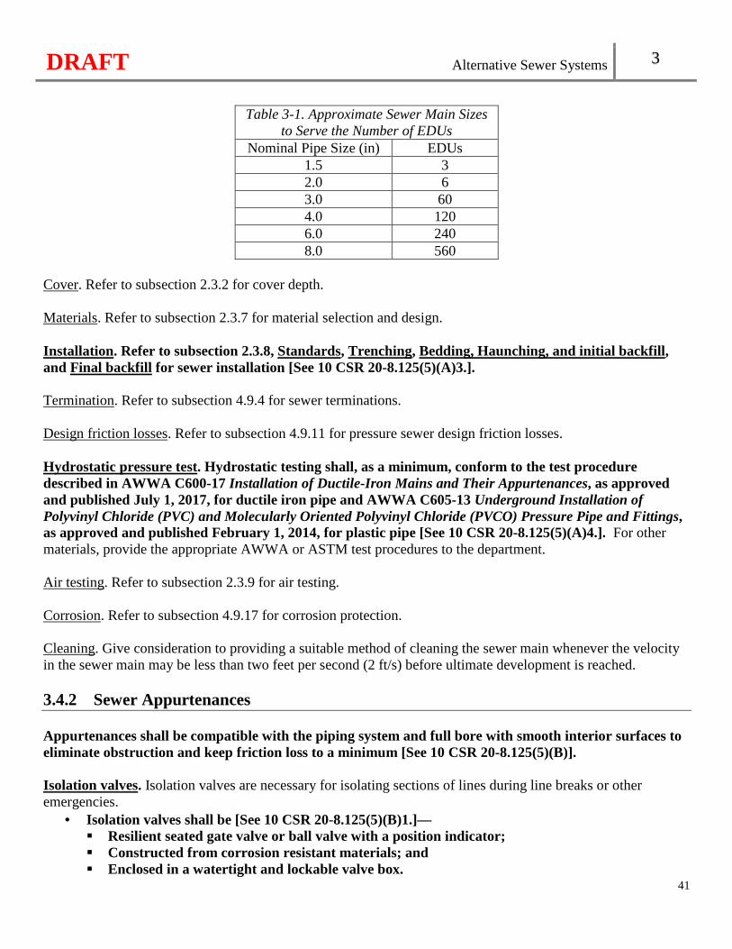
DRAFT Alternative Sewer Systems 3
41
Table 3-1. Approximate Sewer Main Sizes
to Serve the Number of EDUs Nominal Pipe Size (in) EDUs
1.5 3 2.0 6 3.0 60 4.0 120 6.0 240 8.0 560
Cover. Refer to subsection 2.3.2 for cover depth. Materials. Refer to subsection 2.3.7 for material selection and design. Installation. Refer to subsection 2.3.8, Standards, Trenching, Bedding, Haunching, and initial backfill, and Final backfill for sewer installation [See 10 CSR 20-8.125(5)(A)3.]. Termination. Refer to subsection 4.9.4 for sewer terminations. Design friction losses. Refer to subsection 4.9.11 for pressure sewer design friction losses. Hydrostatic pressure test. Hydrostatic testing shall, as a minimum, conform to the test procedure described in AWWA C600-17 Installation of Ductile-Iron Mains and Their Appurtenances, as approved and published July 1, 2017, for ductile iron pipe and AWWA C605-13 Underground Installation of Polyvinyl Chloride (PVC) and Molecularly Oriented Polyvinyl Chloride (PVCO) Pressure Pipe and Fittings, as approved and published February 1, 2014, for plastic pipe [See 10 CSR 20-8.125(5)(A)4.]. For other materials, provide the appropriate AWWA or ASTM test procedures to the department. Air testing. Refer to subsection 2.3.9 for air testing. Corrosion. Refer to subsection 4.9.17 for corrosion protection. Cleaning. Give consideration to providing a suitable method of cleaning the sewer main whenever the velocity in the sewer main may be less than two feet per second (2 ft/s) before ultimate development is reached. 3.4.2 Sewer Appurtenances Appurtenances shall be compatible with the piping system and full bore with smooth interior surfaces to eliminate obstruction and keep friction loss to a minimum [See 10 CSR 20-8.125(5)(B)]. Isolation valves. Isolation valves are necessary for isolating sections of lines during line breaks or other emergencies.
• Isolation valves shall be [See 10 CSR 20-8.125(5)(B)1.]— � Resilient seated gate valve or ball valve with a position indicator; � Constructed from corrosion resistant materials; and � Enclosed in a watertight and lockable valve box.
DRAFT Alternative Sewer Systems 3
42
• Isolation valves shall [See 10 CSR 20-8.125(5)(B)2.]— � On the upstream side of major pipe intersections; � On both sides of stream, bridge, and railroad crossings, and unstable soil; and � On the terminal end of the system to facilitate future extensions.
• Proper support (e.g., crushed stone, concrete pads, or a well compacted trench bottom) shall be provided for valves so the weight of the valve not carried by the pipe [See 10 CSR 20-8.125(5)(B)3.].
Cleanouts. Accumulation of grease and solids will reduce the pressure sewer system capacity by increasing friction losses. Access to pipeline cleaning is provided by cleanouts.
• Cleanouts should be installed at the end of each line, at changes in pipe size, and at pipe intersections. • Enclose a cleanout in a watertight valve box with a locking cap. • Provide cleanouts with proper support (e.g., crushed stone, concrete pads, or a well compacted trench
bottom). Air and Vacuum Relief Valve. Refer to subsection 4.9.3 for air and vacuum relief valve design and installation. Anchoring. Refer to subsection 4.9.9 for anchoring pressure sewers. Pressure monitoring stations. Pressure monitoring stations are recommended to identify areas where air-induced headloss may be occurring. When utilized, design pressure monitoring stations with an access vault to the collection piping and include a threaded tap for a pressure gauge. 3.4.3 Service Line Connection Refer to subsection 2.3.9, Service connections [See 10 CSR 20-8.125(5)(C)]. Install a check valve and isolation valve on each service line. Refer to subsection 3.4.2, Isolation valves for more information on isolation valves. The minimum diameter service line pipe shall not be less than one and one quarter inches (1.25") [See 10 CSR 20-8.125(5)(C)]. 3.4.4 Grinder Pump Stations Type. Both centrifugal pumps and progressing cavity semi-positive displacement pumps may be used in pressure sewer systems. The centrifugal pump, a pump having a maximum head at no flow, may be considered for its ability to compensate with reduced or zero (0) delivery against excessive high pressures and the ability to deliver at a high rate during low flow situations in the collection system, thus enhancing scouring during low flow periods. The progressing cavity semi-positive displacement pump may be considered for its relatively constant rate of delivery in situations in which this feature is considered necessary. The semi-positive displacement pump has no significant increases in delivery against low-flow system conditions to enhance scour during minimum flow times. Number of pumps.
• Simplex grinder pump station shall [See 10 CSR 20-8.125(5)(D)1.A.]—
DRAFT Alternative Sewer Systems 3
43
� Not serve multiple EDUs if owned, operated, and maintained by individual homeowners; and � Not serve commercial facilities.
• Multiple unit grinder pump stations must be owned, operated, and maintained by an approved continuing authority. See Chapter 3, Continuing Authority for more continuing authority information [See 10 CSR 20-8.125(5)(D)1.B.]. � Provide duplex grinder pump stations serving all other service connections (i.e. multiple EDUs,
duplexes, apartment complexes, commercial facilities, etc.) with at least two (2) grinder pumps. � Provide grinder pump units of the same size where only two (2) grinder pump units are provided.
Provide grinder pump units with capacity such that, with any unit out-of-service, the remaining units will have capacity to handle the design peak hourly flow.
Location. Locate grinder pump stations outdoors and in sight of the structure it is serving with consideration given to future maintenance accessibility. Construction materials.
• Grinder pump vaults are typically constructed from fiberglass reinforced polyester, high density polyethylene, steel, or concrete. A fiberglass reinforced polyester pump vault should have a maximum diameter of four feet (4').
• Utilize corrosion-resistant materials for all pipes and appurtenances within a grinder pump station. Austenitic stainless steel of type 316 or 304 is standard for metal components. Nylon is degraded by hydrogen sulfide and is not acceptable.
• Contact between dissimilar metals should be avoided or other provisions made to minimize galvanic action.
Grinder pump vaults shall be watertight [See 10 CSR 20-8.125(5)(D)2.]. Access. A minimum access diameter of twenty-four inches (24") shall be provided for all grinder pump vaults [See 10 CSR 20-8.125(5)(D)3.]. A minimum access diameter of forty-eight inches (48") is recommended for duplex grinder pump vaults. Vault cover. Provide bolt-down cover assemblies or locked covers. The use of high density polyethylene vault covers is discouraged. Ventilation. Provide all grinder pump vaults with provisions for air displacement to the atmosphere, such as an inverted and screened “j” tube or other means. Storage volume. A grinder pump vault must have a storage volume of at least seventy (70) gallons [See 10 CSR 20-8.125(5)(D)4.]. Pump removal. Refer to subsection 4.3.2. Valves. The following valves must be provided in the grinder pump vaults [See 10 CSR 20-8.125(5)(D)5.]:
• A shutoff valve accessible from the ground surface; • A check valve to prevent backflow; and • An anti-siphon valve, where siphoning could occur.
Grinder pump construction. Refer to subsection 4.3.1 for design of pumps and motors [See 10 CSR 20-8.125(5)(D)6.].
DRAFT Alternative Sewer Systems 3
44
Pump openings. The grinder pump unit is expected to be capable of reducing entering materials will pass through without plugging or clogging the pump or pressure sewer system. Do not use screens or other devices requiring regular maintenance to keep trash or stringy material out of the grinder pump or sewer main. Controls. Refer to subsection 4.1.4 for water level control design [See 10 CSR 20-8.125(5)(D)7.]. Electrical equipment. Refer to subsection 4.3.4 for electrical equipment [See 10 CSR 20-8.125(5)(D)8.]. Pump station control panels should be provided with a portable generator receptacle. Flow measurement. Refer to subsection 4.1.9 for flow measurement. Alarm systems. Alarm systems with a backup power source shall be provided for all grinder pump stations [See 10 CSR 20-8.125(5)(D)9.].
• The alarm is expected to activate in cases of power failure, high water levels, pump failure, or any other cause of grinder pump station malfunction.
• Provide an audio-visual alarm system at a minimum. • When the continuing authority operates and maintains the grinder pump stations, post a sign at each
grinder pump station in a clearly visible location, listing a telephone number to be called if the alarm is seen or heard.
Emergency operations. When the continuing authority operates and maintains the grinder pump stations, provisions must be made for periods of mechanical or power failure [See 10 CSR 20-8.125(5)(D)10.]. Acceptable alternatives are as follows:
• Provide additional storage capacity where power outages occur frequently (twenty-four (24)-hour storage capacity is recommended);
• Provide a portable generator to connect to each grinder pump station for a short term during an extended outage; or
• Provide a portable pump to connect to each grinder pump station by means of quick coupling portable pump connections on the discharge.
Spare parts. When the continuing authority operates and maintains the grinder pump stations, provide an inventory of five percent (5%) of the number of grinder pumps in operation for each model installed with a minimum of two (2) grinder pumps. All working parts of the grinder pump stations should be on hand in sufficient quantity.
3.5 Septic Tank Effluent Pumped (STEP) Sewers 3.5.1 Sewer Design Refer to subsection 3.4.1 [See 10 CSR 20-8.125(6)(A)]. 3.5.2 Sewer Appurtenances Refer to subsection 3.4.2 [See 10 CSR 20-8.125(6)(B)].
DRAFT Alternative Sewer Systems 3
45
3.5.3 Service Line Connection Refer to subsection 3.4.3 [See 10 CSR 20-8.125(6)(C)]. 3.5.4 Septic Tank Design In addition to the requirements of section 9.1, septic tank design shall meet the following [See 10 CSR 20-8.125(6)(D)]:
• A single septic tank serving no more than one (1) EDU; and • A capacity of at least one thousand (1,000) gallons. Provide twenty percent (20%) of the septic
tank volume for freeboard and ventilation. 3.5.5 Existing Septic Tanks When existing on-site septic tanks are proposed for reuse in an alternative sewer system, they must be inspected and verified watertight prior to acceptance. Refer to subsection 3.5.4 for the minimum design of acceptable existing septic tanks proposed for reuse [See 10 CSR 20-8.125(6)(E)]. Existing septic tanks may be a source of infiltration and inflow without proper inspection. 3.5.6 Pump Vault Design Locate the pump vault within the septic tank at the outlet or outside the septic tank in a separate pump vault. Protect the pump by means of an outlet screen. Number of pumps. Duplex pumps shall be provided where the design flow from the EDUs, or other, is one thousand five hundred (1,500) gallons per day or greater [See 10 CSR 20-8.125(6)(F)1.]. Construction materials. Pump vaults are typically constructed from fiberglass reinforced polyester or high density polyethylene. Access. Refer to subsection 3.4.4, Access [See 10 CSR 20-8.125(6)(F)2.]. Vault cover. Refer to subsection 3.4.4, Vault Cover. Pump removal. Refer to subsection 4.3.2 [See 10 CSR 20-8.125(6)(F)3.]. Valves. Refer to subsection 3.4.4, Valves [See 10 CSR 20-8.125(6)(F)4.]. Pump construction. Refer to subsection 4.3.1 for design of pumps and motors. Controls. Refer to subsection 4.1.4 for water level control design [See 10 CSR 20-8.125(6)(F)5.]. Electrical equipment. Refer to subsection 4.3.4 for electrical equipment [See 10 CSR 20-8.125(6)(F)6.]. Flow measurement. Refer to subsection 4.1.9 for flow measurement. Alarm systems. Refer to subsection 3.4.4, Alarm systems [See 10 CSR 20-8.125(6)(F)7.].
DRAFT Alternative Sewer Systems 3
46
Emergency operations. Provisions must be made for periods of mechanical or power failure [See 10 CSR 20-8.125(6)(F)8.]. Spare parts. Refer to subsection 3.4.4, Spare parts.
3.6 Septic Tank Effluent Gravity (STEG) Sewers 3.6.1 Sewer Design Sewer mains may be laid with a variable grade, as long as a positive head exists to drive the wastewater toward a terminal location, which allows the sewer to follow the natural topography of the area. Velocity. The maximum velocity in any portion of the system shall be thirteen feet per second (13 ft/s) with velocity protection [See 10 CSR 20-8.125(7)(A)1.]. Minimum size. The minimum diameter sewer main pipe shall not be less than four inches (4") [See 10 CSR 20-8.125(7)(A)2.]. Cover. Refer to subsection 2.3.2 for cover depth. Materials. Refer to subsection 2.3.7 for material selection and design. Installation. Refer to subsection 2.3.8, Standards, Trenching, Bedding, haunching, and initial backfill, and Final backfill for sewer installation[See 10 CSR 20-8.125(7)(A)3.]. Termination. Refer to subsection 4.8.4 for sewer terminations. Curvilinear alignment. Refer to subsection 2.3.5 for curvilinear alignment. Leakage tests. Refer to subsection 2.3.9 for leakage testing [See 10 CSR 20-8.125(7)(A)4.]. Corrosion. Refer to subsection 4.9.17 for corrosion protection. Cleaning. Refer to subsection 3.4.1, Cleaning. 3.6.2 Sewer Appurtenances Refer to subsection 3.4.2. When manholes are utilized at major junctions of sewer mains, refer to section 2.4 [See 10 CSR 20-8.125(7)(B)]. 3.6.3 Service Line Connection Refer to subsection 3.4.3 [See 10 CSR 20-8.125(7)(C)]. The diameter of service line pipe shall not be less than four inches (4") [See 10 CSR 20-8.125(7)(C)1.].
DRAFT Alternative Sewer Systems 3
47
3.6.4 Septic Tank Design Refer to subsection 3.5.4 through 3.5.5 [See 10 CSR 20-8.125(7)(D)].
3.7 Combination of Sewers 3.7.1 Gravity Sewers The combination of gravity sewers and any alternative sewer system is acceptable. 3.7.2 STEP and STEG The combination of STEP and STEG sewer system is common and acceptable since both designs use septic tanks and effluent sewers. 3.7.3 Pressure Sewers STEP and STEG sewers systems discharging to a downstream pressure sewer system is acceptable. A pressure sewer system discharging to a downstream STEP and STEG sewer system shall not be permitted, as effluent sewers are not designed to carry settleable solids and grease [See 10 CSR 20-8.125(8)].
3.8 Vacuum Sewers The Department will evaluate vacuum sewers on a case-by-case basis. Design standards, operating data, and experience for this system are not well established in Missouri. Refer to section 1.4 for new and innovative technology.

DRAFT
48
DRAFT Pumping Stations 4
Chapter 4: Pumping Stations
49
Flood Protection. Refer to Chapter 5 for flood protection [See 10 CSR 20-8.130(2)(A)]. Access Road. Refer to Chapter 5 for access roads to pump station sites [See 10 CSR 20-8.130(2)(B)]. Security. Restrict pump station access, including all mechanical and electrical equipment, by unauthorized persons, discourage vandalism, and prohibit the entrance of animals. It is recommended that security fencing and access hatches with locks be provided. Refer to subsection 5.6.1 for fencing. Grit. Where it is necessary to pump wastewater prior to grit removal, design the wet well and pump station piping to avoid operational problems from the accumulation of grit. Safety. Refer to section 5.6 [See 10 CSR 20-8.130(2)(C)]. Potable Water Sources. The distance between wastewater pumping stations and all potable water sources should be one hundred feet (100') and shall be at least fifty feet (50') in accordance with 10 CSR 23-3.010(2)(A)5. [See 10 CSR 20-8.130(2)(D)]. Housed Wet Wells. Design housed wet well ventilation in accordance with subsection 5.6.10 [See 10 CSR 20-8.130(2)(E)]. Erosion Control During Construction. Refer to subsection 5.3.7. Grading and Landscaping. Upon completion of construction, refer to subsection 5.3.8.
4.1 Design 4.1.1 Type Wastewater pumping stations in general use fall into four (4) types— wet well/dry well, submersible, suction lift, and screw pump. 4.1.2 Structures Separation. Dry wells, including their superstructure, shall be completely separated from the wet well with gas-tight common walls [See 10 CSR 20-8.130(3)(A)1.]. Equipment removal. Facilitate the removal of pumps, motors, and other mechanical and electrical equipment without interference with the continued operation of the remaining pumps. Components located inside buildings or other structures are expected to be removable without affecting the structural integrity of the building. Refer to subsection 5.3.2 for unit isolation. Access and safety landings.
DRAFT Pumping Stations 4
50
• Access. Suitable and safe means of access for persons wearing self-contained breathing apparatus shall be provided to dry wells and to wet wells [See 10 CSR 20-8.130(3)(A)2.]. Access to wet wells containing either screening devices or mechanical equipment requiring inspection or maintenance is to conform to subsection 6.1.1, Access.
• Safety landings. For built-in-place pump stations, provide a stairway to the dry well with rest landings at vertical intervals not to exceed twelve feet (12'). For factory-built pump stations over fifteen feet (15') deep, provide a rigidly fixed landing at vertical intervals not to exceed ten feet (10'). Where a landing is used, provide a suitable and rigidly fixed barrier to prevent individuals from falling past the intermediate landing to a lower level. A manlift or elevator may be used in lieu of landings in a factory-built station, provided emergency access is included in the design. Comply with federal, state, and local safety codes (also see subsection 5.5.7).
Buoyancy. Evaluate buoyancy of the wastewater pumping station structures and, if necessary, make adequate provisions for protection where high groundwater conditions are anticipated. Construction materials. Refer to subsection 5.3.4. 4.1.3 Pumps Multiple units.
• Multiple pumps shall be provided except for design average flows of less than fifteen hundred (1,500) gallons per day [See 10 CSR 20-8.130(3)(C)].
• Where only two (2) units are provided, select units of the same size and capacity such that, with any unit out-of-service, the remaining units will have capacity to handle the design peak hourly flow.
• All pumps should be tested by the manufacturer. These tests should include a hydrostatic test and an operating test.
• Single pump installations may be given consideration only where the design average flow of the pump station is less than fifteen hundred (1,500) gallons per day and only if the pump station is designed to permit the installation of a future duplicate unit without structural change and satisfactory means are provided to detect malfunctions and take corrective actions before an overflow to waters of the state could occur.
Protection against clogging.
• Combined wastewater. Pumps handling combined wastewater should be preceded by readily accessible screening devices to protect the pumps from clogging or damage. Screening devices should have clear openings as provided in subsection 6.1.2, Bar spacing. Where a screening device is installed, provide a mechanical hoist. Where the size of the installation warrants, provide mechanically cleaned and/or duplicate screening devices.
• Separate sanitary wastewater. Protect pumps handling separate sanitary wastewater from thirty inches (30") diameter or larger sewers by a screening device meeting the above recommendations. Consider appropriate protection from clogging for small pumping stations.
• For pump stations with screening devices, provide a method to remove, store, and dispose of screenings in accordance with subsection 6.1.1, Screenings removal and disposal.
Pump openings. Design pumps, other than grinder pumps, handling raw wastewater capable of passing solid spheres of at least three inches (3") in diameter. Pump suction and discharge openings should be at least four
DRAFT Pumping Stations 4
51
inches (4") in diameter. An exception to the design for passing solid spheres of at least three inches (3") in diameter may be made on a case-by-case basis when the design includes piping with a diameter at least one inch (1") greater than the size of the solid sphere and equivalent protection from clogging or damage (i.e., grinder pumps, screening device, etc.) is provided. Priming. Place the pump, other than suction lift pumps, so that under normal operating conditions it will operate under a positive suction head. Electrical equipment. The following shall be met [See 10 CSR 20-8.130(3)(B)2.]:
• Refer to subsection 5.5.2; • Utilize corrosive resistant equipment located in the wet well; • Provide a watertight seal and separate strain relief for all flexible cable; • Install a fused disconnect switch located above ground for the main power feed for all pumping
stations; • When such equipment is exposed to weather, comply with the requirements of weather proof
equipment National Electrical Manufacturers Association (NEMA) 4 at a minimum and 4X where necessary; NEMA Standard 250-2014, published December 15, 2014. This standard is incorporated by reference in this rule, as published by National Electrical Manufacturers Association, 1300 North 17th Street, Arlington, VA 22209;
• Install lightning and surge protection systems; • Install a one hundred ten volt (110 V) power receptacle inside the control panel located outdoors
to facilitate maintenance; and • Provide Ground Fault Circuit Interruption (GFCI) pr otection for all outdoor outlets.
Intake. Each pump should have an additional individual intake. Design the wet well and intake to avoid turbulence near the intake and to prevent vortex formation. Dry well dewatering. Provide a sump pump equipped with dual check valves in the dry well to remove leakage or drainage with the discharge above the maximum high water level of the wet well. Water ejectors connected to a potable water supply will not be approved. Slope all floor and walkway surfaces to a point of drainage. Pipe or channel pump seal leakage directly to the sump. Size the sump pump to remove the maximum pump seal water discharge that could occur in the event of a pump seal failure. Refer to subsection 4.5.1 for alarm systems activation. Locate sump pumps to provide easy access and removal. Operate the sump pump automatically by use of a level control. Pumping rates. The pumps and controls of main pumping stations, especially pumping stations operated as part of treatment facilities, should be selected to operate at varying delivery rates. Design such stations to deliver as uniform a flow as practicable in order to minimize hydraulic surges. Base the station design capacity on the peak hourly flow determined in accordance with section 1.1 and size adequately to maintain a minimum velocity of two feet (2') per second in the force main. Refer to subsection 4.8.1. 4.1.4 Controls Water level controls must be accessible without entering the wet well [See 10 CSR 20-8.130(3)(C)]. Locate water level control sensing devices to prevent undue affects from turbulent flows entering the wet well or by the turbulent suction of the pumps. For bubbler type level monitoring systems, include dual air compressors. Make
DRAFT Pumping Stations 4
52
provisions to automatically alternate the pumps in use. Suction lift stations should be designed to alternate pumps daily instead of each pumping cycle to extend the life of the priming equipment. 4.1.5 Pipe Size Size pump suction and discharge piping not less than four inches (4") in diameter except as approved under subsection 4.1.3, Pump openings, where grinder pumps are used, or design of specialized equipment allows. Maximum recommended velocities are six feet (6') per second in the suction line and eight feet (8') per second in the discharge line. Design the minimum velocity not less than two feet (2') per second in the discharge line. 4.1.6 Valves Location. Valves shall not be located in the wet well unless integral to a pump or its housing. [See 10 CSR 20-8.130(3)(D)]. Suction line. Place suitable shutoff valves on the suction line of dry well pumps. Discharge line. Place suitable shutoff and check valves on the discharge line of each pump, other than screw pumps. Locate the check valve between the shutoff valve and the pump. Select check valves suitable for the material being handled and place the check valve on the horizontal portion of discharge piping except for ball checks, which may be placed in the vertical run. Valves are expected to be capable of withstanding normal pressures and water hammer. Locate all shutoff and check valves to be operable from floor level and accessible for maintenance. Outside levers are recommended on swing check valves. 4.1.7 Wet Wells Divided wells. Where continuity of pumping station operation is critical, evaluate dividing the wet well into multiple interconnected sections to facilitate repairs and cleaning. Size.
• Evaluate the design fill time and minimum pump cycle time in sizing the wet well. Base the effective volume of the wet well on the design average flow determined in accordance with section 1.1 and a filling time not to exceed thirty (30) minutes, unless the pumping station is designed to provide flow equalization. Utilize the pump manufacturer’s duty cycle recommendations when selecting the minimum cycle time.
• For constant speed pumps, base the minimum pump cycle volume on Equation 4-1.
V = (T x Q) / 4 Equation 4-1. Minimum pump cycle volume. Where:
V = storage volume between Pump ON and Pump OFF (gallons) T = time between starts (minutes) Q = pump discharge capacity or the difference in flow rate between steps (gallons per minute)
DRAFT Pumping Stations 4
53
• When the anticipated initial flow tributary to the pumping station is less than the design average flow, make provisions so that the fill time indicated is not exceeded for initial flows. Evaluate detention times for initial and ultimate flow conditions.
• When the wet well is designed for flow equalization or when wastewater will remain in the wet well for extended periods, make provisions to prevent septicity.
Floor slope. Design the wet well floor with a minimum slope of one to one (1:1) to the hopper bottom. The horizontal area of the hopper bottom should be no greater than necessary for proper installation and function of the inlet. High water level. Typically, the high water level control in the wet well during normal operations is at least one foot (1') below the invert of the incoming sewer. Air displacement. Covered wet wells shall have provisions for air displacement to the atmosphere, such as an inverted and screened “j” tube or other means [See 10 CSR 20-8.130(3)(E)]. 4.1.8 Ventilation Interconnection between the wet well and dry well ventilation systems is not acceptable. See requirements in subsection 5.6.10 [See 10 CSR 20-8.130(3)(F)]. In addition to the requirements in subsection 5.6.10, the design should include the following:
• General. Provide adequate ventilation for all pump stations. Provide mechanical ventilation for dry wells that are located below the ground surface. If screens or mechanical equipment requiring maintenance or inspection are located in the wet well, install permanent ventilation equipment; � Wet wells. Wet well ventilation may be either continuous or intermittent; Force air into the wet well
by mechanical means rather than solely exhausted from the wet well. Base air change demands on one hundred percent (100%) fresh air. o Where continuous ventilation is needed, provide at least twelve (12) complete air changes per
hour; o Where ventilation is intermittent, provide at least thirty (30) complete air changes per hour; o Ensure portable ventilation equipment is available for use at submersible pump stations and wet
wells with no permanently installed ventilation equipment; and � Dry wells. In dry wells over fifteen feet (15') deep, multiple inlets and outlets are desirable. Dry well
ventilation may be either continuous or intermittent. Base air change demands on one hundred percent (100%) fresh air; o Where continuous ventilation is needed, provide at least six (6) complete air changes per hour; o Where ventilation is intermittent, provide at least thirty (30) complete air changes per hour. A
system of two (2) speed ventilation with an initial ventilation rate of thirty (30) changes per hour for ten (10) minutes and automatic switch over to six (6) changes per hour may be used to conserve heat.
4.1.9 Flow Measurement Provide suitable devices for measuring wastewater flow at all pumping stations as identified in subsection 5.5.9. Equip all pump stations with elapsed time meters at a minimum provided sufficient equipment is in place to measure the duration of individual and simultaneous pump operation.
DRAFT Pumping Stations 4
54
4.1.10 Water Supply There shall be no physical connection between any potable water supply and a wastewater pumping station which, under any conditions, might cause contamination of the potable water supply. If a potable water supply is brought to the station, conform to the conditions stipulated under subsection 5.5.4 [See 10 CSR 20-8.130(3)(G)].
4.2 Suction-Lift Pump Stations Suction-lift pumps shall meet the applicable requirements of section 4.1 [See 10 CSR 20-8.130(4)].
4.2.1 Pump Priming and Lift Requirements Suction-lift pumps are of the self-priming or vacuum-priming type. Suction-lift pump stations using dynamic suction lifts exceeding the limits outlined in section 4.2 may be approved by the Department upon submission of factory certification of pump performance and detailed calculations indicating satisfactory performance under the proposed operating conditions in the summary of design. Include such detailed calculations of static suction-lift as measured from “lead pump off” elevation to center line of pump suction, friction, and other hydraulic losses of the suction piping, vapor pressure of the liquid, altitude correction, required net positive suction head, and a safety factor of at least six feet (6'). 4.2.2 Self-Priming Pumps Self-priming pumps are expected to be capable of rapid priming and repriming at the “lead pump on” elevation. Such self-priming and repriming is to be accomplished automatically under design operating conditions. Suction piping should not exceed the size of the pump suction nor exceed twenty-five feet (25') in total length. For priming lift at the “lead pump on” elevation, include a safety factor of at least four feet (4') from the maximum allowable priming lift for the specific equipment at design operating conditions. The combined total of dynamic suction lift at the “pump off” elevation and required net positive suction head at design operating conditions shall not exceed twenty-two feet (22') [See 10 CSR 20-8.130(4)(A)]. 4.2.3 Vacuum-Priming Pumps Vacuum-priming pump stations shall be equipped with dual vacuum pumps capable of automatically and completely removing air from the suction-lift pump [See 10 CSR 20-8.130(4)(B)]. Adequately protect the vacuum pumps from damage due to wastewater. 4.2.4 Equipment, Wet Well Access, and Valve Location Equipment. Locate the pump equipment compartment above grade or offset and effectively isolate from the wet well to prevent a hazardous and corrosive sewer atmosphere from entering the equipment compartment. Wet well access. Wet well access shall not be through the equipment compartment and shall be at least twenty-four inches (24") in diameter [See 10 CSR 20-8.130(4)(C)1.]. Provide gasketed replacement plates to cover the opening to the wet well for pump units removed for servicing.
DRAFT Pumping Stations 4
55
Valve location. Valves shall not be located in the wet well [See 10 CSR 20-8.130(4)(C)2.].
4.3 Submersible Pump Stations Submersible pump stations shall meet the applicable requirements under section 4.1, except as modified in section 4.3 [See 10 CSR 20-8.130(5)]. 4.3.1 Construction Design submersible pumps and motors specifically for raw wastewater use, including totally submerged operation during a portion of each pumping cycle, and to meet the requirements of the NEC for such units. Provide an effective method to detect shaft seal failure or potential seal failure. No portion of the pump should bear directly on the floor. 4.3.2 Pump Removal Submersible pumps shall be readily removable and replaceable without personnel entering or dewatering the wet well or disconnecting any piping in the wet well [See 10 CSR 20-8.130(5)(A)]. 4.3.3 Ventilation Provide submersible pump wet wells with static vents if mechanical ventilation is not provided. Also refer to subsection 4.1.8. 4.3.4 Electrical Equipment Power supply and control circuitry. Design electrical supply, control, and alarm circuits to provide strain relief and to allow disconnection from outside the wet well. Protect terminals and connectors from corrosion by locating them outside the wet well or through use of watertight seals. Controls. Locate the motor control center outside the wet well to be readily accessible and to be protected by a conduit seal or other appropriate measures meeting the requirements of the NEC, to prevent the atmosphere of the wet well from gaining access to the control center. Locate the seal so that the motor can be removed and electrically disconnected without disturbing the seal. When such equipment is exposed to weather, meet the requirements of weather proof equipment NEMA 4 at a minimum and 4X where necessary. See subsection 4.1.3 for NEMA information. Power cord. Design pump motor power cords for flexibility and serviceability under conditions of extra hard usage and to meet the requirements of the NEC standards for flexible cords in wastewater pump stations. Use ground fault interruption protection to de-energize the circuit in the event of any failure in the electrical integrity of the cable. Use corrosion resistant power cord terminal fittings and construct in a manner to prevent the entry of moisture into the cable. Provide a power cord with strain relief appurtenances and design to facilitate field connecting.
DRAFT Pumping Stations 4
56
4.3.5 Valve Chamber and Valves Valves required under subsection 4.1.6 shall be located in a separate valve chamber [See 10 CSR 20-8.130(5)(B)]. Drain. Make provisions to remove or drain accumulated water from the valve chamber. The valve chamber may be dewatered to the wet well through a drain line such that gases or overflows from the wet well do not enter the valve chamber. Integral check valves. Check valves that are integral to the pump need not be located in a separate valve chamber provided that the valve can be removed from the wet well in accordance with subsection 4.3.2. Access. A minimum access hatch dimensions of twenty-four inches by thirty-six inches (24" x 36") shall be provided[See 10 CSR 20-8.130(5)(B)1.]. Provide access in accordance with subsection 4.1.2, Access. Ventilation. Valve chambers with piping eight inches (8") (20 cm) in diameter or greater should consider ventilation in accordance with subsection 4.1.8, Dry wells. Portable pump connection. A portable pump connection on the discharge line with rapid connection capabilities shall be provided in the valve chamber [See 10 CSR 20-8.130(5)(B)2.]. Refer to subsection 4.6.3. Valve chamber construction materials. Valve chambers are typically constructed from concrete or fiberglass reinforced polyester. Piping supports. Provide adequate support for the discharge lines and valves. Supports are expected to be of corrosion resistant material. Contact between dissimilar metals should be avoided or other provisions made to minimize galvanic action. Valve chambers are expected to be watertight.
4.4 Screw Pump Stations Screw pump stations are expected to meet the applicable requirements of section 4.1. 4.4.1 Covers Provide covers or other means of excluding direct sunlight as necessary to eliminate adverse effects caused by temperature changes. 4.4.2 Pump Wells Provide a positive means of isolating individual screw pump wells.
DRAFT Pumping Stations 4
57
4.4.3 Bearings Lubricate submerged bearings by means of an automated system without pump well dewatering. 4.4.4 Discharge Line Make suitable provisions to prevent backflow down the trough of a pump that is out-of-service.
4.5 Alarm Systems 4.5.1 General Alarm systems with a backup power source shall be provided for pumping stations [See 10 CSR 20-8.130(6)]. The alarm is expected to be activated in cases of power failure, dry well sump and wet well high water levels, pump failure, or any other cause of pump station malfunction. 4.5.2 Transmitting System Provide pumping station alarm systems that transmit and identify alarm conditions to a facility that is staffed twenty-four (24) hours a day. If such a facility is not available and twenty-four (24)-hour holding capacity, based on the design average flow, is not provided, transmit the alarm to offices during normal working hours and to the phone of the responsible person(s) in charge of the pumping station during off-duty hours. 4.5.3 Audio-visual System Audio-visual alarm systems may be acceptable in some cases in lieu of the transmitting system depending upon location, station holding capacity, and inspection frequency with Department approval. Post a sign at each pump station in a clearly visible location, listing a telephone number to be called if the alarm is seen or heard.
4.6 Emergency Operation 4.6.1 Objective The objective of emergency operation is to prevent the discharge of raw or partially treated wastewater to any waters of the state and to protect public health by preventing sanitary sewer overflows of wastewater and subsequent discharge to basements, streets, and other public and private property. 4.6.2 Emergency Pumping Capability Emergency pumping capability is expected unless on-system overflow prevention is provided by adequate storage capacity. Emergency pumping capability may be accomplished by connection of the pump station to at least two (2) independent utility substations, by provision of portable or in-place internal combustion engine
DRAFT Pumping Stations 4
58
equipment to generate electrical or mechanical energy, or by the provision of portable pumping equipment. Comply with the conditions stipulated in subsection 5.5.1 for emergency power facilities. For emergency standby systems, provide sufficient capacity to start up and maintain the total rated running capacity of the pump station. 4.6.3 Portable Pump Connection Regardless of the type of emergency standby system, provide a portable pump connection to the force main with rapid connection capabilities and appropriate valves outside the dry well and/or wet well. 4.6.4 Portable Standby Equipment Only utilize portable standby equipment when the continuing authority has responsible personnel capable of responding twenty-four (24) hours a day. If portable standby equipment are used for multiple facilities (i.e. pumping stations, City Hall, etc.), the wastewater utility should evaluate its pump stations to determine the number and size of portable equipment needed to prevent sanitary sewer overflows during a period of power outage. 4.6.5 Emergency High Level Overflows Evaluate a controlled, high-level wet well overflow to supplement alarm systems and emergency pumping capability in order to prevent backup of wastewater into basements, or other discharges that could cause severe adverse impacts on public interests, including public health and property damage for use during possible periods of extensive power outages, mandatory power reductions, or uncontrollable emergency conditions. Where a high level overflow is utilized, drain the storage/detention tanks or basins back to the pump station wet well. All structures capable of bypassing shall be controlled by a lockable, manually operated valve. Where such overflows are considered, contact the Department for the necessary treatment or storage requirements [See 10 CSR 20-8.130(7)(A)1.]. In addition to the required emergency means of operation, where overflows may affect public water supplies, a high level wet well overflow and a storage/detention basin or tank, the following minimum retention time shall be provided [See 10 CSR 20-8.130(7)(A)2.]:
• For facilities with a design average flow one hundred thousand (100,000) gallons per day or greater, a storage capacity for two (2)-hour retention of the peak hourly flow; or
• For facilities with a design average flow of less than one hundred thousand (100,000) gallons per day, a storage capacity for four (4)-hour retention of the peak hourly flow.
4.6.6 Storage Capacity A holding basin with capacity for twenty-four (24)-hour retention of peak hourly flow may be utilized as an emergency operation. Design the basin to drain back by gravity into the wet well or collection system.
DRAFT Pumping Stations 4
59
4.6.7 Equipment Requirements General. The following applies to all internal combustion engines used to drive auxiliary pumps, service pumps through special drives, or electrical generating equipment:
• Engine protection. Protect the engine from operating conditions that would result in damage to equipment. Unless continuous manual supervision is planned, provide protective equipment capable of shutting down the engine and activating an alarm as required in section 4.5. Monitor for conditions of low oil pressure and overheating with protective equipment. Oil pressure monitoring will not be necessary for engines with splash lubrication;
• Placement. Bolt standby generators in place. Provide facilities for unit removal for purposes of major repair or routine maintenance;
• Controls. Assess provisions for automatic and manual startup and cut-in; • Size. Size the engine with adequate rated power to start and continuously operate under all connected
loads including lighting and ventilating systems in addition to pumping requirements; • Fuel type. Consider reliability and ease of starting, especially during cold weather conditions, in the
selection of the type of fuel. Where public utility gas is selected, give consideration to a generator design that may be operated with an alternate fuel supply system in accordance with the NEC;
• Underground fuel storage. For underground fuel storage and piping facilities, design, construct, operate, and maintain in accordance with 10 CSR 26-2;
• Engine ventilation. Locate the engine above grade and make adequate provisions for heat dissipation and ventilation of fuel vapors and exhaust gases;
• Routine start-up. Provide all emergency equipment with instructions indicating the need and frequency for regular starting and running of such units at full loads;
• Protection of equipment. Protect emergency equipment from damage at the restoration of regular electrical power; and
• Air quality. Evaluate federal, state, and local regulations regarding air quality. Engine-driven pumping equipment. In addition to subsection 4.6.7, General, the following applies to permanently-installed or portable engine-driven pumping equipment:
• Pumping capacity. Design engine-driven pumps to meet the pumping requirements unless storage capacity is available for flows in excess of pump capacity. Design pumps for anticipated operating conditions, including suction lift if applicable;
• Operation. Equip the engine and pump for automatic start-up and operation of pumping equipment unless manual start-up and operation is justified. Make provisions for manual start-up. Where manual start-up and operation is justified, meet the requirements of section 4.5 and subsection 4.6.7, Portable pumping equipment; and
• Portable pumping equipment. Where part or all of the engine-driven pumping equipment is portable, provide sufficient storage capacity with an alarm system to allow time for detection of pump station failure, transportation, and hookup of the portable equipment, by means of permanent fixtures at the pump station that will facilitate rapid and easy connection.
Engine-driven generating equipment. In addition to subsection 4.6.7, General, the following applies to permanently-installed or portable engine-driven generating equipment:
• Generating capacity.
DRAFT Pumping Stations 4
60
� Adequately size the generating unit to provide power for pump motor starting current and for lighting, ventilation, and other auxiliary equipment necessary for safety and the proper operation of the pump station.
� Justify the operation of only one (1) pump during periods of auxiliary power supply. Such justification may be made on the basis of the design peak hourly flows relative to single-pump capacity, the anticipated length of power outage, and the storage capacity.
� Provide special sequencing controls to start pump motors unless the generating equipment has capacity to start all pumps simultaneously with auxiliary equipment operating;
• Operation. Make provisions for automatic and manual start-up and load transfer unless only manual start-up and operation is justified. Protect the generator from operating conditions that could result in damage to equipment. Consider provisions to allow the engine to start and stabilize at operating speed before assuming the load. Where manual start-up and transfer is justified, the storage capacity and the alarm system shall meet the requirements of section 4.5 and subsection 4.6.7, Portable generating equipment;
• Portable generating equipment. Where portable generating equipment or manual transfer is utilized, provide sufficient storage capacity, with an alarm system, to allow time for detection of pump station failure, transportation, and connection of generating equipment. Use special electrical connections and double throw switches to connect the portable generating equipment. Protect electrical energy generating units against burnout when normal utility services are restored and provide sufficient capacity to power for lighting and ventilating system in addition to the pumping units; and
• Provisions for testing. Include testing provisions in the design of subsection 4.6.7, Engine-driven generating equipment requiring period testing to be accomplished while maintaining electric power to all vital components. Such provisions would involve an ability to conduct tests, such as actuating and resetting automatic transfer switches and starting and loading emergency generating equipment without taking essential equipment off-line. Design the electric power distribution system and equipment to facilitate inspection and maintenance of individual items without interruption of operations.
4.7 Independent Utility Substations Where independent substations are used for emergency power, each separate substation and its associated distribution lines shall be capable of starting and operating the pump station at its rated capacity [See 10 CSR 20-8.130(7)(B)].
4.8 Instructions and Equipment Supply wastewater pumping stations and portable equipment with a complete set of operational instructions, including emergency procedures, and maintenance schedules. Supply tools and spare parts as necessary.
DRAFT Pumping Stations 4
61
4.9 Force Mains 4.8.1 Velocity At design pumping rates, a cleansing velocity of at least two feet (2') per second shall be maintained [See 10 CSR 20-8.130(8)(A)]. A maximum velocity of eight feet (8') per second is recommended to avoid high head loss and protect valves. 4.9.2 Minimum Size The minimum force main diameter for raw wastewater should not be less than four inches (4"), except where grinder pumps are used. 4.9.3 Air and Vacuum Relief Valve Place air relief valves at high points in the force main to prevent air locking. Vacuum relief valves may be necessary to relieve negative pressures on force mains. Evaluate the force main configuration and head conditions for the need and placement of vacuum relief valves. An air or vacuum relief valve should have an isolation valve between the air relief valve and the force main. Install an air or vacuum relief valve inside of a vault that is at least thirty-six inches (36") in diameter and has an access opening at least twenty-four inches (24") in diameter. The vault should have provisions for air displacement to the atmosphere, such as an inverted and screened “j” tube or other means. Space valves at no more than one thousand five hundred foot (1,500') intervals to facilitate initial testing and subsequent maintenance and repairs. The weight of the valve is not be carried by the pipe. Provide valves with proper support, such as crushed stone, concrete pads, or a well compacted trench bottom. 4.9.4 Termination Design the force main to enter the receiving manhole with a smooth flow transition to the gravity sewer system at a point not more than one foot (1') above the flow line. Minimize turbulence and scouring at the point of discharge. Provide corrosion protection for the receiving manhole in accordance with subsection 2.4.8. 4.9.5 Materials Select pipe materials adapted to local conditions, such as character of industrial wastes, soil characteristics, exceptionally heavy external loadings, internal erosion, corrosion, or similar problems. All pipe and joint materials conforms to the appropriate ASTM specifications. Use suitable couplings complying with ASTM specifications for joining dissimilar materials.
DRAFT Pumping Stations 4
62
Design all pipes to prevent damage from superimposed live, dead, and frost-induced loads. Make proper allowance for loads on the pipe, because of soil and potential groundwater conditions, as well as the width and depth of trench. For new pipe or joint materials for which ASTM standards have not been established, provide complete material and installation specifications developed on the basis of criteria adequately documented and certified in writing by the manufacturer to be satisfactory for the specific details plans for approval by the Department. 4.9.6 Installation Refer to subsection 2.3.8, Standards, Trenching, Bedding, haunching, and initial backfill, and Final backfill [See 10 CSR 20-8.130(8)(B)]. 4.9.7 Cover Cover force mains with sufficient earth or other insulation to prevent freezing. 4.9.8 Pipe and Design Pressure Specify pipe and joints equal to water main strength materials suitable for design conditions. Design the force main, reaction blocking, and station piping to withstand water hammer pressures and associated cyclic reversal of stresses that are expected with the cycling of wastewater pump stations. Consider the use of surge valves, surge tanks, or other suitable means to protect the force main against severe pressure changes. 4.9.9 Anchoring Sufficiently anchor force mains within the pumping station and throughout the line length. Limit the number of bends to be as few as possible. Provide thrust blocks, restrained joints, and/or tie rods where restraint is needed. 4.9.10 Special Construction Meet applicable requirements of sections 2.6 and 2.7 for force main construction near streams or used for aerial crossings. 4.9.11 Design Friction Losses Friction coefficient. Base friction losses through force mains on the Hazen-Williams formula or other acceptable method (e.g. the Darcy-Weisbach equation). When the Hazen-Williams formula is used, use the value for “C” as one hundred (100) for unlined iron or steel pipe for design. For other smooth pipe materials (e.g., polyvinyl chloride, polyethylene, lined ductile iron, etc.) a higher “C” value, not to exceed one hundred thirty (130), may be allowed for design. Maximum power requirements. When initially installed, force mains will have a significantly higher “C” factor. The effect of the higher “C” factor should be considered when calculating maximum power requirements and duty cycle time to prevent damage to the motor. Also, consider the effects of higher discharge rates on selected pumps and downstream facilities.
DRAFT Pumping Stations 4
63
4.9.12 Protection of Water Supplies Comply with section 2.8 for separation between water mains and sanitary sewer force mains [See 10 CSR 20-8.130(8)(C)]. 4.9.13 Identification Where force mains are constructed of a material that might cause the force main to be confused with potable water mains, appropriately identify the force main. 4.9.14 Leakage Testing Specify leakage tests including testing methods and leakage limits. Refer to subsection 2.3.9, Leakage tests. 4.9.15 Maintenance Considerations Evaluate the installation of isolation valves where force mains connect into a common force main. Evaluate the installation of cleanouts at low points and chambers for pig launching and catching for any force main to facilitate maintenance. 4.9.16 Cleaning Give consideration to providing a suitable method of cleaning the force main whenever the velocity in the force main may be less than two feet (2') per second before ultimate development is reached. 4.9.17 Corrosion Where corrosive conditions due to septicity or other causes are anticipated, provide corrosion protection of the interior force main. 4.9.18 Locator Wire Where locator wire is utilized, comply with section 2.9.

DRAFT
64
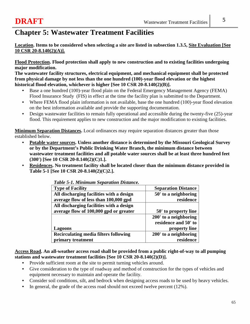
DRAFT Wastewater Treatment Facilities 5
Chapter 5: Wastewater Treatment Facilities
65
Location. Items to be considered when selecting a site are listed in subsection 1.3.5, Site Evaluation [See 10 CSR 20-8.140(2)(A)]. Flood Protection. Flood protection shall apply to new construction and to existing facilities undergoing major modification. The wastewater facility structures, electrical equipment, and mechanical equipment shall be protected from physical damage by not less than the one hundred (100)-year flood elevation or the highest historical flood elevation, whichever is higher [See 10 CSR 20-8.140(2)(B)].
• Base a one hundred (100)-year flood plain on the Federal Emergency Management Agency (FEMA) Flood Insurance Study (FIS) in effect at the time the facility plan is submitted to the Department.
• Where FEMA flood plain information is not available, base the one hundred (100)-year flood elevation on the best information available and provide the supporting documentation.
• Design wastewater facilities to remain fully operational and accessible during the twenty-five (25)-year flood. This requirement applies to new construction and the major modification to existing facilities.
Minimum Separation Distances. Local ordinances may require separation distances greater than those established below.
• Potable water sources. Unless another distance is determined by the Missouri Geological Survey or by the Department’s Public Drinking Water Branch, the minimum distance between wastewater treatment facilities and all potable water sources shall be at least three hundred feet (300') [See 10 CSR 20-8.140(2)(C)1.].
• Residences. No treatment facility shall be located closer than the minimum distance provided in Table 5-1 [See 10 CSR 20-8.140(2)(C)2.].
Table 5-1. Minimum Separation Distance. Type of Facility Separation Distance All discharging facilities with a design average flow of less than 100,000 gpd
50' to a neighboring residence
All discharging facilities with a design average flow of 100,000 gpd or greater 50' to property line
Lagoons
200' to a neighboring residence and 50' to
property line Recirculating media filters following primary treatment
200' to a neighboring residence
Access Road. An all-weather access road shall be provided from a public right-of-way to all pumping stations and wastewater treatment facilities [See 10 CSR 20-8.140(2)(D)].
• Provide sufficient room at the site to permit turning vehicles around. • Give consideration to the type of roadway and method of construction for the types of vehicles and
equipment necessary to maintain and operate the facility. • Consider soil conditions, silt, and bedrock when designing access roads to be used by heavy vehicles. • In general, the grade of the access road should not exceed twelve percent (12%).
DRAFT Wastewater Treatment Facilities 5
66
5.1 Quality of Effluent The degree of wastewater treatment shall be based on 10 CSR 20-7.015, Effluent Regulations, 10 CSR 20-7.031, Water Quality Standards, and/or appropriate federal regulations including the provisions of the operating permit [See 10 CSR 20-8.140(3)].
5.2 Design 5.2.1 Type of Treatment Items to be considered in selection of the appropriate type of treatment are presented in section 1.3 [See 10 CSR 20-8.140(4)(A)]. The facility design is expected to provide the necessary flexibility to perform satisfactorily within the expected range of waste characteristics and volumes. 5.2.2 New and Innovative Technology Refer to section 1.4 [See 10 CSR 20-8.140(4)(B)]. 5.2.3 Design by Analogy Data from similar full scale installations may be utilized in the design of subsequent installations. Provide a thorough investigation that is adequately documented to the Department to establish the reliability and applicability of the data and design. 5.2.4 Design Period Identify the design period in the facility plan per subsection 1.3.2 [See 10 CSR 20-8.140(4)(C)]. 5.2.5 Design Loads Hydraulic design.
• Identify flow conditions critical to the design of the wastewater treatment facility as described in section 1.1 [See 10 CSR 20-8.140(4)(D)1.A.].
• Evaluate initial low flow conditions in the design to minimize operational problems with freezing, septicity, flow measurements, and solids dropout.
• The design peak hourly flows shall be used to evaluate the effect of hydraulic peaks on unit processes, pumping, piping, etc. [See 10 CSR 20-8.140(4)(D)1.B.].
• The design of treatment units that are not subject to peak hourly flow requirements shall be based on the design average flow [See 10 CSR 20-8.140(4)(D)1.C.].
• Specify the design maximum day flows that the facility is to treat on a sustained basis for facilities subject to high wet weather flows or overflow detention pump-back flows.
DRAFT Wastewater Treatment Facilities 5
67
Organic design. Base organic loadings for wastewater treatment facility design on the information given in section 1.1. When septage is accepted at a wastewater treatment facility, the effects of septage flow shall be evaluated in the design [See 10 CSR 20-8.140(4)(D)2.]. For more information on septage, refer to section 6.8. Shock effects. Evaluate the shock effects of high concentrations and diurnal peaks for short periods of time on the treatment process, particularly for small wastewater treatment facilities and batch processes. Flow equalization. Consider flow equalization for the equalization of flows and organic shock loads at all wastewater treatment facilities which are critically affected by surge loadings. Flow equalization sizing should be based on data obtained herein and from section 1.1, section 6.5, and section 6.6. 5.2.6 Conduits Design all piping and channels to carry the maximum expected flows. Design the incoming sewer for unrestricted flow. Fillet bottom corners of the channels, except final effluent channels. Design conduits to avoid creation of pockets and corners where solids can accumulate. Place suitable gates or valves in channels to seal off unused sections which might accumulate solids. The use of shear gates, stop plates, or stop planks is permitted where they can be used in place of gate valves or sluice gates. Use corrosion resistant materials for these control gates. 5.2.7 Arrangement of Units Arrange component parts of the wastewater treatment facility for greatest operating and maintenance convenience, flexibility, economy, continuity of optimum effluent quality for water quality protection, and ease of installation of future units. Provide adequate access and removal space around all components to permit easy operation, inspection, maintenance, and removal and replacement without interfering with the operation of other equipment. Components located inside buildings or other structures should be removable without affecting the structural integrity of the building or creating a safety hazard. 5.2.8 Flexibility Provide a central collection and distribution point including proportional flow splitting for the wastewater flow before each unit operation where duplicate units are designed. Exceptions to this central collection and distribution point requirement may be made on a case-by-case basis when the design incorporates more than one (1) unit process in the same physical structure.
DRAFT Wastewater Treatment Facilities 5
68
5.2.9 Flow Division Control Provide flow division control facilities as necessary to ensure positive, adjustable control of organic and hydraulic loading to the individual process units. Design flow division control facilities for easy operator access, change, observation, and maintenance. The use of upflow division boxes equipped with adjustable sharp-crested weirs or similar devices is recommended. The use of valves for flow splitting is not acceptable. Incorporate appropriate flow measurement facilities in the flow division control design. 5.2.10 Nuisance Control Design should include measures for mitigation arising from the following potential nuisance conditions:
• Collection systems primarily composed of force mains or otherwise provides lengthy retention times; • Preliminary treatment; • Primary treatment; • Trickling filters; • Solids handling and disposal; • Blowers; and • Other processes.
5.3 Details 5.3.1 Installation of Mechanical Equipment The specifications should be written to ensure that the installation and initial operation of major items of mechanical equipment will be inspected and approved by a representative of the manufacturer. 5.3.2 Unit Isolation Removal from service.
• Locate and arrange structures and piping so that each unit of the wastewater treatment facility can be removed from service independently. Design the wastewater treatment facility to operate during unit maintenance and emergency repair.
• Unit isolation may be accomplished through the use of duplicate or multiple treatment units in any stage if the design average flow can be handled hydraulically with the largest unit out-of-service.
• Design all unit isolation systems to permit manual operation in the event of power failure and designed so that the valve will fail as is, upon failure of the power operator.
• Assess the need for lifting and handling equipment available to aid in unit isolation and the placement of structures and other devices to lift and handle heavy or large components.

DRAFT Wastewater Treatment Facilities 5
69
Unit isolation during construction. Unit isolation during construction procedures are as presented in subsection 1.8.3. 5.3.3 Unit Dewatering, Flotation Protection, and Plugging Provide a means such as drains or sumps to completely dewater each unit to an appropriate point in the process. Design lines feeding chemicals or process air to basins, wet wells, and tanks to enable repair or replacement without drainage of the basins, wet wells, or tanks. Include suitable methods in the design to prevent flotation of structures in areas subject to high groundwater. Provide a means for mechanical cleaning or flushing for pipes subject to plugging. 5.3.4 Construction Materials Select materials that are appropriate under conditions of exposure to hydrogen sulfide and other corrosive gases, greases, oils, and other constituents frequently present in wastewater. This is particularly important in the selection of metals and paints. Avoid contact between dissimilar materials or make other provisions to minimize galvanic action. 5.3.5 Painting Avoid the use of paints containing lead or mercury. In order to facilitate identification of piping, particularly in larger wastewater treatment facilities, it is suggested that the different lines be color-coded. The following color scheme shown in Table 5-2, is recommended for purposes of standardization.
Table 5-2. Piping Color Schemes. Pipe Line Type Color Scheme
Raw solids Brown with black bands Solids recirculation suction Brown with yellow bands Solids draw off Brown with orange bands Solids recirculation discharge Brown Digested solids Black Solids gas Orange (or red) Natural gas Orange (or red) with black bands Nonpotable water Blue with black bands Potable water Blue Fire main Red Chlorine Yellow Sulfur dioxide Yellow with red bands Wastewater Gray Compressed air Dark green Process air Light green
DRAFT Wastewater Treatment Facilities 5
70
Water lines for heating digesters or buildings
Blue with red bands
Fuel oil/diesel Red Plumbing drains and vents Black Ferric Chloride Orange with green bands Polymer Purple
Stencil the contents and direction of flow on the piping in a contrasting color. 5.3.6 Operating Equipment Provide a complete outfit of tools, accessories, and spare parts necessary for the facility personnel’s use. Readily accessible storage space and workbench facilities should be provided. Consideration should be given to provision of a garage for large equipment storage, maintenance, and repair. 5.3.7 Erosion Control During Construction Provide effective site erosion control during construction. 5.3.8 Grading and Landscaping Upon completion of construction, grade and either sod or seed the affected site. All-weather walkways should be provided for access to all units. Where possible, steep slopes should be avoided to prevent erosion and to minimize slips, trips, and falls. Design all wastewater units to exclude surface water and stormwater runoff.
5.4 Outfalls 5.4.1 Discharge Impact Control Design the outfall to minimize the impact on the receiving stream and give consideration to the following:
• Preference for free fall; • Submerged discharge; • Utilization of cascade aeration of effluent discharge to increase dissolved oxygen; and • Limited or complete across-stream dispersion as needed to protect aquatic life movement and growth in
the immediate reaches of the receiving stream. 5.4.2 Protection and Maintenance The outfall shall be so constructed and protected against the effects of flood water, ice, or other hazards as to reasonably insure its structural stability and freedom from stoppage [See 10 CSR 20-8.140(5)(A)]. A manhole should be provided at the shore end of all gravity outfall pipes extending into the receiving waters. Consider hazards to navigation in designing outfall pipes.
DRAFT Wastewater Treatment Facilities 5
71
5.4.3 Sampling Provisions All sampling points shall be designed so that a representative and discrete twenty-four (24) hour automatic composite sample or grab sample of the effluent discharge can be obtained at a point after the final treatment process and before discharge to or mixing with the receiving waters [See 10 CSR 20-8.140(5)(B)]. 5.4.4 Outfall Sign All outfalls shall be posted with a permanent sign indicating the outfall number (i.e., Outfall #001) [See 10 CSR 20-8.140(5)(C)].
5.5 Essential Facilities 5.5.1 Emergency Power Facilities General. All wastewater treatment facilities shall be provided with an alternate source of electric power or pumping capability to allow continuity of operation during power failures [See 10 CSR 20-8.140(6)(A)1.]. Refer to subsection 4.6.7 for equipment requirements. Methods of providing alternate sources include:
• The connection of at least two (2) independent power sources such as substations able to supply power without interruption. Provide a power line from each substation;
• In-place automatically starting or portable internal combustion engine equipment which will generate electrical or mechanical energy; or
• Portable pumping equipment when only emergency pumping is needed. Where part or all of the engine-driven pumping equipment is portable, provide adequate emergency storage capacity with an alarm system to allow time for detection of power failure, transportation, and hookup of the portable equipment.
Provisions for testing of engine-driven generating equipment, refer to subsection 4.6.7, Provisions for testing. Power for aeration. In cases where a history of chronic, long-term (i.e., four (4) hours or more) power outages or reduced voltage have occurred, provide auxiliary power for minimum aeration demand in the treatment process. The Department may determine full power generating capacity is needed for wastewater discharges to certain critical stream segments such as upstream of bathing beaches, public water supply intakes, or other similar situations. Power for disinfection. Disinfection and dechlorination, when used, shall be provided during all power outages [See 10 CSR 20-8.140(6)(A)2.]. Reliability of power service. Submit to the Department a determination of the reliability of power service for a new wastewater treatment facility. Power for data loggers and programmable logic controllers (PLCs). Computers configured to log data and PLCs are supplied with an uninterruptable power supply (UPS) with electrical surge protection. Each UPS monitors
DRAFT Wastewater Treatment Facilities 5
72
its own battery condition and issues an alarm for a low battery condition. • UPSs configured to supply computers initiates the computer to save all open files, without overwriting
existing files, at the time of primary power failure and again when a low battery condition occurs. • UPSs configured to supply PLCs retains program memory (e.g., process control program, last known
set-points, and measured process/equipment status) at the time of primary power failure and again when a low battery condition occurs.
5.5.2 Electrical Controls Electrical systems and components in raw wastewater or in enclosed or partially enclosed spaces where hazardous concentrations of flammable gases or vapors may be present, shall comply with the NFPA 70 National Electric Code (NEC) (2017 Edition), as approved and published August 24, 2016, requirements for Class I, Division 1, Group D locations. This standard is incorporated by reference in this rule, as published by National Fire Protection Association®, 1 Batterymarch Park, Quincy, MA 02169-7471. This rule does not incorporate any subsequent amendments or additions [See 10 CSR 20-8.140(6)(B)]. Install electrical controls within NEMA 4X enclosures where applicable See subsection 4.1.3 for NEMA information. Provide a hard-wired backup for manual override for all automatic process controlled components. Both automatic and manual controls allows independent operation of each component. PLCs should be provided as necessary to ensure rapid equipment or process recovery and minimize the deterioration of effluent quality. Refer to subsection 5.5.1, Power for data loggers and programmable logic controllers (PLCs) for more information. 5.5.3 Alarm Systems At a minimum an audiovisual alarm system with a self-contained power supply to monitor the condition of equipment whose failure could result in a violation of the operating permit shall be provided for all wastewater treatment facilities [See 10 CSR 20-8.140(6)(C)]. Provide alarms to monitor conditions which could result in damage to vital components. For continuously manned wastewater treatment facilities, provide an audio-visual alarm system visible in areas normally manned and in areas near the equipment being monitored. Facilities with a design average flow of one hundred thousand (100,000) gallons per day or greater that are not supervised twenty-four (24) hours per day, in addition to a local audio-visual alarm, provide telemetry with battery backup as part of the alarm system. The telemetry system notifies facility personnel in the event of an alarm. The following applies to all wastewater treatment facilities with the exception of facilities with a design average flow of less than one hundred thousand (100,000) gallons per day:
• Provide a backup power supply, such as a battery pack with an automatic switchover feature, for the alarm system (such that a failure of the primary power source would not disable the alarm system), unless an adequate alternate or emergency power source is provided; and
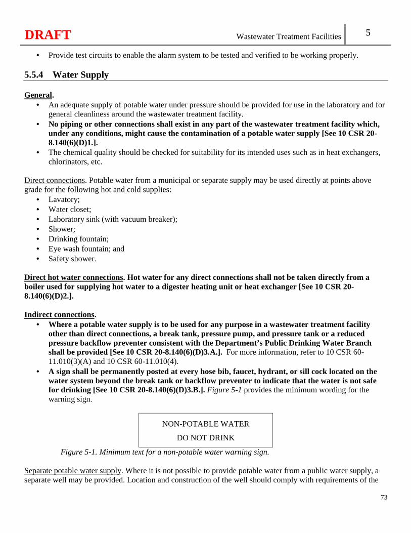
DRAFT Wastewater Treatment Facilities 5
73
• Provide test circuits to enable the alarm system to be tested and verified to be working properly. 5.5.4 Water Supply General.
• An adequate supply of potable water under pressure should be provided for use in the laboratory and for general cleanliness around the wastewater treatment facility.
• No piping or other connections shall exist in any part of the wastewater treatment facility which, under any conditions, might cause the contamination of a potable water supply [See 10 CSR 20-8.140(6)(D)1.].
• The chemical quality should be checked for suitability for its intended uses such as in heat exchangers, chlorinators, etc.
Direct connections. Potable water from a municipal or separate supply may be used directly at points above grade for the following hot and cold supplies:
• Lavatory; • Water closet; • Laboratory sink (with vacuum breaker); • Shower; • Drinking fountain; • Eye wash fountain; and • Safety shower.
Direct hot water connections. Hot water for any direct connections shall not be taken directly from a boiler used for supplying hot water to a digester heating unit or heat exchanger [See 10 CSR 20-8.140(6)(D)2.]. Indirect connections.
• Where a potable water supply is to be used for any purpose in a wastewater treatment facility other than direct connections, a break tank, pressure pump, and pressure tank or a reduced pressure backflow preventer consistent with the Department’s Public Drinking Water Branch shall be provided [See 10 CSR 20-8.140(6)(D)3.A.]. For more information, refer to 10 CSR 60-11.010(3)(A) and 10 CSR 60-11.010(4).
• A sign shall be permanently posted at every hose bib, faucet, hydrant, or sill cock located on the water system beyond the break tank or backflow preventer to indicate that the water is not safe for drinking [See 10 CSR 20-8.140(6)(D)3.B.]. Figure 5-1 provides the minimum wording for the warning sign.
NON-POTABLE WATER
DO NOT DRINK
Figure 5-1. Minimum text for a non-potable water warning sign. Separate potable water supply. Where it is not possible to provide potable water from a public water supply, a separate well may be provided. Location and construction of the well should comply with requirements of the
DRAFT Wastewater Treatment Facilities 5
74
Department’s Public Drinking Water Branch and in subsection 5.5.4, Direct connections, Direct hot water connections, and Indirect connections. Separate non-potable water supply. Where a separate non-potable water supply is to be provided, a break tank will not be necessary, but all system outlets shall be posted with a permanent sign indicating the water is not safe for drinking [See 10 CSR 20-8.140(6)(D)4.]. Refer to subsection 5.5.4, Indirect connections, for more information on the signage. 5.5.5 Sanitary Facilities Toilet, shower, lavatory, and locker facilities should be provided in sufficient numbers and at convenient locations to serve the expected facility personnel. 5.5.6 Floor Slope Design floor surfaces to slope to a point of drainage. 5.5.7 Stairways, Railings, and Walkways Install stairways in lieu of ladders for access to units requiring routine inspection and maintenance, such as digesters, trickling filters, aeration tanks, clarifiers, tertiary filters, etc. Spiral or winding stairs are permitted only for secondary access where dual means of egress are provided. Design stairway slopes between thirty degrees (30°) and forty degrees (40°) from the horizontal to facilitate carrying samples, tools, etc. Each tread and riser should be of uniform dimension in each flight. Design a flight of stairs with more than a twelve foot (12') continuous rise with a platform. Provide a removable chain for openings in railings. Provide hand railings with toe-boards, where appropriate, for open valve box, pit, tank, basin, trench, stairwells, and other hazardous structures where the top of wall is less than forty-two inches (42") above the surrounding ground level. Equip a walkway above an open tank with a raised edge. An overhead pipe should have at least a seven foot (7') clearance, unless the pipe is padded to prevent head injury and has a warning sign. 5.5.8 Protection from the Elements Design all wastewater treatment facilities, except those facilities which operate only seasonally, to ensure effective operation under all weather conditions. Protection from the elements should be given the following consideration:
• Provisions for covering exposed process areas with boards or insulating panels may be sufficient; • The use of heat tapes around scum and solids return piping in addition to covering the tanks; • A sufficient number of electrical outlets;
DRAFT Wastewater Treatment Facilities 5
75
• Tanks which are not completely backfilled on all sides may require additional protective measures during freezing weather; and
• Any such measures taken to protect process units should not present a hazard to facility personnel nor hinder the operation of the wastewater treatment facility.
5.5.9 Flow Measurement A means of flow measurement shall be provided at all wastewater treatment facilities [See 10 CSR 20-8.140(6)(E)]. Location. Provide flow measurement equipment to measure the following flows:
• Influent; • Effluent flow and other flows to be monitored under the provisions of the operating permit; and • Where applicable, other flows such as return activated sludge, waste activated sludge, recirculation, and
recycle for operational control. Facilities.
• Provide indicating, totalizing, and recording flow measurement devices for wastewater treatment facilities with a design average flow of one hundred thousand gallons per day (100,000 gpd) or greater.
• Provide a flume or weir without a secondary measuring device at a minimum for wastewater treatment facilities with a design average flow less than one hundred thousand gallons per day (100,000 gpd). � An elapsed time meter used in conjunction with pumping rate tests may be considered an approvable
alternate to a flume or weir when all of the influent or effluent is pumped by a single influent pump station.
� The design should facilitate the installation of continuous flow recording equipment. Measuring equipment. Size all flow measurement equipment to function effectively over the full range of flows expected. Provide protection against freezing for flow measurement equipment. Hydraulic conditions. Design flow measurement equipment including approach and discharge conduit configuration and critical control elevations to ensure the required hydraulic conditions necessary for accurate measurement are provided. Avoid turbulence, eddy currents, air entrainment, or any other aspect that upsets the normal hydraulic conditions that are necessary for accurate flow measurement. 5.5.10 Sampling Equipment Effluent twenty-four (24) hour composite automatic sampling equipment shall be provided at all mechanical wastewater treatment facilities and at other facilities where necessary under provisions of the operating permit. See 10 CSR 20-7.015, Effluent Regulations [See 10 CSR 20-8.140(6)(F)]. Also, provide twenty-four (24) hour composite automatic sampling equipment for influent sampling when monitored under the provisions of the operating permit. The influent sampling point should be located prior to any process return flows.
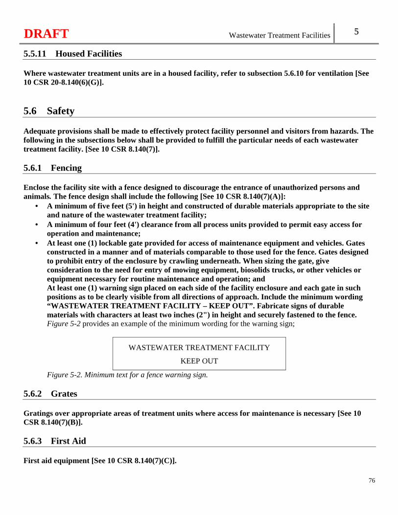
DRAFT Wastewater Treatment Facilities 5
76
5.5.11 Housed Facilities Where wastewater treatment units are in a housed facility, refer to subsection 5.6.10 for ventilation [See 10 CSR 20-8.140(6)(G)].
5.6 Safety Adequate provisions shall be made to effectively protect facility personnel and visitors from hazards. The following in the subsections below shall be provided to fulfill the particular needs of each wastewater treatment facility. [See 10 CSR 8.140(7)]. 5.6.1 Fencing Enclose the facility site with a fence designed to discourage the entrance of unauthorized persons and animals. The fence design shall include the following [See 10 CSR 8.140(7)(A)]:
• A minimum of five feet (5') in height and constructed of durable materials appropriate to the site and nature of the wastewater treatment facility;
• A minimum of four feet (4') clearance from all process units provided to permit easy access for operation and maintenance;
• At least one (1) lockable gate provided for access of maintenance equipment and vehicles. Gates constructed in a manner and of materials comparable to those used for the fence. Gates designed to prohibit entry of the enclosure by crawling underneath. When sizing the gate, give consideration to the need for entry of mowing equipment, biosolids trucks, or other vehicles or equipment necessary for routine maintenance and operation; and At least one (1) warning sign placed on each side of the facility enclosure and each gate in such positions as to be clearly visible from all directions of approach. Include the minimum wording “WASTEWATER TREATMENT FACILITY – KEEP OUT”. Fabrica te signs of durable materials with characters at least two inches (2") in height and securely fastened to the fence. Figure 5-2 provides an example of the minimum wording for the warning sign;
WASTEWATER TREATMENT FACILITY
KEEP OUT
Figure 5-2. Minimum text for a fence warning sign. 5.6.2 Grates Gratings over appropriate areas of treatment units where access for maintenance is necessary [See 10 CSR 8.140(7)(B)]. 5.6.3 First Aid First aid equipment [See 10 CSR 8.140(7)(C)].
DRAFT Wastewater Treatment Facilities 5
77
5.6.4 No Smoking Posted “No Smoking” signs in hazardous areas [See 10 CSR 8.140(7)(D)]. 5.6.5 Personal Protective Equipment Personal protective equipment (PPE) (e.g., self-contained breathing apparatus, goggles, gloves, hard hats, safety harnesses and line, hearing protectors, etc.) [See 10 CSR 8.140(7)(E)]. 5.6.6 Confined Spaces Portable blower and hose sufficient to ventilate accessed confined spaces [See 10 CSR 8.140(7)(F)]. 5.6.7 Portable Lighting Portable lighting equipment complying with NEC requirements [See 10 CSR 8.140(7)(G)]. 5.6.8 Gas Detectors Gas detectors listed and labeled for use in NEC Class I, Division 1, Group D locations [See 10 CSR 8.140(7)(H)]. 5.6.9 Warning Signs Appropriately-placed warning signs for slippery areas, non-potable water fixtures (see subsection 5.5.4), low head clearance areas, open service manholes, hazardous chemical storage areas, flammable fuel storage areas, high noise areas, etc [See 10 CSR 8.140(7)(I)]. 5.6.10 Ventilation Ventilation shall include the following[See 10 CSR 8.140(7)(J)]:
• Isolate all pumping stations and wastewater treatment components installed in a building where other equipment or offices are located from the rest of the building by an air-tight partition, provide separate outside entrances, and provide separate and independent fresh air supply;
• Force fresh air into enclosed screening device areas or open pits more than four feet (4') deep. Also see subsection 4.1.8;
• Dampers. Dampers are not to be used on exhaust or fresh air ducts. Fine screens or other obstructions on exhaust or fresh air ducts should be avoided to prevent clogging;
• Continuous ventilation. Where continuous ventilation is needed (e.g., housed facilities), provide at least twelve (12) complete air changes per hour. Where continuous ventilation would cause excessive heat loss, provide intermittent ventilation of at least thirty (30) complete air changes per hour when facility personnel enter the area. Base air change demands on one hundred percent (100%) fresh air;
• Electrical controls. Mark and conveniently locate switches for operation of ventilation equipment outside of the wet well or building. Interconnect all intermittently operated ventilation equipment
DRAFT Wastewater Treatment Facilities 5
78
with the respective wet well, dry well, or building lighting system Give consideration to automatic controls where intermittent operation is used. The manual lighting/ventilation switch is expected to override the automatic controls. For a two (2) speed ventilation system with automatic switch over where gas detection equipment is installed, increase the ventilation rate automatically in response to the detection of hazardous concentrations of gases or vapors; and
• Fans, heating, and dehumidification. Fabricate the fan wheel from non-sparking material. Provide automatic heating and dehumidification equipment in all dry wells and buildings. Refer to subsection 5.5.2 for electrical controls.
5.6.11 Explosive Areas Explosion-proof electrical equipment, non-sparking tools, gas detectors etc., in work areas where hazardous conditions may exist, such as digester vaults and other locations where potentially explosive atmospheres of flammable gas or vapor with air may accumulate. See subsection 5.5.2 [See 10 CSR 8.140(7)(K)]. 5.6.12 Lockout/Tagout Provisions for local lockout/tagout on stop motor controls and other devices [See 10 CSR 8.140(7)(L)]. 5.6.13 Arc Flash Provisions for an arc flash hazard analysis and determination of the flash protection boundary distance and type of PPE to reduce exposure to major electrical hazards in accordance with NFPA 70E Standard for Electrical Safety in the Workplace (2018 Edition), as approved and published August 21, 2017. This standard is incorporated by reference in this rule, as published by National Fire Protection Association®, 1 Batterymarch Park, Quincy, MA 02169-7471. This rule does not incorporate any subsequent amendments or additions [See 10 CSR 8.140(7)(M)]. 5.6.14 Confined Space Entry Provisions for confined space entry complying with national industry safety standards [See 10 CSR 8.140(7)(N)]. 5.6.15 Adequate Vector Control Provisions for adequate vector control.
5.7 Chemical Handling Many chemicals used in wastewater treatment can be extremely hazardous when not stored, handled, or used properly. Facility personnel should be thoroughly trained and knowledgeable regarding each specific chemical handling, housing, and application.
DRAFT Wastewater Treatment Facilities 5
79
5.7.1 General Containment materials. The materials utilized for storage, piping, valves, pumping, metering, splash guards, etc., shall be specially selected considering the physical and chemical characteristics of each hazardous or corrosive chemical [See 10 CSR 8.140(8)(A)1.]. Secondary containment. Secondary containment is designed to contain any spilled product from the primary containers or precipitation from the operational containment area and secondary containment area for the amount of time needed for proper cleanup and recovery. Secondary containment shall be designed as follows [See 10 CSR 8.140(8)(A)2.]:
• A minimum volume of one hundred twenty-five percent (125%) of the volume of the largest storage container located within the containment area plus the space occupied by any other tanks located within the containment area when not protected from precipitation.
• A minimum volume of one hundred ten percent (110%) of the volume of the largest storage container located within the containment area plus the space occupied by any other tanks located within the containment area when protected from precipitation.
• No discharge outlet or gravity drain through the wall or floor of the containment structure. • Construct the walls and floors of the secondary containment structure of suitable material that is
compatible with the specifications of the product being stored. Liquid polymer. Liquid polymer should be similarly contained as in subsection 5.7.1, Secondary containment to reduce areas with slippery floors, especially to protect travel ways. Non-slip floor surfaces are desirable in polymer-handling areas. Incompatible chemicals. Make provisions to prevent incompatible chemicals (i.e., strong oxidants and reductants) from intermixing during routine treatment operations. Splash guards. All pumps or feeders for hazardous or corrosive chemicals shall have guards which will effectively prevent spray of chemicals into space occupied by facility personnel [See 10 CSR 8.140(8)(A)3.]. The splash guards are in addition to guards to prevent injury from moving or rotating machinery parts. Piping, labeling, and coupling guard locations.
• All piping containing or transporting corrosive or hazardous chemicals shall be identified with labels every ten feet (10') and with at least two (2) labels in each room, closet, or pipe chase [See 10 CSR 8.140(8)(A)4.A.]. Color-coding may also be used, but is not an adequate substitute for labeling. Refer to subsection 5.3.5 for paint color schemes.
• All connections (flanged or other type), except those adjacent to storage or feeder areas, shall have guards which will direct any leakage away from space occupied by facility personnel [See 10 CSR 8.140(8)(A)4.B.]. Pipes containing hazardous or corrosive chemicals should not be located above shoulder level except where continuous drip collection trays and coupling guards will eliminate chemical spray or dripping onto facility personnel.
Alarm system. Facilities shall be provided for automatic shutdown of pumps and sounding of alarms when failure occurs in a pressurized chemical discharge line [See 10 CSR 8.140(8)(A)5.]. Refer to subsection 5.5.3 for alarm systems.

DRAFT Wastewater Treatment Facilities 5
80
Dust. • Dust collection equipment shall be provided to protect facility personnel from dusts injurious to
the lungs or skin and to prevent polymer dust from settling on walkways which become slick when wet [See 10 CSR 8.140(8)(A)6.].
• Provide for proper transfer of dry chemicals from shipping containers to storage bins or hoppers in such a manner to minimize the quantity of dust that may enter the room.
Flexibility. Provide flexibility for several operational adjustments in chemical feed point location, chemical feed rates, and for feeding alternate chemical compounds. 5.7.2 Chemical Housing The following shall be provided to fulfill the particular needs of each chemical housing facility [See 10 CSR 8.140(8)(B)]:
• Provide storage for a minimum of thirty (30) days’ supply, unless local suppliers and conditions indicate that such storage can be reduced without limiting the supply;
• Construct the chemical storage room of fire and corrosion resistant material; • Equip doors with panic hardware. To prevent unauthorized access, doors lock but do not need a
key to exit the locked room using the panic hardware; • Provide chemical storage areas with drains, sumps, finished water plumbing, and the hose bibs
and hoses necessary to clean up spills and to wash equipment; • Construct chemical storage area floors and walls of material that is suitable to the chemicals being
stored and that is capable of being cleaned; • Floor surfaces should be smooth, chemical resistant, slip resistant, and well drained with three
inches per ten feet (3"/10') minimum slope; • Provide adequate lighting; • The lights and electrical equipment comply with the NEC recommendation based on the chemicals
stored. See subsection 5.5.2; • Chemical containers should be stored in a cool, dry, and well-ventilated area; • Design vents from feeders, storage facilities, and equipment exhaust to discharge to the outside
atmosphere above grade and remote from air intakes; • Avoid storing chemical containers in direct sunlight; • Maintain storage temperatures between forty degrees and eighty-six degrees Fahrenheit (40-86
°F);• Humidity control may be necessary when storing dry chemicals; • Design the storage area with designated areas for “full” and “empty” chemical containers; • Provide storage rooms housing flammable chemicals with an automatic sprinkler system designed
for four tenths gallons per minute per square foot (0.4 gpm/ft2) and a minimum duration of twenty (20) minutes;
• To ensure the safety of facility personnel and the wastewater treatment system, store incompatible chemicals separately. Store any two (2) chemicals that can react to form a toxic gas in separate housing facilities;
• Properly design and isolate areas intended for storage and handling of chlorine and sulfur dioxide and other hazardous gases. Refer to sections 10.1 and 10.2 for chlorine and dechlorination;
• Properly design an isolated fireproof storage area and explosion proof electrical outlets, lights, and motors for all powdered activated carbon storage and handling areas in accordance with federal, state, and local requirements;
DRAFT Wastewater Treatment Facilities 5
81
• Vent acid storage tanks to the outside atmosphere, but not through vents in common with day tanks;
• Keep concentrated acid solutions or dry powder in closed, acid-resistant shipping containers or storage units; and
• Do not handle concentrated liquid acids in open vessels, but pump in undiluted form from the original container to the point of treatment or to a covered storage tank.
5.7.3 Chemical Handling Design The design is expected to provide for safe and efficient unloading, storage, transfer, and use of chemicals consistent with appropriate codes considering types of chemicals, compatibility, and the amount of handling necessary. The following shall be provided, where applicable, for the design of chemical handling[See 10 CSR 8.140(8)(C)]:
• Make provisions for measuring quantities of chemicals used for treatment or to prepare feed solutions over the range of design application rates;
• Select storage tanks, piping, and equipment for liquid chemicals specific to the chemicals; • Install all liquid chemical mixing and feed installations on corrosion resistant pedestals; • Provide sufficient capacity of solution storage or day tanks feeding directly for twenty-four (24)-
hour operation at design average flow; • Provide a minimum of two (2) chemical feeders for continuous operability. Provide a standby unit
or combination of units of sufficient capacity to replace the largest unit out-of-service; • Chemical feeders shall [See 10 CSR 20-8.140(8)(C)6.]—
� Design the chemical feed equipment to meet the maximum dosage requirements for the design average flow conditions;
� Able to supply, at all times, the necessary amounts of chemicals at an accurate rate throughout the range of feed;
� Provide proportioning of chemical feed to the rate of flow where the flow rate is not constant; � Design chemical feeders to be readily accessible for servicing, repair and observation; � Protect the entire feeder system against freezing; � Locate the feeder system reasonably adjacent to points of application to minimize length of
feed lines; � Provide for both automatic and manual operation for chemical feed control systems; � Consider automatic chemical dose or residual analyzers and, where provided, include alarms
for critical values and recording charts; � Provide screens and valves on the chemical feed pump suction lines; and � Provide an air break or anti-siphon device where the chemical solution enters the water
stream;• Dry chemical feed system shall [See 10 CSR 20-8.140(8)(C)7.]—
� Equip each dry chemical feeder with a dissolver which is capable of providing a minimum retention period of five (5)-minute at the maximum feed rate;
� Polyelectrolyte feed installations should be equipped with two (2) solution vessels and transfer piping for solution makeup and daily operation;
� Design the makeup tanks with an eductor funnel or other appropriate arrangement for wetting the polymer during the preparation of the stock feed solution;
� Provide adequate mixing by means of a large diameter, low-speed mixer; � Make provisions to measure the dry chemical volumetrically or gravimetrically; and
DRAFT Wastewater Treatment Facilities 5
82
� Completely enclose chemicals and prevent emission of dust; • For phosphorus removal, give consideration to systems including pumps and piping that will feed
either iron or aluminum compounds to provide flexibility; • Provide for uniform strength of solution consistent with the nature of the chemical solution for
solution tank dosing; • Diaphragm or piston type positive displacement type solution feed pumps are not acceptable to
feed chemical slurries; • Provide continuous agitation to maintain slurries in suspension; • Provide a minimum of two (2) flocculation tanks or channels having a combined detention period
of twenty to thirty (20 – 30) minutes. Provide independent controls for each tank or channel; • Insulate pipelines carrying soda ash at concentrations greater than twenty percent (20%) solution
to prevent crystallization; and • Do not store bagged soda ash in a damp or humid place.
5.7.4 Chemical Safety Provide the following in this subsection in addition to the safety provisions in section 5.6: PPE. The following items of PPE shall be available and utilized for all operations or procedures where their use will minimize injury hazard to facility p ersonnel [See 10 CSR 8.140(8)(D)1.]:
• Self-contained breathing apparatus recommended for protection against chlorine and other hazardous fumes;
• Chemical worker’s goggles or other suitable goggles (safety glasses are insufficient); • Face masks or shields for use over goggles; • Dust mask to protect the lungs in dry chemical areas; • Rubber gloves; • Rubber aprons with leg straps; and • Rubber boots (leather and wool clothing should be avoided near caustics).
Eye wash fountains and safety showers. Eye wash fountains and safety showers utilizing potable water shall be provided in the laboratory and on each floor level or work location involving hazardous or corrosive chemical storage, mixing (or slaking), pumping, metering, or transportation unloading. The design of eye wash fountains and safety showers shall include the following [See 10 CSR 8.140(8)(D)2.]:
• Supply eye wash fountains with water of moderate temperature, fifty degrees to ninety degrees Fahrenheit (50° – 90°F), suitable to provide fifteen to thirty (15 – 30) minutes of continuous irrigation of the eyes;
• Supply emergency showers capable of discharging twenty gallons per minute (20 gpm) of water of moderate temperature, fifty degrees to ninety degrees Fahrenheit (50° – 90°F), and at pressures of thirty to fifty pounds per square inch (30 – 50 psi);
• Locate eye wash fountains and emergency showers no more than twenty-five feet (25') from points of hazardous chemical exposure; and
• Eye wash fountains and showers are to be fully operable during all weather conditions. Warning signs. Warning signs requiring use of goggles shall be located near chemical stations, pumps, and other points of frequent hazard See 10 CSR 8.140(8)(D)3.].
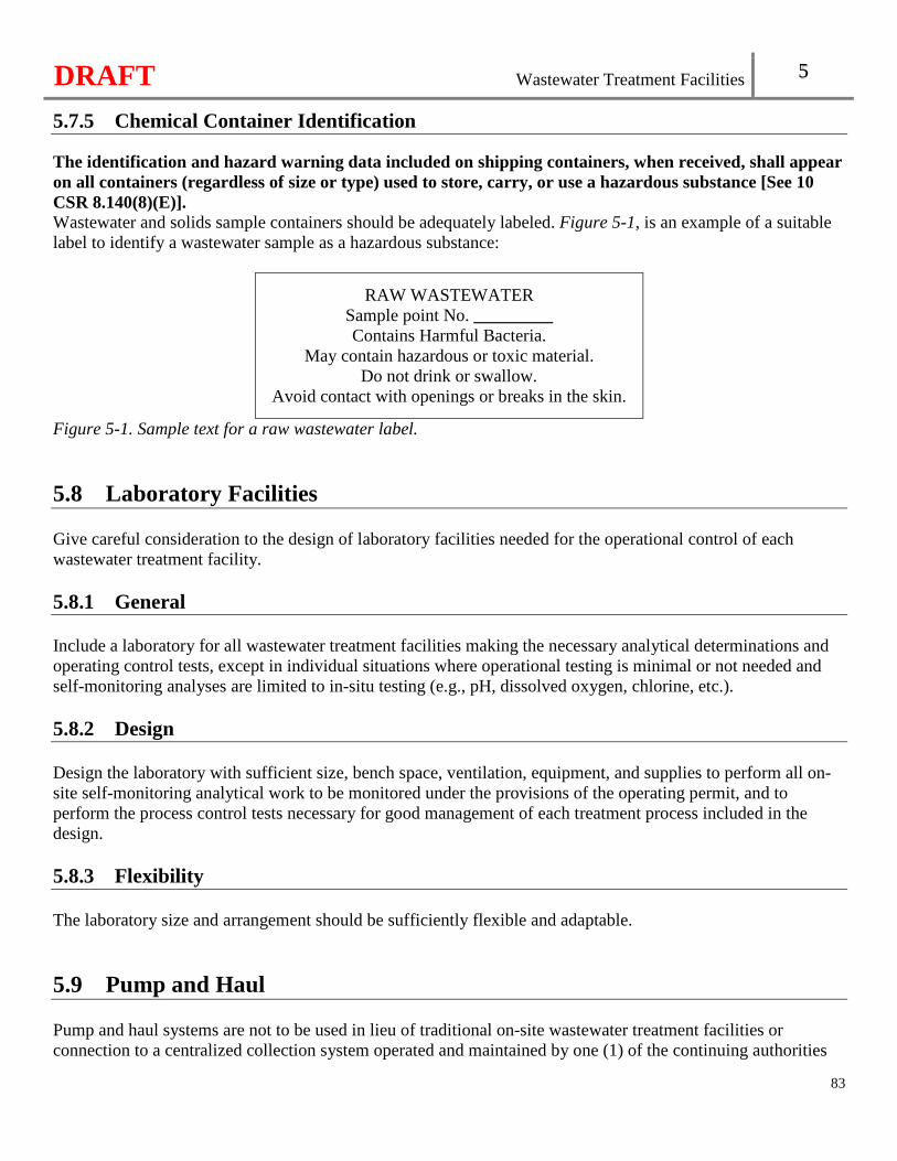
DRAFT Wastewater Treatment Facilities 5
83
5.7.5 Chemical Container Identification The identification and hazard warning data included on shipping containers, when received, shall appear on all containers (regardless of size or type) used to store, carry, or use a hazardous substance [See 10 CSR 8.140(8)(E)]. Wastewater and solids sample containers should be adequately labeled. Figure 5-1, is an example of a suitable label to identify a wastewater sample as a hazardous substance:
RAW WASTEWATER Sample point No. _________ Contains Harmful Bacteria.
May contain hazardous or toxic material. Do not drink or swallow.
Avoid contact with openings or breaks in the skin.
Figure 5-1. Sample text for a raw wastewater label.
5.8 Laboratory Facilities Give careful consideration to the design of laboratory facilities needed for the operational control of each wastewater treatment facility. 5.8.1 General Include a laboratory for all wastewater treatment facilities making the necessary analytical determinations and operating control tests, except in individual situations where operational testing is minimal or not needed and self-monitoring analyses are limited to in-situ testing (e.g., pH, dissolved oxygen, chlorine, etc.). 5.8.2 Design Design the laboratory with sufficient size, bench space, ventilation, equipment, and supplies to perform all on-site self-monitoring analytical work to be monitored under the provisions of the operating permit, and to perform the process control tests necessary for good management of each treatment process included in the design. 5.8.3 Flexibility The laboratory size and arrangement should be sufficiently flexible and adaptable.
5.9 Pump and Haul Pump and haul systems are not to be used in lieu of traditional on-site wastewater treatment facilities or connection to a centralized collection system operated and maintained by one (1) of the continuing authorities
DRAFT Wastewater Treatment Facilities 5
84
listed in 10 CSR 20-6.010(3)(B). The Department will review and approve pump and haul systems on a case-by-case basis. Pump and haul systems are not a form of wastewater treatment. Therefore, prevention of the discharge of raw wastewater to any waters of the state and to protect public health is necessary. 5.9.1 General Accessibility. Conform to Chapter 5, Access Road [See 10 CSR 20-8.140(9)(A)1.]. Security. Provide access hatches and electrical control panels with locks. Refer to subsection 5.6.1 for fencing [See 10 CSR 20-8.140(9)(A)2.]. Buoyancy. Where high groundwater conditions are anticipated, consider buoyancy of the piping and wastewater structures and, if necessary, make adequate provisions for buoyancy protection. Protection of water supplies. Provide the separation and crossing of water supplies in accordance with Chapter 5, Minimum Separation Distances and subsection 2.8 [See 10 CSR 20-8.140(9)(A)3.]. 5.9.2 Septic Tank Design Conform to section 9.1 for septic tank design. In addition, the septic tank design shall provide a minimum of thirty (30) days detention time [See 10 CSR 20-8.140(9)(B)]. 5.9.3 Earthen Basin Design Refer to Chapter 11 for earthen basin design [See 10 CSR 20-8.140(9)(C)]. 5.9.4 Controls Water level control sensing device should be located to prevent undue affects from turbulent flows entering the septic tank or earthen basin. Water level controls should be accessible without entering the septic tank or earthen basin. 5.9.5 Alarm System The alarm shall be activated in cases of high water levels. Refer to subsection 5.5.3 for alarm systems [See 10 CSR 8.140(9)(D)].

DRAFT
85
DRAFT Preliminary Treatment 6
Chapter 6: Preliminary Treatment
86
Preliminary Treatment Device. All wastewater treatment facilities must have a screening device, comminutor, or septic tank for the purpose of removing debris and nuisance materials from the influent wastewater [See 10 CSR 8.150(2)]. Fats, Oils, and Grease. Proper wastewater treatment facility design includes provisions for removing fats, oils, and grease (FOG) from the wastewater. Electrical. Refer to subsection 5.5.2.
6.1 Screening Devices 6.1.1 General Design.
• Flow distribution. Design entrance channels to provide equal and uniform distribution of flow to the screening devices.
• Flow measurement. Select flow measurement devices for reliability and accuracy. Consider the effect of changes in backwater elevation due to intermittent cleaning of screening devices in locations of flow measurement equipment. See subsection 5.5.9 regarding flow measurement devices.
• Freeze protection. Mechanically cleaned screening devices and screening storage areas shall be protected from freezing [See 10 CSR 8.150(3)(A)1.].
• Corrosion resistance. Select screening devices and related structures designed to resist the effects of a corrosive environment, including long-term exposure to hydrogen sulfide.
• Unit Isolation. Provisions shall be made for isolating or removing screening devices from their location for servicing [See 10 CSR 20-8.150(3)(A)2.]. See subsection 5.3.2 unit isolation for more information.
Screenings removal and disposal.
• Provide a convenient and adequate means for removing screenings. When designing a screening device with the working surface of the screen located in pits more than four feet (4') deep, provide mechanical hoisting or lifting equipment capable of lifting the screenings to ground level without facility personnel entry.
• Provide equipment for handling, storage, and disposal of screenings in a sanitary manner with provisions to minimize vector attraction. It is unacceptable to return grindings and screenings to the wastewater flow.
• Where manually cleaned screening devices are used, include an accessible platform from which facility personnel may rake screenings easily and safely. Provide suitable drainage facilities for both the platform and the screenings storage area.
• Provide impervious, non-slip, working surfaces with adequate drainage for screening handling areas. • Design areas related to the transfer and transportation of screenings in a manner that protects against the
loss of these materials. • Dispose of screenings at a frequency that prevents creation of a nuisance. Odor control facilities may
also be warranted.
DRAFT Preliminary Treatment 6
87
Servicing. • When hosing equipment is used, refer to subsection 5.5.4 for wastewater treatment facility water
supplies. Access. Consider providing stairway access for screening devices located in pits more than four feet (4') deep. Access ladders are acceptable for pits less than four feet (4') deep, in lieu of stairways. Ventilation. Refer to subsection 5.6.10. Safety.
• Railings and gratings. � Manually cleaned screen channels shall be protected by guard railings and deck gratings, with
adequate provisions for removal or opening to facilitate raking [See 10 CSR 8.150(3)(A)3.A.(I)].
� Mechanically cleaned screen channels shall be protected by guard railings and deck gratings. Give consideration to temporary access arrangements to facilitate maintenance and repair [See 10 CSR 8.150(3)(A)3.A.(II)].
� Also refer to subsection 5.5.7 stairways, railings, and walkways for more information. • Mechanical devices.
� Mechanical screening equipment shall have adequate removal enclosures to protect facility personnel against accidental contact with moving parts and to prevent dripping in multi-level installations [See 10 CSR 8.150(3)(A)3.B.(I)].
� A positive means of locking out each mechanical device shall be provided [See 10 CSR 8.150(3)(A)3.B.(II)].
� An emergency stop button with an automatic reverse function shall be located in close proximity to the mechanical device [See 10 CSR 8.150(3)(A)3.B.(III)].
• Lighting. Provide suitable lighting in all work and access areas. Electrical equipment and control systems.
• Timing devices. For all mechanical units that are operated by timing devices, provide auxiliary controls that will set the cleaning mechanism in operation at a preset high water elevation. If the cleaning mechanism fails to lower the high water, a warning should be signaled.
• Electrical equipment, fixtures, and controls. Refer to Chapter 6, Electrical for screening areas. • Manual override. Provide a manual override for all automatic controls.
6.1.2 Coarse Screens Coarse screens provide protection for downstream pumps and other equipment. Bar spacing.
• Manually cleaned. Clear openings between bars should be two inches (2") or less for manually cleaned screens.
• Mechanically cleaned. Maximum clear openings should be one and three-fourths inches (1 3/4") Slope. Manually cleaned screens should be placed on a slope of thirty to forty-five degrees (30°–45°) from the horizontal.
DRAFT Preliminary Treatment 6
88
Velocities. At design average flow conditions, approach velocities of no less than one and one-quarter feet per second (1.25 ft/s) prevents settling; and no greater than three feet per second (3.0 ft/s) to prevent forcing material through the openings. Channels.
• Manually cleaned screen. Provide a single channel for each manually cleaned screen. • Mechanically cleaned screen. For facilities with mechanically cleaned screens, provide dual channels
and equip them with the necessary gates to isolate flow from any screening unit. • Dewatering. Make provisions to facilitate dewatering each channel. • Channel design. Design the shape of the channel preceding and following the screen to eliminate
stranding and settling of solids. Auxiliary screens.
• Where a single mechanically cleaned screen is used, provide an auxiliary manually cleaned screen. Consider provisions for future installation of a second mechanically cleaned screen.
• Where two (2) or more mechanically cleaned screens are used, the design shall provide for taking any unit out-of-service without sacrificing the capability to handle the design peak instantaneous flow [See 10 CSR 8.150(3)(B)].
Invert. The screen channel invert should be three to six inches (3" – 6") below the invert of the incoming sewer. To prevent jetting action, provide the adequate length and geometry of the channel to reestablish the hydraulic flow pattern following the drop in elevation. 6.1.3 Fine Screens General.
• Fine screens, as discussed in this subsection, have clear openings of one sixteenth to one quarter inch (1/16" – 1/4"). The amount of material removed by fine screens is dependent on the waste stream being treated and screen opening size.
• Fine screens should not be considered equivalent to primary settling. However, fine screens may be used in lieu of primary settling where subsequent treatment units are designed on the basis of anticipated screen performance. Selection of screen capacity should consider flow restriction due to retained solids, adhesive materials, frequency of cleaning, and extent of cleaning. Where fine screens are used, consider additional provisions for the removal of FOG.
• Provide hosing equipment to facilitate cleaning. Refer to subsection 5.5.4 for wastewater treatment facility water supplies.
Design.
• When used, a minimum of two (2) fine screens shall be provided; with each unit being capable of independent operation. Capacity shall be provided to treat design peak instantaneous flow with the largest unit out-of-service [See 10 CSR 8.150(3)(C)].
• Fine screens should be preceded by a coarse screening device. • Equip moving or rotating fine screens with a cleaning device, such as water jets or wiper blades. • Automatically convey the screenings to a storage area or processing unit with provisions to minimize
vector attraction. • Meet the manufacturer’s recommendations with respect to velocity and head loss through the fine
DRAFT Preliminary Treatment 6
89
screen. Organic removal credit. Any BOD5 and suspended solids reduction percentage claimed for a fine screen are to be developed through a pilot study conducted on actual full-scale operation of the proposed fine screen at the design maximum day flow and design maximum day organic loadings. Pilot testing for an extended time is preferred to cover seasonal operational variations. Refer to section 1.4 for pilot testing.
• The BOD5 reduction percentage claimed must not exceed thirty-five percent (35%). • A wastewater treatment facility claiming an organic reduction credit should include a minimum of two
(2) fine screen units so that any organic reduction claimed will be met with the largest fine screen out-of-service.
6.1.4 Microscreens Wastewater treatment facilities proposing microscreens for preliminary treatment are subject to evaluations on a case-by-case basis. Refer to section 12.4.
Microscreens have clear openings of less than one millimeter (1 mm). Locate microscreens downstream of grit removal equipment and protect them with a coarse screening device at a minimum.
6.2 Comminutors Comminutors cut and shred stringy materials and coarse solids into smaller sizes approximately one quarter to three quarter inches (0.25" - 0.75"). 6.2.1 General Provisions for location and safety shall be in accordance with screening devices, subsection 6.1.2 [See 10 CSR 8.150(4)].
6.2.2 When Used Comminutors may be used in lieu of screening devices to protect equipment where stringy substance accumulation on downstream equipment will not be a substantial problem.
6.2.3 Design Considerations Location.
• Locate comminutors downstream of grit removal equipment and protect with a coarse screening device. • When a comminutor is not preceded by grit removal equipment, protect it with a six inch (6") deep
gravel trap.
DRAFT Preliminary Treatment 6
90
Size. Design the comminutor capacity to adequately handle the design peak hourly flow. Installation.
• At a minimum, provide an auxiliary coarse, manually cleaned screened channel. The use of the auxiliary screened channel should be automatic for all comminutor failures and at depths of flow exceeding the design capacity for the comminutor.
• Provide gates in accordance with subsection 6.1.2, Channels and subsection 6.1.2, Auxiliary screens. Servicing. Make provisions to facilitate servicing units in place and to remove units from their location for servicing. Electrical controls and motors. Refer to Chapter 6, Electrical for electrical equipment in comminutor chambers. Protect motors against accidental submergence.
6.3 Grit Removal Facilities 6.3.1 General Wastewater treatment facilities using membrane bioreactors for secondary treatment, anaerobic digestion, and facilities receiving wastewater from either combined sewers or from sewer systems receiving substantial amounts of grit must have grit removal facilities [See 10 CSR 8.150(5)]. Provide grit removal facilities for all mechanical wastewater treatment facilities. When a wastewater treatment facility serving a separate sewer system is designed without grit removal facilities, consider including provisions for future installation. Give consideration to possible damaging effects on pumps, comminutors, and other equipment, and the need for additional storage capacity in treatment units where grit is likely to accumulate.
6.3.2 Location General. Locate grit removal facilities ahead of pumps and comminuting devices. Place coarse screening devices ahead of grit removal facilities. Housed facilities.
• Ventilation. Refer to subsection 5.6.10. Odor control facilities may also be warranted. • Access. Provide adequate stairway access to above or below grade facilities. Refer to subsection 6.1.1,
Access. • Electrical. Refer to Chapter 6, Electrical for enclosed grit removal areas. Provide explosion proof gas
detectors in accordance with subsection 5.6.8. Outside facilities. Protect grit removal facilities located outside from freezing.
6.3.3 Size Size grit removal facilities with fixed capacity to treat the design peak hourly flow.
DRAFT Preliminary Treatment 6
91
6.3.4 Number of Units Wastewater treatment facilities treating wastes from combined sewers should have at least two (2) mechanically cleaned grit removal units, with provisions for unit isolation. A single manually cleaned or mechanically cleaned grit chamber with provisions for unit isolation is acceptable for wastewater treatment facilities with a design average flow of less than one (1) million gallons per day serving separate sanitary sewer systems. Wastewater treatment facilities with a design average flow of one (1) million gallons per day or greater serving separate sanitary sewers should have at least one (1) mechanically cleaned unit with provisions for unit isolation.
6.3.5 Grit Chamber Types For facilities other than channel-type, adequate and flexible controls for velocity and/or air supply devices, grit collection, and removal equipment.
Channel-type grit chambers.
• Design the channel for a velocity range of eight-tenths to one and three-tenths (0.8 – 1.3) feet per second at design average flow.
• Minimize turbulence and provide uniform velocity across the channel. • Size the channel to accommodate the grit removal equipment capacity and grit storage.
Aerated grit chambers.
• Design aerated grit chambers to have adjustable air rates in the range of three to eight (3 – 8) cubic feet per minute per foot of tank length.
• Provide a detention time in the tank of three to five (3 – 5) minutes at design peak hourly flows. • Locate the grit hopper under an air diffuser.
Mechanical grit chambers.
• Design a maximum velocity of one (1) foot per second at design average flow. • Include a grit hopper in each channel with a grit removal mechanism. • Include inlet baffles to prevent short-circuiting. • Provide grit removal by one (1) of the following mechanisms:
� Reciprocating rake; � Screw conveyor; or � Air lift pump.
Cyclonic grit chambers.
• Design cyclonic grit chambers to prevent inlet-to-outlet short-circuiting. • Include an adjustable apex with a quick disconnect assembly to remove any oversized object. • Provide a minimum detention time one (1) minute at the design average flow. • Design the flow velocity range to one to two (1 - 2) feet per second at design average flow. • Install screening devices upstream of a cyclonic grit chamber.
DRAFT Preliminary Treatment 6
92
Vortex grit chamber. • Design inlet channels to include a straight length in order to deliver smooth flow into the vortex grit
chamber. Design the length of the inlet channel to be at least seven (7) times the width or fifteen feet (15'), whichever is greater.
• Provide a minimum detention time of thirty (30) seconds at the design average flow. • Design a minimum inlet velocity of two (2) feet per second at peak flow. • Provide a propeller with a variable speed drive to operate the unit based upon the flow. • Maintain a constant elevation in the outlet channel. • Provide air or water scour to loosen compacted grit and facilitate the grit lifting and removal from the
chamber.
6.3.6 Design Factors General. Design the effectiveness of a grit removal system commensurate with the requirements of the subsequent process units. Detention. Base the detention period on the size of particle to be removed. Aerated grit removal. All aerated grit removal facilities should be provided with adequate control devices to regulate air supply and agitation. Pumped grit removal. Select pumps specifically designed to handle grit.
Grit washing. Determine the need for grit washing based on the method of grit handling and final disposal. Grit piping. Install cleanouts on grit piping to facilitate maintenance. Quick removable fittings should be installed at all changes in alignment on grit piping. Dewatering. Make provisions for isolating and dewatering each unit. Provide for complete draining and cleaning by means of a sloped bottom equipped with a drain sump. Water. Provide an adequate supply of water under pressure for cleanup. Refer to subsection 5.5.4 for wastewater treatment facility water supplies.
6.3.7 Grit Handling and Disposal Provide for grit handling and disposal in accordance with subsection 6.1.1, Screenings removal and disposal.
6.3.8 Safety Refer to subsection 6.1.1, Safety.
6.4 Preaeration Preaeration of wastewater can reduce septicity, separate grease, promote uniform distribution of solids during
DRAFT Preliminary Treatment 6
93
settling, or function as an odor control measure.
6.4.1 Servicing Design preaeration unit operations so that removal from service will not interfere with normal downstream operation of the remainder of the treatment facility.
6.4.2 Inlet and Outlet Design inlet and outlet devices to ensure proper distribution and help prevent solids deposition, while minimizing any hydraulic short circuiting effects. 6.4.3 Aeration The aeration equipment should be capable of obtaining both adequate mixing and self-cleaning velocities within the basin.
6.5 Diurnal Flow Equalization 6.5.1 General Consider the use of diurnal flow equalization for the following:
• Where significant variations in organic and hydraulic loadings are expected, where the design maximum day to the design average is greater than three to one (3:1). See also subsection 5.2.5, Flow equalization;
• At all wastewater treatment facility receiving significant industrial waste. A diurnal flow equalization basin could isolate a shock loading from an industrial facility prior to adverse impacts on the wastewater treatment facility’s processes and effluent quality;
• At all wastewater treatment facilities utilizing a wet weather flow equalization basin; or • Ahead of sequencing batch reactors or other mechanical batch discharging treatment facilities. See also
section 9.6. 6.5.2 Location Locate diurnal flow equalization basins downstream of preliminary treatment components such as screening devices, comminutors, and grit removal facilities.
6.5.3 Type Diurnal flow equalization can be provided by using separate basins or on-line treatment units, such as aeration tanks. Diurnal flow equalization basins may be designed as either in-line or side-line units. When a wastewater treatment facility has an actual flow of fifty percent (50%) or less of the design average flow, unused treatment units, such as settling or aeration tanks, may be utilized as diurnal flow equalization
DRAFT Preliminary Treatment 6
94
basins.
6.5.4 Size Size diurnal flow equalization basin capacity to effectively reduce expected flow and load variations to the extent deemed to be economically advantageous. With a diurnal flow pattern, the volume to achieve the desired degree of equalization can be determined from a cumulative flow plot over the representative twenty-four (24)-hour period.
6.5.5 Operation Mixing and aeration. To facilitate operations:
• Provide aeration or mechanical equipment to maintain adequate mixing; • Provide corner fillets and hopper bottoms with draw-offs to alleviate the accumulation of sludge and
grit; • Maintain a minimum of one milligram per liter (1.0 mg/l) of dissolved oxygen in the mixed basin
contents at all times; • When used, supply a minimum of one and one quarter (1.25) cubic feet per minute of air per one
thousand (1,000) gallons of storage capacity; and • Isolate the air supply from other treatment facility aeration requirements to facilitate process aeration
control, although process air supply equipment may be utilized as a source of standby aeration. Controls. Equip inlets and outlets for all basin compartments with accessible external valves, stop plates, weirs, or other devices to permit flow control and the removal of an individual unit from service. Provide a means to measure and indicate liquid levels and flow rates leaving the basin. For pumped flow to a diurnal flow equalization basin, control the effluent from the basin by means of a flow-regulating device capable of maintaining a flow rate that allows downstream process units to operate as designed. For pumped flow from a diurnal flow equalization basin, utilize a variable-speed pump or multiple pumps to deliver a constant flow to downstream treatment units.
6.5.6 Construction Materials See section 11.3 when earthen basin construction is selected.
6.5.7 Number of Basins Diurnal flow equalization basins with a storage capacity exceeding twenty thousand (20,000) gallons should be constructed as compartmentalized or as multiple basins.
6.5.8 Electrical Refer to Chapter 6, Electrical for housed diurnal flow equalization basins.
DRAFT Preliminary Treatment 6
95
6.5.9 Access Provide suitable access to facilitate cleaning and maintenance of equipment.
6.6 Wet Weather Flow Equalization 6.6.1 General Consider the use of wet weather flow equalization for the following:
• Where significant variations in organic and hydraulic loadings are anticipated; • Where the wet weather flow is greater than the dry-weather design peaking factor of the wastewater
treatment facility serving separate sanitary sewer systems. Refer to subsection 1.1.2, Equation 1-1; • At all wastewater treatment facilities treating wastes from combined sewers; or • At all seasonal wastewater treatment facilities.
6.6.2 Basin Type For gravity inlet systems, provide flow splitting or automated flow diversion devices to divert excess flows to the basin(s). For pumped systems, install control valves or use dedicated pumps to handle and divert wet weather flow to the basin. Depending on the elevation of the basin, it may be possible to return the flow to the head of the wastewater treatment facility by gravity. If not, include in the design a dedicated pump return system.
6.6.3 Design The design of basins entails a thorough evaluation of wet weather flow patterns and volumes. Items to be considered are basin geometry, construction materials, storage capacity, and operational controls. 6.6.4 Construction Materials See section 11.3 when earthen basin construction is selected.
6.6.5 Basin Layout For storage of five (5) million gallons or more, design basins to have a minimum of two (2) compartments designed to operate in series. Divert all flow to a basin where solids can settle and, at a predetermined elevation, overflow to additional basins. A single basin equipped with an impervious liner is acceptable where the storage capacity is less than five (5) million gallons. If utilizing an existing earthen basin for flow equalization or for storage, barrel test the seal to verify the seal still meets the requirements of subsection 11.3.3.
DRAFT Preliminary Treatment 6
96
6.6.6 Storage Capacity Design minimum storage to contain the anticipated excess flow during the largest seven (7)-day wet weather period in ten (10) years, with the capability to be emptied in a timely manner. Use actual flow data, based on no less than one (1) year of influent flow data, to develop flow balance or mass diagrams for determining basin capacity. Base the frequency and duration of storms on field data and weather service records. 6.6.7 Pumps and Flow Control Methods Return excess flows retained by a wet weather flow equalization basin to the head of the wastewater treatment facility in a timely manner during off-peak periods. Controls are necessary to regulate flow to the wet weather flow equalization basin and return flow.
Provide adequate controls with measuring devices to divert all flow in excess of the wastewater treatment facility’s hydraulic capacity to the basin. Make provisions and controls to return the basin contents to the head of the wastewater treatment facility after the wet weather event has passed and influent flow returned to normal. Return flow may be manual or automatic, but include sufficient flow measurement and instrumentation devices to determine the actual return flow to the head of the wastewater treatment facility. Where basin return flow is automatic, design the control equipment to limit the combination of influent flow plus the basin return flow to the hydraulic capacity of the wastewater treatment facility.
6.7 Grease Interceptors 6.7.1 Where Applicable Grease interceptors shall be provided on kitchen drain lines from institutions, hospitals, hotels, restaurants, schools, bars, cafeterias, clubs, and other establishments from which relatively large amounts of grease may be discharged to a wastewater treatment facility owned by the grease producing entity [See 10 CSR 8.150(6)(A)].
6.7.2 Waste Streams Design grease interceptors to receive only the waste streams from grease-producing fixtures. Sanitary waste streams, garbage grinder waste streams, and other waste streams which do not include grease should be excluded from passing through the grease interceptors.
6.7.3 Size Design grease interceptors with a minimum volume of at least one hundred twenty-five (125) gallons or the calculated capacity from Equation 6-1, or local requirement whichever is highest. Provide twenty-five percent
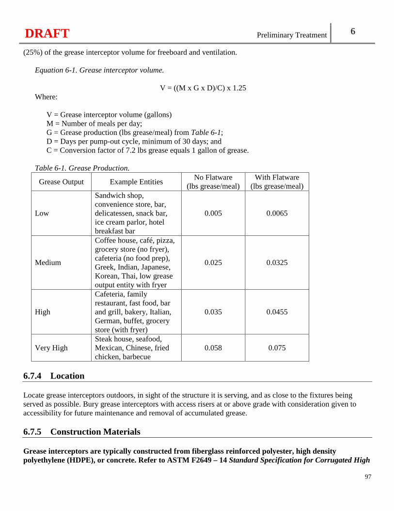
DRAFT Preliminary Treatment 6
97
(25%) of the grease interceptor volume for freeboard and ventilation.
Equation 6-1. Grease interceptor volume.
V = ((M x G x D)/C) x 1.25 Where:
V = Grease interceptor volume (gallons) M = Number of meals per day; G = Grease production (lbs grease/meal) from Table 6-1; D = Days per pump-out cycle, minimum of 30 days; and C = Conversion factor of 7.2 lbs grease equals 1 gallon of grease.
Table 6-1. Grease Production.
Grease Output Example Entities No Flatware
(lbs grease/meal) With Flatware
(lbs grease/meal)
Low
Sandwich shop, convenience store, bar, delicatessen, snack bar, ice cream parlor, hotel breakfast bar
0.005 0.0065
Medium
Coffee house, café, pizza, grocery store (no fryer), cafeteria (no food prep), Greek, Indian, Japanese, Korean, Thai, low grease output entity with fryer
0.025 0.0325
High
Cafeteria, family restaurant, fast food, bar and grill, bakery, Italian, German, buffet, grocery store (with fryer)
0.035 0.0455
Very High Steak house, seafood, Mexican, Chinese, fried chicken, barbecue
0.058 0.075
6.7.4 Location Locate grease interceptors outdoors, in sight of the structure it is serving, and as close to the fixtures being served as possible. Bury grease interceptors with access risers at or above grade with consideration given to accessibility for future maintenance and removal of accumulated grease.
6.7.5 Construction Materials Grease interceptors are typically constructed from fiberglass reinforced polyester, high density polyethylene (HDPE), or concrete. Refer to ASTM F2649 – 14 Standard Specification for Corrugated High
DRAFT Preliminary Treatment 6
98
Density Polyethylene (HDPE) Grease Interceptor Tanks, as approved and published September 1, 2014, for corrugated HDPE grease interceptors and ASTM C1613 – 17 Standard Specification for Precast Concrete Grease Interceptor Tanks, as approved and published September 1, 2017, for precast concrete grease interceptors. These standards are incorporated by reference in this rule, as published by ASTM International, 100 Barr Harbor Drive, P.O. Box C700, West Conshohocken, PA 19428-2959. This rule does not incorporate any subsequent amendments or additions [See 10 CSR 20-8.150(6)(B)]. All pipes and appurtenances within a grease interceptor are to be corrosion resistant. For metal components, provide austenitic stainless steel of type 316 or 304 at a minimum. Nylon is degraded by hydrogen sulfide and is not acceptable. Avoid contact between dissimilar metals or make other provisions to minimize galvanic action.
6.7.6 Watertight Provide watertight grease interceptors. 6.7.7 Access Provide a minimum access diameter of twenty-four inches (24") for access to all chambers of the grease interceptor. Provide bolt-down cover assemblies or locked covers.
6.7.8 Baffles Design grease interceptors with baffles.
6.7.9 Corrosion Protection Provide corrosion protection on the interior of the grease interceptor. All pipes within a grease interceptor are to be corrosion resistant.
6.7.10 Inlet and Outlet Design the inlet to minimize turbulence and to enter below the normal water level. Design the outlet to draw from near the bottom of the grease interceptor, to remove as much FOG as possible.
6.7.11 Cleanouts Install a cleanout on the influent and discharge piping of the grease interceptor.
6.8 Septage Septage is normally considered treatable at a wastewater treatment facility. However, unless proper planning and design is provided, septage may represent a shock loading or have other adverse impacts on the facility’s
DRAFT Preliminary Treatment 6
99
processes and effluent quality. Septage usually is quite high in organics, grease, scum, grit, solids, and other extraneous debris. 6.7.1 General Collect information regarding the characteristics of the local septage to be received for design of septage receiving and treatment systems. The characteristics of septage often vary widely from load to load depending on the source.
6.7.2 Design Include the following elements for the design of the septage receiving station at the wastewater treatment facility:
• A hard surface haul truck unloading ramp sloped to a drain to allow ready cleaning of any spillage and washing of the haul tank, connector hoses, and fittings. Design the ramp to drain to treatment facility, but exclude excessive stormwater;
• A flexible hose fitting with easy connect coupling to provide for direct connection from the haul truck outlet to minimize spillage and help control odors;
• Washdown water with ample pressure, hose, and spray nozzle for convenient cleaning of the septage receiving station and haul trucks. Refer to subsection 5.5.4 for wastewater treatment facility water supplies;
• An adequate off-line septage receiving tank designed to provide complete draining and cleaning by means of a sloped bottom equipped with a drain sump. Give consideration to adequate mixing for testing, uniformity of septage strength, chemical addition (if necessary), for treatability, and odor control. Provide the capability to collect a representative sample of any truck load of waste accepted for discharge at the facility. Facility personnel are to have authority to prevent and stop any disposal that is likely to cause an effluent violation;
• Screening, grit, and grease removal of the septage as appropriate to protect the treatment units; • Pumps for handling the variabilities of septage. Select nonclogging pumps capable of passing three (3)-
inch diameter solids; • Valving and piping for operational flexibility to allow the control of the flow rate and point of septage
discharge to the facility; • Safety features to protect the facility personnel. Refer to section 5.6; and • Laboratory and staffing capability to determine the septage strength and toxicity to the treatment
processes and provisions for operation reports to include the wastewater treatment facility load attributed to septage. Refer to section 5.8.
6.9 Leachate 6.9.1 General Collect data of the leachate to be received for design of the wastewater treatment facility. Leachate usually is quite high in organics, nutrients, and metals.
DRAFT Preliminary Treatment 6
100
Leachate shall not be accepted by wastewater treatment facilities with subsurface soil dispersal systems [See 10 CSR 8.150(7)]. Lagoon facilities proposing acceptance of leachate are subject to review on a case-by-case basis. Due to the low frequency of solids removal from the lagoon, heavy metals and other toxic organics may accumulate making final solids disposal or reuse difficult.
6.9.2 Design Refer to subsection 6.8.2.

DRAFT
101
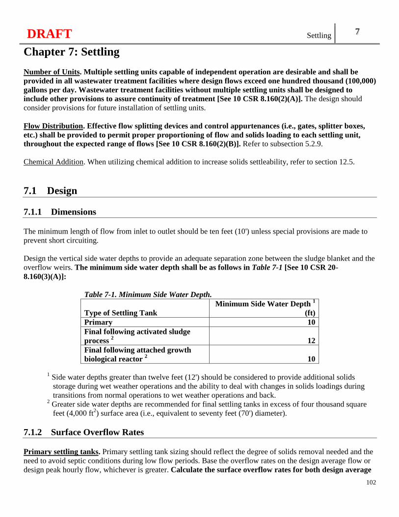
DRAFT Settling 7
Chapter 7: Settling
102
Number of Units. Multiple settling units capable of independent operation are desirable and shall be provided in all wastewater treatment facilities where design flows exceed one hundred thousand (100,000) gallons per day. Wastewater treatment facilities without multiple settling units shall be designed to include other provisions to assure continuity of treatment [See 10 CSR 8.160(2)(A)]. The design should consider provisions for future installation of settling units. Flow Distribution. Effective flow splitting devices and control appurtenances (i.e., gates, splitter boxes, etc.) shall be provided to permit proper proportioning of flow and solids loading to each settling unit, throughout the expected range of flows [See 10 CSR 8.160(2)(B)]. Refer to subsection 5.2.9. Chemical Addition. When utilizing chemical addition to increase solids settleability, refer to section 12.5.
7.1 Design 7.1.1 Dimensions The minimum length of flow from inlet to outlet should be ten feet (10') unless special provisions are made to prevent short circuiting. Design the vertical side water depths to provide an adequate separation zone between the sludge blanket and the overflow weirs. The minimum side water depth shall be as follows in Table 7-1 [See 10 CSR 20-8.160(3)(A)]:
Table 7-1. Minimum Side Water Depth.
Type of Settling Tank Minimum Side Water Depth 1
(ft) Primary 10 Final following activated sludge process 2 12 Final following attached growth biological reactor 2 10
1 Side water depths greater than twelve feet (12') should be considered to provide additional solids
storage during wet weather operations and the ability to deal with changes in solids loadings during transitions from normal operations to wet weather operations and back.
2 Greater side water depths are recommended for final settling tanks in excess of four thousand square feet (4,000 ft2) surface area (i.e., equivalent to seventy feet (70') diameter).
7.1.2 Surface Overflow Rates Primary settling tanks. Primary settling tank sizing should reflect the degree of solids removal needed and the need to avoid septic conditions during low flow periods. Base the overflow rates on the design average flow or design peak hourly flow, whichever is greater. Calculate the surface overflow rates for both design average
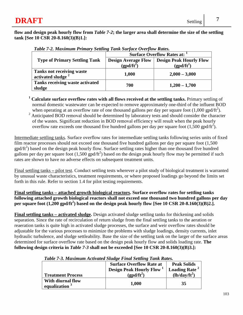
DRAFT Settling 7
103
flow and design peak hourly flow from Table 7-2; the larger area shall determine the size of the settling tank [See 10 CSR 20-8.160(3)(B)1.]:
Table 7-2. Maximum Primary Settling Tank Surface Overflow Rates.
Type of Primary Settling Tank Surface Overflow Rates at: 1
Design Average Flow (gpd/ft2)
Design Peak Hourly Flow (gpd/ft2)
Tanks not receiving waste activated sludge 2
1,000 2,000 – 3,000
Tanks receiving waste activated sludge
700 1,200 – 1,700
1 Calculate surface overflow rates with all flows received at the settling tanks. Primary settling of
normal domestic wastewater can be expected to remove approximately one-third of the influent BOD when operating at an overflow rate of one thousand gallons per day per square foot (1,000 gpd/ft2).
2 Anticipated BOD removal should be determined by laboratory tests and should consider the character of the wastes. Significant reduction in BOD removal efficiency will result when the peak hourly overflow rate exceeds one thousand five hundred gallons per day per square foot (1,500 gpd/ft2).
Intermediate settling tanks. Surface overflow rates for intermediate settling tanks following series units of fixed film reactor processes should not exceed one thousand five hundred gallons per day per square foot (1,500 gpd/ft2) based on the design peak hourly flow. Surface settling rates higher than one thousand five hundred gallons per day per square foot (1,500 gpd/ft2) based on the design peak hourly flow may be permitted if such rates are shown to have no adverse effects on subsequent treatment units. Final settling tanks – pilot test. Conduct settling tests wherever a pilot study of biological treatment is warranted by unusual waste characteristics, treatment requirements, or where proposed loadings go beyond the limits set forth in this rule. Refer to section 1.4 for pilot testing requirements. Final settling tanks – attached growth biological reactors. Surface overflow rates for settling tanks following attached growth biological reactors shall not exceed one thousand two hundred gallons per day per square foot (1,200 gpd/ft2) based on the design peak hourly flow [See 10 CSR 20-8.160(3)(B)2.]. Final settling tanks – activated sludge. Design activated sludge settling tanks for thickening and solids separation. Since the rate of recirculation of return sludge from the final settling tanks to the aeration or reaeration tanks is quite high in activated sludge processes, the surface and weir overflow rates should be adjustable for the various processes to minimize the problems with sludge loadings, density currents, inlet hydraulic turbulence, and sludge settleability. Base the size of the settling tank on the larger of the surface areas determined for surface overflow rate based on the design peak hourly flow and solids loading rate. The following design criteria in Table 7-3 shall not be exceeded [See 10 CSR 20-8.160(3)(B)3.]:
Table 7-3. Maximum Activated Sludge Final Settling Tank Rates.
Treatment Process
Surface Overflow Rate at Design Peak Hourly Flow 1
(gpd/ft2)
Peak Solids Loading Rate 2
(lb/day/ft2) With diurnal flow equalization 3 1,000 35
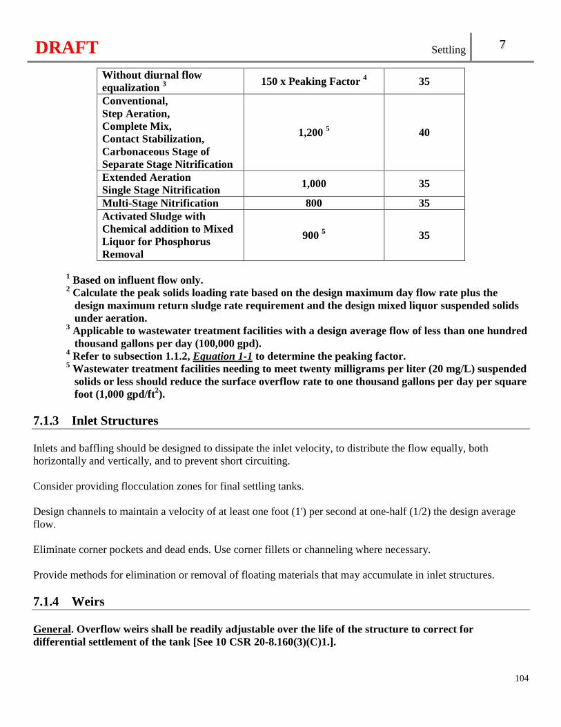
DRAFT Settling 7
104
Without diurnal flow equalization 3 150 x Peaking Factor 4 35
Conventional, Step Aeration, Complete Mix, Contact Stabilization, Carbonaceous Stage of Separate Stage Nitrification
1,200 5 40
Extended Aeration Single Stage Nitrification
1,000 35
Multi-Stage Nitrification 800 35 Activated Sludge with Chemical addition to Mixed Liquor for Phosphorus Removal
900 5 35
1 Based on influent flow only. 2 Calculate the peak solids loading rate based on the design maximum day flow rate plus the
design maximum return sludge rate requirement and the design mixed liquor suspended solids under aeration.
3 Applicable to wastewater treatment facilities with a design average flow of less than one hundred thousand gallons per day (100,000 gpd).
4 Refer to subsection 1.1.2, Equation 1-1 to determine the peaking factor. 5 Wastewater treatment facilities needing to meet twenty milligrams per liter (20 mg/L) suspended
solids or less should reduce the surface overflow rate to one thousand gallons per day per square foot (1,000 gpd/ft2).
7.1.3 Inlet Structures Inlets and baffling should be designed to dissipate the inlet velocity, to distribute the flow equally, both horizontally and vertically, and to prevent short circuiting. Consider providing flocculation zones for final settling tanks. Design channels to maintain a velocity of at least one foot (1') per second at one-half (1/2) the design average flow. Eliminate corner pockets and dead ends. Use corner fillets or channeling where necessary. Provide methods for elimination or removal of floating materials that may accumulate in inlet structures. 7.1.4 Weirs General. Overflow weirs shall be readily adjustable over the life of the structure to correct for differential settlement of the tank [See 10 CSR 20-8.160(3)(C)1.].
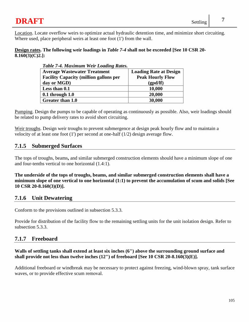
DRAFT Settling 7
105
Location. Locate overflow weirs to optimize actual hydraulic detention time, and minimize short circuiting. Where used, place peripheral weirs at least one foot (1') from the wall. Design rates. The following weir loadings in Table 7-4 shall not be exceeded [See 10 CSR 20-8.160(3)(C)2.]:
Table 7-4. Maximum Weir Loading Rates. Average Wastewater Treatment Facility Capacity (million gallons per day or MGD)
Loading Rate at Design Peak Hourly Flow
(gpd/lf) Less than 0.1 10,000 0.1 through 1.0 20,000 Greater than 1.0 30,000
Pumping. Design the pumps to be capable of operating as continuously as possible. Also, weir loadings should be related to pump delivery rates to avoid short circuiting. Weir troughs. Design weir troughs to prevent submergence at design peak hourly flow and to maintain a velocity of at least one foot (1') per second at one-half (1/2) design average flow. 7.1.5 Submerged Surfaces The tops of troughs, beams, and similar submerged construction elements should have a minimum slope of one and four-tenths vertical to one horizontal (1.4:1). The underside of the tops of troughs, beams, and similar submerged construction elements shall have a minimum slope of one vertical to one horizontal (1:1) to prevent the accumulation of scum and solids [See 10 CSR 20-8.160(3)(D)]. 7.1.6 Unit Dewatering Conform to the provisions outlined in subsection 5.3.3. Provide for distribution of the facility flow to the remaining settling units for the unit isolation design. Refer to subsection 5.3.3. 7.1.7 Freeboard Walls of settling tanks shall extend at least six inches (6") above the surrounding ground surface and shall provide not less than twelve inches (12") of freeboard [See 10 CSR 20-8.160(3)(E)]. Additional freeboard or windbreak may be necessary to protect against freezing, wind-blown spray, tank surface waves, or to provide effective scum removal.
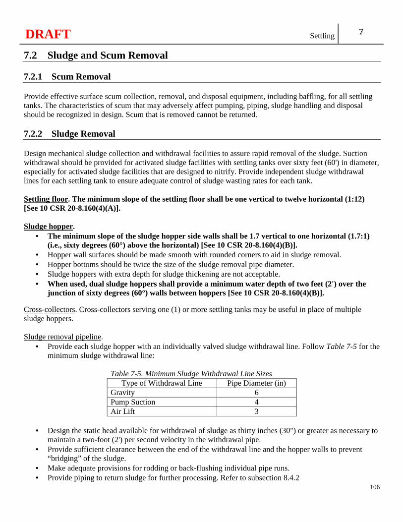
DRAFT Settling 7
106
7.2 Sludge and Scum Removal 7.2.1 Scum Removal Provide effective surface scum collection, removal, and disposal equipment, including baffling, for all settling tanks. The characteristics of scum that may adversely affect pumping, piping, sludge handling and disposal should be recognized in design. Scum that is removed cannot be returned. 7.2.2 Sludge Removal Design mechanical sludge collection and withdrawal facilities to assure rapid removal of the sludge. Suction withdrawal should be provided for activated sludge facilities with settling tanks over sixty feet (60') in diameter, especially for activated sludge facilities that are designed to nitrify. Provide independent sludge withdrawal lines for each settling tank to ensure adequate control of sludge wasting rates for each tank. Settling floor. The minimum slope of the settling floor shall be one vertical to twelve horizontal (1:12) [See 10 CSR 20-8.160(4)(A)]. Sludge hopper.
• The minimum slope of the sludge hopper side walls shall be 1.7 vertical to one horizontal (1.7:1) (i.e., sixty degrees (60°) above the horizontal) [See 10 CSR 20-8.160(4)(B)].
• Hopper wall surfaces should be made smooth with rounded corners to aid in sludge removal. • Hopper bottoms should be twice the size of the sludge removal pipe diameter. • Sludge hoppers with extra depth for sludge thickening are not acceptable. • When used, dual sludge hoppers shall provide a minimum water depth of two feet (2') over the
junction of sixty degrees (60°) walls between hoppers [See 10 CSR 20-8.160(4)(B)]. Cross-collectors. Cross-collectors serving one (1) or more settling tanks may be useful in place of multiple sludge hoppers. Sludge removal pipeline.
• Provide each sludge hopper with an individually valved sludge withdrawal line. Follow Table 7-5 for the minimum sludge withdrawal line:
Table 7-5. Minimum Sludge Withdrawal Line Sizes
Type of Withdrawal Line Pipe Diameter (in) Gravity 6 Pump Suction 4 Air Lift 3
• Design the static head available for withdrawal of sludge as thirty inches (30") or greater as necessary to
maintain a two-foot (2') per second velocity in the withdrawal pipe. • Provide sufficient clearance between the end of the withdrawal line and the hopper walls to prevent
“bridging” of the sludge. • Make adequate provisions for rodding or back-flushing individual pipe runs. • Provide piping to return sludge for further processing. Refer to subsection 8.4.2
DRAFT Settling 7
107
Sludge removal control. Separate settling tank sludge lines may drain to a common sludge well. Provide sludge wells equipped with telescoping valves or other appropriate equipment for viewing, sampling, and controlling the rate of sludge withdrawal. Provide a means of measuring the sludge removal rate. Air-lift sludge removal is not appropriate for the removal of primary sludges.
7.3 Protective and Service Facilities 7.3.1 Operator Protection Safety features shall appropriately include machinery covers, life lines, all stairways and walkways with handrails, and slip resistant surfaces. Also, refer to section 5.6 [See 10 CSR 20-8.160(5)(A)]. 7.3.2 Mechanical Maintenance Access The design shall provide for convenient and safe access to routine maintenance items such as gear boxes, scum removal mechanism, baffles, weirs, inlet stilling baffle areas, and effluent channels [See 10 CSR 20-8.160(5)(B)].
7.3.3 Hosing Equipment Provide hosing equipment for routine flushing of walls and walkways at all facilities. Where water supply is not available, a pump with hose connection may be used. Refer to subsection 5.5.4 for wastewater treatment facility water supplies. 7.3.4 Electrical Equipment, Fixtures, and Controls For electrical equipment, fixtures, and controls in enclosed settling basins and scum tanks, where hazardous concentrations of flammable gases or vapors may accumulate, refer to subsection 5.5.2. The fixtures and controls shall be located so as to provide convenient and safe access for operation and maintenance [See 10 CSR 20-8.160(5)(C)]. Provide adequate area lighting.
7.4 High-Rate and Chemically Enhanced Settling High-rate and chemically enhanced settling units are evaluated on a case-by-case basis. Design standards, operating data, and experience for this process are not well established. Therefore, design of these units should be based upon experience at similar full scale installations or thoroughly documented prototype testing with the particular wastewater. Refer to section 1.4 for pilot testing requirements.

DRAFT
108
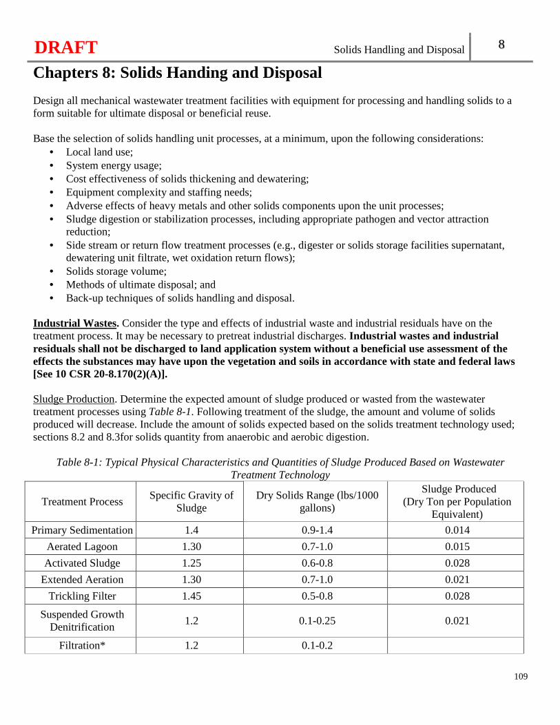
DRAFT Solids Handling and Disposal 8
Chapters 8: Solids Handing and Disposal
109
Design all mechanical wastewater treatment facilities with equipment for processing and handling solids to a form suitable for ultimate disposal or beneficial reuse. Base the selection of solids handling unit processes, at a minimum, upon the following considerations:
• Local land use; • System energy usage; • Cost effectiveness of solids thickening and dewatering; • Equipment complexity and staffing needs; • Adverse effects of heavy metals and other solids components upon the unit processes; • Sludge digestion or stabilization processes, including appropriate pathogen and vector attraction
reduction; • Side stream or return flow treatment processes (e.g., digester or solids storage facilities supernatant,
dewatering unit filtrate, wet oxidation return flows); • Solids storage volume; • Methods of ultimate disposal; and • Back-up techniques of solids handling and disposal.
Industrial Wastes. Consider the type and effects of industrial waste and industrial residuals have on the treatment process. It may be necessary to pretreat industrial discharges. Industrial wastes and industrial residuals shall not be discharged to land application system without a beneficial use assessment of the effects the substances may have upon the vegetation and soils in accordance with state and federal laws [See 10 CSR 20-8.170(2)(A)]. Sludge Production. Determine the expected amount of sludge produced or wasted from the wastewater treatment processes using Table 8-1. Following treatment of the sludge, the amount and volume of solids produced will decrease. Include the amount of solids expected based on the solids treatment technology used; sections 8.2 and 8.3for solids quantity from anaerobic and aerobic digestion.
Table 8-1: Typical Physical Characteristics and Quantities of Sludge Produced Based on Wastewater Treatment Technology
Treatment Process Specific Gravity of
Sludge Dry Solids Range (lbs/1000
gallons)
Sludge Produced (Dry Ton per Population
Equivalent)
Primary Sedimentation 1.4 0.9-1.4 0.014
Aerated Lagoon 1.30 0.7-1.0 0.015
Activated Sludge 1.25 0.6-0.8 0.028
Extended Aeration 1.30 0.7-1.0 0.021
Trickling Filter 1.45 0.5-0.8 0.028
Suspended Growth Denitrification
1.2 0.1-0.25 0.021
Filtration* 1.2 0.1-0.2
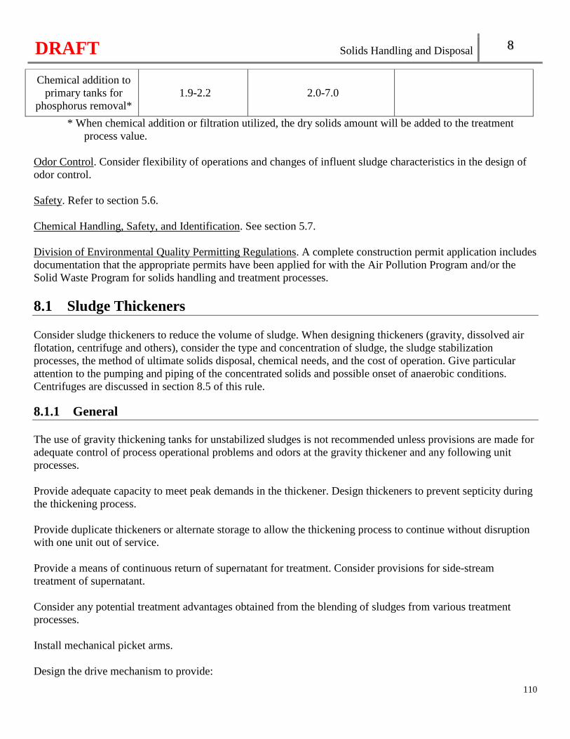
DRAFT Solids Handling and Disposal 8
110
Chemical addition to primary tanks for
phosphorus removal* 1.9-2.2 2.0-7.0
* When chemical addition or filtration utilized, the dry solids amount will be added to the treatment process value.
Odor Control. Consider flexibility of operations and changes of influent sludge characteristics in the design of odor control. Safety. Refer to section 5.6. Chemical Handling, Safety, and Identification. See section 5.7. Division of Environmental Quality Permitting Regulations. A complete construction permit application includes documentation that the appropriate permits have been applied for with the Air Pollution Program and/or the Solid Waste Program for solids handling and treatment processes.
8.1 Sludge Thickeners Consider sludge thickeners to reduce the volume of sludge. When designing thickeners (gravity, dissolved air flotation, centrifuge and others), consider the type and concentration of sludge, the sludge stabilization processes, the method of ultimate solids disposal, chemical needs, and the cost of operation. Give particular attention to the pumping and piping of the concentrated solids and possible onset of anaerobic conditions. Centrifuges are discussed in section 8.5 of this rule.
8.1.1 General The use of gravity thickening tanks for unstabilized sludges is not recommended unless provisions are made for adequate control of process operational problems and odors at the gravity thickener and any following unit processes. Provide adequate capacity to meet peak demands in the thickener. Design thickeners to prevent septicity during the thickening process. Provide duplicate thickeners or alternate storage to allow the thickening process to continue without disruption with one unit out of service. Provide a means of continuous return of supernatant for treatment. Consider provisions for side-stream treatment of supernatant. Consider any potential treatment advantages obtained from the blending of sludges from various treatment processes. Install mechanical picket arms. Design the drive mechanism to provide:
DRAFT Solids Handling and Disposal 8
111
• Sufficient torque capacity to handle the maximum solids concentration and blanket thickness anticipated; and
• A high torque alarm and overload device. Use corrosion resistant metallic components in gravity thickeners. 8.1.2 Gravity Systems Secondary clarifiers or gravity thickeners sufficiently sized for clarification provide solids thickening. However, the use of mechanical stirring devices significantly improves the performance of gravity thickeners. Mechanical thickeners employ low speed stirring mechanisms for continuous mixing and flocculation within the zone of solids concentration. Base the design of gravity thickeners on the following:
• Primary sludge solids loading of twenty to thirty pounds per day per square foot (20-30 lbs/day/ft2); and • Combined primary and waste activated sludge loading of five to fourteen pounds per day per square foot
(5-14 lbs/day/ft2). Conventional overflow rates for gravity thickeners should be in the range of four hundred to eight hundred gallons per day per square foot (400-800gpd/ft2). Include the basis for the surface loading rates. The minimum side water depth for conventional gravity thickeners shall be ten feet (10’) [See 10 CSR 20-8.170(3)]. Consider bottom slope greater than one and one-half inches per radial foot (1.5”/ft) for circular thickeners. Provide for solids storage in the gravity solids thickener, if sufficient storage is unavailable within other external tankage. Provide a means to control and adjust the solids withdrawal from gravity thickeners, such as variable speed pumps. Provide bottom scraping equipment to enhance solids removal. The scraper mechanism peripheral velocity can range from fifteen to twenty feet per minute range (15-20 ft/min).
• Design the scraper mechanical train to be capable of withstanding extra heavy torque loads. The normal working torque load should not exceed ten percent (10%) of the rated torque load.
• Provide a method to correct blockage of the scraper mechanism and restore operation from a stalled position.
Base alternative designs on data obtained from a pilot study in accordance with Chapter 5. Evaluate chemical addition and dilution water feed systems for use to optimize performance.
DRAFT Solids Handling and Disposal 8
112
8.1.3 Dissolved Air Flotation Equip dissolved air flotation (DAF) basins with bottom scrapers to remove settled solids and surface skimmers to remove the floatables established through release of pressurized air into the sludge inflow. The bottom scraper should function independently of the surface skimmer mechanism. Enclose dissolved air flotation units in a building. Provide a positive air ventilation system and odor control. Conventional design parameters include:
• Maximum hydraulic loading rate of two gallons per minute per square foot of surface area (2 gal/min/sq. ft.).
• A solids loading rate in the range of 0.4 to 1.0 pounds per hour per square foot of surface area (lb/hr/sq. ft.) without chemical addition. A solids loading rate of up to 2.5 lbs/hr/sq. ft. may be used if appropriate chemical addition is provided.
• An air supply to sludge solids weight ratio in the range of 0.02 to 0.04. The recycle ratio can range from thirty percent to one hundred fifty percent (30-150%). If potable water is not available, the recycle pressurization system should utilize DAF effluent or secondary effluent. Design the retention tank system for a minimum pressure of forty pounds per square inch (40 psig). Provide a polymer feed system. Design a multiple or variable speed skimmer such as to allow normal operation in the less than one foot per minute (1 fpm) range, with the capability of a speed increase to twenty-five feet per minute (25 fpm). 8.1.4 Mechanical Solids Thickening Gravity belt, rotary drum, dissolved air flotation, screw presses, and centrifuges are acceptable for mechanical thickening of primary, secondary, and combined sludges. Provide a means of chemically conditioning prior to mechanical thickening. Size mechanical thickeners to be capable of processing the maximum weekly sludge produced in under thirty-five (35) hours, unless the equipment is designed to be operated unmanned. If the facility operates with multiple shifts or is constantly manned, include that operational information and processing schedule. When a period of unmanned operation is anticipated as a normal operating condition, provide appropriate instrumentation and fail safe monitoring and alarms. Where duplicate units are not provided, provide adequate sludge storage facilities to store sludge for the period of time anticipated for repairs to be made if the dewatering device is taken out of service for repair.
8.2 Anaerobic Solids Digestion 8.2.1 General
DRAFT Solids Handling and Disposal 8
113
Configuration. Consider facilities for solids storage and supernatant separation in an additional unit, depending on raw sludge concentration and disposal methods for solids and supernatant. Depth. For those units proposed to serve as supernatant separation tanks, the depth should be sufficient to allow for the formation of a reasonable depth of supernatant liquor.
• A minimum sidewater depth of twenty feet (20') is recommended. • Provide for a minimum of six feet (6’) storage depth for supernatant liquor.
Maintenance provisions. To facilitate draining, cleaning and maintenance, the following features are recommended:
• Slope. The tank bottom should slope to drain toward the withdrawal pipe. For tanks equipped with a suction mechanism for withdrawal of solids, a bottom slope of one to twelve (1:12) or greater is recommended. Where the solids are to be removed by gravity alone, one to four (1:4) slope is recommended.
• Access manholes. Provide at least two (2) thirty-six inch (36") diameter access manholes in the top of the tank in addition to the gas dome. Provide stairways to access manholes. Provide a separate sidewall manhole that is located and sized to facilitate the use of mechanical equipment to remove grit and sand. The side wall access manhole may be buried in the earthen bank insulation.
• Safety. Nonsparking tools, safety lights, rubber-soled shoes, safety harness, gas detectors for inflammable and toxic gases, and at least two (2) self-contained breathing units shall be provided for emergency use [See 10 CSR 20-8.170(4)(A)1.].
• Toxic Materials. Anaerobic digestion is not recommended if wastewater analysis shows the presence of undesirable materials, such as high concentrations of sulfates, heavy metals, or other compounds that may inhibit digestion.
• Provide each digester with a means for transferring a portion of its contents to other digesters. Design multiple digester facilities with means for returning supernatant from the settling digester units to appropriate points for treatment.
Alarms shall be installed to warn of [See 10 CSR 20-8.170(4)(A)2.]:
• Any drop of the liquid level below minimum operating elevation; and • Low pressure in the space above the liquid level.
Consider automatic shutdown controls to prevent equipment failure. 8.2.2 Solids Production Base the design solids handling and disposal capacity on a maximum solids concentration of five percent (5%) without additional thickening. Base the dry weight solids production values on the following for the listed processes:
• Primary plus waste activated sludge of at least 0.12 lb/PE/day; and • Primary plus fixed film sludge - at least 0.09 l b /PE/day.
Volatile suspended solids loading should not exceed one hundred pounds per one thousand cubic feet per day
(100 lb/1,000 ft3/ day).
DRAFT Solids Handling and Disposal 8
114
8.2.3 Solids Inlets, Outlets, and High Level Emergency Overflow Provide multiple solids inlets and draw-offs and, where used, multiple recirculation suction and discharge points to facilitate flexible operation and effective mixing of the digester contents unless adequate mechanical mixing is provided within the digester. Inlet Configurations. One inlet should discharge above the liquid level and be located at approximately the center of the tank to assist in scum breakup. The second inlet should be opposite of the suction line at approximately the two-thirds (2/3) diameter point across the digester. Inlet Discharge Location. Raw sludge inlet discharge points should be so located as to minimize short circuiting to the digested solids or supernatant draw-offs. Solids Withdrawal. Withdraw solids from the bottom of the tank. The bottom withdrawal pipe should be interconnected with the necessary valving to the recirculation piping to increase operational flexibility when mixing the tank contents. Emergency Overflow. An unvalved vented overflow shall be provided to prevent damage to the digestion tank and cover in case of accidental overfilling [See 10 CSR 20-8.170(4)(B)]. Pipe this emergency overflow back to the treatment process or side stream treatment facility. 8.2.4 Tank Capacity Standard Design. The minimum tank capacity for domestic or municipal wastewater should
• Have forty to fifty percent (40%-50%) volatile matter in the digested solids; • Have the ability to remove digested solids frequently from the process; and • Have a digestion temperature maintained at ninety-five degrees Fahrenheit (95°F) for fifteen (15) days. The
minimum days of detention may need extended to longer periods for periods for solids stabilized within the primary digester to achieve pathogen control and vector attraction reduction.
The design of anaerobic systems can be completely-mixed; moderately mixed; or multi-stage. The design parameters for each digestion system are provided below.
• Completely-mixed systems. For well mixed digestions systems, the system may be loaded at a rate up to
eighty pounds of volatile solids per one thousand cubic feet of volume per day (80 lbs/1000 ft3/d) or at a volumetric loading that provides fifteen (15) days or more detention time in the active digestion volume in the active digestion units. Consider grit accumulation, when determining the digester volume. � Confined mixing systems include arrangements where gas or solids flows are directed through
vertical channels; and mechanical stirring, or pumping systems. Ensure complete turnover of digestion volume every thirty (30) minutes in either confined mixing or unconfined continuously discharging gas mixing systems. For tanks over sixty feet (60’) in diameter, use multiple mixing devices.
� Use the number of discharge points and gas flow rates shown for the various tank diameters as listed in this section for design of the unconfined, sequentially discharging gas mixing systems.
� Supply a minimum gas flow of fifteen cubic feet per minute per thousand cubic feet (15
ft3/min/1000 ft3) of digestion volume. Use flow measuring devices and throttling valves to provide the minimum gas flow.
DRAFT Solids Handling and Disposal 8
115
• Moderately-mixed systems. For digestion systems where mixing is accomplished only by circulating solids through an external heat exchanger, the system may be loaded at a rate up to forty pounds of
volatile solids per one thousand cubic feet of volume per day (40 lbs/1000 ft3/d) or at a volumetric rate that provides not less than a thirty (30) day detention time in the active digestion units. This loading may be modified depending upon the degree of mixing provided. Include provisions for mixing scum. Where actual data is not available, use the following unit capacities for facilities treating domestic wastewater:
� Primary facility— 3 ft3/PE heated or 4 ft3/PE unheated
� Primary and standard rate filter facility— 4 ft3/PE heated or 5 ft3/PE unheated
� Primary and high rate filter facility— 4 ft3/PE heated or 5.5 ft3/PE unheated • Multistage Systems. For digestion systems utilizing two stages (primary and secondary units), the first
stage (primary) may be either completely mixed or moderately mixed and loaded in accordance with completely or moderately mixed systems. Design the second stage (secondary) unit for solids storage, concentration and gas collection with no credit for solids digestion volume.
• Provide Digester Mixing Facilities for mixing the digester contents where necessary for proper digestion by reason of loading rates or other features of the system. Where solids recirculation pumps are used for mixing, provide in accordance with this subsection.
For cases in which the composition of sludge to be digester has been established, compute the total digestion tank capacity based upon such factors as:
• Volume of sludge added; • The percent solids and character; • The temperature to be maintained in the digesters; • The degree or extent of mixing to be obtained; • The degree of volatile solids reduction; • The solids retention time at peak loadings; • Method of solids disposal; • The size of the installation with appropriate allowances for gas, scum, supernatant, and digested solids
storage; and • Excluding the volume of secondary digesters of two-stage series digestion systems which are utilized for
digested solids storage and concentration. 8.2.5 Gas Collection, Piping, and Appurtenances General. Design all portions of the gas system, including the space above the tank liquor, storage facilities and piping, so that under all normal operating conditions, including solids withdrawal, the gas will be maintained under positive pressure. Adequately ventilate all enclosed areas where any gas leakage might occur. Safety equipment. Where gas is produced, all necessary safety facilities shall [See 10 CSR 20-8.170(4)(C)1.]:
• Provide pressure and vacuum relief valves and flame traps, together with automatic safety shutoff valves and protect from freezing;
• Not install water seal equipment; and • House gas safety equipment and gas compressors in a separate room with an exterior entrance.
DRAFT Solids Handling and Disposal 8
116
Gas piping and condensate. Design gas piping with a diameter of four inches (4”) or greater. A smaller diameter pipe at the gas production meter is acceptable.
• Slope gas piping to condensate traps at low points. • Do not use float-controlled condensate traps. • Protect condensation traps from freezing. • Provide tightly fitted self-closing doors at connecting passageways and tunnels that connect digestion
facilities to other facilities minimize the spread of gas. • Piping galleries shall be ventilated in accordance with subsection 8.2.5, Ventilation [See 10 CSR 20-
8.170(4)(C)2.]. • Equip gas piping lines for anaerobic digesters with closed type indicating gauges, which typically read
directly in inches of water. Provide three gauges; one to measure the main line pressure; a second to measure the pressure to gas-utilization equipment; and the third to measure pressure to waste burners.
• Provide gas tight shut-off and vent cocks. Extend the vent piping outside the building, and provide a screen for the opening and design to prevent the entrance of rainwater.
• Protect all piping of the manometer system with safety equipment. • Design gas piping to maintain digester gas velocities less than twelve feet per second (12 fps).
Gas utilization equipment. Locate gas-fired boilers for heating digesters in a separate room not connected to the digester gallery. The separated room would not ordinarily be classified as hazardous location. Design suitable flame traps on the gas lines to these units. Electrical fixtures, equipment, and controls. Electrical fixtures, equipment, and controls shall comply with the National Electrical Manufacturers Association (NEMA) 4X enclosure rating where necessary. Electrical equipment, fixtures, and controls, in places enclosing and adjacent to anaerobic digestive appurtenances where hazardous gases are normally contained in the tanks and/or piping shall comply with the National Electrical Manufacturers Association (NEMA) 4X enclosure rating where necessary [See 10 CSR 20-8.170(4)(C)3.]. Isolate digester galleries from normal operating areas to avoid an extension of the hazardous location in accordance with subsection 8.2.4, Ventilation. Waste gas.
• Location. Waste gas burners should be readily accessible and located at least fifty feet (50’) away from any facility structure if placed at ground level or may be located on the roof of the control building if sufficiently removed from the tank. Locate waste gas burners at a sufficient height to prevent injury to personnel due to wind or downdraft conditions.
• Gas Burners. Equip all waste gas burners with automatic ignition, such as pilot light or a device using a photoelectric cell sensor. Consider the use of natural or propane gas to insure reliability of the pilot light. In remote locations it may be permissible to discharge the gas to the atmosphere through a return-bend screened vent terminating at least ten feet (10') above the ground surface, provided that the assembly incorporates a flame trap and is in compliance with all applicable Missouri air regulations.
Ventilation. Any underground enclosures connecting with digestion tanks or containing solids or gas piping or equipment shall be provided with forced ventilation for dry wells in accordance with subsection 4.1.7 and 4.1.7, Size [See 10 CSR 20-8.170(4)(C)4.].
• The piping gallery for digesters should not be connected to other passages. Where used, tightly fitting, provide self-closing doors at connecting passageways and tunnels to minimize the spread of gas.
• The ventilation shall be at least twelve (12) complete air changes per hour for Class I, Division 2,
DRAFT Solids Handling and Disposal 8
117
Group D locations including enclosed areas without a gas tight partition from the digestion tank or areas containing gas compressors, sediment traps, drip traps, gas scrubbers, or pressure regulating and control valves, if continuous [See 10 CSR 20-8.170(4)(C)4.B.].
Meter. Provide a gas meter with bypass to meter total production for each active digestion unit. Design the gas meters specifically for contact with corrosive and dirty gases. Use orifice plate, turbine, or vortex meters. Positive displacement meters should not be utilized.
• Total gas production for two-stage digestion systems operated in series may be measured by a single gas meter with proper interconnected gas piping.
• Where multiple primary digestion units are utilized with a single secondary digestion unit, provide a gas meter for each primary digestion unit.
• The secondary digestion unit may be interconnected with the gas measurement unit of one of the primary units.
• Properly valve interconnected gas piping with gas tight gate valves to allow measurement of gas production from either digestion unit and maintenance of either digestion unit.
8.2.6 Digester Heating Insulation. Wherever possible digestion tanks should be constructed above groundwater level and be suitably insulated to minimize heat loss. Heating facilities. Sludge may be heated by circulating the sludge through external heaters or by heating units located inside the digestion tank.
• External heating. Design piping to provide for the preheating of feed sludge before introduction to the digesters. Make provisions in the layout of the piping and valving to facilitate heat exchanger tube removal and cleaning of these lines. Size heat exchanger sludge piping adequately. Heat exchangers should have a heating capacity of one hundred thirty percent (130%) of the peak heating capacity to account for the occurrence of sludge tube fouling.
• Other heating methods. � Hot water heating coils affixed to the walls of the digester or other types of internal heating
equipment should not be used, especially if emptying the digester contents is necessary for repair. � Other systems and devices have been developed recently to provide both mixing and heating of
anaerobic digester contents. These systems will be reviewed on their own merits; see Chapter 5. Submit operating data detailing their reliability, operation, and maintenance characteristics.
Heating capacity. Considering insulation provisions and ambient cold weather conditions, provide sufficient heating capacity to consistently maintain the design sludge temperature.
• Where digester tank gas is used for sludge heating, provide an auxiliary fuel supply. • The design operating temperature should be in the range of 85°F to 100°F where optimum mesophilic
digestion is utilized. • Consider the provision of standby heating capacity or the use of multiple units sized to provide the
necessary heating, unless acceptable alternative means of handling raw sludge are provided for the extended period that a digestion process outage is experienced due to heat loss.
Hot water internal heating controls.
• Mixing valves. Provide a suitable automatic mixing valve to temper the boiler water with return water so that the inlet water to the heat jacket can be held below a temperature at which caking will be
DRAFT Solids Handling and Disposal 8
118
accentuated. Manual control should also be provided by suitable bypass valves. • Boiler controls. Provide the boiler with suitable automatic controls to maintain the boiler temperature at
approximately one hundred eighty degrees Fahrenheit (180 °F) to minimize corrosion and to shut off the main gas supply in the event of pilot burner or electrical failure, low boiler water level, low gas pressure, or excessive boiler water temperature or pressure.
• Boiler Water Pumps. Seal and size boiler water pumps to meet the operating conditions of temperature, operating head, and flow rate. Provide duplicate units.
• Provide thermometers to show inlet and outlet temperatures of the solids, hot water feed, hot water return and boiler water. It is recommended that a facility have a temperature probe and recording device to continuously record digester temperature.
• Water Supply. The chemical quality should be checked for suitability for use as a water supply. Refer to subsection 5.5.4 regarding indirect water supply connections.
• External Heater Operating Controls. Provide all controls necessary to ensure effective and safe operation. Consider duplicate units in critical elements.
8.2.7 Biotowers Reserved. 8.2.8 Supernatant Withdrawal Where supernatant separation is to be used to concentrate solids in the digester units and increase digester solids retention time, design for ease of operation and positive control of supernatant quality. Piping size. Supernatant piping should be at least six inches (6") in diameter. Withdrawal arrangements.
• Withdrawal levels. Arrange piping so that withdrawal can be made from three (3) or more levels in the digester. Provide a positive pressure, unvalved vented overflow. The emergency overflow shall be piped back to the treatment process or side stream treatment unit [See 10 CSR 20-8.170(4)(H)2.A.].
• Withdrawal Selection. On fixed cover tanks, the supernatant withdrawal level should be selected by means of interchangeable extensions at the discharge end of the piping. � Supernatant selector. A fixed screen supernatant selector or similar type device may be used only in
an unmixed secondary digestion unit. � If a supernatant selector is provided, locate at least one (1) other draw-off level in the supernatant
zone of the tank in addition to the unvalved emergency supernatant draw-off pipe. Provide high pressure backwash facilities.
Sampling. Provide for sampling at each supernatant draw-off level. Sampling pipes should be at least one and one-half inches (1 1/2") in diameter and terminate at a suitably-sized sampling sink or basin. Alternate supernatant disposal. Design supernatant return and disposal facilities to alleviate adverse hydraulic and organic effects on facility operations. For facilities that have nutrient removal (e.g., phosphorus, ammonia nitrogen), provide a separate supernatant side stream treatment system.
DRAFT Solids Handling and Disposal 8
119
8.2.9 Energy Control Utilization of digester gas as a heating fuel source is encouraged whenever practical. Optimize the production of methane gas (CH4). Provide sufficient heating capacity to consistently maintain the design temperature necessary for solids stabilization. For emergency usage, provide an alternate source of fuel and a boiler or other heat source capable of using the alternate fuel. Locate sludge heating devices with open flames above grade in areas separated from locations of gas production or storage. If designing a cogeneration system, include the following parameters:
• Volume of gas produced by digesters;
• Digester gas energy value in British Thermal Units per cubic foot (BTUs/ft3); • Gas composition; • Gas storage capability; and • Gas pretreatment, including filtration.
8.3 Aerobic Solids Digestion 8.3.1 General Aerobic digestion can be used to stabilize primary sludge, secondary sludge or a combination of the two. Digestion is accomplished in single or multiple tanks designed to provide effective air mixing, reduction of the organic matter, supernatant separation and sludge concentration under controlled conditions. Digestion tanks. Provide multiple digestion units capable of independent operation in all facilities where the design average flow is equal to or greater than one hundred thousand gallons per day (100,000 gpd). For facilities less than one hundred thousand gallons per day (100,000 gpd), a single solids digestion tank may be used where adequate provision is made for sludge handling. For an aerobic digester that concentrates waste sludge only by decanting a digester tank, the maximum solids concentration used to determine the total retention time is two percent (2.0%) unless supporting data is submitted to increase the solids concentration up to three percent (3.0%). Equip aerobic digesters to control, suppress, or remove excessive foam. Consider provisions for the capture and control of foam outside the structure in the event of failure of equipment, seals, pipe penetrations, or access ports. 8.3.2 Design Solids Production For determining design solids handling, base solids production values from aerobic digesters on a maximum solids concentration of two percent (2.0%) without additional thickening. Use the following solids production values on a dry weight basis per population equivalent for the listed processes:
DRAFT Solids Handling and Disposal 8
120
• For primary plus waste activated sludge, a minimum of 0.16 lbs/PE/day • For primary plus fixed film sludge, a minimum of 0.12 lb/PE/day
Design the digester volume to be greater than 25% of the design average flow of the treatment works. Mixing and Air Requirements. Design aerobic solids digestion tanks to provide effective mixing. Provide sufficient air to keep the solids in suspension and maintain dissolved oxygen between one and two (1–2) mg/l.
• For adequate mixing and oxygen, provide an air supply of at least thirty (30) cfm per one thousand (1000) cubic feet of tank volume with the largest blower out-of-service.
• If diffusers are used, the nonclog type is recommended, and they should be designed to provide continuity of service.
• If mechanical turbine aerators are utilized, provide at least two turbine aerators per tank for continuity of service.
• If mechanical aerators are utilized, provide a minimum of 1.0 horsepower per one thousand (1000) cubic feet. Mechanical aerators are not recommended for use in aerobic digesters where freezing conditions will cause ice build-up on the aerator and support structures. Include protection against freezing conditions when using mechanical aerators.
• Base the minimum quantity of oxygen provided on two and one-tenth pounds (2.1 lbs) of oxygen per pound of volatile solids destroyed for open tank systems; or one and half pounds (1.5 lbs) of oxygen per pound of volatile solids destroyed for thermophilic systems.
A reduction in in hydraulic detention time may be given for aerobic digesters designed to be operated in the extended aeration mode, or coupled with additional stabilization processes, or operated at elevated temperatures. Provide basis for determining the hydraulic detention time. 8.3.3 Tank Capacity Base the determination of tank capacities on such factors as quantity of sludge produced, sludge characteristics, time of aeration and sludge temperature. Volatile solids loading. It is recommended that the volatile suspended solids loading not exceed one hundred pounds per one thousand cubic feet of volume per day (100 lb/1000 ft3/d) in the digestion units. Lower loading rates may be necessary depending on temperature, type of sludge and other factors. Include the volatile solids loading rates. Solids retention time. The minimum solids retention time for stabilization of biological sludges vary depending on type of sludge. Normally, a minimum of fifteen (15) days’ retention should be provided for waste activated sludge and twenty (20) days for combination of primary and waste activated sludge, or primary sludge alone. Where sludge temperature is lower than fifty degrees Fahrenheit (50 °F), consider additional detention time. The following digestion tank capacities are based on a solids concentration of two percent (2.0%) with supernatant separation performed in a separate tank.
• If supernatant separation is performed in the digestion tank, provide a minimum of twenty-five percent (25%) additional volume.
• Provide these capacities unless solids thickening facilities are utilized to thicken the feed solids concentration to greater than two percent (2.0%). If such thickening is provided, the digestion volumes
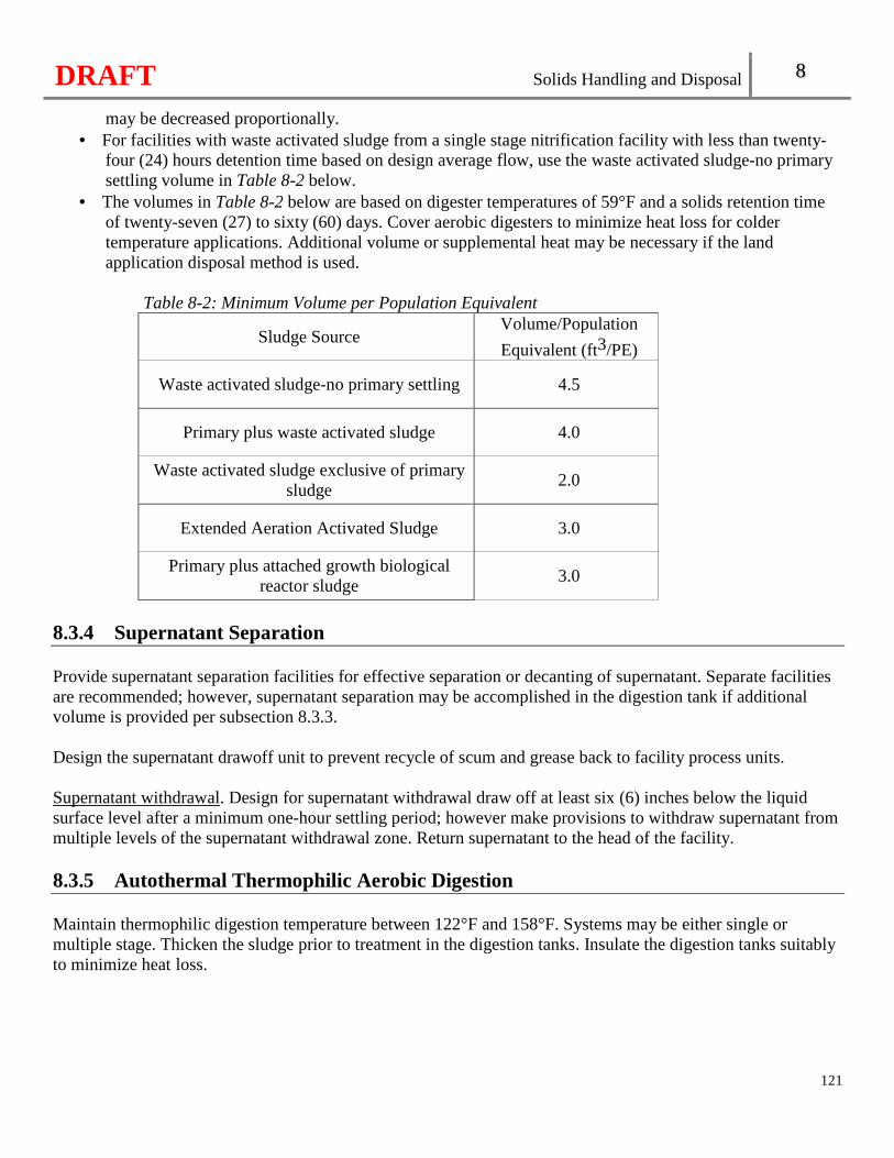
DRAFT Solids Handling and Disposal 8
121
may be decreased proportionally. • For facilities with waste activated sludge from a single stage nitrification facility with less than twenty-
four (24) hours detention time based on design average flow, use the waste activated sludge-no primary settling volume in Table 8-2 below.
• The volumes in Table 8-2 below are based on digester temperatures of 59°F and a solids retention time of twenty-seven (27) to sixty (60) days. Cover aerobic digesters to minimize heat loss for colder temperature applications. Additional volume or supplemental heat may be necessary if the land application disposal method is used.
Table 8-2: Minimum Volume per Population Equivalent
Sludge Source Volume/Population
Equivalent (ft3/PE)
Waste activated sludge-no primary settling 4.5
Primary plus waste activated sludge 4.0
Waste activated sludge exclusive of primary sludge
2.0
Extended Aeration Activated Sludge 3.0
Primary plus attached growth biological reactor sludge
3.0
8.3.4 Supernatant Separation Provide supernatant separation facilities for effective separation or decanting of supernatant. Separate facilities are recommended; however, supernatant separation may be accomplished in the digestion tank if additional volume is provided per subsection 8.3.3. Design the supernatant drawoff unit to prevent recycle of scum and grease back to facility process units. Supernatant withdrawal. Design for supernatant withdrawal draw off at least six (6) inches below the liquid surface level after a minimum one-hour settling period; however make provisions to withdraw supernatant from multiple levels of the supernatant withdrawal zone. Return supernatant to the head of the facility. 8.3.5 Autothermal Thermophilic Aerobic Digestion Maintain thermophilic digestion temperature between 122°F and 158°F. Systems may be either single or multiple stage. Thicken the sludge prior to treatment in the digestion tanks. Insulate the digestion tanks suitably to minimize heat loss.
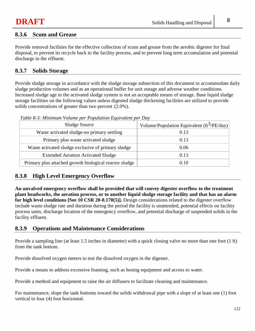
DRAFT Solids Handling and Disposal 8
122
8.3.6 Scum and Grease Provide removal facilities for the effective collection of scum and grease from the aerobic digester for final disposal, to prevent its recycle back to the facility process, and to prevent long term accumulation and potential discharge in the effluent. 8.3.7 Solids Storage Provide sludge storage in accordance with the sludge storage subsection of this document to accommodate daily sludge production volumes and as an operational buffer for unit outage and adverse weather conditions. Increased sludge age in the activated sludge system is not an acceptable means of storage. Base liquid sludge storage facilities on the following values unless digested sludge thickening facilities are utilized to provide solids concentrations of greater than two percent (2.0%).
Table 8-3: Minimum Volume per Population Equivalent per Day
Sludge Source Volume/Population Equivalent (ft3/PE/day) Waste activated sludge-no primary settling 0.13
Primary plus waste activated sludge 0.13
Waste activated sludge exclusive of primary sludge 0.06
Extended Aeration Activated Sludge 0.13
Primary plus attached growth biological reactor sludge 0.10 8.3.8 High Level Emergency Overflow An unvalved emergency overflow shall be provided that will convey digester overflow to the treatment plant headworks, the aeration process, or to another liquid sludge storage facility and that has an alarm for high level conditions [See 10 CSR 20-8.170(5)]. Design considerations related to the digester overflow include waste sludge rate and duration during the period the facility is unattended, potential effects on facility process units, discharge location of the emergency overflow, and potential discharge of suspended solids in the facility effluent.
8.3.9 Operations and Maintenance Considerations Provide a sampling line (at least 1.5 inches in diameter) with a quick closing valve no more than one foot (1 ft) from the tank bottom. Provide dissolved oxygen meters to test the dissolved oxygen in the digester. Provide a means to address excessive foaming, such as hosing equipment and access to water. Provide a method and equipment to raise the air diffusers to facilitate cleaning and maintenance. For maintenance, slope the tank bottoms toward the solids withdrawal pipe with a slope of at least one (1) foot vertical to four (4) foot horizontal.
DRAFT Solids Handling and Disposal 8
123
8.4 Solids Pumps and Piping For solids pumping systems, at a minimum audio-visual alarms shall be provided for pump failure, loss of pressure, and high pressure [See 10 CSR 20-8.170(6)].
8.4.1 Solids Pumps Capacity. Design solids pumping systems with adequate capacity to cover the full range of anticipated solids concentrations and sludge production rates. Account for the higher friction factors associated with the type of solids being pumped in the operating pressure and head loss. Consider varying pump capacity in the design. Provide a rational basis of design. Duplicate units. Provide duplicate units in all installations. Type. Provide plunger pumps, screw feed pumps, recessed impeller type centrifugal pumps, progressive cavity pumps or other types of pumps with demonstrated solids handling capability for handling raw sludge. Where centrifugal pumps are used, provide a parallel positive displacement as an alternate to pump heavy solids concentrations, such as primary or thickened sludge, that may exceed the pumping head of the centrifugal pump. Minimum head. Provide a minimum positive head of twenty-four inches (24") at the suction side of centrifugal type pumps and is recommended for all types of solids pumps. Maximum suction lifts should not exceed ten feet (10') for plunger pumps. Sampling facilities. Unless solids sampling facilities are otherwise provided, install quick closing sampling valves at the solids pumps. The size of valve and piping should be at least one and one-half inches (1.5”) and terminate at a suitably sized sampling sink or floor drain. 8.4.2 Solids Piping Size and head. Solids withdrawal piping should have a minimum diameter of eight inches (8") for gravity withdrawal and four inches (4”) for pump suction and discharge lines. Where withdrawal is by gravity the available head on the discharge pipe should be at least four feet (4’) greater than the projected head loss. Design all solids piping systems to provide a velocity of at least two feet per second (2 fps). Slope. Gravity piping should be laid on uniform grade and alignment.
• The slope of gravity discharge piping should not be less than three percent (3%) for primary sludges and all solids thickened to greater than two percent (2%) solids.
• Slope on gravity discharge piping should not be less than two percent (2%) for aerobically digested solids or waste activated sludge with less than two percent (2%) solids.
• Provide cleanouts for all gravity solids piping. • Include provisions for cleaning, draining and flushing discharge lines. • Suitably locate or otherwise adequately protect all solids piping to prevent freezing.
Supports. Special consideration should be given to the corrosion resistance and continuing stability of supporting systems located inside the digestion tank.
DRAFT Solids Handling and Disposal 8
124
8.5 Solids Dewatering Provide on-site solids dewatering facilities for all mechanical facilities, although the following may be reduced with on-site liquid solids storage facilities or approved off-site solids disposal. For facilities in which solids data is not available or is likely to change considerably in nature, documentation of successful performance from multiple facilities handling similar solids under similar conditions and design criteria may be used to develop appropriate design criteria. 8.5.1 Solids Drying Beds Solids drying beds may be used for dewatering well digested solids from either the anaerobic or aerobic process. Due to the large volume of solids produced by the aerobic digestion process, consider using a combination of dewatering systems or other means of ultimate solids disposal. Unit Sizing. Consider the following items in sizing the solids drying bed area:
• The volume of wet solids produced by existing and proposed processes. • Depth of wet solids drawn to the drying beds. For design purposes, utilize a maximum depth of eight
inches (8”). For operational purposes, the depth of solids placed on the drying bed may increase or decrease from the design depth based on the percent solids content and type of digestion utilized.
• Total digester volume and other wet solids storage facilities. • Degree of solids thickening provided after digestion. • The maximum drawing depth of solids which can be removed from the digester or other solids storage
facilities without causing process or structural problems. • The time necessary on the bed to produce a removable cake. Make adequate provisions or consider
alternative methods for solids dewatering and/or solids disposal facilities for those periods of time during which outside drying of solids on beds is hindered by weather.
• Capacities of auxiliary dewatering facilities. Area. In determining the area of solids drying beds, consider the climatic conditions, the character and volume of the solids to be de-watered, the method and schedule of solids removal and other methods of solids disposal. The sizing of the drying bed may be estimated on the basis of 2.0 ft2/capita when the drying bed is the primary method of de-watering, and 1.0 ft2/capita if it is to be used as a back-up de-watering unit. Percolation type. The lower course of gravel around the underdrains should be properly graded and be twelve inches (12") in depth, extending at least six inches (6") above the top of the underdrains. It is recommended to place this in two (2) or more layers. The top layer of at least three inches (3") should consist of gravel one-eighth inch (1/8") to one-fourth inch (1/4") in size.
• Sand. The top course should consist of at least nine to twelve inches (9”-12”) of clean, hard, and washed coarse sand. The effective size of the sand should be in the range of 0.8 mm to 1.5 mm. The finished sand surface should be level.
• Underdrains. Underdrains should be at least four inches (4") in diameter and laid with open joints. Underdrains should be spaced not more than twenty feet (20') apart and sloped at a minimum of one percent (1%). Lateral tiles should be spaced at eight to ten feet (8-10’). Various pipe materials may be selected provided the pipe is corrosion resistant and appropriately bedded to ensure that the underdrains are not damaged by solids removal equipment. Perforated pipe may also be used. As to the discharge of the underdrain filtrate, refer to subsection 8.5.3.
DRAFT Solids Handling and Disposal 8
125
• Consider additional dewatering provisions to provide a means of decanting the supernatant of solids placed on the solids drying beds. More effective decanting of supernatant may be accomplished with polymer treatment of solids.
• Seal the bottom of the percolation bed in a manner approved by the Department. • Do not use paved surface beds.
Walls. Walls should extend eighteen inches (18") above and at least nine inches (9”) below the surface of the solids drying bed. Extend water tight outer walls down to the bottom of the bed and at least four inches (4”) above the outside grade elevation to prevent soil from washing into the beds. Solids removal. At least two (2) beds should be provided and arranged to facilitate solids removal. Pairs of tracks for percolation type should be on twenty-foot (20') centers. Construct each solids drying bed so as to be readily and completely accessible to mechanical equipment for cleaning and sand replacement. Provide concrete runways spaced to accommodate mechanical equipment. Give special attention to assure adequate access to the areas adjacent to the sidewalls. Provide entrance ramps down to the level of the sand bed. These ramps should be high enough to eliminate the need for an entrance end wall for the solids bed. Solids influent. The solids pipe to the drying beds should terminate at least twelve inches (12") above the surface and be so arranged that it will drain. Provide concrete splash plates for percolation type at solids discharge points. Protective enclosure. Provide a protective enclosure if winter operation is necessary. 8.5.2 Mechanical Dewatering Facilities Make provision to maintain sufficient continuity of service so that solids may be dewatered without accumulation beyond storage capacity. The number of vacuum filters, centrifuges, filter presses, belt filters or other mechanical dewatering facilities should be sufficient to dewater the solids produced with one (1) largest unit out-of-service. Unless other standby facilities are available, provide adequate storage facilities. Provide sufficient storage capacity to handle at least a three (3)-month solids production. Submit documentation justifying the design basis of mechanical dewatering facilities. Auxiliary facilities per vacuum filters. Provide a back-up vacuum pump and filtrate pump installed for each vacuum filter. It is permissible to have an uninstalled back-up vacuum pump or filtrate pump for every three (3) or less vacuum filters, provided that the installed unit can easily be removed and replaced. Ventilation. Provide facilities for ventilation of dewatering area. The exhaust air should be properly conditioned to avoid odor nuisance. Chemical handling enclosures. Completely enclose lime-mixing facilities to prevent the escape of lime dust. Automate chemical handling equipment to eliminate manual lifting. Design the mechanical dewatering units to be capable of handling the maximum weekly solids production in thirty (30) hours, unless the equipment is designed for continuous operation.
DRAFT Solids Handling and Disposal 8
126
8.5.3 Centrifuges Centrifugal dewatering of solids is a process which uses the force developed by fast rotation of a cylindrical drum or bowl to separate the solids from the liquid. Include a solids characterization with the necessary polymer and coagulant dosage to achieve the design solids content. Consider the abrasiveness of each solids supply in scroll selection. Provide adequate solids storage for proper operation. Unless utilizing dual trains, provide the following spare appurtenant equipment with necessary connecting piping and electrical controls to allow easy installation:
• Drive motor. • Gear assembly. • Feed pump.
Provide a variable speed pump for each centrifuge within the feed system. Equip each centrifuge with provisions for variation of scroll speed and pool depth. Provide a crane or monorail for equipment removal or maintenance. Design provision for adequate and efficient wash down of the machine interior. 8.5.4 Belt Press Utilize actual performance data developed from similar operational characteristics for design. Address the impact that anticipated solids variability will have on the design variables for the press as well as chemical conditioning. Provide a second belt filter press or an approved backup method of dewatering whenever:
• A single belt press is operated sixty (60) hours or more within any consecutive five (5) day period, or • The average daily flow received at the treatment works equals or exceeds one million gallons per day (1
MGD). • Utilize appropriate scale-up factors for full-size designs if pilot testing is performed in lieu of full-scale
testing. Design solids feed to be as constant as possible to eliminate difficulties in polymer addition and press operation. Identify the range in feed variability and provide equalization as necessary. Provide a method for uniform solids dispersion on the belt. Consider grinders for the solids feed to the flocculation system. Thickening of the feed solids should be an integral part of the design of the filter press. Consider the following in the filter press design:
• Variable belt speed mechanism. • Belt tracking and belt tensioning equipment. • Belt replacement availability based on evaluation of the belt equipment selection especially if the weave,
material, width, or thickness cannot be reasonably duplicated.
DRAFT Solids Handling and Disposal 8
127
Consider the following in the sizing, design, and location of the filter press: • Drip trays under the press and under the thickener to readily remove filtrate if gravity belt thickening is
employed; • Adequate clearance to the side and floor for maintenance and removal of the dewatered solids; • Location of all electrical panels or other materials that are subject to corrosion out of the area of the
press; and • Adjustable doctor blade clearance.
Provide the polymer selection methodology, accounting for solids variability and anticipated solids loading to the press. Specify the rollers utilized with the belt filter press in the design and the specifications should include:
• Rubber coating or other protective finish. • Maximum frame and roller deflection and operating tension. • Roller bearings that is watertight and rated for a B-10 life of one hundred thousand (100,000) hours.
Criteria for the washwater system:
• High pressure washwater for each belt with a specified operating pressure; • Booster pumps if necessary; • Spray wash systems designed to be cleaned without interference with the system operation; • Particular care in nozzle selections and optional nozzle cleaning systems when recycled wastewater is
used for belt washing; • Replaceable spray nozzles; and • Spray curtains.
Include the following spare appurtenances:
• Complete set of belts; • One set of bearings for each type of press bearing; • Tensioning and tracking sensors; • One set of wash nozzles; • Doctor blade; and • Conditioning or flocculation drive equipment; if duplicate units are not provided.
Belt presses and conveyors shall be provided with emergency pull cords along the entire length of the belt presses and conveyors that will [See 10 CSR 20-8.170(7)(A)]:
• Stop the press in an emergency; and • Trigger an audible alarm.
8.5.5 Screw Press Reserved. 8.5.6 Rotary Fan Press Reserved.
DRAFT Solids Handling and Disposal 8
128
8.5.7 Biomembrane Bags Reserved. 8.5.8 Drainage and Filtrate Disposal Return drainage from beds or filtrate from dewatering units to the wastewater treatment process at appropriate points and rates. Return dewatering sidestreams to the treatment process as far upstream as practicable prior to the biological treatment unit. Provide sampling equipment as needed to monitor drainage and filtrate waste streams. 8.5.9 Dewatering Facilities If it is proposed to dewater or dispose of sludge by other methods, a detailed description of the process and design data is necessary. See Chapter 5 for discussion of new process demonstrations. 8.5.10 Operator Notification Alarm systems shall be provided to notify the operator(s) of conditions that could result in process equipment failure or damage, threaten operator safety, or a solids spill or overflow condition [See 10 CSR 20-8.170(7)(B)]. Provide automatic shutdowns to prevent equipment failure.
8.6 Storage 8.6.1 General Provide solids storage facilities at all treatment facilities. Appropriate storage facilities may consist of any combination of drying beds, lagoons, separate tanks, additional volume in solids stabilization units, pad areas or other means to store either liquid or dried solids. Provide for odor control in solids storage tanks and sludge lagoons including aeration, covering, or other appropriate means so that odors do not create a nuisance at the property boundary. 8.6.2 Design Base the number of days of storage based on the total solids and/or biosolids handling and disposal system. Justify the solids production values for stabilization processes. Design storage areas to minimize tracking of dewatered cake on-site and eliminate runoff from the dewatered cake storage area to other portions of the site or off-site. For dewatered solids, provide concrete or equivalent surfaced facilities with appropriate drainage systems to
DRAFT Solids Handling and Disposal 8
129
store treated solids. Provide drainage systems to return supernatant or other liquids to the headworks of the treatment system. Accommodate daily sludge production volumes and function as an operational buffer for unit outage and adverse weather conditions. Designs utilizing increased sludge age in the activated sludge system as a means of storage are not acceptable. Liquid high pH stabilized sludge will not be stored in a lagoon. Store liquid sludge in a tank or vessel equipped with rapid solids withdrawal mechanisms for solids disposal or retreatment. Limit on-site storage of dewatered high pH stabilized sludge to thirty (30) days. No off-site storage disposal of high pH stabilized sludge allowed. Make provisions for rapid retreatment or disposal of dewatered sludge stored on-site in case of sludge pH decay. For facilities that transport sludge to another facility as the means of disposal, design storage capacity to accommodate at least ten (10) days of sludge production based on maximum month design sludge generation rate. Disposal. Provide drainage facilities for solids vehicle transfer stations to allow any spillage or washdown material to be collected and returned to the wastewater treatment facility or solids storage facility. If the land application method of biosolids disposal is the only means of disposal utilized at a treatment facility, provide storage based on the following considerations, at a minimum:
• Inclement weather effects on access to the application land; • Temperatures including frozen ground and stored biosolids cake conditions; • Haul road restrictions including spring thawing conditions; • Area seasonal rainfall patterns; • Cropping practices on available land; • Potential for increased solids volumes from industrial sources during the design life of the facility; and • Available area for expanding solids storage; • Appropriate pathogen reduction and vector attraction reduction criteria. Provide a minimum range of
one hundred twenty to one hundred eighty (120-180) days storage for the design life of the facility unless a different period is approved on a case-by-case basis.
8.6.3 Sludge and Biosolids Storage Lagoons General sludge storage lagoons may be permitted only upon proof that the character of the sludge and the design mode of operation are such that offensive odors will not result. Where sludge lagoons are permitted, make adequate provisions for other acceptable sludge handling methods in the event of upset or failure of the sludge digestion process. Sludge storage lagoons are temporary facilities and it is not necessary to obtain a solid waste permit under 10 CSR 80. In order to maintain sludge storage lagoons as storage facilities, remove accumulated sludge routinely, but not less than once every two years unless an alternate schedule is approved in the operating permit. Location. Locate sludge lagoons as far as practicable from inhabited areas or areas likely to be inhabited during the lifetime of the structures. Locate the sludge lagoons in accordance with Chapter 11.
DRAFT Solids Handling and Disposal 8
130
Seal. Seal the sludge lagoon bottoms and embankments in accordance with subsection 11.3.3 to prevent leaching into adjacent soils or ground water. Protect the seal to prevent damage from sludge removal activities. Base groundwater monitoring considerations on the recommendations of Missouri Geological Survey. Access. Make provisions for pumping or heavy equipment access for sludge removal from the sludge lagoon on a routine basis. Supernatant Disposal. Return lagoon supernatant to the wastewater treatment process at appropriate points and rates. Provide sampling equipment as needed to monitor supernatant waste streams.
8.7 Chemical Treatment 8.7.1 HEADING The fundamental design areas to be considered include chemical feeding, mixing, and storage capacity. Include chemical treatment operation controls such as pH, contact time and mixture temperature. Provide multiple units unless nuisance-free storage or alternate stabilization methods are available to avoid disruption to treatment works operation when units are not in service. If a single system is provided, provide standby conveyance and mixers, backup heat sources, dual blowers, etc. as necessary. Include a reasonable downtime for maintenance and repair based on data from comparable facilities in the design. Include adequate storage for process, feed, and downtime. Provide either mechanical or aeration agitation to ensure uniform discharge from storage bins. 8.7.2 Equipment Determine the design of the feeding equipment by the treatment facility size, type of alkaline material used, slaking, and operator certification level. Equipment may be either of batch or automated type. Automated feeders may be of the volumetric or gravimetric type depending on accuracy, reliability, and maintenance necessities. Avoid manually operated batch slaking of quicklime (CaO) unless adequate protective clothing and equipment are provided. At small facilities, use hydrated lime [Ca(OH)2] instead of quicklime due to safety and labor-saving reasons. Size feed and slaking equipment to handle a minimum of 150% of the peak sludge flow rate including sludge that may need to be retreated due to pH decay. Store material delivered in bags indoors and elevated above floor level. Use the multi-wall moisture-proof type bags.Design dry bulk storage containers to be as airtight as practical and include a mechanical agitation mechanism
DRAFT Solids Handling and Disposal 8
131
in the dry bulk storage containers. Size storage facilities to provide a minimum of a thirty (30) day supply. 8.7.3 HEADING Alkaline material may be added to liquid primary or secondary sludges for sludge stabilization in lieu of digestion facilities; to supplement existing digestion facilities; or for interim sludge handling. There is no direct reduction of organic matter or sludge solids with the high pH stabilization process. There is an increase in the mass of dry sludge solids. Without supplemental dewatering, additional volumes of sludge will be generated. Account for the increased sludge quantities for storage, handling, transportation, and disposal methods and associated costs in the design. Add a sufficient alkaline material to liquid sludge in order to produce a homogeneous mixture with a minimum pH of twelve (12 SU) after two (2) hours of vigorous mixing. Provide facilities for adding supplemental alkaline material to maintain the pH of the sludge during interim sludge storage periods. Provide an additive/sludge blending or mixing vessel large enough to hold the mixture for thirty (30) minutes at maximum feed rate. Mixing tanks may be designed to operate as either a batch or continuous flow process. Provide a minimum of two (2) tanks. Provide a minimum of two (2) hours contact time in each tank. Consider the following items in determining the number and size of tanks:
• peak sludge flow rates; • storage between batches; • dewatering or thickening performed in tanks; • repeating sludge treatment due to pH decay of stored sludge; • sludge thickening prior to sludge treatment; and • type of mixing device used.
Design mixing equipment to provide vigorous agitation within the mixing tank, maintain solids in suspension, and provide for a homogeneous mixture of the sludge solids and alkaline material. Mixing may be accomplished either by diffused air or mechanical mixers.
• If diffused aeration is used, provide an air supply of thirty cubic feet per minute per one thousand cubic
feet (30 cfm/1000 ft3) of mixing tank volume with the largest blower out of service. When diffusers are used, provide nonclog type diffusers designed to permit continuity of service. Adequately ventilate the mixing tank and provide odor control equipment.
• If mechanical mixers are used, design the impellers to minimize fouling with debris in the sludge and consider the continuity of service during freezing weather conditions. Size mechanical mixers to provide
five to ten horsepower per thousand cubic feet (5-10 HP/ 1,000 ft3) of tank volume. Design pasteurization vessels to provide for a minimum retention period of thirty (30) minutes. Specify the means for provision of external heat.
DRAFT Solids Handling and Disposal 8
132
8.7.4 Chlorine Treatment Consider the stabilization of sludge by high doses of chlorine on a case-by-case basis. Construct process equipment that comes into contact with sludges that have not been neutralized after chlorine oxidation with acid resistant materials or coat with protective films. Exercise caution with recycle streams from dewatering devices or sludge drying beds which have received chlorine stabilized sludge due to the creation of potential toxic byproducts which may be detrimental to the treatment process or receiving stream. 8.7.5 Other Treatment Other processes for chemical treatment can be considered in Chapter 5.
8.8 Composting 8.8.1 HEADING Conventional solids composting facilities aerobically process digested, or otherwise treated, solids that is uniformly mixed with other organic materials and bulking agents to facilitate biological decomposition of organics. Identify the methods of mixing, aeration, the carbon to nitrogen ratio and characteristics, other organic materials to be used, and how the compost will meet the Class B or Class A designation. 8.8.2 General Design Considerations Meet the buffer distances, specified in subsection (12) of this rule. Local jurisdictions may have more protective buffer distances that need to be met. Document these local buffer distances if more protective. Provide all-weather roads to and from the facility, as well as between the various process operations. Provide provisions for cleaning all solids transport or residual hauling trucks that return to public roads, at all compost facilities. Collect wash water for necessary treatment. Pave the receiving, mixing, composting, curing, drying, screening, and storage areas with asphaltic concrete, reinforced concrete, or other impervious, structurally stable material. Grade the facility to prevent uncontrolled runoff and provide a suitable drainage system to collect all process wastewater and direct it to storage and/or treatment facilities. Process wastewater includes water collected from paved process areas and from the truck wash water. Base the capacity of the drainage system, including associated storage or treatment works system on the 1 in 10 year, 24 hour storm event. Collect and treat all facility process wastewater and sanitary wastewater prior to discharge. Where a separate bulking agent is necessary, provide a storage area for a six-month supply of the bulking agent, unless the applicant can demonstrate that bulking agent supplies can be replenished more frequently.
DRAFT Solids Handling and Disposal 8
133
8.8.3 Facilities Provide a weigh scale or volumetric method for determining the amount of solids or residuals delivered to the facility and the amount of compost material removed from the facility. Provide adequate space and equipment for mixing operations and other material handling operations. Where liquid, or dewatered, solids or residuals are processed by the compost facility, all receiving of such inputs occur in:
• An area that drains directly to a storage, treatment, or disposal facility; • A handling area which is hard-surfaced and diked to prevent entry of runoff or escape of the liquids; or • Provide an area with a sump that has an adequately sized pump located at the low point of the hard-
surfaced area to convey spills to a disposal or holding facility. Provide effective mixing equipment for use at all compost facilities. At facilities handling liquid or dewatered residual materials that are mixed prior to composting, provide a sufficiently sized mixing operation to properly process the peak daily input with the largest mixer out of operation. Establish the necessary mixing capacity, either based on the material volume resulting from the solids to bulking agent ratio or estimated from previous experience. Document the ability of all selected equipment to produce a compostable mix from solids of established moisture content, residual material, and the selected bulking agent. Except for windrow composting wherein mobile mixers are used, provide an area with sufficient space to mix the bulking agent and solids or residuals and store the daily peak input. Cover the mixing area to prevent ambient precipitation from directly contacting the mix materials. Where conveyors are used to move the compost mix to the composting area and/or help provide mixing, provide sufficient capacity to permit handling of the mix with one conveyor out of operation, or provide backup method of handling or storing. Direct runoff to storage or treatment facility. Base capacity of the drainage system on the 1 in 10 year, 24 hour storm event. 8.8.4 System Design The system design shall be sufficient to provide the level of treatment necessary for protection of public health and welfare as and to meet the 503(b) Class B or Class A designation and provide a minimum storage time of six (6) months [See 10 CSR 20-8.170(10)(D)]. Give consideration to covering the compost mixing pad, curing area and drying area in order to allow for handling of bulking agents and treated solids and the finished compost, during extended periods of precipitation. Design the cover so that sunlight is transmitted to the composting materials while preventing direct contact with ambient precipitation. If a roof or cover is not provided, address the operation of the facility during critical weather periods. Provide sufficient equipment for routinely measuring the temperature and oxygen at multiple points and depths within the compost piles. Provide screening for all compost facilities where the compost disposition necessitates the use of a screened product or where the bulking agent is recycled and reused. Provide a daily screening capacity of two hundred
DRAFT Solids Handling and Disposal 8
134
percent (200%) of the average daily amount of compost mix when screening is necessary. Windrow method. Base the total area necessary on the average daily compost mix inputs, a minimum detention time of thirty (30) days on the compost pad, and the area necessary for operation of the mixing equipment. Provide sufficient compost mix handling equipment to turn the windrows on the frequency established by the operations. Aerated-static pile method. Base the aerated-static pile area on the average daily compost mix inputs, along with storing base and cover material, with a composting time of twenty-one (21) days, unless the applicant can demonstrate that less time is necessary. Provide the compost mix pile with a means of uniformly distributing air flow. Configure compost mix to provide adequate aeration of the mix using either positive or negative pressure for air flow through the piles. Confined composting methods. Due to the large variation in composting processes, equipment types, and process configuration characteristic of confined systems, such as enclosed operations or in-vessel systems, a confined composting system will not be approved unless the applicant can demonstrate, through previous operating experience and meeting the innovative technology criteria in 10 CSR 20-8.140, that the material removed from the enclosed compost process, after meeting the minimum manufacturer's suggested residence time, has an equivalent or higher degree of stabilization than would be achieved after twenty-one (21) consecutive days of aerated static pile composting. 8.8.5 Aeration Provide sufficient blower capacity to deliver the necessary air flow through the compost mix, but the minimum delivered air flow must be at least five hundred cubic feet per hour per dry ton (500 CFH/DT). Where centralized aeration is utilized, provide and arrange multiple blower units so that the design air flow can be met with the largest single unit out of service. Where individual or separated blowers are used, provide sufficient numbers of extra blowers so that the design air flow can be met with 10% of the blowers out of service. For facilities that are not continuously manned, equip the blower units with automatic reset and restart mechanisms or alarmed to a continuously manned station, so that they will be placed back into operation after periods of power outage. Provide each pile aeration distribution header with a throttling control valve. Design the aeration system to permit both suction and forced aeration. Design the piping system to deliver 150% of the design aeration rate. Design the aeration system to permit the length of the aeration cycle to be individually adjusted at each pile header pipe.
8.9 Biosolids Disposal on Land Evaluate the program of land spreading of biosolids as an integral system which include stabilization, storage, transportation, application, soil, crop and groundwater. Wastewater biosolids is useful to crop and soil by providing nutrients and organic matter. To qualify for land application, biosolids or material derived from
DRAFT Solids Handling and Disposal 8
135
sludge or residuals need to meet at least the pollutant Ceiling Concentrations, Class B criteria for pathogens and vector attraction reduction in accordance with 40 CFR 503.
8.9.1 Pre-Land Application Considerations If a facility wants to land apply biosolids on property they own, lease, or to provide the biosolids to a farmer for application, submit a biosolids management plan to the Department and verify authorization for land application is included in their state operating permit. A Biosolids Management Plan includes:
• Representative samples are essential to properly evaluate the biosolids or residuals. Analyses which will be of major importance will be for sodium, calcium, magnesium, nitrate, Total Kjeldahl nitrogen, pH, phosphorous, potassium, metal ions, boron and fluoride.
• The initial fields that land application will occur on, with the following information: � Location. A copy of the USGS topographic map of the area, similar map or aerial photograph
showing the boundaries of the field and the distance to the property line; � Legal description of the disposal site; � The location of all existing and platted residences, commercial or industrial developments, roads,
ground or surface water supplies and wells within a quarter (1/4) mile of the proposed site; � Available land area, both gross and net areas (excluding roads, right-of-way encroachments, stream
channels and unusable soils); � Distance from the wastewater treatment and the storage facilities to the application site; � Proximity of site to industrial, commercial, residential developments, surface water streams, potable
water wells, public use areas such as parks, cemeteries and wildlife sanctuaries; � Information on existing drainage systems, including information on the subsurface or surface
practices, tile drainage, intermittent flows, and practices employed such as capping of inlets; � The expected life span of the application field based on the application rates and concentrations
present in the biosolids. � A description of the suitable barriers restricting access to meet the site restrictions identified in
subsection 8.9.2, Site Restrictions. • A Geohydrological Evaluation from Missouri Geological Survey to identify streams, sinkholes or other
features that may impact the application of biosolids. • Identify the necessary sampling and monitoring frequencies of the biosolids and the soils. • Identify who will be land applying the biosolids, if it is the permittee, the owner of the field, or a
contract operator. Include contact information for each field including land owner’s name, address, and phone number.
• The percent solids being applied. • The application method. • The prevailing wind direction. Prevailing wind direction can impact odor complaints and potential
concerns if near a populated area. Submit the loadings and application rates for each field based on the analysis of the biosolids, the properties of the soil and the expected crop uptake. Land application of biosolids occurring within twenty mile radius of the wastewater treatment facility will be covered under the state operating permit. Land application proposed greater than twenty (20) miles from the treatment facility may need to obtain additional state operating permits.
DRAFT Solids Handling and Disposal 8
136
Update the Biosolids Management Plan each time a new field is added for application. A copy of the Plan needs to be available for inspection. The addition of new fields does not necessitate the facility to come in for reauthorization to apply biosolids. 8.9.2 Site Selection Considerations By proper selection of the biosolids application site, the nuisance potential and public health hazard should be minimized. Soil. Biosolids should not be applied to sites that have less than five feet (5 ft) of soil above bedrock or a groundwater aquifer, Buffer Distances. For Class B Biosolids and for industrial residuals, adhere to the following buffers:
• At least one hundred fifty feet (150') from existing dwellings or public use areas, excluding roads or highways;
• At least fifty feet (50') inside the property line; • At least three hundred feet (300') from any sinkhole, losing stream or other structure or physiographic
feature that may provide direct connection between the ground water table and the surface; • At least three hundred feet (300') from any existing potable water supply well not located on the
property. Provide adequate protection for wells located on the application site; and • One hundred feet (100') to wetlands, ponds, gaining streams (classified or unclassified; perennial or
intermittent). • Setback distances may be decreased to thirty-five feet (35’) with an established permanently covered
vegetated buffer. Document the type of vegetated buffer and operational procedures in the Biosolids Management Plan.
pH. Do not apply biosolids or residuals to sites with a soil pH less than 6.0 or greater than 7.5, based on the salt solution test or less than 6.5 or greater than 8.0, based on the water solution test. Application of biosolids or residuals to higher pH soils may be considered on a case-by-case basis with supporting documentation addressing crop and groundwater protection and the tracking of aluminum loading rates. Slopes. Limit slopes to ten percent (10%) and employ soil conservation practices to reduce erosion per NRCS recommendations. Slopes on fields greater than ten percent (10%) should only have biosolids applied when the site is maintained in grass vegetation with at least eighty percent (80%) ground cover and conservation practices are employed. Site Restrictions. When sizing and selecting land application fields, when the biosolids meets the Class B pathogen reduction criteria, but not Class A, the following site restrictions are applicable for each field.
• No harvesting of food crops with harvested parts that touch the biosolids/soil mixture (such as melons, cucumbers, squash, etc.) for fourteen (14) months after application.
• No harvesting of food crops with harvested parts below the soil surface (root crops such as potatoes, carrots, and radishes) for twenty (20) months after application if the biosolids and residuals are not incorporated for at least four (4) months.
• No harvesting food crops with harvested parts below the soil surface (root crops such as potatoes, carrots, radishes) for 38 months after application if the biosolids and residuals are incorporated in less than four (4) months.
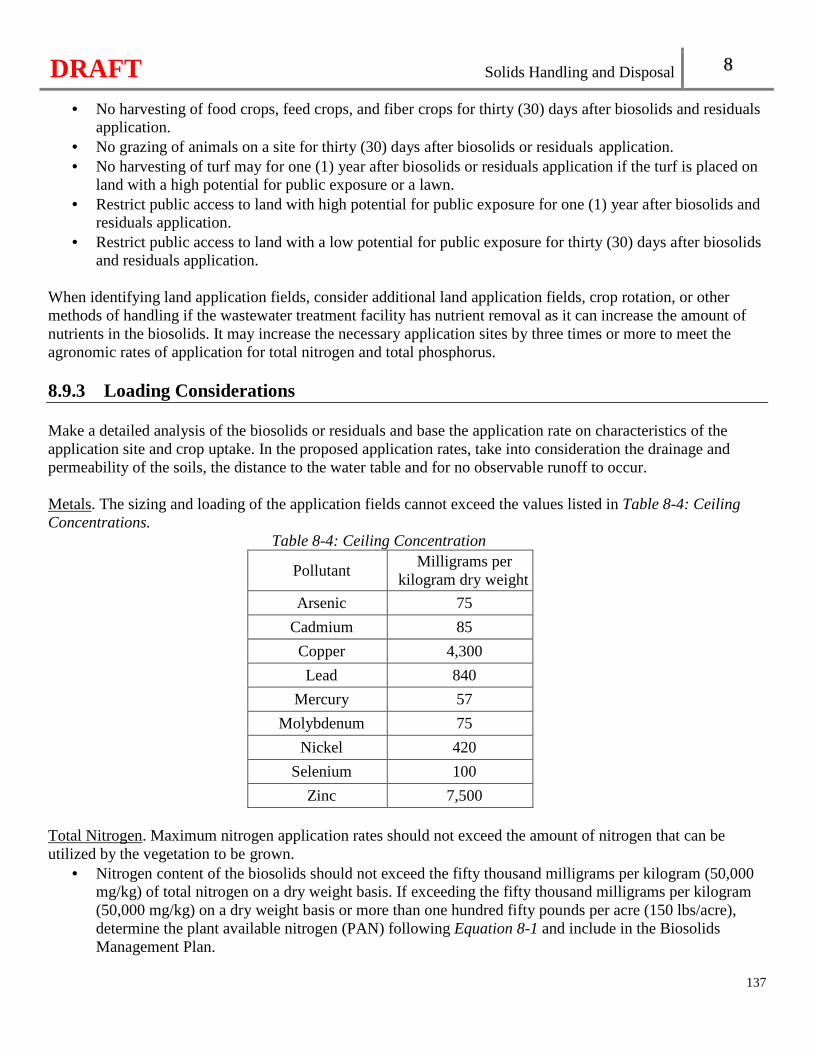
DRAFT Solids Handling and Disposal 8
137
• No harvesting of food crops, feed crops, and fiber crops for thirty (30) days after biosolids and residuals application.
• No grazing of animals on a site for thirty (30) days after biosolids or residuals application. • No harvesting of turf may for one (1) year after biosolids or residuals application if the turf is placed on
land with a high potential for public exposure or a lawn. • Restrict public access to land with high potential for public exposure for one (1) year after biosolids and
residuals application. • Restrict public access to land with a low potential for public exposure for thirty (30) days after biosolids
and residuals application. When identifying land application fields, consider additional land application fields, crop rotation, or other methods of handling if the wastewater treatment facility has nutrient removal as it can increase the amount of nutrients in the biosolids. It may increase the necessary application sites by three times or more to meet the agronomic rates of application for total nitrogen and total phosphorus. 8.9.3 Loading Considerations Make a detailed analysis of the biosolids or residuals and base the application rate on characteristics of the application site and crop uptake. In the proposed application rates, take into consideration the drainage and permeability of the soils, the distance to the water table and for no observable runoff to occur. Metals. The sizing and loading of the application fields cannot exceed the values listed in Table 8-4: Ceiling Concentrations.
Table 8-4: Ceiling Concentration
Pollutant Milligrams per
kilogram dry weight
Arsenic 75
Cadmium 85
Copper 4,300
Lead 840
Mercury 57
Molybdenum 75
Nickel 420
Selenium 100
Zinc 7,500 Total Nitrogen. Maximum nitrogen application rates should not exceed the amount of nitrogen that can be utilized by the vegetation to be grown.
• Nitrogen content of the biosolids should not exceed the fifty thousand milligrams per kilogram (50,000 mg/kg) of total nitrogen on a dry weight basis. If exceeding the fifty thousand milligrams per kilogram (50,000 mg/kg) on a dry weight basis or more than one hundred fifty pounds per acre (150 lbs/acre), determine the plant available nitrogen (PAN) following Equation 8-1 and include in the Biosolids Management Plan.
DRAFT Solids Handling and Disposal 8
138
Equation 8-1 PAN=(Nitrate + nitrite nitrogen) + (organic nitrogen x 0.2) + (ammonia nitrogen x volatilization factor) The volatilization factors are 0.7 for surface application and 1 for subsurface injection.
Total Phosphorus. Phosphorus can be present at levels that exceed the crop needs when applications are based on nitrogen, therefore perform an agronomic soil test as not all of that P is available for crop growth. Phosphorus tests include the Mehlich-3 soil test, the Bray-1 and the Olson P tests. Application of biosolids is limited to one hundred eighty pounds (180 lbs) of available phosphorus based on the Bray P-1 test. If wanting to apply more than one hundred eighty pounds (180 lbs), include the expected total phosphorus loading for approval in the Biosolids Management Plan. 8.9.4 Operations and Maintenance Considerations Include an operations and maintenance section in the facility’s Biosolids Management Plan or a separate document and have it available. Update the operations and maintenance sections as additional fields are added for application or there is a change in the method of application. The operations and maintenance section should: Contain operation and maintenance information on each piece of equipment used on the application site, including any pumps, piping, traveling guns, knifing operations. Contain contact information for each land application field, including owner’s name, address, and phone number. Cover the spreading operation. Considerations for the spreading operations may include:
• Hauling equipment. Design the biosolids hauling equipment to prevent spillage, odor and other public nuisance. Soil compaction should be avoided because compaction restricts plant root growth, which in turn limits plant top growth.
• Valve control. Provide the spreading tank truck with a control so that the discharge valve can be opened and closed by the driver while the vehicle is in motion. The spreading valve should be of the fail-safe type (that is, self-closing) or an additional manual standby valve should be employed to prevent uncontrolled spreading or spillage.
• Application. Consideration for immediate incorporation of biosolids after spreading or subsurface injection to reduce odors and runoff. When such method is utilized, consider an adjustment to account for the reduced rate of ammonia loss into the atmosphere in the computation for nitrogen balance.
Include Emergency Operations. Identified emergency operations should include additional fields available for land application or the process the permittee will undertake to obtain additional fields or if the permittee will not land apply. If not land applying the biosolids, the Plan should identify who is willing to accept the biosolids, whether another wastewater treatment facility or a municipal landfill.

DRAFT Solids Handling and Disposal 8
139
8.10 Other Sludge or Biosolids Disposal Methods When other sludge disposal methods, such as incineration and landfill, are considered, contact the Department, including the Air Pollution Program and the Solid Waste Management Program to ensure all applicable regulations are followed.

DRAFT
140
DRAFT Biological Treatment 9
Chapter 9: Biological Treatment
141
9.1 Septic Tanks Septic tanks may be accepted as a satisfactory means of primary treatment for wastewater treatment facilities with a design average flow of twenty-two thousand five hundred (22,500) gallons per day or less. Septic tanks may be utilized in the design as a preliminary treatment technology before a recirculating media filter, irrigation system, or dispersal system.
9.1.1 Size The capacity of the septic tank should be determined based on the design average flow of the facility with a thirty-six (36)-hour detention time at a minimum. A septic tank must have a minimum capacity of at least one thousand (1,000) gallons [See 10 CSR 20-8.180(2)(A)]. Provide twenty percent (20%) of the septic tank volume freeboard and ventilation. 9.1.2 Construction Materials Septic tanks are typically constructed from fiberglass reinforced polyester, high density polyethylene, or concrete. Utilize corrosive resistant materials for all pipes and appurtenances within a septic tank. Austenitic stainless steel of type 316 or 304 is standard for metal components. Nylon is degraded by hydrogen sulfide and is not acceptable. Avoid contact between dissimilar metals or make other provisions to minimize galvanic action. 9.1.3 Watertight Septic tanks are watertight. 9.1.4 Access Provide access for service by a minimum access diameter of twenty-four inches (24") with bolt-down cover assemblies or with locked covers. 9.1.5 Baffles The septic tank shall be baffled [See 10 CSR 20-8.180(2)(B)]. Install baffle walls with a minimum three inch (3") air gap from the lid of the septic tank for ventilation. 9.1.6 Inlet and Outlet Tees Provide inlet and outlet tees to maximize removal and retention of solids within the septic tank.
DRAFT Biological Treatment 9
142
9.1.7 Ventilation Ventilate septic tanks. 9.1.8 Outlet Screen Install an effluent screen on the septic tank outlet to retain large solids. 9.1.9 Location Bury septic tanks with access risers at or above grade. Consider accessibility for future maintenance and removal of accumulated solids.
9.2 Recirculating Media Filters Recirculating media filters are generally considered suitable for treatment of design average flows less than one hundred thousand gallons per day (100,000 gpd) or for flows which are highly intermittent or seasonal. 9.2.1 Location Recirculating media filters following primary treat ment shall be located a minimum of two hundred feet (200') from future or existing residences or other establishments [See 10 CSR 20-8.180(3)(A)]. Consider access needed for maintenance and repairs by construction equipment. Consider the possibility of intermittent objectionable odors occurring during dosing when locating these systems. 9.2.2 Primary Treatment Provide primary treatment prior to all forms of recirculating media filtration to prevent fouling of the filter from suspended solids, grease, and from excessive bacterial growth due to biochemical oxygen demand (BOD) overloading. This can be accomplished by providing a quiescent environment to promote settling of suspended particles, as well as allowing for contact between the influent wastewater and naturally occurring anaerobic bacteria. If the wastewater is domestic in origin, settleable and floatable solid separation by a properly sized two-compartment septic tank with effluent baffle screening, or equivalent wastewater sedimentation/initial treatment unit, will suffice. The septic tank design is expected to provide a minimum of thirty percent (30%) removal of BOD loading. 9.2.3 Equalization Tank Determine the size of the equalization tank through a hydraulic analysis of the system that distributes the compressed flow over a twenty to twenty-four hour (20 to 24) time period and eliminates surcharging of the sand filter. Provide flow equalization when the total daily flow occurs over a period of twelve hours or less and the filter is sized based on a hydraulic analysis of hourly flows. Size the equalization tank for half the total daily flow. The equalization tank mixture is pumped to the recirculation tank at a rate that equalizes total flow over a
DRAFT Biological Treatment 9
143
twenty-four (24) hour period. Operate the pumps in the equalization tank using a timer with a high-level override control. 9.2.4 Filter Bed A minimum of two (2) filter beds and a diversion box are required for all design flows [See 10 CSR 20-8.180(3)(B)]. Where two (2) filter beds are used, size each for the design average flow. Install filter bottoms with a minimum geomembrane liner thickness of twenty millimeters (20 mm) or poured reinforced concrete. Install concrete or geomembrane liner filter walls that extend at least six inches (6") above the top of the media bed and at least six inches (6") above the adjacent ground surface. Berms or diversion ditches may be necessary to divert runoff from entering the filter. Filters may be covered to protect against severe weather conditions and to avoid encroachment of weeds or animals. The cover also serves to reduce odor conditions. Allow a space of twelve to twenty-four inches (12–24") between the insulated cover and sand surface. Construct covers of treated wooden planks, galvanized metal or other suitable materials. Screens or hardware cloth mounted on wooden frames may also serve to protect filter surfaces. Where weather conditions dictate, insulate covers. Design the filter manifold with a minimum five foot (5') pressure residual at the most remote orifice, or no more than a ten percent (10%) differential in flow between any two (2) orifices. Include a flushing valve enclosed in a valve box installed at grade at the distal end of each distribution pipe. Include provisions to allow for cleaning the distribution lines with a bottle washer and plumber's snake. 9.2.5 Dosing Base daily dose frequencies on media grain size, wastewater strength and operating temperatures. Dosing of the filter should provide for flooding the bed to a depth of approximately two inches (2") or one and one-fourth gallons per square foot (1.25 gal/ft2). Set the on cycle so that the orifice discharge per dose cycle does not exceed two (2) gallons per orifice. Both timer and float switch controls are required; timers are the primary method of operation and the float switch control is a back-up [See 10 CSR 20-8.180(3)(C)]. Provide adjustable timers so that dosing schedules can be modified as site conditions warrant. Proper sizing of the recirculation tank should minimize float switch operation. 9.2.6 Loading Hydraulic Loading. The hydraulic loading for media filters shall be less than three and half gallons per day per square foot (3.5 gpd/ft2) [See 10 CSR 20-8.180(3)(D)]. In choosing what loading rate to use, consider the effective size of the media and maintenance needs.
DRAFT Biological Treatment 9
144
Organic Loading. The organic loading rate should be less than 0.003 pounds of applied BOD per square foot per day. Proper design for systems designed to nitrify and reduce nitrogen necessitates determining the alkalinity of the influent. If the alkalinity is low, provide a method for adding and monitoring alkalinity to the system. Approximately eight milligrams (8 mg) of alkalinity are consumed for every milligram of ammonia oxidized. Design to maintain a residual alkalinity. 9.2.7 Media Characteristics The media is any of a number of physical structures whose sole purpose is to provide a surface to support biological growth. Commonly used media includes rock, gravel, and sand of various sizes, textile media, and peat. Finely crushed limestone, dolomite, slag, any clay, limestone or appreciable amounts of organic material is not acceptable [See 10 CSR 20-8.180(3)(E)]. Rock, sand and gravel media, when used–
• Shall be a total of at least thirty-three inches (33") deep [See 10 CSR 20-8.180(3)(E)1.A.]; • Shall have at least twenty-four inches (24") of fine filtering media[See 10 CSR 20-8.180(3)(E)1.B.]; • Use a coarser material below the fine filtering media with a depth great enough to cover the under drain
pipes, so where four inch (4") diameter under drains are used, a lower coarse media depth of six inches (6") is sufficient;
• Place an intermediate layer of three inches (3") between the coarse and fine media to prevent migration of fine media into the lower layer;
• The uniformity coefficient should be less than 2.5 and not exceed 3.5; • Effective Size: 3 mm to 5 mm; and • See Table 9-1 for particle size distribution.
Table 9-1 Particle Size Distribution:
Sieve Particle Size Percent Passing by Weight 3/8 inch 9.50 mm 100% No. 4 4.75 mm 0 to 95% No. 8 2.36 mm 0 to 2% No. 30 0.60 mm 0 to 0.1%
Synthetic media will be reviewed on a case-by-case basis per the manufacturer’s specifications. 9.2.8 Recirculation Wastewater which has been treated in the recirculating media filter, collects at the bottom of the filter through an underdrain and a portion is returned to the recirculating/mixing tank. Split the underdrain flow to direct at least seventy-five to eighty-five percent (75-85%) of the treated wastewater back to the recirculating/mixing tank. Provide a recirculation ratio of five to one (5:1), but no less than three to one (3:1).
DRAFT Biological Treatment 9
145
To encourage mixing of fresh influent with partially treated recirculating return filtrate, the return line from the filter should enter the recirculating/mixing tank at the same end of the tank as the influent from the septic tank and at the opposite end from the recirculating pump. Return the partially treated recirculating return filtrate to the septic tank to encourage denitrification. Wire float switches in parallel with the timer to control the pump during periods of excessive wastewater flows, and in event of timer malfunction. Install a redundant off/low level alarm in accordance with the pump manufacturer’s recommendations to assure adequate pump submergence in the event of low levels in the recirculating/mixing tank. 9.2.9 Underdrain Systems Collect filtrate and discharge from the bottom of the sand filter by either a gravity flow underdrain system or a pumped system. A single pipe in the middle of the filter is unacceptable as an underdrain. Size piping to allow for the rapid return of the filtrate to the recirculation and equalization tanks to prevent ponding in the filter. Underdrain systems are slotted poly vinyl chloride (PVC) or high density polyethylene (HDPE) pipes or chamber. Include a minimum of two (2) underdrain pipes in each filter section. Place the pipes upon the impervious liner at the bottom of the filter with the slots facing upward. Bring the distal end of the underdrain to grade and cover with a removable cap housed in a protective chamber. Install the underdrain pipe at a half to one percent (0.5-1.0%) grade and connect it to a manifold outside the filter. Space underdrain pipes a maximum of eight feet (8') on center. 9.2.10 Distribution Systems Distribution is often provided through pipelines and directed on splash plates located at the center or corners of the sand surface. Occasionally, spray nozzles are employed as well and ridge and furrow application has been successful during winter operation. Place distribution lateral lines two foot (2') apart. Install removable endcaps at the ends of the laterals to facilitate ease of cleaning and flushing. Size lateral lines one to one and a quarter inches (1.0-1.25") with a maximum length of seventy-five feet (75'). The Hazen Williams C factor should be between one hundred forty and one hundred fifty (140-150). Place the orifices on the lateral lines where drainage can occur during freezing weather. Use orifice shields to prevent clogging. Evenly distribute the system so that the maximum lateral travel over the sand is not more than twenty feet (20').
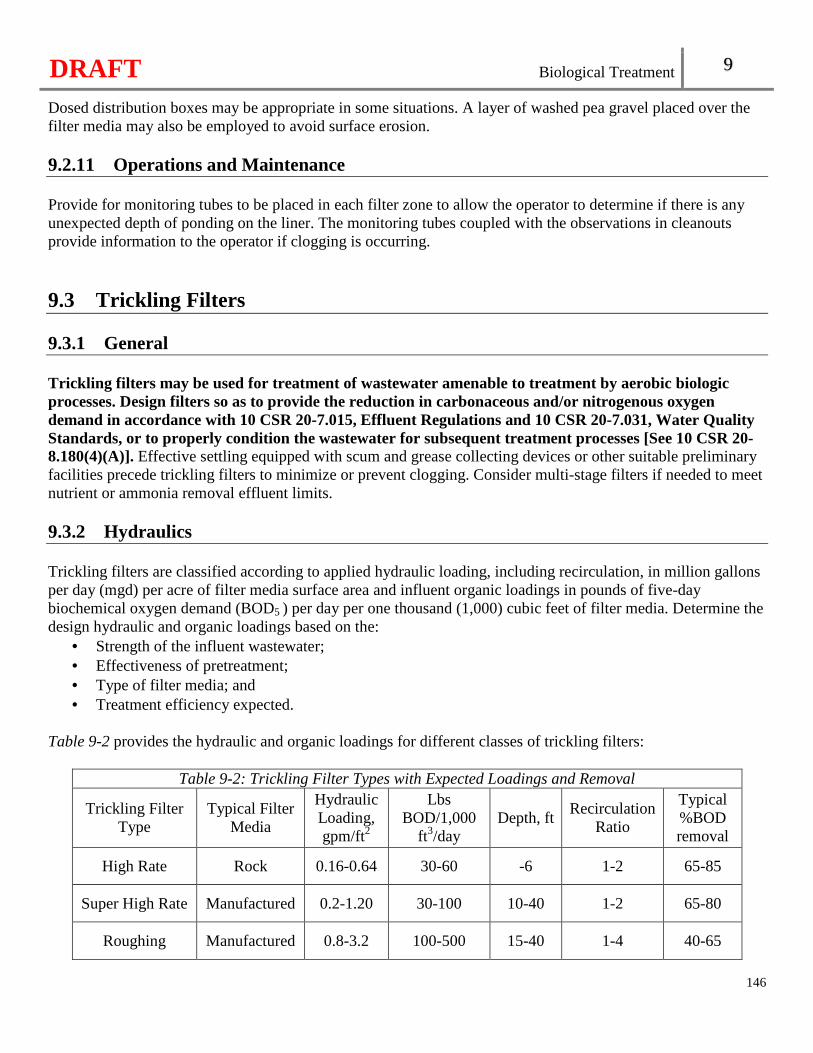
DRAFT Biological Treatment 9
146
Dosed distribution boxes may be appropriate in some situations. A layer of washed pea gravel placed over the filter media may also be employed to avoid surface erosion. 9.2.11 Operations and Maintenance Provide for monitoring tubes to be placed in each filter zone to allow the operator to determine if there is any unexpected depth of ponding on the liner. The monitoring tubes coupled with the observations in cleanouts provide information to the operator if clogging is occurring.
9.3 Trickling Filters 9.3.1 General Trickling filters may be used for treatment of wastewater amenable to treatment by aerobic biologic processes. Design filters so as to provide the reduction in carbonaceous and/or nitrogenous oxygen demand in accordance with 10 CSR 20-7.015, Effluent Regulations and 10 CSR 20-7.031, Water Quality Standards, or to properly condition the wastewater for subsequent treatment processes [See 10 CSR 20-8.180(4)(A)]. Effective settling equipped with scum and grease collecting devices or other suitable preliminary facilities precede trickling filters to minimize or prevent clogging. Consider multi-stage filters if needed to meet nutrient or ammonia removal effluent limits. 9.3.2 Hydraulics Trickling filters are classified according to applied hydraulic loading, including recirculation, in million gallons per day (mgd) per acre of filter media surface area and influent organic loadings in pounds of five-day biochemical oxygen demand (BOD5 ) per day per one thousand (1,000) cubic feet of filter media. Determine the design hydraulic and organic loadings based on the:
• Strength of the influent wastewater; • Effectiveness of pretreatment; • Type of filter media; and • Treatment efficiency expected.
Table 9-2 provides the hydraulic and organic loadings for different classes of trickling filters:
Table 9-2: Trickling Filter Types with Expected Loadings and Removal
Trickling Filter Type
Typical Filter Media
Hydraulic Loading, gpm/ft2
Lbs BOD/1,000
ft3/day Depth, ft
Recirculation Ratio
Typical %BOD removal
High Rate Rock 0.16-0.64 30-60 -6 1-2 65-85
Super High Rate Manufactured 0.2-1.20 30-100 10-40 1-2 65-80
Roughing Manufactured 0.8-3.2 100-500 15-40 1-4 40-65
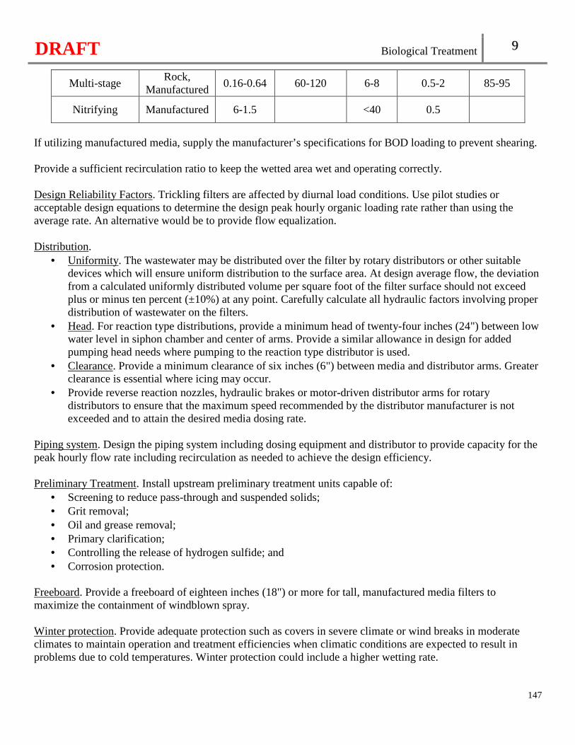
DRAFT Biological Treatment 9
147
Multi-stage Rock,
Manufactured 0.16-0.64 60-120 6-8 0.5-2 85-95
Nitrifying Manufactured 6-1.5 <40 0.5
If utilizing manufactured media, supply the manufacturer’s specifications for BOD loading to prevent shearing. Provide a sufficient recirculation ratio to keep the wetted area wet and operating correctly. Design Reliability Factors. Trickling filters are affected by diurnal load conditions. Use pilot studies or acceptable design equations to determine the design peak hourly organic loading rate rather than using the average rate. An alternative would be to provide flow equalization. Distribution.
• Uniformity. The wastewater may be distributed over the filter by rotary distributors or other suitable devices which will ensure uniform distribution to the surface area. At design average flow, the deviation from a calculated uniformly distributed volume per square foot of the filter surface should not exceed plus or minus ten percent (±10%) at any point. Carefully calculate all hydraulic factors involving proper distribution of wastewater on the filters.
• Head. For reaction type distributions, provide a minimum head of twenty-four inches (24") between low water level in siphon chamber and center of arms. Provide a similar allowance in design for added pumping head needs where pumping to the reaction type distributor is used.
• Clearance. Provide a minimum clearance of six inches (6") between media and distributor arms. Greater clearance is essential where icing may occur.
• Provide reverse reaction nozzles, hydraulic brakes or motor-driven distributor arms for rotary distributors to ensure that the maximum speed recommended by the distributor manufacturer is not exceeded and to attain the desired media dosing rate.
Piping system. Design the piping system including dosing equipment and distributor to provide capacity for the peak hourly flow rate including recirculation as needed to achieve the design efficiency. Preliminary Treatment. Install upstream preliminary treatment units capable of:
• Screening to reduce pass-through and suspended solids; • Grit removal; • Oil and grease removal; • Primary clarification; • Controlling the release of hydrogen sulfide; and • Corrosion protection.
Freeboard. Provide a freeboard of eighteen inches (18") or more for tall, manufactured media filters to maximize the containment of windblown spray. Winter protection. Provide adequate protection such as covers in severe climate or wind breaks in moderate climates to maintain operation and treatment efficiencies when climatic conditions are expected to result in problems due to cold temperatures. Winter protection could include a higher wetting rate.
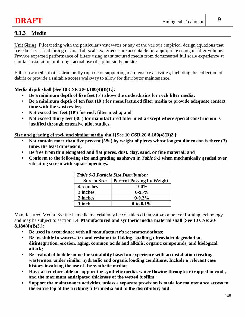
DRAFT Biological Treatment 9
148
9.3.3 Media Unit Sizing. Pilot testing with the particular wastewater or any of the various empirical design equations that have been verified through actual full scale experience are acceptable for appropriate sizing of filter volume. Provide expected performance of filters using manufactured media from documented full scale experience at similar installation or through actual use of a pilot study on-site. Either use media that is structurally capable of supporting maintenance activities, including the collection of debris or provide a suitable access walkway to allow for distributor maintenance. Media depth shall [See 10 CSR 20-8.180(4)(B)1.]:
• Be a minimum depth of five feet (5’) above the underdrains for rock filter media; • Be a minimum depth of ten feet (10’) for manufactured filter media to provide adequate contact
time with the wastewater; • Not exceed ten feet (10') for rock filter media; and • Not exceed thirty feet (30') for manufactured filter media except where special construction is
justified through extensive pilot studies. Size and grading of rock and similar media shall [See 10 CSR 20-8.180(4)(B)2.]:
• Not contain more than five percent (5%) by weight of pieces whose longest dimension is three (3) times the least dimension;
• Be free from thin elongated and flat pieces, dust, clay, sand, or fine material; and • Conform to the following size and grading as shown in Table 9-3 when mechanically graded over
vibrating screen with square openings.
Table 9-3 Particle Size Distribution: Screen Size Percent Passing by Weight
4.5 inches 100% 3 inches 0-95% 2 inches 0-0.2% 1 inch 0 to 0.1%
Manufactured Media. Synthetic media material may be considered innovative or nonconforming technology and may be subject to section 1.4. Manufactured and synthetic media material shall [See 10 CSR 20-8.180(4)(B)3.]:
• Be used in accordance with all manufacturer's recommendations; • Be insoluble in wastewater and resistant to flaking, spalling, ultraviolet degradation,
disintegration, erosion, aging, common acids and alkalis, organic compounds, and biological attack;
• Be evaluated to determine the suitability based on experience with an installation treating wastewater under similar hydraulic and organic loading conditions. Include a relevant case history involving the use of the synthetic media;
• Have a structure able to support the synthetic media, water flowing through or trapped in voids, and the maximum anticipated thickness of the wetted biofilm;
• Support the maintenance activities, unless a separate provision is made for maintenance access to the entire top of the trickling filter media and to the distributor; and
DRAFT Biological Treatment 9
149
• Be placed with the edges matched as nearly as possible to provide consistent hydraulic conditions within the trickling filter.
Handling and placing of media. Store material delivered to the filter site on wood planks or other approved clean hard surfaced areas. Re-handle all material at the filter site and do not dump material directly into the filter.
• Wash and rescreen or fork crushed rock and similar media at the filter site to remove all fines. • Place the material by hand to a depth of twelve inches (12") above the tile underdrains and the
remainder of material may be placed by means of belt conveyors or equally effective methods approved by the engineer.
• Carefully place all material so as not to damage the underdrains. • Specify handling and placing of manufactured media.
9.3.4 Underdrainage System Arrangement. Provide underdrains with semicircular inverts or equivalent that cover the entire floor of the filter. The unsubmerged gross combined area of the inlet openings into the underdrain should be at least fifteen percent (15%) of the surface area of the filter. Hydraulic capacity. The underdrains shall be designed with [See 10 CSR 20-8.180(4)(C)1.]:
• A minimum slope of one percent (1%); • Effluent channels that produce a minimum velocity of two feet per second (2 fps) at average daily
rate of application to the filter; • The underdrainage system, effluent channels and effluent pipe to permit free passage of air; • The size of drains, channels, and pipe so that not more than fifty percent (50%) of their cross
section area will be submerged under the design peak hydraulic loading, including proposed or possible future or recirculated flows; and
• Consideration for the use of forced ventilation, particularly for covered filters and deep manufactured media filters.
Flushing. Provision should be made for flushing the underdrains. In small filters, use of a peripheral head channel with vertical vents is acceptable for flushing purposes. Inspection facilities should be provided. 9.3.5 Filter Dosing Use suitable flow characteristics for the application of wastewater to a filter by siphon, pump, or gravity discharge from preceding treatment unit. Design to control instantaneous dosing rates under both normal operating conditions and filter-flushing conditions. Design so the distributor speed and the recirculation rate can be adjusted for the dosing intensity as a compensatory measure under low-flow conditions. Table 9-4 provides design ranges of dosing intensity for normal usage periods and for flushing periods.
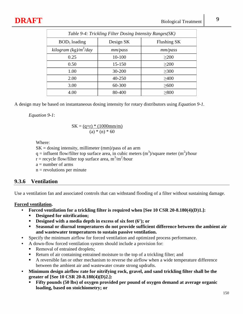
DRAFT Biological Treatment 9
150
Table 9-4: Trickling Filter Dosing Intensity Ranges(SK)
BOD5 loading Design SK Flushing SK
kilogram (kg)/m3/day mm/pass mm/pass
0.25 10-100 ≥200
0.50 15-150 ≥200
1.00 30-200 ≥300
2.00 40-250 ≥400
3.00 60-300 ≥600
4.00 80-400 ≥800 A design may be based on instantaneous dosing intensity for rotary distributors using Equation 9-1.
Equation 9-1:
SK = (q+r) * (1000mm/m) (a) * (n) * 60
Where: SK = dosing intensity, millimeter (mm)/pass of an arm q = influent flow/filter top surface area, in cubic meters (m3)/square meter (m2)/hour r = recycle flow/filter top surface area, m3/m2/hour a = number of arms n = revolutions per minute
9.3.6 Ventilation Use a ventilation fan and associated controls that can withstand flooding of a filter without sustaining damage. Forced ventilation.
• Forced ventilation for a trickling filter is requir ed when [See 10 CSR 20-8.180(4)(D)1.]: � Designed for nitrification; � Designed with a media depth in excess of six feet (6’); or � Seasonal or diurnal temperatures do not provide sufficient difference between the ambient air
and wastewater temperatures to sustain passive ventilation. • Specify the minimum airflow for forced ventilation and optimized process performance. • A down-flow forced ventilation system should include a provision for:
� Removal of entrained droplets; � Return of air containing entrained moisture to the top of a trickling filter; and � A reversible fan or other mechanism to reverse the airflow when a wide temperature difference
between the ambient air and wastewater create strong updrafts. • Minimum design airflow rate for nitrifying rock, gr avel, and sand trickling filter shall be the
greater of [See 10 CSR 20-8.180(4)(D)2.]: � Fifty pounds (50 lbs) of oxygen provided per pound of oxygen demand at average organic
loading, based on stoichiometry; or
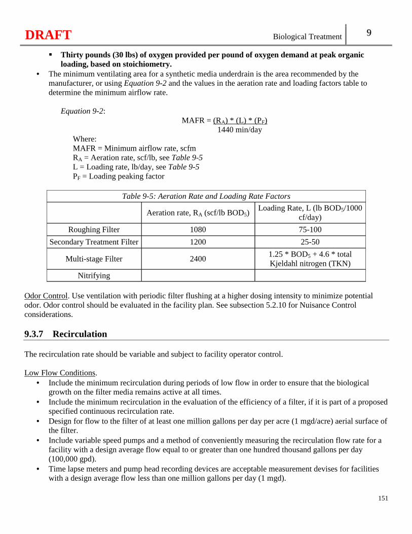
DRAFT Biological Treatment 9
151
� Thirty pounds (30 lbs) of oxygen provided per pound of oxygen demand at peak organic loading, based on stoichiometry.
• The minimum ventilating area for a synthetic media underdrain is the area recommended by the manufacturer, or using Equation 9-2 and the values in the aeration rate and loading factors table to determine the minimum airflow rate.
Equation 9-2:
MAFR = (RA) * (L) * (PF) 1440 min/day
Where: MAFR = Minimum airflow rate, scfm RA = Aeration rate, scf/lb, see Table 9-5 L = Loading rate, lb/day, see Table 9-5 PF = Loading peaking factor
Table 9-5: Aeration Rate and Loading Rate Factors
Aeration rate, RA (scf/lb BOD5) Loading Rate, L (lb BOD5/1000
cf/day)
Roughing Filter 1080 75-100
Secondary Treatment Filter 1200 25-50
Multi-stage Filter 2400 1.25 * BOD5 + 4.6 * total Kjeldahl nitrogen (TKN)
Nitrifying Odor Control. Use ventilation with periodic filter flushing at a higher dosing intensity to minimize potential odor. Odor control should be evaluated in the facility plan. See subsection 5.2.10 for Nuisance Control considerations. 9.3.7 Recirculation The recirculation rate should be variable and subject to facility operator control. Low Flow Conditions.
• Include the minimum recirculation during periods of low flow in order to ensure that the biological growth on the filter media remains active at all times.
• Include the minimum recirculation in the evaluation of the efficiency of a filter, if it is part of a proposed specified continuous recirculation rate.
• Design for flow to the filter of at least one million gallons per day per acre (1 mgd/acre) aerial surface of the filter.
• Include variable speed pumps and a method of conveniently measuring the recirculation flow rate for a facility with a design average flow equal to or greater than one hundred thousand gallons per day (100,000 gpd).
• Time lapse meters and pump head recording devices are acceptable measurement devises for facilities with a design average flow less than one million gallons per day (1 mgd).
DRAFT Biological Treatment 9
152
9.3.8 Distribution Equipment Provide a rotary, horizontal, or traveling distribution system that distributes wastewater uniformly over the entire surface of a filter at the design and flushing dosing intensities. Include filter distributors that operate properly at all anticipated flow rates. Provide equipment that will not deviate from the design dosing intensity by more than ten percent (10%). Include electrically driven, variable speed filter distributor to allow operation at optimum dosing intensity independent of recirculation pumping. Include filter distributors with cleanout gates on the ends of the arms and an end spray nozzle to wet the edge of the media. Extend the filter walls at least twelve inches (12") above the distributor arms. The minimum clearance between the top of the filter media and the distributing nozzles is six inches (6"). Rotary distributors should be capable of operating at speeds as low as one revolution per thirty minutes (1rev/30 mins). 9.3.9 Hydraulics Design the trickling system to hydraulically accommodate the specified flushing hydraulic dosing intensity and facilitate cleaning and rodding of the distributor arms. 9.3.10 Sloughed Biomass Design the trickling filter system to prevent recirculation of sloughed biomass in pieces larger than the distributor nozzle opening or the filter media voids. 9.3.11 Nuisance Organism Control Operate trickling filters at proper design dosing intensities, with periodic flushing at higher dosing intensities and minimize areas where sludge may accumulate to control nuisance organisms, including filter flies and snails.
9.4 Activated Sludge 9.4.1 General Applicability.
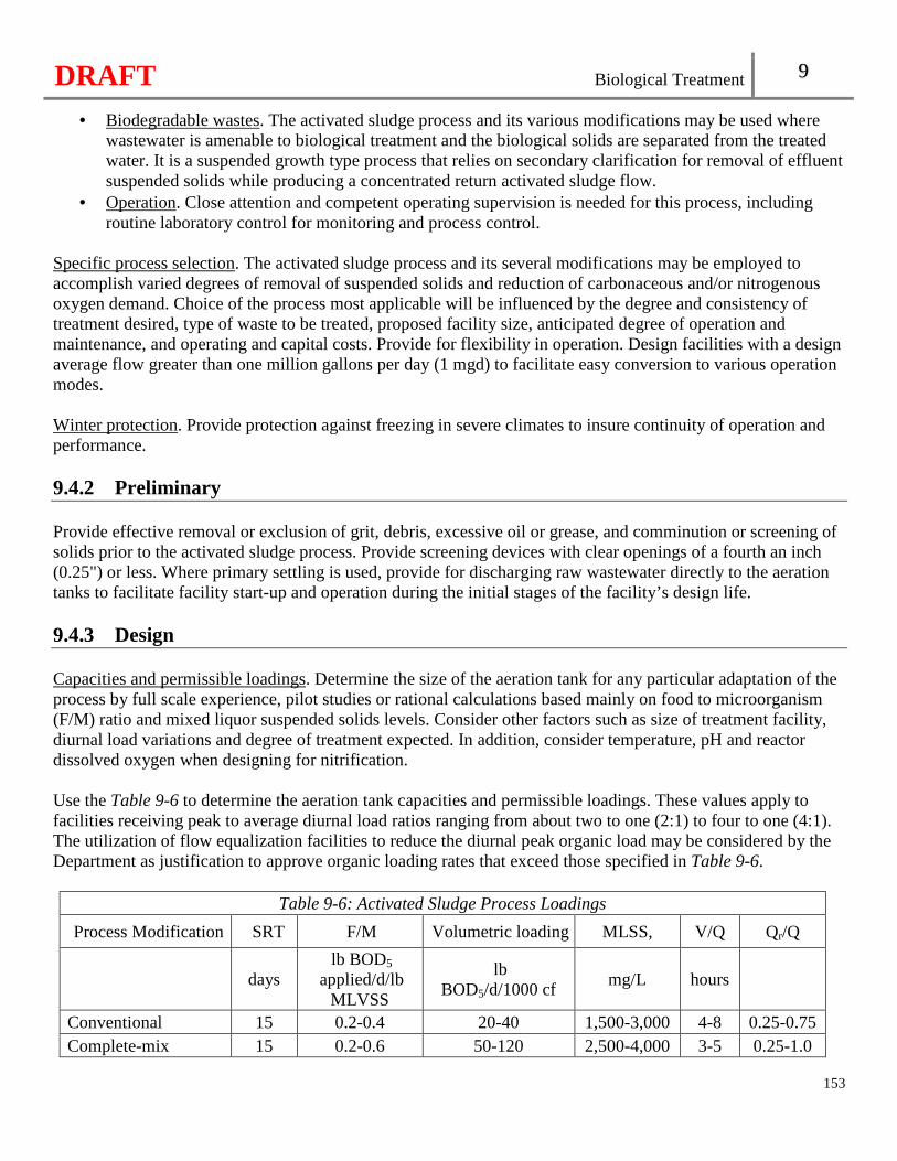
DRAFT Biological Treatment 9
153
• Biodegradable wastes. The activated sludge process and its various modifications may be used where wastewater is amenable to biological treatment and the biological solids are separated from the treated water. It is a suspended growth type process that relies on secondary clarification for removal of effluent suspended solids while producing a concentrated return activated sludge flow.
• Operation. Close attention and competent operating supervision is needed for this process, including routine laboratory control for monitoring and process control.
Specific process selection. The activated sludge process and its several modifications may be employed to accomplish varied degrees of removal of suspended solids and reduction of carbonaceous and/or nitrogenous oxygen demand. Choice of the process most applicable will be influenced by the degree and consistency of treatment desired, type of waste to be treated, proposed facility size, anticipated degree of operation and maintenance, and operating and capital costs. Provide for flexibility in operation. Design facilities with a design average flow greater than one million gallons per day (1 mgd) to facilitate easy conversion to various operation modes. Winter protection. Provide protection against freezing in severe climates to insure continuity of operation and performance. 9.4.2 Preliminary Provide effective removal or exclusion of grit, debris, excessive oil or grease, and comminution or screening of solids prior to the activated sludge process. Provide screening devices with clear openings of a fourth an inch (0.25") or less. Where primary settling is used, provide for discharging raw wastewater directly to the aeration tanks to facilitate facility start-up and operation during the initial stages of the facility’s design life. 9.4.3 Design Capacities and permissible loadings. Determine the size of the aeration tank for any particular adaptation of the process by full scale experience, pilot studies or rational calculations based mainly on food to microorganism (F/M) ratio and mixed liquor suspended solids levels. Consider other factors such as size of treatment facility, diurnal load variations and degree of treatment expected. In addition, consider temperature, pH and reactor dissolved oxygen when designing for nitrification. Use the Table 9-6 to determine the aeration tank capacities and permissible loadings. These values apply to facilities receiving peak to average diurnal load ratios ranging from about two to one (2:1) to four to one (4:1). The utilization of flow equalization facilities to reduce the diurnal peak organic load may be considered by the Department as justification to approve organic loading rates that exceed those specified in Table 9-6.
Table 9-6: Activated Sludge Process Loadings
Process Modification SRT F/M Volumetric loading MLSS, V/Q Qr/Q
days lb BOD5
applied/d/lb MLVSS
lb BOD5/d/1000 cf
mg/L hours
Conventional 15 0.2-0.4 20-40 1,500-3,000 4-8 0.25-0.75 Complete-mix 15 0.2-0.6 50-120 2,500-4,000 3-5 0.25-1.0
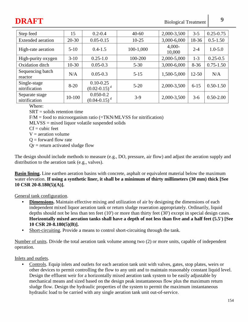
DRAFT Biological Treatment 9
154
Step feed 15 0.2-0.4 40-60 2,000-3,500 3-5 0.25-0.75 Extended aeration 20-30 0.05-0.15 10-25 3,000-6,000 18-36 0.5-1.50
High-rate aeration 5-10 0.4-1.5 100-1,000 4,000-10,000
2-4 1.0-5.0
High-purity oxygen 3-10 0.25-1.0 100-200 2,000-5,000 1-3 0.25-0.5 Oxidation ditch 10-30 0.05-0.3 5-30 3,000-6,000 8-36 0.75-1.50 Sequencing batch reactor
N/A 0.05-0.3 5-15 1,500-5,000 12-50 N/A
Single-stage nitrification
8-20 0.10-0.25
(0.02-0.15) d 5-20 2,000-3,500 6-15 0.50-1.50
Separate stage nitrification
10-100 0.050-0.2
(0.04-0.15) d 3-9 2,000-3,500 3-6 0.50-2.00
Where: SRT = solids retention time F/M = food to microorganism ratio (=TKN/MLVSS for nitrification) MLVSS = mixed liquor volatile suspended solids Cf = cubic feet V = aeration volume Q = forward flow rate Qr = return activated sludge flow
The design should include methods to measure (e.g., DO, pressure, air flow) and adjust the aeration supply and distribution to the aeration tank (e.g., valves). Basin lining. Line earthen aeration basins with concrete, asphalt or equivalent material below the maximum water elevation. If using a synthetic liner, it shall be a minimum of thirty millimeters (30 mm) thick [See 10 CSR 20-8.180(5)(A)]. General tank configuration.
• Dimensions. Maintain effective mixing and utilization of air by designing the dimensions of each independent mixed liquor aeration tank or return sludge reaeration appropriately. Ordinarily, liquid depths should not be less than ten feet (10') or more than thirty feet (30') except in special design cases. Horizontally mixed aeration tanks shall have a depth of not less than five and a half feet (5.5') [See 10 CSR 20-8.180(5)(B)].
• Short-circuiting. Provide a means to control short-circuiting through the tank. Number of units. Divide the total aeration tank volume among two (2) or more units, capable of independent operation. Inlets and outlets.
• Controls. Equip inlets and outlets for each aeration tank unit with valves, gates, stop plates, weirs or other devices to permit controlling the flow to any unit and to maintain reasonably constant liquid level. Design the effluent weir for a horizontally mixed aeration tank system to be easily adjustable by mechanical means and sized based on the design peak instantaneous flow plus the maximum return sludge flow. Design the hydraulic properties of the system to permit the maximum instantaneous hydraulic load to be carried with any single aeration tank unit out-of-service.
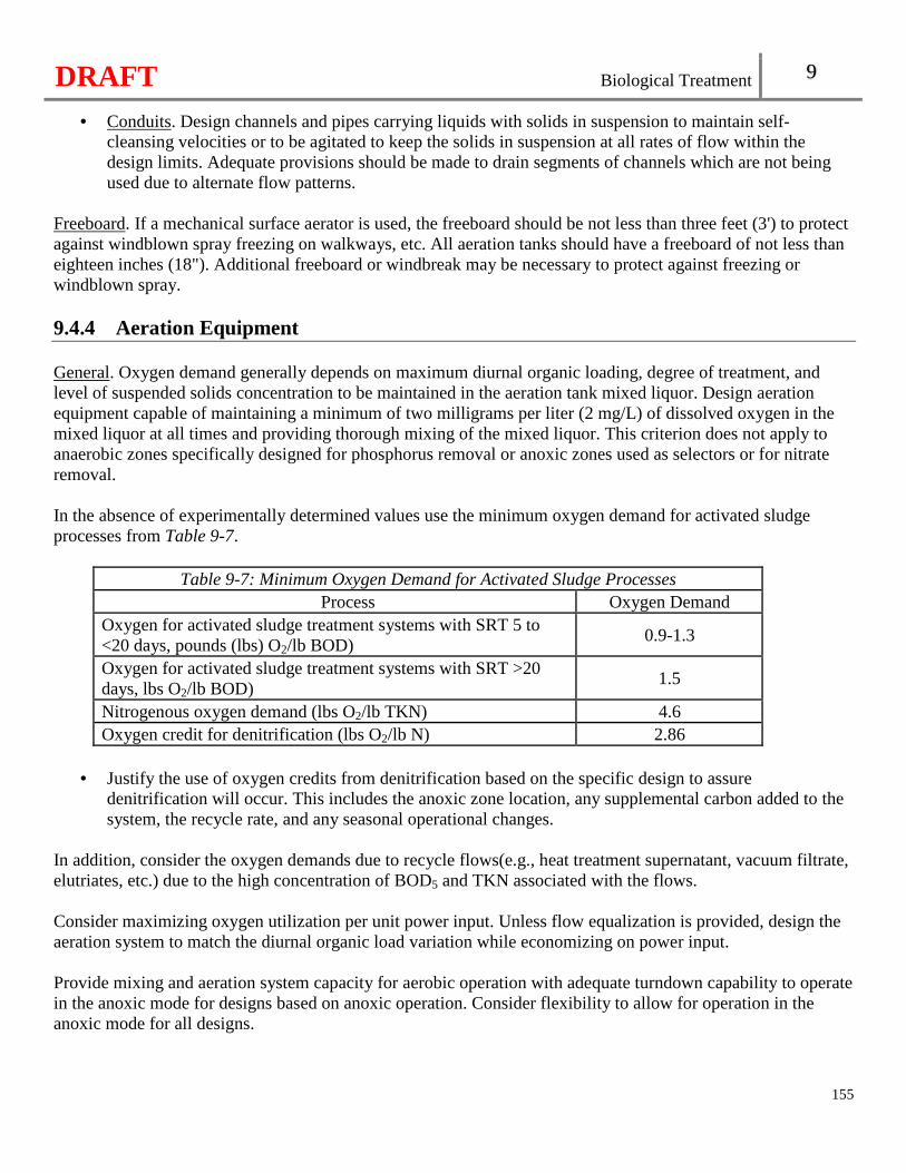
DRAFT Biological Treatment 9
155
• Conduits. Design channels and pipes carrying liquids with solids in suspension to maintain self-cleansing velocities or to be agitated to keep the solids in suspension at all rates of flow within the design limits. Adequate provisions should be made to drain segments of channels which are not being used due to alternate flow patterns.
Freeboard. If a mechanical surface aerator is used, the freeboard should be not less than three feet (3') to protect against windblown spray freezing on walkways, etc. All aeration tanks should have a freeboard of not less than eighteen inches (18"). Additional freeboard or windbreak may be necessary to protect against freezing or windblown spray. 9.4.4 Aeration Equipment General. Oxygen demand generally depends on maximum diurnal organic loading, degree of treatment, and level of suspended solids concentration to be maintained in the aeration tank mixed liquor. Design aeration equipment capable of maintaining a minimum of two milligrams per liter (2 mg/L) of dissolved oxygen in the mixed liquor at all times and providing thorough mixing of the mixed liquor. This criterion does not apply to anaerobic zones specifically designed for phosphorus removal or anoxic zones used as selectors or for nitrate removal. In the absence of experimentally determined values use the minimum oxygen demand for activated sludge processes from Table 9-7.
Table 9-7: Minimum Oxygen Demand for Activated Sludge Processes Process Oxygen Demand
Oxygen for activated sludge treatment systems with SRT 5 to <20 days, pounds (lbs) O2/lb BOD)
0.9-1.3
Oxygen for activated sludge treatment systems with SRT >20 days, lbs O2/lb BOD)
1.5
Nitrogenous oxygen demand (lbs O2/lb TKN) 4.6 Oxygen credit for denitrification (lbs O2/lb N) 2.86
• Justify the use of oxygen credits from denitrification based on the specific design to assure
denitrification will occur. This includes the anoxic zone location, any supplemental carbon added to the system, the recycle rate, and any seasonal operational changes.
In addition, consider the oxygen demands due to recycle flows(e.g., heat treatment supernatant, vacuum filtrate, elutriates, etc.) due to the high concentration of BOD5 and TKN associated with the flows. Consider maximizing oxygen utilization per unit power input. Unless flow equalization is provided, design the aeration system to match the diurnal organic load variation while economizing on power input. Provide mixing and aeration system capacity for aerobic operation with adequate turndown capability to operate in the anoxic mode for designs based on anoxic operation. Consider flexibility to allow for operation in the anoxic mode for all designs.
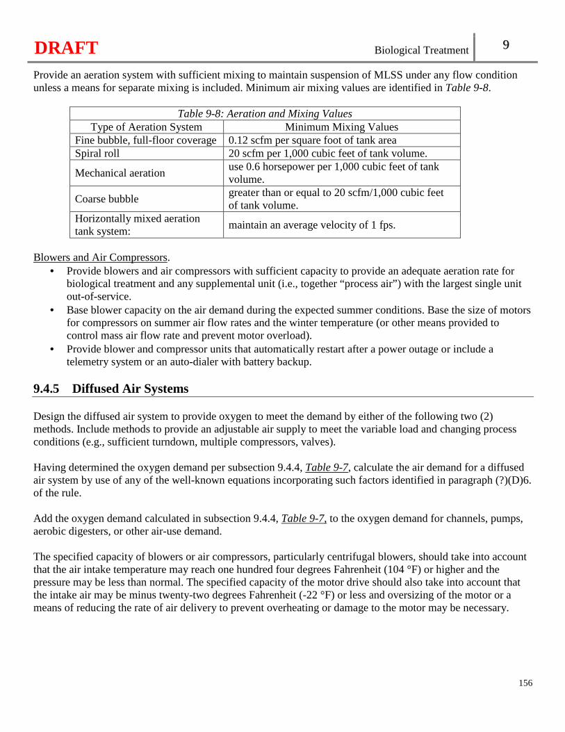
DRAFT Biological Treatment 9
156
Provide an aeration system with sufficient mixing to maintain suspension of MLSS under any flow condition unless a means for separate mixing is included. Minimum air mixing values are identified in Table 9-8.
Table 9-8: Aeration and Mixing Values Type of Aeration System Minimum Mixing Values
Fine bubble, full-floor coverage 0.12 scfm per square foot of tank area Spiral roll 20 scfm per 1,000 cubic feet of tank volume.
Mechanical aeration use 0.6 horsepower per 1,000 cubic feet of tank volume.
Coarse bubble greater than or equal to 20 scfm/1,000 cubic feet of tank volume.
Horizontally mixed aeration tank system:
maintain an average velocity of 1 fps.
Blowers and Air Compressors.
• Provide blowers and air compressors with sufficient capacity to provide an adequate aeration rate for biological treatment and any supplemental unit (i.e., together “process air”) with the largest single unit out-of-service.
• Base blower capacity on the air demand during the expected summer conditions. Base the size of motors for compressors on summer air flow rates and the winter temperature (or other means provided to control mass air flow rate and prevent motor overload).
• Provide blower and compressor units that automatically restart after a power outage or include a telemetry system or an auto-dialer with battery backup.
9.4.5 Diffused Air Systems Design the diffused air system to provide oxygen to meet the demand by either of the following two (2) methods. Include methods to provide an adjustable air supply to meet the variable load and changing process conditions (e.g., sufficient turndown, multiple compressors, valves). Having determined the oxygen demand per subsection 9.4.4, Table 9-7, calculate the air demand for a diffused air system by use of any of the well-known equations incorporating such factors identified in paragraph (?)(D)6. of the rule. Add the oxygen demand calculated in subsection 9.4.4, Table 9-7, to the oxygen demand for channels, pumps, aerobic digesters, or other air-use demand. The specified capacity of blowers or air compressors, particularly centrifugal blowers, should take into account that the air intake temperature may reach one hundred four degrees Fahrenheit (104 °F) or higher and the pressure may be less than normal. The specified capacity of the motor drive should also take into account that the intake air may be minus twenty-two degrees Fahrenheit (-22 °F) or less and oversizing of the motor or a means of reducing the rate of air delivery to prevent overheating or damage to the motor may be necessary.
DRAFT Biological Treatment 9
157
Provide multiple blower units so arranged and in such capacities as to meet the maximum oxygen demand with the single largest unit out-of-service. Provide for varying the volume of air delivered in proportion to the load demand of the facility. Provide aeration equipment that is easily adjustable in increments and can maintain solids suspension within these limits. Design diffuser systems capable of providing for the peak oxygen demand.
• Design the air diffusion piping and diffuser system to be capable of delivering normal air demands with minimal friction losses.
• Air piping systems should be designed such that total head loss from blower outlet (or silencer outlet where used) to the diffuser inlet does not exceed half a pound per square inch (0.5 psi) at average design conditions.
• The spacing of diffusers should be in accordance with the oxygen demand within the channel or tank and should be designed to facilitate adjustment of their spacing without major revision to air header piping.
• Design all facilities employing two (2) or less independent aeration tanks to incorporate removable diffusers that can be serviced and/or replaced without de-watering the tank.
Equip individual assembly units of diffusers with control valves, preferably with indicator markings for throttling or for complete shutoff. Design diffusers in any single assembly to have substantially uniform pressure loss. Provide air filters in numbers, arrangements and capacities to furnish an air supply sufficiently free from dust to prevent damage to blowers and clogging of the diffuser system used. Set the submerged depth for a diffuser at a depth of at least three feet (3') to facilitate maximum oxygen transfer. 9.4.6 High Purity Oxygen In addition to the above, the following applies to activated sludge systems which utilize high purity oxygen for aeration. Provide covered and compartmentalized reactors to provide a series of stages for biological growth each with a sampling point. An enclosed air-oxygen exhaust system shall be provided to collect and vent the reactor off-gases [See 10 CSR 20-8.180(5)(C)]. Normally, the power input should be half to one and three tenths horsepower per ten cubic feet of aerator volume (0.5-1.3 HP/10 ft3). Provide design basis for determining mixing demand and include provisions for rapid removal or cleaning of the mixers. Remotely locate the high purity oxygen storage and generation facilities and piping from areas where flammable or explosive substances may be present. Post warning signs in the area of the oxygen storage and generation facilities. The covered aeration basins should be equipped with explosive atmosphere monitors and alarms in accordance with applicable state and federal regulations. When explosive mixtures could occur, include an influent hydrocarbon monitor at the headworks to initiate operation of purge air blowers to vent reactor oxygen.
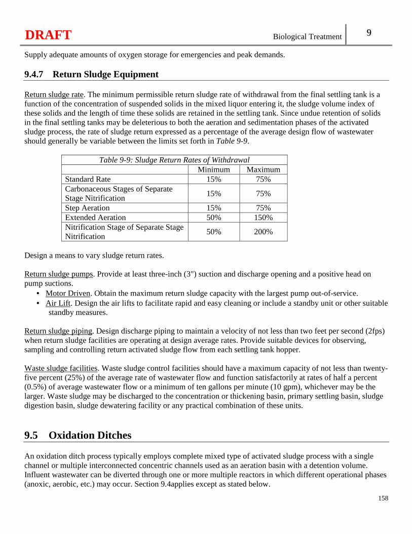
DRAFT Biological Treatment 9
158
Supply adequate amounts of oxygen storage for emergencies and peak demands. 9.4.7 Return Sludge Equipment Return sludge rate. The minimum permissible return sludge rate of withdrawal from the final settling tank is a function of the concentration of suspended solids in the mixed liquor entering it, the sludge volume index of these solids and the length of time these solids are retained in the settling tank. Since undue retention of solids in the final settling tanks may be deleterious to both the aeration and sedimentation phases of the activated sludge process, the rate of sludge return expressed as a percentage of the average design flow of wastewater should generally be variable between the limits set forth in Table 9-9.
Table 9-9: Sludge Return Rates of Withdrawal Minimum Maximum
Standard Rate 15% 75% Carbonaceous Stages of Separate Stage Nitrification
15% 75%
Step Aeration 15% 75% Extended Aeration 50% 150% Nitrification Stage of Separate Stage Nitrification
50% 200%
Design a means to vary sludge return rates. Return sludge pumps. Provide at least three-inch (3") suction and discharge opening and a positive head on pump suctions.
• Motor Driven. Obtain the maximum return sludge capacity with the largest pump out-of-service. • Air Lift. Design the air lifts to facilitate rapid and easy cleaning or include a standby unit or other suitable
standby measures. Return sludge piping. Design discharge piping to maintain a velocity of not less than two feet per second (2fps) when return sludge facilities are operating at design average rates. Provide suitable devices for observing, sampling and controlling return activated sludge flow from each settling tank hopper. Waste sludge facilities. Waste sludge control facilities should have a maximum capacity of not less than twenty-five percent (25%) of the average rate of wastewater flow and function satisfactorily at rates of half a percent (0.5%) of average wastewater flow or a minimum of ten gallons per minute (10 gpm), whichever may be the larger. Waste sludge may be discharged to the concentration or thickening basin, primary settling basin, sludge digestion basin, sludge dewatering facility or any practical combination of these units.
9.5 Oxidation Ditches An oxidation ditch process typically employs complete mixed type of activated sludge process with a single channel or multiple interconnected concentric channels used as an aeration basin with a detention volume. Influent wastewater can be diverted through one or more multiple reactors in which different operational phases (anoxic, aerobic, etc.) may occur. Section 9.4applies except as stated below.
DRAFT Biological Treatment 9
159
9.5.1 General For design average flows greater than one million gallon per day (1 MGD), provide split flow reactors. Consider multiple reactors for design average flows less than one million gallons per day (1 MGD). 9.5.2 Design A multiple concentric channel basin may have any number of interconnected channels. This channel design scheme provides some process flexibility, since with minor modifications it can be changed to other activated sludge process modes. Provide a volume to facilitate eighteen to twenty-four (18-24) hours hydraulic detention time at average dry weather flow. Influent wastewater and returned sludge should enter the reactor immediately upstream of the rotor that is farthest from the effluent control weir. Loadings are outlined in subsection 9.4.3 Table 9-6, Activated Sludge Process Loadings. Provide a minimum of four feet (4') depth. Install automatically controlled weirs to regulate flow direction and alternating operation of aeration/mixing equipment. Include provisions for taking a single train system out-of-service for maintenance or during an upset (i.e., equalization basin). Multiple ditch designs have a minimum of two (2) complete rotor units and are designed so a single rotor is capable of treating the design average oxygen demand. Place rotors before a long, straight ditch section. Provide a method to control rotor submergence. Provide a minimum of two (2) mixers/aerators per ditch to maintain horizontal mixing with one unit out-of-service. Provide elevated walkways for rotor maintenance. Do not support rotor weight directly by gear reduction or motor equipment. Protect motors, gear reduction equipment and bearings from inundation and rotor spray.
DRAFT Biological Treatment 9
160
9.6 Sequencing Batch Reactor (SBR) Sequencing batch reactor (SBR) is a fill-and-draw activated sludge treatment system. Although the processes involved in SBR are identical to the conventional activated sludge process, SBR is a compact and time oriented system and all the processes are carried out sequentially in the same tank. 9.6.1 General The minimum total basin volume shall be equal to the design daily influent flow volume and either upstream in-line or off-line storage is necessary to minimize influent flow during settling and decanting [See 10 CSR 20-8.180(6)]. If design average flow is less than one million gallons per day (1 MGD), install a minimum of two (2) reactor basins. If design average flow is equal to or greater than one million gallons per day (1 MGD), install a minimum of four (4) reactor basins. 9.6.2 Design Design each reactor to operate in a cyclic mode with sufficient time to fill, aerate, settle and remove the clarified liquid. Provide at least eighteen (18) hours of hydraulic detention time in the reactor. Size the reactor volume on the hydraulic retention time and decant volume. The reactor MLSS and MLVSS concentrations and aeration tank volumetric loading should be calculated at the low-water level. Design the SBR tank with a minimum sidewater depth of fifteen feet (15'). Include influent baffling and physical separation from the decanter in the design of an SBR with two (2) tanks or a SBR system operating with a continuous feed during settling and decanting phases. Provide a dedicated means of transferring solids between aeration basins. Include an overflow to another aeration tank(s) or a storage tank in each SBR tank. Provide influent baffling using a baffle wall and adequate physical separation of the influent from the decanter for any basin which may operate with a continuous feed during the settle and decant phases. The baffling directs the influent wastewater below the sludge blanket. Average horizontal velocities through each baffle wall opening should not exceed one foot per second (1 fps) at design peak hourly flows Evaluate system reliability with any single aeration tank unit out-of-service and the instantaneous delivery of flow in the design of decanter weirs and approach velocities. Locate inlets to each basin as far as possible from the outlet and in no case closer than ten feet (10'). Provide a high liquid level overflow between basins. Locate as far as possible from the outlet device.
DRAFT Biological Treatment 9
161
9.6.3 Aeration Since SBRs are considered a variation of the activated sludge process, section 9.4 applies. As all processes are completed in a single reactor, consider the following:
• Avoid aeration and/or mixing equipment that may produce flow patterns within the aeration tank which interfere with quiescent settling. Establish the discharge pressure of the blowers at the maximum water depth. Fixed decanters should not be used in basins where simultaneous fill and decant may occur, or where the sludge may be difficult to settle.
• Where designed for biological phosphorus removal or denitrification, provide mechanical mixing sized to thoroughly mix the entire tank from a settled condition within five (5) minutes without aeration.
9.6.4 Decanter System Floating decanters or similar mechanical devices which allow the treated effluent to be drawn near the water surface throughout the decant phase are recommended for added process control. The decantable volume and decanter capacity of the sequencing batch reactor system with the largest basin out-of-service should be sized to pass at least seventy-five percent (75%) of the design maximum day flow without changing cycle times. A decantable volume of at least four (4) hours with the largest basin out of service based on one hundred percent (100%) of the design maximum day flow is permissible. Design the decanter to control the velocity at an inlet port or at the edge of submerged weirs to prevent vortexing, disturbance of the settled sludge, and entry of floating materials. Design the entrance velocity to a decanter not to exceed one foot per second (1 fps) at the maximum design flow condition. Design the decanter system to draw effluent from twelve to eighteen inches (12-18") below the surface and to prevent floating scum from entering the system during fill and aeration periods. Maintain a zone of separation between the settled sludge and the decanter of no less than twelve inches (12"). Prevent solids from entering during a react cycle by:
• Physically raising the decanter above the water surface; • Recycling treated effluent to wash out solids trapped in a decanter; or • Mechanically closing a decanter when it is not in use.
A fixed decanter may be used except in a basin where simultaneous fill and decant may occur. Include additional decantable storage volume with a fixed level decanter because of the added settling time before a discharge may occur. Two (2) trains or floating decanter are acceptable alternatives. 9.6.5 Scum Management Provide scum baffles or other suitable arrangement and scum removal facilities, such as telescoping valves or high-water overflows. Consider prevailing winds.
DRAFT Biological Treatment 9
162
9.6.6 Sludge Management Provide a system separate from the decant piping allowing sludge to be wasted during the DECANT and/or IDLE phases of each process cycle. The location point(s) in the SBR tank for sludge wasting should be removed from the decanter(s) if wasting may occur during the DECANT phase. If decant pumps are used for sludge transfer, flush all solids in the decant piping and recycle back to the SBR.
All sludge transfer and wasting pumps should be accessible for maintenance without dewatering the tank. Waste sludge control facilities have a rate per day equal to fifty percent (50%) of the total basin volume. 9.6.7 Operations and Maintenance Consider the means and frequency for removal of grit and other debris from the SBR basins. Adequate space for equipment access (possibly cranes) should be considered, especially if the tanks are deep. Include a high-level alarm that notifies facility staff at facilities that are not staffed twenty-four (24) hours each day. Provide a programmable logic controller (PLC). Multiple PLCs should be provided as necessary to ensure rapid process recovery and minimize the deterioration of effluent quality from the failure of a single controller. Provide an uninterruptible power supply with electrical surge protection for each PLC to retain program memory (i.e., process control program, last-known set points and measured process/equipment status, etc.) through a power loss. Provide a hard-wired backup for manual override in addition to automatic process control. Allow independent operation of each tank for both automatic and manual controls.
9.7 Membrane Bioreactor (MBR) 9.7.1 General For wastewater treatment plants with a flow equal to or greater than one hundred thousand gallons per day (100,000 gpd), the MBR process must be designed with a minimum of two (2) membrane trains capable of treating the daily average flow with one membrane cassette out-of-service [See 10 CSR 20-8.180(7)(A)1.]. For wastewater treatment facilities with a design average flow less than one hundred thousand gallons (100,000 gpd), the MBR process should be designed to have two (2) membrane cassettes but may be designed to have a single membrane cassette provided—
• The design includes provisions to manage flows during cleaning in place and recovery cleaning (e.g., temporary storage, provisions to remove/replace individual module for separate cleaning without impacting remainder of membranes in the tank);
• Design flux criteria must be satisfied with one (1) membrane module out-of-service (e.g., for external clean in place, recovery cleaning, repair). For purposes of these criteria, a membrane
DRAFT Biological Treatment 9
163
module is the smallest membrane unit capable of separate removal from the tank while maintaining operation of other membrane units in the same tank; and [See 10 CSR 20-8.180(7)(A)2.]
• Membranes placed in the aeration basin(s) rather than a separate membrane tank shall have [See 10 CSR 20-8.180(7)(A)3.]:� Individual modules and individual diffusers can be removed separately for maintenance and
repair; and � Aeration basin(s) volume sized for complete nitrification.
Membranes.
• Use performance based membrane material with a manufacturer warranty. • The nominal pore size used in an MBR process should be equal to or less than four tenths microns
(0.4µm). • Use of a membrane system other than a hollow fiber system, tubular system, or a flat plate system
will be considered new treatment technology and subject to section 1.4. 9.7.2 Preliminary Treatment Each MBR system shall [See 10 CSR 20-8.180(7)(B)]--
• Be consistent with the membrane manufacturer recommendations; • Provide grit removal; • Provide oil and grease removal when the levels in the influent may cause damage to the
membranes; • Provide a fine screen and high water alarm, designed to treat peak hourly flow. Coarse screens
followed by fine screens may be used in larger facilities to minimize the complications of fine screening; and
• Provide a duplicate fine screen and a high water alarm. 9.7.3 Design Size the MBR system (including membranes and flow equalization) to hydraulically pass anticipated peak instantaneous flows. Provide justification for the design operational range of MLSS concentration set by the manufacturer. The expected MLSS ranges in both the bioreactor and in the membrane tank are a minimum of four thousand milligrams per liter to a maximum of fifteen thousand milligrams per liter (4,000-15,000 mg/L). Base flux rates on demonstrated long-term performance data and adequate safety factors. The expected net flux rates are listed below—
• An average daily net flux rate of not more than fifteen gallons per day per square-foot (15 gpd/ft2) of membrane area;
• A peak daily net flux rate equal to or less than one and a quarter (1.25) times the average daily net flux rate; and
• A two (2)-hour peak net flux rate equal to or less than one and half (1.5) times the average daily net flux rate.
DRAFT Biological Treatment 9
164
Accommodate higher flows with flow equalization, off-line storage, or reserve membrane basin capacity for facilities that expect a peak instantaneous flow rate greater than two and a half (2.5) times the design maximum daily flow. The design solids retention time (SRT) is at least ten (10) days but no more than twenty-five (25) days. Include long-term process data from operational facilities to demonstrate no detrimental impacts on membrane operation and permeability when SRT is not within the recommended range. 9.7.4 Aeration The aeration blowers must provide adequate air for membrane scour and process demands [See 10 CSR 20-8.180(7)(C)]. Include oxygen monitoring and an alarm. 9.7.5 Redundancy The facility shall have one (1) of the following at a minimum [See 10 CSR 20-8.180(7)(D)]:
• The ability to run in full programmable logic contr ol (PLC) or standby power mode in case of an automatic control failure;
• An operational battery backup PLC if manual control is not possible; or • Sufficient standby power generating capabilities to provide continuous flow through the
membranes during a power outage (e.g., preliminary screening, process aeration, recycle/RAS/permeate pumps, air scour, vacuum pumps) or an adequate method to handle flow for an indefinite period (e.g., private control of influent combined with contingency methods). See subsection 5.5.1 for emergency Power for aeration.
9.7.6 Disinfection MBRs utilizing membranes with a pore size no larger than four tenths microns (0.40 µm) do not require an additional means of disinfection. 9.7.7 Sludge Recycling and Wasting Design sludge recycle rates for MBR systems should be between two hundred and six hundred percent (200-600%) of influent flow. Include justification for the selected recycle rate, taking into account peak hourly flows and aeration basin dissolved oxygen demand in the summary of design. Various waste streams within the treatment process may have different recycle rates. Include provisions to adjust the sludge recycle pumps (e.g. the pumps can be variable flow driven, operated by pressure gauge, or valved to account for the range of operating conditions.) Consider prevention of excess dissolved oxygen from entering anoxic and anaerobic zones or account for oxygen recycle.
DRAFT Biological Treatment 9
165
Identify location(s) and metering of waste sludge flow (e.g., membrane basin, aeration basin, recirculation lines, or basin surfaces). 9.7.8 Operations and Maintenance The MBR design shall [See 10 CSR 20-8.180(7)(E)]—
• Include provisions to monitor membrane integrity; • Provide on-line continuous turbidity monitoring of filtrate or an equivalent for operational control
and indirect membrane integrity monitoring for a tr eatment plant with design average flow greater than or equal to one hundred thousand gallons (100,000 gpd); and
• Include provisions to remove membrane cassette for cleaning considering the membrane cassette wet weight plus additional weight of the solids accumulated on the membranes. Identify an appropriate combination of cleaning strategies to maintain membrane permeability.
9.8 Moving Bed Bioreactor (MBBR) The moving bed biological reactor (MBBR) process is an attached growth activated sludge process that uses suspended plastic carrier media within the bioreactor to provide surface area for biofilm growth. MBBRs are distinctive in that they use low density media kept in motion using aeration or mechanical mixers. 9.8.1 Preliminary Treatment Preliminary treatment, including screening and grit removal, is a necessary component of MBBR processes to prevent plastic biofilm carrier retention screen blinding and the accumulation of inert material (e.g., rags, plastics, and sand) in the MBBR tank(s). A MBBR treatment system shall have upstream preliminary treatment units that are capable of [See 10 CSR 20-8.180(8)]:
• Screening to reduce pass-through and suspended solids; • Grit removal; • Oil and grease removal; • Primary clarification; • Control the release of hydrogen sulfide; and • Should include corrosion protection.
Fine screens with no larger than an eighth of an inch (0.125”) typically are used in MBBR facilities. If using a larger screen opening, include the manufacturer’s specifications and design justification in the summary of design. Bar screening or comminution are not suitable as the sole means of preliminary treatment.
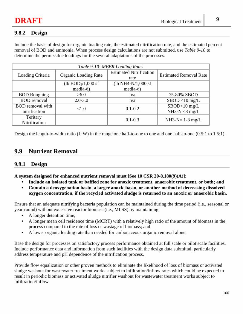
DRAFT Biological Treatment 9
166
9.8.2 Design Include the basis of design for organic loading rate, the estimated nitrification rate, and the estimated percent removal of BOD and ammonia. When process design calculations are not submitted, use Table 9-10 to determine the permissible loadings for the several adaptations of the processes.
Table 9-10: MBBR Loading Rates
Loading Criteria Organic Loading Rate Estimated Nitrification
rate Estimated Removal Rate
(lb BOD5/1,000 sf
media-d) (lb NH4-N/1,000 sf
media-d)
BOD Roughing >6.0 n/a 75-80% SBOD BOD removal 2.0-3.0 n/a SBOD <10 mg/L
BOD removal with nitrification
<1.0 0.1-0.2 SBOD<10 mg/L NH3-N <3 mg/L
Teritary Nitrification
0.1-0.3 NH3-N= 1-3 mg/L
Design the length-to-width ratio (L:W) in the range one half-to-one to one and one half-to-one (0.5:1 to 1.5:1).
9.9 Nutrient Removal 9.9.1 Design A system designed for enhanced nutrient removal must [See 10 CSR 20-8.180(9)(A)]:
• Include an isolated tank or baffled zone for anoxic treatment, anaerobic treatment, or both; and • Contain a deoxygenation basin, a larger anoxic basin, or another method of decreasing dissolved
oxygen concentration, if the recycled activated sludge is returned to an anoxic or anaerobic basin. Ensure that an adequate nitrifying bacteria population can be maintained during the time period (i.e., seasonal or year-round) without excessive reactor biomass (i.e., MLSS) by maintaining:
• A longer detention time; • A longer mean cell residence time (MCRT) with a relatively high ratio of the amount of biomass in the
process compared to the rate of loss or wastage of biomass; and • A lower organic loading rate than needed for carbonaceous organic removal alone.
Base the design for processes on satisfactory process performance obtained at full scale or pilot scale facilities. Include performance data and information from such facilities with the design data submittal, particularly address temperature and pH dependence of the nitrification process. Provide flow equalization or other proven methods to eliminate the likelihood of loss of biomass or activated sludge washout for wastewater treatment works subject to infiltration/inflow rates which could be expected to result in periodic biomass or activated sludge nitrifier washout for wastewater treatment works subject to infiltration/inflow.
DRAFT Biological Treatment 9
167
Provide feed equipment for the addition of chemicals to maintain a residual alkalinity in the aeration basin contents (i.e., mixed liquor) when necessary, based on the characteristics of the influent wastewater. When fully nitrifying, impacts to the effluent pH could be observed. 9.9.2 Aeration Provide mixing and aeration system capacity for aerobic operation with adequate turndown capability. Flexibility to allow for operation in the anoxic mode should be considered for all designs. The design oxygen concentration range used for sizing aeration systems for treatment zones shall be as follows [See 10 CSR 20-8.180(9)(B)]:
• Anoxic: not more than half a milligram per liter (0.5 mg/L); • Aerobic: at least one and half milligrams per liter but not more than three milligrams per liter
(1.5-3.0 mg/L); and • Membranes: at least two milligrams per liter but not more than eight milligrams per liter (2.0-8.0
mg/L). 9.10 Biological Phosphorus Removal Reserved.

DRAFT
168
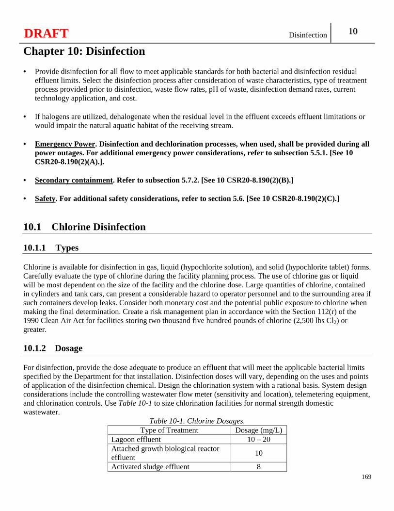
DRAFT Disinfection 10
Chapter 10: Disinfection
169
• Provide disinfection for all flow to meet applicable standards for both bacterial and disinfection residual
effluent limits. Select the disinfection process after consideration of waste characteristics, type of treatment process provided prior to disinfection, waste flow rates, pH of waste, disinfection demand rates, current technology application, and cost.
• If halogens are utilized, dehalogenate when the residual level in the effluent exceeds effluent limitations or
would impair the natural aquatic habitat of the receiving stream.
• Emergency Power. Disinfection and dechlorination processes, when used, shall be provided during all power outages. For additional emergency power considerations, refer to subsection 5.5.1. [See 10 CSR20-8.190(2)(A).].
• Secondary containment. Refer to subsection 5.7.2. [See 10 CSR20-8.190(2)(B).]
• Safety. For additional safety considerations, refer to section 5.6. [See 10 CSR20-8.190(2)(C).]
10.1 Chlorine Disinfection 10.1.1 Types Chlorine is available for disinfection in gas, liquid (hypochlorite solution), and solid (hypochlorite tablet) forms. Carefully evaluate the type of chlorine during the facility planning process. The use of chlorine gas or liquid will be most dependent on the size of the facility and the chlorine dose. Large quantities of chlorine, contained in cylinders and tank cars, can present a considerable hazard to operator personnel and to the surrounding area if such containers develop leaks. Consider both monetary cost and the potential public exposure to chlorine when making the final determination. Create a risk management plan in accordance with the Section 112(r) of the 1990 Clean Air Act for facilities storing two thousand five hundred pounds of chlorine (2,500 lbs Cl2) or greater. 10.1.2 Dosage For disinfection, provide the dose adequate to produce an effluent that will meet the applicable bacterial limits specified by the Department for that installation. Disinfection doses will vary, depending on the uses and points of application of the disinfection chemical. Design the chlorination system with a rational basis. System design considerations include the controlling wastewater flow meter (sensitivity and location), telemetering equipment, and chlorination controls. Use Table 10-1 to size chlorination facilities for normal strength domestic wastewater.
Table 10-1. Chlorine Dosages. Type of Treatment Dosage (mg/L)
Lagoon effluent 10 – 20 Attached growth biological reactor effluent
10
Activated sludge effluent 8
DRAFT Disinfection 10
170
Tertiary filtration effluent 6 Nitrified effluent 6
10.1.3 Container Gaseous chlorine cylinders. One hundred fifty pound (150 lb) cylinders are typically used where chlorine gas consumption is less than one hundred fifty pounds per day (150 lbs/day). Store cylinders in an upright position with adequate support brackets and chains at two thirds (2/3) of cylinder height for each cylinder. Gaseous chlorine ton containers. Consider the use of one (1)-ton containers where the average daily chlorine consumption is over one hundred fifty pounds (150 lb). For one (1)-ton containers provide the following:
• A hoist with a two (2)-ton capacity; and • A monorail or hoist with sufficient lifting height to pass one (1) container over another.
Gaseous chlorine tank cars. • At large installations, consider the use of tank cars, generally accompanied by evaporators. Evaluate
area wide public safety. No interruption of chlorination is permitted during tank car switching. • Locate the tank car being used for the chlorine supply on a dead end, level track that is a private siding.
Protect the tank car from accidental bumping by other railway cars by a locked derail device, a closed locked switch, or both. Clearly post “DANGER - CHLORINE” in the area around tank car(s). Secure the tank car from unauthorized access.
• Provide the tank car site with a suitable operating platform at the unloading point for easy access to the protective housing or the tank car for the connection of flexible feedlines and valve operation. Provide adequate area lighting for night time operation and maintenance.
Liquid hypochlorite solutions.
• Select sturdy, non-metallic lined storage containers for hypochlorite solutions, and equip with secure tank tops and pressure relief and overflow piping.
• Install overflow piping with a water seal or other device to prevent tanks from venting to the indoors. • Locate or vent storage tanks outside. • Provide adequate protection from light and extreme temperatures. • Locate tanks where leakage will not cause corrosion or damage to other equipment. • Due to deterioration of hypochlorite solutions over time, it is recommended that containers not be sized
to hold more than thirty (30) day supply. At larger facilities and locations where delivery is not a problem, it may be desirable to limit on-site storage to one (1) week.
• For additional chemical housing considerations, refer to subsection 5.7.3. Dry hypochlorite compounds.
• Store dry hypochlorite compounds (tablets) in tightly closed containers and stored in a cool, dry location.
• Consider means of dust, depending on the size of the facility and the quantity of compound used. • For additional chemical housing considerations, refer to subsection 5.7.3.
10.1.4 Equipment Scales. Provide scales for weighing cylinders and containers at all facilities using chlorine gas. At large
DRAFT Disinfection 10
171
wastewater treatment facilities, scales of the indicating and recording type are recommended. Provide scales of corrosion-resistant materials. Evaporators. Where manifolding of several cylinders or ton containers will be necessary to evaporate sufficient chlorine. Give consideration to the installation of evaporators, to produce the necessary quantity of gas. Automatic switchovers. Provide automatic gas container or liquid chlorine tank changeover. Flow pacing. Pace the chlorine dose according to flow and chlorine residual for all wastewater treatment facilities with a design average flow of one hundred thousand gallons per day (100,000 gpd) or greater. Control dose pacing by the effluent flow meters and locate the residual analyzer probe to ensure appropriate lag time for residual analyzer control. Mixing. Positively mix the disinfectant as rapidly as possible, with a complete mix being achieved in three (3) seconds. This may be accomplished by either the use of turbulent flow regime or a mechanical flash mixer. Contact period. A minimum contact period of fifteen (15) minutes at design peak hourly flow or maximum rate of pumpage shall be provided after thorough mixing [See 10 CSR 20-8.190(3)(A)]. When evaluating existing chlorine contact tanks, perform field tracer studies to assure adequate contact time. Contact tank.
• Construct chlorine contact tank to reduce short-circuiting of flow to a practical minimum. Provide “over-and-under” or “end-around” baffling to minimize short-circuiting in tanks not provided with continuous mixing. Install baffles parallel to the longitudinal axis of the chamber with a minimum length to width ratio of forty to one (40:1) (the total length of the channel created by the baffles should be forty (40) times the distance between the baffles).
• Design the tank to facilitate maintenance and cleaning without reducing effectiveness of disinfection. Provide duplicate tanks, mechanical scrapers, or portable deck-level vacuum cleaning equipment. Consider providing skimming devices on all contact tanks.
• Covered tanks are discouraged. • Provide measures to dewater each contact tank. For additional unit dewatering considerations, refer to
subsection 5.3.3.
Piping and connections. • Select piping materials manufactured specifically chlorine gas. Design piping systems to be as simple as
possible with a minimum number of joints. Piping should be well supported and protected against temperature extremes.
• Provide protection for all lines designated to handle dry chlorine to exclude moisture. Even minute traces of water added to chlorine results in a corrosive attack.
• Low pressure lines made of hard rubber, saran-lined, rubber-lined, polyethylene, polyvinyl chloride, or other approved materials are satisfactory for wet chlorine or aqueous solutions of chlorine.
• Where sulfur dioxide is used, design the piping and fittings for chlorine and sulfur dioxide systems so that interconnection between the two (2) systems cannot occur.
• Color code the chlorine system piping and label to distinguish it from other plant piping. For additional painting information, refer to subsection 5.3.5.
Standby equipment and spare parts. Standby equipment of sufficient capacity should be available to replace the
DRAFT Disinfection 10
172
largest unit during shutdowns. Provide spare parts to be available for all disinfection equipment to replace all parts subject to wear and breakage. Chlorinator water supply. Maintain an ample supply of water available for operating the chlorinator. Provide duplicate equipment where a booster pump is utilized. Provide protection of potable water supply (subsection 5.5.4). Adequately filtered facility effluent should be considered for use in the chlorinator. Leak detection and controls.
• Ammonium hydroxide solution can be used for detecting chlorine leaks. • Provide a leak repair kit approved by the Chlorine Institute where one (1)-ton containers or tank cars are
used. • Caustic soda solution reaction tanks for absorbing the contents of leaking one (1)-ton containers where
such containers are in use. • Consider the installation of automatic gas detection and related alarm equipment.
10.1.5 Gaseous Chlorine Housing Situate chlorination equipment as close to the application point as reasonably possible. Feed and storage rooms shall [See 10 CSR 20-8.190(3)(B)1.]–
• Have chlorine gas feed and storage rooms constructed of fire and corrosion resistant material; • Provide a gas-tight room to separate equipment from any other portion of the building if gas
chlorination equipment or chlorine cylinders are to be in a building used for other purposes; • Have smooth floor surfaces that are chemical resistant, impervious, and slip resistant. Floor
drains are discouraged. Design floor drains, where provided, with the ability to be plugged and sealed;
• Have doors to this room that only open to the outside of the building, and are equipped with panic hardware. Provide door locks to prevent unauthorized access, but do not need a key to exit the locked room using the panic hardware;
• Be well-lit with lights that are sealed so that they will continue working during a chlorine leak. Comply with subsection 5.5.2 requirements for Class I, Division 2 locations when selecting lights and electrical equipment;
• Be at ground level and permit easy access to all equipment; • Separate storage areas for one (1)-ton cylinders from the feed area and; • Have designated areas for “full” and “empty” cylinder storage.
Inspection window. Install a clear glass, gas-tight, and shatter resistant inspection window in an exterior door or interior wall of the chlorination room to permit the units to be viewed without entering the room. The feeder settings and scale readings should be easily read from the inspection window or remotely read in a separate control room. Heating and cooling.
• Rooms containing disinfection equipment shall be provided with a means of heating and cooling so that a temperature of at least sixty degrees Fahrenheit (60° F) and no more than eighty six degrees Fahrenheit (86°F) can be maintained [See 10 CSR 20-8.190(3)(B)2.A.].
• Maintain cylinders and gas lines at the same temperature as the feed equipment.
DRAFT Disinfection 10
173
• Locate equipment used to heat a chlorine storage or feed area a safe distance from chlorine cylinders as to avoid blowing conditioned air onto cylinders
• Heating or air conditioning equipment provided for the chlorinator room shall be separate from central heating and air conditioning systems to prevent chlorine gas from entering the central system and central heating or cooling ducts are not allowed to terminate or pass through a chlorinator room[See 10 CSR 20-8.190(3)(B)2.B.].
Ventilation shall conform to the following [See 10 CSR 20-8.190(3)(B)3.]:
• Install forced, mechanical ventilation to provide one (1) complete fresh air change per minute when the chlorinator room is occupied. Construct fans of chemical resistant materials and have chemical proof motors. Squirrel cage type fans located outside the chlorinator room may be approved if the fan housings and ducting are airtight and made of chlorine and corrosion resistant material.
• Locate the entrance to the air exhaust duct from the room no more than twelve inches (12") off the floor. Locate the point of discharge as not to contaminate the air inlet to any buildings or present a hazard at the access to the chlorinator room or other inhabited areas. Utilize louvers for air exhaust to facilitate airtight closure.
• Locate air inlets as to provide cross ventilation. Place the outside air inlet at least three feet (3') above grade. Utilize louvers for air inlets to facilitate airtight closure.
• Position the vent hose from the chlorinator to the outside atmosphere above grade. Provide passive vent screens.
Electrical controls. Switches for fans and lights shall be outside of the chlorinator room at the entrance [See 10 CSR 20-8.190(3)(B)4.]. A labeled signal light indicating fan operation should be provided at each entrance, if the fan can be controlled from more than one (1) point. Ambient gas detectors. Provide an ambient chlorine gas detector in the chlorine storage room. Design the gas detector to be interlocked with the fan and alarm system. Refer to subsection 10.1.6 for further alarm system guidance. Protective and respiratory gear. Respiratory air-pac protection equipment, that meets the requirements of the Department of Health and Human Services Centers for Disease Control and Prevention National Institute for Occupational Safety and Health NIOSH Pocket Guide to Chemical Hazards, as published September 2007, shall be available where chlorine gas is handled, and stored at a convenient location, but not inside any room where chlorine is used or stored [See 10 CSR 20-8.190(3)(B)5.]. This standard is incorporated by reference in this document, as published by U.S. Government Printing Office, P.O. Box 371954, Pittsburgh, PA 15250-7954. This rule does not incorporate any subsequent amendments or additions. Post instructions for use near the stored equipment. 10.1.6 Alarm System The applicant shall conform to subsection 5.5.3and be responsible for specifying what the alarm requirements are necessary to assure consistent disinfection in compliance with the applicable bacteria limits and the disinfection residual limit in the effluent [See 10 CSR 20-8.190(3)(C)].
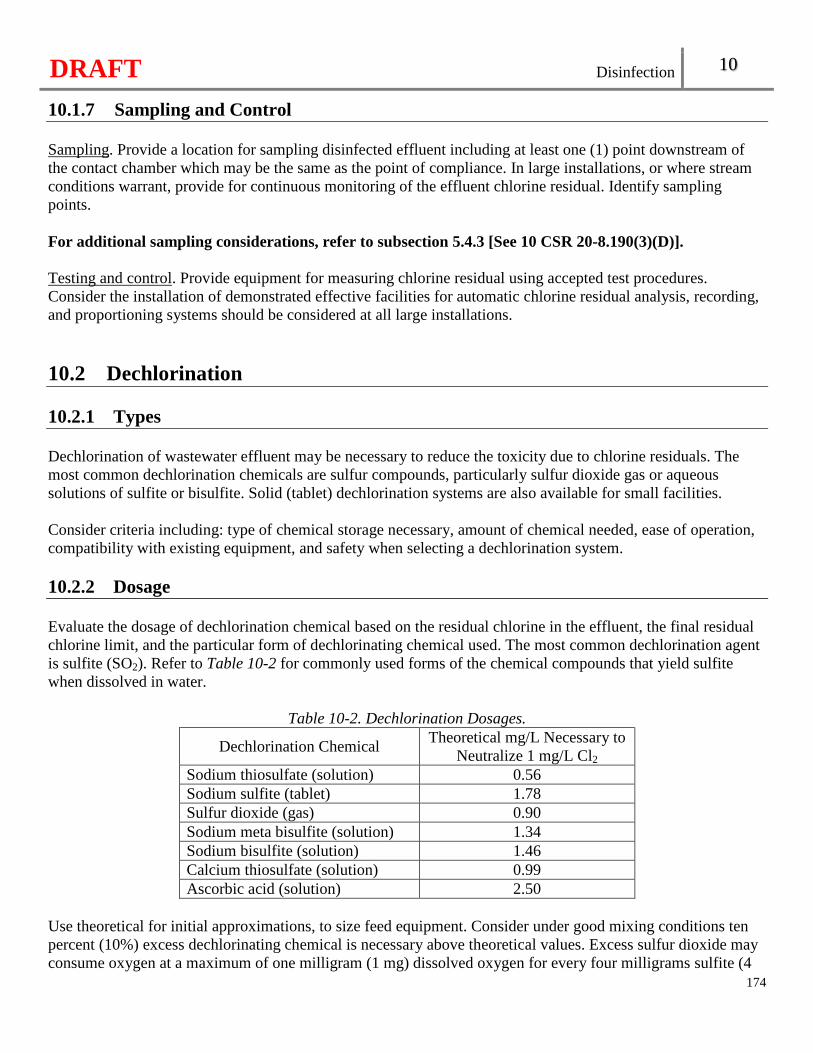
DRAFT Disinfection 10
174
10.1.7 Sampling and Control Sampling. Provide a location for sampling disinfected effluent including at least one (1) point downstream of the contact chamber which may be the same as the point of compliance. In large installations, or where stream conditions warrant, provide for continuous monitoring of the effluent chlorine residual. Identify samplingpoints. For additional sampling considerations, refer to subsection 5.4.3 [See 10 CSR 20-8.190(3)(D)]. Testing and control. Provide equipment for measuring chlorine residual using accepted test procedures. Consider the installation of demonstrated effective facilities for automatic chlorine residual analysis, recording, and proportioning systems should be considered at all large installations.
10.2 Dechlorination 10.2.1 Types Dechlorination of wastewater effluent may be necessary to reduce the toxicity due to chlorine residuals. The most common dechlorination chemicals are sulfur compounds, particularly sulfur dioxide gas or aqueous solutions of sulfite or bisulfite. Solid (tablet) dechlorination systems are also available for small facilities. Consider criteria including: type of chemical storage necessary, amount of chemical needed, ease of operation, compatibility with existing equipment, and safety when selecting a dechlorination system. 10.2.2 Dosage Evaluate the dosage of dechlorination chemical based on the residual chlorine in the effluent, the final residual chlorine limit, and the particular form of dechlorinating chemical used. The most common dechlorination agent is sulfite (SO2). Refer to Table 10-2 for commonly used forms of the chemical compounds that yield sulfite when dissolved in water.
Table 10-2. Dechlorination Dosages.
Dechlorination Chemical Theoretical mg/L Necessary to
Neutralize 1 mg/L Cl2 Sodium thiosulfate (solution) 0.56 Sodium sulfite (tablet) 1.78 Sulfur dioxide (gas) 0.90 Sodium meta bisulfite (solution) 1.34 Sodium bisulfite (solution) 1.46 Calcium thiosulfate (solution) 0.99 Ascorbic acid (solution) 2.50
Use theoretical for initial approximations, to size feed equipment. Consider under good mixing conditions ten percent (10%) excess dechlorinating chemical is necessary above theoretical values. Excess sulfur dioxide may consume oxygen at a maximum of one milligram (1 mg) dissolved oxygen for every four milligrams sulfite (4
DRAFT Disinfection 10
175
mg SO2). Liquid solutions come in various strengths. Dilute solutions further to provide the proper dose of dechlorination as needed. 10.2.3 Containers Select storage containers depending on dechlorination chemicals designated for use. Dilution tanks and mixing tanks are required when using dry compounds and may be necessary when using liquid compounds to deliver the proper dosage [See 10 CSR 20-8.190(4)(A)]. Solution containers should be covered to prevent evaporation and spills. 10.2.4 Feed Equipment, Mixing, and Contact Requirements Equipment.
• Use the same type of feeding equipment, with minor modifications, for sulfur dioxide gas as used for chlorine gas. Contact the manufacturer for specific equipment recommendations. Do not alternate use of equipment between the two (2) gasses. Vacuum solution feed of sulfur dioxide gas and a positive displacement pump for aqueous solutions of sulfite or bisulfite are common types of dechlorination feed equipment utilizing sulfur compounds.
• Include consideration of operator safety and overall public safety, in the selection of the type of feed equipment utilizing sulfur compounds, relative to the wastewater treatment facility’s proximity to populated areas and the security of gas cylinder storage. Take into account that the gas reliquifies quite easily during the selection and design of sulfur dioxide feeding equipment. Take special precautions when using one (1)-ton containers to prevent reliquefaction.
• Provide multiple units for adequate peak capacity and to provide a sufficiently low feed rate on turn down to avoid depletion of the dissolved oxygen concentrations in the receiving waters when necessary to meet operating ranges.
Mixing requirements. The dechlorination reaction with free or combined chlorine will generally occur within fifteen to twenty (15 – 20) seconds. Introduce dechlorination chemical at a point in the process where the hydraulic turbulence is adequate to assure thorough and complete mixing. If no such point exists, provide mechanical mixing. The high solubility of sulfite prevents it from escaping during turbulence. Solid dechlorination systems shall not be located in the chlorine contact tank [See 10 CSR 20-8.190(4)(B)1.]. Contact time. A minimum of thirty (30) seconds for mixing and contact time shall be provided at the design peak hourly flow or maximum rate of pumpage [See 10 CSR 20-8.190(4)(B)2.]. Provide a suitable sampling point downstream of the contact zone. Consider a means of reaeration to assure maintenance of an acceptable dissolved oxygen concentration in the stream following sulfonation. For additional post-aeration considerations, refer to section 12.1. Standby equipment and spare parts. The same requirements apply as for chlorination systems. See subsection 10.1.4, Standby equipment and spare parts.
DRAFT Disinfection 10
176
Sulfonator water supply. The same requirements apply as for chlorination systems. See subsection 10.1.4, Chlorinator water supply. 10.2.5 Housing Requirements Feed and storage rooms.
• The requirements for housing sulfite gas equipment shall follow the same guidelines as for chlorine gas. Refer to subsection 10.1.5 for specific details [See 10 CSR 20-8.190(4)(C)1.].
• Design mixing, storage, and solution delivery areas to contain or route solution spillage or leakage away from traffic areas to an appropriate containment unit.
Protective and respiratory gear. Respiratory air-pac protection equipment is the same as for chlorine. See subsection 10.1.5, Protective and respiratory gear. Leak repair kits of the type used for chlorine gas that are equipped with gasket material suitable for service with sulfur dioxide gas may be used. 10.2.6 Alarm System The same requirements apply as for chlorination systems. See subsection 10.1.6 [See 10 CSR 20-8.190(4)(D)]. 10.2.7 Sampling and Control
Sampling. Include facilities for sampling the dechlorinated effluent for residual chlorine, including at least one (1) point downstream of the dechlorination system which may be the same sampling point as that in subsection 10.1.7, Sampling.Make provisions to monitor for dissolved oxygen concentration after sulfonation when requested by the Department. Identify sampling points. For additional sampling considerations, refer to subsection 5.4.3. Testing and control. Make provision for manual or automatic control of sulfonator feed rates based on chlorine residual measurement or flow.
10.3 Ultraviolet Disinfection
10.3.1 General Critical parameters for UV disinfection units are dependent upon manufacturers’ design, lamp selection, tube materials, ballasts, configuration, control systems, and associated appurtenances.
10.3.2 Dosage and System Sizing General. The UV dosage shall be based on the design peak hourly flow, maximum rate of pumpage, or peak batch flow [See 10 CSR 20-8.190(5)(A)1.]. Batch discharges. Consider the following for wastewater treatment facilities with batch discharges, such as sequencing batch reactors:
DRAFT Disinfection 10
177
• The need for flow equalization prior to the UV system in order to maintain continuous operation; • If no flow equalization is provided for a batch discharger, the dosage shall be based on the peak
batch flow [See 10 CSR 20-8.190(5)(A)2.]; and • Design the UV system to have power cycled up to the maximum number of batches per day to
accommodate the batch discharges. Bioassay. Use an independent, third party bioassay to verify the design UV requirements. The UV system shall deliver the target dosage based on equipment derating factors and, if needed, have the UV equipment manufacturer verify that the scale up or scale down factor utilized in the design is appropriate for the specific application under consideration [See 10 CSR 20-8.190(5)(A)3.]. Keep the bioassay report available upon request by the Department. An independent, third party registered professional engineer needs to sign, seal, and date the bioassay report. New wastewater treatment facilities. The design delivered UV dosage for a new wastewater treatment facility shall be a minimum of thirty thousand microwatt seconds per centimeters squared (30,000 µW • s/cm2) based on MS-2 phage inactivation [See 10 CSR 20-8.190(5)(A)4.]. This dosage is to be delivered assuming a high quality effluent having at least sixty-five percent (65%) ultraviolet radiation transmittance (UVT) at two hundred fifty-four nanometers (254 nm) wave length.
• The use of a lower bioassay dose based on a different organism in similar water quality will be considered upon submittal of the bioassay to the Department in accordance with subsection 10.3.2, Bioassay.
Existing wastewater treatment facilities. Determine the UVT by testing the effluent’s UVT a minimum of once per week over a one (1) month period. It is the responsibility of the applicant to present the UVT test results and determined UV dosage to the Department. 10.3.3 Design Configuration and redundancy.
• Open channel systems. Provide at least two (2) banks for disinfection reliability and to ensure service during lamp cleaning or other necessary maintenance.
� Design facilities capable of treating the design average flow with one (1) bank out-of-service. � The combination of the total number of banks shall be capable of treating the design peak
hourly flow, maximum rate of pumpage, or peak batch flow [See 10 CSR 20-8.190(5)(B)1.]. � Provide at least one (1) bank for facilities with a design average flow of less than one hundred
thousand gallons per day (100,000 gpd) and have seasonal bacterial effluent limits. Provide at least one (1) stored spare module for maintenance.
• Closed vessel systems. Provide at least two (2) closed vessels for disinfection reliability and to ensure service during lamp cleaning or other necessary maintenance.
� Design facilities capable of treating the design average flow with one (1) closed vessel out-of-service.
� The combination of the total number of closed vessels shall be capable of treating the design peak hourly flow, maximum rate of pumpage, or peak batch flow [See 10 CSR 20-8.190(5)(B)2.].
Open channel system hydraulics.
• Design the approach channel unobstructed and without bends to prevent jetting and short circuiting of
DRAFT Disinfection 10
178
the UV system. • Provide water level controls to achieve the necessary exposure and ensure that the UV lamps remain
submerged at a near-constant depth, regardless of flow if the lamps are immersed directly in the wastewater flow. Provide each UV bank with a water level sensor and a safety interlock that automatically shuts off the effected bank if a low-water level is measured.
• Design the downstream channel length unobstructed following the last bank of UV lamps and before a fluid-level control device.
Closed vessel system hydraulics. Design the hydraulic properties of the system to simulate plug flow conditions under the full operating flow range. Cover the upstream and downstream portions of a UV system to shut out all natural light to prevent algae growth. Provide measures to dewater each channel or closed vessel. For additional unit dewatering considerations, refer to subsection 5.3.3. Provide a means of lifting the UV system to facilitate maintenance and lamp cleaning. Cleaning. Select a cleaning system capable of removing a scale or grease buildup without disassembling the UV system.
• Automatic cleaning systems are strongly recommended. • Provide chemical cleaning if an automatic cleaning system consists only of a mechanical cleaning
component. • Closed vessel systems utilizing medium-pressure lamps shall be provided with an automatic
cleaning system in order to prevent algae growth [See 10 CSR 20-8.190(5)(B)3.]. 10.3.4 Monitoring and Alarms
The UV system shall continuously monitor and display at the UV system control panel the following minimum conditions [See 10 CSR 20-8.190(5)(C)1.]:
• The relative intensity of each bank or closed vessel system; • The operational status and condition of each bank or closed vessel system; • The ON/OFF status of each lamp in the system; and • The total number of operating hours of each bank or each closed vessel system.
The UV system shall include an alarm system [See 10 CSR 20-8.190(5)(C)2.].
• Refer to subsection 5.5.3 for alarm system requirements. • The UV alarm system activates under the following minimum conditions:
� The relative UV intensity of the original lamp output of the system is reduced to less than forty-five percent (45%); or
� More than ten percent (10%) of the lamps fail; or � There is an outage of any module, bank, or closed vessel system.
10.3.5 Spare Parts Provide an adequate supply of spare parts for maintenance. A minimum number of spare parts recommended
DRAFT Disinfection 10
179
include the following: • Two (2) UV lamps;• One (1) lamp sleeve• Two (2) O-ring seals; and • One (1) ballast.
10.3.6 Electrical Controls Refer to subsection 5.5.2 for electrical controls requirements [See 10 CSR 20-8.190(5)(D)]. 10.3.7 Sampling Include sampling facilities for sampling the disinfected effluent, including at least one (1) point downstream of the UV system which may be the same as the point of compliance. Identify sampling points. Refer to subsection 5.4.3 [See 10 CSR 20-8.190(5)(E)]. 10.3.8 System Safety Provide for operator safety (electrical hazards and exposure to UV radiation) and lamp cleaning frequency. Provide personal protective safety equipment, including a UV rated face shield and safety glasses or goggles and store at a convenient location.
10.4 Membrane Bioreactors (MBR) No additional means of disinfection is necessary for MBRs utilizing membranes with a pore size no larger than four tenths microns (0.40 µm).
10.5 Peracetic Acid Peracetic acid (PAA) is a strong oxidizing agent used for disinfection. PAA is primarily comprised of glacial acetic acid, water, and hydrogen peroxide. PAA systems for disinfection are evaluated on a case-by-case basis. Design standards, operating data, and experience for this process are not well established. Refer to section 1.4. 10.5.1 Dosage For disinfection, provide an adequate capacity to produce an effluent that will meet the applicable bacterial limits and PAA effluent residual specified by the operating permit.
• The necessary disinfection capacity will vary, depending on the uses and PAA points of application. • Design the PAA system on a rational basis and submit calculations justifying the equipment sizing and
number of units for the whole operating range of flow rates for the type of control to be used. • Design the PAA dose to be flow paced.
DRAFT Disinfection 10
180
10.5.2 Containers Select storage containers for PAA to be sturdy and of non-corrosive materials with a secure top. Chemicals for use in PAA disinfection should be kept upright, in their original shipping containers with hazard labels intact. Stacking of PAA chemical containers is discouraged. Provide pressure relief and overflow piping for bulk on-site storage containers. The overflow piping should be comprised of a water seal or other device to prevent venting to the indoors. For secondary containment requirements, refer to subsection 5.7.1. 10.5.3 Housing The storage room should be kept separate from all other processes and should be separated from acids, alkalies, organic materials, and heavy metals. Temperatures above eighty-six degrees Fahrenheit (86°F) and below forty degrees Fahrenheit (40°F) should be avoided. Space for at least one (1) months’ supply of PAA should be available. For additional housing considerations, refer to subsection 5.7.2. 10.5.4 Leak Detection Locate leak detection equipment near chemicals, valves, and equipment that pose a potential threat. 10.5.5 Piping and Connections Utilize manufacturer approved compatible piping and connections. Ensure PAA piping is color coded and labeled to distinguish it from other plant piping. For additional painting considerations, refer to subsection 5.3.5. 10.5.6 Mixing Positively mix the disinfectant, as rapidly as possible, with a complete mix being affected in three (3) seconds. This may be accomplished by either the use of turbulent flow regime or a mechanical flash mixer. 10.5.7 Contact Period and Reactor For evaluation of existing contact reactors, field tracer studies should be done to assure adequate contact time. Construct the contact reactor so as to reduce short-circuiting of flow to a practical minimum. For reactors without continuous mixing, provide “over-and-under” or “end-around” baffling. Reactors should be designed to facilitate maintenance and cleaning without reducing effectiveness of disinfection.
DRAFT Disinfection 10
181
10.5.8 Alarm System Include an alarm system for PAA systems complying with subsection 5.5.3. The applicant is responsible for specifying what the alarm requirements need to be in order to assure consistent disinfection in compliance with the applicable bacteria limits. 10.5.9 Standby Equipment and Spare Parts Standby equipment of sufficient capacity should be available to replace the largest unit out-of-service. Make spare parts available for all disinfection equipment to replace parts which are subject to wear and breakage. 10.5.10 Sampling Include at least one (1) sampling point downstream of the PAA reactor tank, which may be the same point of compliance. Identify all sampling points. For additional sampling considerations, refer to subsection 5.5.10. 10.5.11 Safety For safety requirements, refer to section 5.6.
10.6 Ozone Ozone gas is a proven and acceptable means of wastewater disinfection. Historically, however, only limited use has been made of ozone for wastewater disinfection, both in Missouri and the United States as a whole. Ozone systems for disinfection are evaluated on a case-by-case basis. Design standards, operating data, and experience for this process are not well established. Therefore, design of these systems should be based upon experience at similar full scale installations or thoroughly documented prototype testing with the particular wastewater. Refer to subsection 5.2.2.

DRAFT
182
DRAFT Wastewater Treatment Lagoons and Wastewater Irrigation Alternatives 11
Chapter 11: Wastewater Treatment Lagoons and Wastewater Irrigation Alternatives
183
11.1 Supplementary Field Survey Data for the Facility Plan The facility plan shall contain pertinent information on location, geology, soil conditions, area for expansion and any other factors that will affect the feasibility and acceptability of the proposed project, including the information required per Chapter 1 [See 10 CSR 20-8.200(2)].
11.1.1 Site Considerations In selecting the site for the lagoon or irrigation fields, the following items should be considered:
• Locate lagoons and spray irrigation sites as far as practicable from habitation or any area which may be built up within the expected twenty (20) year design life of the facility.
• Locate lagoons and spray irrigation sites, as much as practicable, so that prevailing winds are in the direction of uninhabited areas.
• Elevate lagoons in proximity to water supply located in areas of porous soils and fissured rock formations to avoid creation of health hazards or other undesirable conditions.
• For large installations, parallel treatment cells are recommended. The recommended maximum size for any cell should be forty (40) acres. The system is designed to permit isolation of any cell without disrupting service of the other cells.
Locate lagoons and spray irrigation where stormwater runoff from the watershed shall be minimized [See 10 CSR 20-8.200(2)(A)]. In the design of the lagoon system, the following considerations should be taken:
• Provide provisions to divert stormwater runoff and to protect embankments from erosion.
• Provide additional storage volume for sludge and ice cover. • Round, square or rectangular lagoon cells with a length not exceeding three (3) times the width are
recommended. The shape of all cells so that there are no narrow or elongated portions, islands, peninsulas, or coves.
• Round berms at corners to minimize accumulation of floating materials. Common berm construction, wherever possible, is strongly encouraged.
11.1.2 Site Map Information Include a map detailing within a quarter (0.25) mile of the proposed lagoon and irrigation site boundaries. The topographic map(s) of the total area under consideration by the applicant at a scale of approximately one inch to one hundred feet (1":100’) with appropriate contour interval. For the spray fields, it is recommended that the map show the topography in detail with a contour interval of two feet (2').The map should include the following information or a discussed in the Facility Plan:
• Consider the anticipated use of the adjoining lands, which may be supplemented with notes; • All water supply wells, and their usage type, for example, potable, industrial, agricultural and class of
ownership; for example, public, private, etc; • Land use zoning;
DRAFT Wastewater Treatment Lagoons and Wastewater Irrigation Alternatives 11
185
• Boring and pit locations from the soils investigation, as applicable; • Location, depth, and discharge point(s) of any field tile in the immediate area; • Spray field boundaries; • Buffer zones; • Property lines; • Identification of known, proposed, and/or observed easements and right-of-ways; and • Agricultural Practice. The present and intended soil-crop management practices, including forestation
and pertinent information on existing drainage systems, including information on the subsurface or surface practices, tile drainage, intermittent flows, and practices employed such as capping of inlets.
11.1.3 Geohydrological Evaluation A geohydrological evaluation shall be conducted on all new lagoons, new wastewater irrigation sites, and subsurface adsorption fields [See 10 CSR 20-8.200(2)(B)]. To obtain the geohydrological evaluation, submit the following information to the Department of Natural Resources, Missouri Geological Survey, P.O. Box 250, Rolla, MO 65402:
• A layout sheet showing the proposed location of the lagoon and the irrigation fields, including the legal description, property boundaries, roads, streams and other geographical landmarks which will assist in locating the site;
• Size of the lagoon and/or approximate volume of waste to be treated; • Maximum cuts to be made in the construction of the lagoon; • Location and depth of cut for borrow area, if any; • Type of liner in the lagoon; and • Land application method, either wastewater irrigation or subsurface dispersal.
All potential lagoon sites will receive a rating from the geological evaluation. The rating will infer the relative geological limitations for designing and constructing a lagoon or siting an irrigation field.
• Site Limitations. � Sites with moderate geological limitations are subject to the requirements the department may
require one (1) or all of the requirements for a detailed site investigation as set forth in (3)(D)??, subsection 11.1.4? of this rule.
� Sites with severe geological limitations will be reviewed on a case-by-case basis. • High Collapse Potential. Lagoons shall not be located in areas with a high collapse potential due to
bedrock and soil conditions [See 10 CSR 20-8.200(2)(B)1.]. If deemed necessary by the Missouri Geological Survey, design and implement a Department approved ground water monitoring program and/or engineered nutrient management plan. 11.1.4 Characteristics of the Wastewater Representative samples are essential to properly evaluate the effluent for irrigation. For evaluation for the design of a treatment facility, samples should be collected over the variety of operating conditions. Grab samples of the effluent may be appropriate for lagoons with long detention time or storage periods.
DRAFT Wastewater Treatment Lagoons and Wastewater Irrigation Alternatives 11
185
Twenty-four hour composite samples proportioned to the rate of flow may be appropriate for lagoons with short detention time, or having highly variable influent, or with industrial components. Typical parameters for analyses would be ammonia as N, biochemical oxygen demand (BOD), total suspended solid (TSS), sodium, calcium, magnesium, electrical conductivity (EC), nitrate, total Kjeldahl nitrogen, pH, phosphorous, metal ions, boron and fluoride. Design on a minimum of a year’s influent data when converting an existing discharging system into a no-discharge lagoon for wastewater irrigation. Calculate the sodium absorption ratio for wastewater irrigation systems applying more than twenty-four inches per year (24”/yr) and receiving flows over two hundred thousand gallons per day (200,000 gpd) or receiving industrial wastes. 11.1.5 Geology Geologic formation’s name and the rock types at the site. Degree of weathering of the bedrock. Character and thickness of the surficial deposits. Local bedrock structure including the presence of faults, fractures and joints. The presence of any solution openings and sinkholes in carbonate terrain. Hydrology.
• Provide the depth to seasonal and permanent highwater tables (perched and/or regional), including an indication of seasonal variations.
• Based on the expected contributions and when there is an indication through the geologic and soil testing that contamination of a drinking water supply is a possibility, within a half mile (0.5) of the proposed site, include: � The direction of groundwater movement and the point(s) of discharge on one (1) of the attached
maps. � Chemical analyses indicating the characteristics of groundwater at the site must be included.
11.1.6 Soils Investigation Detailed soils investigations and reports shall be submitted for facilities irrigating more than twenty four inches per year (24”/ yr) and for all subsurface adsorption fields. See section 1.5 [See 10 CSR 20-8.200(2)(C)]. 11.1.7 Wastewater Irrigation Slopes and agricultural practice on the spray field are closely related.
• Cultivated fields slopes and forested slopes should be limited to ten percent (10%).
DRAFT Wastewater Treatment Lagoons and Wastewater Irrigation Alternatives 11
186
• Sodded field slopes should be limited to fifteen percent (15%) or less. • For seasonal operations, irrigation on cultivated fields or forested slopes should be limited to fifteen
percent (15%) or less. • Justify application and the conservation practices employed on slopes greater than fifteen percent (15%)
on sodded fields.
Provide information on an existing lagoon being converted to a no-discharge system, including: • Volume of each cell of the lagoon; • Volume of sludge in the each cell of the lagoon; • Submit representative samples of the depth of sludge in the lagoon shall be submitted; and • Barrel testing to verify that the lagoon seal meets the leakage rates in subsection 11.3.3, Table 11.1.
Where geosynthetic liners are used in storage or treatment basins for wastewaters of an industrial nature, the application shall [See 10 CSR 20-8.200(2)(D)]: � Document that the liner or storage structure material is capable of containing the wastewater
for at least twenty (20) years; � Specify repair or replacement procedures in the event of leakage or damage to the seal; and � Include an evaluation of secondary containment or leakage detection and collection devices for
corrosive or reactive wastewaters and for toxic materials.
11.2 Basis of Design 11.2.1 General Design the normal operating level for all lagoons to be between the two-foot (2') level and the high water level. Install a permanent depth measurement gauge or marker on all cells in the lagoon(s) and that is easily readable at one-foot (1') increments or smaller. Place the gauge in a suitable location where it is easily accessible during routine operations. 11.2.2 Area and Loadings for Discharging Lagoons Controlled Discharge and Flow-Through Stabilization Lagoons (three (3) or four (4)-cell). Lagoon design for BOD5 loadings shall not exceed thirty-four pounds per day per acre (34 lbs/day/acre) at the three-foot (3') operating depth in the primary cells [See 10 CSR 20-8.200(3)(A)].
• Provide the second cell with three-tenths (0.3) the area of the primary cell. The third and fourth cells should have a tenth (0.1) the area of the primary cell.
• Provide a minimum of one hundred twenty (120) days’ detention time between the two-foot (2') level and the maximum operating depth in the entire lagoon system. Cells three and four should have a minimum of one (1) month’s storage of average daily flow in each cell.
• Consider making all cells of the lagoon system as deep as possible. For aerated lagoon cells, water depth should be a minimum of ten feet (10’). Cells should be made as deep as possible.
Area and Loadings for Aerated Lagoons. For the development of final design parameters it is recommended that actual data be utilized for minimum detention time the aerated lagoon design for minimum detention time may be estimated using the following formula:
DRAFT Wastewater Treatment Lagoons and Wastewater Irrigation Alternatives 11
187
� ��
2.3 ∗ � ∗ 100 ��
Where: t = detention time in the aeration cell in days; E = percent of BOD5 to be removed in an aerated lagoon; and K1 = reaction coefficient aerated lagoon, 0.06 per day.
Oxygen requirements generally will depend on the BOD5 and ammonia loading, the degree of treatment and the concentration of suspended solids to be maintained. Aerated Lagoons. The aeration equipment shall be capable of [See 10 CSR 20-8.200(2)(D)]:
• Maintaining the design level of dissolved oxygen within a particular cell with the one unit in the cell out of service;
• Maintaining a minimum dissolved oxygen level of two milligrams per liter (2 mg/L) in the lagoon at all times;
• Delivering one and four tenths pounds of oxygen per pound of biochemical oxygen demand removed (1.4 lbs O2/1 lb BOD); and
• Delivering an additional four and sixth tenths pounds of oxygen per pound of ammonia nitrogen removal (4.6 lbs O2/1 lb NH3).
11.2.2 Area and Loadings for Wastewater Irrigation Storage Basins Treatment prior to irrigation shall provide treatme nt equivalent to that obtained from a primary wastewater lagoon cell designed and constructed in accordance with sections 11.3 and 11.4, except that the lagoon depth may be increased to include wastewater storage on top of the primary volume [See 10 CSR 20-8.200(3)(B)]. Separate storage cells may be used. Base the design the wastewater storage volume on the design wastewater flows and net rainfall minus evaporation expected for a one (1) in ten (10) year return frequency for the storage period selected.
• Calculate the volume for the storage basins on the useable volume above the two-foot (2’) level. • The minimum total days of storage is seventy-five (75) days in southern Missouri to hundred twenty
(120) days in northern Missouri, see subsection 11.5.3, Seasonal facilities for the minimum storage. • Consider increasing storage if the system uses row crops, or crop production is the primary goal, storage
to correspond with crop planting and harvesting schedules. 11.2.3 Aeration Configure aeration equipment to maintain the design level of dissolved oxygen within a particular cell with the one unit in the cell out of service. Surface Aerators.
• Anchor floating surfaces aerators in at least three (3) and preferably four directions. Interconnection of floating aerators is discouraged. Flexible cables are preferred.
DRAFT Wastewater Treatment Lagoons and Wastewater Irrigation Alternatives 11
188
• Design surface aerators to prevent icing. Space platform legs on mounted aerators sufficient distance from the aerator to minimize ice build-up due to splashing.
• Consider installing splash plates for control of misting. • Design the aerators for ease of periodic maintenance, repair, replacement, and/or removal. Consider
maintaining spare aerators. • Provide for independent operation of each aerator by on/off switches, time clocks, etc.
Diffused Aeration.
• Design the diffused aeration system that the calculated compressed air volume includes the demands from the basin aeration equipment together with air used in other channels, pumps, or other air-uses.
• Design the air diffusion equipment capable of maintaining sufficient mixing and oxygen concentration in the aerated volume under maximum seasonal demand conditions. � Provide multiple units of blowers, arranged and with enough capacity to meet the maximum air
demand with the single largest unit out of service. � Provide a method for varying the volume of air delivered in proportion to the design load for
individual cells of the lagoon system. • Account for air intake temperatures when designing the capacity of the blowers or air compressor, which
may reach one hundred and four degrees Fahrenheit (104 °F) or higher and pressures may be less than normal, especially with centrifugal blowers.
• Arrange the diffusers in each basin to provide tapered aeration with maximum intensity near the inlet. Space the diffusers in accordance with the oxygenation requirements of the total process, i.e., the organic loading in each cell. Diffuser spacing should be designed to facilitate adjustments without major revision to air header piping.
• Equip individual assembly units with control valves, preferably with indicator markings for throttling or for complete shut-off. Provide for subsequent air flow or pressure measurements and necessary air flow adjustments.
• Design diffusers in single assembly, so they have substantially uniform pressure loss and hydraulic residence time.
• Provide sufficient number of air filters in an arrangement and with the capacity to furnish an air supply free from dust to protect equipment and prevent clogging of the diffusers. � Consider maintenance issues in the removal of deposits and for unclogging air diffusers openings. � Arrange diffusers to facilitate their removal for inspection, maintenance, and replacement without
completely dewatering the basin and without shutting off the air supply to other diffusers in the basin.
• Provide sufficient blower pressure to dewater the diffuser lines.
11.3 Lagoon Construction Details 11.3.1 Embankments and Berms Berms shall be constructed of relatively impervious material and compacted to at least ninety-five percent (95%) standard density method to form a stable structure [See 10 CSR 20-8.200(4)(A)1.]. The minimum berm width shall be eight feet (8') to permit access of maintenance vehicles [See 10 CSR 20-8.200(4)(A)2.].
DRAFT Wastewater Treatment Lagoons and Wastewater Irrigation Alternatives 11
189
Construct the inner and outer berms with a maximum slope of three horizontal to one vertical (3:1). Construct outer slopes sufficiently steep to prevent surface runoff from entering the lagoons. Minimum freeboard shall be two feet (2') [See 10 CSR 20-8.200(4)(A)3.]. Consider three feet (3’) of freeboard for cells greater than ten (10) acres. Provide the method of erosion control on the berms to encompass all relevant factors, including lagoon location and size, variations in operating depths, seal material, topography, prevailing winds, cost breakdown, application procedures, etc.
• Seeding. The berms shall have a cover layer of fertile topsoil with a minimum thickness of four inches (4") to promote establishment of an adequate vegetative cover. � Prior to filling, establish vegetation on berms from the outside toe to one foot (1') above the water
line measured on the slope. � Perennial-type, low growing, spreading grasses that minimize erosion and can be mowed are most
satisfactory for seeding of berms. Alfalfa and other long-rooted crops should not be used for seeding. • Riprap and additional erosion protection.
� Provide Riprap or some other acceptable method of erosion control around all piping entrances and exits.
� Design erosion protection on the slopes and bottoms in areas where turbulence will occur in aerated cells.
� Additional erosion control may also be necessary on the exterior berms slope(s) to protect the embankment(s) from erosion due to severe flooding of a water course.
• Place riprap or an acceptable equal one foot (1’) above the high water mark to two feet (2’) below the low water mark for lagoons subject to sever wave action for erosion control of the interior berm slopes.
Provide an emergency spillway, which shall prevent overtopping and cutting of berms, and
• Be compacted and vegetated or otherwise constructed to prevent erosion; and • Have the ability to be collect a representative sample if discharging, including flow [See 10 CSR
20-8.200(4)(A)4.]. 11.3.2 Lagoon Bottom Select soil used in constructing the lagoon bottom (not including the seal) and berm cores to avoid settlement. Soil shall be compacted with the moisture content between two percent (2%) below and four percent (4%) above the optimum water content and to the specified standard density method but no less than ninety-five percent (95%) standard density method [See 10 CSR 20-8.200(4)(B)].
DRAFT Wastewater Treatment Lagoons and Wastewater Irrigation Alternatives 11
190
11.3.3 Lagoon Seals Seal all lagoons to ensure that seepage loss shall be as low as possible and not to exceed the maximum allowable percolation losses in Table 11-1 [See 10 CSR 20-8.200(4)(C)1.].The lagoon seal will cover the bottom of the lagoon and extend up the inner berm slope to where the side slope intersects with the top of the berm. Seals consisting of soils, asphalt, soil cement or synthetic liners may be used provided the permeability, durability and integrity of the proposed materials can be satisfactorily demonstrated for anticipated conditions. Bentonite, soda ash or other sealing aids may be used to achieve an adequate seal in systems using soil. If the wastewater comprises of more than twenty percent (20%) industrial wastewater or contains parameters that are leachable, lower percolation losses or a more protective liner may be required.
Table 11-1 Maximum Allowable Percolation Losses Lagoon Seal 3500 g/acre/day
Lagoon Seals located in areas with potential groundwater contamination 1700 g/acre/day
Soil seals.
• The minimum thickness of the compacted clay liner must be twelve inches (12"). For permeability coefficients greater than 10-7 cm/sec or for heads over five feet (5') such as an aerated lagoon system, the following formula shall be used to determine minimum seal thickness, Equation 11-1 [See 10 CSR 20-8.200(4)(C)]:
Equation 11-1:
H × K
t = ______________________
5.4 × 10⁻⁷ cm/sec Where: K = the permeability coefficient of the soil in question; H = the head of water in the lagoon; and t = the thickness of the soil seal.
• Prefill all lagoons to protect the liner, to prevent weed growth, to reduce odor, to allow measurement of
percolation losses and to maintain moisture content of the seal. • The following criteria are for design and construction of soil liners.
� The soils used for construction of a wastewater stabilization lagoon liner should meet the following minimum specifications: o Be classified under the Unified Soil Classification Systems as Cl, Ch, Gc or Sc; o Allow more than fifty percent (50%) passage through a No. 200 sieve; o Have a liquid limit equal to or greater than thirty (30); o Have a plasticity index equal to or greater than twenty (20); and
• The minimum thickness of the compacted clay liner is twelve inches (12"). Soils with a coefficient of permeability greater than 1 × 10⁻⁷ centimeter per second, liner thickness of more than twelve inches (12") may be required.
• Construction of the liner material should be at a moisture content between two percent (2%) below and four percent (4%) above optimum and compaction of lifts generally not exceeding six inches (6") to greater than ninety percent (90%) standard Proctor density.
DRAFT Wastewater Treatment Lagoons and Wastewater Irrigation Alternatives 11
191
� Maximum rock size should not exceed one-half (1/2) of the thickness of the compacted lift. � Maintain the seal at or above the optimum water content until the lagoon is prefilled.
• If bentonite is proposed to be part of the liner construction, consider the following: � Uniform application of high swelling and free flowing bentonite.
o The minimum application rate should be two pounds per square foot (2 lbs/sqft). o The soil-bentonite mixture should have a water content at or up to four percent (4%) above the
optimum for maximum compaction; � Spread the bentonite with equipment that provides uniform application and minimizes wind drift.
o Split the application, so that one-half (1/2) is applied in one direction and the remaining half in a perpendicular direction on the lagoon floor and berms.
o Mix the bentonite into the soil to a uniform depth of at least four inches (4") and the liner should be compacted to at least ninety percent (90%) standard Proctor density without the use of a sheepsfoot roller.
o Cover the completed liner with a minimum of four inches (4") of fine textured soil. o Hydrate the liner with fresh water prior to introduction of wastewater and kept at or above
optimum water content until the lagoon is prefilled. o The maximum size of rocks in the fine soil used for covering the soil-bentonite liner and in the
soil-bentonite mixture should be one inch (1"). � Construct the lagoon bottom below the bentonite seal, as embankment or scarified to a depth of
twelve inches (12") and compacted in six-inch (6") lifts to at least ninety percent (90%) standard Proctor density, at sites where the soils are considered to be aggregated cherty clays.
Synthetic Liners. Synthetic seals thickness may vary due to liner material but the liner thickness shall be no less than two-hundredths inch (.02") or twenty (20) mil and be the appropriate material to perform under existing conditions [See 10 CSR 20-8.200(4)(C)3.]. Consideration should also be given to liners containing reinforcement in appropriate situations, such as sidewall slopes steeper than one to three (1:3) or lagoon depths greater than eight feet (8'). Also in areas of cherty or gravelly soils, consideration should be given to using a geotextile under the liner or very thick polyethylene (80 mil) liners. Special care must be taken to select the appropriate material to perform under existing conditions.
• Prepare the subsoil bed to insure all holes, rocks, stumps are eliminated. � Sieve or rake the area after grading to provide a smooth, flat surface free of stones or other sharp
objects. � Provide a bedding of two to four inches (2–4") of sand or clean soil free of stones greater than three-
eighths inch (3/8") Proper site preparations for synthetic liners are essential. � Provide a method of gas venting if gas generation from decaying organic material or air pumping
from a fluctuating groundwater table is a potential problem. • Lay out liner panels should to minimize seams with an overlap of four to six inches (4–6") or the
manufacturer’s recommendations. � Place the anchor bench at least nine to twelve inches (9–12") beyond the slope break at the berm and
with a minimum six-inch (6") depth. Exercise care in the backfilling of the anchor trench. � Provide a minimum backfill of twelve inches (12") of sand or finely textured soils on the top of the
liner is recommended on the lagoon floor to prevent erosion, mechanical damage to the liner and hydraulic uplifting of the liner. On the side slopes, a minimum twelve-inch (12") primary fill of finely textured soil and possibly a minimum six-inch (6") secondary fill of rip-rap is recommended.
• Inspect all seams prior to seepage testing and maintain all inspection reports. It is recommended that installation be done by contractors familiar with potential problems which can be encountered.
DRAFT Wastewater Treatment Lagoons and Wastewater Irrigation Alternatives 11
192
• Consider secondary containment or leakage detection and collection devices for corrosive or reactive wastewaters and for toxic materials liners are used in storage or treatment basins for wastewaters of an industrial nature.
• Submittal of leakage test results, density tests and/or coefficient of permeability on the finished liner may be required prior to placing the structure into operation.
Seep collars shall be provided on drain pipes where they pass through the lagoon seal [See 10 CSR 20-8.200(4)(C)4.]. 11.3.4 Influent Lines Consider the quality of the wastes, exceptionally heavy external loadings, abrasion, soft foundations and similar problems in selection of pipe materials.
• Use Cast- or ductile-iron pipe, or polyvinyl chloride C900 or C905 for the influent line to the lagoon. • Unlined corrugated metal pipe shall not be used due to corrosion problems [See 10 CSR 20-
8.200(4)(D)1.]. • Select other materials based on the local conditions.
A manhole shall be installed with its invert at least six inches (6”) above the maximum operating level of the lagoon, prior to the entrance into the primary cell, and provide sufficient hydraulic head without surcharging the manhole[See 10 CSR 20-8.200(4)(D)2.]. Install manholes per section 2.4. Design flow distribution structures to effectively split hydraulic and organic loads equally to the primary cells. The influent line(s) shall be located along the bottom of the lagoon so that the top of the pipe is just below the average elevation of the lagoon seal; however, the pipe shall have adequate seal below it [See 10 CSR 20-8.200(4)(D)3.].
• Consider multiple influent lines for primary cells twenty (20) acres or larger to enhance distribution through the cell.
• In aerated cells, locate influent lines such that the load is distributed through the mixing zone of the aeration equipment.
• Consider multiple inlets with diffused aeration systems. • Terminate all influent lines at the approximate center of the primary cells to minimize short-circuiting. • Terminate the influent lines into a shallow saucer shaped apron. Rest the influent lines on a concrete
apron large enough to prevent soil eroision. The minimum size of the concrete apron is a two foot (2’) square.
Install flow measurement devices per subsection 5.5.9. 11.3.5 Control Structures and Interconnecting Piping Consider the design and use of multipurpose control structures, where possible, to facilitate normal operational functions such as drawdown and flow distribution, flow and depth measurement, sampling, pumps for recirculation, chemical additions and mixing and to minimize the number of construction sites within the berms. If utilizing control structures or interconnected piping, consider:
• Accessibility for maintenance and adjustment of controls;
DRAFT Wastewater Treatment Lagoons and Wastewater Irrigation Alternatives 11
193
• Ventilate for safety and to minimize corrosion; • Locks to discourage vandalism; • Controls to allow water level and flow rate control, complete shut off and complete draining; • Construct of noncorrosive materials; and • Locate piping to minimize short-circuiting within the cell and avoid freezing and ice damage. • Design regulators to control the water level and that they can be preset to stop flows, through valves,
slide tubes, or dual slide gates, Design all piping to be cast-iron or other acceptable materials.
• Avoid locating piping within the seal. • Seep collars shall be provided on drain pipes where they pass through the lagoon seal. • Place and compact the backfill around the drain pipe in the same manner as the lagoon seal. • Anchor pipes with adequate erosion control. • Drawdown structure piping.
� Design the permit overflow at one-foot (1') increments between the two foot (2') level and the maximum operating level, except in aerated cells.
� Provide suitable baffling to prevent discharge of scum or other floating materials. � Provide means to prevent unauthorized variance of the lagoon depth. � Provide a flap valve at the outlet end of the final cell overflow or drain pipe to prevent entrance of
animals or backwater from flooding. • Lagoon drain. Provide all lagoons with emergency drawdown piping to allow complete draining for
maintenance. Provide sufficient pumps and appurtenances to facilitate draining of individual lagoons if lagoons cannot be drained by gravity.
• Provide the hydraulic capacity to allow for a minimum of two hundred fifty percent (250%) of the design average flow of the system. For controlled discharge systems, the transfer of water needs to occur with a minimum rate of six inches (6") of lagoon water depth per day at the available head.
11.4 Lagoon Retrofits 11.4.2 Baffles Baffles divide a cell to restore the full design hydraulic retention time by preventing short-circuiting. Baffles can also isolate a quiescent settling zone in the lagoon system or to introduce a complete mix zone to increase the removal capacity of a lagoon system that is short on retention time. Construct floating baffles to the manufacturer’s specifications. The design of floating baffles depends on a primary bottom-anchored design for maximum resistance to loads encountered in industrial or municipal lagoons. Conform the baffle to the side slopes of the lagoon where they meet the berm. Construct the flotation collar of the baffle using a long polystyrene foam logs or equivalent sealed in a chamber of the specified baffle curtain material. The flotation material shall be closed cell polystyrene foam (providing a minimum buoyancy of sixty pounds per cubic foot (60 lbs./ ft3).
DRAFT Wastewater Treatment Lagoons and Wastewater Irrigation Alternatives 11
194
11.4.2 Covers Lagoon covers shall be constructed, either permeable or impermeable, with a minimum thickness of 2 mil or meet the manufacturer’s recommendations, and be ultraviolet and weather resistant [See 10 CSR 20-8.200(5)(A)1.]. Other covers may be approved for use on a case-by-case situation by the department.
• Secured the cover at the lagoon perimeter utilizing an anchor trench. • Construct the anchor trench with rounded corners in order to avoid sharp bends or per the
manufacturer’s recommendations. Seams.
• Remove large rocks and other objects from the trench sides. • Use Extrusion and fusion welding for field seaming. • Trial seams shall be used to verify acceptable installation techniques [See 10 CSR 20-
8.200(5)(A)2.]. Test trial seam specimens in shear and peel using a field tension meter. The seaming equipment shall not be used if the specimens fail the testing.
• Construct the cover with at least six-six inch (6-6”) sample ports that will be used to retrieve wastewater and sludge samples from the lagoon’s contents. Design the sample ports to prevent the escape of biogas while the port is open and that each port will have a secured cover or cap.
• Construct in the cover at least three manway hatches located along or near the center of the lagoon, with each hatch having a secured cover or cap.
For biogas collection include all necessary collections piping and other conducts to collect and convey the generated biogas handling system. Biogas collection within the cover shall include a central collection conduit located along or near the centerline of the lagoon. Design the central collection conduit to allow easy removal of generated gas from the central portion of the lagoon. Construct the gas collection and handling piping with HDPE, stainless steel, or another department approved method. The cover shall include a stormwater removal system that conveys collected precipitation to sumps or includes drainage areas in the membrane within the acceptable leakage rate to allow stormwater to drain into the lagoon [See 10 CSR 20-8.200(5)(A)3.]. The distance between sumps should not exceed fifty feet (50’). Locate the sumps at all locations expected to accumulate storm water. 11.4.3 Media Filters Media filters in conjunction with lagoons will be approved on a case by case basis. 11.4.4 Polishing Reactors If retrofitting an existing cell of the lagoon to operate as a polishing reactor or if constructing a tank as a polishing reactor, see the design requirements in section 12.2.
DRAFT Wastewater Treatment Lagoons and Wastewater Irrigation Alternatives 11
195
11.5 Surface Irrigation of Wastewater 11.5.1 Site Considerations See section 11.1 of this rule. 11.5.2 Wetted Application Area The wetted application area is the land area which is normally wetted by wastewater application. The wetted application area must conform to the following criteria [See 10 CSR 20-8.200(6)(B)]:
• Flood-prone areas which flood at a frequency greater than once every ten (10) years should not be the only source of irrigation area;
• The wetted application area shall be established [See 10 CSR 20-8.200(6)(B)2.]: � At least one hundred fifty feet (150') from existing dwellings or public use areas, excluding
roads or highways; � At least fifty feet (50') inside the property line; � At least three hundred feet (300') from any sinkhole, losing stream or other structure or
physiographic feature that may provide direct connection between the ground water table and the surface;
� At least three hundred feet (300') from any existing potable water supply well not located on the property. Adequate protection shall be provided for wells located on the application site; and
� One hundred feet (100') to wetlands, ponds, gaining streams (classified or unclassified; perennial or intermittent); and
• If an established vegetated buffer or the wastewater is disinfected, the setbacks established in subsections (A-E) above may be decreased if the applicant demonstrates the risk is mitigated.
• Fencing is not required if the wastewater is disinfected prior to irrigation or if other suitable barriers are provided or if the wetted application area is located in areas where public access is unlikely. If not proposing fencing, the construction permit application or the facility plan must provide the method of disinfection being utilized, the suitable barriers in place, or details on how public access is limited and not expected to be present [See 10 CSR 20-8.200(6)(B)3.]. � Suitable barriers include areas where is application areas located within areas with restricted access,
fields reasonably not expected to have public present. • Provide a minimum of one (1) sign on each side of the application area. The perimeter distance between
any two (2) signs should not exceed five hundred feet (500'). Each sign should clearly identify the nature of the facility and advise against trespassing in letters not less than two inches (2") high.
11.5.3 Preapplication Treatment At a minimum, treatment prior to irrigation shall p rovide performance equivalent to that obtained from a primary wastewater lagoon cell designed and constructed in accordance with sections 11.1 and 11.2 of this rule, except that the lagoon depth may be increased to include wastewater storage in addition to the primary volume [See 10 CSR 20-8.200(6)(C)].
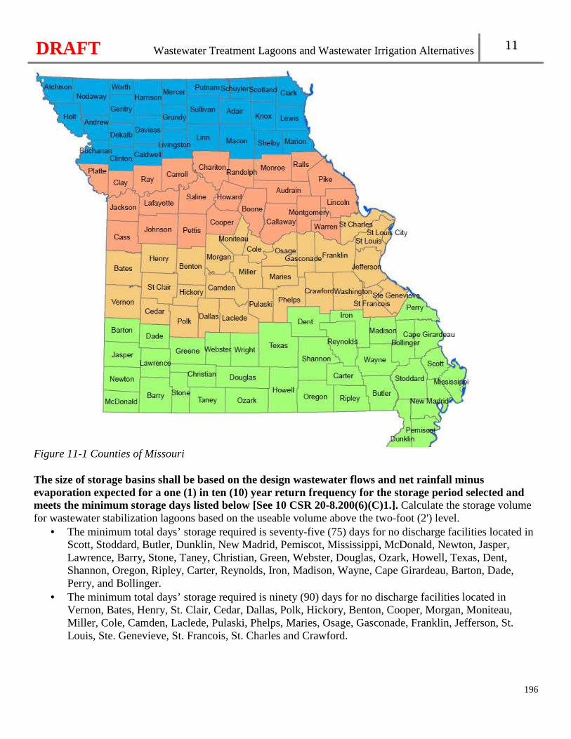
DRAFT Wastewater Treatment Lagoons and Wastewater Irrigation Alternatives 11
196
Figure 11-1 Counties of Missouri The size of storage basins shall be based on the design wastewater flows and net rainfall minus evaporation expected for a one (1) in ten (10) year return frequency for the storage period selected and meets the minimum storage days listed below [See 10 CSR 20-8.200(6)(C)1.]. Calculate the storage volume for wastewater stabilization lagoons based on the useable volume above the two-foot (2') level.
• The minimum total days’ storage required is seventy-five (75) days for no discharge facilities located in Scott, Stoddard, Butler, Dunklin, New Madrid, Pemiscot, Mississippi, McDonald, Newton, Jasper, Lawrence, Barry, Stone, Taney, Christian, Green, Webster, Douglas, Ozark, Howell, Texas, Dent, Shannon, Oregon, Ripley, Carter, Reynolds, Iron, Madison, Wayne, Cape Girardeau, Barton, Dade, Perry, and Bollinger.
• The minimum total days’ storage required is ninety (90) days for no discharge facilities located in Vernon, Bates, Henry, St. Clair, Cedar, Dallas, Polk, Hickory, Benton, Cooper, Morgan, Moniteau, Miller, Cole, Camden, Laclede, Pulaski, Phelps, Maries, Osage, Gasconade, Franklin, Jefferson, St. Louis, Ste. Genevieve, St. Francois, St. Charles and Crawford.
DRAFT Wastewater Treatment Lagoons and Wastewater Irrigation Alternatives 11
197
• The minimum total days’ storage required is one hundred five (105) days for no discharge facilities located in Cass, Johnson, Pettis, Platte, Jackson, Clay, Ray, Lafayette, Carroll, Saline, Chariton, Randolph, Howard, Boone, Callaway, Audrain, Monroe, Ralls, Pike, Lincoln, Warren, and Montgomery.
• The minimum total days’ storage required is one hundred twenty (120) days for no discharge facilities located in Atchison, Holt, Andrew, Nodaway, Worth, Gentry, DeKalb, Harrison, Daviess, Grundy, Mercer, Putnam, Sullivan, Linn, Macon, Adair, Schuyler, Scotland, Clark, Knox, Lewis, Shelby, Buchanan, Clinton, Caldwell, Livingston and Marion.
• Seasonal facilities. For facilities that only operate and generate flows from April through October season, a minimum storage capacity of forty-five days shall be provided. For facilities that only operate or generate flows from November through March, the minimum storage listed above is required [See 10 CSR 20-8.200(6)(C)1.E.].
Facilities should consider increasing the minimum storage days by at least thirty (30) days to ensure sufficient storage, if the facility:
• Employs a part-time operator, • leases the irrigation fields, • Has highly variable influent flow, or • Experienced discharges.
11.5.4 Application Rates and Soils Information The application rates for each individual site shall be based on topography, soils, geology, hydrology, weather, agricultural practice, adjacent land use and application method [See 10 CSR 20-8.200(6)(D)]. Unless a soils report has been completed and approved, the maximum application rate for typical domestic wastewater is twenty-four inches (24") of applied wastewater per year depending on soil characteristics. For higher application rates than twenty-four inches per year (24"/yr), submit a detailed site specific design proposal with additional soils and geologic information to justify the proposed design. See section 1.5 for additional information. Application rate. The application rate consists of an hourly application rate in inches per hour and daily, weekly and annual application rates in inches. Application of wastewater shall not be allowed during periods of ground frost, frozen soil, saturated conditions, or precipitation events. The following shall apply to design application rates [See 10 CSR 20-8.200(6)(D)]:
• The hourly application rate should not exceed the design sustained permeability rate except for short periods when initial soil moisture is significantly below field capacity. Do not exceed one-half (½) the design sustained permeability for slopes exceeding ten percent (10%) on the hourly rate.
• Base the daily and weekly application rates on soil moisture holding capacity, antecedent rainfall and depth to the most restrictive soil permeability. � For facilities applying at twenty-four inches per year (24”/yr), the application rate cannot
exceed one inch (1") per day and three inches (3") per week. � For facilities applying above twenty-four inches per year, the application rate cannot exceed
the values determined in the soils report and loading design. • Design the maximum annual application rate not to exceed ten percent (10%) of the design
sustained soil permeability rate for the number of days per year when soils are not frozen.
DRAFT Wastewater Treatment Lagoons and Wastewater Irrigation Alternatives 11
198
• The application rate of applied wastewater cannot result in runoff during or immediately following application.
Provide a description of the crops or vegetation to be grown for all systems in which vegetation is to be an integral part of the treatment system, including all surface irrigation systems. The use of wastewater for irrigation of truck farms growing vegetables will not be approved. Provide the following information:
• Compatibility of the crop with site characteristics; • Design hydraulic loading rates; • Cultivation and harvesting requirements; and • Crop management.
Consider the following in the design of the wastewater irrigation equipment:
• Minimize the formation of aersols with the selected spray application equipment; • The size of the pumping system and distribution system for the flow and operating pressure
requirements of the distribution equipment and the application restrictions of the soils and topography; • Make provisions for draining the pipes to prevent freezing if pipes are located above the frost line.
Soils Information. For facilities applying more than twenty four inches per year, see section 1.5 for Soils reports.
• The wetted application area should have a soil mantle of at least five feet (5') overlying any sand or gravel strata.
• Evaluate the topography of the site and adjacent land for areas of potential erosion. Consider the effects of both applied wastewater and storm runoff in site design and location. Special consideration should be given to the period of construction and system startup when vegetative cover may be lacking or not fully developed.
Calculate the total nitrogen and total phosphorus uptake in the expected vegetation for applications exceeding twenty-four inches (24”) per year.
• Nitrogen application rates cannot exceed the amount of nitrogen that can be utilized by the vegetation to be grown.
• Phosphorus can be present at levels that exceed the crop requirement when applications are based on nitrogen. An agronomic soil test is an index of phosphorus availability. Phosphorus tests include the Mehlich-3 soil test, the Bray-1 and the Olson P tests. Phosphorus application rates should not exceed one hundred eighty pounds per acre per year (180 lbs/acre/year).
Consider the type and influence of any industrial wastes contributed to the wastewater irrigation field. Typical domestic wastewater does not contain amounts of trace substances which are of concern for irrigation of wastewater under this rule. Introduction of substances, such as excess sodium, chlorides, boron or other constituents, can have an adverse impact on soils and vegetation. 11.5.5 Grazing Deferments The grazing of animals or harvesting of forage crops shall be deferred, as listed below, following wastewater irrigation, depending upon ambient air temperature and sunlight conditions[See 10 CSR 20-8.200(6)(E)]:
DRAFT Wastewater Treatment Lagoons and Wastewater Irrigation Alternatives 11
199
• Fourteen (14) days from grazing or forage harvesting during the period from May 1 to October 31 of each year;
• Thirty (30) days from grazing or forage harvesting during the period from November 1 to April 30 of each year; and
Grazing of wastewater irrigated land is not recommended for lactating dairy animals unless there has been a much longer deferment period. 11.5.6 Public Access Areas Disinfect wastewater prior to irrigation (not storage) in accordance with section 11.2 of this rule. The wastewater shall contain as few of the indicator organisms as possible and in no case shall the irrigated wastewater contain more than one hundred twenty-six (126) Escherichia coliform colony forming units per one hundred milliliters (126 cfu/ 100 ml) [See 10 CSR 20-8.200(6)(F)1.]; The public shall not be allowed into an area when irrigation is being conducted [See 10 CSR 20-8.200(6)(F)2.]; and For golf courses utilizing wastewater, all piping and sprinklers associated with the distribution or transmission of wastewater shall be color-coded and labeled or tagged to warn against the consumptive use of contents [See 10 CSR 20-8.200(6)(F)3.]. Recommended pipe coloring and labeling schemes are listed in Table 5.2. Utilize the best management practices recommended by the NRCS or University of Missouri Extension for surface irrigation on slopes greater than ten percent (10%). Best management practices include the installation of terraces, planting adequate vegetation to reduce runoff, and conducting soils tests at least once every five years(1/5yrs). 11.5.7 Alarm System An automatic notification alarm system shall be installed on the pressure monitoring system, on each pivot and pump system, and be capable of notifying an on-call operator when a fault occurs in the system [See 10 CSR 20-8.200(6)(G)]. Include on the alarm system pressure monitoring in case of line break or other malfunctions that causes leaks.
11.6 Subsurface Dispersal Systems 11.6.1 Site Restrictions Sites with seasonal high groundwater less than twenty-four (24) inches deep may require drainage improvements before being utilized. The design hydraulic conductivity at such sites is a function of the design of the drainage system.
DRAFT Wastewater Treatment Lagoons and Wastewater Irrigation Alternatives 11
200
Subsurface systems shall not be constructed in unstabilized fill and exclude soils that have been highly compacted and/or disturbed, such as old road beds, foundations, etc [See 10 CSR 20-8.200(7)(A)1.]. The vertical separation between the bottom of the trench and a limiting layer, including but not limit ed to, bedrock; restrictive horizon; or seasonal high water table, shall be [See 10 CSR 20-8.200(7)(A)1.]:
• No less than twenty-four inches (24”); • No less than twelve inches (12”) for systems dispersing secondary or higher quality effluent; or • No less than forty-eight inches (48”) where karst features are present unless the site can be
reclassified. Design dispersal trenches on slopes less than thirty percent (30%). Adequate surface drainage shall be provided where slopes are less than two percent (2%) [See 10 CSR 20-8.200(7)(A)3.]. Trenches may be required by the department to be sand-lined if the soils have severely diminished treatment capability due to excessive rock content; and Surface and subsurface water diversion is required where necessary, such as a curtain or perimeter drain [See 10 CSR 20-8.200(7)(A)4.]. Intercept subsurface lateral groundwater movement with a curtain or perimeter drain. A perimeter drain is completely surrounding the drip or leach field. A one to three sided curtain drain can also be used with the downhill side of the field left open.
11.7 Low Pressure Pipe (LPP) Subsurface Systems 11.7.1 Low Pressure Pipe Systems A low-pressure pipe (LPP) system is a shallow, pressure-dosed soil absorption system with a network of small diameter perforated pipes placed in narrow trenches. 11.7.2 Preliminary Treatment Subsurface systems shall be preceded by preliminary treatment; however secondary treatment is recommended. For design of a secondary treatment system, see Chapter 9 and section 11.2 [See 10 CSR 20-8.200(7)(B)]. 11.7.3 Design Loading rates shall not exceed the values assigned by the site and soil evaluation [See 10 CSR 20-8.200(7)(C)]. The LPP system shall be sized in accordance with the following equations, Equation 11-2 and Equation 11-3 [See 10 CSR 20-8.200(8)(A)1.]:
DRAFT Wastewater Treatment Lagoons and Wastewater Irrigation Alternatives 11
201
Equation 11-2: � ��
����
Equation 11-3: � ��
�����
Where: A = Minimum LPP soil treatment area (square feet) L = Minimum total length of LPP trench (feet) Q = Maximum daily sewage flow (gallons per day) LTAR = Long term acceptance rate (gallons per day per square foot). This is the lowest reported LPP soil loading rate between the soil surface and at least twelve inches (12”) below the specified LPP trench bottom or as approved by the department.
11.7.4 Distribution Network Design Design the distribution network and network configuration to include, but not limited to, pipe lengths and size, exterior control panel and alarm information, and calculations used to determine dose volume, orifice flow rates, dosing tank sizing and pump selection:
• All network piping and low pressure distribution piping and fittings with polyvinyl chloride (PVC) shall meet ASTM Standard D 1785 Schedule 40, 80, or 120 or equivalent rated to meet or exceed ASTM D2466 [See 10 CSR 20-8.200(8)(A)2.]. Supply watertight, rigid solid wall network piping including the main, sub-mains, and manifold. Properly place and support the pipes to prevent sagging and damage under normal loads and operating conditions.
• Manifold design shall address freeze protection while assuring uniform distribution and to minimize drain down of laterals into other laterals at a lower elevation between dosing events [See 10 CSR 20-8.200(8)(A)3.].
• Design lateral pipes to be three-quarter to two inches (3/4-2”) in diameter. • Design the system so there is no more than a five percent (5%) difference in flow rate between the
proximal and distal orifices on each distribution lateral. Design the system to ensure a minimum fluid velocity of two feet per second (2fps) is maintained in the main and manifold piping during dosing.
• Design the system so there no more than a five percent (5%) difference in the flowrate between two orifices in different distribution laterals that are to be dosed simultaneously during a single dosing event.
• Design laterals to include valves for adjustment of the operating distal pressure at startup to meet design specifications. Baseline measurements including reconciling the gallons per minute with the design, distal pressures/heights, and dose rates for future operations, maintenance, and monitoring should be measured and recorded.
• Provide accessible means of measuring design pressure or operating head for both initial baseline measurement and future monitoring of orifice clogging and other network operations.
• Provide a means of scouring or flushing distribution laterals. 11.7.5 Dosage The dosing frequency shall be based on the soils report and the dosing volume in zoned systems [See 10 CSR 20-8.200(8)(B)]. Establish a dosing volume based on the soil loading rate for each zone and to maximize treatment by control of the instantaneous loading rate and dose frequency.
DRAFT Wastewater Treatment Lagoons and Wastewater Irrigation Alternatives 11
202
• When a flow restrictive layer is present within twelve inches (12”) of the natural ground surface, the each delivered doses no greater than one-eighth (1/8) of the daily design flow and at least three (3) times the void volume of the laterals during each twenty-four (24) hour period.
• For facilities with restrictive layer greater than twelve inches( 12” of the natural ground surface, each delivered doses no greater than one-fourth (1/4) of the daily design flow and at least five (5) times the void volume of the laterals during each twenty-four (24) hour period.
When time dosing, select the volume and frequency to ensure that dosing events are spaced uniformly throughout a twenty-four (24) hour period to maximize resting between dosing events. Time dosed controls should prevent premature dosing when less than the daily dose volume is present in the dosing tank. 11.7.6 Orifices and Orifice Shielding Use orifices that are uniform, clean, and free of all drill cuttings. Stabilize lateral pipes when drilling orifices to prevent the pipes from moving and to ensure orifices are drilled perpendicular to the pipe. Orifice flow may be calculated using the following equation, Equation 11-4.
Equation 11-4:
Q = 11.79 x D2 x √h Where D = orifice diameter in inches; and h = pressure head in feet
Size orifices to be no less than one-eighth inch (1/8”) and spaced a maximum of six feet (6’)apart along the lateral. The orifice number and spacing shall be designed to provide a distribution of no more than six square feet per orifice with an orifice size of not less than one-eighth inch [See 10 CSR 20-8.200(8)(C)1.]. Space orifices a minimum of six inches from the end of the lateral. Specify the direction of orifices and the method of orifice shielding in the design and allow for uniform pressurization and depressurization of the laterals, and drain-back to prevent freezing. Specify in the design how the wastewater orifices will be dispersed from the orifices with uniform distribution.
• When orifices are positioned up in the twelve o’clock position, spray the wastewater stream against an orifice shield, gravel-less chambers, or similar device.
• When orifices are positioned down in the six o’clock position to facilitate draining after each dosing cycle, provide a mechanism to disperse the wastewater such as an orifice shield, a pad of gravel, or a splash plate.
When orifice shields are used, they must be strong enough to withstand the weight of the backfill and large enough to protect the orifice from being plugged by gravel. If effluent is to be sprayed upward against the top of gravel-less chambers, document and follow the manufacturer recommendations.
DRAFT Wastewater Treatment Lagoons and Wastewater Irrigation Alternatives 11
203
The distal pressure shall be designed and maintained at the end of each lateral to be no less than two feet (2 ft) (0.87 psi) when using three-sixteenth inch (3/16”) or larger diameter orifices, and no less than five feet (5 ft) (2.18 psi) when using orifices smaller than three-sixteenth inch (3/16”) [See 10 CSR 20-8.200(8)(C)2.]. Design Pressure dosed systems with elapsed time meters, event counters, or flow meters capable of measuring total flow to help determine flow rates and dose volumes.
• Design time dosed systems to have control panels with programmable timers, manual pump operation or hand- off- auto switches, test features, and as applicable, adjustable override settings.
• Adjustable override settings cannot exceed the daily design flow and the override volume cannot exceed the dosing design of the downstream component.
Include the dosing tank size and the pump, exterior control panel, and alarm information with the design, along with the settings or means used to accommodate the dose volume including any drain back to the dosing tank. 11.7.7 Trenches Design LPP trenches to follow the contour of the ground. Minimize compaction of the trench bottom, such as walking in the trench. Construct LPP trenches to be as level as possible, but in no case will the fall in a single trench bottom exceed one-half inch (1/2") in one hundred feet (100').
Design and construct LPP trenches with a minimum of four inches (4”) of backfill unless specified by the gravelless product manufacturer or professional engineer and specifically approved by the department with the facility plan. Design LPP trenches with clean pea gravel or other approved aggregate rock and graded or sized between three-eighths inch and one inch (3/8” and 1"). Crushed limestone and dolomite shall not be used. Fines are limited to one percent (1%) and do not use materials passing the No. 100 sieve;
• Other aggregate material may be used in LPP trenches, including but not limited to, tire chips or crushed glass when specified by the designer and specifically approved by the department;
• When aggregate is used, design the trench with a minimum of five inches (5”) of gravel below and a minimum of two inches (2”) of gravel above the LPP laterals;
• When aggregate is used, utilize a durable geotextile fabric to act as a barrier to permit passage of water and prevent passage of soil into the aggregate; and
• When gravelless dispersal trench products are used, design LPP trench in accordance with the manufacturer’s requirements.
11.8 Drip Dispersal Subsurface Systems Drip dispersal systems are designed and operated to allow the soil to provide final treatment of the wastewater prior to its introduction to groundwater. Dispersal and treatment occurs via physical, chemical and biological processes within the soil and through evapotranspiration and nutrient uptake by plant matter.
DRAFT Wastewater Treatment Lagoons and Wastewater Irrigation Alternatives 11
204
11.8.1 Preliminary Treatment Drip Dispersal systems shall be preceded by preliminary treatment that at a minimum meets the manufacturer’s recommendations; however secondary treatment technologies should be used. For design of a secondary treatment system, see Chapter 9 and section 11.2. Subsurface systems shall be preceded by preliminary treatment; however secondary treatment is recommended. For design of a secondary treatment system, see Chapter 9 and section 11.2 [See 10 CSR 20-8.200(7)(B)]. 11.8.3 Design Consider all factors influencing the infiltrative capacity of the soil and the ability of the soil and site to transport ground water away from the drip dispersal application area.
• It should be noted that the use of historical information from existing systems installed and operated in similar soils, with documented loading rates, landscape positions and design conditions similar to the proposed system may be applicable.
• Exclude soils that have been highly compacted and/or disturbed, such as old road beds, foundations, etc., when evaluating suitable.
The design wastewater loading is a function of precipitation, evapotranspiration, design hydraulic conductivity rate, nitrogen loading limitations, other constituent loading limitations, groundwater and drainage conditions, average and peak design wastewater flows, soil denitrification rates, and the rate of nitrogen uptake in site vegetation . Design the application rate in gallons per day per square foot (GPD/SF) based on the Soils Report submitted per Chapter 1. 11.8.4 Soils It is desirable to have a minimum depth of twenty inches (20”) of undisturbed soil above a restrictive horizon which may need to be increased as slope increases. This is necessary to provide adequate installation depth and buffer below the drip line. Even if a soil meets the depth requirements it may not be suitable due to the texture and/or structure. If a soil shows signs of wetness within a depth of twenty inches (20”) of the soil surface, it will most likely require a soil improvement practice such as an interceptor or drawdown drain. The location and size of the drains and buffers must be factored into the total area required for the drip dispersal system [See 10 CSR 20-8.200(9)(A)2.]. The drip dispersal system shall be sized with the minimum soil treatment area and total length, in accordance with the following equations, Equation 11-5 and Equation 11-6:
Equation 11-5:
� ��
���
Equation 11-6:
DRAFT Wastewater Treatment Lagoons and Wastewater Irrigation Alternatives 11
205
� ��
�����
Where: A = Minimum soil treatment area (square feet (sq. ft)) Q = Maximum daily wastewater flow (gallons per day (gpd)) HLR= Maximum hydraulic loading rate determined in the soils report (gpd/sq.ft) L = Minimum total length (ft)
11.8.5 Lines and Trenches The drip dispersal lines shall be placed at depths of six to ten (6-10”) inches below the surface [See 10 CSR 20-8.200(9)(B)1.]. The drip lines should be laid level and should run with the contour. Emitters and drip dispersal lines shall be placed on a two foot (2’) spacing to achieve even distribution of the wastewater and maximum utilization of the soil [See 10 CSR 20-8.200(9)(B)2.]. Space trenches at least five feet (5’) apart on centers. When trench spacing is greater than five feet (5’), a maximum effective area of up to five square feet (5 sq.ft.) of soil treatment area per foot of trench may be allowed. Design trenches with clean pea gravel or other approved aggregate rock and graded or sized between three-eighths inch and one inch (3/8” and 1"). Crushed limestone and dolomite shall not be used. Fines are limited to one percent (1%) and do not use materals passing the No. 100 sieve; Other aggregate material may be used in trenches, including but not limited to, tire chips or crushed glass when specified by the designer and approved in the facility plan by the department.

DRAFT
206
DRAFT Supplemental Treatment 12
Chapter 12: Supplemental Treatment
207
12.1 Post-Aeration Post-aeration may be needed for facilities using chlorine disinfection or having to meet a minimum dissolved oxygen effluent limit in the receiving waterbody. Post-aeration design may involve mechanical aeration, diffused air injection, or cascade type aeration. 12.1.1 Cascade Aeration For Cascade Type Aeration, the effluent aeration may be achieved through a turbulent liquid-air interface established by passing the effluent downstream over either a series of constructed steps, or a rough surface that produces a similar opportunity for transfer of dissolved oxygen to the effluent. Use the following equations, Equations 12-1 and 12-2, in the design of cascade type aerators:
Equation 12-1.
rn = (Cs-Ca)/(Cs-Cb) Where: r = Deficit ratio Cs = Dissolved oxygen saturation (mg/L) Ca = Dissolved oxygen concentration above the weir, assumed to be 0.0 mg/L Cb = Dissolved oxygen concentration in the effluent from the last or preceding step n = The number of equal size steps
Equation 12-2. r = 1 + (0.11) (ab) (1 + 0.046 T) (h)
Where: T = Water temperature (°C) h = Height of one (1) step (ft) a = 1.0 for effluents b = 1.0 for free fall and 1.3 for step weirs
The equation, Equation 12-1, for determining the number of steps is dependent upon equidistant steps; and, if unequal steps are used, determine transfer efficiencies for each separate step. Discharge the effluent over a sharp weir to provide for a thin sheet of wastewater. Consider preventing freezing. Install the final step of the cascade type aerator above normal stream flow elevation and protect the cascade aerator from erosion damage due to storm water drainage or flood/wave action. Provide multiple, variable speed pumps when pumping is necessary prior to discharge over the cascade aerator unless pumping from flow equalization.
DRAFT Supplemental Treatment 12
208
12.1.2 Other Modes of Post-Aeration Other methods of aeration may be utilized and will be evaluated on a case-by-case basis by the department.
12.2 Polishing Reactors Polishing reactors following lagoons and lagoon retrofits are being utilized to further reduce ammonia in the effluent. The reactor can be in a lagoon cell or in a separate basin. 12.2.1 General Provide an actual liquid depth between five feet (5’) or more than ten feet (10’) in a converted lagoon for facultative polishing reactors. Base the detention time on design flow and provide at least one day but no more than three days. Consider post-aeration following facultative polishing reactors to meet effluent dissolved oxygen requirements, due to the depletion of oxygen in facultative reactors. Install the influent line discharge below the liquid level of the reactor near the edge of the reactor embankment opposite the effluent structure to prevent short-circuiting and to provide maximum detention time. Provide a surface loading rate not to exceed seven hundred gallons per square foot per day (700 gpd/sq. ft). Sludge should not be present in the polishing reactor; however include provisions to facilitate sludge removal. 12.2.2 Design The process shall [See 10 CSR 20-8.210(2)(A)]—
• Be sized using less than two tenths a pound TKN per one thousand square feet per day (0.2 lbs TKN/1,000 ft2/day) for nitrification;
• Provide a minimum hydraulic retention time of three (3) hours; • Be based on actual influent characteristics into the reactor of;
� Removal of oil, grease, scum, grit and floating debris; and � Sized for a Biochemical Oxygen Demand loading of no more than forty eight pounds per one
thousand cubic feet per day (48 lbs BOD/1,000 cf/day); • Provide sufficient alkalinity with a minimum residual of fifty milligrams per liter (50 mg/L) in the
effluent or include chemical treatment; • Include cold weather provisions, including heaters, insulated covers, installation of temperature
controlled enclosures for above-ground components to prevent freezing and to ensure ammonia removal; and
• Provide a blower malfunction alarm able to notify the operator of alarm activations through audio-visual means.
DRAFT Supplemental Treatment 12
209
12.3 Filtration This section covers tertiary filtration used to remove suspended solids, nutrients, precipitated metals, inorganic ions, or synthetic organic compounds following conventional secondary treatment. 12.3.1 Additional Treatment Filtration systems shall be preceded with additional process, such as chemical coagulation and sedimentation or other acceptable process, when [See 10 CSR 20-8.210(3)(A)]:
• Permit requirements for suspended solids are less than ten milligrams (10 mg/l); • Effluent quality can be expected to fluctuate significantly; • Significant amounts of algae will be present; or • The manufacturer recommends.
12.3.2 General Design Provide a uniform filtration rate with a maximum of five gallons per minute per square foot (5 gpm/ft2) of surface area at design average flow. Provide equipment for the application of chemicals to the filter influent when necessary to enhance suspended solids removal and minimize biological growth within the media. Provide multiple unit operations for filtration to allow for continuous operation and operational variability for a system with an average design of one hundred thousand gallons per day (100,000 gpd) or greater. Provide an operating head loss less than ninety percent (90%) of the filter media depth. Provide each filter with a means of individually controlling the filtration rate. Provide effluent filter walls with adequate freeboard above the media, which do not protrude into the filter media. Apply the incoming flow uniformly to flooded media and in such a manner as to prevent media displacement. Cover the filter by a superstructure if necessary under local climatic conditions. Provide head room or adequate access to allow visual inspection of the operation as necessary for maintenance. Filtration systems shall be designed and constructed with [See 10 CSR 20-8.210(3)(B)1.]:
• Convenient access to all components and the media surface for inspection and maintenance without taking other units out of service;
• Enclosed controls and heating and ventilation equipment to control humidity; and • At least two (2) units with the capacity to handle the maximum wastewater flow with the largest
unit out of service. Equip filters with, as applicable and per manufacturer’s recommendations:
• Washwater troughs;
DRAFT Supplemental Treatment 12
210
• Flow control for effluent rate; • Measurement and positive control of backwash rate; • Means to shut off flow to filter during backwash; • Filter influent and effluent sampling points; • A manual override for automatic controls and each individual valve essential to the filter operation; • An underdrain system to uniformly distribute backwash water (and air, if provided) without clogging
from solids in the backwash water; • A method for periodic chlorination of the filter influent or backwash water to control slime growths; and • Pressure filters with convenient access to the media for treatment or cleaning.
Redundancy. Comply with Chapter 5 for filtration systems requiring power. Drain line. Equip each filter unit with a drain line at least six inches (6”) in diameter capable of draining the basin to the headworks. Flocculation. For filtration systems requiring coagulation and flocculation prior to the filtration, t he flocculation system shall [See 10 CSR 20-8.210(3)(B)2.]:
• Include chemical feed equipment to meet the system’s anticipated design flow and the ability to proportion chemical feed rates;
• Ensure the rapid dispersion and mixing of chemicals throughout the wastewater by providing mechanical or in-line static mixers; and
• Should include a minimum of two (2) flocculation basins, each with a: � Method to control the speed of the paddles; and � Drain line at least six inches (6”) in diameter capable of draining it to the head of the facility.
12.3.3 Backwash Provide enough capacity to backwash all filters. Provide a filter backwash rate of at least twenty gallons per square foot per minute (20 gpm/ft2) for fifteen (15) minutes, consistent with wastewater temperatures and the specific gravity of the filter media. When air scour is utilized, the backwash water rate can be reduced to fifteen gallons per minute per square foot (15 gpm/ft2) to allow the rate during air scour to be set at the optimum rate necessary to remove scoured particles from filter media surfaces. For cloth or disc filters, provide a backwash rate of at least six gallons per minute per square foot (6 gpm/ft2). The backwash rate may be reduced in accordance with the demonstrated capability of other methods, such as air scour, provided for cleaning of filter media or based on the manufacturer’s recommendations and test data.
• Provide two (2) or more backwash pumps so that the backwash flow rate is maintained with largest pump out of service.
• Proved duplicate backwash waste pumps, each with a capacity exceeding the design backwash rate by twenty percent (20%), as necessary to return backwash to the upstream unit operations.
Size the backwash control, or valves, as provided on the main backwash water line, so that the design rate of filter backwash is obtained with the control or valve settings for the individual filters approximately in a full open position. Provide a means for air release between the backwash pump and the wash water valve.
DRAFT Supplemental Treatment 12
211
Air scouring, if provided, should maintain three to five cubic feet per minute per square foot (3-5 cfpm/ft2) of filter area for two (2) to three (3) minutes preceding backwash at the design rate.
• Follow air scouring by a fluidization wash to restratify the media. • Place the air scour distribution system at or below the media and supporting bed interface; if placed at
the interface, design the air scour nozzles to prevent media from clogging the nozzles or entering the air distribution system.
• Do not use flexible hose which may collapse when not under pressure or relatively soft material which may erode at the orifice opening with the passage of air at high velocity for the air distribution system.
• Install a minimum of two ant-seepage collars six inches apart when the air delivery piping passes down through the filter media. Extend the anti-seepage collars three inches out from the pipe and continuously around the entire circumference of the pipe. Design to prevent short circuiting.
Provide water scour system flow rates in the range of half a gallon per minute per square foot to two gallons per minute per square foot (0.5-2.0 gpm/ft2) of filter surface area. Locate the bottom elevation of the channel or top of the weir above the maximum level of expanded media during back washing. In addition provide:
• A backwash withdrawal arrangement for optimizing removal of suspended solids; • A two-inch (2”) filter wall freeboard at the maximum depth of backwash flow above the filter media; • A level top or edge to provide a uniform loading in gpm per foot of channel or weir length; and • An arrangement of collection channels or weirs to provide uniform withdrawal of the backwash water
from across the filter surface. Disposal of Backwashed Material.
• Re-filter liquid filter backwash or return it to the wastewater treatment facility headworks or to the influent lift station.
• Pump solid filter backwash material to the influent lift station, the headworks, the digester, or to another location approved for processing.
12.3.4 Deep Bed Filters Install a deep bed filter structure with a minimum depth of eight and half feet (8.5’) as measured from the normal operating wastewater surface to the bottom of the underdrain system. The structure should provide for a minimum applied wastewater depth of three feet (3’) as measured from the normal operating wastewater surface to the surface of the filter media. Porous plate and strainer bottoms are not recommended. The design of manifold type filtrate collection or underdrain systems shall [See 10 CSR 20-8.210(3)(C)1.]:
• Minimize loss of head in the manifold and baffles; • Provide the ratio of the area of the underdrain orifices to the entire surface area of the filter media
at about 0.003; • Provide the total cross-sectional area of the laterals at about twice the area of the final openings; • Provide a manifold which has a minimum cross sectional area that is one and half (1.5) times the
total area of the laterals; and • Should assure even distribution of wash water and a uniform rate of filtration over the entire area of the
filter;
DRAFT Supplemental Treatment 12
212
Provide a means of surface washing unless other means of media agitation are available during backwash. Use disinfected wastewater effluent or filtered water as surface wash waters. Provide revolving type surface washers or an equivalent system. All rotary surface wash devices shall [See 10 CSR 20-8.210(3)(C)2.]:
• Provide a minimum wash water pressure of forty pounds per square inch (40 psi); • Provide adequate surface wash water to provide half to one gallon per minute per square foot
(0.5-1.0 gpm/ sq ft) of filter area. Install deep bed filters with:
• A loss of head gauge; • A rate of flow gauge; • A rate of flow controller of either direct acting, indirect acting, constant rate, or declining rate type; and • A rate of flow indicator on the main backwash water line, located so that it can be easily read by the
operator during the backwashing process. 12.3.5 Shallow Bed Filters The shallow bed filtration rate should not exceed one and a fourth gallons per minute per square foot (1.25 gpm/ sq ft) of filter area at average design flow. The shallow bed filter shall [See 10 CSR 20-8.210(3)(C)2.]:
• Not exceed two gallons per minute per square foot (2 gpms/ sq ft) of filter area at average design flow;
• Provide multiple unit operations to allow for continuous operability and operational variability; • Include filter media consisting of a series of up to eight inch filter increments having a minimum
total media depth of eleven inches (11”). For sand media, use an effective size in the range of 0.40 mm to 0.65 mm and a uniformity coefficient of 1.5 or less;
• Include inlet ports located throughout the length of the filter. • Provide an underdrainage system along the entire length of the filter so that filter effluent is
uniformly withdrawn without clogging outlet openings. • Have a traveling bridge mechanism which provides support and access to the backwash pumps
and equipment; is constructed of corrosion resistant materials; provides for consistent tracking of the bridge; provides support of the power cords; and initiates a backwash cycle automatically when a preset head loss through the filter media occurs.
12.3.6 Pressure Filtration For pressure filter operation. The design should provide for:
• Pressure gauges on the inlet and outlet pipes of each filter to determine loss of head; • A conveniently located meter or flow indicator with appropriate information to monitor each filter; • The means for filtration and backwashing of each filter individually, using a minimally complex
arrangement of piping; • Flow indicators and controls convenient and accessible for operating the control valves while reading
the flow indicators; and • An air release valve on the highest point of each filter.
Install the top of the wastewater collection channel or weir at least 18 inches above the surface of the media.
DRAFT Supplemental Treatment 12
213
Provide an underdrain system to uniformly and efficiently collect filtered wastewater and distribute the backwash water at a uniform rate, not less than fifteen gallons per minute per square foot (15 gpm/ sq ft) of filter area. Provide a means to observe the wash water during backwashing. Provide minimum sidewall heights of five feet (5’) for each filter. A corresponding reduction in sidewall height is acceptable where proprietary bottoms permit reduction of the gravel depth. Provide an accessible manhole when necessary to facilitate inspections and repairs. 12.3.7 Cloth/Disc Filters Media Design. The media shall [See 10 CSR 20-8.210(3)(E)1.]:
• Have an average pore size of cloth or disk filter media no larger than thirty (30) microns; • Follow the manufacturer's recommendations, considering frequent pressure changes to determine
thickness • Be disinfectant-resistant if the filter will be exposed to disinfectants; and • Be chlorine-resistant if the filter will be exposed to chlorine.
Filtration Rates and Hydraulics. The design shall:
• Base the filtration rate on the effective submerged surface area of the media. • Provide a maximum filtration rate for peak flow not more than six and half gallons per minute
per square foot (6.5 gpm/sq ft) of submerged media; and • Be able to treat the design flow rate with one (1) filter unit in backwash mode [See 10 CSR 20-
8.210(3)(E)2.]; and • Should account for variability if the submerged surface area of the media varies based on the operational
mode. Monitoring and Controls. Operate cloth or disk filters with an automatic control system that includes manual override capability. Provide each filter unit with a head loss gauge or readout. 12.3.8 Rotary Drum Filters Reserved. 12.3.9 Ultrafiltration Ultrafiltration uses a membrane barrier to exclude particles in the range of ten nanometers to one hundred nanometers (10-100 nm or 0.01-0.1 microns), including bacteria, viruses and colloids. Treatment of feed prior to the membrane is essential to prevent damage to the membrane and minimize the effects of fouling which greatly reduce the efficiency of the separation. Pre-treatment. Types of pre-treatment are often dependent on the type of feed and its quality, and include pH adjustment and coagulation.
• Appropriate sequencing of each pre-treatment phase is crucial in preventing damage to subsequent stages. Pre-treatment can even be employed simply using dosing points.
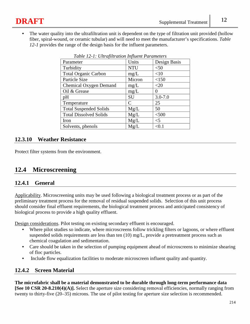
DRAFT Supplemental Treatment 12
214
• The water quality into the ultrafiltration unit is dependent on the type of filtration unit provided (hollow fiber, spiral-wound, or ceramic tubular) and will need to meet the manufacturer’s specifications. Table 12-1 provides the range of the design basis for the influent parameters.
Table 12-1: Ultrafiltration Influent Parameters
Parameter Units Design Basis Turbidity NTU <50 Total Organic Carbon mg/L <10 Particle Size Micron <150 Chemical Oxygen Demand mg/L <20 Oil & Grease mg/L 0 pH SU 3.0-7.0 Temperature C 25 Total Suspended Solids Mg/L 50 Total Dissolved Solids Mg/L <500 Iron Mg/L <5 Solvents, phenols Mg/L <0.1
12.3.10 Weather Resistance Protect filter systems from the environment.
12.4 Microscreening 12.4.1 General Applicability. Microscreening units may be used following a biological treatment process or as part of the preliminary treatment process for the removal of residual suspended solids. Selection of this unit process should consider final effluent requirements, the biological treatment process and anticipated consistency of biological process to provide a high quality effluent. Design considerations. Pilot testing on existing secondary effluent is encouraged.
• Where pilot studies so indicate, where microscreens follow trickling filters or lagoons, or where effluent suspended solids requirements are less than ten (10) mg/L, provide a pretreatment process such as chemical coagulation and sedimentation.
• Care should be taken in the selection of pumping equipment ahead of microscreens to minimize shearing of floc particles.
• Include flow equalization facilities to moderate microscreen influent quality and quantity. 12.4.2 Screen Material The microfabric shall be a material demonstrated to be durable through long-term performance data [See 10 CSR 20-8.210(4)(A)]. Select the aperture size considering removal efficiencies, normally ranging from twenty to thirty-five (20–35) microns. The use of pilot testing for aperture size selection is recommended.
DRAFT Supplemental Treatment 12
215
12.4.3 Screening Rate Select the screening rate to be compatible with available pilot test results and selected screen aperture size, but no more than five gallons per minute per square foot (5 gpm/sq ft) of effective screen area based on the maximum hydraulic flow rate applied to the units. The effective screen area is considered the submerged screen surface area less the area of screen blocked by structural supports and fasteners. The screening rate is that rate applied to the units with one (1) unit out-of-service. 12.4.4 Backwash All backwash shall be recycled for treatment [See 10 CSR 20-8.210(4)(B)]. Provide adequate backwash volume and pressure to assure maintenance of fabric cleanliness and flow capacity. Provide equipment for backwash of at least eight gallons per minute per linear foot (8gpm/lf) of screen length and sixty pounds per square inch (60 psi). Continuously supply backwash water by multiple pumps, including one (1) standby and obtain the backwash water from microscreened effluent. Control the rate of return of waste backwash water to treatment units so that the rate does not exceed fifteen percent (15%) of the design average daily flow rate to the treatment facility. Consider the hydraulic and organic load from waste backwash water in the overall design of the treatment facility. Where waste backwash water is returned for treatment by pumping, provide adequate pumping capacity with the largest unit out-of-service. Provide a means to measure backwash flow. 12.4.5 Appurtenances Provide each microscreen unit with automatic drum speed controls, provisions for manual override, a bypass weir with an alarm for use when the screen becomes blinded to prevent excessive head development, and means for de-watering the unit for inspection and maintenance. Segragate bypassed flows from water used for backwashing. Provide equipment for control of biological slime growths. Restrict the use of chlorine to those installations where the screen material is not subject to damage by the chlorine.
DRAFT Supplemental Treatment 12
216
12.4.6 Reliability Provide a minimum of two (2) microscreen units, each unit being capable of independent operation. Provide and maintain a supply of critical spare parts. Enclose all units and controls in a heated and ventilated structure with adequate working space to provide for ease of maintenance.
12.5 Chemical Addition Wastewater treatment uses chemicals in various forms to aid in sedimentation, nutrient removal, pH adjustment, corrosion and odor control, disinfection, and sludge/biosolids conditioning. Determine appropriate chemicals and feed ranges based on pilot studies or data from unit operations treating design flows of wastewater or domestic wastewaters of similar characteristics (organic levels, metal concentrations, etc., within twenty-five percent (25%) of proposed design). Comply with the requirements in section 5.7 for chemical handling. 12.5.1 Chemically Enhanced Sedimentation The criteria in the subsections above applies in addition to the following—
• Include low velocities downstream of flocculation, generally less than or equal to half a foot per second (0.5 fps), to avoid sheering the floc;
• Provide for increased sludge volume in the tanks, piping, and sludge handling equipment and impacts on digestion;
• Provide multiple coagulant and flocculant injection points in piping or channel before the sedimentation process;
• Rapidly and uniformly mix each chemical with the flow stream. Where separate mixing basins are provided, equip them with mechanical mixing devices and a detention period of at least thirty (30) seconds;
• Provide adjustable flocculation methods or equipment in order to obtain optimum floc growth, control deposition of solids, and prevent floc destruction.
• Provide a velocity through pipes or conduits from flocculation basins to settling basins of less than one and half feet per second (1.5 fps) in order to minimize floc destruction. Design entrances to settling basins to minimize floc shear.
• Provide automated control of coagulant and flocculant addition with dosing parameters based on design flow.
• Provide automated chemical dosing for pH adjustment of effluent to compensate for the potential pH reduction caused by some coagulants and flocculants, if such coagulants and flocculants are proposed or may be used.
• Consider the type and volume of sludge generated and sludge density and compaction in chemical sludge pumping designs.
12.5.2 Acids Acids shall [See 10 CSR 20-8.210(5)(A)]—
• Be kept in closed acid resistant shipping containers or storage units;
DRAFT Supplemental Treatment 12
217
• Be pumped in undiluted form from original containers through a suitable piping to the point of treatment or to a tightly sealed, vented and covered day tank not handled in open vessels; and
• Not be stored in the same area as sodium chlorite and sodium chlorate solutions or in chlorine feed or storage rooms or in any area that may be affected by a chlorine gas leak or vapors from chlorine solutions or compounds.
12.5.3 Carbon Dioxide Carbon dioxide gas is a colorless odorless gas. Provide recarbonation basin design with:
• A minimum detention time of twenty minutes; and • Two compartments, each with a depth of eight feet, as follows:
� A mixing compartment having a detention time of at least three minutes; and � A reaction compartment.
If a carbon dioxide solution is added and rapid mixing is provided, total detention time and basin depths may be reduced. Plants generating carbon dioxide from combustion shall have open top recarbonation tanks in order to dissipate carbon monoxide and carbon dioxide [See 10 CSR 20-8.210(5)(B)]. Give special consideration to building ventilation when open recarbonation tanks are housed in a building. Where liquid carbon dioxide is used, provide adequate precautions to prevent carbon dioxide from entering the facility from the feed lines or recarbonation process. Since liquid carbon dioxide is a cryogenic and a compressed gas, follow the recommendations of the Compressed Gas Association Inc. when specifying storage and feeding facilities. Provide a means for draining recarbonation basins and removing residuals. 12.5.4 Copper Sulfate Evenly distribute copper sulfate, when used, to continuously or periodically kill algae or other growths. Prevent copper concentrations more than the water quality standard in the facility effluent. Provide equipment for routine sampling to assure that over treatment does not occur. 12.5.5 Lime or Lime Soda Process Hydraulics. When split treatment is used, provide the bypass line sized to carry total facility flow, and an accurate means of measuring and splitting the flow; Chemical feed point. Lime should be fed directly into the rapid mix basin and provided 30 seconds detention time with adequate velocity gradients to keep the lime particles dispersed. Select coagulants that function in the high pH water encountered during lime addition. Aluminum sulfate (alum) in any of its forms does not function adequately at pH above 8.0.
DRAFT Supplemental Treatment 12
218
Where slaking of quick lime is proposed, consider the designed capacity of the treatment facilities. Manufactured lime slakers are generally sized for systems with designed flows of one thousand gallons per minute (1,000 gpm) or greater, and should not be proposed for a designed treatment capacity smaller than one thousand gallons per minute (1,000 gpm). Provide hydrated lime feeders for systems with a designed treatment capacity smaller than one thousand gallons per minute (1,000 gpm). Iron and manganese removal is not always incidental to lime addition. When the wastewater contains concentrations of iron or combined concentrations of iron and manganese of twenty milligrams per liter (20 mg/L) or greater or contains organic bound iron or manganese, additional treatment processes may be needed to assure adequate removal of the iron or manganese. 12.5.6 Phosphorus Removal Method. Addition of lime or the salts of aluminum or iron may be used for the chemical removal of soluble phosphorus. The phosphorus reacts with the calcium, aluminum or iron ions to form insoluble compounds. These insoluble compounds may be coagulated with or without the addition of a coagulant aid such as polyelectrolyte to facilitate separation by sedimentation or sedimentation followed by filtration. Dosage. Include the amount needed to react with the phosphorous in the wastewater, the amount needed to drive the chemical reaction to the desired state of completion, and the amount needed to overcome mixing or dispersion inefficiencies in the design chemical dosage. Avoid excessive chemical dosage. Chemical selection. Base the choice of lime or the salts of aluminum or iron on the wastewater characteristics and the economics of the total system.
• When lime is used it may be necessary to neutralize the high pH prior to subsequent treatment in secondary biological systems or prior to discharge in those flow schemes where lime treatment is the final step in the treatment process.
• Evaluate problems associated with lime usage, handling, and sludge production and dewatering. Filtration. Consider effluent filtration, such as with granular media filters or membrane separation technologies, where effluent phosphorus concentrations of less than half a milligram per liter (0.5 mg/L) are expected. 12.5.7 Safety and Hazardous Chemical Handling Comply with section 5.7. 12.5.8 Sludge Handling General. Consider the type and additional capacity of the sludge handling facilities needed when chemicals are used.
DRAFT Supplemental Treatment 12
219
De-watering. Base the design of de-watering systems, where possible, on an analysis of the characteristics of the sludge to be handled. Consider the ease of operation, effect of recycle streams generated, production rate, moisture content, de-waterability, final disposal and operating costs.
12.6 Carbon Adsorption Carbon adsorption involves the interphase accumulation or concentration of dissolved substances at a surface or solid-liquid interface by an adsorption process. Activated carbon, which is generally a wood or coal char developed from extreme heat, can be used in powdered form (PAC) or granular form (GAC). Carbon adsorption is used as the polishing process to remove dissolved organic material remaining in a wastewater treated to a secondary or advanced level. Activated carbon adsorption can also be used for dechlorination. 12.6.1 General Parameters with general application to design of carbon adsorption units are carbon properties, contact time, hydraulic loading, carbon particle size, pH, temperature and wastewater composition, including concentrations of suspended solids and other pollutants. Establish the adsorption characteristics of the type of carbon to be used. Such characteristics may be established using jar test analyses of various activated carbons in reaction with the waste to be treated. Determine adsorption isotherms for each form of carbon proposed for use. Consider the source and availability of replacement carbon. Where industrial wastes are present, perform pilot studies upon the selected carbon using the wastewater to be adsorbed to determine: breakpoint, exhaustion rate, contact time to achieve effluent standards; and if applicable, backwash frequency, pressure drop through the fixed bed columns, and the carbon regeneration capacity. Where strictly domestic waste is to be treated, data from similar full scale unit operations or pilot data will be acceptable. Normal carbon loss due to transportation between the columns and regeneration furnace is in the range of five to ten percent (5-10%) total carbon usage. Establish the rate at which carbon will lose adsorption capacity with each regeneration. Consider two carbon adsorption units operated in parallel or series for continuous operations. Provide sufficient capacity to allow for continuous operability of the carbon adsorption process. Provide for purging with chlorine or other oxidants as necessary for odor and bio-mass control. 12.6.2 Design The carbon adsorption unit should have a minimum height to diameter ratio of 2:1. Design to promote aerobic conditions in the filters. Provide a media depth of ten to forty feet (10’-40’).
DRAFT Supplemental Treatment 12
220
Base the flow rate on average daily flow. Upflow type filters are typically designed for a flow rate of 4-10 gpm/ sf and 3-5 gpm/sf for down flow type filters. Provide a minimum contact time of fifteen minutes (15 minutes). The normal detention time is fifteen to thirty-five minutes (15-35). Design the backwash system to remove all of the foreign material collected during the filter run. Design an upward flow of 12 to 20 gpm/sf, or a ten to fifty percent (10-50%) bed expansion. Provide for expansion of the bed by at least thirty percent (30%) when fixed-bed GAC carbon columns need to be backwashed to remove solids entrapped in the carbon material. Provide nonfixed bed carbon adsorption units, operating in upflow or downflow mode, with duplicate pumping units.
12.7 Side-Stream Nutrient Removal Reserved.
12.8 Diffusers Effluent multi-port submerged diffusers can be an acceptable means of ensuring mixing zones will avoid or allow no more than a minor detrimental effect in waters designated as habitat for a threatened or endangered species. A multi-port diffuser consists of a header pipe containing two or more ports (with or without risers) discharging in any orientation and may include wyes and other atypical arrangements. 12.8.1 General Provide computer dilution modeling (e.g. CORMIX) to justify that water quality standards will be met at the boundaries of acute and chronic mixing zones. Calibrate the computer dilution models to actual conditions in the field and include all critical flow and loading situations expected for the facility, including the low flow conditions on the waterbody in the analysis. For diffusers being installed at existing facilities, the existing outfall is to remain until the diffuser is installed and the existing outfall is to be removed once the diffuser is installed and operational. The diffuser header length (i.e., first port to last port) should not be greater than twenty-five percent (25%) of the stream width (or lateral distance corresponding to twenty-five percent (25%) of the cross-sectional area). The mixing zone shall not encroach on a drinking water intake, recreation area, or sensitive habitat, overlap the next downstream outfall, or occlude a downstream tributary [See 10 CSR 20-8.210(6)(A)1.]. Submit copies of the Summary of Design, facility plan and design drawings to US Fish and Wildlife Service and US Army Corps of Engineers. Demonstrate the system complies with the requirements of all other
DRAFT Supplemental Treatment 12
221
regulating agencies. Installation of the diffuser will require notificat ion and an Army Corps of Engineers permit [See 10 CSR 20-8.210(6)(A)2.]. 12.8.2 Diffuser Design Criteria Identify the pipeline from the treatment facility to the receiving waterbody on the plans. The pipeline shall be contained within approved property boundaries or easements [See 10 CSR 20-8.210(6)(B)1.]. Identify the specific location of the submerged diffuser with a shoreline marker. Locate the feeder pipeline and diffuser header such that the pipeline can be accessed for monitoring and maintenance. Access points to the receiving water should be within close proximity to the diffuser, preferably upstream. Design the diffusers to compensate for the geomorphology along the proposed outfall route and diffuser site including stability and mobility of the bottom, anticipated scour and deposition, flood conditions, and other potential hazards to the diffuser (e.g., dredging, recreation or commercial uses, seasonal debris loads). Specify a durable material that will provide a consistent cross section throughout its service life for diffuser pipe and ports. Ports constructed of carbon steel, stainless steel, and high-density polypropylene have demonstrated suitable service for multi-port diffusers. When carbon steel is used, provide a coating or corrosion allowance. Design a diffuser pipe velocity of at least two feet per second (2 fps) at peak flows. Individual port velocities will exceed two feet per second (2 fps) at average dry weather flows. Maximum port velocity shall not exceed fifteen feet per second (15 fps) [See 10 CSR 20-8.210(6)(B)2.].
12.9 Electrocoagulation Electrocoagulation is a proven and acceptable means of wastewater treatment, especially with industrial wastewater. However, only limited use has been made of electrocoagulation for domestic or municipal wastewater treatment, both in Missouri and the United States as a whole. Electrocoagulation systems will be evaluated on a case-by-case basis. Design standards, operating data, and experience for this process are not well established for use in domestic wastewater. Therefore, base the design of these systems on experience at similar full scale installations or thoroughly documented prototype testing with the particular wastewater.
12.10 Reverse Osmosis Reverse Osmosis is a proven and acceptable means of wastewater treatment, especially with industrial wastewater. However, only limited use has been made of reverse osmosis for domestic or municipal wastewater treatment, both in Missouri and the United States as a whole. Reverse Osmosis systems will be evaluated on a case-by-case basis. Design standards, operating data, and experience for this process are not well established. Therefore, base the design of these systems on experience at similar full scale installations or thoroughly documented prototype testing with the particular wastewater.

DRAFT
222
DRAFT Manure Storage Design Regulations 13
Chapter 13: Manure Storage Design Regulations
223
13.1 Permit Application Documents Applications for a construction permit for earthen basins need to have one (1) set of documents described in this section for department approval as part of the construction permit application process. Applicants who are not constructing earthen basins and are seeking an operating permit should develop and maintain these documents and submit those required in 10 CSR 20-6.300. The engineering documents should provide the basic information, present design criteria and assumptions, examine alternate systems, where appropriate, and provide plans and specifications. The documents should also include process description, sizing, data, controlling assumptions, and considerations for the functional operation of an animal waste management system. All engineering documents shall be prepared by or under the direct supervision of a registered professional engineer licensed to practice in Missouri [See 10 CSR 20-8.300(2)]. The department will not examine the adequacy or efficiency of the structural, mechanical, or electrical components of the animal waste management systems, only adherence to rules and regulations.
13.1.1 Engineering Report The following paragraphs list requirements for the content of the project engineering report to be submitted to the department for review and approval: Title page. Title of project, date, operation’s name and address, name and address of firm preparing the report, and seal and signature of the engineer. Narrative project summary. Provide an explanation of any existing conditions at the operation and a summary of the proposed modifications to the operation. Summary of design. Include the design data, calculations, all assumptions, and all relevant information used to justify the design. Include the following items:
• Each animal type and number within the production area, the maximum design animal capacity, and the average weight for each animal type;
• A detailed explanation of the process by which manure is deposited, handled, managed, and transferred within the operation;
• Calculations showing the estimated annual amount of manure generated at the production area and wastewater flows with average rainfall. Where possible, base design manure volume on past operating records or operating data from facilities with similar feed inputs and animal characteristics. Include documentation of these volumes. If operating data is not available, estimate the design manure volume using the most recent edition of a research based reference and include the reference name, edition, and data;
• Design calculations justifying the size of manure storage structures. This includes safety volume, storage volume, total storage capacity, design storage period, and treatment volume. For waste treatment lagoons, base the volume of treatment on the geographical region of the proposed structure and calculate the volume using the most recent edition of a research-based reference including the reference name, edition, and data;
• Stage-storage tables on at least one-foot (1') increments for all earthen basins with design operating depths (elevation of lower and upper pumpdown levels) clearly identified;
DRAFT Manure Storage Design Regulations 13
224
• Methods of collection, treatment, and disposal of all domestic wastewater flows associated with the operation; and
• If applicable, justifications for constructing an uncovered manure storage structure. Covered storages are preferred due to the lower risk of environmental damage from excessive rainfall.
Soils report/soils information. Provide county soil survey information including a soils map showing approximate boundaries of the different soils, soil series names, soil textural classes, and physical properties to define the characteristics of soils in the production areas. Include any soil boring or test pit logs in the report; and Operation and maintenance plan. Provide an operation and maintenance plan to explain the key operating procedures minimally addressing the operation and maintenance of mechanical equipment. 13.1.2 General Layout Drawings Include both an aerial and a topographic map or drawing that shows the spatial location and extent of the production area. Include a scale preferably of one inch (1") per one thousand feet (1,000'), a north directional arrow, a fixed geographic reference point, and the date the drawing or map was completed. Include the following on each drawing or map:
• All confinement barns, open lots, manure storage, and control structures, along with the other various components of the operation such as areas designated for stockpiling, composting, and for the management of animal mortalities;
• The source of the operation’s water supply and all wells within three hundred feet (300') of the production area; and
• The location of all surface water features within the boundaries or immediately adjacent to the production area.
13.1.3 Construction Plan Drawings Include the following on plan drawings:
• The name of the operation and the scale in feet, a north directional arrow, and the signed and dated engineer’s seal;
• Clear and legible plans drawn to a scale with all necessary information plainly shown. The size of the plans generally should not be larger than thirty inches by forty-two inches (30" × 42"), with a preference for smaller sizes;
• Locations of all test borings with date of site investigation; • Detail plans shall consist of plan views, elevation views, profiles, sections, and supplementary views
which, together with the specifications and general layouts, provide the working information for the construction of the containment facilities [See 10 CSR 20-8.300(3)(C)4.]; and
• Dimensions and relative elevations of manure storage structures, the location of components of the animal waste management system, alignment and size of piping, and profiles of piping with grades.
13.1.4 Specifications Specifications shall accompany the plans [See 10 CSR 20-8.300(3)(D)].
DRAFT Manure Storage Design Regulations 13
225
13.2 Location 13.2.1 Protection from Flooding Manure storage structures, confinement buildings, open lots, composting pads, and other manure storage areas in the production area shall be protected from inundation or damage due to the one hundred- (100-) year flood [See 10 CSR 20-8.300(3)(A)]. 13.2.2 HEADING The minimum setback distances from manure storage structures, manure storage areas, confinement buildings, open lots, or mortality composters shall be as follows [See 10 CSR 20-8.300(3)(B)]:
• Ten feet (10') to public water supply pipelines; • Fifty feet (50') to property lines; • Fifty feet (50') to public roads; • One hundred feet (100') to wetlands, ponds, or lakes not used for human water supply; • One hundred feet (100') to gaining streams (classified or unclassified; perennial or intermittent); • Three hundred feet (300') to human water supply lakes or impoundments; and • Three hundred feet (300') to losing streams (classified or unclassified; perennial or intermittent)
and sinkholes. 13.2.3 HEADING Distances from earthen basins shall be measured from the outside edge of the top of the berm [See 10 CSR 20-8.300(3)(C)]. 13.2.4 HEADING Separation distance from wells for manure storage structures or confinement buildings shall be in accordance with 10 CSR 23-3.010 [See 10 CSR 20-8.300(4)(D)].
13.3 Manure Storage Structure Sizing 13.3.1 No Discharge Requirement All manure storage structures shall be designed as no-discharge [See 10 CSR 20-8.300(4)(A)]. 13.3.2 Design Storage Period The minimum design storage period for manure storage structures shall be as follow [See 10 CSR 20-8.300(4)(B)]:
• The recommended design storage period is three hundred sixty-five (365) days.
DRAFT Manure Storage Design Regulations 13
226
• The minimum design storage period for liquid manure, solid manure, and dry process waste to be land applied is one hundred eighty (180) days.
• The minimum design storage period for solid manure and dry process waste to be sold or used as bedding is ninety (90) days.
• The minimum design storage period for waste treatment lagoons without an impermeable cover is three hundred sixty-five (365) days.
13.3.3 HEADING New Class I swine, veal, or poultry operations shall evaluate proposed uncovered manure storage structures in accordance with applicable federal regulation as set forth in 40 CFR 412.46(a)(1), November 20, 2008, which is hereby incorporated by reference, without any later amendments or additions, as published by the Office of the Federal Register, National Archives and Records Administration, Superintendent of Documents, Pittsburgh, PA 15250-7954 [See 10 CSR 20-8.300(4)(C)]. 13.3.4 Sizing Manure Storage Structures The structure shall be designed to hold all inputs, between the upper and lower operating levels, anticipated during the design storage period. This typically includes [See 10 CSR 20-8.300(4)(D)1.]:
• Animal manure; • Bedding material; • Wash water; • Flush water (excluding recycled flush water); • Cooling water for animals or from equipment; and • Runoff from pervious and impervious areas, due to average rainfall.
Uncovered liquid storage structures shall also include [See 10 CSR 20-8.300(4)(D)2.]:
• R-E from the surface of the structure, held between the operating levels; and • Safety volume above the upper operating level.
Tanks and pits shall also include six inches (6") of depth below the lower operating level for incomplete removal allowance [See 10 CSR 20-8.300(4)(D)3.]. Earthen basins shall also include [See 10 CSR 20-8.300(4)(D)4.]:
• At least one foot (1') of freeboard or two feet (2') for structures that receive storm water from open lots larger than the surface area of the storage structure;
• Two feet (2') of permanent liquid depth below the lower operating level. Anaerobic treatment volume greater than two feet (2') satisfies this requirement;
• Sludge accumulation volume; and • Treatment volume below the lower operating level for anaerobic treatment lagoons.
DRAFT Manure Storage Design Regulations 13
227
13.4 Construction of Earthen Basins 13.4.1 Geohydrologic Evaluation A geohydrologic evaluation of the proposed earthen basin prepared by the Missouri Geological Survey shall be submitted[See 10 CSR 20-8.300(5)(A)]. The design of all structures shall be sufficient to address the site limitations identified by the Missouri Geological Survey and should be discussed in the engineering report. Collapse potential rating. If the geohydrologic evaluation gives a severe rating for collapse potential, an earthen basin shall not be used [See 10 CSR 20-8.300(5)(A)1.]. Overall geologic limitations rating. Sites that have a severe rating for the overall geologic limitations but a slight or moderate collapse potential will be reviewed on a case-by-case basis. The department may require artificial liners or additional geotechnical exploration and design implementation and/or post-construction testing in these situations. 13.4.2 Detailed Soils Investigation Perform a detailed soils investigation to substantiate feasibility and to determine the quantity and quality of soil materials on-site and from a borrow area for use in the basin and/or liner. Use test pits, split spoon (barrel), or thin-walled tube sampling or a combination of these techniques depending on the total area of investigation and the depth to which exploration is needed. The following information, in whole or in part, is required [See 10 CSR 20-8.300(5)(B)]:
• Atterburg limits; • Standard proctor density (moisture/density relationships); • Coefficient of permeability (undisturbed and remolded); • Depth to bedrock; • Particle size analysis; and • Depth to groundwater table.
Present information gathered from the investigation on a map drawn to scale including field slopes, location, and other surface features. Use soil profiles of the representative soil material. Include copies of original borings and other soil test logs and incorporate an interpretation of the collected data into the report. Discuss any site constraints and the means of overcoming them in construction. 13.4.3 Shape and Location Shape of cells. The shape of all cells shall be such that there are no narrow or elongated portions or islands, peninsulas, or coves [See 10 CSR 20-8.300(5)(C)1.]. Constant elevation of floor. The floor of the structure shall be a consistent elevation with finished elevations not more than three inches (3") above or below the average elevation of the floor [See 10 CSR 20-8.300(5)(C)2.].
DRAFT Manure Storage Design Regulations 13
228
Distance to groundwater and bedrock. The floor of the basin shall be at least four feet (4') above the groundwater table or the water table as modified by subsurface drainage and at least two feet (2') above bedrock [See 10 CSR 20-8.300(5)(C)3.]. For perched water tables, a curtain drain with a positive outlet may be installed around the structure. 13.4.4 Slope Inner and outer berm slopes shall not be steeper than three to one (3:1), horizontal to vertical and inner slopes not be flatter than four to one (4:1) [See 10 CSR 20-8.300(5)(D)]. Design long outer slopes to be flatter than three to one (3:1) to assist in safe mowing of vegetation 13.4.5 Berm Construction and Width Construction specifications shall include the following [See 10 CSR 20-8.300(5)(E)]:
• Compact soil used in constructing the basin floor (not including clay liner) and berm cores to between two percent (2%) below and four percent (4%) above the optimum water content and compacted to at least ninety percent (90%) standard proctor density.
• Use lifts for berm construction not exceeding twelve inches (12") with a maximum rock size not exceeding one-half (1/2) of the thickness of the compacted lift.
• Construct the top of the berm to a minimum width of eight feet (8'); for fill heights from fifteen to twenty feet (15'–20'), use a minimum top width of ten feet (10'); for fill heights from twenty to twenty-five feet (20'–25'), use a minimum top width of twelve feet (12').
13.4.6 Emergency Spillway To prevent overtopping and cutting of berms, an emergency overflow shall be provided that [See 10 CSR 20-8.300(5)(F)]:
• Has a minimum bottom width of ten feet (10') and a minimum depth of one foot (1'); and • Is compacted and vegetated or otherwise constructed to prevent erosion due to possible flow.
13.4.7 Compacted Clay Liner Soils information. The soils used for construction of an earthen basin liner shall meet the following minimum specifications [See 10 CSR 20-8.300(5)(G)1.]:
• Be classified under the Unified Soil Classification System (ASTM D2487) as CL, CH, GC, or SC; • Allow more than fifty percent (50%) passage through a Number 200 sieve; • Have a liquid limit equal to or greater than thirty (30); • Have a plasticity index equal to or greater than twenty (20); and • Have a coefficient of permeability equal to or less than 1 × 10⁻⁷ centimeters per second (cm/sec)
when compacted to ninety percent (90%) of standard proctor density with the moisture content between two percent (2%) below and four percent (4%) above the optimum moisture content.
Liner construction. Compacted clay liners shall be constructed to meet the following minimum specifications [See 10 CSR 20-8.300(5)(G)2.]:
DRAFT Manure Storage Design Regulations 13
229
• Be scarified and compacted to between two percent (2%) below and four percent (4%) above the optimum water content and be compacted to at least ninety percent (90%) standard proctor density.
• Be raised in lifts not exceeding six inches (6") with a maximum rock size not exceeding one-half (1/2) of the thickness of the compacted lift.
• Be maintained at or above the optimum water content until the basin is prefilled with water. • Have a minimum thickness of twelve inches (12").
Permeability. All earthen basins shall be sealed so that seepage loss through the seal is minimized. The basin seal shall [See 10 CSR 20-8.300(5)(G)3.]:
• Cover the floor and extend up the inner slope to where the side slope intersects with the top of the berm.
• Have a design permeability of the basin seal not exceeding 1.0 x 10⁻⁷ cm/sec. The following equation shall be used to determine minimum seal thickness for soils which have a coefficient of permeability greater than 1 × 10⁻⁷ centimeter per second [See 10 CSR 20-8.300(5)(G)]: Equation 13-1:
t = (H×K)/ 5.4 × 10⁻⁷cm/sec
Where: K = permeability coefficient of the soil in question; H = head (maximum water level depth) of water in the basin; and t = thickness of the soil seal. 13.4.8 Prefilling Prefill the basin in order to protect the liner, prevent weed growth, reduce odor, allow measurement of percolation losses, and maintain moisture content of the seal. If the clay liner is allowed to dry, the liner must be scarified and recompacted as described [See 10 CSR 20-8.300(6)(H)]. 13.4.9 Protection of Berms Exlude livestock, burrowing animals, and woody vegetation from basins to protect the integrity of the berms and liners. Assure that a good vegetative cover is established on lagoon berms to minimize erosion. The inner berms should be seeded down to the upper operating level of the structure. Rip-rap or some other acceptable method of erosion control is required as a minimum around all piping entrances and exits; for aerated cell(s), on the slopes and floor in the areas where turbulence will occur; and for protection from wave action for basins with a surface area greater than five (5) acres [See 10 CSR 20-8.300(5)(H)].
DRAFT Manure Storage Design Regulations 13
230
13.4.10 HEADING If alternative liners are used, permeability, durability, and integrity of the proposed materials must be satisfactorily demonstrated for anticipated conditions [See 10 CSR 20-8.300(5)(I)]. 13.4.11 Depth Gauges A permanent depth measurement gauge or marker shall be installed and maintained in the basin in easily readable one-foot (1') or smaller increments with the lower, upper, and emergency spillway levels clearly displayed [See 10 CSR 20-8.300(5)(J)]. 13.4.12 Piping Fill around pipes installed through embankments shall be compacted to prevent seepage and pressurized piping must be valved [See 10 CSR 20-8.300(5)(K)]. 13.4.13 Safety Consideration shall be given for safety in using open storage structures including the use of prevention and recovery components [See 10 CSR 20-8.300(5)(L)]. 13.4.14 Operation and Maintenance An operation and maintenance plan is required addressing the major components of the animal waste management system [See 10 CSR 20-8.300(5)(M)].
13.5 Construction of Tanks and Pits Construction of tanks and pits shall meet the requirements in the following subsection below [See 10 CSR 20-8.300(6)]. 13.5.1 Soils and Foundation Conduct a thorough site investigation to determine the physical characteristics and suitability of the soil and foundation for the fabricated storage structure. Position the floor of the below-ground storage tanks two feet (2') above the groundwater table [See 10 CSR 20-8.300(6)(A)]. 13.5.2 HEADING Allow one foot (1') of depth at the top of covered structures for agitation and/or ventilation [See 10 CSR 20-8.300(6)(B)].
DRAFT Manure Storage Design Regulations 13
231
13.5.3 Depth Gauges Include a permanent depth measurement gauge or marker that is easily readable at one-foot (1') or smaller increments for uncovered tanks and pits [See 10 CSR 20-8.300(6)(C)]. 13.5.4 Footing Drains/Perimeter Tiling Use perimeter tiling and granular backfill for below-ground pits [See 10 CSR 20-8.300(6)(D)]. 13.5.5 HEADING Locate tank and pit footings at or below the maximum frost depth [See 10 CSR 20-8.300(6)(E)]. 13.5.6 HEADING Design concrete and steel features according to published guidelines [See 10 CSR 20-8.300(6)(F)]. 13.5.7 Watertight Requirement Design and construct tanks and pits to be watertight [See 10 CSR 20-8.300(6)(G)].
13.6 Construction of Solid Manure Components The following requirements in the subsections below shall be met when constructing poultry buildings, open lots, stacking pads, stacksheds, and other similar structures [See 10 CSR 20-8.300(7)]. 13.6.1 HEADING Divert surface water away from animal confinement areas and buildings [See 10 CSR 20-8.300(7)(A)]. 13.6.2 Floors and Pads Construct the base of covered and uncovered lots, poultry buildings, and other solid manure storage areas of concrete or other rigid, essentially watertight materials or from a firm, compacted, earthen base of Unified Soil Classification System (USCS) class CH, MH, CL, GC, or SC soils [See 10 CSR 20-8.300(7)(B)]. The base can utilize existing consolidated soils if there is one (1) continuous foot of soil classified as class CH, MH, CL, GC, or SC in the Unified Soil Classification System (USCS) within four feet (4') of the proposed earthen floor [See 10 CSR 20-8.300(7)(B)1.]. The finished earthen floor shall be a minimum of two feet (2') above groundwater table; and be at least two feet (2') above bedrock [See 10 CSR 20-8.300(7)(B)2.].
DRAFT Manure Storage Design Regulations 13
232
13.6.3 HEADING Uncovered solids storage areas must also meet the following [See 10 CSR 20-8.300(7)(C)]:
• Have an overall slope between two percent (2%) and four percent (4%) for unpaved lots; • Be maintained in a way that prevents ponding; and • Have a runoff collection structure that meets the requirements of this rule.
13.7 Design and Construction of Pipelines, Pump Stations, and Land Application Systems 13.7.1 General Design of pipelines shall be based on the following requirements [See 10 CSR 20-8.300(8)(A)]:
• Insure the storage/treatment facilities can be emptied within the time limits stated in the nutrient management plan;
• Design to convey the required flow without plugging, based on the type of material and total solids content;
• Install at a depth sufficient to protect against freezing; • Install with appropriate connection devices to prevent contamination of private or public water
supply distribution systems and groundwater; • Have pumps sized to transfer material at the required system head and volume; • Install at sufficient depth below the natural floor of the stream bed to protect the pipe. The top of
the pipe should be a minimum of three feet (3') below the natural stream floor and as nearly perpendicular to the stream flow as possible. Aerial pipeline crossing of streams shall be in accordance with section 2.7 [See 10 CSR 20-8.300(8)(A)6.];
• Encase when buried under roads; and • Separate from potable water lines at least ten feet (10') horizontally and at least eighteen inches
(18") below the base of the water line. 13.7.2 Gravity Pipelines Design of pipelines shall be based on the following requirements [See 10 CSR 20-8.300(8)(B)]:
• Use a minimum slope of one percent (1%) for four inch (4") pipe, six-tenths percent (0.6%) for six inch (6") pipe, and four-tenths percent (0.4%) for eight inch (8") pipe.
• Design with clean-outs at a maximum interval of three hundred feet (300') and with maximum horizontal curves of ten (10) degrees) at pipe joints; and
• Design with a minimum of two (2) valves in series. 13.7.3 Force Mains and Pressure Pipes Design velocities shall be between three (3) and six (6) feet per second [See 10 CSR 20-8.300(8)(C)].
DRAFT Manure Storage Design Regulations 13
233
13.7.4 Testing Hydro-pressure tests shall be made only after the completion of backfilling operations and for a minimum of one (1) hour using a minimum test pressure of the maximum system operating pressure [See 10 CSR 20-8.300(8)(D)]. 13.7.5 Pump Stations Water supply protection. Manure pump stations shall not be connected to a potable water supply and shall be located at least three hundred feet (300') from any potable water supply well [See 10 CSR 20-8.300(8)(E)1.]. Alarm systems. Alarm systems are required for pumping stations that are activated in cases of power failure, pump failure, or any cause of high water in the wet well [See 10 CSR 20-8.300(8)(E)2.]. 13.7.6 Land Application Systems Land application systems shall be designed with [See 10 CSR 20-8.300(8)(F)]:
• Spray application equipment specified that minimizes the formation of aerosols; • The pumping system and distribution system sized for the flow and operating pressure
requirements of the distribution equipment and the application restrictions of the soils and topography;
• Provisions made for draining the pipes to prevent freezing, if pipes are located above the frost line;
• A suitable structure provided for either a portable pumping unit or a permanent pump installation; the intake to the pumping system providing the capability for varying the withdrawal depth; the intake elevation maintained twelve to twenty-four inches (12"–24") below the liquid elevation; the intake screened so as to minimize clogging of the sprinkler nozzle or distribution system orifices; and, for use of a portable pump, a stable platform and flexible intake line with flotation device to control depth of intake;
• Thrust blocking of pressure pipes; and • An automatic pump or engine shut-offs in case of pressure drop.
13.8 General System Details 13.8.1 Mechanical Equipment Mechanical equipment shall be used and installed in accordance with manufacturers’ recommendations and specifications and major mechanical units installed under the supervision of the manufacturer’s representative [See 10 CSR 20-8.300(9)(A)].
DRAFT Manure Storage Design Regulations 13
234
13.8.2 Potable Water Supply Protection No piping or other connections shall exist in any part of the animal waste management system which, under any conditions, might cause the contamination of a potable water supply [See 10 CSR 20-8.300(9)(B)].
13.9 Mortality Management Class I operations shall not use burial as a permanent mortality management method to dispose of routine mortalities [See 10 CSR 20-8.300(10)].

DRAFT
235
DRAFT Design Requirements for Agrichemical Facilities 14
Chapter 14: Design Requirements for Agrichemical Facilities
236
This guide applies to the design and construction of or at an agrichemical facility. All new operations shall be designed to be no discharge [See 10 CSR 20-8.500(1)].
14.1 Exceptions The following exceptions in the subsections below apply to agrichemical facilities. 14.1.1 HEADING This guide does not apply to facilities storing or handling less than the regulated quantities of agrichemicals unless an on-site evaluation by the department determines that compliance with the regulations is necessary to protect the environment. The prohibition of storing bulk liquid fertilizer i n a mobile container for more than thirty (30) days shall not apply to barges and rail cars used solely for transporting liquid fertilizer from chemical production facilities to retail or wholesale facilities [See 10 CSR 20-8.500(2)(A)]. 14.1.2 HEADING Liquid fertilizer storage tanks that were in use prior to January 13, 1992, having a storage capacity greater than forty thousand (40,000) gallons are exempt from the requirement of installing a liner underneath the tank itself. The prohibition of burying pipes used for transferring full strength agrichemicals shall not apply to piping used solely for the loading and unloading of liquid fertilizer from barges and rail cars. These pipes shall be pressure tested on a yearly basis to certify the integrity of the pipes. Records of the pressure testing shall be kept on file at the facility and made available to department personnel upon request [See 10 CSR 20-8.500(2)(B)]. 14.1.3 HEADING The prohibition of storing bulk liquid fertilizer in a mobile container for more than thirty (30) days does not apply to barges and rail cars used solely for transporting liquid fertilizer from chemical production facilities to retail or wholesale facilities.
14.2 Engineering Report An engineering report is required for all facilities required to submit an application for a construction permit and is recommended for all facilities [See 10 CSR 20-8.500(3)]. The engineering report assembles basic information, presents design criteria and assumptions, examines alternate projects with preliminary layouts and cost estimates, offers a conclusion with a proposed project for client consideration, and outlines official actions and procedures to implement the project. Engineering reports contain the following information in the subsections below and other pertinent information and may be combined with other engineering documentation.
DRAFT Design Requirements for Agrichemical Facilities 14
237
Antidegradation must be implemented according to the procedures in 10 CSR 20-7.031(3)(D) [See 10 CSR 20-8.500(3)]. 14.2.1 HEADING Title of project, agrichemical facility name and address, name and address of firm preparing the report, seal and signature of the professional engineer in charge of project. 14.2.2 HEADING An introduction with reasons for the report and circumstances leading up to the report. 14.2.3 HEADING A discussion of existing conditions at the agrichemical facility and proposed construction at the facility. 14.2.4 HEADING The design and calculations for sizing of secondary and operational containment structures.
14.2.5 HEADING A process diagram showing the interconnection of all pumps, piping, and storage tanks associated with the operation of the agrichemical facility.
14.2.6 HEADING A discussion of the process by which bulk chemicals are received, unloaded, and transferred within the facility; the mixing, loading, and unloading of spreading or spraying equipment; all cleaning of chemical handling equipment, spraying or spreading vehicles, nurse vehicles, and containment areas; the collection, storage, and disposal of rinsates, process generated wastewaters and collected precipitation; and the collection, treatment, and disposal of all domestic wastewater flows associated with the facility.
14.3 Primary Containment for Bulk Agrichemicals for New Construction Containers and appurtenances used as the primary containment in the storage and handling of bulk agrichemicals shall be constructed, installed, and maintained to prevent a discharge and shall be of materials and construction compatible with the specifications of the product stored with the following in the subsections below [See 10 CSR 20-8.500(4)]. 14.3.1 HEADING Tank anchors or raised stands [See 10 CSR 20-8.500(4)(A)].
DRAFT Design Requirements for Agrichemical Facilities 14
238
14.3.2 HEADING The ability to handle all operating stresses, hydrostatic head, pressure buildup from pumps and compressors and any other mechanical stresses to which the containers and appurtenances may be subject to in the foreseeable course of operation [See 10 CSR 20-8.500(4)(B)]. 14.3.3 HEADING No external sight gauges used with bulk pesticide storage containers [See 10 CSR 20-8.500(4)(C)]. 14.3.4 HEADING Lockable valves for bulk liquid fertilizer containers located between the sight gauge and the storage container [See 10 CSR 20-8.500(4)(D)]. 14.3.5 HEADING A lockable main discharge valve [See 10 CSR 20-8.500(4)(E)]. 14.3.6 HEADING All appurtenances protected against damage from operating personnel and moving vehicles and located within the secondary containment or operational containment area [See 10 CSR 20-8.500(4)(F)]. 14.3.7 HEADING All storage structures for bulk liquid pesticides or bulk liquid fertilizers located above ground [See 10 CSR 20-8.500(4)(G)]. 14.3.8 HEADING All primary containment containers located where filling can be done by an individual with both feet on the floor of the containment structure or a working platform adjacent to the container [See 10 CSR 20-8.500(4)(H)]. 14.3.9 HEADING Secure transfer hose connections [See 10 CSR 20-8.500(4)(I)].
DRAFT Design Requirements for Agrichemical Facilities 14
239
14.4 Secondary Containment for Bulk Agrichemicals for New Construction 14.4.1 Nonmobile Bulk Liquid Pesticides and Fertilizers Design shall[10 CSR 8.500(5)(A)]:
• Include a minimum volume of one hundred twenty-five percent (125%) of the volume of the largest storage container located within the containment area plus the space occupied by any other tanks located within the containment area when not protected from precipitation;
• Include a minimum volume of one hundred ten percent (110%) of the volume of the largest storage container located within the containment area plus the space occupied by any other tanks located within the containment area when protection from precipitation;
• Not have a discharge outlet or gravity drain through the wall or floor of the containment structure;
• Have floors and walls that are constructed of material that is compatible with the specifications of the product being stored and that is resistent to penetration by moisture and agrichemicals; that are designed to support the gravity load of the storage containers and any hydrostatic loads that would result from a massive spill within the containment structure;
• Have expansion joints spaced to prevent cracks from forming; sealed with a material resistant to agrichemicals; and with water stops installed between the containment walls and floor;
• Include a collection sump, if needed, not more than two feet (2') deep or larger than 20 cubic feet; constructed of materials that resist penetration by moisture and agrichemicals; with a sealed connection point with the containment area floor; and at a low point in the containment area to allow for removal of accumulated liquids accumulating;
• Exclude piping through the walls or floor except for through common, interconnecting containment walls. Locate all piping entering and leaving the secondary containment structure up and over the containment walls;
• Exclude underground transfer piping; • Separate bulk liquid pesticides and bulk liquid fertilizers using, at the least, a common wall with
no interconnecting piping; • Locate auxiliary tanks for storage of rinsate or precipitation collected in the secondary or
operational containment area within a secondary containment structure. 14.4.2 Earthen Basins for Nonmobile Bulk Liquid Fertilizers Design shall [10 CSR 8.500(5)(B)]:
• If using a synthetic liner, use material with an in-place permeability of 1 × 10⁻⁷ cm/sec. or less and that is compatible with the chemicals being stored; that is resistant to punctures, abrasion, cracking, and weathering; and installed and maintained according to the manufacturer’s recommendations.
• Construct floors and walls of suitable soil with or without bentonite clay compacted to permeability rate of 1 × 10⁻⁷ cm/sec. or less
• Use a three to one (3:1) side slope ratio and a top width of not be less than two and one-half feet (2 1/2') for the berm.
DRAFT Design Requirements for Agrichemical Facilities 14
240
14.4.3 Nonmobile Bulk Dry Fertilizer Storage Design shall [10 CSR 8.500(5)(C)]:
• Be stored inside a sound structure to prevent contact with precipitation with all surface water runoff diverted away from the storage structure.
• Allow for all unloading, loading, mixing, and handling of dry bulk fertilizers to be done on an operational containment area.
• Have an adequately sized operational containment area to hold the volume of pesticides used in impregnating dry fertilizer and impregnation equipment.
• Allow for daily cleanup of the dry fertilizer in lo ading, unloading, mixing, and handling areas. • Prevent the downward movement of fertilizer materials and moisture through the floor, with
expansion joints spaced to prevent cracks from forming, and sealed with a material resistant to agrichemicals
• Have a mixing and loading pad under any exterior transfer area of a conveyance system.
14.4.4 Nonmobile Bulk Dry Pesicide Storage Design shall [10 CSR 8.500(5)(D)]:
• Be stored inside a sound structure to prevent contact with precipitation And with all surface water runoff diverted away from the storage structure.
• Allow for all loading, mixing, and handling of bulk dry pesticides to be done on an operational containment area.
• Allow for daily cleanup of the bulk dry pesticide loading, unloading, mixing, and handling areas. • Prevent the downward movement of pesticide materials and moisture through the floor,with
expansion joints spaced to prevent cracks from forming and sealed with a material resistant to agrichemicals.
• Have a mixing and loading pad under any exterior transfer area of a conveyance system.
14.5 Operational Containment for Bulk Liquid Pesticides and Bulk Liquid Fertilizers for New Construction Operational containment for bulk liquid pesticides and bulk liquid fertilizers for new construction shall be designed to do the following in the subsections below. [See 10 CSR 20-8.500(6)]. 14.5.1 HEADING Contain any product discharged or collected precipitation for the amount of time required for proper cleanup and recovery [See 10 CSR 20-8.500(6)(A)]. 14.5.2 HEADING Divert all precipitation away from the operational containment area [See 10 CSR 20-8.500(6)(B)].
DRAFT Design Requirements for Agrichemical Facilities 14
241
14.5.3 HEADING Have a minimum volume of one hundred ten percent (110%) of the volume of the largest vehicle that will be loaded or unloaded in the operational containment area. This volume may be achieved through the use of above ground tank(s) located within the secondary containment area connected to an automatic sump pump in the operational containment area [See 10 CSR 20-8.500(6)(C)]. 14.5.4 HEADING Have a sediment trap and sump, if needed, not more than two feet (2') deep or larger than 20 cubic feet and with a sealed connection point between the operational containment area floor and the sump to prevent leakage of liquids from the containment area [See 10 CSR 20-8.500(6)(D)]. 14.5.5 HEADING Extend beneath any pump, appurtenance, or plumbing connection not located within the secondary containment area and that is used to transfer liquid fertilizer or pesticide [See 10 CSR 20-8.500(6)(E)]. 14.5.6 HEADING Allow for bulk repackaging containment of agrichemicals [See 10 CSR 20-8.500(6)(F)].
14.6 Operational Containment for Bulk Dry Pesticides and Bulk Dry Fertilizers for New Construction Operational containment for bulk dry pesticides and bulk dry fertilizers for new construction shall be sized to do the following in the subsections below [See 10 CSR 20-8.500(7)]. 14.6.1 HEADING Contain any spillage or leakage of dry materials that occurs from the loading and unloading of hauling or spreading equipment and from the mixing and blending equipment or precipitation that comes in contact with the operational containment area for the amount of time required for proper cleanup and recovery [See 10 CSR 20-8.500(7)(A)]. 14.6.2 HEADING Divert all precipitation away from the operational containment area [See 10 CSR 20-8.500(7)(B)]. 14.6.3 HEADING Catch or recover spillage and leakage from transfer connections and conveyors with the use of individual catchment basins or portable pans/containers [See 10 CSR 20-8.500(7)(C)].
DRAFT Design Requirements for Agrichemical Facilities 14
242
14.6.4 HEADING Effectively contain the dry fertilizer or pesticide that may be discharged during the unloading process from rail cars [See 10 CSR 20-8.500(7)(D)].
14.7 Connection to Water Supplies An air gap separation or reduced pressure principle backflow prevention assembly shall be installed in the water supply line that serves an agrichemical facility. The air gap or backflow prevention assembly shall be constructed, installed, and inspected in accordance with 10 CSR 60-11.010 Prevention of Backflow [See 10 CSR 20-8.500(8)].
14.8 Protection from Flooding All agrichemical facilities shall be located so that the agrichemicals being stored are protected from a one hundred- (100-) year flood event [See 10 CSR 20-8.500(9)].
14.9 Emergency and Discharge Response Plan The operator of a bulk agrichemical facility shall prepare a written emergency and discharge response plan for the storage facility. The plan shall comply with Superfund Amendments and Reauthorization Act of 1986 (SARA) Title III requirements [See 10 CSR 20-8.500(10)].
14.10 Plans 14.10.1 General All plans for primary, secondary, and operational containment structures for new construction at agrichemical facilities should:
• Include the name of the agrichemical facility, the scale in feet, a graphic scale, the north point, date, the name of the engineer and their certificate number and an imprint of their registration seal.
• Be clear and legible and drawn to a scale. • Not be larger than thirty inches by forty-two inches (30" × 42") (76 cm × 107 cm). • Indicate the datum used. • Show locations and logs of test. • Include plan views, elevations, sections, and supplementary views which, together with the
specifications and general layouts, provide the working information for the contract and construction of the containment facilities. Plans should include dimensions and relative elevations of structures, the location and outline form of equipment, storage tanks, location and size of piping, and ground elevations.
DRAFT Design Requirements for Agrichemical Facilities 14
243
14.10.2 Plans for New Construction Location plan. Show the location of the agrichemical facility in relation to streams, roads, water supply systems, property lines, and any dwellings or structures not owned by the agrichemical facility in the immediate area of the facility. General layout. Show the topography of the site, size, and location of storage tanks and containment structures, a schematic flow diagram showing the flow through the various agrichemical mixing and handling systems, piping including any arrangements for bypassing individual systems, agrichemicals handled and direction of flow through pipes, pumps and valves used for handling agrichemicals, storage areas for waste materials that cannot be reused (mud and sediment from sumps, dry fertilizer, and pesticide materials accumulated during clean up processes, etc.), any test borings showing soil and rock elevations and composition at the proposed site, and information showing existing groundwater elevations in relation to proposed liner installation and containment area. Detail plans. Show the location, dimensions, and elevations of all existing and proposed facilities; elevations of high and low groundwater level; size, pertinent features, and operating capacity of all pumps, tanks, containment areas, and other mechanical devices associated with the operation of the agrichemical facility; and an adequate description of any other features pertinent to the design and operation of the agrichemical containment facility.
14.11 Specifications Include technical specifications for new construction with the plans. Include all construction information not shown on the drawings which is necessary to inform the builder in detail of the design requirements as to the quality of materials and workmanship and fabrication of the project and type, size, strength, operating characteristics, and rating of equipment; the complete requirements for all mechanical and electrical equipment, including machinery, valves, piping and jointing of pipe; electrical apparatus, wiring, and instrumentation; operating tools; construction materials; special construction materials such as clay, sand, concrete, or steel; miscellaneous appurtenances; instructions for testing materials and equipment as necessary to meet design standards and performance tests for the completed works and component units. It is suggested that these performance tests be conducted at the design conditions for the operation of the agrichemical facility whenever practical.

DRAFT
244
DRAFT Supplemental Summary of Design Appendix 1
Appendix: Supplemental Summary of Design
245
Chapter 2: Gravity Sewers In addition to the information in Chapter 1.6, include the following in the summary of design:
• Whenever decrease slopes are selected, furnish calculations of the anticipated flow velocities of average daily flow and peak hourly flow rates; and
• When the proposed slope is less than the minimum slope of the smallest pipe that can accommodate the design peak hourly flow, the actual depths and velocities at minimum, average, and design maximum day and peak hourly flow for each design section of the sewer are calculated.
Chapter 3: Alternative Sewer Systems In addition to the information in Chapter 1.6, include the following in the summary of design:
• Velocity calculations for each pipe segment; • The elevation of the hydraulic grade-line and ground elevation at peak hourly flow for each pipe
segment; • Calculated design friction losses; • Number of isolation valves and cleanouts; • Number of simplex and duplex grinder pump stations; • Number of septic tanks; and • Calculations showing that grinder pump stations and septic tanks are protected against buoyancy forces.
Chapter 4: Pumping Stations In addition to the information in Chapter 1.6, include the following in the summary of design:
• Pump Stations. Include the following for each pump station: � Hydraulic loadings including the design average flow and the design peak hourly flow; � Static head (ft); � Total dynamic head (ft); � Pump capacity (gallons per minute); � Selected pump manufacturer’s information including the model number, type, horsepower, speed
(revolutions per minute), voltage, and phase; � Cycle times based on design average flow and design peak hourly flow; � Method of emergency operations; and � Performance curves for each pump with the system curve plotted and the pump’s operating point
marked; • Force Mains. Include the following for force mains:
� Size, material, type or class, and length; � Force main velocity (ft/s) at pump’s operating point; � Number and location of stream crossings; � Number of air and vacuum relief valves; and � Verification that downstream components (e.g., sewers, pump stations, etc.) have adequate capacity.
DRAFT Supplemental Summary of Design Appendix 1
246
Chapter 5: Wastewater Treatment Facilities In addition to the information in Chapter 1.6, include the following in the summary of design:
• Provide the one hundred (100)-year flood plain documentation; • Provide the design by analogy documentation; • Include the following for a determination of the reliability of power service for a new wastewater
treatment facility: � State the service provided; � Identify the location of the new wastewater treatment facility and the nearest available utility
connection; � List the total number of outages that have occurred during the past two (2) years from utility records;
and � Indicate the date and duration of each recorded outage from utility records
• For each chemical utilized by the wastewater treatment process, include the following with the plans and specifications: � A current safety data sheet (SDS); � The purpose of the chemical; � The proposed minimum, average, and maximum dosages; and � A description of the method used to achieve rapid and thorough mixing of the chemical solution or
wastewater and coagulant(s).
Chapter 6: Preliminary Treatment In addition to the information in Chapter 1.6, include the following in the summary of design.
• For all screening devices provide the following: � The clear opening size; � The velocity (feet per second)at design average flow and design peak hourly flow; � The effective screening area (square feet); � The head loss (feet); and � The design screenings rate (cubic feet of screenings per gallon screened).
• Fine screens. � Provide the head loss (feet) across the fine screening device at a blinding factor of fifty percent
(50%). � Provide justification for cases where a lower blinding factor is proposed. � For fine screen organic removal credit, include the justification for any reduction in the size of
downstream treatment units. • Grit Removal Facilities.
� Provide the detention time during average design flow and design peak hourly flow. � Provide the velocity (feet per second) at design average flow and design peak hourly flow.
• Preaeration. � Provide the amount of air supplied (cubic feet per minute).
Provide the detention time during average design flow and design peak hourly flow. • Septage and Leachate.
� Demonstrate that the wastewater treatment facility will function in a satisfactory (meet permitted effluent limits) and uninterrupted manner when receiving septage or leachate.
DRAFT Supplemental Summary of Design Appendix 1
247
� In general, the smaller the facility design capacity relative to the septage loading, the more subject the facility will be to upset and potential violation of permitted effluent limits. Consider the ratio of septage loading for small wastewater treatment facilities.
� Estimate the allocation of organic capacity associated with the proposed septage or leachate that will not be available for future growth.
� For wastewater treatment facilities to be expanded or upgraded, the sensitivity of the treatment process to receiving septage or leachate and the impact on permitted effluent limits should be jointly considered.
� Provide an evaluation and discussion of the personnel and staffing needs associated with receiving septage or leachate. Facility personnel are expected to be present when septage is received and unloaded. Consider the added laboratory work associated with receiving septage or leachate. Include a discussion of how these needs will be addressed.
� Provide a discussion of the logistics related to receiving septage or leachate. Septage receiving is to be offline from the continuous inflow from the collection system. Consider traffic flow associated with the location of septage receiving facility and the hauler unloading area and its impact on other facility activities.
� Provide a discussion on the impact of the septage or leachate handling and treatment on the facility solids handling and processing units and ultimate solids disposal procedures.
Chapter 7: Settling In addition to the information in Chapter 1.6, provide the following in the summary of design:
• Side water depth in feet; • Freeboard in feet; • Effective capacity in gallons; • Hydraulic detention time during design average flow and design peak hourly flow; • Surface area in square feet; • Surface overflow rates in gallons per day per square foot at design peak hourly flow; • Peak solids loading rate in pounds per day per square foot; • Design mixed liquor suspended solids in milligrams per liter. • Weir length in linear feet; • Weir loading rate in gallons per day per linear foot at design peak hourly flow; and • Sludge pump(s) capacity in gallons per minute and total dynamic head in feet.
Chapter 8: Solids Handling and Disposal In addition to the information in Chapter 1.6, include the following in the summary of design: General Design Information.
• Volume of sludge produced or wasted from the wastewater treatment process. • Through sludge treatment, show the anticipated volume of solids produced and at what percent solids.
Gravity Thickeners. • Provide calculations of the surface loading rates.
Anaerobic Treatment. • Calculate design solids handling and disposal capacity. • Compute the total digestion tank capacity based upon such factors as:
� Volume of sludge added;
DRAFT Supplemental Summary of Design Appendix 1
248
� The percent solids and character; � The temperature to be maintained in the digesters; � The degree or extent of mixing to be obtained; � The degree of volatile solids reduction; � The solids retention time at peak loadings; � Method of solids disposal; � The size of the installation with appropriate allowances for gas, scum, grit, supernatant, and digested
solids storage; and � Excluding the volume of secondary digesters of two-stage series digestion systems which are
utilized for digested solids storage and concentration. • If designing a energy cogeneration system, include the calculations for the following parameters:
� Volume of gas produced by digesters;
� Digester gas energy value in British Thermal Units per cubic foot (BTUs/ft3); � Gas composition; � Gas storage capability; and � Gas pretreatment, including filtration.
Aerobic Solids Digestion.• Calculate the tank capacities and total hydraulic retention time. • For calculating design solids handling, base solids production values from aerobic digesters on a
maximum solids concentration of two percent (2.0%) without additional thickening. Use the following solids production values on a dry weight basis per population equivalent for the listed processes: � For primary plus waste activated sludge, a minimum of 0.16 lbs/PE/day � For primary plus fixed film sludge, a minimum of 0.12 lb/PE/day
• Calculate the volatile solids loading rate. Solids Pumps and Piping.
• Account for the higher friction factors associated with the type of solids being pumped in the operating pressure and head loss calculations and provide a rational basis of design.
• In the head loss calculations of gravity withdrawal piping add at least four feet additional head loss to the calculated head loss.
Solids De-Watering. • Calculate solids drying bed area on a rational basis with the following items considered:
� The volume of wet solids produced by existing and proposed processes. � Depth of wet solids drawn to the drying beds. For design calculation purposes, utilize a maximum
depth of eight inches (8”). For operational purposes, the depth of solids placed on the drying bed may increase or decrease from the design depth based on the percent solids content and type of digestion utilized.
� Total digester volume and other wet solids storage facilities. � Degree of solids thickening provided after digestion. � The maximum drawing depth of solids which can be removed from the digester or other solids
storage facilities without causing process or structural problems. � The time necessary on the bed to produce a removable cake. Make adequate provisions or consider
alternative methods for solids dewatering and/or solids disposal facilities for those periods of time during which outside drying of solids on beds is hindered by weather.
� Capacities of auxiliary dewatering facilities. • Belt Press.
DRAFT Supplemental Summary of Design Appendix 1
249
� Include the polymer selection methodology, accounting for solids variability and anticipated solids loading to the press including all calculations for sizing, loading, and dosage.
Storage. • Submit rational calculations justifying the number of days of storage based on the total solids and/or
biosolids handling and disposal system with justification of the solids production values for stabilization processes.
Biosolids Disposal on Land. • Submit calculations of loadings and application rates for each field based on the analysis of the
biosolids, the properties of the soil and the expected crop uptake. • Calculate the plant available nitrogen (PAN).
Equation 8-1 PAN=(Nitrate + nitrite nitrogen) + (organic nitrogen x 0.2) + (ammonia nitrogen x volatilization factor)
The volatilization factors are 0.7 for surface application and 1 for subsurface injection or immediate incorporation. Chapter 9: Biological Treatment In addition to the information in Chapter 1.6, include the following in the summary of design:
• BOD and TKN maximum design loadings; • Minimum equipment rated capacity, number of units; • Anticipated Sludge Volume Index (SVI) values; • Daily sludge production and percentage of solids in the sludge; • Design food to microorganism ratio; • Type of media utilized; • The minimum airflow calculations for forced ventilation and optimized process performance; • Dosing rate and all hydraulic factors involving proper distribution of wastewater on the filters;
• Loading information from the influent to the clarifier for trickling filter to meet applicable effluent
limits; • Calculations for design of aeration tank capacity; • Blower or compressor calculations that show the actual air demand for the expected temperature range,
including both summer and winter conditions, and the impact of the actual site elevation on the air supply;
• Identify the chemicals, by means of the safety data sheet, including concentrations and disposal methods;
• The predicted oxygen uptake rate (OUR) at the design MLSS; • SRT calculations; • Design MLSS concentration; • Calculations for hydraulic loading; • Calculations for organic loading; • Reactor unit sizing, average day, peak hour, and peak day flux based on design temperature, solids
concentration, and solids retention time for membrane bioreactors; and • Aeration systems –
� Standard oxygen transfer efficiency of system provided; � Actual transfer efficiency;
DRAFT Supplemental Summary of Design Appendix 1
250
� Alpha and beta factors; � Correction factors of oxygen saturation for facility altitude and diffuser submergence; � Design DO concentration; � Maximum and minimum ambient temperature; � Minimum, maximum, and average wastewater temperature; � Ambient pressure at site location; � Aerobic and total SRT, MLSS concentration; � Diffused air system, type of diffusers; � Oxygen uptake rate; � For diffused aeration, the basis for the diffuser design (e.g., what diffuser, how arranged) using the
specific diffuser capabilities and oxygen transfer rates. Include the design spacing and arrangement of diffusers throughout the tank and expected process operating modes. If alternate operating modes such as plug flow and step feed are provided, indicate how the diffuser layout is arranged so as to accommodate each mode;
� For high purity oxygen, calculations showing the availability of adequate oxygen for emergencies and peak demands; and
� For Sequencing Batch Reactors, Oxygen transfer rates from the aerators based on average water depth between the low-water level and the maximum water level for the critical flow conditions.
Chapter 10: Disinfection In addition to the information in Chapter 1.6, include the following in the summary of design:
• Chlorination— � Identification of the chlorination chemical; � Dosage in milligrams per liter (mg/L); � Contact tank dimensions; � Contact period in minutes at design peak hourly flow or maximum rate of pumpage; � Number of days of chemical on-site storage and type of container; and � Identify alarm conditions;
• Dechlorination— � Identification of the dechlorination chemical; � Dosage in milligrams per liter (mg/L); � Mixing and contact time in seconds at design peak hourly flow or maximum rate of pumpage; � Number of days of chemical on-site storage and type of container; and � Identify alarm conditions;
• Ultraviolet Disinfection— � Minimum UV dose in µW • s/cm2 based on MS-2 phage inactivation; � UVT in percent; � Total number of UV channels, banks, modules, and lamps or closed vessels; � Open channel dimensions and water depth in each channel including minimum and maximum
operating depths; � Average velocity per channel in feet per second; � UV lamp pressure and intensity type; � UV lamp end-of-life estimate in hours; � UV lamp fouling factor; � UV lamp cleaning method; � Number of UV lamp intensity meters/sensors provided per bank or closed vessel system; and
DRAFT Supplemental Summary of Design Appendix 1
251
� Identify alarm conditions [See 10 CSR 20-8.190(10)]. Chapter 11: Wastewater Treatment Lagoons and Wastewater Irrigation Alternatives In addition to the information in Chapter 1.6, include the following in the summary of design:
• Lagoons � Calculation of loading in the primary cell � Volume of storage available in the existing lagoon � Minimum detention time for all cells of the lagoon � Document that the liner or storage structure material is capable of containing the wastewater for at
least twenty (20) years. • Wastewater Irrigation
� For surface application systems applying more than twenty-four inches per year, the calculations for the total nitrogen and total phosphorus uptake in the expected vegetation for applications exceeding twenty-four inches (24”) per year. o Nitrogen application rates shall not exceed the amount of nitrogen that can be utilized by the
vegetation to be grown. Plant Available Nitrogen calculations shall be included in the Summary of Design if the applied wastewater is expected to provide more than one hundred fifty pounds (150 lbs.) of total nitrogen per acre annually or if the applied wastewater exceeds ten (10) mg/L of nitrate nitrogen as N.
o Phosphorus application rates. Phosphorus can be present at levels that exceed the crop requirement when applications are based on nitrogen. An agronomic soil test is an index of phosphorus availability. Phosphorus tests include the Mehlich-3 soil test, the Bray-1 and the Olson P tests. Include the test method utilized and the expected application loading.
� Calculations in determining design flows, pump rates to the absorption fields, sizing of the absorption fields, sizing of the treatment system.
� For subsurface dispersal, the dosage rate of each system and zone. � For subsurface dispersal systems, calculations for the minimum soil treatment area and total trench
length. Chapter 12: Supplemental Treatment In addition to the information in Chapter 1.6, include the following in the summary of design:
• Provide calculations to show that the dissolved oxygen concentrations meet the water quality standards when using a facultative polishing reactor;
• Include the manufacturer's recommendations for media thickness for a cloth/disc filter. • Describe how the filtration system will be protected from freezing conditions, ultraviolet light, and
environmental concerns; • If a carbon dioxide solution is added and rapid mixing is provided, total detention time and basin depths
may be reduced. However, supporting data for the proposed reductions must be included as a part of the pre-design submittals;
• Evaluate Problems associated with lime usage, handling, and sludge production and dewatering and include mitigation measures, if used;
• Provide design characteristics for carbon adsorption, including suspended solids concentrations (typically <20 mg/L), pH, temperature, flow rate, and expected colloidal material concentrations;
• The properties and specifications of the activated carbon;
DRAFT Supplemental Summary of Design Appendix 1
252
• A description of construction methods for outfall installation of diffusers in the water body (e.g., pipeline assembly, trench mechanics, slope stability, access restrictions, mitigation practices, permit requirements) and anticipated required installation permits (e.g., US Army Corps of Engineers);
• Document diffuser port size selection and diffuser capability to provide discharge with balanced flow from individual ports at all anticipated effluent flows and that sufficient head is provided to ensure discharge at the peak one hundred (100) year flood elevation with the head loss at peak flow; and
• For Submerged Pipe Designs: � Document provisions to prevent trapped air in the submerged pipes (e.g., pipe profile, air and
vacuum release valves, physical anchors); � Identify how the pipes will be properly anchored and armored for expected exposure to scour, debris
and high currents during floods; and � Provisions used to control corrosion (e.g., coatings, pipe bonding, sacrificial anodes, impressed
current system). Test soil electrolytic conditions for each application wherever metallic pipe materials are used.
DRAFT Operation and Maintenance Manuel Appendix 2
Operation and Maintenance Manuel
253
The Operations and Maintenance (O&M) manual provides for reliable and efficient operation and maintenance of the wastewater system. Develop the manual in accordance with the unique requirements of the individual wastewater system and provide the operator with adequate information and description regarding the design, operation, and maintenance features of the facility involved. Appendix 2 provides additional details on items listed below, which should be included in the O&M manual.
• Facility, personnel, manufacturer, emergency responders, and other applicable contact information; • Description, operation, and control of the wastewater treatment facility; • Basic hydraulic and engineering design criteria for the wastewater treatment facility; • Control of unit processes and performance evaluation, as well as equipment descriptions; • Procedural notification and reporting requirements; • Laboratory testing equipment and monitoring procedures; • Common troubleshooting; • Start-up testing and procedures; • Normal operating procedures; • Emergency operating procedures; • Emergency shutdown operations and emergency response; • Records control and retention; • Safety and personnel requirements; • Regular maintenance requirements and repair instructions for all equipment; • Replacement schedule for all equipment; • Spare parts and chemical inventory; and • Best management practices.
Appendix 2.1.1 General The O&M manual provides for reliable and efficient operation and maintenance of the wastewater system. Develop the manual in accordance with the unique requirements of the individual wastewater system and provide the operator with adequate information and description regarding the design, operation, and maintenance features of the facility involved. Include the following, at a minimum:
• Facility, personnel, manufacturer, emergency responders, Department of Natural Resources Regional Office contact, and other applicable contact information;
• Contact information for all utility providers (e.g. water, electric, gas, telephone, internet, Missouri DIG-RITE, etc.)
• Description, operation, and control of the wastewater treatment facility; • Basic hydraulic and engineering design criteria for the wastewater treatment facility;
• Control of unit processes and performance evaluation, as well as equipment descriptions; • Procedural notification and reporting requirements; • Laboratory testing equipment and monitoring procedures;
• Common troubleshooting; • Start-up testing and procedures;
• Normal operating procedures;
DRAFT Operation and Maintenance Manuel Appendix 2
254
• Emergency operating procedures;
• Emergency shutdown operations and emergency response; • Records control and retention;
• Safety and personnel requirements; • Regular maintenance requirements and repair instructions for all equipment; • Replacement schedule for all equipment;
• Spare parts and chemical inventory; and • Best management practices.
Appendix 2.1.2 Equipment A record of the equipment used in the system. The O&M manual needs to contain the following information:
• Equipment common name, • Process function, • Date of purchase, • Date of major maintenance or refurbishment, • Pertinent mechanical/electrical data, • Manufacturer and/or vendor, • Model number, • Serial number, • Warranty, and • Availability of spare parts.
Appendix 2.1.3 Personnel This section is to reflect the personnel qualifications/certification and numbers for the treatment works or collection system. The staffing plans for administration, supervision, operation, and maintenance shall be included. Indicate positions in the staffing that require certification. Outline the minimum training needs for administration and operational personnel in regards to their responsibilities.
Appendix 2.1.4 Emergency Procedures Provide detailed procedures to follow in case of power failure, structural damage by tornados, or floods, equipment failure, operating short-handed, or other foreseeable problems.
• Develop emergency procedures that address steps to take in response to plant or treatment unit upset, including emergency notification procedures.
• Detail required operator responses to common emergency situations, including procedures for response to permit discharge violations and collection system overflows.
• If agreements are made with other utilities or agencies to provide mutual aid, provide a copy of the agreement and the scope of aid to be provided (equipment, personnel,etc).
• Provide a procedure to maintain an accurate list of contact numbers required for response to common emergency situations. Format the contact list so that it can easily be posted near the telephones at the treatment plant.
DRAFT Operation and Maintenance Manuel Appendix 2
255
• Include response protocols for telecommunications with lead or responsible operator if they are not on site during an emergency, and discuss the ability of the lead operator or other responsible official to provide oversight and control via remote access to the facility’s SCADA system.
Appendix 2.1.5 Safety Include a description of known or suspected hazards to operating personnel and the public and discuss appropriate warnings and safety precautions. Take safety into consideration in all procedures specified for routine and emergency operations and for maintenance procedures. Items to consider identifying and developing procedures for include:
• Electrical hazards,
• Mechanical equipment hazards, • Explosion and fire hazards, • Biohazards, i.e., bacterial type infection,
• Chlorine hazards, • Oxygen deficiency and toxic gases,
• Laboratory hazards, and • Process chemical handling and storage.
The manual should provide:
• A discussion of the importance of good housekeeping practices in relation to safety, • A list of available safety equipment for process units, • A list of number and location of first aid kits and manuals,
• A list of safety rules for process and laboratory equipment, and • A key to system piping paint color coding.
Appendix 2.1.6 Manual Availability Provide a copy of the manual to the operator and make available for reference at the wastewater treatment facility and other sites (lab, maintenance garage, public works department, etc). Revise the manual to reflect any facility alterations performed or to reflect experience resulting from facility operation. At a minimum, the manual should be reviewed annually and when equipment is replaced or repaired. Identify the date of the revision in the manual.
Appendix 2.2.1 Collection System For collection systems (gravity sewers, alternative sewers, pump stations), EPA has provided a checklist of items to consider in their capacity, management, operations, and maintenance program. For more information on developing a CMOM program, visit the Department’s publication on CMOM plan guidance, EPA’s website on sanitary sewers, https://www.epa.gov/npdes/npdes-sso-technical-reports-and-materials.
DRAFT Operation and Maintenance Manuel Appendix 2
256
Appendix 2.2.2 Collection System Map The O&M manual for a collection system needs to include a map with the sewer attributes listed, with the following information:
• Map Orientation (North arrow)
• Scale • Street names • Pipe materials
• Location of flow monitors • Pipe diameter
• Manhole location • Manhole and other access points • Main, trunk, and interceptor sewers
• Service area boundaries • Pump stations
• Force mains • Property lines
• Easement lines and dimensions • Location of known sanitary sewer overflows (SSOs), and • Location of combined sewer overflows (CSOs).
Appendix 2.2.3 Line Cleanings Recommended information for the O&M manual for sewer lines includes but is not limited to:
• Copy of the inspection form, • Planned cleaning frequency,
• Procedures for cleaning lines, • Procedures to document the cleanings, especially those conducted by a hired contractor, • Procedures to identify and correct problems discovered during routine cleaning,
• Process to identify sewer lines with chronic problems, • Root control program, and
• Identify known problem areas on the map.
Appendix 2.2.4 Pump Stations Recommended information for the operation and maintenance manual for pump stations includes but is not limited to:
• Copy of the inspection form, • Emergency operating procedures,
• Planned inspection frequency,
DRAFT Operation and Maintenance Manuel Appendix 2
257
• Procedure for pump operations to increase storage during wet weather flows,
• Procedure for power loss operations, • Procedures for testing alarms on a scheduled basis,
• Procedure to test the back-up power or generator, • Procedure for cleaning the pump station, and • Procedure to check or calibrate the flow meter.
Appendix 2.2.5 Inspections Recommended information for the operation and maintenance manual for television and smoke testing includes but is not limited to:
• Copy of inspection form, • Procedure and guidelines for inspection, TV and smoke testing • Rating system for the determining the severity of defects
• Documentation on the codes used in the TV results • Procedures for the frequency and scheduling
• Procedure for informing the public, especially for smoke testing • Procedure for isolating line segments
• Procedure for dye testing in smoke testing
Appendix 2.3 Unit Processes For each unit, (e.g., screening, comminution, grit removal, primary sedimentation, aeration, digestion, disinfection) describe in detail how to operate the unit to achieve intended results. Include auxiliary systems, such as the potable water system, nonpotable water system, gas system, electrical system, and alarm system, as “a unit process.”
Appendix 2.3.1 Unit Process Identification • Provide the information in Appendix 2.1.2 Equipment for each unit • State the purpose and intent of each unit; explain the functional relationship to other units and to the
plant as a whole, use schematics and other visual aids as necessary. • Provide a table of the design process operating parameters for the unit with typical ranges. Include a
process flow and solids balance diagram for each applicable unit process. • Provide troubleshooting guide for correcting common problems. • Provide provisions to address excessive foaming, such as hosing equipment and access to water. • Provide a method and equipment to raise the air diffusers to facilitate cleaning and maintenance. • Include a complete summary of routine laboratory control tests and physical measurements required for
unit process control, formatted as a quick reference of time, location, and type of sample required.
DRAFT Operation and Maintenance Manuel Appendix 2
258
Appendix 2.3.2 Unit Processes & Process Control
• Descriptions must include instructions for unit start-up, shutdown, varied flow states (from very low flow to design capacity) and operating during power outages or other unusual situations.
• Show the relationships between unit operation and overall plant process control with emphasis placed on design purpose of the plant. Use visual aids whenever possible.
• Identify process evaluations and calculations that are performed periodically and supplemental to routine process control.
o Include sample calculations and guidance on interpretation and evaluation of calculated values. When practical, use graphical short cuts to facilitate performance calculations.
• Provide the detailed procedures for:
o Manual and automatic process operation and control for each operational mode; o Unit process shutdown for each operational mode, including adjustment of other affected unit
process to accommodate the shutdown; o Unit process start-up for each operational mode to bring the unit process back on-line, including
adjustment of other affected units; o Adjusting or changing the operational configuration of the unit based on physical/chemical
process control tests; o How calculations translate control data into step-by-step procedures for control actions; and o The frequency of the control procedure with adequate consideration for system response or lag
time.
Appendix 2.3.3 Chemicals The O&M manual should include the following information:
• Safety data sheets for chemicals used, along with the required or anticipated dosage. This information should be shared with emergency responders.
• Procedure explaining when chemicals are to be used in the system. • Spill response procedures.
• Compatibility with other chemicals being used. • Compatibility with other liquids, solids, and air treatment processes (e.g., interference).
• Provisions for avoiding adverse impacts to effluent, receiving waters, biosolids, or air quality (e.g., interference, inhibition, pass through, accumulation in biosolids).
• Calculated appropriate design dosage ranges, including laboratory tests (jar tests or pilot-scale studies) on actual process wastewater or operational data from similar facilities.
Appendix 2.3.4 Pumps & Electrical Controls
DRAFT Operation and Maintenance Manuel Appendix 2
259
• Schedule and procedure for checking the pump chamber, pumps, valves, and floats regularly and replacing or repairing worn or broken parts. Pump maintenance should follow the manufacturer’s recommendations.
• Schedule and procedure for the routine observations of pumps, motors, and drives for unusual noise, vibration, heating or leakage; monitoring of discharge pump rates and pump speed; and monitoring of pump suction and discharge pressure.
• Copy of calculations used to adjust application dosage or irrigation rate and resulting retention time in the wet well or the dosing tank.
• Schedule for routine observations of control panel switches for proper positions. • Schedule and procedure for checking electrical parts and conduits for corrosion.
• If the alarm panel has a “push-to-test” button, schedule and procedure to check the alarm regularly. • Schedule and procedure to test high water level alarms, if applicable, including any system meant to
communicate alarms to off-site individuals by means of an auto dialer or supervisory control and data acquisition (SCADA) system, etc.
Appendix 2.3.5 Septic Tanks
• Schedule and procedure for septic tank regular inspections and solids removal. The septic tank will need to be pumped down to remove accumulated solids, generally every three- to five-years or more frequently depending upon usage and wastewater strength. Failure to pump out the solids will lead to clogged distribution lines and failure of a subsurface system (if used).
• Measurements of solids depth and volume in the septic tank should occur annually. Records of solids removal must be retained for five years.
• Schedule and procedure to inspect all filters and valves, etc. • Contact information for the septic tank contract hauler
Appendix 2.3.6 Lagoons
• A schedule and checklist for observing the physical condition of the system. The lagoon should show no signs of scum or solids floating on the surface, expel no foul odors, show no objectionable weeds, and show no signs of going septic or currently being septic.
• Freeboard measurement.
• The pump down volume and depth. • The frequency and duration of the catastrophic and chronic storm events that the lagoon is designed to
store. • Schedule of routine mowing including berms. • Procedure for routine removal of woody vegetation, cattails, duckweed, etc.
• Plan for rodent control, such as muskrats, and repair methods for any damage sustained to the berms, as appropriate.
DRAFT Operation and Maintenance Manuel Appendix 2
260
• Measurements of sludge depth and volume in the lagoon sufficient enough to characterize the sludge blanket should occur at least every five years. The department recommends conducting sludge depth measurements after the lagoon has been pumped down. Records of sludge removal must be retained for five years. Sludge build up should not exceed an average of one foot of accumulation or lagoon must have sufficient treatment capacity.
• Emergency bypass procedures and discharge reporting requirements.
Appendix 2.3.7 Diffusers
• Include inspection and maintenance procedures and schedule to inspect the outfall line and diffuser to document its integrity and continued functioning.
• Include procedures for the operators to remove accumulated material from the diffusers (e.g., manholes, cleanout ports) and to maintain diffuser capacity during low initial operating flows.
Appendix 2.4 Wastewater Irrigation
Appendix 2.4.1 Application Fields
• Detailed description of what types of vehicle and farm equipment can be used on the application fields, as vehicles, heavy equipment, or livestock could compact the soil, damage buried pipes, and destroy the vegetative layer.
• Basis for design application rates, which may include hydraulic loading, trace elements loading, or nutrient (agronomic loading). Explanation of which loading type is limiting and calculations used to determine appropriate rates.
• If applicable, agronomic application rates for the different crops that may be planted on the application fields.
• Information on the types of vegetation designed to be used on the field and any allowed alternatives.
• Schedule for the regular inspection of application fields for equipment malfunctions, for signs of wastewater ponding, and to ensure that wastewater does not runoff the application fields. A checklist for the inspection of the application fields should be maintained, including periodic observations made while the system is in operation.
• Procedure for repairing erosion. Any erosion will need to be repaired and the vegetation needs to be maintained (including harvesting and reseeding as necessary).
• Procedure for removing deep-rooted plants (e.g. shrubs and trees), if applicable.
Appendix 2.4.2 Surface Application
• A schedule and checklist for observing the physical condition of the system. • Schedule for equipment checks during irrigation and when not in use.
DRAFT Operation and Maintenance Manuel Appendix 2
261
• Wastewater surface irrigation should occur whenever the weather and soil conditions are suitable, while adhering to the design irrigation application rates listed on the operating permit.
• A diagram or schematic of the center pivot system, traveling gun, sprinkler system, etc. Procedure required to maintain systems including a record of the calibration of the application rate.
• Contingency plan to cease irrigation should weather conditions change. • Nighttime irrigation procedure. • Spring start-up procedure of land application equipment.
• Winterization procedure of land application equipment. Any water left in piping or irrigation equipment could cause severe damage during freezing conditions. Information should be provided on typical freeze dates for the area.
• List any grazing and harvesting deferments due to pathogen concerns.
Appendix 2.4.3 Subsurface Application
• Schedule for routine mowing or harvesting of the appropriate crop.
• A schedule and checklist for observing the physical condition of the system. • Schedule for equipment checks during subsurface soil dispersal and when not in use. • Procedures for checking for ponding in the distribution area;
• Procedures for checking for surface water infiltration or clear water flows from the dwelling or structures into the system components and around or onto the soil absorption area;
• Procedures for checking the vegetative cover for erosion or settling and any evidence of settling or seepage in the area of the soil absorption component;
• Procedures for monitoring for proper operation of mechanical devices;
• Procedures for monitoring the dose volume and operating pressure head of the distribution system and compare to baseline measurements;
• Procedures for flushing of distribution laterals; and
• Procedures for review and documenting event counters, elapsed time meters, flow meters, and alarm conditions where present.
Appendix 2.5 Disinfection
• Copy of inspection report
• Procedure for disassembling and cleaning the various components • Procedure for removing deposits, such as iron or manganese • Procedure for inspecting the system components
• Procedure to test and calibrate equipment, as necessary • Emergency response plan, especially if storing onsite gaseous chlorine
Appendix 2.6 Solids Handling and Disposal
DRAFT Operation and Maintenance Manuel Appendix 2
262
The O&M manual should be updated as additional fields are added for application or there is a change in the method of application. Information in the manual should include:
• Representative samples on the biosolids or residuals, sodium, calcium, magnesium, nitrate, total Kjeldahl nitrogen, pH, phosphorous, potassium, metal ions, boron and fluoride.
• Information on each piece of equipment used on the application site, including any pumps, piping, traveling guns, knifing operations.
• Contain contact information for each land application field, including owner’s name, address, and phone number.
•
• Emergency operations identified in the plan should include additional fields available for land application or the process the permittee will do undertake to obtain additional fields or if the permittee will not land apply. If not land applying the biosolids, the manual should identify who is willing to accept the biosolids, whether another wastewater treatment facility or a municipal landfill.
Appendix 2.6.1 Biosolids Land Application Fields
For each land application field, the O&M manual should include • Any site-specific considerations for spreading, such as:
o Hauling equipment should be designed to prevent spillage, odor and other public nuisance. Avoid soil compaction because compaction restricts plant root growth, which in turn limits plant top growth.
o The spreading tank truck should be provided with a control so that the discharge valve can be opened and closed by the driver while the vehicle is in motion. The spreading valve should be of the fail-safe type (that is, self-closing) or an additional manual standby valve should be employed to prevent uncontrolled spreading or spillage.
o Consideration for immediate incorporation of sludge after spreading or subsurface injection to reduce odors and runoff. When such method is utilized, an adjustment in the reduced rate of ammonia loss into the atmosphere should be considered in the computation for nitrogen balance.
• The location of all existing and platted residences, commercial or industrial developments, roads, ground or surface water supplies and wells within a quarter (1/4) mile of the proposed site;
• Available land area, both gross and net areas (excluding roads, right-of-way encroachments, stream channels and unusable soils);
• Distance from the wastewater treatment and the storage facilities to the application site; • Proximity of site to industrial, commercial, residential developments, surface water streams, potable
water wells, public use areas such as parks, cemeteries and wildlife sanctuaries; • Information on existing drainage systems, including information on the subsurface or surface practices,
tile drainage, intermittent flows, and practices employed such as capping of inlets; • The expected life span of the application field based on the application rates and concentrations present
in the biosolids or residuals. • A description of the suitable barriers restricting access
DRAFT Operation and Maintenance Manuel Appendix 2
263
Appendix 2.7 Laboratory Ensuring compliance with discharge limitations and reporting requirements necessitates proper laboratory practices and proper process control. Documenting laboratory practices and procedures is an important component of daily plant operations and maintenance. The laboratory section should include information on the following topics:
• Sampling System and Locations: Include an illustrated plan identifying all sample locations. Discuss special sampling considerations, such as automatic sampling systems or devices and the requirement for representative sampling.
• Process monitoring and performance evaluation. This section should have a tabular summary of sampling frequency, time (if important), location, and type of sample for all required process control tests. If special analysis equipment is required for a test, identify it.
• Identify what monitoring parameters for which the on-site laboratory is accredited. If testing is completed off-site, provide a list of analytical services and laboratories available for use in conducting analyses.
• Discuss generally acceptable laboratory practices including � Identification of the appropriate Standard Methods protocols used for analyses, � Sample bench sheets and sample calculations, � QA/QC tolerances and guidelines, � Laboratory safety, and � Procedures for submitting monthly discharge monitoring reports.
• Include information on laboratory equipment and chemicals, including � Lists of necessary laboratory equipment and proper usage noting importance of quality
control. � List of laboratory chemicals with common names, chemical names and formulas, and � List of suppliers' names, quantities used and shelf lives.
• Develop standardized procedures on the way to correct errors in recording data. • Develop a record keeping system that organizes data collection for process control and any
information required by the Department. � Show samples of records to be kept and reinforce the types of records to keep, such as
calibration records, maintenance logs, and alarm logs.
Appendix 2.8 Records and Recordkeeping
• Efficient record keeping requires an analysis of record data to define essential and useful information and to develop appropriate forms or databases that minimize the possibility of error or omission. The record keeping program must establish the protocols for timely recording of data by the person obtaining the measurements. Include sample or master data collection forms in the manual.
• Provide a procedure for keeping necessary documents, containing pertinent information about the treatment works or collection system safe from potential disasters.
Appendix 2.8.1 Pretreatment & Septage
DRAFT Operation and Maintenance Manuel Appendix 2
264
• Include a copy of each agreement that has been made with major discharger or septage hauler. Identify
the discharge frequency, amounts, and constituents for each major discharger, especially the toxics or components which will affect the biological operation of the wastewater treatment plant.
• Include a copy of the sewer ordinance for reference.
• Maintain a copy of the biosolids application plan or other plans for biosolids. If the facility has a biosolids permit, include a copy. Include copies of where and when biosolids was land applied.
Appendix 2.8.2 Other documents The manual should identify where specific information is available for reference, including:
• The current NPDES permit, • Other Department issued permits, • As-built engineering drawings, • Copy of construction specifications, • Equipment suppliers' manuals, • Data cards on all serviceable equipment, • Construction photographs, and • Personnel records, including documentation of necessary training.
DRAFT References Appendix 3
References
265
1. Missouri Code of State Regulations: https://www.sos.mo.gov/adrules/csr/csr
2. 40 CFR 412.46(a)(1), November 20, 2008 as published by the Office of the Federal Register, National
Archives and Records Administration, Superintendent of Documents, Pittsburgh, PA 15250-7954
3. Missouri Revisor of Statutes: http://revisor.mo.gov/main/Home.aspx
4. Soil Survey Manual by Soil Science Division Staff, United States Department of Agriculture Handbook No. 18, as published March 2017
5. The Field Book for Describing and Sampling Soils Version 3.0
6. United States Geological Survey topographic map
7. ASTM A746 – 09(2014) Standard Specification for Ductile Iron Gravity Sewer Pipe, as approved and
published October 1, 2014
8. ASTM D2321 – 14e1 Standard Practice for Underground Installation of Thermoplastic Pipe for Sewers and Other Gravity-Flow Applications, as approved and published August 1, 2014
9. ASTM D2680 – 01(2014) Standard Specification for Acrylonitrile-Butadiene-Styrene (ABS) and Poly(Vinyl
Chloride) (PVC) Composite Sewer Piping, as approved and published August 1, 2014
10. ASTM C969 – 17 Standard Practice for Infiltration and Exfiltration Acceptance Testing of Installed Precast Concrete Pipe Sewer Lines, as approved and published April 1, 2017
11. ASTM C1103 – 14 Standard Practice for Joint Acceptance Testing of Installed Precast Concrete Pipe
Sewer Lines, as approved and published November 1, 2014
12. ASTM F1417 – 11a(2015) Standard Practice for Installation Acceptance of Plastic Non-pressure Sewer Lines Using Low-Pressure Air, as approved and published August 1, 2015
13. AWWA C200-17 Steel Water Pipe, 6 In. (150 mm) and Larger, as approved and published August 1, 2017.
Published by American Water Works Association (AWWA), 6666 West Quincy Avenue, Denver, CO 80235-3098
14. ASTM C478 – 15a Standard Specification for Circular Precast Reinforced Concrete Manhole Sections, as
approved and published October 1, 2015
15. ASTM C497 – 17 Standard Test Methods for Concrete Pipe, Manhole Sections or Tile, as approved and published April 1, 2017
16. ASTM C1244 – 11(2017) Standard Test Method for Concrete Sewer Manholes by the Negative Air
Pressure (Vacuum) Test Prior to Backfill, as approved and published April 1, 2017
DRAFT References Appendix 3
266
17. ASTM C969 – 17 Standard Practice for Infiltration and Exfiltration Acceptance Testing of Installed Precast Concrete Pipe Sewer Lines, as approved and published April 1, 2017
18. AWWA C600-17 Installation of Ductile-Iron Mains and Their Appurtenances, as approved and published
July 1, 2017
19. AWWA C605-13 Underground Installation of Polyvinyl Chloride (PVC) and Molecularly Oriented Polyvinyl Chloride (PVCO) Pressure Pipe and Fittings, as approved and published February 1, 2014
20. NEMA Standard 250-2014, published December 15, 2014. as published by National Electrical
Manufacturers Association, 1300 North 17th Street, Arlington, VA 22209
21. FEMA/MO webpage—https://msc.fema.gov/portal
22. NFPA 70E Standard for Electrical Safety in the Workplace (2018 Edition), as approved and published August 21, 2017
23. ASTM F2649 – 14 Standard Specification for Corrugated High Density Polyethylene (HDPE) Grease
Interceptor Tanks, as approved and published September 1, 2014
24. ASTM C1613 – 17 Standard Specification for Precast Concrete Grease Interceptor Tanks, as approved and published September 1, 2017
25. Section 112(r) of the 1990 Clean Air Act: https://www.epa.gov/sites/production/files/2013-
10/documents/caa112_rmp_factsheet.pdf
26. Department of Health and Human Services Centers for Disease Control and Prevention National Institute for Occupational Safety and Health NIOSH Pocket Guide to Chemical Hazards, as published September 2007