Embed Size (px)
Citation preview
Mission ScannerTraining Guide
Contents
MS SQTRFamiliarization and Preparatory Tasks
Advanced TasksRelevant Forms
Compiled September 2011 byMaj. Gerry Baumgartner
Col. Shorty Powers Composite SquadronIllinois WIng
The Specialty Qualification Training Record (SQTR) included in this document can be found in eServices under “My Operations Qualfications”. Under “Emergency Services/SQTRS”, select “Print Blank Worksheets”:
Tasks included in this document were extracted from the Aircrew and Flightline Task Guide found at the NESA Mission Aircrew School Curriculum web page at:
http://www.nesa.cap.gov/mascurr.htm
Civil Air Patrol Forms included in this document are available at:
http://members.gocivilairpatrol.com/forms_publications__regulations/forms_pdf.cfm
ICS Forms included in this document are available at:
http://www.training.fema.gov/EMIWeb/IS/ICSResource/ICSResCntr_Forms.htm
Newer versions of the above forms can be found here.
The following resources can be found at http://www.nesa.cap.gov/mascurr.htm
Mission Aircrew Reference Text – Volume 1 Mission Scanner
Course Slides: Crewmember Duties and Responsibilities Course Slides: Aircraft Familiarization Course Slides: Survival Course Slides: Communications Course Slides: Scanning Techniques and Sighting Characteristics Course Slides: Weather Course Slides: High Altitude & Terrain Considerations Course Slides: Navigation and Position Determination Course Slides: Search Planning and Coverage Course Slides: Visual Search Patterns and Procedures Course Slides: Step through a Typical Mission Course Slides: Crew Resource Management
Operational Mission – Inflight Guide

Specialty Qualification Training Record(SQTR)

Specialty Qualification Training Worksheet
Mission Scanner
Name (Last, First, MI) Type CAPID Date Issued
Task DateEvaluator
CAPID
Mission
Number
Mission Scanner - Prerequisites - No. of Required Tasks: 2
GES - General Emergency Services
Age Eligibility: 18 years
Commander Approval for Prerequisites - No. of Required Tasks: 1
MS - Commander Approval for Prerequisites
Mission Scanner - Familiarization and Preparatory T raining - No. of Required Tasks: 22
Complete Task O-2015 (Demonstrate Ground
Operations and Safety)
Complete Task O-2017 (Demonstrate Post-Crash
Actions)
Complete Task O-2019 (Demonstrate Proper
Number and Character Pronunciation)
Complete Task O-2020 (Use Prowords and Code
Words)
Complete Task O-2021 (Interpret Emergency
Signals and Demonstrate Air/Ground Team
Coordination)
Complete Task O-2024 (Demonstrate Use of
Sectional Charts)
Complete Task P-2013 (Discuss Mission Scanner
Duties and Responsibilities)
Complete Task P-2014 (Discuss CAP Liability
Coverage and Mishap Reporting)
Complete Task P-2015 (Enter Data into CAP Forms)
Complete Task P-2016 (Identify and Discuss Major
Aircraft Controls)
Complete Task P-2017 (Identify and Discuss Major
Aircraft Instruments)
Complete Task P-2018 (Discuss Aircraft Weight and
Balance)
Complete Task P-2019 (Identify Items Checked
During an Aircraft Preflight Inspection)
Specialty Qualification Training Worksheet - Missio... https://www.capnhq.gov/CAP.OPSQuals.Web/Emerg...
1 of 3 09/21/2011 09:57 PM
Complete Task P-2020 (Discuss the Dangers of
Wake Turbulence)
Complete Task P-2021 (Discuss how Atmospheric
and Lighting Conditions Effect Scanning
Effectiveness)
Complete Task P-2022 (Identify Visual Clues and
Wreckage Patterns)
Complete Task P-2023 (Discuss how Reduced
Visibility and Turbulence Effect Search Operations)
Complete Task P-2024 (Discuss Strategies to
Combat High Altitude Effects)
Complete Task P-2025 (Discuss Common Search
Terms)
Complete Task P-2026 (Identify what to Look For
and Record during Damage Assessment Missions)
Complete Task P-2027 (Describe CAP Search
Patterns)
Complete Task P-2028 (Discuss Crew Resource
Management)
Commander Approval for Familiarization and Preparatory T raining - No. of Required Tasks: 1
MS - Commander Approval for Familiarization and
Preparatory Training
Mission Scanner - Advanced Training - No. of Required Tasks: 11
IS100 - IS-100
IS700 - IS-700
Aircraft Ground Handling - ES
Complete Task O-0204 (Locate a point on a map
using Latitude and Longitude)
Complete Task O-0205 (Locate a point on a map
using the CAP Grid System
Complete Task O-2016 (Demonstrate Safety While
Taxiing)
Complete Task O-2018 (Operate the Aircraft
Communications Equipment)
Complete Task O-2022 (Demonstrate Scanning
Patterns and Locate Targets)
Complete Task O-2023 (Demonstrate Techniques to
Reduce Fatigue)
Complete Task O-2025 (Track and Record Position
on Sectionals and Maps)
Specialty Qualification Training Worksheet - Missio... https://www.capnhq.gov/CAP.OPSQuals.Web/Emerg...
2 of 3 09/21/2011 09:57 PM

Complete Task P-0101 Demonstrate the ability to
keep a log
Mission Scanner - Exercise Participation - No. of Required Tasks: 2
Mission Scanner Trainee Exercise # 1
Mission Scanner Trainee Exercise # 2
Mission Scanner - Continuing Education Examination - No. of Required Tasks: 1
CAPT 117 ES Continuing Education Exam - Part 2
Mission Scanner, MAR 10 OPR/ROUTING - DOS
The above listed member satisfactorily participated as a Mission Scanner trainee under my direct
supervision on mission number_____________________________.
Qualified Supervisor' Signature Date
The above listed member satisfactorily participated as a Mission Scanner trainee under my direct
supervision on mission number_____________________________.
Qualified Supervisor' Signature Date
Specialty Qualification Training Worksheet - Missio... https://www.capnhq.gov/CAP.OPSQuals.Web/Emerg...
3 of 3 09/21/2011 09:57 PM

Familiarization and Preparatory TrainingTasks

NIMS Training Requirements
NIMS Training is required in addition to the tasks of the SQTR. The IS courses listed below may be completed online. The ICS-300 and ICS-400 courses must be completed in-person.
Online NIMS training is available at the the link specified in the following table:
IS-100 http://training.fema.gov/emiweb/is/is100b.asp
IS-200 http://training.fema.gov/emiweb/is/is200b.asp
IS-700 http://training.fema.gov/emiweb/is/is700a.asp
IS-800 http://training.fema.gov/emiweb/is/is800b.asp
The following table indicates the required courses for each emergency services specialty:
NIMS Training Required
IS100
IS200
ICS300
ICS400
IS700
IS800
Incident Commander (Any) x x x x x x
Operations Section Chief x x x * x x
Planning Section Chief x x x * x x
Logistics Sectoin Chief x x x * x x
Finance/Administration Section Chief x x x * x x
Air Operations Branch Director x x x x x
Ground Branch Director x x x x x
SAR/DR Mission Pilot x x x
Transport Mission Pilot x x
Mission Observer x x
Mission Scanner x x
Ground Team Leader x x x
Ground Team Member (Any) x x
Urban Direction Finding Team x x
Information Officer x x x * x x
Flight Line Supervisor x x x
Flight Line Marshaller x x
Communications Unit Leader x x x x x
Mission Radio Operator x x
Mission Safety Officer x x x x x x
Liaison Officer x x x x x x
Mission Chaplain x x x
Mission Staff Assistant x x
Critical Incident Stress Team x x
ARCHER Operator x x
Airborne Photographer x x
SDIS Operator x x
General Emergency Services
* - ICS-400 is recommended but not required.
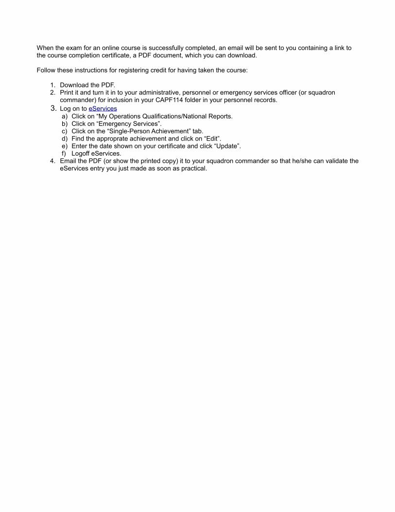
When the exam for an online course is successfully completed, an email will be sent to you containing a link to the course completion certificate, a PDF document, which you can download.
Follow these instructions for registering credit for having taken the course:
1. Download the PDF. 2. Print it and turn it in to your administrative, personnel or emergency services officer (or squadron
commander) for inclusion in your CAPF114 folder in your personnel records. 3. Log on to eServices
a) Click on “My Operations Qualifications/National Reports. b) Click on “Emergency Services”. c) Click on the “Single-Person Achievement” tab. d) Find the approprate achievement and click on “Edit”. e) Enter the date shown on your certificate and click “Update”. f) Logoff eServices.
4. Email the PDF (or show the printed copy) it to your squadron commander so that he/she can validate the eServices entry you just made as soon as practical.

O-2015 1-MAR-04
O-2015 DEMONSTRATE GROUND OPERATIONS AND SAFETY
CONDITIONS
You are a Mission Scanner trainee and must demonstrate safety around an aircraft on the ground.
OBJECTIVES
Demonstrate ramp safety, moving and loading aircraft, entry/egress, and basic fuel management.
TRAINING AND EVALUATION
Training Outline 1. As a Mission Scanner trainee, knowledge of aircraft ground operations and safety is essential. 2. Ramp safety:
a. Don't wear headgear, don't run, and always look out for moving aircraft and spinning propellers. b. No smoking within 50 feet of aircraft or fuel trucks/tanks. c. Keep clear of aircraft, especially the propeller or turbines. A propeller spins at over 2000 rpm, so you
may not be able to see it. If you see an aircraft sitting on the ramp with a rotating beacon or strobe light on, the pilot may be about to start the engine. Also, the trailing edges of the wings, flaps and ailerons may be sharp and are often at head level.
d. In case of a fire on the ground, get clear of the aircraft. Know where the nearest large fire extinguisher is. But, if fuel is spilling and it isn't necessary to help people clear of the fire, get away and call the fire department.
3. Moving aircraft. Never push or pull an aircraft without a pilot being present, and don't rotate, hold or move a propeller. Never push or stand on any part of the aircraft labeled "No Push." 4. Loading aircraft. Ensure all loose items are stowed and secured (e.g., under the cargo net). Loose objects can become projectiles during turbulence, hurting occupants or damaging equipment. Also, if you are about to load something that wasn't discussed prior to the flight (e.g., during the weight and balance calculations), tell the pilot. 5. Entry and egress:
a. Be careful where you step. Watch for "No Step" or "No Handhold" placards. b. As a rule, never enter or exit an aircraft while the engine is running. If you must, always ensure the
pilot knows your intentions and approach from the rear. c. Always wear your seatbelt and shoulder harness. Once above 1000 AGL you may remove your
shoulder harness, but it’s a good idea to keep it on unless performing an activity such as aerial imaging.
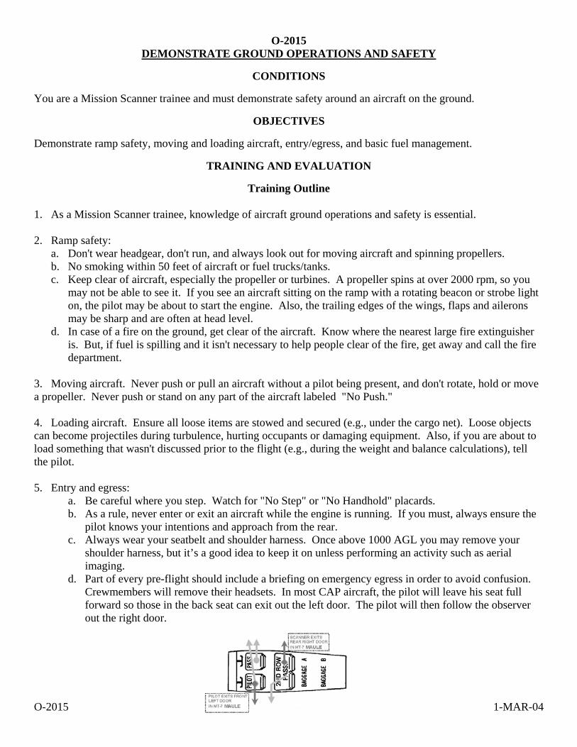
d. Part of every pre-flight should include a briefing on emergency egress in order to avoid confusion. Crewmembers will remove their headsets. In most CAP aircraft, the pilot will leave his seat full forward so those in the back seat can exit out the left door. The pilot will then follow the observer out the right door.
O-2015 1-MAR-04
6. Fuel management. The pilot is responsible for ensuring enough fuel is available to complete the flight safely with sufficient reserves left for diversions or emergencies. She should brief you on the fuel situation before the flight, including her assumptions on how much fuel will be needed (usually expressed in hours and minutes) and where you will refuel if necessary. Fuel status should be checked once an hour. Never feel hesitant to ask about your fuel status.
Additional Information
More detailed information on this topic is available in Chapter 2 of the MART.
Evaluation Preparation
Setup: The evaluation should be conducted with an aircraft on the ramp, with a PIC present.
Brief Student: You are a Scanner trainee asked about safety around aircraft on the ground.
Evaluation
Performance measures Results
1. Discuss ramp safety. P F
2. Demonstrate moving and loading an aircraft. P F
3. Demonstrate entry and emergency egress from all seats in the aircraft. P F
4. Discuss the scanner's role in basic fuel management. P F
Student must receive a pass on all performance measures to qualify in this task. If the individual fails any measure, show what was done wrong and how to do it correctly.
O-2017 1-MAR-04
O-2017 DISCUSS POST-CRASH ACTIONS
CONDITIONS
You are a Mission Scanner trainee and must discuss basic post-crash actions, and discuss survival equipment and urgent care.
OBJECTIVES
Discuss basic post-crash actions, identify and discuss survival equipment and urgent care.
TRAINING AND EVALUATION
Training Outline 1. As a Mission Scanner trainee, knowledge of basic survival techniques and urgent care is essential. 2. In the event of an off field landing, the crew will follow aircraft emergency procedures prior to the landing.
a. The pilot will review emergency egress procedures, the observer (right seat) will prop open the right door (headsets work nicely), and all crewmembers will tighten their seatbelts and shoulder harnesses. If the doors become jammed after the landing, kick them open or exit through the windows.
b. Afterwards, get clear of the aircraft if there is any danger (e.g., a fire). Check everyone for injuries and, as a precaution, sip some water to prevent shock.
3. Once the immediate danger is past, turn your attention to rescue. Hopefully the pilot or observer was able to communicate your position. In any case don't become impatient and leave the site, as your best chance of discovery is to stay near the aircraft. If rescue isn't expected shortly turn your attention to water, shelter and food (in that order). Remember, your will to survive is your greatest asset. 4. Survival. Water is your most important survival resource; always carry some with you plus a means to purify water (if water is available in the terrain you're flying over). Signaling equipment is also essential. For daytime use, nothing outperforms a signal mirror; at night a beacon or strobe works best. Handheld radios and personal ELTs are also very helpful. If you have no signaling device and you need to improvise, remember the "CLASS" acronym:
a. Color: make it an unnatural or highly contrasting one (not some color seen in your terrain). b. Location: put it where it can be seen most easily, usually high and in open areas. c. Angles: use angles not found in your terrain. d. Size: make it large, at least 12 feet in height. e. Shape: make it eye-catching.
5. Survival equipment. Know what is in your aircraft's survival kit. As a minimum it should include:
a. Water or a means of purifying water. b. Signal mirror and a strobe light. c. Space blankets for each crewmember. d. Rations (e.g., MREs). e. First aid kit and manual. f. Survival manual (matched to your terrain). g. Matches or fire starter. h. Compass. i. Knife.
O-2017 1-MAR-04
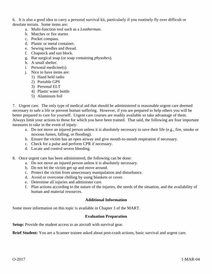
6. It is also a good idea to carry a personal survival kit, particularly if you routinely fly over difficult or desolate terrain. Some items are:
a. Multi-function tool such as a Leatherman. b. Matches or fire starter. c. Pocket compass. d. Plastic or metal container. e. Sewing needles and thread. f. Chapstick and sun block. g. Bar surgical soap (or soap containing physohex). h. A small shelter. i. Personal medicine(s). j. Nice to have items are:
1) Hand held radio 2) Portable GPS 3) Personal ELT 4) Plastic water bottle 5) Aluminum foil
7. Urgent care. The only type of medical aid that should be administered is reasonable urgent care deemed necessary to safe a life or prevent human suffering. However, if you are prepared to help others you will be better prepared to care for yourself. Urgent care courses are readily available so take advantage of them. Always limit your actions to those for which you have been trained. That said, the following are four important measures to take in the event of injury:
a. Do not move an injured person unless it is absolutely necessary to save their life (e.g., fire, smoke or noxious fumes, falling, or flooding).
b. Ensure the victim has an open airway and give mouth-to-mouth respiration if necessary. c. Check for a pulse and perform CPR if necessary. d. Locate and control severe bleeding.
8. Once urgent care has been administered, the following can be done:
a. Do not move an injured person unless it is absolutely necessary. b. Do not let the victim get up and move around. c. Protect the victim from unnecessary manipulation and disturbance. d. Avoid or overcome chilling by using blankets or cover. e. Determine all injuries and administer care. f. Plan actions according to the nature of the injuries, the needs of the situation, and the availability of
human and material resources.
Additional Information
Some more information on this topic is available in Chapter 3 of the MART.
Evaluation Preparation
Setup: Provide the student access to an aircraft with survival gear.
Brief Student: You are a Scanner trainee asked about post-crash actions, basic survival and urgent care.

O-2017 1-MAR-04
Evaluation
Performance measures Results
1. Discuss actions to take before and immediately after an off field landing. P F
2. Identify and discuss basic survival techniques and equipment. P F
3. Discuss basic urgent care, including four important measures for treating injuries. P F
Student must receive a pass on all performance measures to qualify in this task. If the individual fails any measure, show what was done wrong and how to do it correctly.

O-2019 1-MAR-04
O-2019 USE PROPER NUMBER AND CHARACTER PRONUNCIATION
CONDITIONS
You are a Mission Scanner trainee and must demonstrate proper pronunciation of numbers and characters when talking on the radios.
OBJECTIVES
Demonstrate proper pronunciation of numbers and characters when talking on the radios.
TRAINING AND EVALUATION
Training Outline 1. As a Mission Scanner trainee, knowledge of proper number and character pronunciation is essential for communicating on the radios. 2. Numbers. The table shows how to pronounce numbers over the radio:
Number Pronounced Number Pronounced
0 ZERO 9 NINE ER 1 WUN 10 WUN ZERO 2 TOO 11 WUN WUN 3 TREE 33 TREE TREE 4 FO WER 136 WUN TREE SIX 5 FI YIV 500 FI YIV HUN DRED 6 SIX 1478 WUN FO WER SEVEN ATE 7 SEVEN 2100 TOO WUN ZERO ZERO 8 ATE 128.1 WUN TOO EIGHT POINT ONE
3. Characters. The audio panel serves as the 'hub' of radio communications in the aircraft, and is normally set up by the pilot or observer. The scanner needs to know how to select the 'active' aircraft communications radio for transmission. The active radio is selected with the switch on the right-hand side of the panel. Select either COM 1 or COM 2 to transmit and receive on the frequency displayed in the associated radio's primary display.
Letter Word Pronunciation Letter Word Pronunciation A Alpha AL FAH N November NOE VEM BER B Bravo BRAH VOH O Oscar OSS CAH C Charlie CHAR LEE P Papa PAH PAH D Delta DELL TAH Q Quebec KEH BEK E Echo ECK OH R Romeo ROW ME OH F Foxtrot FOKS TROT S Sierra SEE AIR AH G Golf GOLF T Tango TANG GO H Hotel HOH TELL U Uniform YOU NEE FORM I India IN DEE AH V Victor VIK TAH J Juliet JEW LEE ETT W Whisky WISS KEY K Kilo KEY LO X X-Ray EKS RAY L Lima LEE MAH Y Yankee YANG KEE M Mike MIKE Z Zulu ZOO LOO
O-2019 1-MAR-04
Additional Information
More detailed information on this topic is available in Chapter 4 of the MART.
Evaluation Preparation
Setup: Provide the student access to a radio (may be simulated).
Brief Student: You are a Scanner trainee asked to correctly pronounce numbers and characters as you would when using a radio.
Evaluation
Performance measures Results
1. Demonstrate how to pronounce numbers while talking on a radio. P F
2. Demonstrate how to pronounce characters while talking on a radio. P F
Student must receive a pass on all performance measures to qualify in this task. If the individual fails any measure, show what was done wrong and how to do it correctly.
O-2020 17-MAR-04
O-2020 USE PROWORDS
CONDITIONS
You are a Mission Scanner trainee and must demonstrate proper use of prowords when talking on the radios.
OBJECTIVES
Properly use prowords when talking on the radios.
TRAINING AND EVALUATION
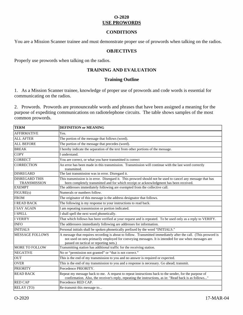
Training Outline 1. As a Mission Scanner trainee, knowledge of proper use of prowords and code words is essential for communicating on the radios. 2. Prowords. Prowords are pronounceable words and phrases that have been assigned a meaning for the purpose of expediting communications on radiotelephone circuits. The table shows samples of the most common prowords. TERM DEFINITION or MEANING AFFIRMATIVE Yes. ALL AFTER The portion of the message that follows (word). ALL BEFORE The portion of the message that precedes (word). BREAK I hereby indicate the separation of the text from other portions of the message. COPY I understand. CORRECT You are correct, or what you have transmitted is correct CORRECTION An error has been made in this transmission. Transmission will continue with the last word correctly
transmitted. DISREGARD The last transmission was in error. Disregard it. DISREGARD THIS
TRANSMISSION This transmission is in error. Disregard it. This proword should not be used to cancel any message that has
been completely transmitted and for which receipt or acknowledgment has been received. EXEMPT The addresses immediately following are exempted from the collective call. FIGURE(s) Numerals or numbers follow. FROM The originator of this message is the address designator that follows. I READ BACK The following is my response to your instructions to read back. I SAY AGAIN I am repeating transmission or portion indicated. I SPELL I shall spell the next word phonetically. I VERIFY That which follows has been verified at your request and is repeated. To be used only as a reply to VERIFY. INFO The addressees immediately following are addresses for information. INITIALS Personal initials shall be spoken phonetically prefixed by the word “INITIALS.” MESSAGE FOLLOWS A message that requires recording is about to follow. Transmitted immediately after the call. (This proword is
not used on nets primarily employed for conveying messages. It is intended for use when messages are passed on tactical or reporting nets.)
MORE TO FOLLOW Transmitting station has additional traffic for the receiving station. NEGATIVE No or “permission not granted” or “that is not correct.” OUT This is the end of my transmission to you and no answer is required or expected. OVER This is the end of my transmission to you and a response is necessary. Go ahead; transmit. PRIORITY Precedence PRIORITY. READ BACK Repeat my message back to me. A request to repeat instructions back to the sender, for the purpose of
confirmation. Also, the receiver's reply, repeating the instructions, as in: "Read back is as follows..." RED CAP Precedence RED CAP. RELAY (TO) Re-transmit this message to...
O-2020 17-MAR-04
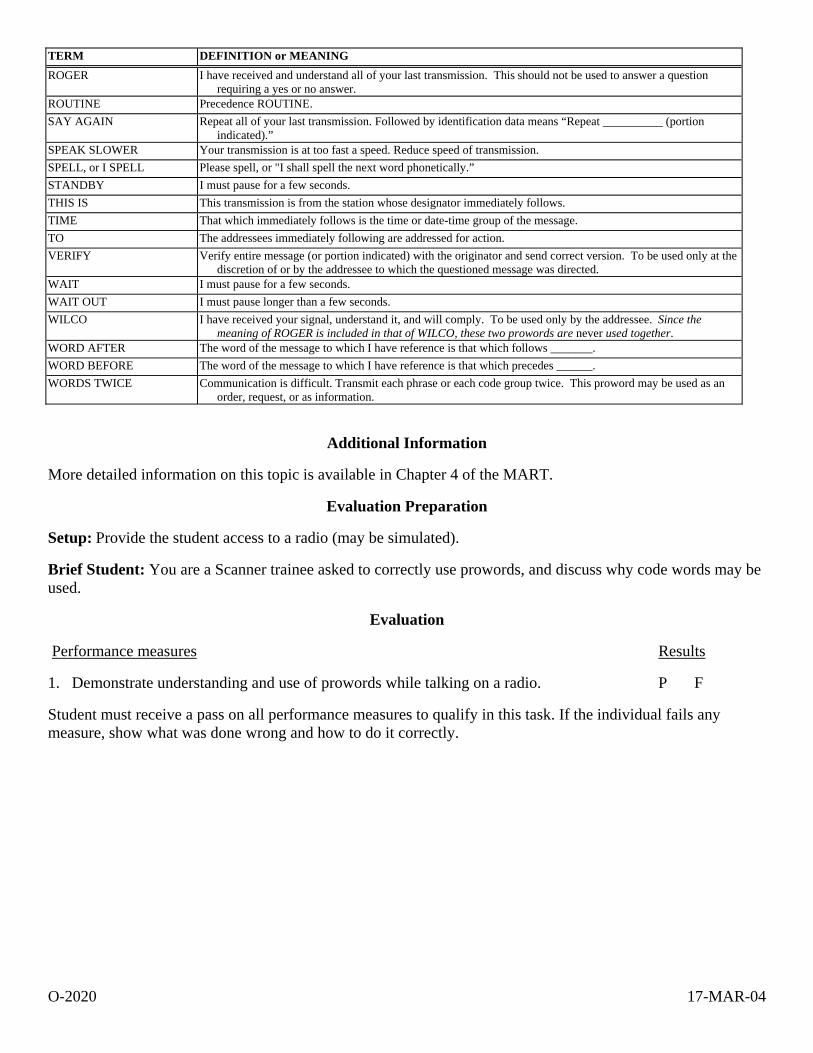
TERM DEFINITION or MEANING ROGER I have received and understand all of your last transmission. This should not be used to answer a question
requiring a yes or no answer. ROUTINE Precedence ROUTINE. SAY AGAIN Repeat all of your last transmission. Followed by identification data means “Repeat __________ (portion
indicated).” SPEAK SLOWER Your transmission is at too fast a speed. Reduce speed of transmission. SPELL, or I SPELL Please spell, or "I shall spell the next word phonetically.” STANDBY I must pause for a few seconds. THIS IS This transmission is from the station whose designator immediately follows. TIME That which immediately follows is the time or date-time group of the message. TO The addressees immediately following are addressed for action. VERIFY Verify entire message (or portion indicated) with the originator and send correct version. To be used only at the
discretion of or by the addressee to which the questioned message was directed. WAIT I must pause for a few seconds. WAIT OUT I must pause longer than a few seconds. WILCO I have received your signal, understand it, and will comply. To be used only by the addressee. Since the
meaning of ROGER is included in that of WILCO, these two prowords are never used together. WORD AFTER The word of the message to which I have reference is that which follows _______. WORD BEFORE The word of the message to which I have reference is that which precedes ______. WORDS TWICE Communication is difficult. Transmit each phrase or each code group twice. This proword may be used as an
order, request, or as information.
Additional Information
More detailed information on this topic is available in Chapter 4 of the MART.
Evaluation Preparation
Setup: Provide the student access to a radio (may be simulated).
Brief Student: You are a Scanner trainee asked to correctly use prowords, and discuss why code words may be used.
Evaluation
Performance measures Results
1. Demonstrate understanding and use of prowords while talking on a radio. P F
Student must receive a pass on all performance measures to qualify in this task. If the individual fails any measure, show what was done wrong and how to do it correctly.
O-2021 1-MAR-04
O-2021 INTREPRET EMERGENCY SIGNALS AND DEMONSTRATE
AIR/GROUND TEAM COORDINATION
CONDITIONS
You are a Mission Scanner trainee and must interpret emergency signals and demonstrate how to coordinate with ground teams.
OBJECTIVES
Interpret emergency signals and demonstrate and discuss air and ground team coordination plans and techniques.
TRAINING AND EVALUATION
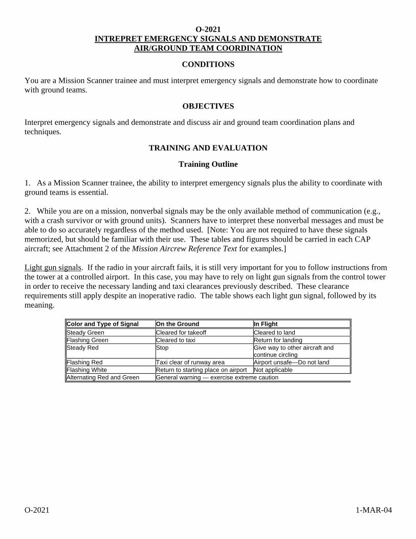
Training Outline 1. As a Mission Scanner trainee, the ability to interpret emergency signals plus the ability to coordinate with ground teams is essential. 2. While you are on a mission, nonverbal signals may be the only available method of communication (e.g., with a crash survivor or with ground units). Scanners have to interpret these nonverbal messages and must be able to do so accurately regardless of the method used. [Note: You are not required to have these signals memorized, but should be familiar with their use. These tables and figures should be carried in each CAP aircraft; see Attachment 2 of the Mission Aircrew Reference Text for examples.] Light gun signals. If the radio in your aircraft fails, it is still very important for you to follow instructions from the tower at a controlled airport. In this case, you may have to rely on light gun signals from the control tower in order to receive the necessary landing and taxi clearances previously described. These clearance requirements still apply despite an inoperative radio. The table shows each light gun signal, followed by its meaning.
Color and Type of Signal On the Ground In Flight Steady Green Cleared for takeoff Cleared to land Flashing Green Cleared to taxi Return for landing Steady Red Stop Give way to other aircraft and
continue circling Flashing Red Taxi clear of runway area Airport unsafe—Do not land Flashing White Return to starting place on airport Not applicable Alternating Red and Green General warning — exercise extreme caution

O-2021 1-MAR-04
Body signals. The use of the body is one of the most common means of sending messages. These signals are called "body signals" since they involve the whole body, not just arm movements. They are easy to use because no special materials are needed.
Wave Both arms across face Both arms held over head Cup hands over ears
DO NOT ATTEMPT TO LAND PICK UP - PLANE IS ABANDONED OUR RECEIVER IS WORKING
Lie flat on back with hands above head
NEED MEDICAL ASSISTANCE
Both arms horizontal Wave one arm over head Wave cloth horizontally
NEED MECHANIC HELP or PARTS ALL OK - DO NOT WAIT NEGATIVE – NO
Wave cloth vertically Both arms pointing in the direction One arm horizontal of landing while squatting
AFFIRMATIVE – YES LAND IN THIS DIRECTION WAIT IF PRACTICAL
O-2021 1-MAR-04
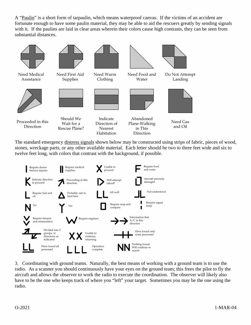
A “Paulin” is a short form of tarpaulin, which means waterproof canvas. If the victims of an accident are fortunate enough to have some paulin material, they may be able to aid the rescuers greatly by sending signals with it. If the paulins are laid in clear areas wherein their colors cause high contrasts, they can be seen from substantial distances.
Need MedicalAssistance
Need First AidSupplies
Need WarmClothing
Need Food andWater
Do Not AttemptLanding
Proceeded in thisDirection
Should WeWait for a
Rescue Plane?
IndicateDirection of
NearestHabitation
AbandonedPlane-Walking
in ThisDirection
Need Gasand Oil
The standard emergency distress signals shown below may be constructed using strips of fabric, pieces of wood, stones, wreckage parts, or any other available material. Each letter should be two to three feet wide and six to twelve feet long, with colors that contrast with the background, if possible.
Require doctorSerious injuries
Require medicalsupplies
Unable toproceed
Require foodand water
Indicate directionto proceed
Proceeding in thisdirection
Will attempttakeoff
Aircraft seriouslydamaged
Require fuel andoil
Probably safe toland here
All well Not understood
No Yes Require map andcompass
Require signallamp
Require firearmand ammunition
Require engineer Information thatA/C in thisdirection
Divided into 2groups, indirections asindicated
Unable tocontinue;returning
Have found onlysome personnel
Have found allpersonnel
Operationcomplete
Nothing found.Will continue tosearch
3. Coordinating with ground teams. Naturally, the best means of working with a ground team is to use the radio. As a scanner you should continuously have your eyes on the ground team; this frees the pilot to fly the aircraft and allows the observer to work the radio to execute the coordination. The observer will likely also have to be the one who keeps track of where you “left” your target. Sometimes you may be the one using the radio.
O-2021 1-MAR-04
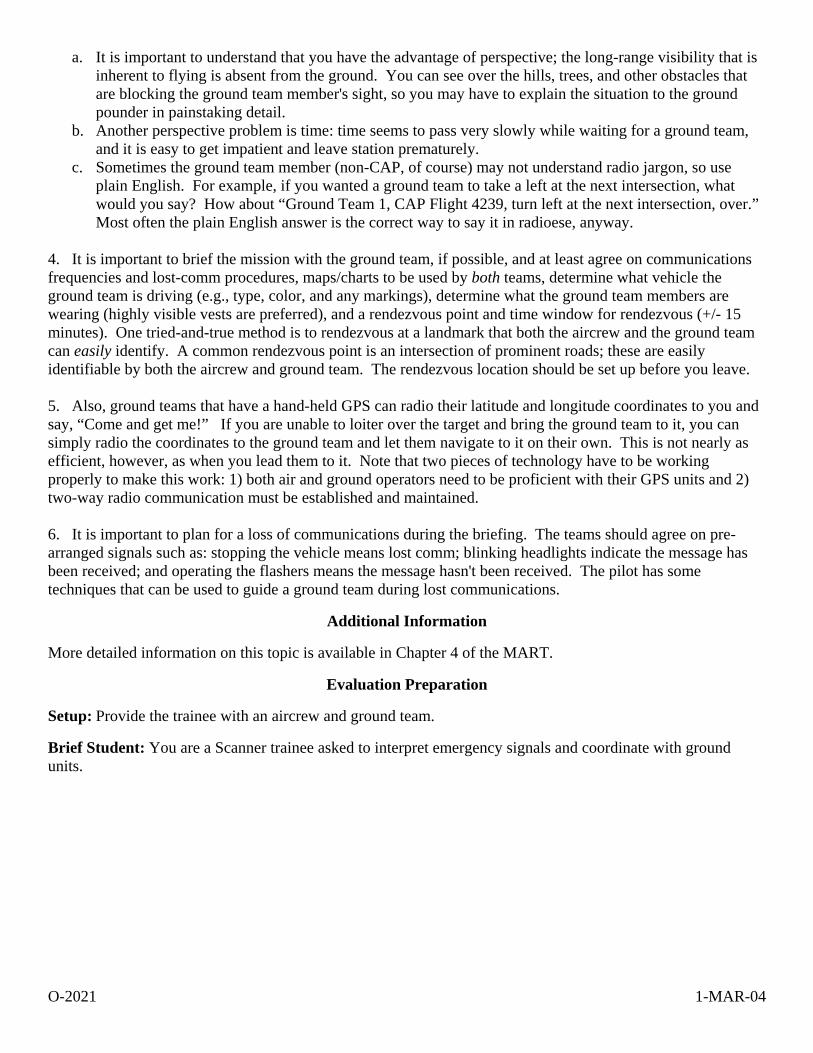
a. It is important to understand that you have the advantage of perspective; the long-range visibility that is inherent to flying is absent from the ground. You can see over the hills, trees, and other obstacles that are blocking the ground team member's sight, so you may have to explain the situation to the ground pounder in painstaking detail.
b. Another perspective problem is time: time seems to pass very slowly while waiting for a ground team, and it is easy to get impatient and leave station prematurely.
c. Sometimes the ground team member (non-CAP, of course) may not understand radio jargon, so use plain English. For example, if you wanted a ground team to take a left at the next intersection, what would you say? How about “Ground Team 1, CAP Flight 4239, turn left at the next intersection, over.” Most often the plain English answer is the correct way to say it in radioese, anyway.
4. It is important to brief the mission with the ground team, if possible, and at least agree on communications frequencies and lost-comm procedures, maps/charts to be used by both teams, determine what vehicle the ground team is driving (e.g., type, color, and any markings), determine what the ground team members are wearing (highly visible vests are preferred), and a rendezvous point and time window for rendezvous (+/- 15 minutes). One tried-and-true method is to rendezvous at a landmark that both the aircrew and the ground team can easily identify. A common rendezvous point is an intersection of prominent roads; these are easily identifiable by both the aircrew and ground team. The rendezvous location should be set up before you leave. 5. Also, ground teams that have a hand-held GPS can radio their latitude and longitude coordinates to you and say, “Come and get me!” If you are unable to loiter over the target and bring the ground team to it, you can simply radio the coordinates to the ground team and let them navigate to it on their own. This is not nearly as efficient, however, as when you lead them to it. Note that two pieces of technology have to be working properly to make this work: 1) both air and ground operators need to be proficient with their GPS units and 2) two-way radio communication must be established and maintained. 6. It is important to plan for a loss of communications during the briefing. The teams should agree on pre-arranged signals such as: stopping the vehicle means lost comm; blinking headlights indicate the message has been received; and operating the flashers means the message hasn't been received. The pilot has some techniques that can be used to guide a ground team during lost communications.
Additional Information
More detailed information on this topic is available in Chapter 4 of the MART.
Evaluation Preparation
Setup: Provide the trainee with an aircrew and ground team.
Brief Student: You are a Scanner trainee asked to interpret emergency signals and coordinate with ground units.
O-2021 1-MAR-04
Evaluation
Performance measures Results
1. Interpret the following emergency signals (may be performed on the ground):
a. Light gun signals P F
b. Body signals P F
c. Paulin signals P F
d. Distress signals P F
1. Discuss scanner responsibilities during a combined air/ground team mission. P F
2. Discuss factors to consider before you or the ground team leaves mission base. P F
3. Demonstrate basic ground team coordination. P F
Student must receive a pass on all performance measures to qualify in this task. If the individual fails any measure, show what was done wrong and how to do it correctly.

O-2024 1-MAR-04
O-2024 USE SECTIONAL CHARTS
CONDITIONS
You are a Mission Scanner trainee and must discuss the information displayed on a sectional chart and determine heading and distance
OBJECTIVES
Discuss the information displayed on a sectional chart and to determine heading and distance.
TRAINING AND EVALUATION
Training Outline 1. As a Mission Scanner trainee, basic knowledge the information contained on a sectional chart and its use is essential. The most important tool you will use in both mission flight planning and execution is the chart. Highway road maps are usually not acceptable for air navigation, since most don't have detailed terrain depiction and also lack the superimposed reference system. Many aeronautical charts have such small scales that the makers are unable to show required levels of detail when trying to put a large area into a small chart space. The most useful chart that has been widely accepted for visual, low-altitude navigation is the sectional aeronautical chart, sometimes simply referred to as the "sectional". 2. Sectional chart. Sectionals use a scale of one to five hundred thousand, or 1:500,000, where all features are shown 1/500,000 of their actual size (1 inch = 6.86 nm). This allows accurate depiction of both natural and cultural features without significant clutter. Sectionals portray the following:
a. Physical, natural features of the land, including terrain contours or lines of equal elevation. b. Man-made or cultural development, like cities, towns, towers, and racetracks. c. Visual and radio aids to navigation, airways, and special-use airspace. d. Airports and airport data, lines of magnetic variation, controlled airspace, obstructions and other
important information. e. VFR waypoints. f. Obstructions to flight.
3. Legend. An often overlooked but vital part of the sectional is the 'Legend.' This is a written explanation of symbols, projections, and other features used on the chart. Other important areas of the chart are its title page or "panel", and the margins around the chart edges. The margins contain supplemental radio frequency information, details about military or special use airspace, and other applicable regulations. The title panel identifies the region of the country shown by the chart, indicates the scale used in drawing the chart, explains elevations and contour shading, and shows the expiration date of the chart and effective date of the next issue of that chart. It is vitally important that you keep current charts in the aircraft at all times. 4. Interpretation. A significant part of air navigation involves interpreting what one sees on the chart, then making comparisons outside the aircraft. Basic chart symbols can be grouped into cultural features, drainage features, and relief features. Understanding cultural features is straightforward, and they usually require little explanation. Villages, towns, cities, railroads, highways, airports or landing strips, power transmission lines, towers, mines, and wells are all examples of cultural features. The chart legend explains the symbols used for most cultural features, but if no standard symbol exists for a feature of navigational significance, the cartographer frequently resorts to printing the name of the feature itself, such as factory or prison, on the chart.
O-2024 1-MAR-04
Drainage features on charts include lakes, streams, canals, swamps, and other bodies of water. On sectional charts these features are represented by lightweight solid blue lines for rivers and streams; large areas of water, such as lakes and reservoirs, are shaded light blue with the edges defined by lightweight solid blue lines. Under most conditions, the drainage features on a map closely resemble the actual bodies of water. However, certain bodies of water may change shape with the season, or after heavy rains or drought. Where this shape change occurs with predictability, cartographers frequently illustrate the maximum size expected for a body of water with light-weight, blue, dashed lines. If you intend to use drainage features for navigation, you should consider recent rains or dry spells while planning and remember the body of water may not appear exactly as depicted on the chart. Relief features indicate vertical topography of the land including mountains, valleys, hills, plains, and plateaus. Common methods of depicting relief features are contour lines, shading, color gradient tints, and spot elevations. Contour lines are the most common method of depicting vertical relief on charts. The lines do not represent topographical features themselves, but through careful study and interpretation, you can predict a feature's physical appearance without actually seeing it. Each contour line represents a continuous imaginary line on the ground on which all points have the same elevation above or below sea level, or the zero contours. Actual elevations above sea level of many contour lines are designated by a small break in the line, while others are not labeled. Contour interval, or vertical height between each line, is indicated on the title panel of sectionals. Contour lines are most useful in helping us to visualize vertical development of land features. Contour lines that are grouped very closely together indicate rapidly changing terrain, such as a cliff or mountain. More widely spaced lines indicate more gentle slopes. Absence of lines indicates flat terrain. Contour lines can also show changes in the slope of terrain. Shading is added to sectional charts to help highlight and give contrast to the contour lines. These tiny gray dots are applied adjacent to selected contour lines and give the contours a three-dimensional appearance. This makes it easier to imagine the physical appearance of the shaded topographical feature. Gradient tints, the "background" colors on charts, indicate general areas of elevation. The height range assigned to each gradient color is indicated on the title panel of each sectional chart. Areas that are near sea level are pale green, while high terrain is color-coded a deep red/brown. Intermediate elevations are indicated by brighter shades of green, tan, or lighter shades of red/brown. 5. Aeronautical data. The aeronautical information on the sectional charts is for the most part self-explanatory. An explanation for most symbols used on aeronautical charts appears in the margin of the chart. Additional information appears at the bottom of the chart. Information concerning very high frequency (VHF) radio facilities such as tower frequencies, omnidirectional radio ranges (VOR), and other VHF communications frequencies is shown in blue. A narrow band of blue tint is also used to indicate the centerlines of Victor Airways (VOR civil airways between omnirange stations). Low frequency-medium frequency (LF/MF) radio facilities are shown in magenta (purplish shade of red). Runway patterns are shown for all airports having permanent hard surfaced runways. These patterns provide for positive identification as landmarks. All recognizable runways, including those that may be closed, are shown to aid in visual identification. Airports and information pertaining to airports having an airport traffic area (operating control tower) are shown in blue. All other airports and information pertaining to these airports are shown in magenta adjacent to the airport symbol that is also in magenta. The symbol for obstructions is another important feature. The elevation of the top of obstructions above sea level is given in blue figures (without parentheses) adjacent to the obstruction symbol. Immediately below this set of figures is another set of lighter blue figures (enclosed in parentheses) that represent the height of the top of the obstruction above ground-level. Obstructions which extend less than 1,000 feet above the terrain are
O-2024 1-MAR-04
shown by one type of symbol and those obstructions that extend 1,000 feet or higher above ground level are indicated by a different symbol (see sectional chart). Specific elevations of certain high points in terrain are shown on charts by dots accompanied by small black figures indicating the number of feet above sea level. The chart also contains larger bold face blue numbers that denote Maximum Elevation Figures (MEF). These figures are shown in quadrangles bounded by ticked lines of latitude and longitude, and are represented in thousands and hundreds of feet above mean sea level. The MEF is based on information available concerning the highest known feature in each quadrangle, including terrain and obstructions (e.g., trees, towers, and antennas). Since CAP aircraft regularly fly at or below 1000' AGL, aircrews should exercise extreme caution because of the numerous structures extending up as high as 1000' – 2000' AGL. Additionally, guy wires that are difficult to see even in clear weather support most truss-type structures; these wires can extend approximately 1500 feet horizontally from a structure. Therefore, all truss-type structures should be avoided by at least 2000 feet (horizontally and vertically). 6. Determining heading and distance. To determine a heading, locate the departure and destination points on the chart and lay the edge of a special protractor, or plotter, along a line connecting the two points. Read the true course for this leg by sliding the plotter left or right until the center point, or grommet, sits on top of a line of longitude. When the course is more to the north or south, you can measure it by centering the grommet on a parallel of latitude, then reading the course from the inner scale that’s closer to the grommet. To determine distance, use the scale that's printed on the plotter's straight edge: one edge measures nautical miles and the other statute miles. 7. Grids. CAP has adopted a standard grid system built upon the matrix of parallels of latitude and meridians of longitude and the sectional aeronautical chart. Sectional charts cover a land area approximately seven degrees of longitude in width and four degrees of latitude in height. Information pertaining to gridding can be found in Attachment E of the U.S. National SAR Supplement to the International Aeronautical and Maritime SAR Manual (or Attachment 1 of the MART). The sectional grid system used by Civil Air Patrol divides each sectional’s area into 448 smaller squares. This process begins by dividing the whole area into 28 1-degree grids, using whole degrees of latitude and longitude. Then each 1-degree grid is divided into four 30-minute grids, using the 30-minute latitude and longitude lines. Finally, each of the 30-minute grids is divided into four 15-minute grids, using the 15- and 45-minute latitude and longitude lines. When circumstances require, a 15-minute grid can be divided into four more quadrants using 7 1/2 degree increments of latitude and longitude, creating four equal size grids that are approximately 7 1/2 miles square. The quadrants are then identified alphabetically - A through D - starting with the northwest quadrant as A, northeast as B, southwest as C and southeast as D. [If needed, a 7 1/2 degree grid can be further subdivided into four quadrants using the same methodology: using the 7 1/2 degree grid 'A', the quadrants would be labeled AA, AB, AC and AD.] Another means of designating a grid system is the Standardized Latitude and Longitude Grid System. It has an advantage over the sectional standardized grid in that it can be used on any kind of chart that has lines of latitude and longitude already marked. In this system, 1-degree blocks are identified by the intersection of whole numbers of latitude and longitude, such as 36-00N and 102-00W: these points are always designated with the latitude first, such as 36/102, and they identify the area north and west of the intersection of these two lines. Next, the 1-degree grid is divided into four quadrants using the 30-minute lines of latitude and longitude. Label each quadrant A through D; the northwest quadrant being 36/102A, the northeast 36/102B, the southwest 36/102C, and the southeast 36/102D. Each quadrant can also be divided into four sub-quadrants, labeled AA, AB, AC, and AD, again starting with the most northwest and proceeding clockwise.
O-2024 1-MAR-04
Additional Information
More detailed information and pictures on this topic are available in Chapter 8 of the MART.
Evaluation Preparation
Setup: Provide the student with a sectional chart and a plotter.
Brief Student: You are a Scanner trainee asked to discuss the information displayed on a sectional chart, and to determine heading and distance.
Evaluation
Performance measures Results
1. Identify and discuss the following on an aeronautical sectional chart:
a. Physical features such as topographical details.
b. Towns, cities, highways, roads, and towers (MSL and AGL).
c. Airways, radio aids, airports and airport data.
d. Maximum Elevation Figures.
e. Legend and margin information. P F
2. Given a sectional and plotter, determine a heading and measure distances. P F
3. State the size of a full and one-quarter CAP and Standardized grids. P F
Student must receive a pass on all performance measures to qualify in this task. If the individual fails any measure, show what was done wrong and how to do it correctly.

P-2013 1-MAR-04
P-2013 DISCUSS MISSION SCANNER DUTIES AND RESPONSIBILITIES
CONDITIONS
You are a Mission Scanner trainee and must discuss scanner duties and responsibilities.
OBJECTIVES
Discuss scanner duties and responsibilities.
TRAINING AND EVALUATION
Training Outline 1. As a Mission Scanner trainee, understanding your duties and responsibilities is essential. Additionally, a basic knowledge of the Mission Observer's duties and responsibilities is helpful. 2. The scanner's primary role is performing an effective visual search, maintaining constant eye contact with the ground while flying over the search area. 3. A scanner must report to duty in accordance with the "IM SAFE" criteria of CAPR 60-1. This covers illness, medication, stress, alcohol, fatigue, and emotion. 4. Other duties and responsibilities include: a. Wear appropriate clothes for a mission. b. Carry and properly use equipment. Return borrowed or assigned equipment. c. Carry current credentials. d. Assist in avoiding obstacles during taxiing. e. Obey sterile cockpit rules. f. Report observations accurately and honestly, and report all sightings. g. Keep accurate sketches and notes. h. Properly complete all pertinent paperwork. i. Report availability for additional assignments. 5. Review and discuss observer duties and responsibilities: a. Report with the mission pilot for briefings. b. Assist in planning the mission. c. Assist in avoiding collisions and obstacles during taxiing. d. Assist in setting up and operating aircraft and CAP radios. e. Assist in setting up and operating aircraft navigational equipment. f. Assist enforcing sterile cockpit rules. g. Maintain situational awareness at all times. h. Assist in monitoring fuel status.
i. Monitor the electronic search devices aboard the aircraft and advise the pilot when making course corrections in response to ELT signals.
j. Keep mission base and/or high bird appraised of status. k. Coordinate scanner assignments and ensure proper breaks for the scanners; monitor the crew for fatigue
and dehydration.
P-2013 1-MAR-04
l. Maintain a chronological flight log of all observations of note, including precise locations, sketches and any other noteworthy information.
m. Report with the mission pilot for debriefing; assist in completing the reverse of CAPF 104. n. Keep track of assigned supplies and equipment.
Additional Information
More detailed information on this topic is available in CAPR 60-1 and in Chapter 1 of the Mission Aircrew Reference Text (MART).
Evaluation Preparation
Setup: Provide the student with a current copy of CAPR 60-1 and the MART.
Brief Student: You are a Scanner trainee asked about your duties and responsibilities, and to discuss the Scanner's job.
Evaluation
Performance measures Results
1. State the primary role of the scanner. P F
2. Discuss the "IM SAFE" criteria. P F
3. Discuss other scanner duties and responsibilities. P F
4. Review the observer duties and responsibilities. P F
Student must receive a pass on all performance measures to qualify in this task. If the individual fails any measure, show what was done wrong and how to do it correctly.

P-2014 1-MAR-04
P-2014 DISCUSS CAP LIABILITY COVERAGE AND MISHAP REPORTING
CONDITIONS
You are a Mission Scanner trainee and must discuss CAP liability coverage and mishap reporting.
OBJECTIVES
Discuss liability coverage provided to CAP personnel and mishap reporting.
TRAINING AND EVALUATION
Training Outline 1. As a mission aircrew member there is a small chance that you may be involved in an accident during a mission. A basic knowledge of liability coverage provided to you, and its applicability and limitations, is essential. 2. Using the current CAPR 900-5 discuss the following, including when the coverage applies and what is covered: a. Federal Employee Compensation Act (FECA). b. Federal Tort Claims Act (FTCA). c. CAP corporate insurance. 3. Using the current CAPR 62-2 and CAPF 78 (Mishap Report Form), discuss what constitutes an accident, when it must be reported, what information is needed, and who it is given to. 4. Using the current CAPR 60-1, discuss assessments that can be made for damage to CAP aircraft.
Additional Information
More detailed information on this topic is available in Chapter 1 of the Mission Aircrew Reference Text (MART).
Evaluation Preparation
Setup: Provide the student with current copies of CAPR 900-5, 62-2 (with a copy of CAPF 78), and 60-1.
Brief Student: You are an aircrew member asked to discuss FECA, FTCA and CAP corporate coverage, reporting requirements in case of an accident, and assessments that may be made for aircraft damage.
Evaluation
Performance measures Results
1. Discuss FECA, including what types of missions afford this coverage and what is covered. P F
2. Discuss FTCA, including what types of missions afford this coverage and what is covered. P F
3. Discuss the various assessments that can be made for damage to CAP aircraft. P F

P-2014 1-MAR-04
3. Discuss CAP corporate insurance, including what types of missions afford this coverage and what is covered. P F
4. Discuss CAP mishap reporting, including what must be reported, how, and to whom. P F
Student must receive a pass on all performance measures to qualify in this task. If the individual fails any measure, show what was done wrong and how to do it correctly.

P-2015 1-MAR-04
P-2015 ENTER DATA INTO CAP FORMS
CONDITIONS
You are a Mission Scanner trainee and must enter data into a form.
OBJECTIVES
Accurately and legibly enter data into forms and show how to correct mistakes.
TRAINING AND EVALUATION
Training Outline 1. As a Mission Scanner trainee you must know how to enter data into forms and how to correct mistakes. 2. CAP and our partner agencies rely on accurate and complete paperwork. CAP strives to maintain a professional image, and providing data that is legible is essential to this image. 3. Filling out forms and other paperwork is an essential part of any mission. Time and effort must be given to this part of the mission. 4. Some general rules to follow:
a. It is important not to obliterate a mistake (i.e., a person should still be able to read the mistaken entry). To correct mistakes, draw a single line through the error, enter the correct data, and initial.
b. Do not use of "liquid paper" when making corrections. c. Do not use signature labels or stamped signatures.
d. Attachments (e.g., maps or sketches) should have your name, the date, aircraft 'N' number, mission and sortie numbers, and Hobbs time on them so they can be tied to the CAP form if they become separated.
e. Do not leave blanks; enter N/A in the blank. f. Always have another crewmember review the form before submittal.
Additional Information
More detailed information on this topic is available in Chapter 1 of the MART.
Evaluation Preparation
Setup: Provide the student with a current copy of CAPF 104.
Brief Student: You are a Scanner trainee asked general rules for entering data into forms, marking attachments to forms, and correcting mistakes.
Evaluation
Performance measures Results
1. Show how to correct a mistake. P F
2. Show how to mark a map that you will attach to a form. P F
Student must receive a pass on all performance measures to qualify in this task. If the individual fails any measure, show what was done wrong and how to do it correctly.
P-2016 1-MAR-04
P-2016 IDENTIFY AND DISCUSS MAJOR AIRCRAFT CONTROLS
CONDITIONS
You are a Mission Scanner trainee and must identify and describe the major aircraft control features.
OBJECTIVES
Identify and discuss major aircraft controls.
TRAINING AND EVALUATION
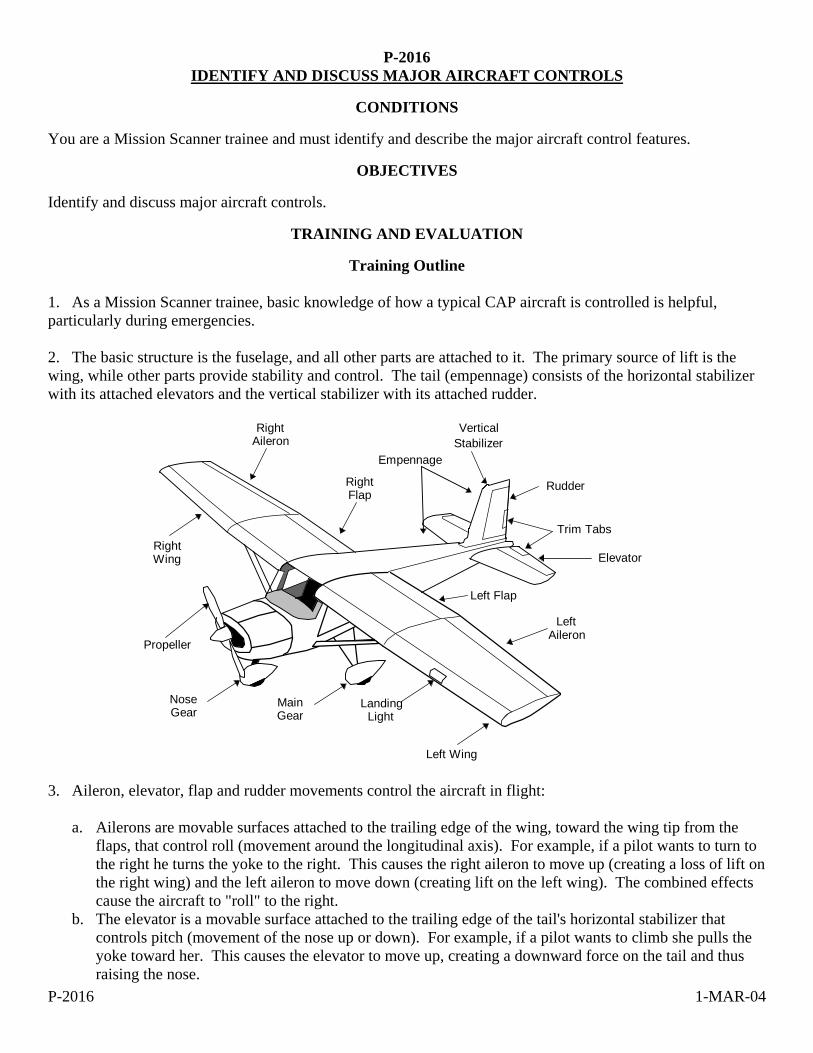
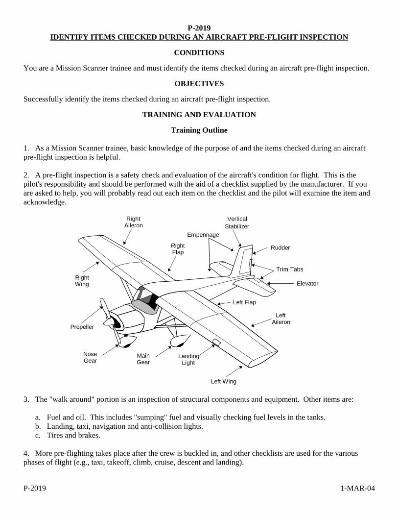
Training Outline 1. As a Mission Scanner trainee, basic knowledge of how a typical CAP aircraft is controlled is helpful, particularly during emergencies. 2. The basic structure is the fuselage, and all other parts are attached to it. The primary source of lift is the wing, while other parts provide stability and control. The tail (empennage) consists of the horizontal stabilizer with its attached elevators and the vertical stabilizer with its attached rudder.
RightAileron
RightFlap
RightWing
NoseGear
Propeller
MainGear
Left Wing
LandingLight
LeftAileron
Left Flap
Elevator
Trim Tabs
Rudder
VerticalStabilizer
Empennage
3. Aileron, elevator, flap and rudder movements control the aircraft in flight:
a. Ailerons are movable surfaces attached to the trailing edge of the wing, toward the wing tip from the flaps, that control roll (movement around the longitudinal axis). For example, if a pilot wants to turn to the right he turns the yoke to the right. This causes the right aileron to move up (creating a loss of lift on the right wing) and the left aileron to move down (creating lift on the left wing). The combined effects cause the aircraft to "roll" to the right.
b. The elevator is a movable surface attached to the trailing edge of the tail's horizontal stabilizer that controls pitch (movement of the nose up or down). For example, if a pilot wants to climb she pulls the yoke toward her. This causes the elevator to move up, creating a downward force on the tail and thus raising the nose.
P-2016 1-MAR-04
c. The flaps are electrically driven movable surfaces attached to the trailing edge of the wing, inboard of the ailerons. Deflection of the flaps (to a certain point) significantly increases lift. The pilot uses them during takeoff and landing.
d. Rudders are movable surfaces attached to the trailing edge of the tail's vertical stabilizer that control yaw (side-to-side movement around the vertical axis). For example, if a pilot pushes the left rudder pedal the rudder swings to the left, creating a force that pushes the tail in the opposite direction (i.e., to the right). The nose of the aircraft then moves (yaws) to the left. [Note: the rudder pedals also move the aircraft nose wheel. When taxiing, to steer to the left the pilot would depress the left rudder pedal.]
e. Although not a control surface, the throttle is a push rod with a black knob, located on the panel, that controls aircraft engine power. Pushing the knob in (towards the panel) increases power and pulling it out (towards you) decreases power.
Additional Information
More detailed information on this topic is available in Chapter 2 of the MART.
Evaluation Preparation
Setup: Provide the student access to an aircraft (or picture or model that shows aircraft control surfaces).
Brief Student: You are a Scanner trainee asked to identify and discuss the major aircraft control surfaces.
Evaluation
Performance measures Results
1. Demonstrate and discuss how the pilot turns (rolls) the aircraft left or right. P F
2. Demonstrate and discuss how the pilot makes the aircraft climb or dive. P F
3. Demonstrate and discuss how the pilot moves the aircraft's nose to the left or right. P F
4. Demonstrate and discuss how the pilot steers the aircraft to the left or right while taxiing. P F
5. Demonstrate and discuss how the pilot increases or decreases engine power. P F
Student must receive a pass on all performance measures to qualify in this task. If the individual fails any measure, show what was done wrong and how to do it correctly.
P-2017 17-MAR-04
P-2017 IDENTIFY AND DISCUSS MAJOR AIRCRAFT INSTRUMENTS
CONDITIONS
You are a Mission Scanner trainee and must identify and discuss major aircraft instruments.
OBJECTIVES
Identify and discuss major aircraft instruments.
TRAINING AND EVALUATION
Training Outline 1. As a Mission Scanner trainee, basic knowledge of typical CAP aircraft instruments is helpful, particularly during an emergency. 2. Refer to MART Chapter 2 for pictures of the following instruments. The basic instruments are:
a. The magnetic compass shows the aircraft's heading in relationship to earth's magnetic North Pole. b. The heading indicator is set to the magnetic compass. A gyroscope, it provides a steady reading that is
easier for the pilot to read than the magnetic compass. c. The altimeter shows altitude above mean sea level. d. The airspeed indicator shows the speed at which the aircraft is moving through the air. e. The attitude indicator (artificial horizon) is highly reliable and provides a very realistic picture of the
attitude of the aircraft (turning, climbing or diving). f. Other engine instruments provide fuel level and engine performance. g. The global positioning system (GPS) is a satellite-based system that provides highly accurate position
and velocity information (altitude, heading and speed). i. The nav/comm (navigation/communications) radios allow the pilot or observer to communicate with air
traffic control and other agencies. j. The audio panel acts as the communications 'hub' of the aircraft. It allows the pilot or observer to select
which radio is active, and directs other communication and navigation instruments to the crew headsets or the overhead speaker.
k. The transponder provides a signal to air traffic control that lets them know the aircraft's identification, position and altitude.
3. Do not reposition any aircraft instrument's settings or controls without first asking the pilot.
Additional Information
More detailed information on this topic is available in Chapter 2 of the MART.
Evaluation Preparation
Setup: Provide the student access to an aircraft (or a picture or model that shows aircraft instruments).
Brief Student: You are a Scanner trainee asked the basics about aircraft instruments.

P-2017 17-MAR-04
Evaluation
Performance measures Results
1. Identify and describe the basic function of the following aircraft instruments: a. Magnetic compass P F
b. Heading indicator P F
c. Altimeter P F
d. Airspeed indicator P F
e. Attitude indicator P F
f. GPS P F
g. Radios P F
h. Audio panel P F
i. Transponder P F
2. State the rule on repositioning any aircraft instrument's settings or controls. P F
Student must receive a pass on all performance measures to qualify in this task. If the individual fails any measure, show what was done wrong and how to do it correctly.
P-2018 1-MAR-04
P-2018 DISCUSS AIRCRAFT WEIGHT AND BALANCE
CONDITIONS
You are a Mission Scanner trainee and must discuss aircraft weight and balance.
OBJECTIVES
Discuss aircraft weight and balance criteria and describe the potential consequences of exceeding gross weight limits, and being "tail heavy" or "nose heavy."
TRAINING AND EVALUATION
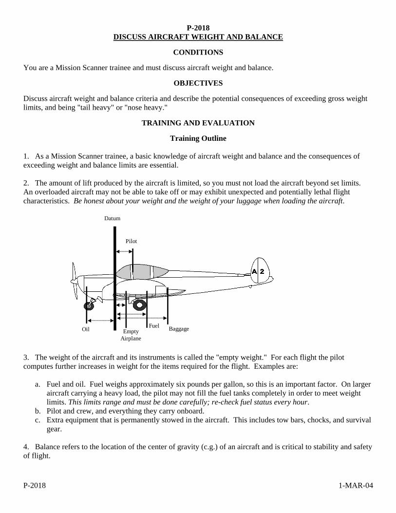
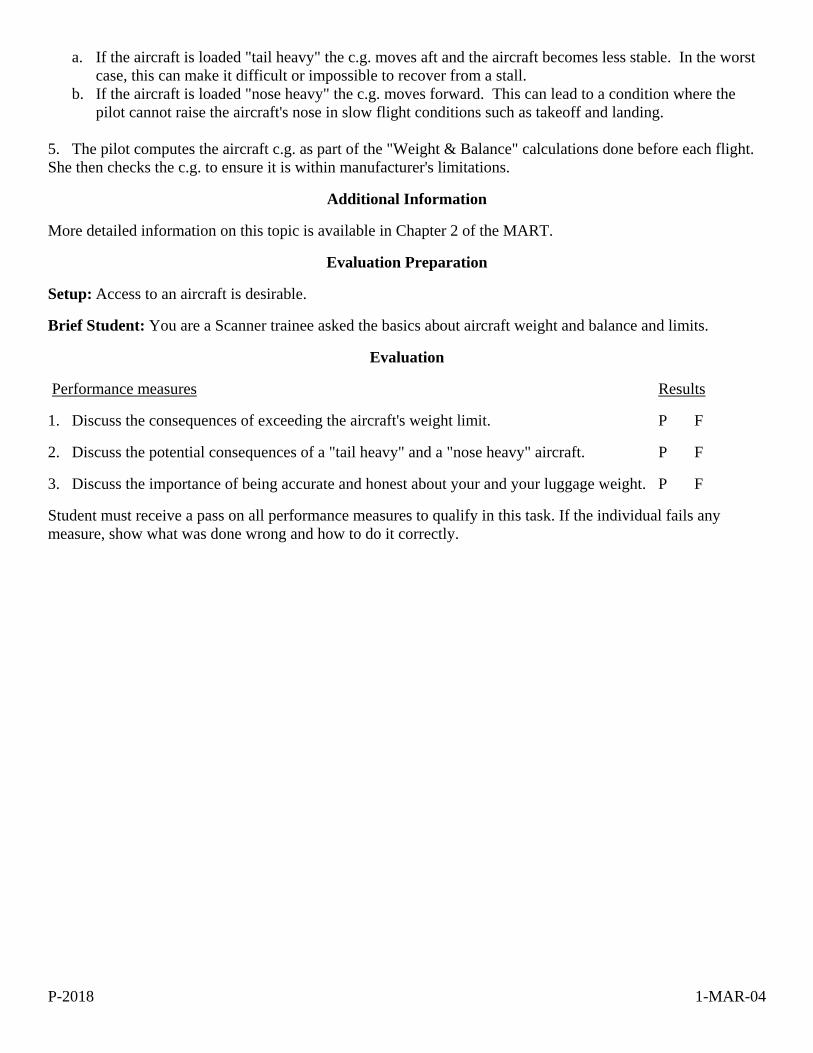
Training Outline 1. As a Mission Scanner trainee, a basic knowledge of aircraft weight and balance and the consequences of exceeding weight and balance limits are essential. 2. The amount of lift produced by the aircraft is limited, so you must not load the aircraft beyond set limits. An overloaded aircraft may not be able to take off or may exhibit unexpected and potentially lethal flight characteristics. Be honest about your weight and the weight of your luggage when loading the aircraft.
Datum
Pilot
Fuel BaggageOil Empty Airplane
3. The weight of the aircraft and its instruments is called the "empty weight." For each flight the pilot computes further increases in weight for the items required for the flight. Examples are:
a. Fuel and oil. Fuel weighs approximately six pounds per gallon, so this is an important factor. On larger aircraft carrying a heavy load, the pilot may not fill the fuel tanks completely in order to meet weight limits. This limits range and must be done carefully; re-check fuel status every hour.
b. Pilot and crew, and everything they carry onboard. c. Extra equipment that is permanently stowed in the aircraft. This includes tow bars, chocks, and survival
gear. 4. Balance refers to the location of the center of gravity (c.g.) of an aircraft and is critical to stability and safety of flight.
P-2018 1-MAR-04
a. If the aircraft is loaded "tail heavy" the c.g. moves aft and the aircraft becomes less stable. In the worst case, this can make it difficult or impossible to recover from a stall.
b. If the aircraft is loaded "nose heavy" the c.g. moves forward. This can lead to a condition where the pilot cannot raise the aircraft's nose in slow flight conditions such as takeoff and landing.
5. The pilot computes the aircraft c.g. as part of the "Weight & Balance" calculations done before each flight. She then checks the c.g. to ensure it is within manufacturer's limitations.
Additional Information
More detailed information on this topic is available in Chapter 2 of the MART.
Evaluation Preparation
Setup: Access to an aircraft is desirable.
Brief Student: You are a Scanner trainee asked the basics about aircraft weight and balance and limits.
Evaluation
Performance measures Results
1. Discuss the consequences of exceeding the aircraft's weight limit. P F
2. Discuss the potential consequences of a "tail heavy" and a "nose heavy" aircraft. P F
3. Discuss the importance of being accurate and honest about your and your luggage weight. P F
Student must receive a pass on all performance measures to qualify in this task. If the individual fails any measure, show what was done wrong and how to do it correctly.
P-2019 1-MAR-04
P-2019 IDENTIFY ITEMS CHECKED DURING AN AIRCRAFT PRE-FLIGHT INSPECTION
CONDITIONS
You are a Mission Scanner trainee and must identify the items checked during an aircraft pre-flight inspection.
OBJECTIVES
Successfully identify the items checked during an aircraft pre-flight inspection.
TRAINING AND EVALUATION
Training Outline 1. As a Mission Scanner trainee, basic knowledge of the purpose of and the items checked during an aircraft pre-flight inspection is helpful. 2. A pre-flight inspection is a safety check and evaluation of the aircraft's condition for flight. This is the pilot's responsibility and should be performed with the aid of a checklist supplied by the manufacturer. If you are asked to help, you will probably read out each item on the checklist and the pilot will examine the item and acknowledge.
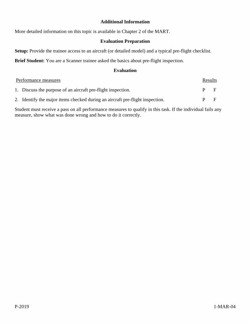
RightAileron
RightFlap
RightWing
NoseGear
Propeller
MainGear
Left Wing
LandingLight
LeftAileron
Left Flap
Elevator
Trim Tabs
Rudder
VerticalStabilizer
Empennage
3. The "walk around" portion is an inspection of structural components and equipment. Other items are:
a. Fuel and oil. This includes "sumping" fuel and visually checking fuel levels in the tanks. b. Landing, taxi, navigation and anti-collision lights. c. Tires and brakes.
4. More pre-flighting takes place after the crew is buckled in, and other checklists are used for the various phases of flight (e.g., taxi, takeoff, climb, cruise, descent and landing).
P-2019 1-MAR-04
Additional Information
More detailed information on this topic is available in Chapter 2 of the MART.
Evaluation Preparation
Setup: Provide the trainee access to an aircraft (or detailed model) and a typical pre-flight checklist.
Brief Student: You are a Scanner trainee asked the basics about pre-flight inspection.
Evaluation
Performance measures Results
1. Discuss the purpose of an aircraft pre-flight inspection. P F
2. Identify the major items checked during an aircraft pre-flight inspection. P F
Student must receive a pass on all performance measures to qualify in this task. If the individual fails any measure, show what was done wrong and how to do it correctly.
P-2020 1-MAR-04
P-2020 DISCUSS THE DANGERS OF WAKE TURBULENCE
CONDITIONS
You are a Mission Scanner trainee and must discuss the dangers of wake turbulence.
OBJECTIVES
Discuss wake turbulence, including where it is most likely to be encountered.
TRAINING AND EVALUATION
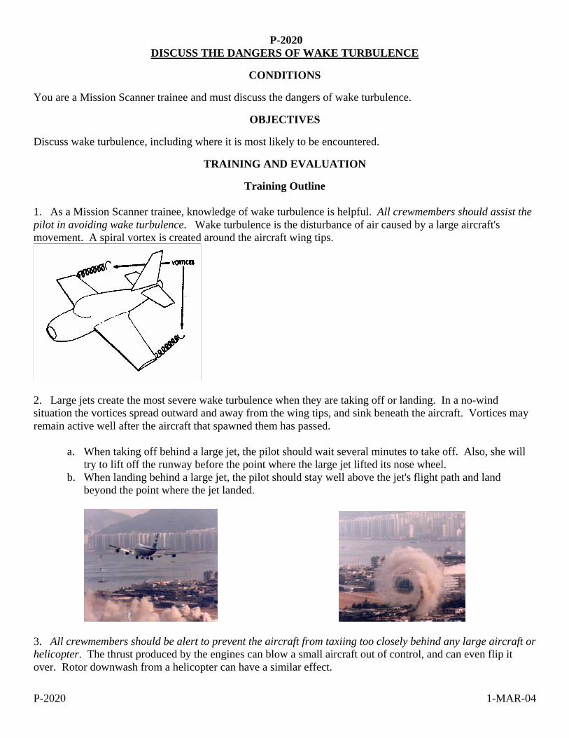
Training Outline 1. As a Mission Scanner trainee, knowledge of wake turbulence is helpful. All crewmembers should assist the pilot in avoiding wake turbulence. Wake turbulence is the disturbance of air caused by a large aircraft's movement. A spiral vortex is created around the aircraft wing tips.
2. Large jets create the most severe wake turbulence when they are taking off or landing. In a no-wind situation the vortices spread outward and away from the wing tips, and sink beneath the aircraft. Vortices may remain active well after the aircraft that spawned them has passed.
a. When taking off behind a large jet, the pilot should wait several minutes to take off. Also, she will try to lift off the runway before the point where the large jet lifted its nose wheel.
b. When landing behind a large jet, the pilot should stay well above the jet's flight path and land beyond the point where the jet landed.
3. All crewmembers should be alert to prevent the aircraft from taxiing too closely behind any large aircraft or helicopter. The thrust produced by the engines can blow a small aircraft out of control, and can even flip it over. Rotor downwash from a helicopter can have a similar effect.
P-2020 1-MAR-04
Additional Information
More detailed information on this topic is available in Chapter 2 of the MART.
Evaluation Preparation
Setup: Paper for drawings.
Brief Student: You are a Scanner trainee asked about wake turbulence.
Evaluation
Performance measures Results
1. Discuss where wake turbulence is normally encountered. P F
2. Discuss basic takeoff and landing precautions taken to avoid wake turbulence. P F
3. Discuss the dangers of taxiing to close behind large jets or helicopters. P F
Student must receive a pass on all performance measures to qualify in this task. If the individual fails any measure, show what was done wrong and how to do it correctly.

P-2021 1-MAR-04
P-2021 DISCUSS HOW ATMOSPHERIC AND LIGHTING CONDITIONS EFFECT SCANNING
EFFECTIVENESS
CONDITIONS
You are a Mission Scanner trainee and must discuss how atmospheric and lighting conditions effect scanning effectiveness.
OBJECTIVES
Discuss how atmospheric and lighting conditions effect scanning effectiveness.
TRAINING AND EVALUATION
Training Outline 1. As a Mission Scanner trainee, knowing how atmospheric and lighting conditions effect scanning is essential.
During daylight there are many factors that can affect the scanner's ability to spot the search target. The following table shows the (approximate) distance at which the scanner can sight various objects under average visibility conditions; factors that can alter these distances are discussed below.
Object Distance
Person in life jacket (open water or moderate seas) 1/2 mile Person in small life raft (open water or moderate seas) 3/4 mile Person in open meadow within wooded area 1/2 mile or less Crash in wooded area 1/2 mile Crash on desert or open plain 2 miles Person on desert or open plain 1 mile or less Vehicle in open area 2 miles or less
During darkness, scanners make fewer fixations in their search patterns than during daylight because victims in distress are likely to use lights, fires, or flares to signal rescuers. Contrast between signal light and surrounding darkness eliminates the need for scanners to concentrate on making numerous eye fixations. An attentive scanner or observer should be able to see a light, flare, or fire easily during night operations. Search aircraft interior lighting should be kept to the lowest possible level that still allows normal chart reading. This will help the eyes adjust to the darkness and reduce glare on windshield and window surfaces. Red lights are used when flying at night because that color has little or no affect on the low-light adaptation of the human eye. Regardless of light conditions, a scanner should always maintain a systematic scanning pattern with fixations every few seconds. Darkness merely lengthens the interval between fixations. 2. Atmospheric conditions. All aircrews hope for perfect visibility during a SAR mission, but this atmospheric condition rarely exists. Most of the time the atmosphere (especially the lower atmosphere) contains significant amounts of water vapor, dust, pollen, and other particles. These items block vision according to their density. Of course, the farther we try to see the more particles there are and the more difficult it is to sight the objective. 3. Position of the sun. Flying “into the sun,” soon after it rises in the morning or before it sets in the afternoon, poses visibility problems. No doubt you have had this experience while driving or riding as a crewmember in an automobile. Recall how difficult it is to distinguish colors and to detect smaller objects. 4. Clouds and shadows. Shadows produced by clouds can reduce the effective scanning range. This is due to the high contrast between sunlit area and shadows. Our eyes have difficulty adjusting to such contrasts. The same effect occurs in mountainous areas where bright sunlight causes the hills and mountains to cast dark

P-2021 1-MAR-04
shadows. Heavy cloud cover can "wash out" colors on the ground, making wreckage and colored clothes or signal devices harder to sight. 5. Terrain and ground cover. The more intensive search efforts occur over terrain that is either mountainous or covered with dense vegetation, or both. Mountainous area searches demand frequent variation in the scanning range. This you can visualize fairly easily; at one moment the mountain or hill places the surface within, say 200 feet of the aircraft. Upon flying past the mountain or hill the surface suddenly may be a half-mile away. Forested areas can reduce the effective scanning range dramatically. This is especially true during spring, summer, and fall when foliage is most pronounced. The situation doesn’t change for the better in the winter where trees are of the evergreen types-pine, spruce, etc.-because the height of the trees plus their foliage masks the search objective very effectively. Frequently the only way for a scanner to actually spot an objective under such circumstance is to be looking down almost vertically. There are other signs to look for in such areas, but we will discuss them later. 6. Surface conditions. Here we are thinking of snow, primarily. Even a thin covering of new snow will change the contour, or shape, of a search objective. Also, the light-reflective quality of snow affects visual effectiveness. The net result is a need to bring the scanning range nearer to the aircraft. 7. Cleanliness of windows. This might seem to be a very minor factor. On the other hand, it is estimated that the scanner's visibility can be reduced up to 50 percent if the aircraft window isn't clean. If you discover this to be the case in your aircraft, clean the window yourself. However, aircraft windows are made of plastic and they are easily scratched. Ask the pilot what cleaning materials and methods are acceptable before cleaning the window. Window cleaning is a normal part of pre- and post-flight activities. 8. Use of binoculars, cameras, and sunglasses. Binoculars rapidly bring on eye fatigue when used in an aircraft, and may lead to disorientation and airsickness. They should only be used for brief periods to check sightings or for detailed viewing of an assessment area or target. Looking through a camera or camcorder viewfinder for extended periods can be equally as discomforting. Take breaks whenever possible. Sunglasses are an important tool for aircrew, reducing eye fatigue and glare: however, sunglasses do have some negative aspects. Looking through the aircraft windshield with polarized lenses can result in a reduced retinal image. Also, color discrimination is reduced while wearing dark lenses. And, of course, if you are looking for a lost person wearing a blue jacket, don't wear sunglasses with "blue-blocking" lenses. Finally, no matter how cool it may look, don't wear sunglasses while flying in low visibility conditions (i.e., overcast and at dawn, dusk or night).
Additional Information
More detailed information on this topic is available in Chapter 5 of the MART.
Evaluation Preparation
Setup: None.
Brief Student: You are a Scanner trainee asked about how atmospheric and lighting conditions effect scanning.
Evaluation
Performance measures Results
1. Discuss how atmospheric and lighting conditions effect scanning effectiveness. P F
Student must receive a pass on all performance measures to qualify in this task. If the individual fails any measure, show what was done wrong and how to do it correctly.
P-2022 1-MAR-04
P-2022 IDENTIFY VISUAL CLUES AND WRECKAGE PATTERNS
CONDITIONS
You are a Mission Scanner trainee and must identify and discuss typical visual clues and wreckage patterns.
OBJECTIVES
Identify and discuss typical visual clues and wreckage patterns.
TRAINING AND EVALUATION
Training Outline 1. As a Mission Scanner trainee, knowing what to look for in the search area is essential. If you have not had much experience at "looking down" while flying, there are some surprises in store for you. Objects appear quite different when they are seen from above and at a greater distance than usual. Even if you are very familiar with the territory as seen from the surface, scanning it from the air will reveal features and objects you had no idea were there. 2. Typical visual clues. Anything that appears to be out of the ordinary should be considered a clue to the location of the search objective. In addition to this piece of advice, the following are specific clues for which scanners should be looking: [refer to the Scanner slides for pictures] Light colored or shiny objects - Virtually all aircraft have white or other light colors as part of their paint schemes. Some aircraft have polished aluminum surfaces that provide contrast with the usual ground surface features and will "flash" in bright sunlight. Aircraft windshields and windows also have a reflective quality about them: if the angle of the sun is just right, you will pick up momentary flashes with either your central or peripheral vision. A flash from any angle deserves further investigation. Smoke and fire - Sometimes aircraft catch fire when they crash. If conditions are right, the burning airplane may cause forest or grass fires. Survivors of a crash may build a fire to warm themselves or to signal search aircraft. Blackened areas - Fire causes blackened areas. You may have to check many such areas (see false clues), but finding the search objective will make the effort worthwhile. Broken tree branches - If an airplane goes down in a heavily wooded area, it will break tree branches and perhaps trees. The extent of this breakage will depend on the angle at which the trees were struck. The primary clue for the scanner, however, will be color. As you no doubt realize, the interior of a tree trunk or branch and the undersides of many types of leaves are light in color. This contrast between the light color and the darker foliage serves as a good clue. Local discoloration of foliage - Here we are talking about dead or dying leaves and needles of evergreen trees. A crash that is several days old may have discolored a small area in the forest canopy. This discoloration could be the result of either a small fire or broken tree branches. Fresh bare earth - An aircraft striking the ground at any angle will disturb or "plow" the earth to some degree. An overflight within a day or so of the event should provide a clue for scanners. Because of its moisture content, fresh bare earth has a different color and texture than the surrounding, undisturbed earth.
P-2022 1-MAR-04
Breaks in cultivated field patterns - Crop farmlands always display a pattern of some type, especially during the growing season. Any disruption of such a pattern should be investigated. A crop such as corn could mask the presence of small aircraft wreckage, but the pattern made by the crashing airplane may stand out as a break in uniformity. Water and snow - Water and snow are not visual clues, but they often contain such clues. For example, when an aircraft goes down in water its fuel and probably some oil will rise to the water's surface making an "oil slick" discoloration. Other material in the aircraft may also discolor the water or float as debris. If the aircraft hasn't been under the water very long, air bubbles will disturb the surface. Snow readily shows clues. Any discoloration caused by fire, fuel or debris will be very evident. Tracks and signals - Any line of apparent human tracks through snow, grass, or sand should be regarded as possibly those of survivors. Birds and animals - Scavenger birds (such as vultures and crows), wolves, and bears may gather at or near a crash site. Vultures (or buzzards) sense the critical condition of an injured person and gather nearby to await the person's death. If you see these birds or animals in a group, search the area thoroughly. False clues - Examples are campfires and other purposely set fires, oil slicks that may have been caused by spillage from ships; and trash piles or pits. Aircraft parts may not have been removed from other crash sites, although some of the aircraft parts may have been marked with a yellow "X" (you may not be able to see the mark until near the site because the paint has faded or worn off with age). Survivors and Signals - If there are survivors and if they are capable of doing so, they will attempt to signal you. The type of signal the survivors use will depend on how much they know about the process and what type signaling devices are available to them. Nighttime signals - For various reasons, nighttime air searches are very infrequent. Light signals of some type will be the only clue to the search objective location. A fire or perhaps a flashlight will be the survivor's means of signaling. On the other hand, a light signal need not be very bright: one survivor used the flint spark of his cigarette lighter as a signal and he was rescued. 3. Wreckage patterns. Frequently, there are signs near a crash sight that the aircrew can use to locate the actual wreckage. The environment plays a major role in sighting the signs from the search aircraft. In crashes at sea, searchers may be unable to locate the crash site as rough seas can scatter wreckage or signs quickly. On land, the wreckage may be in dense foliage that can obscure it in a matter of days. By knowing signs to look for, the scanner can improve the effectiveness of each sortie. In general, don't expect to find anything that resembles an aircraft; most wrecks look like hastily discarded trash. However, certain patterns do result from the manner in which the accident occurred. The hole in the ground is caused from steep dives into the ground or from flying straight into steep hillsides or canyon walls. Wreckage is confined to a small circular area around a deep, high-walled, narrow crater. The structure may be completely demolished with parts of the wings and empennage near the edge of the crater. Vertical dives into heavily wooded terrain will sometimes cause very little damage to the surrounding foliage, and sometimes only a day or two is needed for the foliage to repair itself. The corkscrew (auger) is caused from uncontrolled spins. Wreckage is considerably broken in a small area. There are curved ground scars around a shallow crater. One wing is more heavily damaged and the fuselage is broken in several places with the tail forward in the direction of the spin. In wooded areas, damage to branches and foliage is considerable, but is confined to a small area.
P-2022 1-MAR-04
Creaming (smear) is often caused from low-level "buzzing" or an attempted crash landing. The wreckage distribution is long and narrow with heavier components farthest away from the initial point of impact. The tail and wings remain fairly intact and sheared off close to the point of impact. Ground looping sometimes terminates the wreckage pattern with a sharp hook and may reverse the position of some wreckage components. Skipping is also quite common in open, flat terrain. In wooded areas, damage to the trees is considerable at the point of impact, but the wreckage travels among the trees beneath the foliage for a greater distance and may not be visible from the air. The four winds result from mid-air collisions, explosion, or in-flight break up. Wreckage components are broken up and scattered over a wide area along the flight path. The impact areas are small but chances of sighting them are increased by the large number of them. Hedge trimming is caused when an aircraft strikes a high mountain ridge or obstruction but continues on for a considerable distance before crashing. Trees or the obstruction are slightly damaged or the ground on the crest is lightly scarred. Some wreckage components may be dislodged; usually landing gear, external fuel tanks, cockpit canopy, or control surfaces. The direction of flight from the hedge trimming will aid in further search for the main scene. A splash is caused when an aircraft has gone down into water: oil slicks, foam, and small bits of floating debris are apparent for a few hours after the impact. With time, the foam dissipates, the oil slicks spread and streak, and the debris become widely separated due to action of wind and currents. Sometimes emergency life rafts are ejected but, unless manned by survivors, will drift very rapidly with the wind. Oil slicks appear as smooth, slightly discolored areas on the surface and are in evidence for several hours after a splash; however, they are also caused by ships pumping their bilges and by offshore oil wells or natural oil seepage. Most aircraft sink very rapidly after ditching.
Additional Information
More detailed information on this topic is available in Chapter 5 of the MART.
Evaluation Preparation
Setup: Provide the student with pictures of typical crash clues and wreckage patterns (e.g., Scanner slides).
Brief Student: You are a Scanner trainee asked what to identify and discuss typical crash clues and wreckage patterns.
Evaluation
Performance measures Results
1. Identify and discuss typical visual crash clues and wreckage patterns. P F
Student must receive a pass on all performance measures to qualify in this task. If the individual fails any measure, show what was done wrong and how to do it correctly.
P-2023 17-MAR-04
P-2023 DISCUSS HOW REDUCED VISIBILITY AND TURBULENCE EFFECT SEARCH OPERATIONS
CONDITIONS
You are a Mission Scanner trainee and must discuss how reduced visibility and turbulence effect search operations.
OBJECTIVES
Discuss reduced visibility and turbulence, and how they effect search operations.
TRAINING AND EVALUATION
Training Outline 1. As a Mission Scanner trainee, understanding the causes of reduced visibility and turbulence and how this effects search operations is very useful. 2. Reduced visibility. One of the most common hazardous-weather problems is loss of visibility. Visibility may be reduced by many conditions including clouds, rain, snow, fog, haze, smoke, blowing dust, sand, and snow. A similar condition called “white out” can occur where there has been snowfall. 3. Effects. This can happen either suddenly or very insidiously, depriving the pilot of his ability to see and avoid other aircraft, and reducing or depriving him altogether of his ability to control the aircraft, unless he has had training and is proficient in instrument flying. In reduced visibility, the crew's ability to see rising terrain and to avoid towers, power transmission lines, and other man-made obstacles is diminished. Frequently, as the sun warms the cool, hazy air and causes it to expand and rise, visibility at the surface will improve and appear acceptable. What initially appeared to be ample visibility can, after takeoff, become almost a complete obstruction to lateral or forward visibility several hundred feet above the surface. Downward visibility is satisfactory, but pilots may feel apprehensive about the loss of a visible horizon to help judge aircraft control, and about what might come out of the murk ahead. Visibility at this altitude may actually be more than the minimum three miles, yet the pilot may interpret this visual range as a wall just beyond the airplane's nose. When haze and smoke are present, the best measure a flight crew can take to minimize risk of such an encounter is to get a thorough weather briefing before flying, and update the briefing by radio with Flight Watch as required. Each member of the aircrew must be vigilant during all phases of the flight when visibility is less than perfect. Crew resource management requires that each member of the crew be assigned an area to search during the takeoff, transit and approach-to-landing phases of the flight in order to help the pilot "see and avoid" obstacles and other aircraft. The aircrew must also characterize visibility in the search area so as to establish the proper scanning range (see Chapter 5). Search visibility may be different than expected, and your search pattern may have to be adjusted accordingly. Be sure to cover this during your debriefing. 4. Turbulence. Turbulence is irregular atmospheric motion or disturbed wind flow that can be attributed to a number of causes. Turbulence can be inconsequential, mildly distracting, nauseating, or destructive depending on its intensity. Turbulence can often be avoided by changing altitudes. Aircraft manufacturers publish "maneuvering speeds" in the operating handbooks: if the aircraft stays below the maneuvering airspeed no structural damage should occur.

P-2023 17-MAR-04
Just as a tree branch dangling into a stream creates continuous ripples or waves of turbulence in the water’s surface, obstructions to the wind can create turbulence in the air. This type of turbulence occurs mostly close to the ground, although depending upon wind velocity and the nature of the obstruction, it may reach upward several thousand feet. In an extreme case, when winds blow against a mountainside, the mountain deflects the wind upward creating a relatively smooth updraft. Once the wind passes the summit, it tumbles down the leeward or downwind side, forming a churning, turbulent down draft of potentially violent intensity. The churning turbulence can then develop into mountain waves that may continue many miles from the mountain ridge. Mountain waves may be a factor when surface winds are as little as 15 knots. 5. Effects. Turbulence can become a major factor in search effectiveness. Any scanner who is uncomfortable or nauseous cannot perform her duties at a very high level of effectiveness. If you experience these sensations, inform the pilot immediately. If turbulence detracted from your concentration during the search, be sure to mention this during debriefing.
Additional Information
More detailed information on this topic is available in Chapter 6 of the MART.
Evaluation Preparation
Setup: None.
Brief Student: You are a Scanner trainee asked to discuss turbulence and its affects on search operations.
Evaluation
Performance measures Results
1. Discuss the causes of reduced visibility. P F
2. Discuss how reduced visibility effects search operations, and related precautions. P F
3. Discuss the causes of turbulence. P F
4. Discuss how turbulence effects search operations, and precautions. P F
Student must receive a pass on all performance measures to qualify in this task. If the individual fails any measure, show what was done wrong and how to do it correctly.
P-2024 1-MAR-04
P-2024 DISCUSS STRATEGIES TO COMBAT HIGH ALTITUDE EFFECTS
CONDITIONS
You are a Mission Scanner trainee and must discuss how to recognize and combat high altitude effects.
OBJECTIVES
Discuss high altitude effects and demonstrate strategies to deal with them.
TRAINING AND EVALUATION
Training Outline 1. As a Mission Scanner trainee, knowing how high altitude effects you and your crew and strategies to deal with the effects is essential. 2. Dehydration. When operating in high altitudes or temperatures, body water is continuously expired from the lungs and through the skin: this physiological phenomenon is called insensible perspiration or insensible loss of water. Water loss is increased in flight because of the relatively lowered humidity at altitude, particularly on extended flights. Typical dehydration conditions are: dryness of the tissues and resulting irritation of the eyes, nose, and throat, and fatigue relating to the state of acidosis (reduced alkalinity of the blood and body tissues). A person reporting for a flight in a dehydrated state will more readily notice these symptoms until fluids are adequately replaced. When operating in high altitudes or temperatures, crewmembers should make every effort to drink plenty of water, juice, or caffeine-free soft drinks prior to, during, and after each mission to help prevent dehydration. Consumption of coffee, tea, cola, and cocoa should be minimized since these drinks contain caffeine. In addition, tea contains a related drug (theophyline), while cocoa (and chocolate) contain theobromine, of the same drug group. These drugs, besides having a diuretic effect, have a marked stimulating effect and can cause an increase in pulse rate, elevation of blood pressure, stimulation of digestive fluid formation, and irritability of the gastrointestinal tract. Increasing the flow of outside air through the aircraft interior by the use of vents, or opening windows or hatches can usually remedy heat-related problems. If sufficient airflow cannot be gained, cooler air can usually be located by climbing the aircraft to a higher altitude. This may be inconsistent with search altitudes assigned by the incident commander or may be beyond the performance capability of the aircraft. 3. Ear block. As the aircraft cabin pressure decreases during ascent, the expanding air in the middle ear pushes the Eustachian tube open and, by escaping down it to the nasal passages, equalizes in pressure with the cabin pressure. But during descent, passengers must periodically open their Eustachian tube to equalize pressure. This can be accomplished by swallowing, yawning, tensing muscles in the throat or, if these do not work, by the combination of closing the mouth, pinching the nose closed and attempting to blow through the nostrils (valsalva maneuver). 4. Sinus block. During ascent and descent, air pressure in the sinuses equalizes with the aircraft cabin pressure through small openings that connect the sinuses to the nasal passages. Either an upper respiratory infection, such as a cold or sinusitis, or a nasal allergic condition can produce enough congestion around the opening to slow equalization and, as the difference in pressure between the sinus and cabin mounts, eventually plug the opening. This "sinus block" occurs most frequently during descent. A sinus block is prevented by not flying with an upper respiratory infection or nasal allergic condition. Adequate protection is usually not provided by
P-2024 1-MAR-04
decongestant sprays or drops to reduce congestion around the sinus openings. Oral decongestants have side effects that can impair pilot performance. If a sinus block does not clear shortly after landing, a physician should be consulted. 5. Hypoxia. Hypoxia is a state of oxygen deficiency in the body sufficient to impair functions of the brain and other organs. Hypoxia from exposure to altitude is due only to the reduced barometric pressures encountered at altitude, for the concentration of oxygen in the atmosphere remains about 21 percent from the ground out to space. The body has no built-in warning system against hypoxia. Although deterioration in night vision occurs at a cabin pressure altitude as low as 5,000 feet, other significant effects of altitude hypoxia usually do not occur in the normal healthy person below 12,000 feet. From 12,000 to 15,000 feet of altitude, judgment, memory, alertness, coordination and ability to make calculations are impaired. Headache, drowsiness, dizziness and either a sense of euphoria or belligerence may also occur. In fact, pilot performance can seriously deteriorate within 15 minutes at 15,000 feet. Hypoxia can be prevented by: heeding factors that reduce tolerance to altitude, by enriching the inspired air with oxygen from an appropriate oxygen system and by maintaining a comfortable, safe cabin pressure altitude. For optimum protection, pilots are encouraged to use supplemental oxygen above 10,000 feet during the day, and above 5,000 feet at night. The Federal Aviation Regulations require that the minimum flight crew be provided with and use supplemental oxygen after 30 minutes of exposure to cabin pressure altitudes between 12,500 and 14,000 feet, and immediately on exposure to cabin pressure altitudes above 14,000 feet. Every occupant of the aircraft must be provided with supplement oxygen at cabin pressure altitudes above 15,000 feet.
Additional Information
More detailed information on this topic is available in Chapter 7 of the MART.
Evaluation Preparation
Setup: None.
Brief Student: You are a Scanner trainee asked to discuss the effects of high altitude on the body and strategies to deal with the conditions.
Evaluation
Performance measures Results
1. Discuss the symptoms and dangers of the following:
a. Ear block. P F
b. Sinus block. P F
c. Hypoxia. P F
2. Discuss strategies used to combat these symptoms. P F
Student must receive a pass on all performance measures to qualify in this task. If the individual fails any measure, show what was done wrong and how to do it correctly.
P-2025 17-MAR-04
P-2025 DISCUSS COMMON SEARCH TERMS
CONDITIONS
You are a Mission Scanner trainee and must discuss the common search terms used during a typical mission.
OBJECTIVES
Discuss common search terms used during a typical mission.
TRAINING AND EVALUATION
Training Outline 1. As a Mission Scanner trainee, basic knowledge of search terms is helpful. A number of terms and planning factors should be understood in order to better understand search and rescue missions. 2. Ground and Search Track. Ground track is an imaginary line on the ground that is made by an aircraft's flight path over the ground. The search track is an imaginary swath across the surface, or ground (the scanning range and the length of the aircraft's ground track forms its dimensions). 3. Maximum Area of Possibility. This normally circular area is centered at the missing airplane’s (or search objective's) last known position (LKP), corrected for the effect of wind. The circle's radius represents the maximum distance a missing aircraft might have flown based on estimated fuel endurance time and corrected for the effects of the wind over that same amount of time. The radius may also represent the maximum distance survivors might have traveled on foot, corrected for environmental or topographical conditions, such as snow, wind, mountains, and rivers. 4. Meteorological and Search Visibility. Meteorological visibility refers to the maximum range at which large objects (such as a mountain) can be seen, whereas search visibility refers to the distance at which an object the size of an automobile on the ground can be seen and recognized from an aircraft in flight. Search visibility is always less than meteorological visibility. [Note: The maximum search visibility listed on the POD chart is four nautical miles.] 5. Probability Area. This is a smaller area, within the maximum possibility area, where there is an increased likelihood of locating the objective aircraft or survivor. Distress signals, sightings, radar track data, and the flight plan are typical factors that help define the probability area's boundaries. 6. Probability of Detection. The likelihood, expressed in a percent, that a search airplane might locate the objective. Probability of detection (POD) can be affected by weather, terrain, vegetation, skill of the search crew, and numerous other factors. When planning search missions, it is obviously more economical and most beneficial to survivors if we use a search altitude and track spacing that increases POD to the maximum, consistent with the flight conditions, team member experience levels, and safety. Note: POD will be decreased if only one scanner is on board and the search pattern is not adjusted accordingly. 7. Scanning Range. Scanning range refers to the lateral distance from a scanner's search aircraft to an imaginary line on the ground parallel to the search aircraft's ground track. Within the area formed by the ground track and scanning range, the scanner is expected to have a good chance at spotting the search objective. Scanning range can be the same as or shorter than the search visibility.
P-2025 17-MAR-04
8. Search Altitude. This is the altitude that the search aircraft flies above the ground (AGL). [Remember, routine flight planning and execution deals in MSL, while searches and assessments are referenced to AGL.] 9. Track Spacing. This is the distance (S) between adjacent ground tracks. The idea here is for each search track to either touch or slightly overlap the previous one.
Additional Information
More detailed information on this topic is available in Chapter 9 of the MART.
Evaluation Preparation
Setup: Provide the student with a sectional chart and a mission scenario that uses all the search terms.
Brief Student: You are a Scanner trainee asked to demonstrate and discuss search terms used during a typical mission.
Evaluation
Performance measures Results
1. Use and discuss search terms used during a typical mission:
a. Ground and Search track. P F
b. Maximum Area of Probability, Probability Area, and Probability of Detection. P F
c. Meteorological and Search visibility. P F
d. Scanning range. P F
e. Search altitude and Track spacing. P F
Student must receive a pass on all performance measures to qualify in this task. If the individual fails any measure, show what was done wrong and how to do it correctly.

P-2026 1-MAR-04
P-2026 IDENTIFY WHAT TO LOOK FOR AND RECORD DURING DAMAGE ASSESSMENT MISSIONS
CONDITIONS
You are a Mission Scanner trainee and must identify things to look for and record during damage assessment missions.
OBJECTIVES
Discuss damage assessment missions, including what questions you should ask, what you should look for, and what information you should record over the site.
TRAINING AND EVALUATION
Training Outline 1. As a Mission Scanner trainee, basic knowledge of damage assessment missions is essential. Flying damage assessment sorties is not much different than flying search patterns. The big difference between a search for a downed aircraft and damage assessment is what you look for in the disaster area. Different types of emergencies or disasters will prompt different assessment needs, as will the nature of the operations undertaken. The conditions that created the emergency or disaster may affect CAP operations. Extreme weather is an obvious concern, and must be considered in mission planning. The disaster may affect the physical landscape by erasing or obscuring landmarks. This may make navigation more difficult and may render existing maps obsolete. Disasters may also destroy or render unusable some part of the area's infrastructure (e.g., roads, bridges, airfields, utilities and telecommunications). This can hamper mobility and continued operations. Also, road closures by local authorities or periodic utility outages can reduce the effectiveness and sustainability of CAP operations in the area. 2. Most often you will be given specific tasking for each sortie. However, you must always be observant and flexible. Just because you have been sent to determine the condition of a levy doesn't mean you ignore everything else you see on the way to and from the levy. Examples of questions you should be asking are (but are certainly not limited to): a. What is the geographical extent of the affected area? b. What is the severity of the damage? c. Is the damage spreading? If so: how far and how fast? It is particularly important to report the direction and
speed of plumes (e.g., smoke or chemical). d. How has access to or egress from important areas been affected? For example, you may see that the
southern road leading to a hospital has been blocked, but emergency vehicles can get to the hospital using an easterly approach.
e. What are the primary active hazards in the area? Are there secondary hazards? For example, in a flood the water is the primary hazard; if the water is flowing through an industrial zone then chemical spills and fumes may be secondary hazards.
f. Is the disaster spreading toward emergency or disaster operating bases, or indirectly threatening these areas? For example, is the only road leading to an isolated aid station about to be flooded?
g. Have utilities been affected by the emergency or disaster? Look for effects on power transmission lines, power generating stations or substations, and water or sewage treatment facilities.
h. Can you see alternatives to problems? Examples are alternate roads, alternate areas to construct aid stations, alternate landing zones, and locations of areas and facilities unaffected by the emergency or disaster.

P-2026 1-MAR-04
3. It is very important to have local maps on which you can indicate damaged areas, as it is difficult to record the boundaries of large areas using lat/long coordinates. 4. Some specific things to look for during a damage assessment sortie are: a. Breaks in pavement, railways, bridges, dams, levees, pipelines, runways, and structures. b. Roads/streets blocked by water, debris or landslide (same for helipads and runways). c. Downed power lines. d. Ruptured water lines (this may have a major impact on firefighting capabilities). e. Motorists in distress or major accidents. f. Alternate routes for emergency vehicles or evacuation. g. Distress signals from survivors. 5. At each site, besides sketching or highlighting the extent of the damage on local maps and identifying access/egress routes, you should record: a. Lat/long and time. b. Description. c. Type and extent of damage. d. Photo number or time reference for videotape. e. Status (e.g., the fire is out, the fire is spreading to the northeast, or the floodwaters are receding). 6. An individual is very difficult to spot from the air, but CAP aircraft can do well in some situations: a. Persons who are simply lost and are able to assist in their rescue. Persons who frequent the outdoors are often trained in survival and have the means to signal searching aircraft. b. Persons who may be wandering along roads or highways, such as Alzheimer's patients. c. Persons trapped or isolated by natural disasters such as floods. These persons often can be found on high ground, on top of structures, along a road or riverbank. d. Persons who were driving. Their vehicle may be stopped along a road or highway. Lost children and people with diminished capacities can be especially difficult to find. By the time CAP is called the police have probably already looked in the obvious places. Often, these individuals will be hiding from their searchers. Route and grid searches must be done with great care and with full, well-rested crews. Knowledge of what they are wearing and how they may respond to over-flying aircraft is especially valuable in these instances. Lost persons often fight topography and are likely to be found in the most rugged portion of the surrounding country (persons who follow natural routes are seldom lost for long periods). Children under five years old frequently travel uphill; they also may hide from searchers (except at night).
Additional Information
More detailed information on this topic is available in Chapter 9 of the MART.
Evaluation Preparation
Setup: Provide the student with typical damage assessment mission scenarios and pictures.
Brief Student: You are a Scanner trainee asked to discuss damage assessment missions.

P-2026 1-MAR-04
Evaluation
Performance measures Results
1. Discuss how a disaster can effect CAP operations. P F
2. Discuss the types of questions you should ask yourself during DA sorties. P F
3. Identify and discuss the typical things you should look for during DA sorties. P F
4. State the information you should record during DA sorties. P F
5. Discuss the limitations of an air search for a missing person. P F
Student must receive a pass on all performance measures to qualify in this task. If the individual fails any measure, show what was done wrong and how to do it correctly.
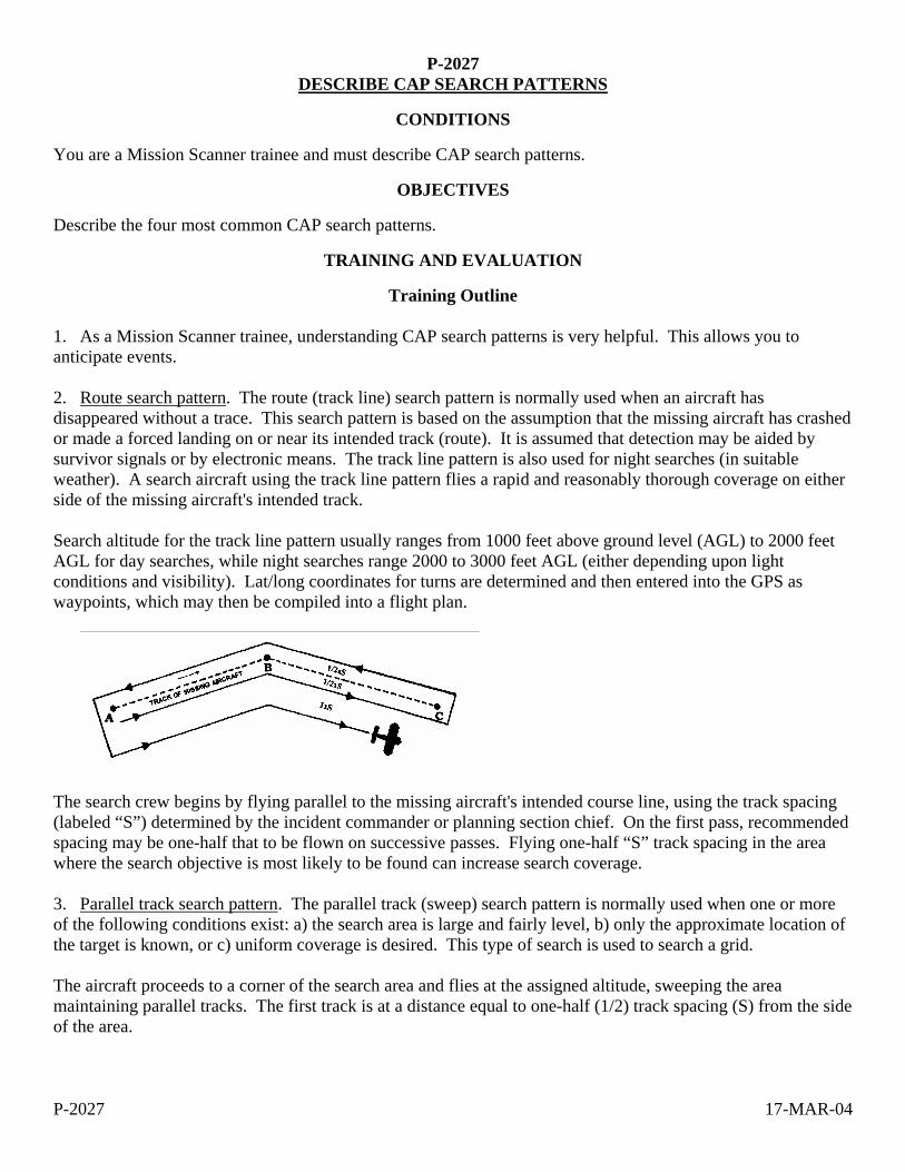
P-2027 17-MAR-04
P-2027 DESCRIBE CAP SEARCH PATTERNS
CONDITIONS
You are a Mission Scanner trainee and must describe CAP search patterns.
OBJECTIVES
Describe the four most common CAP search patterns.
TRAINING AND EVALUATION
Training Outline 1. As a Mission Scanner trainee, understanding CAP search patterns is very helpful. This allows you to anticipate events. 2. Route search pattern. The route (track line) search pattern is normally used when an aircraft has disappeared without a trace. This search pattern is based on the assumption that the missing aircraft has crashed or made a forced landing on or near its intended track (route). It is assumed that detection may be aided by survivor signals or by electronic means. The track line pattern is also used for night searches (in suitable weather). A search aircraft using the track line pattern flies a rapid and reasonably thorough coverage on either side of the missing aircraft's intended track. Search altitude for the track line pattern usually ranges from 1000 feet above ground level (AGL) to 2000 feet AGL for day searches, while night searches range 2000 to 3000 feet AGL (either depending upon light conditions and visibility). Lat/long coordinates for turns are determined and then entered into the GPS as waypoints, which may then be compiled into a flight plan.
The search crew begins by flying parallel to the missing aircraft's intended course line, using the track spacing (labeled “S”) determined by the incident commander or planning section chief. On the first pass, recommended spacing may be one-half that to be flown on successive passes. Flying one-half “S” track spacing in the area where the search objective is most likely to be found can increase search coverage. 3. Parallel track search pattern. The parallel track (sweep) search pattern is normally used when one or more of the following conditions exist: a) the search area is large and fairly level, b) only the approximate location of the target is known, or c) uniform coverage is desired. This type of search is used to search a grid. The aircraft proceeds to a corner of the search area and flies at the assigned altitude, sweeping the area maintaining parallel tracks. The first track is at a distance equal to one-half (1/2) track spacing (S) from the side of the area.

P-2027 17-MAR-04
4. Creeping line search pattern. The creeping line search pattern is similar to the parallel patterns. The parallel pattern search legs are aligned with the major, or longer, axis of the rectangular search areas, whereas the search legs of the creeping line pattern are aligned with the minor or shorter axis of rectangular search areas. The creeping line pattern is used when: a) the search area is narrow, long, and fairly level, b) the probable location of the target is thought to be on either side of the search track within two points, or c) there is a need for immediate coverage of one end of the search area. The creeping line is a succession of search legs along a line. The starting point is located one-half search track spacing inside the corner of the search area.
5. Expanding Square search pattern. The expanding square search pattern is used when the search area is small (normally, areas less than 20 miles square), and the position of the survivors is known within close limits. This pattern begins at an initially reported position and expands outward in concentric squares. If error is expected in locating the reported position, or if the target were moving, the square pattern may be modified to an expanding rectangle with the longer legs running in the direction of the target's reported, or probable, movement. If the results of the first square search of an area are negative, the search unit can use the same pattern to cover the area more thoroughly. The second search of the area should begin at the same point as the first search; however, the first leg of the second search is flown diagonally to the first leg of the first search. Consequently, the entire second search diagonally overlays the first one. The bold, unbroken line in the figure illustrates the first search, while the dashed line represents the second search. Track spacing indicated in the figure is "cumulative," showing the total width of the search pattern at a given point on that leg. Actual distance on a given leg from the preceding leg on the same side of the pattern is still only one "S," the value determined by the incident commander or planning section chief.
P-2027 17-MAR-04
Additional Information
More detailed information and figures on this topic are available in Chapter 11 of the MART.
Evaluation Preparation
Setup: Provide the student with a sectional and descriptions of each search pattern.
Brief Student: You are a Scanner trainee asked to describe the most common CAP search patterns.
Evaluation
Performance measures Results
1. Describe the following search patterns:
a. Route P F
b. Parallel P F
c. Creeping line P F
d. Expanding square P F
Student must receive a pass on all performance measures to qualify in this task. If the individual fails any measure, show what was done wrong and how to do it correctly.
P-2028 1-MAR-04
P-2028 DISCUSS CREW RESOURCE MANAGEMENT
CONDITIONS
You are a Mission Observer trainee and must discuss Crew Resource Management (CRM).
OBJECTIVES
Discuss how CRM is used in CAP activities and missions.
TRAINING AND EVALUATION
Training Outline 1. As a Mission Observer trainee, knowing how to employ effective crew resource management is essential to safety. 2. Situational Awareness. Simply put, situational awareness (SA) is "knowing what is going on around you at all times." SA is not restricted to just pilots -- everyone must exhibit SA at all times. Each crewmember must have their SA at peak levels while flying because it takes everyone’s awareness to keep the plane safe in flight. Scanners and observers have their own unique positions and functions that require full attention, so their SA is essential to the safe operation of any CAP flight. Examples of good SA attitudes are: Good mental health, where each crewmember is clear and focused. Good physical health: this includes fatigue, sickness, hydration, and stress factors. Attentiveness: keep your attention on the task at hand. Inquisitiveness: always asking questions, challenging ideas, and asking for input. Examples of SA skills: Professional skills developed through training, practice and experience. Good communication skills. These are necessary to effectively get your point across or receive valid input. Interpersonal skills such the basic courtesies factor greatly into how a crew will get along, and this will greatly impact crew effectiveness and performance. To help prevent a loss of SA, use the "IMSAFE" guidelines. This checklist was developed for the FAA as a quick memory guide for aviators to run through and make self-determination as to their fitness to fly. If a crewmember says yes to any of these, they really shouldn’t fly. There are a number of standardized tools that can help improve CRM and overcome a loss of situational awareness. When a crew loses SA it is critical to reduce workload and threats: a. Suspend the mission. [Remember to "Aviate, Navigate and Communicate."] b. Get away from the ground and other obstacles (e.g., climb to a safe altitude). c. Establish a stable flight profile where you can safely analyze the situation. Once we have lost situational awareness, or recognized the loss in another crewmember, how do we get it back? A few methods are to: a. Listen to your gut feelings. If it acts like an idiot and talks like an idiot, then its probably an idiot.
P-2028 1-MAR-04
b. Use terms like "Time Out" or "Abort" or "This is Stupid." Once terms like these are called, the pilot should terminate the task or maneuver, climb away from the ground if necessary, establish straight-and-level flight and then discuss the problem. [The term you use should be agreed upon before the flight.] c. Keep the cockpit sterile -- keep talk to the minimum necessary for safety, particularly during taxi, takeoff, departure, low-level flying, approach, and landing. This helps remove distractions and keep everyone focused on the important things. 3. Barriers to Communication. Rank, gender, experience level, age, personality, and general attitudes can all cause barriers to communication. You may occasionally be hesitant to offer an idea for fear of looking foolish or inexperienced. You may also be tempted to disregard ideas that come from individuals that have a lower experience level. If you are committed to teamwork and good crew coordination, you must look through such emotions and try to constructively and sensitively adapt to each personality involved. You can deal best with personalities by continually showing personal and professional respect and courtesy to your teammates. Criticism will only serve to build yet another barrier to good communication. Nothing breaks down a team effort faster than hostility and resentment. Always offer opinions or ideas respectfully and constructively. Instead of telling the pilot, "You're wrong," tell him what you think is wrong, such as "I think that new frequency was 127.5, not 127.9." Personal factors, including individual proficiency and stress, may also create barriers to good communication. Skills and knowledge retention decrease over time, and that is why regular training is necessary. If you don’t practice regularly, you very likely will spend a disproportionate amount of time on normal tasks, at the expense of communication and other tasks. Civil Air Patrol, the FAA, commercial airlines, and the military services all require certain minimum levels of periodic training for the sole purpose of maintaining proficiency. Stress can have a very significant, negative effect on cockpit communication. An individual's preoccupation with personal, family, or job-related problems distracts him or her from paying complete attention to mission tasks and communication, depending upon the level and source of stress. The flight itself, personalities of the individuals, distractions, flight conditions, and individual performance can all be sources of communication-limiting stress. When stress reaches very high levels, it becomes an effective barrier to communication and job performance. Many fliers and medical specialists advocate refraining from flying or other complex tasks until the stress is removed. Part of your job is also to recognize when others are not communicating and not contributing to the collective decision-making process. Occasionally, other crewmembers may need to be actively brought back into the communication process. This can often be done with a simple “What do you think about that?” In a non-threatening way, this invites the teammate back into the communication circle, and, in most cases, he or she will rejoin the information loop. 4. Task Saturation. At times, crews or individual members may be confronted with too much information to manage, or too many tasks to accomplish in the available time. This condition is referred to as task saturation. This will most likely happen when a crewmember is confronted with a new or different situation such as an emergency, bad weather, or motion sickness. Preoccupation with the different situation may then lead to a condition of “tunnel vision,” where the individual can lose track of many other important conditions. In an advanced state, comprehension is so far gone that partial or complete situational awareness is lost. When individuals are task saturated to this extent, communication and information flow usually ceases. If you begin to feel overwhelmed by information or the sheer number of things to do, it's time to evaluate each task and do only those tasks that are most important. If you ever feel over-tasked, you have an obligation to tell the other crewmembers before becoming task-saturated and losing your situational awareness. If others know your performance is suffering, they may assume some of the workload, if they are able. Once the most
P-2028 1-MAR-04
important tasks are accomplished and as time permits, you can start to take back some of those tasks that were neglected earlier. Allocation of time and establishing priorities is known as time management. Most people can recognize task saturation and understand how it can affect performance. However, you should also watch for these symptoms in other members of your crew and take over some of their responsibilities if you have the qualifications and can do so without placing your own duties at risk. The pilot's job is to safely fly the aircraft, and you should be very concerned if he or she becomes task saturated, or spends an excessive amount of his time with tasks other than flying the airplane. No crewmember should ever allow the work management situation to deteriorate to such an extent as to adversely affect the pilot's ability to continue to safely operate the aircraft. Many preventable accidents have resulted from crews’ entire involvement in other areas or problems, while the airplane literally flew into the ground. If any crewmember suspects pilot task saturation to be the case, nonessential discussion should cease, and the crew as a whole should discontinue low-priority aspects of the job, and even return to the mission base if necessary. 5. Assignments and Coordination of Duties. Assignment of aircrew duties is based on CAPR 60-3. All flight-related duties are conducted under the supervision of the aircraft commander. Mission-related duties may also be conducted under the supervision of the aircraft commander, but a properly trained observer can also fill the role of mission commander. The key is that positive delegation of monitoring duties is as important as positive delegation of flying duties. As previously discussed, it is very important for each crewmember to know what they are supposed to be doing at all times and under all conditions. Aircraft safety duties vary with the start up, taxi, takeoff, departure, transit, approach and landing phases of flight. Mission duties are related to the mission objective, primarily to fly the aircraft safely and precisely (the pilot) and to scan effectively (scanners and observers). Close attention should be paid during the pilot’s briefing. The pilot will establish flight-specific safety "bottom lines" at this time, such as emergency duties and division of responsibilities. Each individual must again clearly understand his specific assigned duties and responsibilities before proceeding to the aircraft. Other phases of the flight also require that distractions be kept to a minimum. Recent air transport industry statistics show that 67% of airline accidents during a particular survey period happened during only 17% of the flight time -- the taxi, takeoff, departure, approach and landing phases. The FAA has designated these phases of flight as critical, and has ruled that the cockpit environment must be free of extraneous activity and distractions during these phases to the maximum extent possible (the sterile cockpit). In assigning scanning responsibilities to the scanners, mission observers must be receptive to questions and suggestions from the scanners. Carefully consider suggestions and understand that suggestions are almost always offered constructively, and are not intended to be critical. Answer questions thoroughly and openly, and don’t become defensive. All doubts or questions that you can’t answer should be resolved as soon as possible. It is critical to remember that CRM encourages the flow of ideas, but the Mission Pilot must make the final decision based on the crew's input.
Additional Information
More detailed information on this topic is available in Chapter 14 of the MART.

P-2028 1-MAR-04
Evaluation Preparation
Setup: None.
Brief Student: You are a Mission Observer trainee asked to discuss CRM.
Evaluation
Performance measures Results
1. Discuss situational awareness and how to regain SA once it is lost. P F
2. Describe barriers to communication. P F
3. Discuss task saturation and strategies to minimize it. P F
4. Discuss crew assignments and coordination of duties. P F
Student must receive a pass on all performance measures to qualify in this task. If the individual fails any measure, show what was done wrong and how to do it correctly.

Advanced Training Tasks

O-0204 17-MAR-04
O-0204 LOCATE A POINT ON A MAP USING LATITUDE AND LONGITUDE
CONDITIONS
Given an aeronautical chart, road map, or topographical map with latitude and longitude lines. You are away from mission base, mounted or dismounted, and must locate your location on map in order to report your location to mission base, an aircraft or another ground element using latitude and longitude. Or, you are coordinating with another search element (ground or air) who has told you his location using the latitude and longitude. You want to plot this point on your map.
OBJECTIVES Within 1 minute, the team member announces the correct latitude and longitude of the marked point (using the smallest gradiations of latitude and longitude printed on the map), using correct terminology, and, within 1 minute, can plot a point on the map given the latitude and longitude orally.
TRAINING AND EVALUATION
Training Outline 1. Latitude and longitude are the objective position measurements used on aeronautical charts. Many road maps and topographical maps also are gridded using this system. a. Lines of longitude run north-south on the map. Lines of latitude run east-west. b. Both latitude and longitude are measured in degrees, minutes and seconds. One minute is 1/60th of a degree, and one second is 1/60th of a minute. In the continental US, latitude numbers are read from south to north (bottom to top), and longitude numbers are read from east to west (right to left) c. Each line of latitude is labeled as either North (if it is above the equator) or South (if it is below the equator). Each line of longitude is labeled as East (if it is east of a longitude line called the Prime Meridian) or West (if it is west of the Prime Meridian) d. To read a lat-long coordinates the symbol “ ° “ means degrees, an apostrophe ( “ ‘ “) means minutes, and a double apostrophe (“ “ “) means seconds. Always read the latitude before the longitude. e. Example: 32° 33’ 44” N, 45° 12’ 52” E means “32 degrees, 33 minutes, and 44 seconds North Latitude, 45 degrees 12 minutes and 52 seconds East Longitude” f. On larger scale maps, or when pinpoint accuracy is not required, seconds are not used. For example, 45° 12’ N, 22° 36 W is read as “45 degrees, 12 minutes North Latitude, 22 degrees 36 minutes West Longitude.” 2. To find the lat-long designation of a known point on the map a. Find the latitude: 1) Find the numbers of the latitude degree lines to the immediate north and south of the point. Write down the lower of the two. (For example, if the point is between 45° and 46° North latitude, write down

O-0204 17-MAR-04
“45°“. Also write down if that latitude line is labeled as “North” or “South” (above the equator it will always be “North”). 2) From latitude line chosen above, count up the number of minutes that the point is from the line using the tick marks on the edge of the map (or in the grids if the map is gridded) until you reach the last minute marking before your point. Write down the number of minutes. 3) From the last minute mark, count up the number of seconds to your point (if the map is of a large scale, such as an aviation chart, it will not have marks for seconds. Either stop with the minute measurement, or estimate seconds). Write down the number of seconds. b. Find the longitude. 1) Find the numbers of the longitude degree lines to the immediate east and west of the point. Write down the lower of the two. (For example, if the point is between 22° and 23° West latitude, write down “ 22° “). Also write down if that latitude line is labeled as “East” or “West” (in the western hemisphere it will always be “West”). 2) From longitude line chosen above, count left the number of minutes that the point is from the line using the tick marks on the edge of the map (or in the grids if the map is gridded) until you reach the last minute marking before your point. Write down the number of minutes. 3) From the last minute mark, count left the number of seconds to your point (if the map is of a large scale, such as an aviation chart, it will not have marks for seconds. Either stop with the minute measurement, or estimate seconds). Write down the number of seconds. c. NOTE: If the map is not marked with minutes or seconds, you will have to estimate. Remember, there are 60 minutes in a degree and 60 seconds in a minute. So, if the point is halfway between two degrees, it is at the 30 minute point. If it is one quarter the distance from one degree to another, it is at the 15 minute point. Use the same logic to determine seconds if the map is only gradiated in degrees and minutes. c. Make sure the lat-long coordinate you have written down is in the format Degrees°, Minutes’, Seconds” (North or South) Latitude, Degrees°, Minutes’, Seconds” (East or West) Longitude, 3. To plot a point given the lat-long coordinate: a. Find the correct latitude line and count up the correct number of minutes and seconds (below the equator you would count down, not up). b. Find the correct longitude line and count left the correct number of minutes and seconds (in the eastern hemisphere you would count right, not left). c. Mark the point.
Additional Information
More detailed information on this topic is available in the Ground Team Member and Leader Reference Text and Mission Aircrew Reference Text.

O-0204 17-MAR-04
Evaluation Preparation Setup: Mark a point on a map or chart gridded with latitude and longitude, and give the map to the student. . Tell him whether or not he must report seconds, or just degrees and minutes (depends on the scale of the map). Pick a different grid location from the point and write down the latitude and longitude coordinates. Ensure you have a timer. Because this task is timed, it is necessary to make sure that the student and work area is prepared for testing. The map should be open and complete. If copies of maps are used, they should include all references normally available on the full map to take the exam. Brief Student: Ask the student if he is prepared. Tell the student to tell you the latitude and longitude of the point. Then orally give him the latitude and longitude you wrote down and tell him to show you where that point is on the map.
Evaluation
Performance Measures Results Determining the grid of a known point. The student: 1. Announces the correct latitude degrees, minutes and seconds within tolerance (see below) P F 2. Announces the correct latitude designation “North” or South” P F 3. Announces the correct longitude degrees, minutes and seconds within tolerance (see below) P F 4. Announces the correct longitude designation “East” or “West” P F 5. Performs the above steps within 1 minute of time P F NOTE: The minimum accuracy for this task is to be within 30 seconds of the correct answer for a map gradiated in minutes. If the map is large enough scale to be gradiated in seconds, then the needed accuracy should be increased. For dismounted work, a ground team with proper maps should be able to plot positions within 10 seconds. The individual determines the location of a designated grid: 6. Plots a point on the map within 1 minute using the correct latitude and longitude degrees, minutes and seconds within tolerance (see accuracy note above). P F Student must receive a pass on all performance measures to qualify in this task. If the individual fails any measure, show what was done wrong and how to do it correctly.

O-0205 17-MAR-04
O-0205 LOCATE A POINT ON A MAP USING THE CAP GRID SYSTEM
CONDITIONS
Given an aeronautical chart, road map, or topographical map gridded with the CAP grid system. You are away from mission base, mounted or dismounted, and must plot your location on a CAP gridded map in order to report it, an aircraft or another ground element. Or, you are coordinating with another search element (ground or air) who has told you his location using the CAP grid system. You want to plot this point on your map.
OBJECTIVES
Within 1 minute, the team member announces the CAP grid and sub-grid that the point is located in, using correct terminology, and can plot a point on the map given the CAP grid coordinates orally.
TRAINING AND EVALUATION
Training Outline 1. The CAP grid system is designed for use on aeronautical charts, but can be adapted to any map with latitude/longitude markings around the edge. 2. A grid is a 15 minute latitude by 15 minute longitude box. This is done by dividing the 30 minute by 30 minute boxes already on the aeronautical chart into fourths. Each grid is identified with a number. (For example “I am located in Grid 54”). 3. To locate a position more precisely, mentally divide each grid into four quadrants. The Northwest quadrant is “A”, the Northeast is “B”, the Southwest is “C”, and the Southeast is “D”. Say the quadrant letter after the grid number (for example, “I am in grid 54 B”).
54 55
8382A B
C D
Example of CAP grids (54,55,82 and 83) and lettered quadrants (83A, 83B, 83C, and 83D)
4. To find the grid designation of a known point on the map a. Find the grid number the point is in.
O-0205 17-MAR-04
b. Determine which quadrant of the grid the point is in (A, B, C, or D) 5. To plot a point given a grid number and quadrant letter: a. Find the appropriate grid on the map (the grid numbers increase as you look left to right and top to bottom on the map. b. Mark the point in the appropriate lettered quadrant of that grid.
Additional Information
More detailed information on this topic is available in the Ground Team Member and Leader Reference Text and the Mission Aircrew Reference Text.
Evaluation Preparation Setup: Mark a point on a CAP gridded map or chart and give the map to the student. Pick a different grid location from the point and write down the grid and quadrant. Ensure you have a timer. Brief Student: Tell the student to tell you the CAP grid and quadrant designation of the point. Then orally give him the grid and quadrant of the point you wrote down and tell him to show you where that point is on the map.
Evaluation Performance Measures Results The individual determines the grid of a known point: 1. Announces the correct grid number and quadrant within 1 minute P F The individual determines the location of a designated grid: 2. Finds the correct numbered grid and quadrant within 1 minute P F Student must receive a pass on all performance measures to qualify in this task. If the individual fails any measure, show what was done wrong and how to do it correctly.

O-2016 1-MAR-04
O-2016 DEMONSTRATE SAFETY WHILE TAXIING
CONDITIONS
You are a Mission Scanner trainee and must demonstrate safety techniques while taxiing in an aircraft.
OBJECTIVES
Demonstrate safety while taxiing, including airport signs and markings and flightline hand signals.
TRAINING AND EVALUATION
Training Outline 1. As a Mission Scanner trainee, knowledge of safety during taxiing is essential. All crewmembers should assist the pilot while taxiing. The pilot should brief each crewmember on what direction he or she should look out the aircraft. Sterile cockpit rules are in effect, so the crew should limit their conversation to the task at hand. Report conflicts to the pilot immediately, using the "clock position" method.
a. Maintain adequate clearance from obstacles. b. When taxiing within 10 feet of obstacles stop, and then proceed no faster than a slow walk. c. If available, use marshallers or a "wing walker." d. Potential collisions with other aircraft or vehicles. e. Stay on or find the taxiway. At night or under low visibility conditions, assist the pilot. Some smaller
airports do not mark their taxiways or the paint may be faded. 2. Runway markings are white and taxiways are yellow. Taxiway centerlines are solid yellow. Some taxiway boundaries are marked with double yellow lines while others have blue lights or cones. 3. Mandatory signs have a red background with a white inscription, and are used to denote an entrance to a runway or critical area where an aircraft is prohibited from entering without ATC permission:
a. Holding position for a runway. Do not cross without ATC permission. May have a row of red stop bar lights, embedded in the pavement and extending across the taxiway at the runway holding position. When illuminated they designate a runway hold position: never cross a red illuminated stop bar, even if cleared by ATC.
b. Holding position for approach area. Do not cross without ATC permission.
c. Holding position for instrument landing system. Do not cross without ATC permission.
d. No entry. Typically placed on a one-way taxiway or at the intersection of vehicle roadways that can
be mistaken for a taxiway.
4. Holding position marking for runway boundary. Four yellow lines: two solid and two dashed. The aircraft approaches the dashed lines and stops behind the solid lines (ensures you do not enter the runway). Do not cross without ATC permission. When exiting the runway, the pilot should cross the dashed lines to make sure the aircraft is completely clear of the runway. May have yellow clearance bar lights embedded in the pavement to indicate a hold point. May have flashing yellow guard lights elevated or in-pavement at runway holding positions.

O-2016 1-MAR-04
5. Location signs are used to identify either a taxiway (letters) or runway (numbers) on which an aircraft is located, or to provide a visual clue to the aircrew when the aircraft has exited an area:
6. Direction signs gave a yellow background with a black inscription.
7. Ground crew use hand signals to help direct pilots during taxi operations. The scanner should be familiar with these signals in order to increase safety during taxiing and parking:
Circular motion of right hand at head level with left arm pointing to engine. START ENGINE
Arms above head in vertical position with palms facing inward. THIS MARSHALLER
Thumb Up. OK or YES
Thumb Down. NOT OK or NO
Outward motion with thumbs. PULL CHOCKS
Raise arm, with fist clenched, horizontally in front of body, and then extend fingers. RELEASE BRAKE
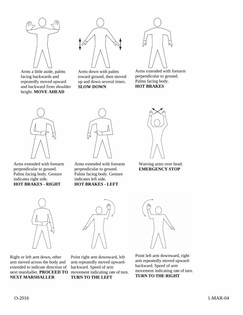
O-2016 1-MAR-04
Arms a little aside, palms facing backwards and repeatedly moved upward and backward from shoulder height. MOVE AHEAD
Arms down with palms toward ground, then moved up and down several times. SLOW DOWN
Right or left arm down, other arm moved across the body and extended to indicate direction of next marshaller. PROCEED TO NEXT MARSHALLER
Point right arm downward, left arm repeatedly moved upward-backward. Speed of arm movement indicating rate of turn. TURN TO THE LEFT
Point left arm downward, right arm repeatedly moved upward-backward. Speed of arm movement indicating rate of turn. TURN TO THE RIGHT
Arms extended with forearm perpendicular to ground. Palms facing body. HOT BRAKES
Arms extended with forearm perpendicular to ground. Palms facing body. Gesture indicates right side. HOT BRAKES - RIGHT
Arms extended with forearm perpendicular to ground. Palms facing body. Gesture indicates left side. HOT BRAKES - LEFT
Waiving arms over head. EMERGENCY STOP

O-2016 1-MAR-04
Arms crossed above the head, palms facing forward. STOP
Either arm and hand level with shoulder, hand moving across throat, palm downward. CUT ENGINES
Make rapid horizontal figure-eight motion at waist level with either arm, pointing at source of fire with the other. FIRE ONBOARD
Right arm raised with elbow at shoulder height with palm facing forward. MARSHALLER
Make a chopping motion with one hand slicing into the flat and open palm of the other hand. Number of fingers extended on left hand indicates affected engine. FEATHER / FUEL SHUT-OFF
Raise arm and hand, with fingers extended horizontally in front of the body, then clench fist. ENGAGE BRAKE
Inward motion with thumbs. INSERT CHOCKS
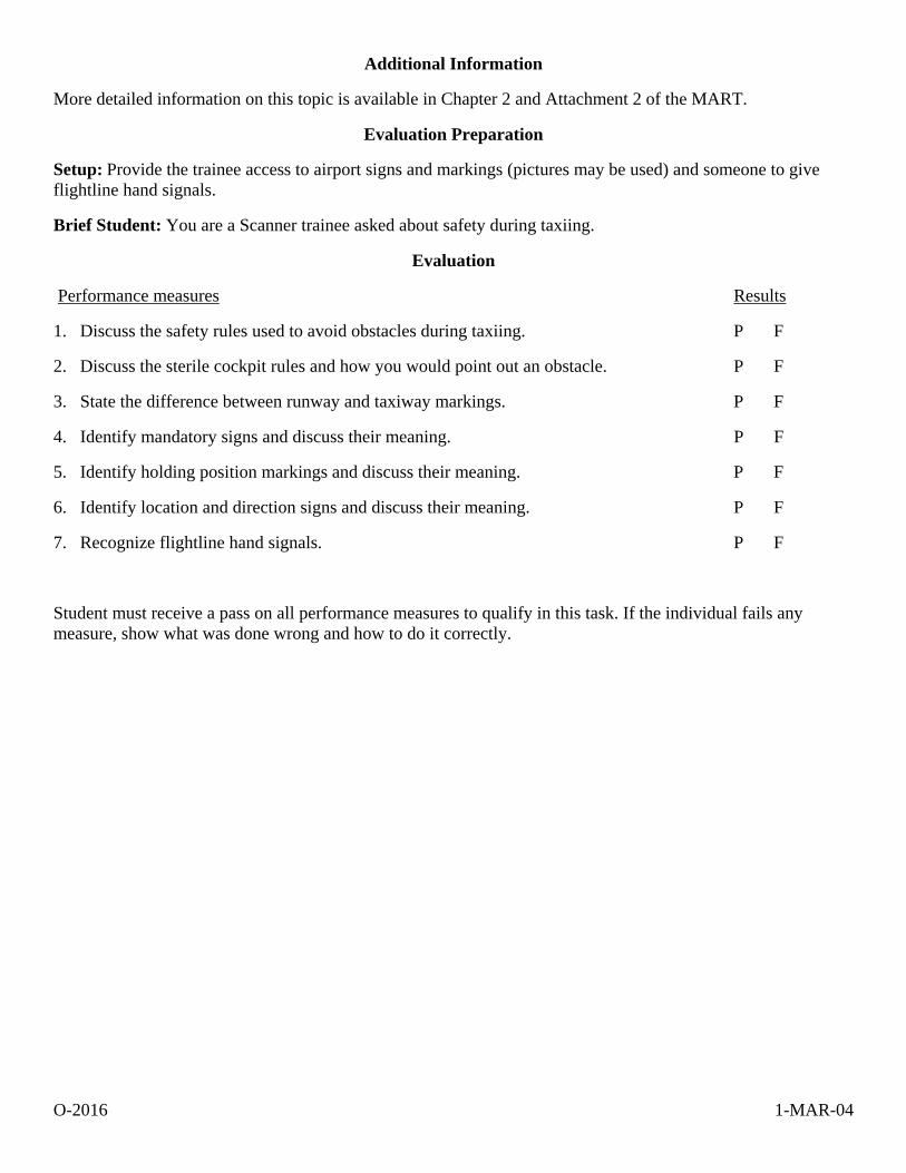
O-2016 1-MAR-04
Additional Information
More detailed information on this topic is available in Chapter 2 and Attachment 2 of the MART.
Evaluation Preparation
Setup: Provide the trainee access to airport signs and markings (pictures may be used) and someone to give flightline hand signals.
Brief Student: You are a Scanner trainee asked about safety during taxiing.
Evaluation
Performance measures Results
1. Discuss the safety rules used to avoid obstacles during taxiing. P F
2. Discuss the sterile cockpit rules and how you would point out an obstacle. P F
3. State the difference between runway and taxiway markings. P F
4. Identify mandatory signs and discuss their meaning. P F
5. Identify holding position markings and discuss their meaning. P F
6. Identify location and direction signs and discuss their meaning. P F
7. Recognize flightline hand signals. P F
Student must receive a pass on all performance measures to qualify in this task. If the individual fails any measure, show what was done wrong and how to do it correctly.

O-2018 1-MAR-04
O-2018 OPERATE THE AIRCRAFT COMMUNICATIONS EQUIPMENT
CONDITIONS
You are a Mission Scanner trainee and must operate and discuss the aircraft communications equipment.
OBJECTIVES
Demonstrate basic knowledge and use of the aircraft communications radios and the CAP FM radio. Demonstrate how to set up the audio panel to use the radios.
TRAINING AND EVALUATION
Training Outline 1. As a Mission Scanner trainee, basic knowledge of aircraft communications equipment is essential. Although you will probably only use the FM radio during missions, knowledge of how to use the other communications equipment could prove very important during emergencies. 2. Aircraft radios. The radios used in CAP aircraft are normally combined with navigation receivers, and so are often referred to as "nav/comm" radios. Each radio (there are usually two) has a 'primary' and a 'standby' function (called "flip-flop"): the primary frequency is displayed on the left and the standby frequency on the right. To use a frequency it must be in the primary display; to change a frequency, it must be in the standby display. The frequencies are normally tuned in increments of 50 kilocycles, for example 119.70 or 119.75 (the last '0' is not displayed). They can also be tuned in increments of 25 kilocycles by pulling out on the tuning knob and turning, but the last '5' will not be shown in the display (e.g., 119.775 will be displayed as 119.77). Sometimes, for brevity, air traffic controllers assign such frequencies as "one-one nine point seven seven," meaning 119.775, not 119.770. The operator cannot physically tune the radio to 119.770, and this may be confusing.
3. Before transmitting on any radio, first listen to the selected frequency. An untimely transmission can "step on" another transmission from either another airplane or ground facility, so that all the transmissions are garbled. Next, mentally prepare your message so that the transmission flows naturally without unnecessary pauses and breaks (think "Who, Where and What"). You may even find it helpful to jot down what you want to say before beginning the transmission. When you first begin using the radio, you may find abbreviated notes to be a convenient means of collecting thoughts with the proper terminology. As your experience level grows, you may find it no longer necessary to prepare using written notes. 4. CAP aircraft callsigns are pronounced "Cap Flight XX XX," where the numbers are those assigned to each Wing's aircraft. The numbers are stated in 'group' form. For example, the C172 assigned to Amarillo, Texas is numbered 4239, where 42 is the prefix identifying it as a Texas Wing aircraft. The callsign is thus pronounced "Cap Flight Forty-Two Thirty-Nine." It is important to use the group form of pronunciation because FAA air traffic controllers expect it of us. 5. CAP VHF FM radio. This radio is dedicated to air to ground communications, and is normally operated by the observer or scanner. Several of the frequencies programmed into the radio are frequencies assigned to CAP by the U.S. Air Force, and are used to communicate with CAP bases and ground teams. Others are

O-2018 1-MAR-04
programmed at the direction of the Wing Communications Officer (e.g., mutual aid, fire, police, park service, forest service, and department of public service); these frequencies almost always require prior permission from the controlling agency before use. There are currently three types of FM radios in use in the CAP fleet at this time. Refer to your aircraft's operating manual for specific details for its use. Chapter 4 of the Mission Aircrew Reference Text provides directions on the use of the TDFM-136. 6. Audio panel. The audio panel serves as the 'hub' of radio communications in the aircraft, and is normally set up by the pilot or observer. The scanner needs to know how to select the 'active' aircraft communications radio for transmission. The active radio is selected with the switch on the right-hand side of the panel. Select either COM 1 or COM 2 to transmit and receive on the frequency displayed in the associated radio's primary display.
Additional Information
More detailed information on this topic is available in Chapter 4 of the MART.
Evaluation Preparation
Setup: Provide the student access to aircraft radios or detailed figures.
Brief Student: You are a Scanner trainee asked about using the aircraft radios.
Evaluation
Performance measures Results
1. Demonstrate how to enter a frequency and use the aircraft communications radios. P F
2. Discuss the importance of listening before transmitting, and basic message format. P F
3. Demonstrate proper use of the CAP aircraft callsign. P F
4. Demonstrate how to select a frequency and use the CAP FM radio. P F
5. Demonstrate setting up the audio panel to transmit on an aircraft radio. P F
Student must receive a pass on all performance measures to qualify in this task. If the individual fails any measure, show what was done wrong and how to do it correctly.
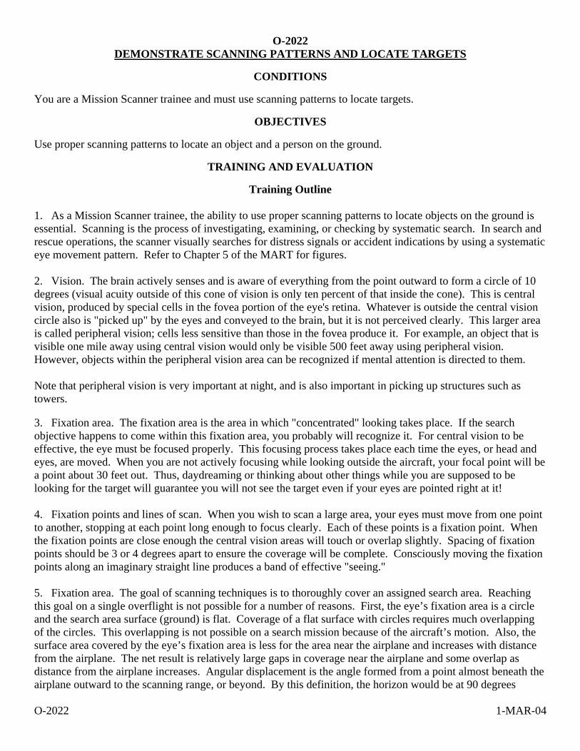
O-2022 1-MAR-04
O-2022 DEMONSTRATE SCANNING PATTERNS AND LOCATE TARGETS
CONDITIONS
You are a Mission Scanner trainee and must use scanning patterns to locate targets.
OBJECTIVES
Use proper scanning patterns to locate an object and a person on the ground.
TRAINING AND EVALUATION
Training Outline 1. As a Mission Scanner trainee, the ability to use proper scanning patterns to locate objects on the ground is essential. Scanning is the process of investigating, examining, or checking by systematic search. In search and rescue operations, the scanner visually searches for distress signals or accident indications by using a systematic eye movement pattern. Refer to Chapter 5 of the MART for figures. 2. Vision. The brain actively senses and is aware of everything from the point outward to form a circle of 10 degrees (visual acuity outside of this cone of vision is only ten percent of that inside the cone). This is central vision, produced by special cells in the fovea portion of the eye's retina. Whatever is outside the central vision circle also is "picked up" by the eyes and conveyed to the brain, but it is not perceived clearly. This larger area is called peripheral vision; cells less sensitive than those in the fovea produce it. For example, an object that is visible one mile away using central vision would only be visible 500 feet away using peripheral vision. However, objects within the peripheral vision area can be recognized if mental attention is directed to them. Note that peripheral vision is very important at night, and is also important in picking up structures such as towers. 3. Fixation area. The fixation area is the area in which "concentrated" looking takes place. If the search objective happens to come within this fixation area, you probably will recognize it. For central vision to be effective, the eye must be focused properly. This focusing process takes place each time the eyes, or head and eyes, are moved. When you are not actively focusing while looking outside the aircraft, your focal point will be a point about 30 feet out. Thus, daydreaming or thinking about other things while you are supposed to be looking for the target will guarantee you will not see the target even if your eyes are pointed right at it! 4. Fixation points and lines of scan. When you wish to scan a large area, your eyes must move from one point to another, stopping at each point long enough to focus clearly. Each of these points is a fixation point. When the fixation points are close enough the central vision areas will touch or overlap slightly. Spacing of fixation points should be 3 or 4 degrees apart to ensure the coverage will be complete. Consciously moving the fixation points along an imaginary straight line produces a band of effective "seeing." 5. Fixation area. The goal of scanning techniques is to thoroughly cover an assigned search area. Reaching this goal on a single overflight is not possible for a number of reasons. First, the eye’s fixation area is a circle and the search area surface (ground) is flat. Coverage of a flat surface with circles requires much overlapping of the circles. This overlapping is not possible on a search mission because of the aircraft’s motion. Also, the surface area covered by the eye’s fixation area is less for the area near the airplane and increases with distance from the airplane. The net result is relatively large gaps in coverage near the airplane and some overlap as distance from the airplane increases. Angular displacement is the angle formed from a point almost beneath the airplane outward to the scanning range, or beyond. By this definition, the horizon would be at 90 degrees
O-2022 1-MAR-04
displacement. Although the fixation area may be a constant 10-degree diameter circle, the effectiveness of sighting the objective decreases with an increase in this angular displacement. Said another way, your ability to see detail will be excellent at a point near the aircraft, but will decrease as the angular displacement increases. At the scanning range, at which the angular displacement may be as much as 45 degrees, the resolution of detail area probably will have shrunk to a 4-degree diameter circle. This is why having scanners looking out both sides of the aircraft is optimal. With track spacing (explained later) proper for the given search visibility, each scanner will look at roughly the same area (i.e., double coverage). 6. Field of scan. The area that you will search with your eyes in lines of scan is called the field of scan. The upper limit of this field is the line that forms the scanning range. The lower limit is the lower edge of the aircraft window, while the aft (back) limit is usually established by the vertical edge of the aircraft window. The forward (front) limit for a field of scan will vary. It might be established by a part of the airplane (such as a wing strut). Or, when two scanners are working from the same side of the airplane it might be limited by an agreed-upon point dividing the field of scan. 7. Scanning range. We are using the term “scanning range” to describe the distance from an aircraft to an imaginary line parallel to the aircraft’s ground track (track over the ground.) This line is the maximum range at which a scanner is considered to have a good chance at sighting the search objective. Scanning range sometimes may be confused with search visibility range. Search visibility range is that distance at which an object the size of an automobile can be seen and recognized. Aircraft debris may not be as large as an automobile and may not be immediately recognizable as aircraft debris, particularly when the aircraft is flying at 100 mph. Therefore, scanning range may be less than but never greater than the search visibility (in CAP searches, we rarely credit a search visibility of greater than three or four nautical miles). If your pilot states that the search altitude will be 500 feet above the ground level (AGL), you can expect your scanning range to be ¼ to ½ mile. If the search altitude is 1,000 feet AGL, you can expect a scanning range of between ½ and 1 mile. Even so, there are many variables that affect both the effective scanning range and your probability of detecting the search objective. These issues are discussed later. 8. Scanning patterns. To cover the field of scan adequately requires that a set pattern of scan lines be used. Research into scanning techniques has shown that there are two basic patterns that provide the best coverage. These are called the diagonal pattern and the vertical pattern. The diagonal pattern is the better of the two. The diagonal pattern begins with the first fixation point slightly forward of the aircraft's position, and the scanner moves her fixation points sequentially back toward the aircraft. The next scan line should be parallel to the first, and so on. Each succeeding scan line is started as quickly as possible after completing the previous one. Remember, the duration of each fixation point along a scan line is about 1/3 second: how long it takes to complete one scan line depends on the distance at which the scanning range has been established. Also, the time required to begin a new scan line has a significant influence on how well the area nearest the airplane is scanned. In other words, more time between starting scan lines means more space between fixation points near the airplane. The vertical pattern is somewhat less effective. You should use this pattern only from a rear seat position, and the first fixation point should be as near to underneath the airplane as you can see. Subsequent fixation points for this first scan line should progress outward to the scanning range and back. This scanning pattern traces a "sawtooth" shape on the surface. Note: If there are two scanners on the same side of the airplane, it is good practice to combine the diagonal and vertical patterns. As agreed between scanners, one would use the diagonal pattern and the other the vertical pattern. However, the scanner using the vertical pattern would not scan to the scanning range. Some distance

O-2022 1-MAR-04
short of the scanning range would be selected as the vertical pattern limit. This technique provides good coverage of the surface area near the search aircraft.
Additional Information
More detailed information and pictures on this topic are available in Chapter 5 of the MART.
Evaluation Preparation
Setup: Provide the student with an aircraft and aircrew (scanning techniques may be simulated on the ground).
Place a target (preferably to simulate aircraft wreckage) in the search area, and have a person (or mannequin) in the same general area. Fly the search area at 1000' AGL and 90-100 knots.
Brief Student: You are a Scanner trainee asked to demonstrate scanning patterns and locate targets in a search area.
Evaluation
Performance measures Results
1. Define "scanning" and "fixation," and describe how aircraft motion effects scanning. P F
2. Demonstrate knowledge of central and peripheral vision, and describe where your focal point is when your eyes are relaxed. P F
3. Demonstrate knowledge of fixation points and lines of scan, and define "scanning range." P F
4. Demonstrate diagonal and vertical scanning patterns. P F
5. Locate a target in a search area. P F
6. Locate a person in a search area. P F
Student must receive a pass on all performance measures to qualify in this task. If the individual fails any measure, show what was done wrong and how to do it correctly.

O-2023 1-MAR-04
O-2023 DEMONSTRATE TECHNIQUES TO REDUCE FATIGUE
CONDITIONS
You are a Mission Scanner trainee and must demonstrate and discuss how to minimize fatigue.
OBJECTIVES
Demonstrate techniques to minimize fatigue, and how you would direct the pilot during flight.
TRAINING AND EVALUATION
Training Outline 1. As a Mission Scanner trainee, knowing how to minimize fatigue is essential. The art of scanning is more physically demanding and requires greater concentration than mere sight seeing. In order to maintain scanning effectiveness you must be aware of your own fatigue level. The following can help maintain scanning effectiveness: a. Change scanning positions at 30- to 60-minute intervals, if aircraft size permits. b. Rotate scanners from one side of the aircraft to the other, if two or more scanners are present. c. Find a comfortable position, and move around to stretch when necessary. d. Clean aircraft windshields and windows. Dirty windows accelerate the onset of eye fatigue, and can reduce
visibility by up to 50 percent. e. Scan through open hatches whenever feasible. f. At night, use red lights and keep them dimmed to reduce reflection and glare. g. Use binoculars (sparingly) to check sightings. h. Focus on a close object (like the wing tip) on a regular basis. The muscles of the eye get tired when you
focus far away for an extended period of time. i. Rest during turns outside the search area. 2. The "clock position" system is used to describe the relative positions of everything outside the airplane, with the nose of the aircraft being "12 o'clock." The system considers positions to be on a horizontal plane that is centered within the cockpit, and any object above or below this plane is either "high" or "low."
Additional Information
More detailed information on this topic is available in Chapter 5 of the MART.
Evaluation Preparation
Setup: Provide the student access to an aircraft (may simulate on the ground).
Brief Student: You are a Scanner trainee asked how to minimize fatigue during searches.
Evaluation
Performance measures Results
1. Discuss fatigue effects and demonstrate how to minimize fatigue. P F
2. Describe how to direct the pilot using the "clock position" method. P F
Student must receive a pass on all performance measures to qualify in this task. If the individual fails any measure, show what was done wrong and how to do it correctly.

O-2025 1-MAR-04
O-2025 TRACK AND RECORD POSITION ON SECTIONALS AND MAPS
CONDITIONS
You are a Mission Scanner trainee and must demonstrate basic use of navigational terms, determine heading and distance, and determine the position of the aircraft and ground features.
OBJECTIVES
Demonstrate basic knowledge and use of navigational terms. Determine the aircraft's heading and the distance between two points. Given a sectional chart, record a ground feature and transfer that location to a map.
TRAINING AND EVALUATION
Training Outline 1. As a Mission Scanner trainee, a basic knowledge of navigational terms, the ability to determine heading and distance, and the ability to record a ground feature on a sectional and a map is essential. In order to effectively communicate with the pilot and ground units, the mission scanner must have a clear understanding of various terms that are used frequently when flying aboard CAP aircraft. These are not peculiar to search and rescue, but are used by all civilian and military aviators. The scanner must also be able to track the aircraft's position, and relay the location of ground features to both the pilot and observer and units on the ground. 2. Course. Course refers to the planned or actual path of the aircraft over the ground. The course can be either true course or magnetic course depending upon whether it is measured by referencing true north or magnetic north. The magnetic north pole is not located at the true North Pole on the actual axis of rotation, so there is usually a difference between true course and magnetic course. 3. Heading. Heading is the direction the aircraft is physically pointed. True heading is based on the true North Pole, and magnetic heading is based on the magnetic north pole. Most airplane compasses can only reference magnetic north without resorting to advanced techniques or equipment, so headings are usually magnetic. 6. Drift is the effect the wind has on an aircraft. The motion of the airplane relative to the surface of the earth depends upon the fact that the airplane is moving relative to an air mass and the air mass is moving relative to the surface of the earth. Adding these two gives the resultant vector of the airplane moving relative to the surface of the earth. The angle between the heading and the actual ground track is called the drift angle. Drift is corrected by changing the aircraft's heading just enough to negate drift. 5. Ground track. The actual path of the airplane over the surface of the earth is called the ground track. An airplane's track over the ground doesn't always correspond with the direction it's pointed (heading). This is due to the effect of wind (drift). All GPS units will display ground track. 6. A nautical mile is about 6076 feet (sometimes rounded to 6080 feet), compared to 5280 feet for the statute mile. Most experienced aviators simply refer to a nautical mile as a mile. Scanners and Observers should remain aware of this difference when communicating with ground search teams because most ground or surface distances are measured using statute miles or kilometers. To convert nautical miles into statute miles, multiply nautical miles by 1.15. To find kilometers, multiply nautical miles by 1.85. Also, one nautical mile is equal to one minute of latitude: this provides a convenient scale for measuring distances on any chart. Nautical miles are abbreviated "nm".
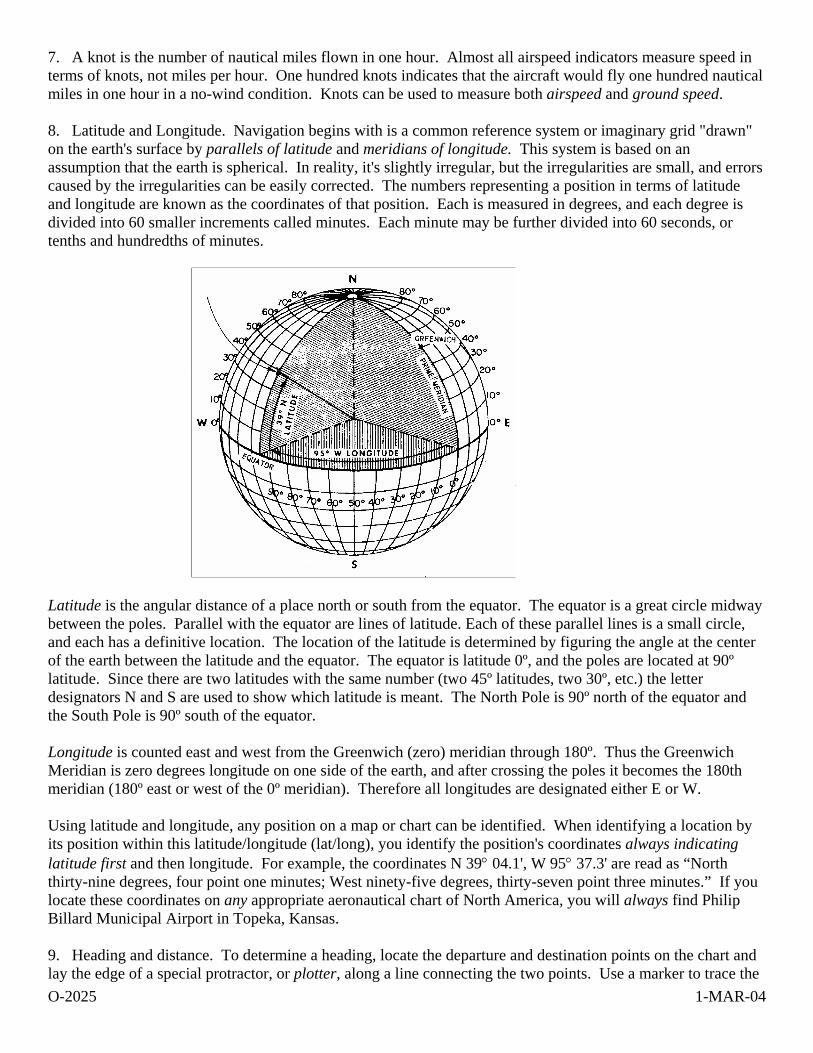
O-2025 1-MAR-04
7. A knot is the number of nautical miles flown in one hour. Almost all airspeed indicators measure speed in terms of knots, not miles per hour. One hundred knots indicates that the aircraft would fly one hundred nautical miles in one hour in a no-wind condition. Knots can be used to measure both airspeed and ground speed. 8. Latitude and Longitude. Navigation begins with is a common reference system or imaginary grid "drawn" on the earth's surface by parallels of latitude and meridians of longitude. This system is based on an assumption that the earth is spherical. In reality, it's slightly irregular, but the irregularities are small, and errors caused by the irregularities can be easily corrected. The numbers representing a position in terms of latitude and longitude are known as the coordinates of that position. Each is measured in degrees, and each degree is divided into 60 smaller increments called minutes. Each minute may be further divided into 60 seconds, or tenths and hundredths of minutes.
Latitude is the angular distance of a place north or south from the equator. The equator is a great circle midway between the poles. Parallel with the equator are lines of latitude. Each of these parallel lines is a small circle, and each has a definitive location. The location of the latitude is determined by figuring the angle at the center of the earth between the latitude and the equator. The equator is latitude 0º, and the poles are located at 90º latitude. Since there are two latitudes with the same number (two 45º latitudes, two 30º, etc.) the letter designators N and S are used to show which latitude is meant. The North Pole is 90º north of the equator and the South Pole is 90º south of the equator. Longitude is counted east and west from the Greenwich (zero) meridian through 180º. Thus the Greenwich Meridian is zero degrees longitude on one side of the earth, and after crossing the poles it becomes the 180th meridian (180º east or west of the 0º meridian). Therefore all longitudes are designated either E or W. Using latitude and longitude, any position on a map or chart can be identified. When identifying a location by its position within this latitude/longitude (lat/long), you identify the position's coordinates always indicating latitude first and then longitude. For example, the coordinates N 39° 04.1', W 95° 37.3' are read as “North thirty-nine degrees, four point one minutes; West ninety-five degrees, thirty-seven point three minutes.” If you locate these coordinates on any appropriate aeronautical chart of North America, you will always find Philip Billard Municipal Airport in Topeka, Kansas. 9. Heading and distance. To determine a heading, locate the departure and destination points on the chart and lay the edge of a special protractor, or plotter, along a line connecting the two points. Use a marker to trace the
O-2025 1-MAR-04
route. Read the true course for this leg by sliding the plotter left or right until the center point, or grommet, sits on top of a line of longitude. When the course is more to the north or south, you can measure it by centering the grommet on a parallel of latitude, then reading the course from the inner scale that’s closer to the grommet. [As a "stupid check," note the heading in terms of cardinal points (e.g., N, NW, NNW), and see if this agrees with your first result.] To determine the distance you're going to travel, lay the plotter on the route and read the distance using the scale that's printed on the plotter's straight edge: one edge measures nautical miles and the other statute miles. 10. Tracking current position. Knowing how to track the aircraft's progress on a sectional chart and a map is essential in order to maintain situational awareness. This, in turn, allows you to accurately mark targets. We previously discussed how to use navigational aids and a sectional chart to plot and navigate a course; the same principles are used during flight to keep track of the aircraft's current position and to record sightings. Besides tracking you position by looking at ground features and following along on your sectional, the pilot or observer can use the VORs, DME and the GPS to update you on current position. There are a number of ways you can add information to your chart that will help during the flight. Tick marks along the course line at specific intervals will help you keep track of your position during flight (situational awareness). Some individuals prefer five- or ten-nautical mile (nm) intervals for tick marks, while others prefer two- or four-nm intervals. Four-nautical mile spacing works well for aircraft that operate at approximately 120 knots. Since the 120-knot airplane travels 2 nm every minute, each 4 nm tick mark represents approximately two minutes of flight time. On the left side of the course line you have more tick marks, at five-nm intervals, but measured backward from the destination. In flight, these continuously indicate distance remaining to the destination, and you can easily translate that into the time left to your destination. The next step in preparing the chart is to identify checkpoints along the course; you can use these to check your position on- or off-course, and the timing along the leg. Prominent features that will be easily seen from the air make the best checkpoints, and many like to circle them or highlight them with a marker in advance. You should select easy (large) targets such as tall towers, cities and towns, major roads and railroads, and significant topological features such as lakes and rivers. Try not to select checkpoints that are too close together. During a mission, checkpoint spacing will be controlled by the search altitude and weather conditions and visibility at the time of the flight. 11. Recording and reporting position. Being able to record and report the position of a ground feature is a critical skill in all CAP ES missions. Once an aircrew locates a downed aircraft or determines the location of a breech in a levy, they must be able to pinpoint the location on the sectional and report that position to others. Since the details on the sectional chart are often not detailed enough to be useful to ground units, the scanner usually has to transfer that information to a map (e.g., road or topographical). Using all available tools (i.e., VOR, DME, GPS, and visual references), record the position of the target (e.g., aircraft, levy, spill, or damaged plant) on the sectional. Using lat/long coordinates or the target's relation to observable ground features (e.g., roads, rivers, towns, etc.), transfer the target's position to a road or topo map. [Remember, an important part of planning a mission includes ensuring that you have the same kind of map that the ground units are using, so the position you give them will be easily understandable.]
Additional Information
More detailed information on this topic is available in Chapter 8 of the MART.
Evaluation Preparation
Setup: Provide the student with a plotter, a sectional chart and a map.
O-2025 1-MAR-04
Brief Student: You are a Scanner trainee asked to discuss navigation terms, determine a heading and the distance between two points, and given a sectional and a map, locate an aircraft's current position and record the position of a ground feature.
Evaluation
Performance measures Results
1. Discuss the use of the following navigational terms:
a. Course, heading and ground track.
b. Nautical mile and knot. P F
2. Given a plotter and a sectional, determine a route's heading and distance. P F
3. Given a sectional, record a ground position by its latitude/longitude and then record that position on a road or topo map. P F
Student must receive a pass on all performance measures to qualify in this task. If the individual fails any measure, show what was done wrong and how to do it correctly.

P-0101 17-MAR-04
P-0101 KEEP A LOG
CONDITIONS
You have been assigned to keep a log on a mission, and must log the actions of your unit, section or team on the ICS Form 214 for use during debrief after the mission.
OJECTIVES Correctly maintain a log of actions during an incident.
TRAINING AND EVALUATION
Training Outline 1. When working an incident, staff members are required to maintain a log of all significant actions. This is important for record keeping of the accomplishments and setbacks, determining search effectiveness during debriefing, and as a legal record of CAP actions amongst many other things. 2. The mission log is started once a unit or section is opened and maintained until personnel are called in and at home safely to the incident commander. A separate log should be maintained for each varying unit or section that is assigned to the incident, and subordinate units at varying levels will normally also keep a log. This log is turned in with the debriefing paperwork and becomes part of the official mission record. 3. The following actions are always recorded in the log: FOR GROUND OPERATIONS a. Departure and return times to mission base. b. Routes taken to and from the search area. c. Times of entering and leaving search areas. d. Any time the search line changes direction. e. Times/locations of clue detections or witness interviews. f. Time/location of find. g. Time/Location of communications checks. h. Any event or action related to the team's ability to complete the sortie requirements (natural hazards encountered, injuries to team members, etc.). i. Encounters or instructions from local authorities. j. Encounters with the media. k. Mileage/Flight time at key intersections, when leaving pavement, at other key locations, etc.

P-0101 17-MAR-04
l. Time of distress beacon or other emergency signal acquisition. m. Times distress beacon located and silenced. Also, if available, include the name(s) and organization(s) of person(s) involved in silencing the distress beacon, the manufacturer, serial number, dates of manufacture and battery expiration, vehicle information (type, vehicle registry, description), and the name of the owner. n. Personnel assignments to and from the team/unit. Note: This log (ICSF 214) may be kept as an attachment to the CAPF 109 FOR AIRCREW OPERATIONS a. Briefing details b. Names of crew members c. Engine start time d. Take Off time e. Communications checks f. Time beginning assigned grid or route g. Time departing grid or route h. Significant weather, turbulence, other i. Time of landing j. Time of engine shutdown k. Crew changes if any Note: this log (ICSF 214) may be kept as an attachment to the CAPF 104 FOR MISSION BASE STAFF OPERATIONS a. Time/date unit or log started or activated b. Name of unit, supervisor, and individual keeping the log c. Notes from initial briefing d. Time and noted from staff meetings e. Significant events, actions taken, direction received or provided 4. For each log entry, the log keeper writes down the following on the ICSF 214:
P-0101 17-MAR-04
a. The time. b. The event taking place (see list above) c. Mileage and/or location as appropriate. d. Name of individual annotating the log each time there is a change.
Additional Information
More detailed information on this topic is available in each emergency services reference text.
Evaluation Preparation Setup: Prepare narrative of 10 events/actions and times. Provide the individual with the list, a pen, and an ICS Form 214. Brief Student: Tell the student that he is the log keeper for his unit, and that the 10 events listed in the narrative have occurred. Tell him to log the events/actions on the on team log form. Note: this evaluation can be accomplished during a training exercise by observing the events taking place and checking the log to see that they are properly annotated.
Evaluation Performance measures Results For each of the 10 events/actions, the student: 1. Logs the time and event P F 2. Writes legibly and completely P F Student must receive a pass on all performance measures to qualify in this task. If the individual fails any measure, show what was done wrong and how to do it correctly.


Forms

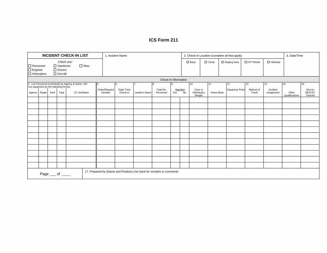
ICS Form 211
INCIDENT CHECK-IN LIST 1. Incident Name 2. Check-In Location (complete all that apply) 3. Date/Time
Check one: Personnel Handcrew Misc. Engines Dozers Helicopters Aircraft
Base
Camp
Staging Area
ICP Restat
Helibase
Check-In Information 4. List Personnel (overhead) by Agency & Name -OR- List equipment by the following format:
5. 6. 7. 8. 9. 10. 11. 12. 13. 14. 16. 16.
Agency
Single
Kind
Type
I.D. No/Name
Order/Request Number
Date/ Time Check-In
Leader’s Name
Total No. Personnel
Manifest Yes No
Crew or Individual’s
Weight
Home Base
Departure Point Method of Travel
Incident Assignment
Other
Qualifications
Sent to RESTAT Time/Int
Page ___ of ____ 17. Prepared by (Name and Position) Use back for remarks or comments


ICS 214
UNIT LOG 1. Incident Name
2. Date Prepared
3. Time Prepared
4. Unit Name/Designators
5. Unit Leader (Name and Position)
6. Operational Period
7. Personnel Roster Assigned Name ICS Position Home Base
8. Activity Log Time Major Events
9. Prepared by (Name and Position)


DEBRIEFING INFORMATION
Flight Plan Closed ATD ATA
Tach Start Tach End
Hobbs Start Hobbs To/From Hobbs in Area Hobbs Total Hobbs End
Fuel Used (Gal)
Oil Used (Qt) Fuel & Oil Cost Receipt # Wing Paid
Summary Results/Deliverables Weather Conditions Remarks Sortie Effectiveness Successful Marginal Unsuccessful Not Flown Not Required Reason (if not successful)
Weather Aircraft Maintenance Equipment Failure Crew Unavailable Customer Cancellation Other _____________________________
Attachments & Documentation AIF ORM Matrix AIF ARCHER Log CAPF 104a SAR Results Worksheet CAPF 104b Reconnaissance Summary ICSF 214 Unit Log Receipts Other _____________________________________________________________________
DEBRIEFING OFFICERS Phone
Debriefing Debriefer (Name & CAPID)
Time & Date Debriefed
CAP FORM 104, AUG 09 OPR/ROUTING: DO PAGE 4 OF 4 PAGES
MISSION FLIGHT PLAN/BRIEFING FORMTRACKING NUMBER
MISSION DATA SECTION Mission Number
Mission Name
Mission Symbol
Mission Date
MANIFEST, QUALIFICATIONS & AIRCRAFT DETAILS Pilot In Command (Name & CAPID)
MP TMP MFC WS COM IFR Night LES Trainee
Crew Member / Passenger 1 (Name & CAPID)
MCP MP TMP MFC COM IFR Night WS MO MS ADIS AP HRO LES Trainee Other
Crew Member / Passenger 2 (Name & CAPID)
MO MS ADIS AP HRO WS LES ARCHOPR ARCHTRK Trainee Other
Crew Member / Passenger 3 (Name & CAPID)
MO MS ADIS AP HRO WS LES ARCHOPR ARCHTRK Trainee Other
Crew Member / Passenger 4 (Name & CAPID)
MO MS ADIS AP HRO WS LES ARCHOPR ARCHTRK Trainee Other
Crew Member / Passenger 5 (Name & CAPID)
MO MS ADIS AP HRO WS LES ARCHOPR ARCHTRK Trainee Other
Crew Member / Passenger 6 (Name & CAPID)
MO MS ADIS AP HRO WS LES ARCHOPR ARCHTRK Trainee Other
Crew Member / Passenger 7 (Name & CAPID)
MO MS ADIS AP HRO WS LES ARCHOPR ARCHTRK Trainee Other
Crew Contact (Phone, E-mail, etc.) Tail Number
Callsign
Type
TAS (Knots) Color/Description CAP Member
Owned Fuel (In Hours) Home Base
Aircraft & Aircrew Equipment Transponder VOR DME Autopilot GPS_____________ CAP FM Radio Tactical Repeater Becker DF L-Tronics DF ARCHER Airborne System ARCHER Ground Station Digital Camera ADIS Satellite Phone _____________________ Survival Kit Life Raft & Vests Other ______________________
RELEASING OFFICERS Phone
Briefing
Briefer (Name & CAPID)
Flight Release Officer (Name & CAPID)
CAP FORM 104, AUG 09 OPR/ROUTING: DO PAGE 1 OF 4 PAGES PREVIOUS EDITIONS WILL NOT BE USED AFTER 30 SEP 09
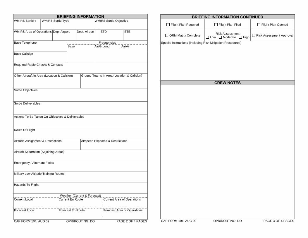
BRIEFING INFORMATION WMIRS Sortie #
WMIRS Sortie Type WMIRS Sortie Objective
WMIRS Area of Operations
Dep. Airport Dest. Airport ETD ETE
Base Telephone Frequencies
Base Air/Ground Air/Air
Base Callsign
Required Radio Checks & Contacts Other Aircraft in Area (Location & Callsign)
Ground Teams in Area (Location & Callsign)
Sortie Objectives Sortie Deliverables Actions To Be Taken On Objectives & Deliverables Route Of Flight Altitude Assignment & Restrictions
Airspeed Expected & Restrictions
Aircraft Separation (Adjoining Areas) Emergency / Alternate Fields Military Low Altitude Training Routes Hazards To Flight
Weather (Current & Forecast) Current Local Current En Route Current Area of Operations
Forecast Local
Forecast En Route Forecast Area of Operations
CAP FORM 104, AUG 09 OPR/ROUTING: DO PAGE 2 OF 4 PAGES
BRIEFING INFORMATION CONTINUED
Flight Plan Required Flight Plan Filed Flight Plan Opened
ORM Matrix Complete Risk Assessment Low Moderate High Risk Assessment Approval
Special Instructions (Including Risk Mitigation Procedures)
CREW NOTES CAP FORM 104, AUG 09 OPR/ROUTING: DO PAGE 3 OF 4 PAGES

INSTRUCTIONS FOR COMPLETION OF CAP FORM 104, AUG 09 GENERAL INFORMATION: This CAPF 104 has been designed to be printed on standard 8.5” by 11” paper, and folded in half so that crews can easily use them in the cockpit, attached to kneeboards. Crews will be able to complete them online in WMIRS and print out the form or save it in WMIRS as well. When using the online WMIRS version certain sections will only be available when appropriate. For example, crews will not be allowed to update briefing sections post flight. PAGE 1: TRACKING NUMBER: This will be automatically defaulted as the sortie number from WMIRS when using the WMIRS version, but can be replaced with a unique number determined by the mission staff when using WMIRS or the offline versions. MISSION DATA SECTION: This section will be automatically filled from WMIRS when using the WMIRS version, or can be manually filled offline. Details will be provided by the mission staff to fill this section appropriately offline. Sorties cannot be flown on multiple mission numbers, mission, names, or mission symbols. Though sorties could be flown over multiple dates, the data block provided will be filled with the starting date of the sortie. MANIFEST, QUALIFICATIONS, AND AIRCRAFT DETAILS: Most of this section is self explanatory. All crew members or passengers must be identified clearly. When using the WMIRS version, most data will be filled in automatically, and non-CAP passengers or crew members will be clearly identified so that a CAPF 9 can be completed when required, and to be sure appropriate authorizations have been received prior to flight release. The Mission Pilot will also have to be appropriately qualified in order to be slotted as such in the WMIRS version, but the mission staff will have to check this status by hand when working offline. Planners using the WMIRS version will be able to search for personnel that meet needed criteria for crew positions. The blocks are to be completed with the qualifications needed and a member must be selected that meets that criteria; the blocks are not meant to indicate all qualifications a member holds. Most aircraft information will be automatically completed based on prior entries in WMIRS and other NHQ databases, but can be updated on the form or in offline versions as necessary. The acronyms and abbreviations for crew qualifications are listed below for quick reference: ADIS = Aerial Digital Imaging System Operator AP = Airborne Photographer ARCHOPR = ARCHER Operator ARCHTRK = ARCHER Trac Technician COM = Commercial Pilot HRO = Highbird Radio Operator
IFR = Instrument Flight Rated Pilot LES = Law Enforcement Screened (CD Qual.) MCP = Mission Check Pilot MFC = Mountain Flying Certification MO = Mission Observer MP = Mission Pilot
MS = Mission Scanner Night = Pilot is current to fly at night TMP = Transport Mission Pilot WS = Water Survival
RELEASING OFFICERS: This section is used to record the personnel releasing the sortie, noting phone briefings for remote dispatch when necessary. The WMIRS version will only allow appropriately qualified personnel to be input into these fields. Within WMIRS, the briefer is required to be at least an AOBD trainee, and a qualified FRO must be listed for the FRO block; care must be taken when briefing crews offline that qualified personnel are used. Signatures are not required in these blocks. PAGE 2: BRIEFING INFORMATION: Though most information is self explanatory, details will likely vary from sortie to sortie. Where possible the data available will be automatically filled in the WMIRS version. The WMIRS version will also provide links and other tools in order to assist crews with selecting airports, determining weather, etc. Some of this data could be sensitive, and must be treated with appropriate handling procedures. Much of this data also focuses crew planning on potential safety issues, and must be carefully considered and planned. PAGE 3: BRIEFING INFORMATION CONTINUED: This section is used to track flight plan requirements for the crew, and risk management and assessment. Special instructions and measures required to mitigate identified risks are also documented in this section. CREW NOTES: This is mainly additional space for the crew to note any items that were not already covered in the briefing or that additional space was needed for, and also for crews to document key facts while in flight or for debriefers post flight. Within WMIRS crews will be able to make both text notes as well as attach pictures in this section. PAGE 4: DEBRIEFING INFORMATION: This section is used to note what actually happened during the sortie. Sorties are flown for intended purposes and objectives, and this section allows the debriefing officers to document if those properly as well as note issues for other crews with similar assignments in the future. Care should be taken to properly document what was accomplished; if results and success or failure are not properly documented then the sortie might as well not have been flown. When attachments or other documentation are necessary, they should be attached to this form by the crew and turned in to their debriefer. In order to facilitate total electronic processing of mission documentation in the future, this section will also have links to be able to link to or scan and attach documentation and attachments for the sortie as well. DEBRIEFING OFFICERS: This section is used to note who de-briefed the crew, when, and if it was done remotely over the phone. WMIRS will document completion automatically, and only allow personnel that are at least AOBD trainees or higher to be used as debriefers. Once the debriefing is listed as complete, data within the WMIRS version cannot be changed, but additions will be allowed after the fact, with dates and times annotated.


CREW REMARKS & NOTES CONTINUED Written Comments
CAP FORM 104a, AUG 09 OPR/ROUTING: DO PAGE 2 OF 2 PAGES
SAR RESULTS WORKSHEET TRACKING NUMBER
MISSION DATA SECTION Mission Number
Mission Date MO / MP / MS Reporting (Name & CAPID)
SEARCH AREA Name: Grid:
Corner Latitude Longitude Northwest
Northeast
Southwest
Southeast
SORTIE SEARCH PLAN VERSUS ACTUAL Variables Planned Actual
Search Pattern
Search Visibility (NM)
Search Altitude (AGL)
Search Speed (Knots)
Track Spacing (NM)
Terrain Flat Rolling Hills Rugged Hills Mountainous
Flat Rolling Hills Rugged Hills Mountainous
Cover Open Moderate Heavy Light Snow Heavy Snow
Open Moderate Heavy Light Snow Heavy Snow
Turbulence Light Moderate Heavy Light Moderate Heavy
Probability Of Detection
Time To Search Area
Time Started Search
Time Ended Search
Time In Search Area
Time From Search Area
Total Sortie Time
CREW REMARKS & NOTES Effectiveness: Excellent Good Fair Poor Score (1 to 5): Visibility: Excellent Good Fair Poor Score (1 to 5): CAP FORM 104a, AUG 09 OPR/ROUTING: DO PAGE 1 OF 2 PAGES

INSTRUCTIONS FOR COMPLETION OF CAP FORM 104a, AUG 09
GENERAL INFORMATION: This CAPF 104a has been designed to be printed on standard 8.5” by 11” paper, and folded in half so that crews can easily use them in the cockpit, attached to kneeboards. Crews will be able to complete them online in WMIRS and print out the form or save it in WMIRS as well. When using the online WMIRS version certain sections will only be available when appropriate. For example, crews will not be allowed to results to determine final PODs before the flight, only the plans. If a crew is assigned multiple search areas, multiple CAPF 104as can be attached to the CAPF 104. PAGE 1: TRACKING NUMBER: This will be automatically defaulted as the sortie number from WMIRS when using the WMIRS version, but can be replaced with a unique number determined by the mission staff when using WMIRS or the offline versions as well. If not using the default assigned in WMIRS in an offline version, mission staff officers need to be careful to match the tracking number with the appropriate sortie. If reporting online, the 104a will be tied to the primary sortie automatically when inputting data. MISSION DATA SECTION: This section will be automatically filled or be selectable from the WMIRS version, or can be manually filled offline. In the WMIRS version the data will be linked to the sortie being added and the primary 104, and you will only be able to select one of the crew members from the primary 104 as the member responsible for making the report. Details will need to be provided to the mission staff to fill this section appropriately offline. SEARCH AREA: Enter the name of the search area, the grid being searched, and the latitude and longitude of the corners of the search box so that the area that the crew is assigned to search is clearly identified. SORTIE SEARCH PLAN VERSUS ACTUAL: This section is used by the planning staff and the crew to lay out the search plan for the sortie based on the variables identified, and compare them to what was actually done post flight. Some variables factor into determining the probability of detection (POD) noted in grey below, while others don’t but impact how the search is conducted none the less.
OPEN FLAT TERRAIN MODERATE TREE COVER AND/OR HILLY
HEAVY TREE COVER AND/OR VERY HILLY
SEARCH VISIBILITY SEARCH VISIBILITY SEARCH VISIBILITY SEARCH ALTITUDE
TRACK SPACING 1 MILE 2 MILES 3 MILES 4 MILES 1 MILE 2 MILES 3 MILES 4 MILES 1 MILE 2 MILES 3 MILES 4 MILES .5 MILE 35% 60% 75% 75% 20% 35% 50% 50% 10% 20% 30% 30% 1 MILE 20% 35% 50% 50% 10% 20% 30% 30% 5% 10% 15% 15%
1.5 MILES 15% 25% 35% 40% 10% 15% 20% 20% 5% 5% 10% 10%
500 FT AGL
2 MILES 10% 20% 30% 30% 5% 10% 15% 15% 5% 5% 10% 10% .5 MILE 40% 60% 75% 80% 20% 35% 50% 55% 10% 20% 30% 35% 1 MILE 20% 35% 50% 55% 10% 20% 30% 35% 5% 10% 15% 20%
1.5 MILES 15% 25% 40% 40% 10% 15% 20% 25% 5% 5% 10% 15%
700 FT AGL
2 MILES 10% 20% 30% 35% 5% 10% 15% 20% 5% 5% 10% 10% .5 MILE 40% 65% 80% 85% 25% 40% 55% 60% 15% 20% 30% 35% 1 MILE 25% 40% 55% 60% 15% 20% 30% 35% 5% 10% 15% 20%
1.5 MILES 15% 30% 40% 45% 10% 15% 20% 25% 5% 10% 10% 15%
1000 FT AGL
2 MILES 15% 20% 30% 35% 5% 10% 15% 20% 5% 5% 10% 10% CREW REMARKS & NOTES: This is where the crew notes how effective they believe they were and what the visibility was in the search area. Though the effectiveness and visibility factors do not directly impact the mathematical formulas for determining the POD, these as well as written notes can assist search planners in determining if some areas need to be searched again. PAGES 2: CREW REMARKS & NOTES CONTINUED: The written comments block is where crews should clearly note remarks bearing on their results like if the mission observer had to assist heavily with radio communications rather than looking outside the aircraft, or if the mission scanner was not feeling well due to heavy turbulence. This section is also provided for the crew to makes notes or diagrams as necessary to successfully accomplish the mission.

IMAGERY / TARGET LOG CONTINUED Description Camera Photo #
Computer File Name Time
Photo / Target
#
15 Latitude
Longitude Direction Altitude
Description Camera Photo #
Computer File Name Time
Photo / Target
#
16 Latitude
Longitude Direction Altitude
Description Camera Photo #
Computer File Name Time
Photo / Target
#
17 Latitude
Longitude Direction Altitude
Description Camera Photo #
Computer File Name Time
Photo / Target
#
18 Latitude
Longitude Direction Altitude
Description Camera Photo #
Computer File Name Time
Photo / Target
#
19 Latitude
Longitude Direction Altitude
Description Camera Photo #
Computer File Name Time
Photo / Target
#
20 Latitude
Longitude Direction Altitude
Description Camera Photo #
Computer File Name Time
Photo / Target
#
21 Latitude
Longitude Direction Altitude
CAP FORM 104b, AUG 09 OPR/ROUTING: DO PAGE 4 OF 4 PAGES
RECONNAISSANCE SUMMARY TRACKING NUMBER
MISSION DATA SECTION Mission Number
Mission Date ADIS / AP / MO / MS Reporting (Name & CAPID)
TARGETS & REQUIREMENTS CAP FORM 104b, AUG 09 OPR/ROUTING: DO PAGE 1 OF 4 PAGES
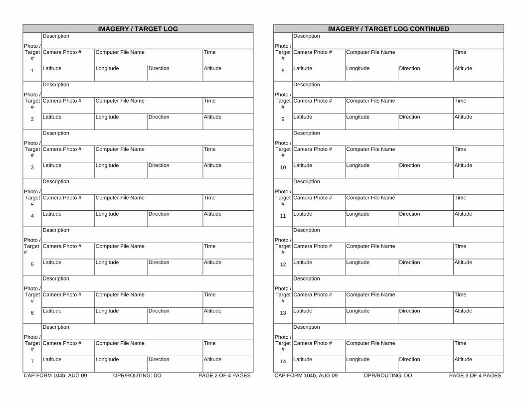
IMAGERY / TARGET LOG Description Camera Photo #
Computer File Name Time
Photo / Target
#
1 Latitude
Longitude Direction Altitude
Description Camera Photo #
Computer File Name Time
Photo / Target
#
2 Latitude
Longitude Direction Altitude
Description Camera Photo #
Computer File Name Time
Photo / Target
#
3 Latitude
Longitude Direction Altitude
Description Camera Photo #
Computer File Name Time
Photo / Target
#
4 Latitude
Longitude Direction Altitude
Description Camera Photo #
Computer File Name Time
Photo / Target #
5 Latitude
Longitude Direction Altitude
Description Camera Photo #
Computer File Name Time
Photo / Target
#
6 Latitude
Longitude Direction Altitude
Description Camera Photo #
Computer File Name Time
Photo / Target
#
7 Latitude
Longitude Direction Altitude
CAP FORM 104b, AUG 09 OPR/ROUTING: DO PAGE 2 OF 4 PAGES
IMAGERY / TARGET LOG CONTINUED Description Camera Photo #
Computer File Name Time
Photo / Target
#
8 Latitude
Longitude Direction Altitude
Description Camera Photo #
Computer File Name Time
Photo / Target
#
9 Latitude
Longitude Direction Altitude
Description Camera Photo #
Computer File Name Time
Photo / Target
#
10 Latitude
Longitude Direction Altitude
Description Camera Photo #
Computer File Name Time
Photo / Target
#
11 Latitude
Longitude Direction Altitude
Description Camera Photo #
Computer File Name Time
Photo / Target
#
12 Latitude
Longitude Direction Altitude
Description Camera Photo #
Computer File Name Time
Photo / Target
#
13 Latitude
Longitude Direction Altitude
Description Camera Photo #
Computer File Name Time
Photo / Target
#
14 Latitude
Longitude Direction Altitude
CAP FORM 104b, AUG 09 OPR/ROUTING: DO PAGE 3 OF 4 PAGES

INSTRUCTIONS FOR COMPLETION OF CAP FORM 104b, AUG 09 GENERAL INFORMATION: This CAPF 104b has been designed to be printed on standard 8.5” by 11” paper, and folded in half so that crews can easily use them in the cockpit, attached to kneeboards. Crews will be able to complete them online in WMIRS and print out the form or save it in WMIRS as well. When using the online WMIRS version certain sections will only be available when appropriate. For example, crews will not be allowed to update the imagery log before the flight. PAGE 1: TRACKING NUMBER: This will be automatically defaulted as the sortie number from WMIRS when using the WMIRS version, but can be replaced with a unique number determined by the mission staff when using WMIRS or the offline versions as well. If not using the default assigned in WMIRS in an offline version, mission staff officers need to be careful to match the tracking number with the appropriate sortie. If reporting online, the 104b will be tied to the primary sortie automatically when inputting data. MISSION DATA SECTION: This section will be automatically filled or be selectable from the WMIRS version, or can be manually filled offline. In the WMIRS version the data will be linked to the sortie being added and the primary 104, and the crew will only need to select one of the crew members from the primary 104 as the member responsible for making the report. Details will need to be provided to the mission staff to fill this section appropriately offline. TARGETS & REQUIREMENTS: This section is to be used by the crew member responsible to note any imagery or other reconnaissance requirements for the sortie. For example, the member may be asked to take photos from the four cardinal points of a specific building from a specific altitude, or they could be flying a law enforcement support mission noting the geographic location of potential locations of illegal activity. PAGES 2 - 4: IMAGERY / TARGET LOG: Though most information is self explanatory, details will likely vary from sortie to sortie based on the customer request. Crew members must document imagery and/or targets accurately. The time a picture is taken, latitude, longitude and altitude (MSL) where it is taken from, and the direction that photos are taken can be crucial to analysts reviewing photos after the flight. Using the log to document sightings by the naked eye of crew members can also be critical; simply transposing a digit in a latitude or longitude can cause personnel on the ground to waste significant time and possibly not find the target. Crews will also be able to upload imagery from this section to WMIRS when online. It is not necessary to log every photo taken; rather this section should be used to log information for critical photos to meet the requirements.

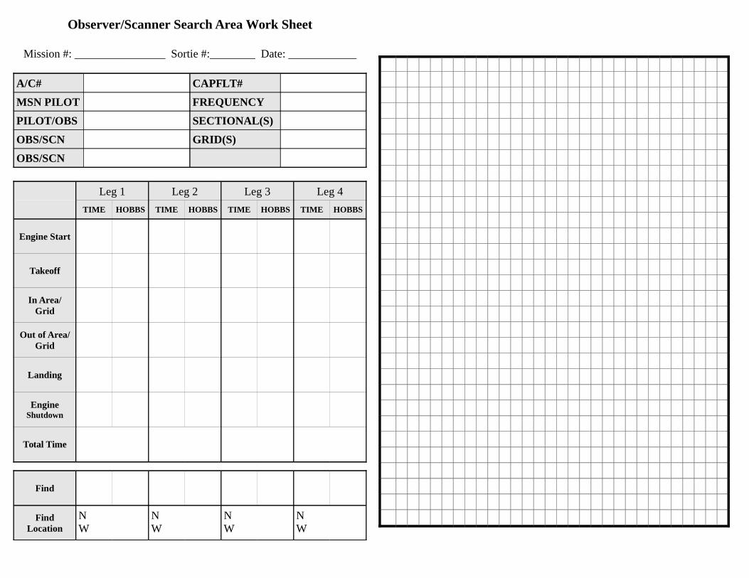
Observer/Scanner Search Area Work Sheet
Mission #: ________________ Sortie #:________ Date: ____________
A/C# CAPFLT#
MSN PILOT FREQUENCY
PILOT/OBS SECTIONAL(S)
OBS/SCN GRID(S)
OBS/SCN
Leg 1 Leg 2 Leg 3 Leg 4
TIME HOBBS TIME HOBBS TIME HOBBS TIME HOBBS
Engine Start
Takeoff
In Area/Grid
Out of Area/Grid
Landing
EngineShutdown
Total Time
Find
FindLocation
NW
NW
NW
NW


“High Bird” Transmission and Roll Call Log
Mission #: _________________ Sortie #:_________ Date: __________________
TMP / MP N-Number
MO / MRO CAPFLT #
MS / MRO Channel
MS / MRO Channel
TimeCallsign
MessageFrom To
Latitude Longitude Status
Latitude Longitude Status
Latitude Longitude Status
Latitude Longitude Status
Latitude Longitude Status
Latitude Longitude Status
Latitude Longitude Status
Latitude Longitude Status
Latitude Longitude Status
Latitude Longitude Status
Latitude Longitude Status
Latitude Longitude Status
Latitude Longitude Status
Latitude Longitude Status
Latitude Longitude Status
Latitude Longitude Status
Latitude Longitude Status
Latitude Longitude Status
Latitude Longitude Status
Latitude Longitude Status
Latitude Longitude Status
SPCS Form 110A(60) Sheet ____ of ____ Page 1
TimeCallsign
MessageFrom To
Latitude Longitude Status
Latitude Longitude Status
Latitude Longitude Status
Latitude Longitude Status
Latitude Longitude Status
Latitude Longitude Status
Latitude Longitude Status
Latitude Longitude Status
Latitude Longitude Status
Latitude Longitude Status
Latitude Longitude Status
Latitude Longitude Status
Latitude Longitude Status
Latitude Longitude Status
Latitude Longitude Status
Latitude Longitude Status
Latitude Longitude Status
Latitude Longitude Status
Latitude Longitude Status
Latitude Longitude Status
Latitude Longitude Status
Latitude Longitude Status
Latitude Longitude Status
Latitude Longitude Status
Latitude Longitude Status
Latitude Longitude Status
Latitude Longitude Status
Page 2
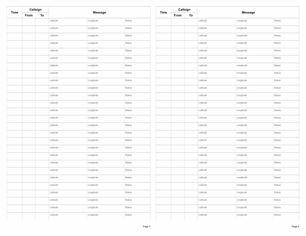
TimeCallsign
MessageFrom To
Latitude Longitude Status
Latitude Longitude Status
Latitude Longitude Status
Latitude Longitude Status
Latitude Longitude Status
Latitude Longitude Status
Latitude Longitude Status
Latitude Longitude Status
Latitude Longitude Status
Latitude Longitude Status
Latitude Longitude Status
Latitude Longitude Status
Latitude Longitude Status
Latitude Longitude Status
Latitude Longitude Status
Latitude Longitude Status
Latitude Longitude Status
Latitude Longitude Status
Latitude Longitude Status
Latitude Longitude Status
Latitude Longitude Status
Latitude Longitude Status
Latitude Longitude Status
Latitude Longitude Status
Latitude Longitude Status
Latitude Longitude Status
Latitude Longitude Status
Page 3
TimeCallsign
MessageFrom To
Latitude Longitude Status
Latitude Longitude Status
Latitude Longitude Status
Latitude Longitude Status
Latitude Longitude Status
Latitude Longitude Status
Latitude Longitude Status
Latitude Longitude Status
Latitude Longitude Status
Latitude Longitude Status
Latitude Longitude Status
Latitude Longitude Status
Latitude Longitude Status
Latitude Longitude Status
Latitude Longitude Status
Latitude Longitude Status
Latitude Longitude Status
Latitude Longitude Status
Latitude Longitude Status
Latitude Longitude Status
Latitude Longitude Status
Latitude Longitude Status
Latitude Longitude Status
Latitude Longitude Status
Latitude Longitude Status
Latitude Longitude Status
Latitude Longitude Status
Page 4
MISSION REGISTRATION (Be prepared to show CAP ID card, driver’s licenses, 101 card when turning in this form.)
Date:
Personal InformationLast Name: First Name: Rank: CAP ID: Unit # (REG-WG-UNIT):
CAP Drivers License: Exp: State Drivers License: Exp:
Pilot License: Exp: Telephone Num: Age (cadet only):
CAPF 60 Yes No Member will be sent to Logistics Base (OOS) until information can be verified in WMU, Staple copy of form 60 to this form.
I PLAN TO FILE FOR REIMBURSEMENT
Qualification Information
CAPF 101 Yes No (RUL will verify qualifications on 101 card. Make sure date for each qualification is current. Place T after qualification if member is in training for qualification)
Incident Commander Mission Chaplain Ground Team Member Agency Liaison Air Branch Director UDF Member Finance/ Admin Section Chief Ground Branch Director Flight Line Supervisor Planning Section Chief Communications Unit Leader Flight Line Member Logistics Section Chief SAR/DR Mission Pilot Mission Radio Operator Operations Section Chief Mission Observer Mission Staff Assistant Liason Officer Mission Scanner GES ONLY Mission Safety Officer Ground Team Leader
For GTL or Mission Pilots only: Are you member of a complete air crew or ground team for this mission?(Even if you and your team are preassigned for other duties we need this for resource management)
Yes No
Other names of air crew / team members (First Initial/Last name): 1. 2. 3. 4. 5.
Status (This section completed by Resource Unit Leader at mission)
OOS Logistics Base Off Base Home
Available OPS Staging Area: Ground Air RUL Staging area:
Assigned Staff (position) A/C GT
Previous assignments this mission
Duty Start Time: Duty End Time: (For Aircrews the time left or returned to quarters to start/end the day, for all others time put on available status)
Resource Unit Leader Initials:IlWG Form 605, May 2009 PREVIOUS EDITIONS ARE OBSOLETE OPR:ILWG/DO