Embed Size (px)
Citation preview
c
\
MISSION
I
FOR WTR LAUNCHES r
.
GPO PRICE $
CFSTl PRICE(S) $
Hard copy (HC) # 3 / 0 0 ; , .
. I .
Microfiche (MF) 136 ff 853 July 65
AUGUST 1966
* - I-
1 ,
I .
- m i GODDARD SPACE FtlfiHT CENTER - GREENBELT, MARYLAND .
- . b r(
863
< I
https://ntrs.nasa.gov/search.jsp?R=19660025573 2018-08-10T16:03:11+00:00Z
u) L
c
TOS MISSION OPERATIONS PLAN
FOR WTR LAUNCHES
A. D. Rossi T&DS Representative
August 1966
Approved by :
L' W. W. Jones
TOS Project Manager
COORDINATION
E. G. Albert ESSA Representative
c .
a
Memo for: Distribution
This is the TOS Mission Operations Plan for WTR launches.
Please remove the original TOS Mission Operations Plan from the binder and
discard it except for: (1) the index tabs, (2) Figure IJI-6, Subsatellite Track,
page III-20, which are to be used for the WTR Mission Operations Plan.
A completely revised Mission Operations Plan will be issued for ETR launches.
Any changes or additions to this plan should be directed to the attention of the
TOS Project Manager.
i
ORBIT
n
z
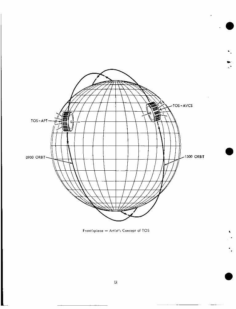
Frontispiece - Artist's Concept of TOS
ii
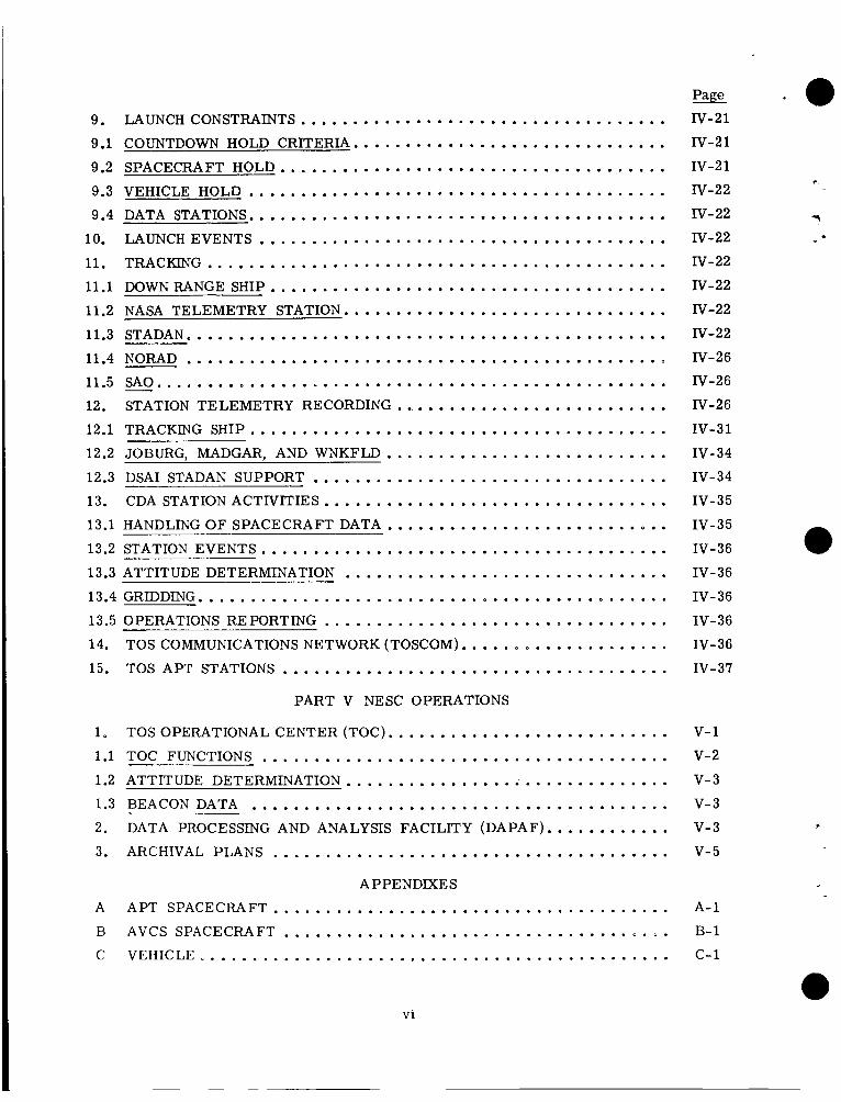
CONTENTS
.G .
PART I TOS PROGRAM SUMMARY
PART 11 TOS SYSTEM OPERATIONAL PLAN
1 . TOC AND TEC RESPGPU'SIB1Ll"ES Ah9 COORDXXATION ............. 1.1 TOC RESPONSIBILITIES ................................... 1.2 TECRESPONSIBIUTIES. ..................................
1.2.1 PRELAUNCH OPERATIONS .......................... 1.2.2 LAUNCH. INITLAL MANEUVER. AND CHECKOUT ............
1.3 TOC/TEC COORDINATION AND REPORTS ....................... 1.3.1 1.3.2
CONFLICTS DURING LAUNCH AND CHECKOUT ............. REPORTS AND OTHER COORDINATION ACTMTIES ..........
2 . CDA-TEC-TOC MISSION SIMULATION EXERCISE ................. 2.1 WALOMS SCHEDULE ..................................... 2.2 GILMORSCHEDULE ...................................... 3 . FIVE-DAY ACTIVATION PLAN .............................. 4 . COORDINATEDREADINESS ................................. 5 . T&DS MISSION SIMULATION TEST ............................
PART III GSFC OPERATIONS
1 . TEC ................................................. 1.1 SYSTEMS OPERATIONS - LAUNCH AND CHECKOUT PLAN ...........
1.1.1 REALTIME SYSTEMS ASSESSMENT AND EVALUATION ........ 1.1.1.1 Prepass Functions .................................
1
.
1.1.1.2 Functions During a Pass ............................. 1.1.1.3 Postpass Functions ................................. 1.1.1.4 Engineering Data .................................. 1.1.2 NEAR-REAL-TIME SYSTEMS EVALUATION ............... 1.1.3 MANUAL ATTITUDE DETERMINATION ................... 1.1.3.1 Prepass Functions ................................. 1.1.3.2 Function During a Pass .............................. 1.1.3.3 Postpass Functions .................................
TEC EQUIPMENT OPERATION. CALIBRATION. AND MAINTE- NANCE ........................................
1.1.4.1 Communications Lines .............................. 1.1.4
1.1.4.2 Logs .......................................... 1.1.5 OPERATIONAL PROCEDURES ........................ -
Page
I- 1
.
II- 1
11-1
11-1
11-2 11-2
11-2
11-4
11-4
II- 4
11-5
11-5
11-5
11-6 11-6 II- 6
m- 1
m-2
m- 2
111-2
m-2
m-2 III- 3
111-4
m- 5
m-5
111- 5 m- 5
m- 5
m- 5 m-7 III- 8
iii
Page . 1.1.5.1 Prepass Operations ................................ 111-8
.
1.1.5.2 Operation During a Pass ............................. 111-8
1.1.5.3 Postpass Operation ................................ 111-9 1.1.5.4 APT Operation ................................... 111-9
1.2
1.3
1.4
1.5 2 . 2.1
2.2
3 . 3.1
3.2
1.1.5.5 AVCS Video operation .............................. 1.1.6 RESPONSIBILITIES ................................ SCHEDULING AND PROGRAMMING - LAUNCH AND CHECKOUT PHASE . . 1.2.1 PLANNED OPERATIONS SCHEDULE .................... 1.2.2 DAILYSCHEDULE ................................. 1.2.3 SPACECRAFT PROGRAMMING ........................ 1.2.4 SCHEDULING AND PROGRAMMING REQUIREMENTS ......... ENGINEERING DOCUMENTATION AND REPORTING ............... COMMUNICATIONS AND DATA TRANSMISSION ................... 1.4.1 CDA STATION STATUS .............................. 1.4.2 DATA TRANSMISSION .............................. 1.4.3 DATA PROVIDED TO TOC ........................... GRAPHICDISPLAYS ..................................... ORBIT AND ATTITUDE DETERMINATION ...................... DSDPRELAUNCHSUPPORT ................................ 2.1.1 2.1.2
ORBIT ANALYSIS AND SYSTEM READINESS
AUTOMATIC ATTITUDE DETERMINATION PROGRAM SYSTEM (AADPS) ........................................
2.1.3 DSD PRELAUNCH SCHEDULE ......................... EARLY ORBIT AND ATTITUDE DETERMINATION PLAN . . . . . . . . . . . . . 2.2.1 ORBIT ......................................... 2.2.2 ATTITUDE ...................................... GSFCOPERATIONSCONTROL .............................. OPSCON ............................................. MISSIONCONTROLROOM .................................
...............
111-9
111- 9
111- 10
111- 1 0
111- 10
111- 11
111- 1 1
111- 12
111- 12
m-12 111-12 111-12
111- 12
111- 13
111- 14
111- 14
111- 14
111- 15
111- 15 111-15
111-20
m-21
m-21
111-22
3.3 TELEPHONE COMMUNICATIONS ............................. 111-22
3.4 DISPLAYS ............................................ m-22
3.4.1 STATION STATUS ................................. III-23
3.4.2 LAUNCH EVENTS AND ORBITAL ELEMENTS .............. 111-23
3.4.3 DOPPLER PLOT .................................. 111-23
3.4.4 MESSAGE DISPLAY ................................ 111-23
3.4.5 FLIGHT PATH ANGLE VERSUS VELOCITY RATIO ........... III-23
iv
3
ir .
R
3.4.6 SUBSATELLITE PLOT .............................. 3.4.7 COUNTDOWN CLOCK .............................. 3.4.8 GMTCLOCK ..................................... 3.4.9 PROJECTION SCREEN .............................. 3.4.10 TRACKING AND TELEMETRY SCHEDULE ................ 3.5 TELEVISION .....................................
PART IV FIELD OPERATIONS .# T T T n 1 . u u u A?.m TOS PRC?.mCT .................................. 2 . WTR FACILITIES ....................................... 3 . WTR ORGANIZATION .................................... 3.1 NASA RANGE SUPPORT .................................. 3.2 RANGEOPERATIONSBRANCH .............................. 3.3 DELTA OPERATIONS BRANCH .............................. 3.4 VEHICLE AND SPACECRAFT SUPPORT BRANCH ................. 4 . TOSPROJECTATWTR ................................... 4.1 NnSSIONDIRECTOR ..................................... 4.2 ASSISTANT MISSION DIRECTOR ............................. 4.3 OPERATIONS AND LAUNCH D m C T O R ........................ 4.4 MISSION OPERATIONS MANAGER (KSC/ULO) .................... 4.5 TEST CONTROLLER (KSC/ULO) ............................. 4.6 TESTCONDUCTOR(DAC) .................................. 4.7 SPACECRAFT COORDINATOR (KSC/ULO) ...................... 4.8 SPACECRAFT SYSTEMS MANAGER ........................... 5 . LAUNCH COMMUNICATIONS ............................... 5.1 WTR RANGE COMMUNICATIONS ............................. 5.2 SCAMA .............................................. 5.3 NASA COMMUNICATIONS RULES AND COUNTDOWN ............... 6 . SPACECRAFT AND VEHICLE COUNTDOWN ..................... 7 . VEHICLEHANDLING ..................................... 8 . SPACECRAFT HANDLING ................................. 8.1 SHIPMENT O F SPACECRAFT AND SUPPORT EQUIPMENT ........... 8.2 SPACECRAFT HANDLING AT BUILDING 34 ..................... 8.3 SEPET AND INTERFERENCE TESTS .......................... 8.4 SPIN TEST FACILITY .................................... 8.5 SERVICETOWER ....................................... 8.6 S U M M Y OF WTR OPERATIONS SCHEDULE ....................
Page
III- 23
III-23
III-23
IlI-23
IlI-24
1d-24
.
IV- 1 IV- 1
1v-8
IV- 8
IV- 8
1v-8
IV- 8
IV- 8
IV- 8
rv-10
N - 1 0
1v-10 nr-10
1v-11 1v-11
1v-11 1v-11 1v-11 1v-11 1v-11 1v-14
1v-14 iv-14 1v-14 1v-14 1v-19 1v-19 IV- 19
1v-20
V
- a 9 . LAUNCHCONSTRAINTS ................................... 9.1 COUNTDOWN HOLD CRITERIA .............................. 9.2 SPACECRAFT HOLD ..................................... 9.3 VEHICLE HOLD ........................................ 9.4 DATA STATIONS ........................................
10 . LAUNCHEVENTS ....................................... 11 . TRACKING ............................................ 11.1 DOWN RANGE SHIP ...................................... 11.2 NASA TELEMETRY STATION ............................... 11.3 STADAN .............................................. 11.4 NORAD .............................................. 11.5 SA0 ................................................. 12 . STATION TELEMETRY RECORDING .......................... 12.1 TRACKING SHIP ........................................ -
12.2 JOBURG. MADGAR. AND WNKFLD ........................... 12.3 DSAI STADAN SUPPORT .................................. 13 . CDA STATION ACTIVITIES ................................. 13.1 HANDLING OF SPACECRAFT DATA ........................... 13.2 STATION EVENTS ....................................... 13.3 ATTITUDE DETERMINATION ............................... 13.4 GRIDDING ............................................. 13.5 OPERATIONS REPORTING ................................. 14 . TOS COMMUNICATIONS NETWORK (TOSCOM) .................... 15 . TOS APT STATIONS .....................................
PART V NESC OPERATIONS
1 . TOS OPERATIONAL CENTER (TOC) ........................... 1.1 TOC FUNCTIONS ....................................... 1.2 ATTITUDE DETERMINATION ............................... 1.3 BEACON DATA ........................................ 2 . DATA PROCESSING AND ANALYSIS FACILITY (DAPAF) ............ 3 . ARCHIVAL PLANS ......................................
APPENDIXES
A APT SPACECRAFT ...................................... B AVCS SPACECRAFT ..................................... C VEHICLE .............................................
Page iv-21 iv-21
iv-21
1v-22
1v-22 1v-22
1v-22
1v-22 1v-22
1v-22
1v-26 1v-26 1v-26
1v-31
1v-34
1v-34
IV- 35
1v-35
1v-36
1v-36
1v-36
1v-36
1v-36
1v-37
v- 1
v- 2
v- 3
v- 3
v- 3
v- 5
r .
?
A- 1
B- 1
c- 1
vi
. a -
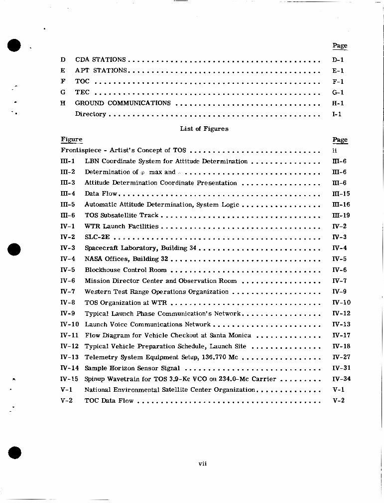
D CDASTATIONS ......................................... E APT STATIONS ......................................... F TOC ................................................ G TEC ................................................ H GROUND COMMUNICATIONS ...............................
Directory ............................................. List of Figures
Firrure Frontispiece . Artist's Concept of TOS ............................ 111-1 LBN Coordinate System for Attitude Determination ............... 111-2 Determination of 5 max and ............................. III-3 Attitude Determination Coordinate Presentation ................. 111-4 DataFlow ........................................... 111-5 Automatic Attitude Determination. System Logic ................. 111-6 TOS Subsatellite Track .................................. IV-1 WTFZ Launch Facilities .................................. IV-2 SLC-LE ............................................ IV-3 Spacecraft Laboratory. Building 34 .......................... IV-4 NASA Offices. Building 32 ................................ IV-5 Blockhouse Control Room ................................ IV-6 Mission Director Center and Observation Room ................. IV-7 Western Test Range Operations Organization ................... IV-8 TOS Organization at WTR ................................ IV-9 Typical Launch Phase Communication's Network ................. IV-10 Launch Voice Communications Network ....................... IV-11 Flow Diagram for Vehicle Checkout at Santa Monica .............. IV-12 Typical Vehicle Preparation Schedule. Launch Site ...............
Telemetry System Equipment Setup. 136.770 MC ................. IV-14 Sample Horizon Sensor Signal .............................
Spinup Wavetrain for TOS 3.9-Kc VCO on 234.0-Mc Carrier ......... National Environmental Satellite Center Organization ..............
IV-13
IV-15
V- 1
V-2 TOCDataFlow .......................................
D- 1
E- 1
F- 1
G- 1 H- 1
I- 1
page ii
m - 6
m- 6
111-6
III-15
Itl-16
m- 19
1v-2 IV- 3
1v-4
nr- 5
IV- 6
IV- 7 1v-9 1v-10 1v-12
1v-13
1v-17
1v-18
1v-27 1v-31 iv-34 v- 1
v- 2
vii
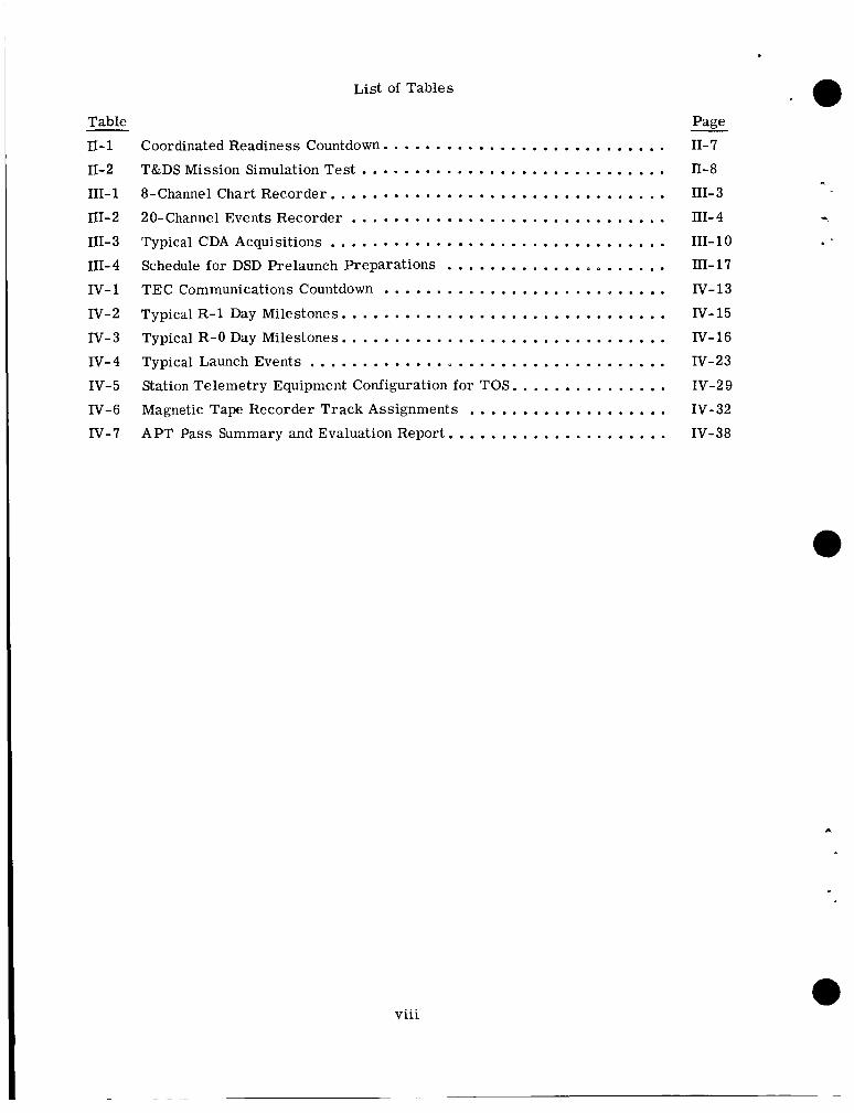
List of Tables
Table
11- 1
11-2
111- 1 III- 2
111- 3
111- 4
IV- 1
IV-2
IV- 3
IV- 4
IV- 5
IV-6 IV-7
Coordinated Readiness Countdown ........................... T&DS Mission Simulation Test ............................. 8-Channel Chart Recorder ................................ 20-Channel Events Recorder .............................. Typical CDA Acquisitions ................................ Schedule for DSD Prelaunch Preparations
TEC Communications Countdown ........................... Typical R-1 Day Milestones ............................... Typical R-0 Day Milestones ............................... Typical Launch Events .................................. Station Telemetry Equipment Configuration for TOS ............... Magnetic Tape Recorder Track Assignments
APT Pass Summary and Evaluation Report .....................
.....................
...................
viii
Pane . 11-7
11-8 111- 3 111- 4
111- 10
111-17 1v-13 IV- 15
1v-16 1v-23 1v-2 9
1v-32 1v-38
.
c
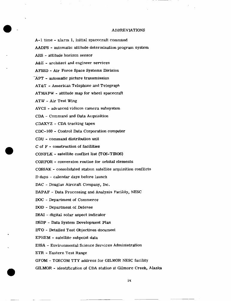
ABBREVIATIONS
A-1 time - alarm 1, initial spacecraft command
AADPS - automatic attitude determination program system
AHS - attitude horizon sensor
A&E - archikect aid e r a n e e r services
AFSSD - Air Force Space Systems Division
APT - automatic picture transmission
AT@i - AmeriCai Te’reghone znc! TeIegxqh
ATMAPW - attitude map for wheel spacecraft
ATW - Air Test Wing
AVCS - advanced vidicon camera subsystem
CDA - Command and Data Acquisition
CDAXYZ - CDA tracking tapes
CDC-160 - Control Data Corporation computer
CDU - command distribution unit
C of F - construction of fxilities
CONFLK - satellite conflict list (TOS-TIRW)
CORMlR - conversion routine for orbital elements
COSSAK - consolidated station satellite acquisition conflicts
D days - calendar days before launch
DAC - Douglas Aircraft Company, Inc.
DAPAF - Data Processing and Analysis Facility, NESC
DOC - Department of Commerce
DOD - Department of Defense
DSAI - digital solar aspect indicator
DSDP - Data System Development Plan
DTO - Detailed Test Objectives document
EPHEM - satellite subpoint data
ESSA - Environmental Science Services Administration
ETR - Eastern Test Range
GFOM - TOSCOM TTY address for GILMOR NESC facility
/
GILMOR - identification of CDA station at Gilmore Creek, Alaska
ix
GHNJ - RCA-AED TTY address
GMOR - NASCOM TTY address for GILMOR
GMT - Greenwich Mean Time, also Zulu or UT
GOFF - TOSCOM TTY address for Offutt
GOPS - OPSCON TTY address
GOSI - TTY address for TIROS/TEC
GNET - NETCON TTY address
GPUT - GSFC computer TTY address
GSFC Goddard Space Flight Center
GTEC - TOSCOM TTY address for TEC
GTOS - NASCOM TTY address for TOC
HCI - horizon crossing indicator
IRFNA - inhibited red fuming nitric acid
IRIG - interrange instrumentation group
KSC - Kennedy Space Center
LATOC - satellite look angles (antenna pointing angles)
LOS - loss of signal
MDC - Mission Director Center, WTR
MCR - Mission Control Room, GSFC
M&O - maintenance and operation
MASC - magnetic attitude spin coil
MBC - magnetic bias coil
MECO - main engine cutoff
MGAPW-ASP - magnetic attitude prediction, wheel - attitude smoothing program
MIG - miniature integrating gyro
NASA - National Aeronautics and Space Administration
NASCOM - NASA communications network
NASCOP - NASA communications operating procedures
NE&O - Network Engineering and Operations Division, GSFC
NESC - National Environmental Satellite Center, Suitland, Md.
NETCON - Network Control, GSFC
NORAD - North Atlantic Air Defense Command
X
NWRC - National Weather Records Center, Asheville, N.C.
OFFUTT - Offutt Air Force Base, Neb., station identification
OIS - Operational Intercom System, ETR
OPSCON - operations control, GSFC
OS0 - Operational Satellites Office, GSFC
PDP - Project Development Plan
PMP - Program Management Plan
POP - Program Obligation Plan
PRD - Program Requirements Document
QOMAC - quarter-orbit magnetic attitude control
R&D - research and development
RCA-AED - Radio Corporation of America, Astro Electronics Division
RCAZEINJ - identification of RCA CDA and APT station
RCAS - RCA Service Company
SA0 - Smithsonian Astrophysical Observatory
SCAMA - switching, conferencing, and monitoring arrangement
SECO - sustainer engine cutoff
SS&SA - Space Sciences and Satellite Applications
SSOD - TTY address for NESC Operations Division
STADAN - Space Tracking and Data-Acquisition Network
STADEE - status data extraction evaluation and reduction
STOC - TTY address for TOC
T&DS - Tracking and Data Systems Directorate, GSFC
TAD - thrust-augmented Delta
TAT - thrust-augmented Thor
TEC - TOS Evaluation Center, GSFC
TID - Technical Information Division, GSFC
TIROS - Television Infrared Observation Satellite
TOC - TOS Operational Center, NESC
TOS - Tiros Operational System
TOSCOM - TOS communications network, operated by NESC
TTCC - TIROS Technical Control Center, GSFC
xi
TTY - teletype
UDMH - unsyinmetrical dimethyl-hydrazine
ULASKA - NASA R&D station at Gilmore Creek, used as GILMOR backup
ULO - Unmanned Launch Operations
UT - Universal Time, GMT
VAFB - Vandenberg Air Force Base
WALOMS - identification of Wallops Station, Va., NESC facility
WOMS - TOSCOM TTY address for WALOMS
WMO - World Meteorological Organization
WMSAD - world map and station acquisition data
WTR - Western Test Range
ZULU - Greenwich Mean Time o r UT
xi i
PART I
TOS PROGRAM SUMMARY
The TIROS Operational System (TOS) is a joint effort of NASA and the Environmental Science Services Administration (ESSA). NASA's Goddard Space Flight Center (GSFC) is responsible for design and development of the spacecraft, vehicle, and ground systems, for launch operations, for initial spacecraft checkor;t in orbit, for spacecraft evaluatiop, and for interferometer tracking. ESSA is responsible for the operational phase of each space- craft, including determination of need for replacement; for operation of the CDA stations and ESSA communication lines; and for acquiring, handling, and processing spacecraft- acquired data. ESSA is responsible for all funding and for overall system evaluation and management . This Mission Operations Plan describes the execution of NASA responsibilities and the necessary interfaces with ESSA. The ESSA plan for its TOS activities will be published separately by ESSA.
To meet ESSA's requirements for obtaining meteorological data from the entire globe on a daily basis, TOS will have two operational spacecraft in circular 750-nm sun-synchron- ous, near-polar orbits, with launches at intervals of approximately 3 months. The orbit will be 78.84 degrees retrograde with an orbital period of 113.5 minutes. The spacecraft will be spin-stabilized and magnetically torqued to a wheel attitude, so that the spin axis will be normal to the plane of the orbit and the radially mounted cameras will view the earth once each spacecraft revolution. The orbital plane will precess easterly about 1 degree a day at the same rate as the earth-sun line.
The first TOS spacecraft, weighing about 285 lbs., carried two automatic picture trans- mission (APT) cameras and was launched on February 28, 1966, into an 0900 hour (de- scending node) orbit. The second spacecraft, weighing about 316 lbs., will have two advanced vidicon camera systems (AVCS) and an infrared (IR) system and will be launched into a 1500 hour (ascending node) orbit. The 750-nm altitude allows full global coverage with one camera; therefore, two cameras provide full system redundancy.
The first launch was from the Eastern Test Range (ETR); the second and following launches will be from the Western Test Range (WTR). The launch vehicle is the Im- proved Delta, DSV-3E.
Based conservatively upon the average lifetime of the TIROS spacecraft, the life expec- tancy of TOS spacecraft is 6 months, with a minimum of 3 months. Therefore, alternate configurations of the TOS spacecraft (APT, AVCS, APT, AVCS) will be made available by the contractor every 3 months. The objective, however, is to launch a replacement spacecraft within approximately a month after ESSA's decision to launch.
The spacecraft will be commanded and meteorological and spacecraft data will be acquired by Command and Data Acquisition (CDA) stations in Fairbanks, Alaska (GILMOR), and Wallops Station, Va. (WALOMS). The combination of WALOMS and GILMOR provides complete global coverage each day. All spacecraft data will be sent by data link and tele- type to ESSA's National Environmental Satellite Center (NESC) at Suitland, Md., for engineering evaluation and for analysis and dissemination of meteorological data to the meteorological community. Data will also be sent to GSFC for spacecraft checkout and evaluation. Meteorological data, spacecraft attitude data, and time will be transmitted to the Global Weather Center, Offutt A i r Force Base, Omaha, Neb.
I- 1
The spacecraft will be tracked by the NASA Space Tracking and Data Acquisition Net- work (STADAN) operated by GSFC Network and Engineering (NE&O) Division. Tracking information will be used by the GSFC Data Systems Division (DSD) for orbital determina- tion during the early orbit phase and for orbital refinement; orbital data will be sent to STADAN via the NASA Communications (NASCOM) facilities.
1-2
, - a
&acecraft Characteristics
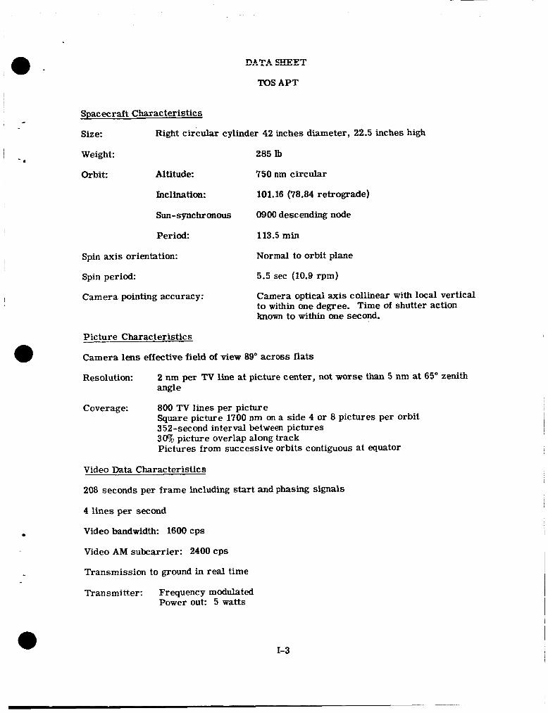
Size: Right circular cylinder 42 inches diameter, 22.5 inches high
Weight: 285 Ib
Orbit: Altitude: 750 nm circular
InclinatiOn: 101.16 (78.84 retrograde)
Sun-synchronous 0900 descending node
Period: 113.5 min
Spin axis orientation:
Spin period:
Camera pointing accuracy:
Normal to orbit plane
5.5 sec (10.9 rpm)
Camera optical axis collinear with local vertical to within one degree. Time of shutter action known to within one second.
Picture characterist ics
Camera lens effective field of view 89" across flats
Resolution: 2 nm per TV line at picture center, not worse than 5 nm at 65" zenith angle
Coverage: 800 TV lines per picture Square picture 1700 nm on a side 4 or 8 pictures per orbit 352-second interval between pictures 3% picture overlap along track Pictures from successive orbits contiguous a t equator
Video Data Characteristics
208 seconds per frame including start and phasing signals
4 lines per second
Video bandwid*. 1600 cps
Video A M subcarrier: 2400 CPS
Transmission to ground in real time
Transmitter: Frequency modulated Power out: 5 watts
1-3
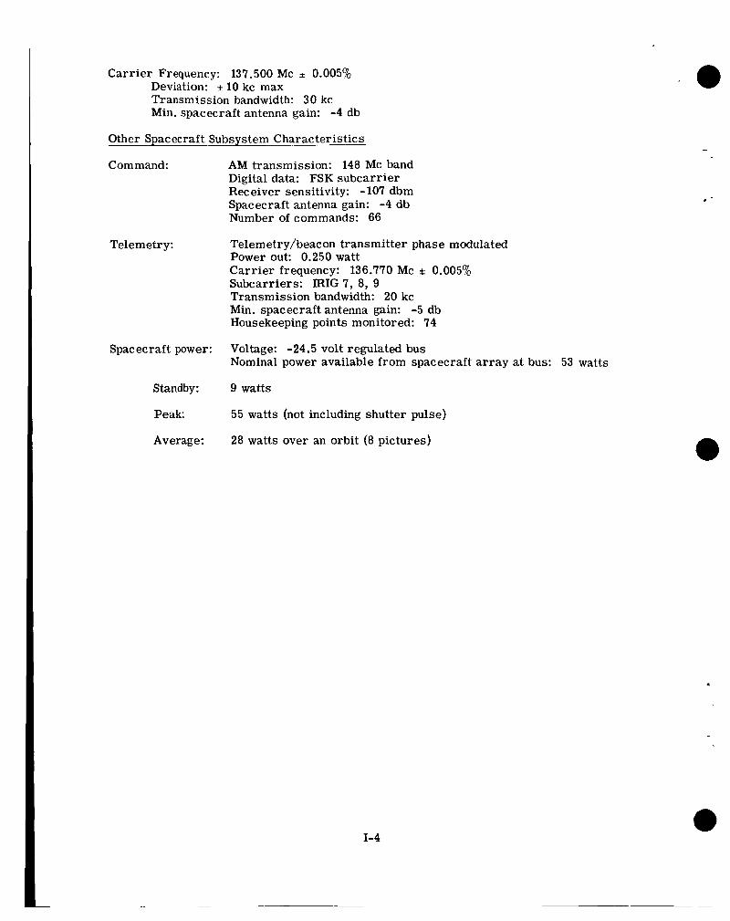
Carrier Frequency: 137.500 Mc f 0.005% Deviation: f 10 kc max Transmission bandwidth: 30 kc Min. spacecraft antenna gain: -4 db
Other Spacecraft Subsystem Character istic s
Com mand:
Telemetry:
Spacecraft power:
Standby:
Peak:
Average:
AM transmission: 148 MC band Digital data: FSK subcarrier Receiver sensitivity: - 107 dbm Spacecraft antenna gain: -4 db Number of commands: 66
Telemetry/beacon transmitter phase modulated Power out: 0.250 watt Carrier frequency: 136.770 Mc f 0.005% Subcarriers: IRIG 7, 8, 9 Transmission bandwidth: 20 kc Min. spacecraft antenna gain: -5 db Housekeeping points monitored: 74
Voltage: -24.5 volt regulated bus Nominal power available from spacecraft array at bus: 53 watts
9 watts
55 watts (not including shutter pulse)
28 watts over an orbit (8 pictures)
1-4
DATA SHEET
TOS AVCS
Spacecraft Characteristics
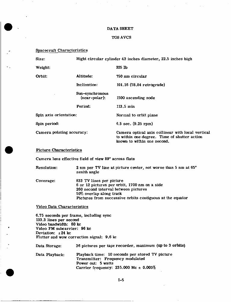
Size: Right circular cylinder 42 inches diameter, 22.5 inches high
Weight:
Orbit: Altitude:
hclLmtim:
Sun -synchronous (near -polar ):
Period:
Spin axis orientation:
Spin period:
Camera pointing accuracy:
325 lb
750 nm circular
101.16 (78.84 retrograde)
1500 ascending node
113.5 min
Normal to orbit plane
6.5 sec. (9.25 rpm)
Camera optical axis collinear with local vertical to within one degree. Time of shutter action known to within one second.
Picture Characteristics
Camera lens effective field of view 89" across flats
Resolution: 2 nm per TV line at picture center, not worse than 5 nm at 65" zenith angle
Coverage: 833 TV lines per picture 6 or 1.2 pictures per orbit, 1700 nm on a side 260 second interval between pictures 50% overlap along track Pictures from successive orbits contiguous at the equator
Video Data Characteristics
6.75 seconds per frame, including sync 133.3 lines per second Video bandwidth: 60 kc Video FM subcarrier: 96 kc Deviation: it24 kc Flutter and wow correction signal: 9.6 kc
Data Storage: 36 pictures per tape recorder, maximum (up to 3 orbits)
Data Playback Playback time: 10 seconds per stored TV picture Transmitter: Frequency modulated Power out: 5watts Carrier frequency: 235.000 Mc f 0.005%
1-5
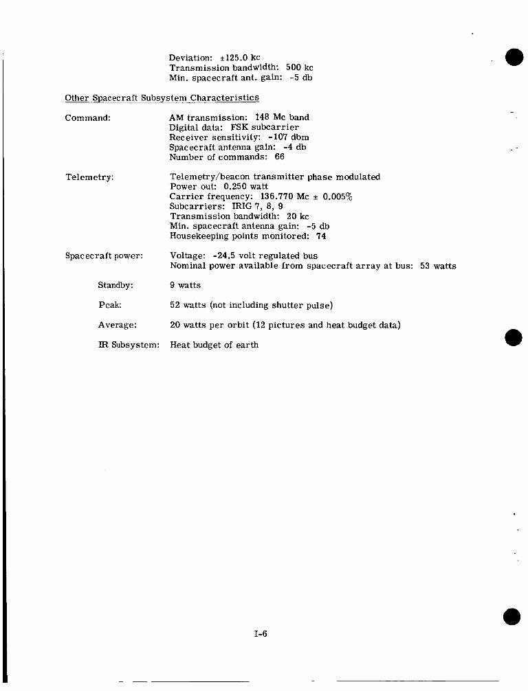
Deviation: * 125.0 kc Transmission bandwidth: 500 kc Min. spacecraft ant. gain: -5 db
Other Spacecraft Subsystem Characteristics
Com mand:
Telemetry:
AM transmission: 148 Mc band Digital data: FSK subcarrier Receiver sensitivity: -107 dbm Spacecraft antenna gain: -4 db Number of commands: 66
Telemetry/beacon transmitter phase modulated Power out: 0.250 watt Carr ier frequency: 136.770 Mc f 0.005% Subcarriers: IRIG 7, 8, 9 Transmission bandwidth: 20 kc Min. spacecraft antenna gain: -5 db Housekeeping points monitored: 74
Spacecraft power: Voltage: -24.5 volt regulated bus Nominal power available from spacecraft a r ray at bus: 53 watts
Standby: 9 watts
Peak: 52 watts (not including shutter pulse)
Average:
IR Subsystem:
20 watts per orbit (12 pictures and heat budget data)
Heat budget of earth
1-6
PART II
TOS SYSTEM OPERATIONAL PLAN
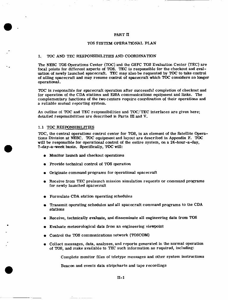
1. TOC AND TEC RESPONSIBILITIES AND COORDINATION
?he NESC TOS Operations Center (TOC) and the GSFC TOS Evalutiofi C a t e r (TEC) are focal points for different aspects of "OS. TEC is responsible for the checkout and eval- uation of newly launched spacecraft. TEC may also be requested by TOC to take control of ailing spacecraft and may resume control of spacecraft which TOC considers no longer o p e r a t i d .
TOC is responsible for spacecraft operation after successful completion of checkout and for operation of the CDA stations and ESSA communications equipment and links. The complementary functions of the two centers require coordination of their operations and a reliable mutual reporting system.
An outline of TOC and TEC responsibilities and TOC/TEC interfaces are given here; detailed responsibilities are described in Parts III and V.
1.1 TOC RESPONSIBILITIES TOC, the central operations control center for "OS, is an element of the Satellite Opera- tions Division at NESC. TOC equipment and layout are described in Appendix F. TOC will be responsible for operational control of the entire system, on a 24-hour-a-day, 'I-day-a-week basis. Specifically, TOC will:
Monitor launch and checkout operations
Provide technical control of "OS operation
Originate command programs for operational spacecraft
Receive from TEC prelaunch mission simulation requests or command programs for newly launched spacecraft
Formulate CDA station operating schedules
Transmit operating schedules and all spacecraft command programs to the CDA stations
Receive, technically evaluate, and disseminate all engineering data from TOS
Evaluate meteorological data from an engineering viewpoint
Control the TOS communications network (TOSCOM)
Collect messages, data, analyses, and reports generated in the normal operation of TOS, and make available to TEC such information as required, including:
Complete monitor files of teletype messages and other system instructions
Beacon and events data stripcharts and tape recordings
n- 1
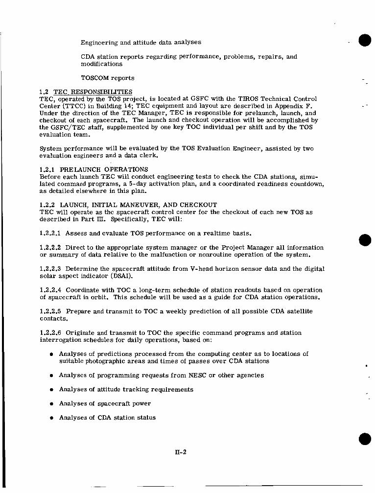
Engineering and attitude data analyses
CDA station reports regarding performance, problems, repairs, and modifications
TOSCOM reports
1.2 TEC RESPONSIBILITIES TEC, operated by the TOS project, is located at GSFC with the TIROS Technical Control Center (TTCC) in Building 14; TEC equipment and layout are described in Appendix F. Under the direction of the TEC Manager, TEC is responsible for prelaunch, launch, and checkout of each spacecraft. The launch and checkout operation will be accomplished by the GSFC/TEC staff, supplemented by one key TOC individual per shift and by the TOS evaluation team.
System performance will be evaluated by the TOS Evaluation Engineer, assisted by two evaluation engineers and a data clerk.
1.2.1 PRELAUNCH OPERATIONS Before each launch TEC will conduct engineering tests to check the CDA stations, simu- lated command programs, a 5-day activation plan, and a coordinated readiness countdown, as detailed elsewhere in this plan.
1.2.2 LAUNCH, INITIAL MANEWER, AND CHECKOUT TEC will operate as the spacecraft control center for the checkout of each new TOS as described in Part III. Specifically, TEC will:
1.2.2.1 Assess and evaluate TOS performance on a realtime basis.
1.2.2.2 Direct to the appropriate system manager or the Project Manager all information or summary of data relative to the malfunction or nonroutine operation of the system.
1.2.2.3 Determine the spacecraft attitude from V-head horizon sensor data and the digital solar aspect indicator (DSAI).
1.2.2.4 Coordinate with TOC a long-term schedule of station readouts based on operation of spacecraft in orbit. This schedule will be used as a guide for CDA station operations.
1.2.2.5 Prepare and transmit to TOC a weekly prediction of all possible CDA satellite contacts.
1.2.2.6 Originate and transmit to TOC the specific command programs and station interrogation schedules for daily operations, based on:
0 Analyses of predictions processed from the computing center as to locations of suitable photographic areas and t imes of passes over CDA stations
0 Analyses of programming requests from NESC or other agencies
0 Analyses of attitude tracking requirements
0 Analyses of spacecraft power
0 Analyses of CDA station status
II- 2
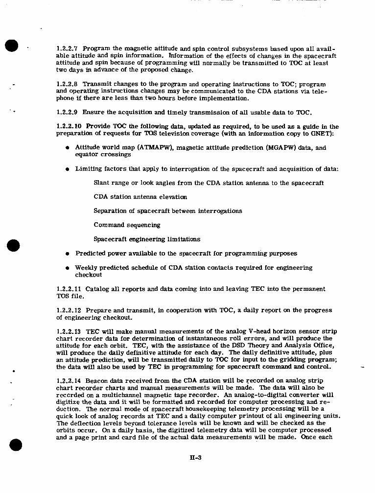
1.2.2.7 Program the magnetic attitude and spin control subsystems based upon all avail- able attitude and spin information. Information of the effects of changes in the spacecraft attitude and spin because of programming will normally be transmitted to Toc at least two days in advance of the proposed change.
1.2.2.8 Transmit changes to the program and operating instructions to TOC; program and operating instructions changes may be communicated to the CDA stations via tele- phone if there are less than two hours before implementation.
1.2.2.9 Ensure the acquisition and timely transmission of all usable data to TQC.
1.2.2.10 Provide TOC the following data, updated as required, to be used as a guide in the preparation of requests for TOS television coverage (with an information copy to GNET):
0 Attitude world map (ATMAPW), magnetic attitude prediction (MGAPW) data, and equator crossings
0 Limiting factors that apply to interrogation of the spacecraft and acquisition of data:
Slant range or look angles from the CDA station antenna to the spacecraft
CDA station antenna elevation
Separation of spacecraft between interrogations
Command sequencing
Spacecraft engineering limitations
0 Predicted power available to the spacecraft for programming purposes
a Weekly predicted schedule of CDA station contacts required for engineering checkout
1.2.2.11 Catalog all reports and data coming into and leaving TEC into the permanent TOS file.
1.2.2.12 Prepare and transmit, in cooperation with TOC, a daily report on the progress of engineering checkout.
1.2.2.13 TEC will make manual measurements of the analog V-head horizon sensor s t r ip chart recorder data for determination of instantaneous roll errors, and will produce the attitude for each orbit. TEC, with the assistance of the DSD Theory and Analysis Office, will produce the daily definitive attitude for each day. The daily definitive attitude, plus an attitude prediction, wi l l be transmitted daily to Toc for input to the gridding program; the data will also be used by TEC in programming f o r spacecraft command and control.
1.2.2.14 Beacon data received from the CDA station will be recorded on analog strii, chart recorder charts and manual measurements will be made. The data will also be reccrded on a multichannel magnetic tape recorder. An analog-to-digital converter will digitize the data and it will be formatted and recorded for computer processing and re- duction. Ihe normal mode of spacecraft housekeeping telemetry processing will be a quick look of analog records at TEC and a daily computer printout of all engineering units. The deflection levels beyond tolerance levels will be known and wil l be checked as the orbits occur. On a daily basis, the digitized telemetry data will be computer processed and a page print and card file of the actual data measurements will be made. Once each
II-3
week the card file will be input to one Of the GSFC plotters for a historical record plot of the telemetry parameters. These plots will become part of the permanent TOS files and will be used for spacecraft assessment as required.
1.3 TOC/TEC COORDINATION AND REPORTS The close relationship and interaction of the TOC and TEC operations will require close coordination of their activities and mutual reporting.
1.3.1 CONFLICTS DURING LAUNCH AND CHECKOUT During the launch and checkout period, TEC will originate the command programs for a new spacecraft. Simultaneously, TOC will have requirements to command existing TOS spacecraft. Scheduling conflicts in the use of CDA facilities and the communications network can arise. The following procedures will be used to prevent or resolve such conflicts.
Launch windows will be set to minimize conflicts. Replacement spacecraft will be launched into orbits nearly identical to those of the spacecraft replaced. However, in- jection time wi l l be planned so that the new spacecraft will be half an orbital period ahead of or behind the old one.
Before launch, DSD Theory and Analysis will study potential acquisition conflicts and develop a plan to avoid conflicts in the postlaunch checkout of the whole TOS system. The detailed plan will be issued before the launch of each new spacecraft. The predicted acquisition times for the replaced and the replacement TOS as well as the remaining operational TOS will be considered. bystem usage will be planned to allow both TEC checkout and TOC operational responsibilities to be satisfied to the greatest extent possible.
The Director of the NESC Office of Operations and the TOS Project Manager will approve this plan. Immediately after launch, the plan will be reviewed in light of the orbit achieved; changes will be made as required and approved by the manager and director.
If unanticipated conflicts develop during launch and checkout, the responsible persons at TEC and TOC will be required to work out solutions. (One possibility is that the noninterference-basis mutual backup agreements may be exercised to relieve CDA antenna-loading conflicts.) If agreement cannot be reached, an appeal will be made to the TOS Project Manager and to the NESC Office of Operations Director. In the event that time does not permit resolution of a conflict through the appeal channel, a decision must be made: during the two days immediately following launch, the new spacecraft will have priority and the TEC decision will prevail; at all other times TOC will make the final decision. If an arbitrary decision is made in this way, a report of the circumstances must be made to the appeal channel by those involved before leaving their duty posts for the day.
1.3.2 REPORTS AND OTHER COORDINATION ACTIVITIES
All reports and data generated in the normal operation of TOS will be collected by TOC and made available to TEC, including the processed telemetry data produced by DAPAF. The objective wil l be to provide processed data for both daily operations a d the evalua- tion task. To help achieve this, GSFC TOS project personnel will participate with members of NESC in working out specifications for data processing programs as well as for reports and other data.
11-4
2. CDA-TEC-TOC MISSION SIMULATION EXERCISE e - -
On a daily basis beginning seven days before launch, sample data will be transmitted from the CDA stations to TEC and TOC. The sample data will consist of video and beacon magnetic training tapes that will resemble as closely as possible the passes of telemetry and video from an actual spacecraft in orbit. Video simulator outputs w i l l also be used for video checks. The sample transmissions will be made on call by TEC via TOC at t imes that will not interfere with the missions of operational satellites. TEC will co- or&natc all schedules md programs with TOC, which will 'be monitoring all transmissions.
In addition to the daily tape transmissions, the CDA stations will compose and transmit appropriate teletype messages associated with the data. Just before the message text, each message w i l l read, "SAMPLE - - - - SAMPLE.''
Exercise initiation will begin at T-0 when TEC will transmit a sample TOS program to the CDA stations through TOC. Each CDA station will run the program tape through the CDA programmer and to the long line equipment for relay to TOC/TEC. TEC and TOC will process the received data and coordinate the timing and results. The simulation exercise results will be transmitted t o the CDA stations.
2.1 WALOMS SCHEDULE
0 T plus 15 minutes - WALOMS will transmit calibration signals to TEC
0 T plus 20 minutes - WALOMS will transmit the beacon training tape, monitor horizon sensor and DSAI recorded at the station, and report observations to TEC and TOC.
0 T plus 40 minutes - WALOMS will send the video data tape and selected video simu- lator outputs at 7-1/2 ips to TEC and TOC.
0 T plus 50 minutes - WALOMS will reduce the housekeeping telemetry and prepare the sample telemetry and pass summary messages.
0 T plus 60 minutes - WALOMS will transmit pass summary message, etc., to TEC and TOC.
2.2 GILMOR SCHEDULE
0 T plus 55 minutes - GILMOR will transmit calibration signals to TEC.
0 T plus 60 minutes - GILMOR will transmit the beacon training tape, monitor horizon sensor and DSAI data recorded at the CDA stations, and report observations to TEC and TOC.
0 T plus 80 minutes - GILMOR will send video data tape at 7-1/2 ips and selected video simulator outputs to TEC and TOC.
0 T plus 90 minutes - GILMOR will reduce the housekeeping telemetry and prepare the sample telemetry and pass summary messages.
0 T plus 100 minutes - GILMOR will transmit pass summary messages, etc., to TEC and TOC.
II- 5
3. FIVE-DAY ACTNATION P L A N
A complete interrogation and telemetry tracking schedule, identical to that to be followed on launch day and the succeeding four days, will be originated by TOC and disseminated to all participating groups approximately two weeks before launch. Beginning on D-9 through D-5 a test run will be simulated for the complete five-day plan. The simulation schedule may be modified by TOC if necessary to obtain operational data from orbiting satellites.
4. COORDINATED READINESS
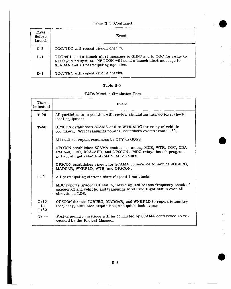
TEC will initiate coordinated readiness operations beginning ten days before launch. T&DS will exercise STADAN; the CDA stations will be scheduled by TOC as requested by TEC (Table II-1).
5. T&DS MISSION SIMULATION TEST
T&DS will conduct a TOS mission simulation test under the direction of the OPSCON Operations Director and the coordination of the Tracking and Data Systems Manager.
All TOS, NESC, CDA, OPSCON/NETCON, and WTR personnel who will participate in the actual launch operations will be present. Details will be forwarded by TTY to each ele- ment of the launch communications net; an outline of events is listed in Table II-2.
All TTY and telephone circuits into OPSCON will be initiated at the direction of the Operations Director.
II-6
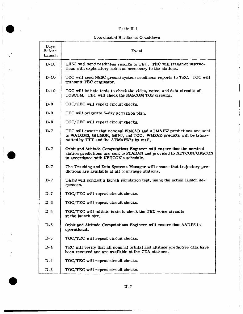
Table II-1
Days Before Launch
D-10
D-10
-10
D-9
D-9
D-8
D-7
D-7
D-7
D-7
0-7
D- 6
0-5
D- 5
0-5
D-4
D-4
D-3
Coordinated Readiness Countdown
Event
GHNJ will send readiness reports to TEC. TEC will transmit instruc- tions with explanatory notes as necessary to the stations.
TOC will send NESC ground system readiness reports to TEC. TOC will transmit TEC originator.
TOC wiii initiate tests to check the video, voice, and data circuits cf TOSCOM. TEC will check the NASCOM TOS circuits.
TOC/TEC will repeat circuit checks.
TEC will originate 5-day activation plan.
TOC/TEC will repeat circuit.checks.
TEC will ensure that nominal WMSAD and ATMAFW predictions are sent to WALOMS, GILMOR, GHNJ, and TOC. WMSAD predicts will be trans- mitted by TTY and the ATMAPW's by mail.
Orbit and Attitude Computations Engineer will ensure that the nominal station predictions are sent to STADAN and provided to NETCON/OPSCON in accordance with NETCON's schedule.
The Tracking and Data Systems Manager will ensure that trajectory pre- dictions are available at all dcwnrange stations.
T&DS wil l conduct a launch simulation test, using the actual launch se- quence s . TOC/TEC will repeat circuit checks.
TOC/TEC will repeat circuit checks.
TOC/TEC will initiate tests to check the TEC voice circuits at the launch site.
Orbit and Attitude Computations Engineer will ensure that M P S is operational.
TOC/TEC will repeat circuit checks.
TEC will verify that all nominal orbital and attitude >redictive data have been received and are available at the CDA stations.
TOCITEC will repeat circuit checks.
TOC/TEC will repeat circuit checks.
II-7
Days Before Launch
D- 2
D- 1
D- 1
Table 11-2
T&DS Mission Simulation Test
Event
TOC/TEC will repeat circuit checks.
TEC wi l l send a launch-alert message to GHNJ and to TOC for relay to NESC ground system. NETCON will send a launch alert message to STADAN and all participating agencies.
TOC/TEC will repeat circuit checks.
Time :minutes)
T-90
T-60
T+ 0
T+10 to
T+30
T+ --
Event
A l l participants in position with review simulation instructions; check local equipment
OPSCON establishes SCAMA call to WTR MDC for relay of vehicle countdown. WTR transmits nominal countdown events from T-30.
A l l stations report readiness by TTY to GOPS
OPSCON establishes SCAMA conference among MCR, WTR, TOC, CDA stations, TEC, RCA-AED, and OPSCON. MDC relays launch progress and significant vehicle status on all circuits
OPSCON establishes circuit for SCAMA conference to include JOBURG, MADGAR, WNKFLD, WTR, and OPSCON.
Al l participating stations start elapsed-time clocks
MDC reports spacecraft status, including last beacon frequency check of spacecraft and vehicle, and transmits liftoff and flight status over all circuits on LOS.
OPSCON directs JOBURG, MADGAR, and WNKFLD to report telemetry frequency, simulated acquisition, and quick-look events.
Post-simulation critique will be conducted by SCAMA conference as re- quested by the Project Manager
lo - PART IU
GSFC OPERATIONS
i - 8 -
.
The TOS project is responsible for spacecraft systems and readiness and for ensuring readiness of all systems for each launch.
The Tracking and Data Systems (T&DS) Directorate is responsible for the operation of STADAN and GSFC ground communications system and for orbital computations and predictions.
(NESC operation of its TOS grmmd system is mtlherl in P.rt V of this p b zzd described in detail in ESSA publications.)
1. TEC TEC, operated by the TOS project, is responsible for spacecraft control during the launch and checkout phases until TOC acceptance of the operational spacecraft.
Before that time, TEC will analyze and evaluate all spacecraft data, review ground sta- tion and TOC reports, and forward a summary of findings and recommendations to the Project Manager and TOC each day; when the spacecraft is Operational, a report on the checkout phase will be filed. The reports will include comments on ground stations and communications performance.
During spacecraft checkout, TEC personnel will evaluate spacecraft performance on a realtime basis. Special attention will be given to attitude during the turnaround maneuver. The performance of the communication and electrical systems used during the turn- around will be recorded and observed for engineering purposes, along with careful checks of the various units of the power system.
Prelaunch Operations. For a two-week period preceding a TOS launch, TEC will prepare for the launch and postlaunch operations. Simulated launch operations will be conducted, with T&DS and TOC coordination. All shifts of the TOS ground system will participate: WALOMS, GILMOR, TEC, TOC, RCA-AED. TEC will transmit simulated command pro- grams to the CDA stations via TOC and supplement the programs with direct voice contact during the scheduled operation. Video and beacon data, either simulated or obtained from an operational TOS, will be received and processed at TEC. Engineering tests will be run to prove out the CDA stations. Normally, TEC 24-hour prelaunch operations will be con- ducted only during the last few days before launch.
Launch and Initial Maneuver. TEC will operate as the spacecraft control center for the launch and checkout of the TOS. TEC will generate command programs and ground sys- tem schedules. TOC will include the TEC requirements in their weekly schedule. TEC will transmit the program to the action and information addresses. TOC will transmit their weekly schedule to GFOM. NETCON wil l transmit the NETCON schedules to ULASKA. At Fairbanks, the DAF shift supervisor integrates the two schedules. TEC will have voice contacts with GILMOR, WALOMS, RCA-AED, and the launch net on lines monitored by TOC. The CDA stations will transmit data from the APT and AVCS TOS via TOSCOM to TEC and TOC for processing as required. Later system review may in- dicate the need for additional narrow bandwidth facilities; existing GSFC lines may be used. The initial maneuver commands will be generated at TEC to place the satellite in an operational position. Once the operational position has been achieved, the checkout and performance evaluation of the satellite w i l l proceed.
nr- 1
Checkout Plan and Performance Evaluation. The TOS project will prepare a checkout plan for each spacecraft and submit it to ESSA for review and approval. During the checkout period, TOC w i l l monitor all operations of the new TOS. When the Director of the NESC Office of Operations and the TOS Project Manager agree that the spacecraft is operational, TOC will assume responsibility. The plan will list in detail the operational tests that must be successfully completed to check out a newly launched TOS.
Operational Mode. After control of the spacecraft has been assumed by TOC, the GSFC TOS evaluation team will conduct long-term analyses of the spacecraft data. The evalua- tion team will normally use raw data recorded at TOC and operational analysis produced by DAPAF. Occasionally, TEC will be used to obtain special TOS data.
When a s e r i o u s problem ar i ses in the operation of the spacecraft, TOC may request TEC to assume responsibility for determining the nature and extent of the problems, and to determine if there are means of bypassing the difficulty.
1.1 SYSTEMS OPERATIONS - LAUNCH AND CHECKOUT PLAN Systems operations for TEC will include:
0 Realtime systems assessment and evaluation
0 Near-real-time systems evaluation
0 Attitude determination and maneuvering
0 Scheduling and programming
0 Engineering documentation and reporting I
0 Equipment maintenance, operation, and calibration
1.1.1 REALTIME SYSTEMS ASSESSMENT AND EVALUATION
1.1.1.1 Prepass Functions
0 Review program of pass to be interrogated
0 Review spacecraft subsystem status, based on previous orbit program and telemetry
0 Establish voice and data contact with CDA station interrogating spacecraft
1.1.1.2 Functions During: a Pass
0 Check quality of recorder data
0 Veri fy spacecraft status from preinterrogation telemetry data; issue command program additions as required
0 Verify normal systems operations during readout; issue operational changes as required
1.1.1.3 Postpass Functions -
0 Evaluate data quality of recordings
Reduce status housekeeping telemetry from str ip chart recorder data; maintain daily history of selected data
Verify all spacecraft subsystems status and update spacecraft status board
Evaluate station events records and pass summaries
Complete operations log, including a summary of all events relevant to the interro- gated orbit
Prepare data relative to next interrogation
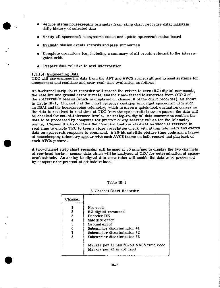
1.1.1.4 Engineering Data TEC will use engineering data from the APT and AVCS spacecraft and ground systems for assessment and realtime and near-real-time evaluation as ioiiows:
An 8-channel s t r ip chart recorder will record the return to zero (RZ) digital commands, the satellite and ground e r ro r signals, and the time-shared telemetries from SCO 3 of the spacecraft's beacon (which is displayed on channel 8 of the chart recorder), as shown in Table III-1. Channel 8 of the chart recorder contains important spacecraft data such as DSAI and the housekeeping telemetry, which is given a quick-look evaluation onpass as the data is received in real time at TEC from the spacecraft; between passes the data will be checked for out-of-tolerance levels. An analog-to-digital data conversion enables the data to be processed by computer for printout of engineering values for the telemetry points. Channel 8 also contains the command confirm verification which is received in real time to enable TEC to keep a close correlation check with status telemetry and events data on spacecraft response to command. A 20-bit satellite picture time code and a frame of housekeeping telemetry appear with each AVCS frame on both record and playback of each AVCS picture.
A two-channel s t r ip chart recorder will be used at 50 mm/sec to display the two channels of vee-head horizon sensor data which will be analyzed at TEC for determination of space- craft attitude. An analog-to-digital data conversion will enable the data to be processed by computer for printout of attitude values.
Table III-1
8-Channel Chart Recorder
7 8
Not used RZ digital command Decoder RZ Satellite error Ground er ror Subcarrier discriminator #1 Subcarrier discriminator #2 Subcarrier discriminator #3
Marker pen #1 has 28-bit NASA time code Marker pen $12 is not used
m- 3
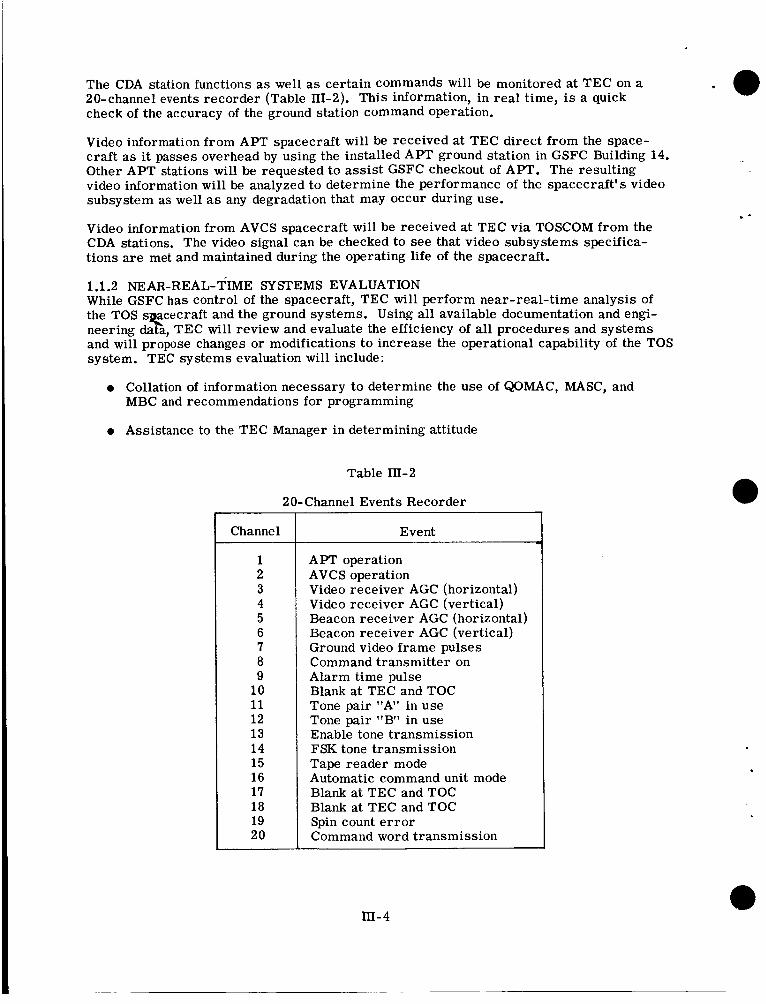
The CDA station functions as well as certain commands will be monitored at TEC on a 20-channel events recorder (Table HI-2). This information, in real time, is a quick check of the accuracy of the ground station command operation.
Video information from APT spacecraft will be received at TEC direct from the space- craft as it passes overhead by using the installed APT ground station in GSFC Building 14. Other A P T stations will be requested to assist GSFC checkout of APT. The resulting video information will be analyzed to determine the performance of the spacecraft's video subsystem as well as any degradation that may occur during use. .- Video information from AVCS spacecraft will be received at TEC via TOSCOM from the CDA stations. The video signal can be checked to see that video subsystems specifica- tions are met and maintained during the operating life of the spacecraft.
1.1.2 NEAR-REAL-TIME SYSTEMS EVALUATION While GSFC h a s control of the spacecraft, TEC will perform near-real-time analysis of the TOS secec ra f t and the ground systems. Using all available documentation and engi- neering data, TEC will review and evaluate the efficiency of all procedures and systems and will propose changes or modifications to increase the operational capability of the TOS system. TEC systems evaluation will include:
0 Collation of information necessary to determine the use of QOMAC, MASC, and MBC and recommendations for programming
0 Assistance to the TEC Manager in determining attitude
Table III-2
20-Channel Events Recorder
Channel
1 2 3 4 5 6 7 8 9
10 11 12 13 1 4 15 16 17 18 19 20
Event
APT operation AVCS operation Video receiver AGC (horizontal) Video receiver AGC (vertical) Beacon receiver AGC (horizontal) Beacon receiver AGC (vertical) Ground video frame pulses Command transmitter on Alarm time pulse Blank at TEC and TOC Tone pair "A" in use Tone pair "B" in use Enable tone transmission FSK tone transmission Tape reader mode Automatic command unit mode Blank at TEC and TOC Blank at TEC and TOC Spin count e r ro r Command word transmission
rn- 4
0 Formulation of procedures to be followed in attitude determination
0 Suggestions for changes in techniques
0 Evaluation of performance of all spacecraft and ground systems
1.1.3 MANUAL ATTITUDE DETEFWINATION Attitude will be determined in accordance with procedures established in TEC and in accordance with the geometry in Figures IIi-1, m-2, and III-3.
1.1.3.1 Prepass Functions
0 Review and evaluate attitude data received on previous readout
0 Determine attitude values predicted for readout
1.1.3.2 Function During a Pass
0 Evaluate attitude data quality during readout
1.1.3.3 Postpass Functions
0 Initiate attitude determination process by placing the 2-channel strip chart record on Gerber scanner; review entire readout and select sky-earth and earth-sky transitions for measurements
.
0 Determine maximum roll angle ( 6 max)
0 Determine time after descending node when maximum roll angle occurred (A)
0 Determine spin rate
0 Predict spin decay and attitude change
0 Determine requirements for QOMAC and MASC programming
0 Determine spacecraft nutation or precession angle
0 Determine gamma angle from DSAI data
0 Compare attitude and spin data with data from CDA stations
0 Compare attitude and spin values with data from M P S
0 Compare attitude values with predicted values
0 Plot all comparative attitude and spin data
1.1.4 TEC EQUIPMENT OPERATION, CALIBRATION, AND MAINTENANCE
1.1.4.1 Communications Lines All voice and data information from the CDA stations is transmitted via TOSCOM system to TEC over two X-136 microwave terminals (receive onlv). TEC can talk and transmit TTY messages and commands to the CDA stations via voice TTY circuits through TOSCOM switchboards; equipment is listed in Appendix G.
III- 5
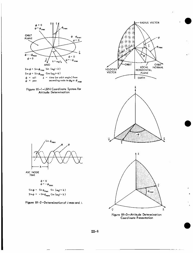
A N 0
Sin + = Sin
Sin $ = Sin
Sin (oat - A 1 COS (00 t -A
= roll A = time (or orbit ongle) from
4 = yaw ascending node to +o or $,,,
Figure Ill-1-LBN Coordinate System for Attitude Determination
RADIUS VECTOR
ASC NODE TIME
+ = 0 JI = -b,,,
Sin$ = Sin4max Sin (oat- A ) Sin$ = -Sin$maxCos ( o o t - A )
Figure Ill-2-Determinationof 6 maw and A
Figure I I I -3-Attitude Determination Coord i note Presentation
III- 6
The CDA stations will be transmitting the following information to TEC during normal operations:
0 Time-shared beacon SCO #3 with satellite picture time count
- -
0 Vee-head sensor data (SCO #l and #2)
0 Station events
0 Flutter and wow (slowed-down recording)
0 Satellite picture time count (slowed-down recording)
a Yidw (skmed-dcrcr, recordire)
0 Voice
0 TTY
Spacecraft data and attendant voice coordination will have precedence over all other use o f the lines.
At least once a week each line wil l be tested for frequency response using an audio oscil- lator at the CDA station, level at 0-dbm, and frequency steps of 300 cps between 300 and 4000 cps. If obvious trouble is evident on any line, the test will be re-run using steps of 100 cps. The test will be run at any time there is reason to believe the line is not adequate for data transmission. The TOS AVCS signal simulator may also be used for line calibration.
When the line level at TEC drops below -3db from zero within the 300-cps to 4000-cps band or when the level shows more than lOdb change from the lowest to the highest points, then the line will be referred to the shift supervisor and a decision made to re- turn the line to the TOSCOM switchboard as inadequate for data reception or transmission.
When data, live or taped, is lost as a result of a defective line, the time of loss of line and return will be logged in the operations log.
1.1.4.2 Logs The shift chief is responsible for the maintenance of all logs.
Shift Chief's Log. The shift chiefs will maintain a record of operational items, decisions and problems as well as a summary of each shift's operation and information to be passed on to the next shift.
Communications and Operations Log. The equipment operator will record all details of the communications lines (\evels, tests and lost time). Noise and signal levels, frequency, phase, and amplitude tests; time of loss of line, and time of return will be entered in this log, along with entries pertaining to the equipment operation, data type, orbit numbers, and time of receipt of all da ta
Maintenance and Test Equipment Log. All details of the checkout, calibration, malfunction, repair, and lost time on all equipment and test equipment a re to be entered in this log by the maintenance and equipment operator.
m- 7
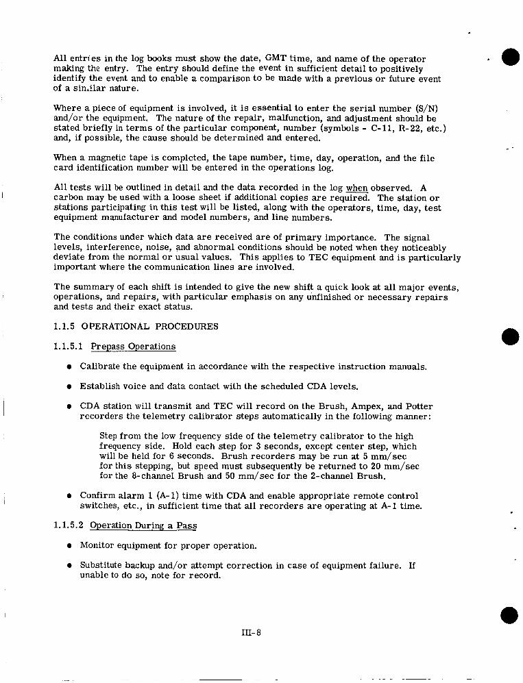
All entries in the log books must show the date, GMT time, and name of the operator making the entry. The entry should define the event in sufficient detail to positively identify the event and to enable a comparison to be made with a previous o r future event of a s inAar nature.
Where a piece of equipment is involved, it is essential to enter the serial number (S/N) and/or the equipment. The nature of the repair, malfunction, and adjustment should be stated briefly in te rms of the particular component, number (symbols - C-11, R-22, etc.) and, if possible, the cause should be determined and entered.
When a magnetic tape is completed, the tape number, time, day, operation, and the file card identification number will be entered in the operations log.
All tes ts wil l be outlined in detail and the data recorded in the log when observed. A The station o r
stations participating in this test will be listed, along with the operators, time, day, test equipment manufacturer and model numbers, and line numbers.
I carbon may be used with a loose sheet if additional copies a r e required.
The conditions under which data are received a re of primary importance. The signal levels, interference, noise, and abnormal conditions should be noted when they noticeably deviate from the normal o r usual values. This applies to TEC equipment and is particularly important where the communication lines are involved.
The summary of each shift is intended to give the new shift a quick look at all major events, operations, and repairs, with particular emphasis on any unfinished or necessary repairs and tests and their exact status.
1.1.5 OPERATIONAL PROCEDURES
1.1.5.1 Prepass Operations
e Calibrate the equipment in accordance with the respective instruction manuals.
e Establish voice and data contact with the scheduled CDA levels.
e CDA station wi l l transmit and TEC will record on the Brush, Ampex, and Potter recorders the telemetry calibrator steps automatically in the following manner:
Step from the low frequency side of the telemetry calibrator to the high frequency side. Hold each step for 3 seconds, except center step, which will be held for 6 seconds. Brush recorders may be run at 5 mm/sec for this stepping, but speed must subsequently be returned to 20 mm/sec for the 8-channel Brush and 50 mm/sec for the 2-channel Brush.
e Confirm alarm 1 (A-1) time with CDA and enable appropriate remote control switches, etc., in sufficient time that all recorders are operating at A-1 time.
1.1.5.2 Operation During a Pass
e Monitor equipment for proper operation.
e Substitute backup and/or attempt correction in case of equipment failure. If unable to do so, note for record.
111- 8
I .
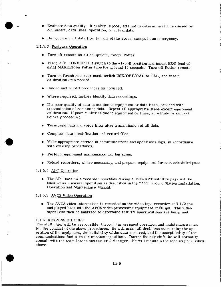
0 Evaluate data quality. If quality is poor, attempt to determine i f it is caused by equipment, data lines, operation, or actual data.
0 Do not interrupt data flow for a n y of the above, except in an emergency.
1 .1 .5 .3 Postpass Operation
0
0
0
0
0
0
0
0
0
0
0
Turn off remote 011 all equipment, except Potter
Place A,'D CONVERTER switch to the -1-volt position and insert EOD (end of data) MAFUER on Potter tape for at least 15 seconds. Turn off Potter remote.
Turn on Brush recorder used, switch USE/OFF/CAL to CAL, and insert calibration ontn rernrd.
Unload and reload recorders as required.
Where required, further identify data recordings.
If a poor quality of data is not due to equipment o r data lines, proceed with transmission of remaining data. Repeat all appropriate steps except equipment calibration. If poor qu'dity is due to equipment o r lines. substitute or correct before proceeding.
Terminate data and voice links after transmission of all data.
Complete data identification and record files.
Make appropriate entries in communications and operations logs, in accordance with existing procedures.
Perform equipment maintenance and log same.
Reload recorders, where necessary, and prepare equipment for next scheduled pass.
1 .1 .5 .4 APT Operation
0 The APT facsimile recorder operation during a TOS-APT satellite pass will be handled as a normal operation as described in the "APT Ground Station Installation, Operation and Maintenance Manual."
1 .1 .5 .5 AVCS Video Operation
0 The AVCS video information is recorded on the video tape recorder at 7 112 ips and played back into the AVCS video processing equipment at 60 ips. The video signal can then be analyzed to determine that T V specifications are being met.
1.1 .6 RESPONSIBILITIES The shift chief will be responsible, through his assigned operation and maintenance man, for the conduct of the above procedures. He will make all decisions concerning the op- eration of the equipment, t h e suitability of t h e data received, and the acceptability of the communications facilities for mission operations. During the day shift, h e will normally consult with the team leader and the TEC Manager. He will maintain the logs as prescribed above.
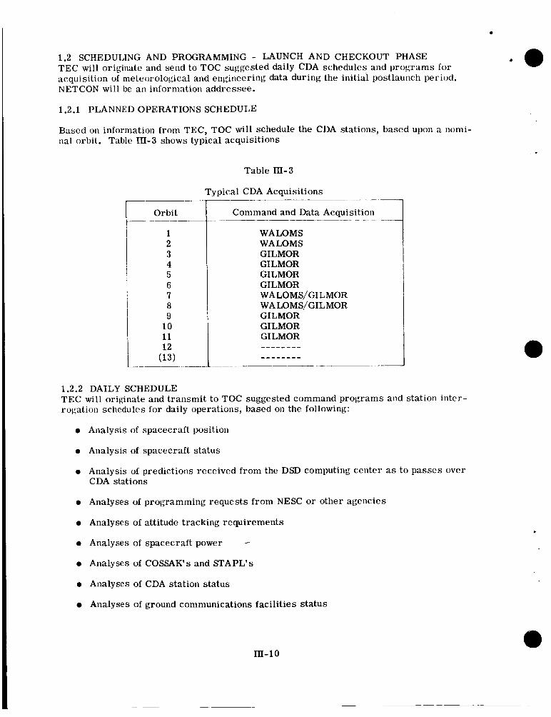
1.2 SCHEDULING AND PROGRAMMING - LAUNCH AND CHECKOUT PHASE TEC will originate and send to TOC suggested daily CDA schedules and programs for acquisition of meteorological and engineering data during the initial postlaunch wriod. NETCON will be an information addressee.
1.2.1 PLANNED OPERATIONS SCHEDULE
Based on information from TEC, TOC will schedule the CDA stations, based upon a nomi- nal orbit. Table In-3 shows typical acquisitions
Table 111-3
Typical CDA Acquisitions
Orbit
1 2 3 4 5 6 7 8 9
10 11 12
(13)
- _ _ Command and Data Acquisition
_ _ _ _ _ _ _ _ _ - - .
WALOMS WALOMS GILMOR GILMOR GILMOR GILMOR WALOMS/GILMOR WA LOMS/GILMOR GILMOR GILMOR GILMOR - - - - - - - - --------
______ ______- __
1.2.2 DAILY SCHEDULE TEC will originate and transmit to TOC suggested command programs and station inter- rogation schedules for daily operations, based on the following:
0 Analysis of spacecraft position
0 Analysis of spacecraft status
0 Analysis of predictions received from the DSD computing center as to passes over CDA stations
0 Analyses of programming requests from NESC or other agencies
0 Analyses of attitude tracking requirements
0 Analyses of spacecraft power - 0 Analyses of COSSAK's and STAPL's
0 Analyses of CDA station status
Analyses of ground communications facilities status
m - 1 0
*
l a I - -
I - i -
, -
1.2.3 SPACECRAFT PROGRAMMING TEC will provide programs for TOC to program the spacecraft for engineering and meteorological information based upon the following factors:
Spacecraft attitude and spin rate
Spacecraft power available
Spacecraft subsystem status
Meteorological requirements
CDA station schedule
CDA station acquisitions
Areas suitable for photographic coverage
CDA station status
Ground communications facilities status
TEC will program the magnetic attitude and spin control subsystems via TOC, based upon all available attitude and spin information. TEC will transmit information on the effects of programming changes in the spacecraft attitude and spin to TOC.
TEC will transmit changes to the program and operating instructions to TOC. If there are two hours or less before implementation, TEC will communicate with TOC and the CDA stations via voice; if there are more than two hours, TEC will send TOC a TTY with SS precedence. NETCON will be kept informed of all GILMOR operations for proper sched- uling.
1.2.4 SCHEDULING AND PROGRAMMING REQUIREMENTS
Data required by TEC from the Theory and Analysis Office for use in spacecraft pro- gramming and CDA station scheduling until the ESSA takeover are:
A 28-day WMSAD listing WALOMS and GILMOR - available to TEC at least two weeks before the first date of the data.
Two 14-day ATMAPW's - available to TEC at least four days before the first date of the data.
A 28-day COSSAK - available to TEC at least two weeks before the first date of the data.
Equator crossings.
Picture prediction times.
Predictive attitude and spin data.
In-11
1.3 ENGINEERING DOCUMENTATION AND REPORTING TEC will evaluate and analyze all TOS data and prepare a daily report for the TEC Man- ager. All reports received from the CDA stations, including pass summaries, pass pic- ture Summaries, daily picture summaries, and all other operations records, will be thoroughly analyzed. Data from the reports will be tabulated and used as the basis for a daily narrative report and a final report. The analytical summaries will be complete appraisals of the entire TOS system, including the spacecraft and all ground elements, events of each day, and all anomalies and failures.
The TEC Manager, in conjunction with NESC, will prepare and transmit a daily progress report on TOS operations.
1.4 COMMUNICATIONS AND DATA TRANSMISSION
1.4.1 CDA STATION STATUS If data cannot effectively be transmitted from a CDA station o r received at TEC, o r if CDA station computation and analysis facilities are not operative, TEC, via TOC, will reschedule station interrogation responsibilities. Rescheduling will be accomplished within the framework of the overall planning schedule when possible.
Problems encountered at the CDA stations that affect the station's capability for effective command and data readout in addition to the capabilities of adequate computation, proces- sing, and analysis of the data will be reported to NESC, which is responsible for ensuring that immediate action is taken.
Difficulties with communications facilities will be reported to TOC, which will assess the problem and take corrective action when possible.
TEC will inform the cognizant systems manager when difficulties occur in his system operation.
1.4.2 DATA TRANSMISSION TEC will have the following responsibilities for receiving TOS data:
0 Request the scheduling of voice and data lines for receiving TOS operational data from the CDA stations and to and from TEC and NESC
0 Provide TOC, in a timely manner, all operational data for the CDA stations
0 Coordinate with DSD for computer communications
1.4.3 DATA PROVIDED TO TOC TEC will provide NESC the following data:
0 Spacecraft status
0 Limiting factors that apply to interrogation of the spacecraft and acquisition of data
0 Predicted power available to the spacecraft for programming purposes
0 Requested schedule of CDA station operations
1.5 GRAPHIC DISPLAYS TEC will maintain the following special graphic displays:
0 Selected telemetry points versus time
111-12
~8 -
, - _
0 Spin rate versus time
0 Spin vector coordinates ( @ max and A ) using MGAPW and the daily operational definitive attitude values
0 Sun-spin vector angle ( T ) versus time, using MGAPW and daily operational definitive values
0 Power available to the spacecraft p r day and the daiiy power consumption versus time
0 Daily interrogation schedule
0 Spacecraft status
0 CDA station status
0 Ground communications facility status
lo
2. ORBIT AND ATTITUDE DETERMINATION The GSFC Data Systems Division (DSD) will be responsible for systems readiness for early orbit determination and for checkout of the automatic attitude determination sys- tem. DSD will determine the TOS orbit, prepare World Map and Satellite Acquisition Data (WMSAD's) and STADAN and CDA station predictions, determine spacecraft atti- tude using the Automatic Attitude Determination Program System (AADPS), provide attitude predictions, and furnish associated orbit and attitude data as required by the TOS project. When the new TOS is accepted by NESC, DSD support requirements are reduced to TOS orbit determination, minute vector tape production, and provision of STADAN station predictions.
The Orbit and Attitude Computations Engineer, R. D. Werking of the Theory and Analysis Office, has the responsibility for coordination of the early orbit and automatic attitude determination plans. The Orbit and Attitude Computations Engineer will assist NESC by providing orbital data to be used at TOC. He will also provide assistance to TEC in the determination of the best attitude for each orbit of the day and will prepare reports and documents as may be necessary, including a postflight analysis.
The Orbit and Attitude Computations Engineer will be responsible for conducting the orbit determination; including the differential correction, i.e., for the selection, evaluation, and interpretation of the data; the selection of the orbit and attitude theories and the differential correction theory; the analysis and interpretation of the results, the use of the results for predictions, and releasing the results for other operational purposes; and the determina- tion as to when the operation has been completed.
. The Advanced Orbital Programming Branch is responsible for programming support as may be needed because of special project demands. The Branch will arrange for repre- sentation from the programming staff during the orbit determination period to provide, in an emergency, detailed information on the capabilities of the entire orbit determination program library, as well as guidance in the u s e of such programs.
The Orbit Determination Section, Operational Computing Branch, is responsible for the preparation and prompt machine computation of world maps and station predictions and for any special computations that may be required. The section will be responsible for the availability and proper running of the various programs used for orbit determination and predictions; it will arrange for suitable representation from the section during the launch and orbit determination period.
IiI- 13
The Minitrack Section, Operational Computing Branch, will receive the nominal station predictions prior to launch and is responsible for appropriate processing and transmittal of this to the tracking stations. It will also be responsible for the preparation of a sched- ule of estimated early tracking data acquisitions for use during the launch and orbit de- termination period. The section will arrange for suitable representation during the launch and orbit determination period, and will be responsible for receipt and processing of tracking data for input to the IBM 7094 general orbit determination system. In addition, it will be responsible for conversion of prediction data from magnetic tape to paper tape and transfer to NASCOM for transmission to TOC.
The Computer Services Section, Operational Computing Branch, wil l be responsible for arranging for the presence of the computer operating personnel and for the use of the necessary computing facilities.
2.1 DSD PRELAUNCH SUPPORT Prior to the launch of each TOS macecraft a complete melaunch analvsis will be D e r - formed by DSD and the results wiil be published in a document entitled, "Prelaunch Analy- sis for TOS." A complete manpower list, including the names of persons involved with early orbit and attitude determination will be distributed within DSD.
2.1.1 ORBIT ANALYSIS AND SYSTEM READINESS
Nominal orbital data will be computed from the Delta vehicle trajectory parameters taken directly from the appropriate DTO for the satellite in question. These trajectory param- e te rs taken at third-stage burnout will be used in the Conversion Routine for Orbital Ele- ments (CORFOE) and/or the Douglas transformation program for the computation of the nominal orbital elements.
2.1.2 AUTOMATIC ATTITUDE DETERMINATION PROGRAM SYSTEM (AADPS)
The Orbit and Attitude Computations Engineer will be responsible for the attitude deter- mination and spacecraft status data for TOS during the launch and checkout phase. AADPS, consisting of proven computer programs for digital horizon scanner and telemetry data preprocessing, horizon determination, roll angle computation, status data processing and evaluation; attitude and status analysis, and attitude prediction, will be operated by the Theory and Analysis Office under the direction of the Orbit and Attitude Computations Engineer. The data will be supplied to TEC after each orbit until the wheel orientation is achieved, at which time the data will be supplied on a daily basis or upon special request.
Two modes of attitude determination are employed in AADPS. One mode uses a least- squares-fit of roll observations, while the other mode uses a smoothed-roll observation/ sun observation pair to compute spin vector orientation.
A plan for attitude determination using sun and roll observations will be devised for the initial maneuver, given nominal orbit and attitude maneuvers for each TOS spacecraft. This data will be contained in "Prelaunch Analysis for TOS" report to be provided before each launch,
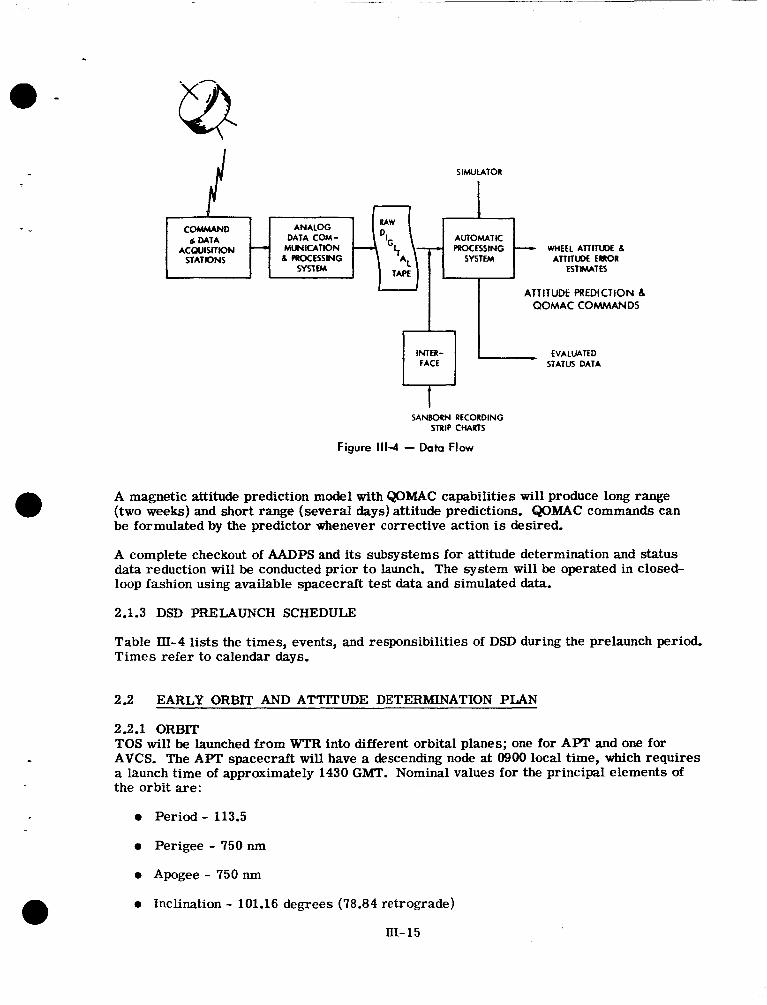
Roll observations obtained from the V-head horizon scanner sensor and sun observations obtained from the digital solar aspect indicator are transmitted to TEC as an analog signal. This signal is processed through an analog-to-digital converter and supplied to the Theory and Analysis Office in the form of a digital tape. Shown in Figure III-4 is the data flow from the satellite to the computer; Figure JII-5 is the automatic attitude de- termination computer system.
HI- 14
COMmAND 6 DATA
STATIONS ACQUISITION -
SANBORN RECORDING STRIP CHAKTS
AUTOMATIC PROCESSING WHEEL ATTITWE 6
ATTITCRL ERROR ESTWATES
ANALOG DATA COM-
MUNICATION 6 PROCESSING
m f m
Figure 111-4 - Data Flow
A magnetic attitude prediction model with QOMAC capabilities will produce long range (two weeks) and short range (several days) attitude predictions. QOMAC commands can be formulated by the predictor whenever corrective action is desired.
a A complete checkout of AADPS and its subsystems for attitude determination and status data reduction will be conducted prior t o launch. The system will be operated in closed- loop fashion using available spacecraft test data and simulated data.
2.1.3 DSD PRELAUNCH SCHEDULE
Table III-4 lists the times, events, and responsibilities of DSD during the prelaunch period. Times refer to calendar days.
2.2 EARLY ORBIT AND ATTITUDE DETERMINATION PLAN
2.2.1 ORBIT TOS will be launched from WTR into different orbital planes; one for APT and one for AVCS. The APT spacecraft will have a descending node at 0900 local time, which requires a launch time of approximately 1430 GMT. Nominal values for the principal elements of the orbit are:
0 Period- 113.5
0 Perigee - 750 nm
0 Apogee - 750 nm
0 Inclination - 101.16 degrees (78.84 retrograde)
lII-15
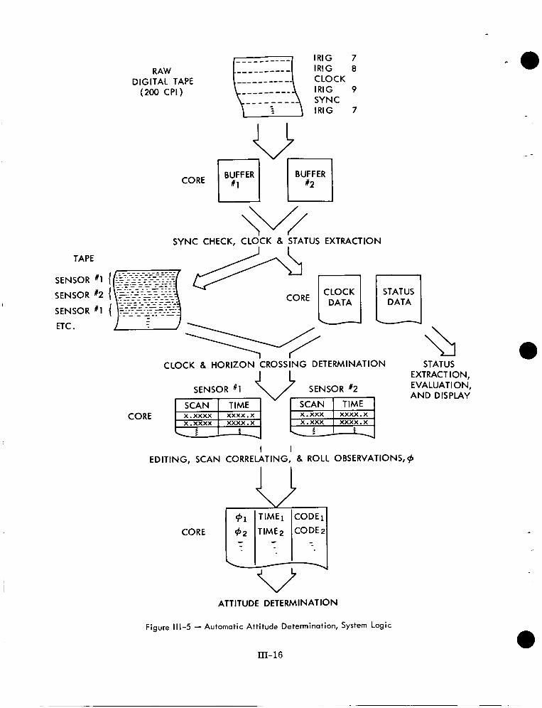
RAW DIGITAL TAPE (200 CPI)
CORE
SYNC CHECK, CLOCK 8 STATUS EXTRACTION
TAPE
SENSOR # I
SENSOR #2
SENSOR # I
ETC .
CORE
CLOCK STATUS DATA
L
CLOCK 8 HORIZON CROSSING DETERMINATION
SENSOR # I I SCAN I T I M E I - SCAN T I Y E I x . xxxx xxxx . x x.xxx xxxx.x x . xxxx xxxx . x x.xxx xxxx.x
I 5 4 \ ; I 5
I I EDITING, SCAN CORRELATING, 8 ROLL OBSERVATIONS, #
CORE
ATTITUDE DETERM I N AT 10 N
Figure 111-5 - Automatic Attitude Determination, System Logic
III- 16
STATUS EXTRACTION, EVALUATION, AND DISPLAY
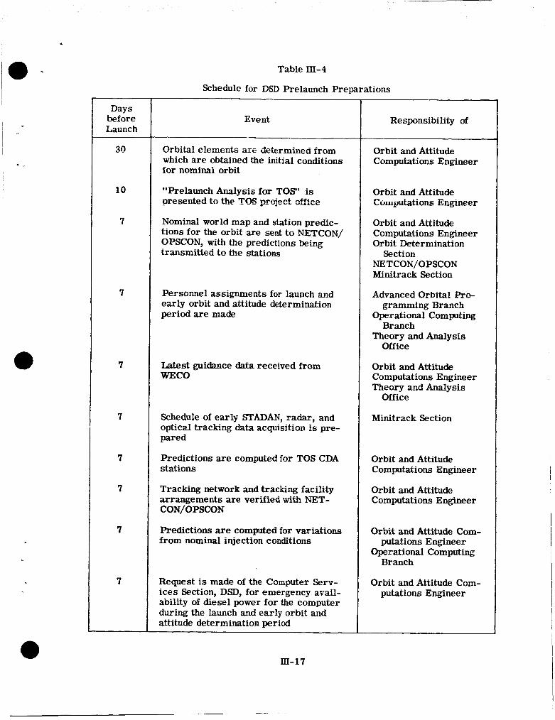
~- i -
, - -
Days before Launch
30
10
7
7
7
7
7
7
7
7
Table m-4
Schedule for DSD Prelaunch Preparations
Event
Orbital elemefits are determined from which are obtained the initial conditions for nominal orbit
"Prelaunch Analysis for TOS' is presented to the TCE pcject &ice
Nominal world map and station predic- tions for the orbit are sent to NETCON/ OPSCON, with the predictions being transmitted t o the stations
Personnel assignments for launch and early orbit and attitude determination period a re made
Latest guidance data received from WECO
Schedule of early STADAN, radar, and optical tracking data acquisition is pre- pared
Predictions are computed for TOS CDA stations
Tracking network and tracking facility arrangements are verified with NET- CON/OPSCON
Predictions are computed for variations from nominal injection conditions
Request is made of the Computer Serv- ices Section, DSD, for emergency avail- ability of diesel power for the computer during the launch and early orbit and attitude determination period
Responsibility of
Orbit and Attitude Computations Engineer
Orbit and Attitude Computations Engineer
Orbit and Attitude Computations Engineer Orbit Determination
Section NETCON/OPSCON Minitrack Section
Advanced Orbital Pro- gramming Branch
Operational Computing Branch
Theory and Analysis Office
Orbit and Attitude Computations Engineer Theory and Analysis
Office
Minitrack Section
Orbit and Attitude Computations Engineer
Orbit and Attitude Computations Engineer
Orbit and Attitude Com- putations Engineer
Operational Computing Branch
Orbit and Attitude Com- putations Engineer
EI-17
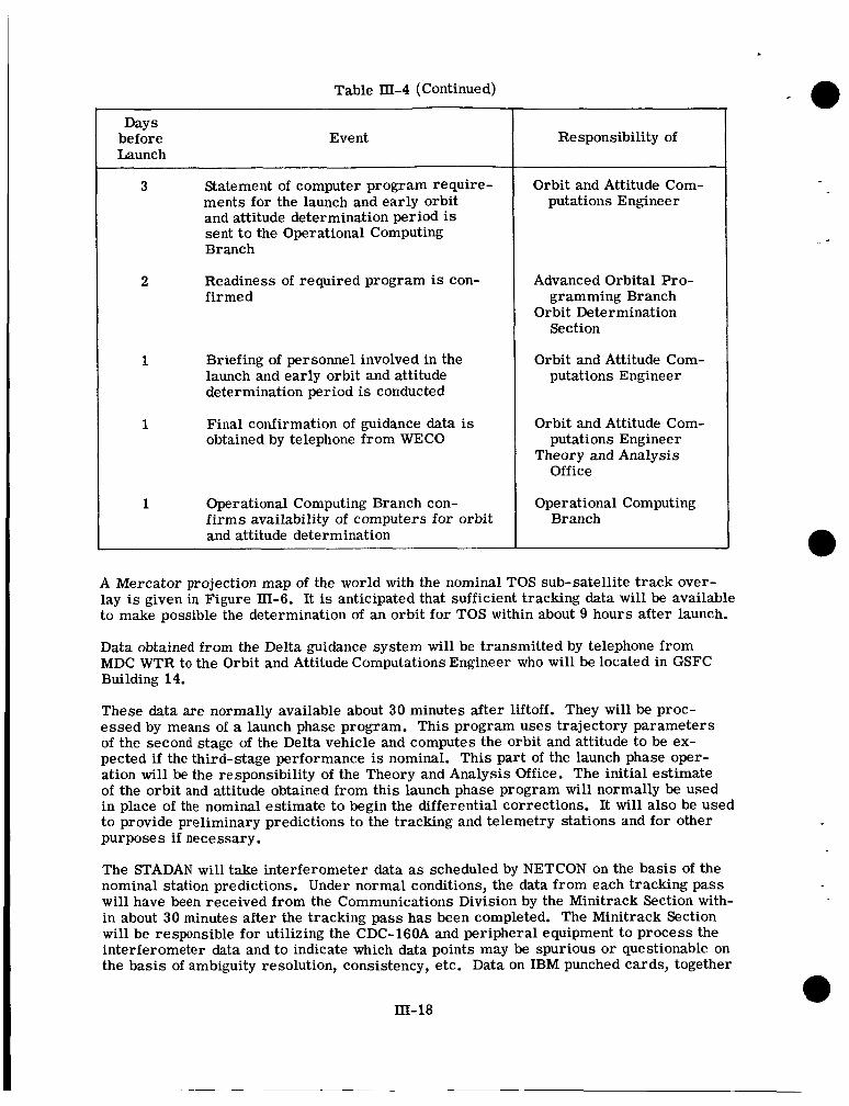
Table III-4 (Continued)
Days before Event Launch
3 State me nt of computer program re quire - ments for the launch and early orbit and attitude determination period is sent t o the Operational Computing Branch
2 Readiness of required program is con- firmed
1 Briefing of personnel involved in the launch and early orbit and attitude determination period is conducted
1 Final confirmation of guidance data is obtained by telephone from WECO
1 Operational Computing Branch con- f i rms availability of computers for orbit and attitude determination
Responsibility of
Orbit and Attitude Com- putations Engineer
Advanced Orbital Pro- gramming Branch
Orbit Determination Section
Orbit and Attitude Com- putations Engineer
Orbit and Attitude Com- putations Engineer
Theory and Analysis Office
Operational Computing Branch
A Mercator projection map of the world with the nominal TOS sub-satellite track over- lay is given in Figure III-6. It is anticipated that sufficient tracking data will be available to make possible the determination of an orbit for TOS within about 9 hours after launch.
Data obtained from the Delta guidance system will be transmitted by telephone from MDC WTR to the Orbit and Attitude Computations Engineer who will be located in GSFC Building 14.
These data are normally available about 30 minutes after liftoff. They will be proc- essed by means of a launch phase program. This program uses trajectory parameters of the second stage of the Delta vehicle and computes the orbit and attitude to be ex- pected if the third-stage performance is nominal. This part of the launch phase oper- ation will be the responsibility of the Theory and Analysis Office. The initial estimate of the orbit and attitude obtained from this launch phase program will normally be used in place of the nominal estimate to begin the differential corrections. It will also be used to provide preliminary predictions to the tracking and telemetry stations and for other purposes if necessary.
The STADAN will take interferometer data as scheduled by NETCON on the basis of the nominal station predictions. Under normal conditions, the data from each tracking pass will have been received from the Communications Division by the Minitrack Section with- in about 30 minutes after the tracking pass has been completed. The Minitrack Section will be responsible for utilizing the CDC-16OA and peripheral equipment to process the interferometer data and to indicate which data points may be spurious o r questionable on the basis of ambiguity resolution, consistency, etc. Data on IBM punched cards, together
III-18
.
I - -
(Please insert Figure III-6, TOS APT and AVCS Subsatellite Tracks from page III-20 of the orig- inal TOS Mission Operations Plan.)
In-1 9
with indications of the potential usefulness, will be handcarried to the Orbit Determina- tion Section representative. Under normal conditions the data will have been processed and evaluated by the Minitrack Section and made available for use in the IBM 7094 with- in about 15 minutes after they have been received from the Communications Division. The Orbit Determination Section representative will be responsible for processing the interferometer data in the general orbit determination input program and for preparing the data tape for use in the general orbit determination differential correction program. During the early orbit determination phase, the interferometer data will not be smoothed. Under normal conditions, the data will have been processed by means of the general orbit determination input program within about five minutes after being received at the IBM 7094.
Data from the normal T&DS support agencies will be received by the Minitrack Section where they will be transferred to punched cards and made available for use in the IBM 7094. These tracking data cards will be received and processed by means of the general orbit determination program within about 50 minutes after receipt at GSFC.
The general orbit determination programs, including the input program, the differential correction program, the station prediction programs, and such other programs as may be needed, will be operated by personnel of the Orbit Determination Section and the Computer Services Section under the direction of the Orbit and Attitude Computations Engineer. When a satisfactory orbit has been obtained on the basis of data from at least three interferometer passes spanning an interval of at least one orbit, preliminary orbital information will be provided to TEC, TOC, and NETCON/OPSCON. These results will be confirmed by carrying out a differential correction with respect to the interferom- e te r data from four or more interferometer tracking passes. When this has been done, and a satisfactory result has been achieved, the early orbit determination can be con- sidered to have been completed. However, for the first 24 hours o r until otherwise ad- vised, the interferometer data should be available for processing by the Minitrack Sec- tion no later than one hour after each pass has been completed. This requirement is placed upon OPSCON to ensure that data is transmitted from the stations to COMPUT to be made available to the Orbit Determination Section when attempts are made to up- date the TOS orbit. The Orbit and Attitude Computations Engineer will notify OPSCON when this service is no longer needed.
Improved orbital elements and predictions based upon additional tracking observations will then be released. The Orbit and Attitude Computations Engineer and the Orbit De- termination Section representative will be responsible for providing world maps and printed versions of the station predictions and aler ts to TEC, OPSCON, and NETCON. They will also be responsible for furnishing prediction magnetic tapes to the Minitrack Section and a position vector tape to TOC. The Minitrack Section will be responsible for transmitting the teletype versions of the station predictions to the Communications Division.
2.2.2 ATTITUDE
TOS will be placed in orbit with a spin axis orientation similar to the conventional TIROS satellites. The spacecraft spin axis will be in or very near the orbital plane and in the general direction of the velocity vector at injection. The operational orientation is to keep the spin axis perpendicular to the orbital plane which requires the initial wheel maneuver. The orientation maneuver should begin on the first orbit and continue for about 18 orbits. sible.
It is important, therefore, to determine the orbit as soon as pos-
To assist in making the determination, two sources of data will be used. All available injection data will be studied and attitude data in the form of horizon scanner and sun
III- 2 0
aspect data obtained from the satellite will be processed. Tne injeciiuii &tz iviZ zct iis a start ing point for the rest of the work which will follow.
The attitude data will be received at TEC via the telephone lines from the ground station. After this data is received, digitized, and recorded in TEC, it is processed by AADPS on an IBM 7094. The results are then given to TEC with suggested attitude correction commands. Also supplied to TEC is the status data which was processed through AADPS.
All cif L%s support will be supplied on a pass-by-pass basis until the initial maneuver has been completed or until the Orbit and Attitude Computations Engineer determines that the need for pass-by-pass coverage no longer exists.
During the launch and checkout phase of a TOS mission, orbit and attitude data will be supplied by DSD to various groups. Following is a list of data to be supplied t o OPSCON, TEC, and TOC. OPSCON will receive the world map and sTAuAiU predictions, equator crossings, and orbital elements. This information will be supplied every seven days, using the latest orbital information available.
For the f i r s t month after launch, TEC will be provided with printouts predicting orbital and picture data and attitude data at the intervals listed:
0 A 28-day WMSAD listing GILMOR and WALOMS - available two weeks before f i r s t date of data
0 14-day ATMAPW - available four days before the first date of the data
0 A 28-day COSSAK - available two weeks before first date of data
0 1-day definitive and 3-day predictive Magnetic Attitude Prediction Wheel-Attitude Smoothing Program (MGAPW-ASP) - available each day
0 Status Data Extraction, Evaluation, Reduction (STADEE) - available each day
Both MGAPW and STADEE will be supplied on an orbit-by-orbit basis until the reorien- tation maneuver has been completed.
The data to be supplied by-DSD during the checkout phase is centered around the genera- tion of the position vector tape. The first of these tapes will be made available at the end of the early orbit determination phase. Also to be made available will be the computa- tion of CDA station prediction data. In general this will consist of ENV data which are used to produce drive tapes for the 85-foot dish antennas.
The second position vector tape will be provided approximately three days after launch. Tracking data will be generated and made available to TOC and to ULASKA. This will then become an operational procedure.
Attitude and status data will be provided at regular intervals depending upon the needs of TEC.
3. GSFC OPERATIONS CONTROL
3.1 OPSCON The T&DS Operations Director in the GSFC Operations Control Center (OPSCON) is responsible for control of the GSFC ground support facilities used during launch. The following may be in OPSCON to assist in the operations.
In-21
. 0 Assisl;inl Operations Director
0 Tracking and Data Systems Manager
0 Network Controller
0 Tracking and Telemetry Engineer
0 Operations Controller
0 Display Manager
0 NORAD Liaison
3.2 MISSION CONTROL ROOM The Mission Control Room (MCR) is divided into two areas. One area is designed for use by GSFC Management personnel and the other area is for use by project personnel. Communication facilities are provided in the management area for monitoring the op- erational activity. A hot line is also available for direct communication with the Project Manager at the range. The following persons may be in attendance in the MCR management area.
I
0 GSFC Director - Dr. J. F. Clark
0 GSFC Deputy Director - Dr. J. W. Townsend, Jr.
0 GSFC Assistant Director for T&DS - Mr. J. T. Mengel
0 GSFC Assistant Director for Projects - Mr. R. E. Bourdeau
0 Other management personnel as invited
The individuals located in the project a rea of the MCR will have access to communica- tions as required during the mission. The project a rea of the MCR will accommodate six individuals. The following persons may be in this area:
0 Project Representative
0 Orbit and Attitude Computations Engineer
0 NASA Headquarters Representative
0 Launch Vehicle Representative
0 ESSA Representative
0 Public Information Officer
3.3 TELEPHONE COMMUNICATIONS OPSCON telephone communications are established to provide for rapid liaison, co- ordination, and/or data dissemination during the mission.
I 3.4 DISPLAYS Prelaunch and realtime launch data pertaining to the mission a re displayed on illumi- nated screens located at the front of OPSCON. The following information will be
III-22
a - displayed during the launch and early orbit phase: all of the information may not be displayed simultaneously, displays will be projected a s appropriate data is received.
3.4.1 STATION STATUS The current status of each participating STADAN station is shown by means of in- dividual colored lights placed at the geographic station location on the world map. The lights indicate the following:
0 Amber - station iivt reported or status unkno*.vn
0 Red - station not ready
0 Green - station ready
0 Flashing green - acquisition of spacecraft signal
0 Amber following flashing green - loss of spacecraft signal
3.4.2 LAUNCH EVENTS AND ORBITAL ELEMENTS This display presents the nominal and real times of the sequence of events during launch, the nominal and computed orbital elements, and other pertinent information related to the launch vehicle and spacecraft.
3.4.3 DOPPLER PLOT A nominal doppler plot is displayed. This is a plot of the spacecraft R F frequency shift versus time in seconds. Beginning at liftoff, doppler data will be received on a realtime basis and automatically plotted to indicate the actual velocity performance of the launch vehicle.
3.4.4 MESSAGE DISPLAY This display is used to view projected mission-oriented teletype messages received from the supporting stations.
3.4.5 FLIGHT PATH ANGLE VERSUS VELOClTY RATIO This display graphically shows the data received in real time by the GSFC computers. The display indicates the flight path angle versus the ratio of the actual velocity to the velocity which is required to inject the spacecraft into the desired orbit. Three scales are used, each increasing the last by a factor of ten.
3.4.6 SUBSATELLITE PLOT The nominal subsatellite plot for one or more orbits is displayed. The position of the spacecraft along this plot will be indicated in real time if near nominal orbit is achieved. It is expected that the subsatellite plot will be maintained for no more than seven hours.
3.4.7 COUNTDOWN CLOCK The countdown clock indicates the latest terminal count as received in OPSCON from WTR. Hold times are also indicated.
3.4.8 GMT CLOCK A clock indicating GMT is mounted directly above the countdown clock.
3.4.9 PROJECTION SCREEN A projection screen in the top center is used to view 35-mm slides which show the terminal count and other launch activities.
III-23
3.4.10 TRACKING AND TELEMETRY SCHEDULE This schedule sequentially shows the stations which will acquire spacecraft tracking and telemetry data.
3.5 TELEVISION Closed-circuit television from OPSCON will be transmitted to the NASA Headquarters Mission Status Room. This monitor will enable the NASA Headquarters personnel to observe the launch activity available in OPSCON. Television monitors will be estab- lished in the auditorium of Building 3, GSFC. These monitors will permit those GSFC personnel not admitted to the restricted access of OPSCON to observe the launch activity,
111- 2 4
PART IV
FIELD OPERATIONS
Field operations for a TOS/WTR launch are conducted by elements of Unmanned h m c h Operations (ULO), Kennedy Space Center (SC), Western Test Range (WTR), the TOS project, the GSFC Space Tracking and Data Acquisition Network (STADAN), the CDA stations, APT stations, and the ground communications net.
1. ULO AND TOS PROJECT
ULO is responsible for Delta launch operations at WTR. ULO is responsible for assuring the accomplishment of all actions necessary for the launch of the TOS spacecraft into orbit, including planning the launch, coordination among NASA, contractors, and the range; range documentation; arranging for the necessary launch support by contractors and other government agencies; establishment and operation of Mission Director Center (MDC) at WTR; and reporting to the Project Manager as established in the TOS Project Development Plan (PDP).
2. WTR FACILITIES
WTR facilities used for an Improved Delta launch include Vandenberg Air Force Base (VAFB) and South Vandenberg Air Force Base (SVAFB) (Figure IV-1). Down-range radar at San Nicholas Island and radar ships are used for launch tracking. The VAFB and SVAFB facilities used for TOS launches include Space Launch Complex-2 East (SLC-BE) (Figure IV-2) and blockhouse, the spacecraft laboratory and telemetry station in Building 34 (Figure IV-3), the Delta Operations Bldg., the WECO ground station, and the NASA of- fices and Mission Director Center (MDC) in Building 32 (Figure IV-4).
SLC-BE includes the blockhouse (CC- l), the Delta Operations Bldg., vehicle shelters, gantry, umbilical mast, RF tower, and two concrete reinforced shelters for support equip ment. The blockhouse control room and launch assignments are shown in Figure IV-5.
The NASA/ULO spacecraft laboratory in Building 34 provides facilities for .spacecraft preparation checkout, and handling. Spacecraft assembly area A is a 2380-square-foot high bay; spacecraft assembly area B is a 2856-square-foot low bay. There are also 7 individual labs and a 10,000-square-foot high-bay service area. The nominal temperature is 70" + 3°F with a relative humidity less than 50% except in the high-bay service area.
The KSC/ULO office, the Mission Director Center (MDC), Observation Room, and the Communications Center are in Building 32 (Figure IV-6).
The MDC provides communications and display facilities for prelaunch and postlaunch operations. The facilities include two x-y vertical plotting boards, a range readiness board, vehicle events baards, communications consoles, two 2 1-inch TV monitors, and two digital clocks providing PST/PDT and GMT time.
The NASA/KSC telemetry ground station is located in Building 34, VAFB. The station provides telemetry and Doppler coverage for all prelaunch, launch, and postlaunch operations.
IV- 1
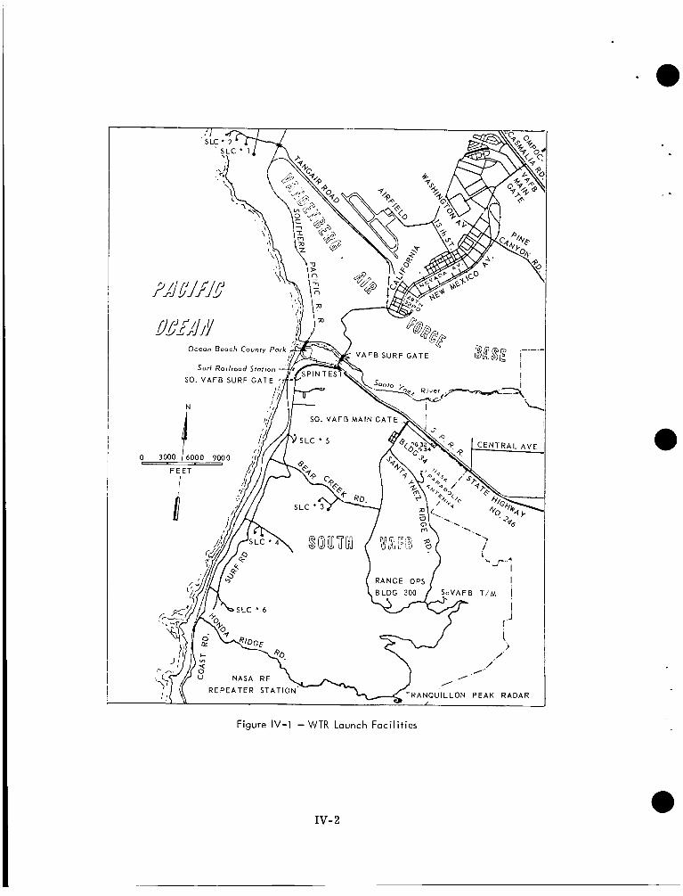
Figure IV-1 - WTR Launch Facilities
IV- 2
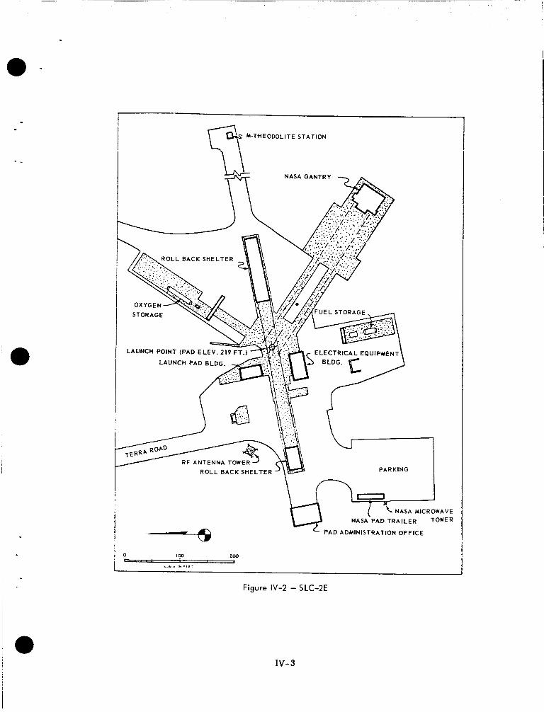
. -
I M-THEODOLITE STA TlON
I \ n
I -
I -
~ - -
a
NASA MICROWAVE
NASA PAD TRAILER TOWER
PAD ADMINISTRATION OFFICE
Figure IV-2 - SLC-2E
IV- 3
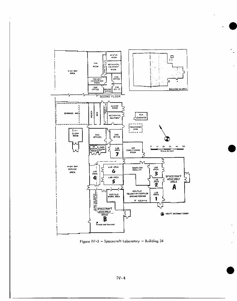
- e
HIGH BAY 1 AREA
f PIN
ROOM
WILDING 34 AREA 1
CLEAN
w
HIGH BAY
I SERVICE AREA I
I i
El GENERATOR
C -
ENG ENG OFFICES OFFICE
0 IO 20 30 40 50 w - w
SCALE I N FEET ROOM
I- I
7 A % % COMPUTER
r , r 2 I FACILITY
SPACECRAFT ASSEMBLY
AREA A
T
@ 450 CT ANTENNA TOWER
Figure IV-3 - Spacecraft Laboratory - Building 34
IV- 4
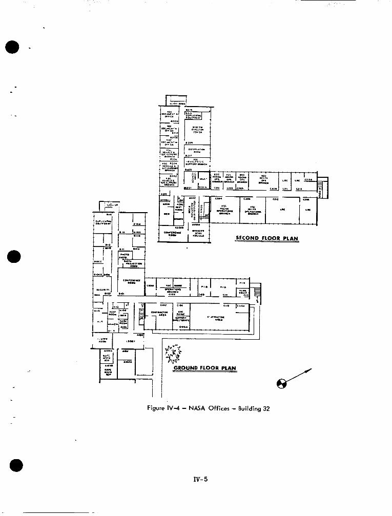
e -
-.
J c c . w w u i Y F 1 .,““Lo SECOND FLOOR PLAN
I LO”. .
GROUND FLOOR PLAN
Figure IV-4 - NASA Offices - Building 32
lv- 5
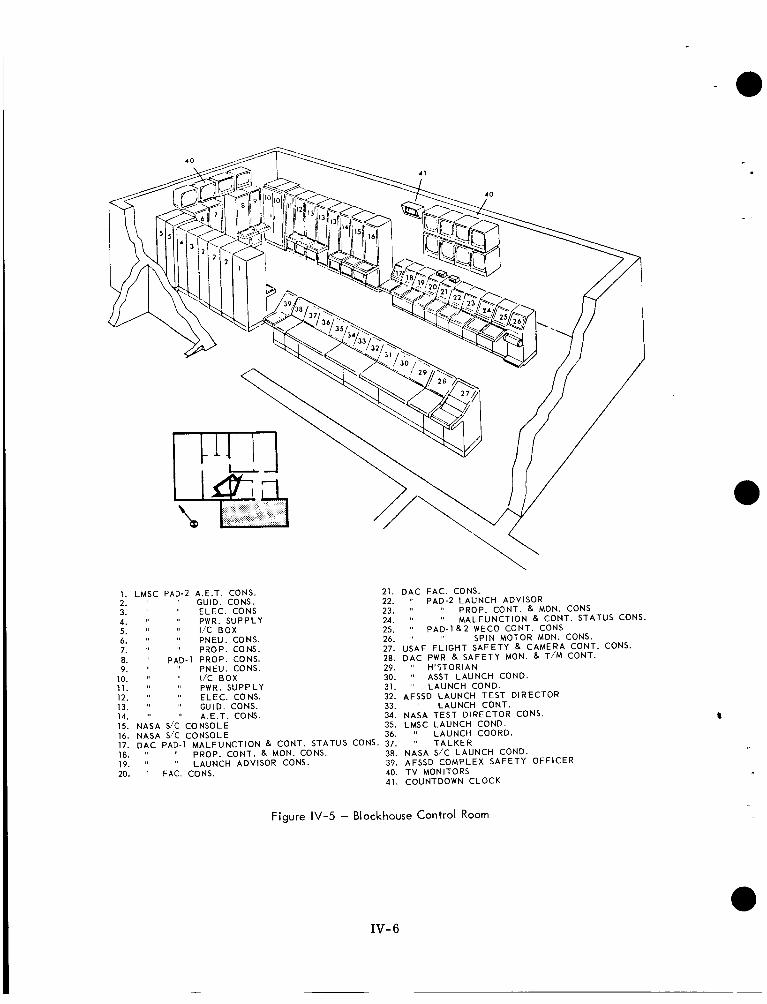
1. LMSC PAD-2 A.E.T. CONS. 21. OAC FAC. CONS. 2. " " GUID. CONS. 22. PAD-2 LAUNCH ADVISOR 3. " " ELEC. CONS 23. ' I ' I PROP. CONT. & MON. CONS 4. " " PWR. SUPPLY 24. " " MALFUNCTION R CONT. STATUS CONS.
6. '' " PNEU. CONS. 26. '' " SPIN MOTOR MON. CONS. 7. " PROP. CONS. 27. USAF F L I G H T SAFETY 8 CAMERA CONT. CONS. 8. " PAD-1 PROP. CONS. 28. OAC PWR R SAFETY MON. R T I M CONT. 9. " " PNEU. CONS. 29. " H '5TORIAN
5. ' I I/C BOX 25. 1 3 P A D - ~ R ~ WECO CONT. CONS
10. " " I/C BOX 30. ' I ASST LAUNCH CONO. 11. " '' PWR. SUPPLY 31. " LAUNCH COND. 12. " " ELEC. CONS. 32. AFSSD LAUNCH TEST DIRECTOR 13. " " GUIO. CONS. 33. " LAUNCH CONT. 14. " ' I A.E.T. CONS. 34. NASA TEST DIRECTOR CONS. 15. NASA SIC CONSOLE 35. LMSC LAUNCH CONO. 16. NASA SIC CONSOLE 36. " LAUNCH COORO. 17. D A C PAD-1 MALFUNCTION R CONT. STATUS CONS. 37. " T A L K E R 18. I ' " PROP. CONT. 8, MON. CONS. 38. NASA S/C LAUNCH CONO. 19. " " LAUNCH ADVISOR CONS. 39. AFSSO COMPLEX SAFETY OFFICER 20. " FAC. CONS. 40. T V MONITORS
41. COUNTDOWN CLOCK
Figure IV-5 - Blockhouse Control Room
IV- 6
4
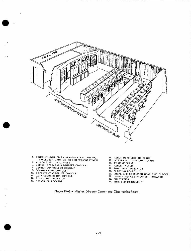
1-5. CONSOLES (MANNED B Y HEADQUARTERS, MISSION, SPACECRAFT, AND V E H I C L E REPRESENTATIVES)
6. MISSION DIRECTOR CONSOLE 7. L A U N C H OPERATIONS MANAGER CONSOLE 8. CENTER CONTROLLER CONSOLE 9. COMMUNICATOR CONSOLE
10. DISPLAYS CONTROLLER CONSOLE 11. D A T A COORDINATOR CONSOLE 12. PLUS COUNT INDICATOR 13. PERSONNEL LOCATOR
14. 1s. 16. 17. 18. 19. 20. 21. 22. 23.
Figure 1V-6 - Mission Direc tor C e n t e r a n d
RANGE READINESS INDICATOR I N T E G R A T E D COUNTDOWN CHART T V MONITORS (2 ) RANGE T A L K E R TIME COUNT INDICATOR P L O T T I N G BOARDS (2) L O C A L AND GREENWICH MEAN TIME . - L A U N C H V E H I C L E PROGRESS INDICA P I 0 STATION MOPS E N D INSTRUMENT
O b s e r v a t i o n Room
CLOCKS TOR
IV- 7
R F reception is by the %-foot parabolic tracking antenna (NASA/TRK- 1) located on Santa Ynez ridge, antennas located on Building 34 on a 450-foot tower, and a steerable NASA-9 antenna, with a 148-mc command element installed, and a trihelix antenna for vehicle telemetry and backup support mounted on the roof of Building 34.
Command capabilities include a 50-watt and a 5-kw transmitter for closed loop command checkout and all command requirements.
Vehicle telemetry support includes real-time display of all vehicle telemetry functions on Sanborn or CEC recorders in addition to magnetic tape recordings.
3. WTR ORGANIZATION
NASA activities at WTR are the responsibility of KSC/ULO Western Test Range Opera- tions (WTRO). Figure IV-7 shows the WTRO organizational structure.
3.1 NASA RANGE SUPPORT The NASA Range Support (NRS) Office is the point of contact for NASA Range U s e r func- tions with WTR. NRS assures that mission support requirements specified by NASA projects a r e properly prepared and coordinated, and are submitted to AFWTR in accord- ance with overall policy.
3.2 RANGE OPERATIONS BRANCH The Range Operations Branch is divided into sections that function as part of the composite NRS and is the point of contact with AFWTR organizations for each WTRO program. The Delta Missions Office is the Range contact for all Delta missions. The office provides liaison for tracking, data acquisition, range safety, operational support services, project facilities and funding, and scheduling. It is also responsible for data collection, prepara- tion, coordination, and submission of Range documentation.
3.3 DELTA OPERATIONS BRANCH The Delta Operations Branch is responsible for Delta vehicle technical management and verifies that the vehicle system and supporting aerospace ground equipment are accept- able for launch. The Delta Operations Branch reviews all vehicle test procedures and monitors all tests.
3.4 VEHICLE AND SPACECRAFT SUPPORT BRANCH The Vehicle and Spacecraft Support Branch provides engineering, planning, and support for spacecraft/vehicle interfaces, and provides required documentation support. The branch provides prelaunch and launch support including laboratory space, instrumentation, data, and tracking facilities, MDC operations and communications.
4. TOS PROJECT AT WTR
- a
The TOS organization for WTR launches is shown in Figure IV-8.
4.1 MISSION DIRECTOR The TOS Project Manager, W. W. Jones, has responsibility and authority for ensuring the ultimate success of the overall mission. In the launch organization, he is a member of Project Command with the title of Mission Director. The Mission Director has the re- sponsibility for spacecraft, tracking, and data-acquisition aspects of the mission. Al- though he will be kept fully informed of vehicle status as transmitted to the Launch Direc- tor, he will not participate in vehicle decisions. He is the only person, however, with authority to waive any mandatory mission requirement, whether vehicle, spacecraft, or other. He is located in the WTR MDC. 0
IV- 8
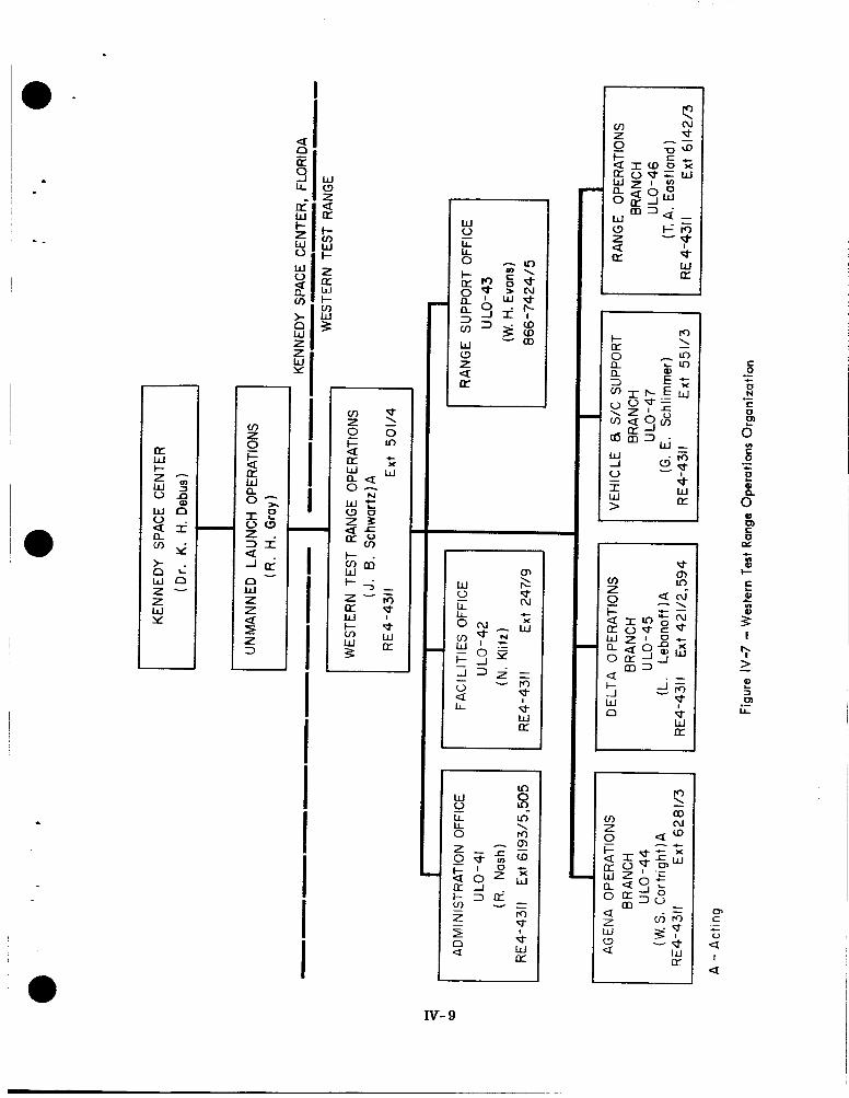
- -
I
.
t - . w cnm
* S 0 .- c E al
0"
c YI
al I- C
0) L
c
2
IV- 9
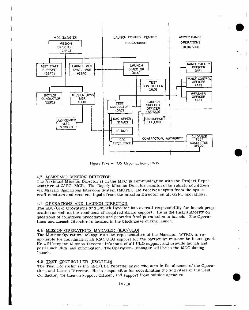
MOC (BLDG 32)
DIRECTOR
SKTEST MISSION OPNS CONDUCTOR MGR
(GSFC) (ULO)
ULO/ CENTER
SUPPORT
I
I
I I I I
I L,,,,
LAUNCH CONTROL CENTER
BLOCKHOUSE
------ DIRECTOR
CONTROLLER HTI r - I
SUPPORT CONDUCTOR OFFICER
I CONTRACTUAL P
-&--------- FIRST STAGE
AFWTR RANGE
OPERATIONS ( BLDG.300 )
RANGESAFETY OFFICER
OFFICER
WEATHER OFFICER
(AF)
Figure IV-8 - TOS Organization a t WTR
4.2 ASSISTANT IMSSION DIRECTOR The Assistant Mission Director is in the MDC in communication with the Project Repre- sentative at GSFC, MCR. The Deputy Mission Director monitors the vehicle countdown via Missile Operations Intercom System (MOPS). He receives inputs f rom the space- craf t monitors and receives inputs f rom the mission Director on all GSFC operations.
4.3 OPERATIONS AND LAUNCH DIRECTOR The KSC/ULO Operations and Launch Director has overall responsibility for launch prep- aration as well as the readiness of required Range support. He is the final authority on questions of countdown procedures and provides final permission to launch. The Opera- tions and Launch Director is located in the blockhouse during launch.
4.4 MISSION OPERATIONS MANAGER (KSC/ULO) The Mission Operations Manager as the representative of the Manager, WTRO, is re- sponsible for coordinating all KSC/ULO support fo r the particular mission he is assigned. He wi l l keep the Mission Director informed of all ULO support and provide launch and postlaunch data and information. The Operations Manager will be in the MDC during launch.
4.5 TEST CONTROLLER (KSC/ULO) The Tes t Controller is the KSC/ULO representative who ac ts in the absence of the Opera- tions and Launch Director. He is responsible fo r coordinating the activities of the Tes t Conductor, the Launch Support Officer, and support f rom outside agencies. 0
IV- 10
4.6 TEST CONDUCTOR (DAC) The DAC Test Conductor is responsible for conducting all Improved Delta readiness tests and countdown in accordance with NASA directives. The Test Conductor is directly responsible to the Operations and Launch Conductor.
4.7 SPACECRAFT COORDINATOR (KSC/ULO) The Spacecraft Coordinator, located in the blockhouse, coordinates spacecraft countdown with all other elements of the launch operation. He relays information and progress re- ports to the MDC and the 0-perations and Launch Director.
4.8 SPACECRAFT SYSTEMS MANAGER The Spacecraft Systems Manager, or his representative, reports the status of the space- . - craft k a MOPS. -He reports problems if they arise and recommends whether to hold or scrub the launch. The Spacecraft Systems Manager or his representative is in the block- house and is in voice communications with MCC and the Test Conductor. A RCA-AED spacecraft representhtive is in the launch support van and reports to MCC via MOPS.
5. LAUNCH COMMUNICATIONS
5.1 WTR RANGE COMMUNICATIONS During the prelaunch tests and launch countdown range communications (Figure IV-9) are provided for use by the Mission Director, spacecraft, launch vehicle, and operations personnel.
Range communications consists of a Missile Operations Intercom System (MOPS) and Voice Direct Lines (VDL). There are eight channels of MOPS available for use during the launch countdown. Four channels are assigned for the booster and second-stage tests and checkout, two channels for spacecraft, one for conduct of the overall count, and one as a KSC engineering net.
The VDL is a private line system programmed on certain consoles connecting key per- sonnel at the MM3, Blockhouse, NASA Telemetry Station, Spacecraft Laboratory, and Range Operations Building. Details of the Range Communications system and operation will be presented in the TOS Operations Summary produced and distributed by KSC two weeks before launch countdown.
5.2 SCAMA SCAMA m a y be used to provide the Mission Director with direct contact with GSFC for communications with the Project Representative in MCR, TEC, and the CDA stations. SCAMA is used as the link for relaying launch status data to OPSCON.
5.3 NASA COMMUNLCATIONS RULES AND COUNTDOWN Figure IV-10 is a block diagram of the NASCOM voice launch communications network. Table IV-1 shows the TEC communications countdown.
When directed by GSPA (at approximately T-50 minutes) all participating stations observe the following rules:
0 All messages must be as brief as possible consistent with clarity
0 Individual message receipts are not sent unless dictated by the message precedence or originators
0 Self-addressed number comparisons a re utilized if no traffic is received for a period not to exceed 10 minutes
Iv-11
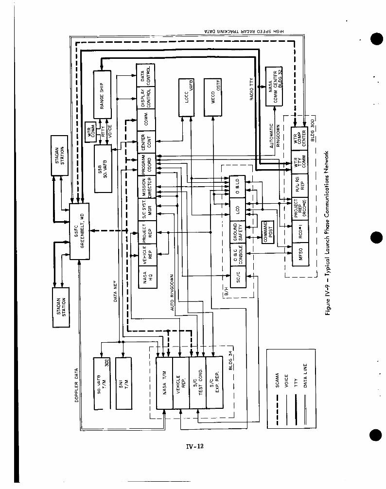
I
+ - I
a I m W
z (3 ,- a a
c w z
5 n
r* I
r+ I k*
J-b
I I I I I I I i I I I I I I I I I
a
I I
I I
I--
I1 I - ,- IV- 12
n dl
I I I I I I I I I I I
a
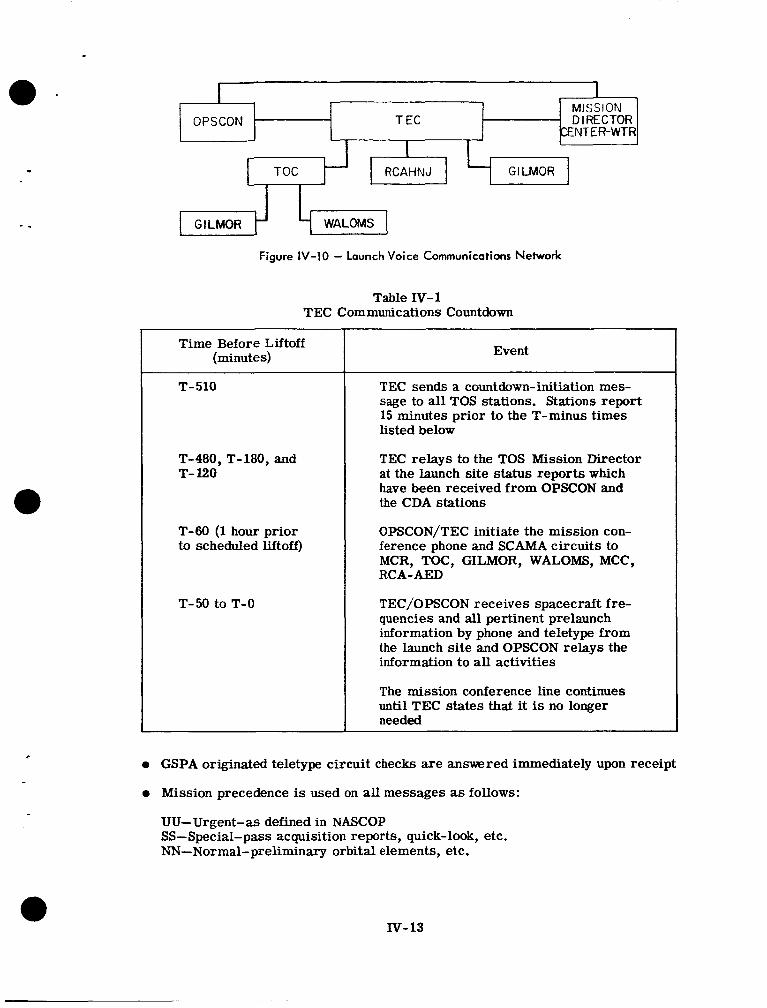
r 1 a - .
c
- OPSCON T EC
I I I 1
I - 7 MISSION OPSCON T EC - DIRECTOR
/ENTER-WTR I I I
Figure IV-10 - Launch Voice Communications Network
Table IV-1 TEC Communications Countdown
Time Before Liftoff (minutes)
T-510
T-480, T-180, and T- 120
T-60 (1 hour prior to scheduled liftoff)
T-50 to T-0
Event
TEC sends a countdown-initiation mes- sage to all TOS stations. Stations report 15 minutes prior to the T-minus times listed below
TEC relays to the TOS Mission Director at the launch site status reports which have been received from OPSCON and the CDA stations
OPSCON/TEC initiate the mission con- ference phone and SCAMA circuits to MCR, TOC, GILMOR, WALOMS, MCC, RCA-AED
TEC/OPSCON receives spacecraft fre- quencies and all pertinent prelaunch information by phone and teletype from the launch site and OPSCON relays the information to all activities
The mission conference line continues until TEC states that it is no longer needed
0 GSPA originated teletype circuit checks are ansuered immediately upon receipt
0 Mission precedence is used on all messages as follows:
UU-Urgent-as defined in NASCOP SS-Special-pass acquisition reports, quick-look, etc. NN-Normal-preliminary orbital elements, etc.
N-13
6. SPACECRAFT AND VEHICLE COUNTDOWN
The countdown events for missions using the Delta vehicle are detailed in the ULO Operations Summary and in the DTO and PRD for the specific mission.
The Test Conductor has overall cognizance of the launch and is responsible for executing the countdown. The countdown is divided into tasks, such as spacecraft preparation, engine checks, electrical system checks, loading of fuel, and loading of liquid oxygen. Each task is assigned to a special crew under the direction of a task leader; several tasks can be accomplished simultaneously. Each task leader must request permission from the Test Conductor before he starts his task, must execute the task in accordance with the Countdown Manual, and must report to the Test Conductor when his task is completed. The task leader must consult the Test Conductor on any problems, and determine a course of action jointly within him.
Tasks involving spacecraft preparation are directed by the Spacecraft Systems Manager, who reports to the Test Conductor. The Spacecraft Systems Manager submits the final spacecraft task events to the Test Conductor prior to R-10 day for integration into the Countdown Manual. Typical R-1 day and R-0 day countdown milestones a r e listed in Tables IV-2 and IV-3.
7. VEHICLE HANDLING
The Improved Delta vehicle will be stored and checked out at the DAC Santa Monica mis- sion checkout a r e a as shown in Figure IV-11. Each stage will be stored until it is com- mitted to a flight. The first and second stages will then be brought to the grid area and placed in a mission-peculiar configuration. Component, subsystem, system, and all sys- tems tests will be conducted on the vehicle to assure i t s flight readiness. Each subsystem will be assembled, tested and certified for flight. Only if anomalies or failures are en- countered will a subsystem be disassembled while on the launch pad. For example, flight BTL 600 missile-borne guidance equipment (MBGE) wil l be installed and checked out at SantaMonica. Figure IV-12 is a typical schedule for vehicle preparation at the launch site. Third- stage/spacecraft assembly and alignment will initially be done at Building 34.
8. SPACECRAFT HANDLING
8.1 SHIPMENT OF SPACECRAFT AND SUPPORT EQUIPMENT The TOS-AVCS spacecraft will be transported from RCA/AED to WTR in an airtight
. -
shipping container pressurized with dry-nitrogen at a positive pressure of approximately 2 psig. The shipping container, including the spacecraft, weighs approximately 900 pounds, and is 58 inches in diameter and 53 inches high. Both the transmitting antenna and the receiving antenna will be removed from the spacecraft and shipped in a separate package. Four spinup rockets will be installed on the spacecraft, but the rocket terminals will be shorted by means of jumper leads before shipment. These leads will remain in place until just before installation of the third-stage fairing.
8.2 SPACECRAFT HANDLING AT BUILDING 34 If the spacecraft is airlifted to Vandenberg Air Force Base (VAFB) ULO will provide a tractor to haul the spacecraft in i ts container to the NASA/ULO spacecraft laboratory in Building 34. The spacecraft assembly areas in Building 34 will be used for the operational checks and tests of the spacecraft. Overhead cranes, forklift trucks, and other power- handling equipment will be provided by NASA. In general, this equipment will be manned by NASA operators. At all times that the spacecraft is moved a t WTR it will be escorted by AFSSD guards.
IV- 14
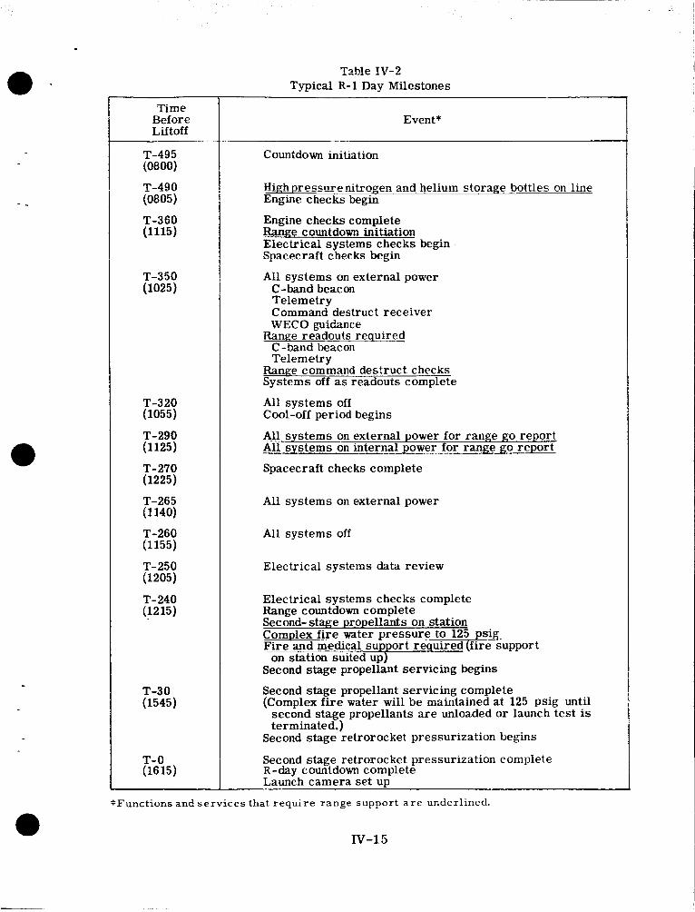
- -
Time Before Liftoff
T-495 (0800)
T-490 (0805)
(1115) T-360
T-350 (1025)
T-320 (1055)
(1 125)
(1225)
(1 140)
(1155)
(1205)
(1215)
T-290
T-270
T-265
T-260
T-250
T-240
T-30 (1545)
T-0 (16 15)
Tzble IV-2 Typical R-1 Day Milestones
Event*
Countdown initiation
High pressure nitrogen m d helium storage bottle: on line Engine checks begin
Engine checks complete Range countdown initiation Electrical systems checks begin Spacerraft checks begin
All systems on external power C -band beacon Telemetry Command destruct receiver WECO guidance
Range readouts required C-band beacon Telemetry
Range command destruct checks Systems off as readouts complete
All s y s t e m s off Cool-off period begins
All systems on external power for range go report All systems on internal power for range go report
Spacecraft checks complete
All systems on external power
All s y s t e m s off
Electrical systems data review
Electrical systems checks complete Range countdown complete Second-stage propellants on station ComDlex fire water pressure to 125 psig Fire-and medical support required (fire support
Second stage propellant servicing begins
Second stage propellant servicing complete (Complex fire water will be maintained at 125 psig until
second stage propellants are unloaded or launch test is terminated.)
Second stage retrorocket pressurization begins
Second stage retrorocket pressurization complete R-day countdown complete Launch camera set UP
on station suited up)
*Functions and services that require range support a r e underlined.
IV-15
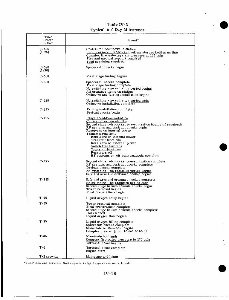
Table IV-3 Typical R - 0 Day Milestones ‘ e
Time Before Liftoff
T-595 (1825)
T-590 (183 0)
T-560
T-500
T-280
T-235
T-205
T- 175
T- 115
T-95
T-55
T-3 5
T-35
T-0
T+2 seconds
Event*
Contractor countdown initiation High pressure nitrogen and helium storage bottles on line Complex fire water system pressure a t 125 psig Fire and medical support required Food servicing required
Spacecraft checks begin
Firs t stage fueling begins
SDacecraft checks comtdete First stage fueling complete No switching - no radiation period begins All ordnance items on station Ordnance and fairing installation begins
No switching - no radiation period ends Ordnance installation complete
Fairing installation complete Payload checks begin
Range countdown initiation Critical Dower on standb Second stage retrorocke2pressurization begins (if required) RF systems and destruct checks begin Receivers on internal power Transm it functions
Receivers on internal power Transmit functions Receivers on external power Switch transmitters Transmit functions Receivers off R F systems on-off when readouts complete
Second stage retrorocket pressurization complete R F systems and destruct checks complete Payload checks complete No switching - no radiation period begins Safe and arm and ordnance hookup begins
Safe and arm and ordnance hookup complete No switching - no radiation period ends Second stage helium console checks begin Tower removal begins Final preparations begin
Liquid oxygen setup begins
Tower removal complete Final preparations complete Second stage helium console checks complete Pad cleared Liquid oxygen flow begins
Liquid oxygen filling complete Spacecraft checks complete 60-minute built-in hold begins Complex cleared (prior to end of hold) 60-minute hold ends Complex fire water pressure to 175 psig Terminal count begins Terminal count complete Engine s ta r t
Mainstage and liftoff
- -
*Functions and services that require-range support a r e underlined.
IV-16
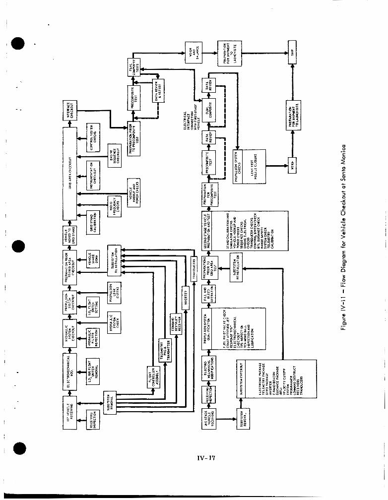
i - '
0 S o v)
+
c 0 + 3 0 Y 0
_t
V
?! m 3
U .-
IV- 17
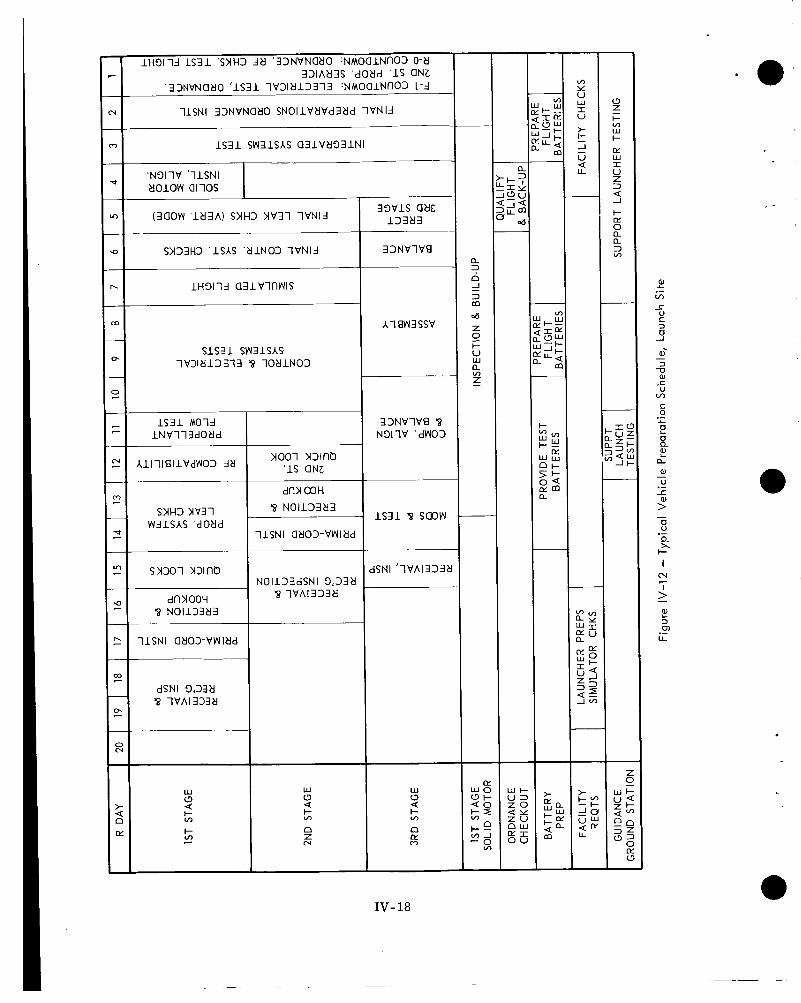
l H 3 1 1 4 LS31 'SYH3 4 8 ' 3 3 N V N a 8 0 : N M O a l N n 0 3 0-8 331h83S ' d O 8 d '1s aNZ
' 3 3NVNa8O 'IS31 l V 3 1 8 1 3 3 1 3 :NMOalNn03 1-3
11SNI 3 3 N V N a 8 0 SNOI lV t fVd38d 1VNIJ
IS31 S W 3 l S A S a 3 l V 8 3 3 1 N I
' N 3 1 l V '11SNI t f o i o w alios
m Y V w I V
> k =' U 4 U
3 3 N V l V B
S l S 3 1 SW31SAS l V 3 1 8 1 3 3 1 3 '8 l O 8 l N 0 3
IS31 M O l J l N V l l 3 d O 8 d
3 3 N V l V B '8 N 3 1 l V 'dW03
A1111811VdW03 Jtl yo01 mino 'IS aNz
dill OOH '8 NO113383
a S Y H ~ mi
W31SAS 'dO8d IS31 '8 smw
11SNI a803-VWl8d
1SNI ' l V h 1 3 3 3 > NO I 1 3 3 dSN I 3'33 ti
'8 l V h 1 3 3 3 8 dnY00H '8 NO113383
11SNI a803-VWlt ld
dSNl 3,338 '8 l V h 1 3 3 3 8
~
w 0 4 I- m
o! n c?
w o 4 5; n Z N
w t - U 3 z o 4 Y z v o ! I o v n w
W o 4 5; 5; -
IV- 18
RCA personnel will unload the spacecraft, prototype model, and all support equipment when it arrives at Building 34 and will move it to the test area. The area will be closed off by all practical means, and only personnel associated with the TOS project will be permitted access.
e -
-.
The launch support van will arrive two weeks before the spacecraft and will be parked alongside Building 34. After launch, the van will bz stored and checkedmt periodicallyby RC4.
8.3 SEPET AND INTERFERENCE TESTS A standard electrical performance test (SEPET) will be conducted. Concurrent with mr- formance of the SEPET, and depending upon availability of support personnel and schedule of events, the prototype m d d will ?x b.s+??ed with a &imixy Lkiid-Siw:e veilicie ai the Spin Test Facility. The third-stage/prototype combination will be taken to the launch pad, using the ground handling fixture. Douglas Aircraft Company (DAC) personnel will be responsible (with RCA assistance) for mating the spacecraft to the third stage.
DAC will perform all subsequent handling and installation of the dummy third-stage/ prototype combination to the second stage of the launch vehicle. When the installation is Completed, RCA will conduct an open-loop transmission test and will support the WTR- directed RF interference tests. When the RF interference tests are completed, the dummy third-stage/prototype combination will be returned to the Spin Test Facility for disas- sembly. No other tests shwald be performed with the prototype model. It will be crated in its shipping container and returned to Building 34. After the launch, RCA will ship it to the RCA/AED facility.
8.4 SPIN TEST FACILITY The spacecraft will be physically turned over to NASA in its shipping container, and transported by NASA truck to the Spin Test Facility.
Upon removal from the shipping container, the spacecraft will be weighed to confirm weight measurements made at RCA/AED before shipment. After the weighing procedures, DAC will mate the spacecraft to the live third-stage vehicle, using standard handling procedures. A weighting ring (approximately 85 pounds) attached to the three hat lugs will provide sufficient force to compress the separation ejection spring. Only personnel immediately concerned u7ith the operations will be permitted in the area; all others will remain in a safe protective area. From the time the spacecraft is mated to the third-stage until launch, the spacecraft will be grounded by means of a grounding lug on the underside of the baseplate.
a
8.5 SERVICE TOWER The third-stage/spacecraft combination will be mated to the second-stage launch vehicle in accordance with standard DAC procedures. The launch pad crane will l if t the space- craft handling fixture off its flat-bed truck and hoist it to the eight level. Another crane will lift the third-stage/spacecraft combination from the eight to the ninth level, and the combination will be mated to the second stage of the launch vehicle. The spacecraft optics will then be uncovered, a visual examination will be made, and the charging plug fed from blockhouse will be installed. The spacecraft will be checked out in accordance with Task IV checkout procedures and cameras will be checked. A special test will determine proper optical focus of the TV cameras. In the optical-focus portion of this test, each TV camera will view a 2-foot square light box mounted on a tripod located at least 5 feet from the edge of the spacecraft. A switch at least 10 feet away will control power to the light box.
The third-stage fairing will be installed after the spacecraft has successfully passed the Task IV checkout and after the spinup rocket mufflers and shorting leads are removed.
Iv-19
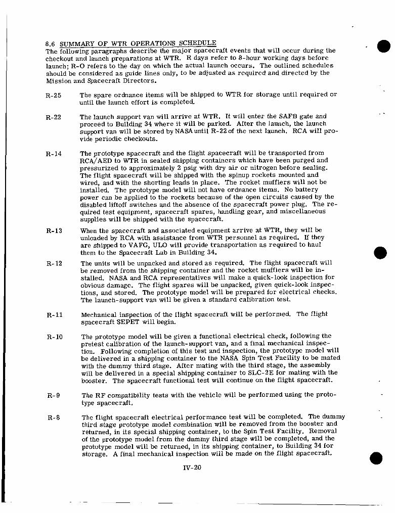
8.6 SUMMARY O F WTR OPERATIONS SCHEDULE The following paragraphs describe the major spacecraft events that will occur during the checkout and launch preparations at WTR. R days refer to 8-hour working days before launch; R - 0 refers to the day on which the actual launch occurs. The outlined schedules should be considered as guide lines only, to be adjusted as required and directed by the Mission and Spacecraft Directors.
R-25
R-22
R- 14
R-13
R- 12
R- 11
R- 10
R- 9
R- 8
The spare ordnance items will be shipped to WTR for storage until required o r until the launch effort is completed.
The launch support van will arr ive at WTR. It will enter the SAFB gate and proceed to Building 34 where it will be parked. After the launch, the launch support van will be stored by NASA until R-22 of the next launch. RCA will pro- vide periodic checkouts.
The prototype spacecraft and the flight spacecraft will be transported from RCA/AED to WTR in sealed shipping containers which have been purged and pressurized to approximately 2 psig with dry air o r nitrogen before sealing. The flight spacecraft wil l be shipped with the spinup rockets mounted and wired, and with the shorting leads in place. The rocket mufflers will not be installed. The prototype model will not have ordnance items. No battery power can be applied to the rockets because of the open circuits caused by the disabled liftoff switches and the absence of the spacecraft power plug. The re- quired test equipment, spacecraft spares, handling gear, and miscellaneous supplies will be shipped with the spacecraft.
When the spacecraft and associated equipment arrive at WTR, they will be unloaded by RCA with assistance from WTR personnel as required. If they are shipped to VAFG, ULO will provide transportation as required to haul them to the Spacecraft Lab in Building 34. The units will be unpacked and stored as required. The flight spacecraft will be removed from the shipping container and the rocket mufflers will be in- stalled. NASA and RCA representatives will make a quick-look inspection for obvious damage. The flight spares will be unpacked, given quick-look inspec- tions, and stored. The prototype model will be prepared for electrical checks. The launch-support van will be given a standard calibration test.
Mechanical inspection of the flight spacecraft will be performed. The flight spacecraft SEPET will begin.
The prototype model will be given a functional electrical check, following the pretest calibration of the launch-support van, and a final mechanical inspec- tion. Following completion of this test and inspection, the prototype model will be delivered in a shipping container to the NASA Spin Test Facility to be mated with the dummy third stage. After mating with the third stage, the assembly will be delivered in a special shipping container to SLC-BE for mating with the booster. The spacecraft functional test will continue on the flight spacecraft.
The R F compatibility tests with the vehicle will be performed using the proto- type spacecraft.
The flight spacecraft electrical performance test will be completed. The dummy third stage prototype model combination will be removed from the booster and returned, in its special shipping container, to the Spin Test Facility. Removal of the prototype model from the dummy third stage will be completed, and the prototype model will be returned, in its shipping container, to Building 34 fo r storage. A final mechanical inspection will be made on the flight spacecraft.
IV-20
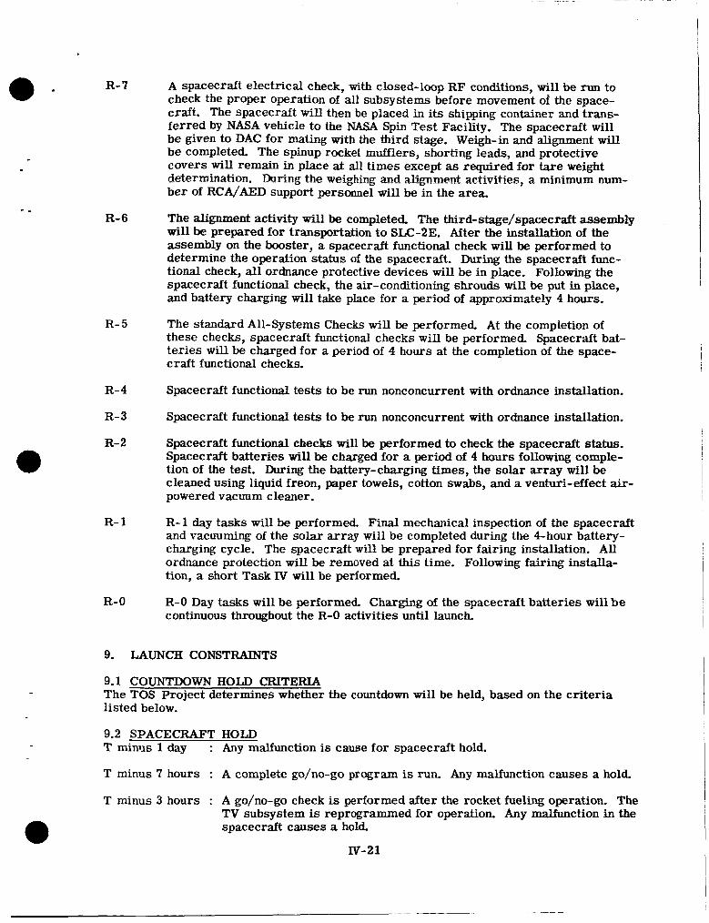
a - -
R- 7
R- 6
R- 5
R- 4
R- 3
R- 2
R- 1
R-0
A spacecraft electrical check, with closed-loop RF conditions, will be run to check the proper operation of all subsystems before movement of the space- craft. The spacecraft will then be placed in its shipping container and trans- ferred by NASA vehicle to the NASA Spin Test Facility. The spacecraft will be given to DAC for mating with the third stage. Weigh-in and alignment will be completed. The spinup rocket mufflers, shorting leads, and protective covers will remain in place at all times except as required for tare weight determination. During the weighing and alignment activities, a minimum num- ber of RCA/AED support personnel will be in the area.
The alignment activity will be completed. The third-stage/spacecraft assembly will be prepared for transportation to SLC-2E. After the installation of the assembly on the booster, a spacecraft functional check will be performed to determine the operation status of the spacecraft. During the spacecraft func- tional check, all ordnance protective devices will be in place. Following the spacecraft functional check, the air-conditioning shrouds w i l l be put in place, and battery charging will take place for a period of approximately 4 hours.
The standard All-Systems Checks will be performed. At the completion of these checks, spacecraft functional checks will be performed. Spacecraft bat- teries will be charged for a period of 4 hours at the completion of the space- craft functional checks.
Spacecraft functional tests to be run nonconcurrent with ordnance installation.
Spacecraft functional tests to be run nonconcurrent with ordnance installation.
Spacecraft functional checks will be performed to check the spacecraft status. Spacecraft batteries will be charged for a period of 4 hours following comple- tion of the test. During the battery-charging times, the solar array will be cleaned using liquid freon, paper towels, cotton swabs, and a venturi-effect air- powered vacuum cleaner.
R-1 day tasks will be performed. Final mechanical inspection of the spacecraft and vacuuming of the solar array will be completed during the &hour battery- charging cycle. The spacecraft wil l be prepared for fairing installation. All ordnance protection will be removed at this time. Following fairing installa- tion, a short Task IV will be performed.
R-0 Day tasks will be performed. Charging of the spacecraft batteries will be continuous throughout the R-0 activities until launch.
9. LAUNCH CONSTRAINTS
9.1 COUNTDOWN HOLD CRITERIA The TOS Project determines whether the countdown will be held, based on the criteria listed below.
9.2 SPACECRAFT HOLD T miniis 1 day : Any malfunction is cause for spacecraft hold.
T minus 7 hours : A complete go/no-go program is run. Any malfunction causes a hold.
T minus 3 hours : A go/no-go check is performed after the rocket fueling operation. The TV subsystem is reprogrammed for operation. Any malfunction in the spacecraft causes a hold.
Iv-21
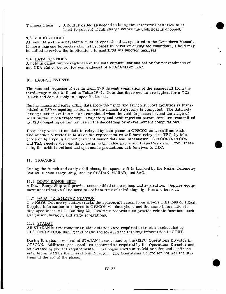
T minus 1 hour : A hold is called as needed to bring the spacecraft batteries to at least 90 percent of full charge before the umbilical is dropped.
9.3 VEHICLE HOLD All vehicle in-line subsystems must be operational as specified in the Countdown Manual. If more than one telemetry channel becomes inoperative during the countdown, a hold may be called to review the implications to postflight malfunction analysis.
9.4 DATA STATIONS A hold is called for nonreadiness of the data communications net or for nonreadiness of any CDA station but not for nonreadiness of RCA/AED o r TOC.
10. LAUNCH EVENTS
The nominal sequence of events from T-0 through separation of the spacecraft from the third-stage motor is listed in Table IV-4. Note that these events are typical for a TOS launch and do not apply to a specific launch.
During launch and early orbit, data from the range and launch support facilities is trans- mitted to DSD computing center where the launch trajectory is computed. The data col- lecting functions of this net a r e completed when the vehicle passes beyond the range of WTR on the launch trajectory. Trajectory and orbit injection parameters a r e transmitted to DSD computing center for use in the succeeding orbit-refinement computations.
Frequency versus time data is relayed by data phone to OPSCON on a realtime basis. The Mission Director in MDC o r his representative will have relayed to TEC, by tele- phone o r teletype, all other pertinent launch data and information. OPSCON/NETCON and TEC receive the results of initial orbit calculations and trajectory data. From these data, the orbit is refined and ephemeris predictions will be given to TEC.
11. TRACKING
During the launch and early orbit phase, the spacecraft is tracked by the NASA Telemetry Station, a down range ship, and by STADAN, NORAD, and SAO.
11.1 DOWN RANGE SHIP A Down Range Ship will provide second/third stage spinup and separation. Doppler equip- ment aboard ship will b e used to confirm time of third stage ignition and burnout.
- -
11.2 NASA TELEMETRY STATION The NASA Telemetry station tracks the spacecraft signal from lift-o€f until loss of signal. Doppler information is relayed to OPSCON via data phone and t h e same information is displayed in the MDC, Building 32. Realtime records also provide vehicle functions such as ignition, burnout, and stage separations.
11.3 STADAN All STADAN interferometer tracking stations are required to track as scheduled by OPSCON/NETCON during this phase and forward the tracking information to GPUT.
During this phase, control of STADAN is exercised by the GSFC Operations Director in OPSCON. Additional personnel a r e appointed as required by the Operations Director and as dictated by project requirements. This phase s tar ts at T-240 minutes and continues unt i l terminated by the Operations Director. The Operations Controller notifies the sta- tions at the end of the phase.
IV-22
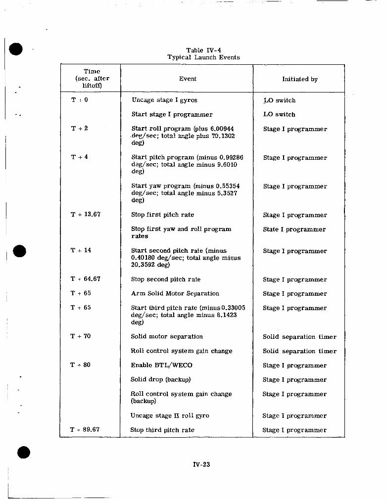
0 -
*
- .
~
a
I C
Time (sec. after
liftoff)
T + O
T + 2
T + 4
T + 13.67
T + 14
T + 64.67
T + 65
T + 65
T + 70
T + 80
T + 89.67
Table N - 4 Typical Launch Events
Start stage I programmer
Start roll program (plus 6.00944 .deg/sec; btd mg?e p k s 70.1302 deg)
Start pitch program (minus 0.99286 deg/sec; total angle minus 9.6010 deg)
Start yaw program (minus 0.55354 deg/sec; total angle minus 5.3527 deg)
Stop first pitch rate
Stop first yaw and roll program rates
Start second pitch rate (minus 0.40180 deg/sec; total angle minus 20.3592 deg)
Stop second pitch rate
Arm Solid Motor Separation
Start third pitch rate (minusO.33005 deg/sec; total angle minus 8.1423 deg)
Solid motor separation
Roll control system gain change
Enable BTL/wECO
Solid drop (backup)
Roll control system gain change (backup)
Uncage stage II roll gyro
Stop third pitch rate
Initiated by
-50 switch
LO switch
Stage I programmer
Stage I programmer
Stage I programmer
Stage 1 programmer
State I programmer
Stage I programmer
Stage I programmer
Stage I programmer
Stage I programmer
Solid separation timer
Solid separation timer
Stage I programmer
Stage I programmer
Stage I programmer
Stage I programmer
Stage I programmer
IV-23
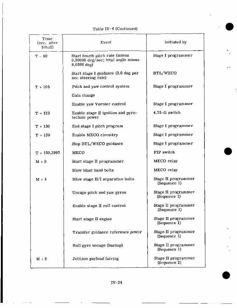
Tinie (sec. after
lift off)
T + 105
T + 123
T + 130
T + 139
T + 150.2997
M + O
M + 4
M + 8
Table IV-4 (Continued)
Event
Start fourth pitch rate (minus 0.20090 deg/sec; total angle minus 8.0360 deg)
Start stage I guidance (3.0 deg per sec steering rate)
Pitch and yaw control system
Gain change
Enable yaw Vernier control
Enable stage 11 ignition and pyro- technic power
End stage I pitch program
Enable MECO circuitry
Stop BTL/WECO guidance
MECO
Start stage I1 programmer
Blow blast band bolts
Blow stage II/I separation bolts
Uncage pitch and yaw gyros
Enable stage II. roll control
Start stage I1 engine
Transfer guidance reference power
Roll gyro uncage (backup)
Jettison payload fairing
Initiated by
Stage I programmer
BTL/WECO
Stage I programmer
Stage I programmer
4.75-G switch
Stage I programmer
Stage I programmer
Stage I programmer
FIP switch
MECO relay
MECO relay
Stage I1 programmer (Sequence 1)
Stage I1 programmer (Sequence 1)
Stage 11 programmer (Sequence 1)
Stage I1 programmer (Sequence 1)
Stage I1 programmer (Sequence 1)
Stage I1 programmer (Sequence 1)
Stage I1 programmer (Sequence 2)
IV-24
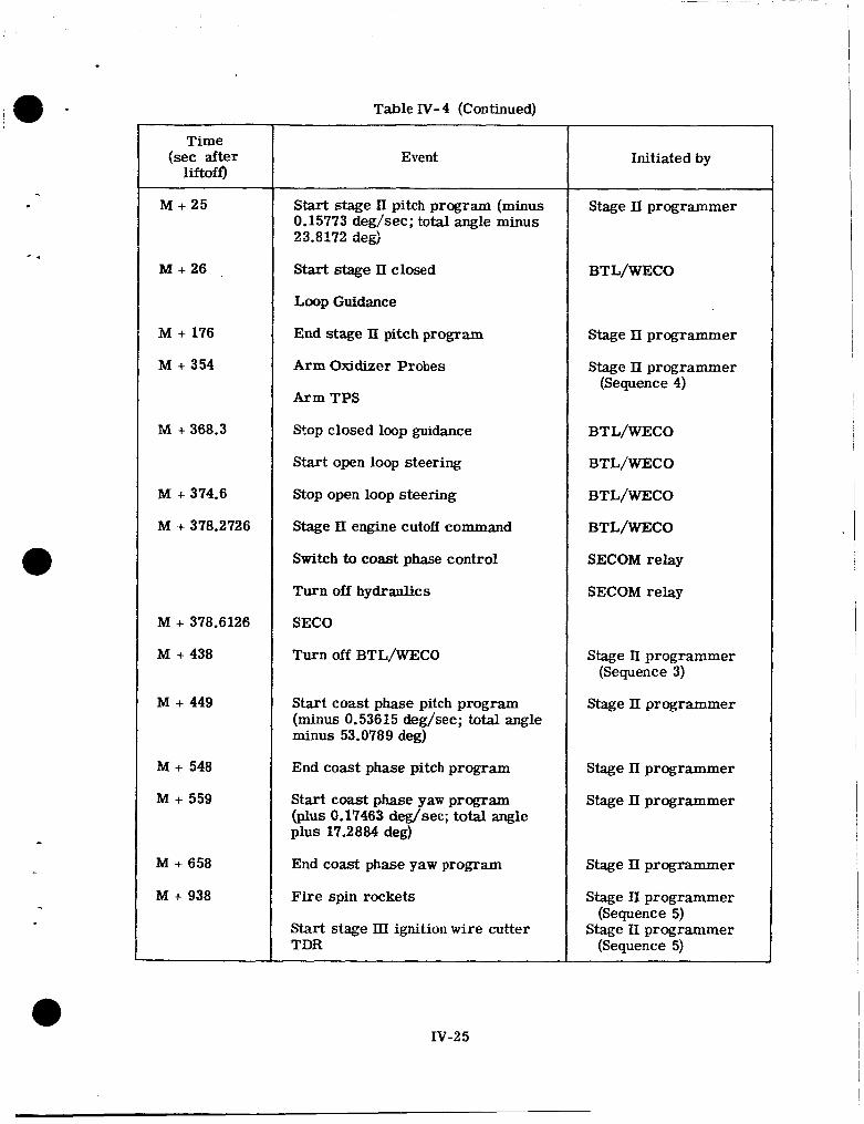
Table IV-4 (Continued)
Time (sec after
liftoff)
M + 25
M + 26
M + im M i 354
M + 368.3
M + 374.6
M i 378.2726
M + 378.6126
M + 438
M + 449
M + 548
M i- 559
M i 658
M + 938
Event
~ ~~
Start stage II pitch program (minus 0.15773 deg/sec; total angle minus 23.8172 deg)
Start stage 11 closed
Loop Guidance
End stage II pitch program
Arm Oxidizer Probes
Arm TPS
Stop closed loop guidance
Start open loop steering
Stop open loop steering
Stage 11 engine cutoff command
Switch to coast phase control
Turn off hydraulics
SECO
Turn off BTL/WECO
Start coast phase pitch program (minus 0.53615 deg/sec; total angle minus 53.0789 deg)
End coast phase pitch program
Start coast phase yaw program (plus 0.17463 deg/sec; total angle plus 17.2884 deg)
End coast phase yaw program
Fire spin rockets
Start stage IIX ignition w i r e cutter TDR
Initiated by
Stage II programmer
BTL/WECO
Stage 11 programmer
Stage 11 programmer (Sequence 4)
BTL/WECO
BTL/WECO
BTL/WECO
BTL/WECO
SECOM relay
SECOM relay
Stage 11 programmer (Sequence 3)
Stage 11 programmer
Stage 11 programmer
Stage 11 programmer
Stage 11 programmer
Stage II programmer
Stage 11 programmer (Sequence 5)
(Sequence 5)
IV-2 5
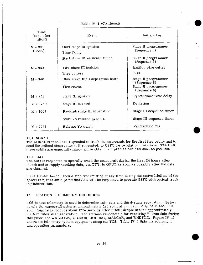
Table IV-4 (Continued)
Time (sec. after
liftoff)
M + 938 (Cont .)
M + 939
M + 940
M + 953
M + 975.5
M + 1064
M + 1066
Event
Start stage 111 ignition
Time Delay
Start Stage III sequence timer
Fire stage 111 ignition
Wire cutters
Blow stage III/II separation bolts
Fire retros
Stage I11 ignition
Stage I11 burnout
Payload/stage I11 separation
Start Yo release pyro TD
Release Yo weight
Initiated by
Stage II programmer (Sequence 5)
Stage 11 programmer
Ignition wire cutter
TDR
Stage TI programmer
Stage II programmer
Pyrotechnic time delay
Depletion
Stage 111 sequence timer
Stage 111 sequence timer
Pyrotechnic TD
(Sequence 5)
(Sequence 6)
(Sequence 6)
11.4 NORAD The NORAD stations a r e requested to track the spacecraft for the first five orbits and to send the refined observations, if requested, to GSFC for orbital computations. The f i rs t three orbits are especially important in obtaining a precise orbit as soon as possible.
11.5 SAO The SA0 is requested to optically track the spacecraft during the first 24 hours after launch and to supply tracking data, via TTY, to GPUT as soon as possible after the data a r e obtained.
If the 136-Mc beacon should stop transmitting at any time during the active lifetime of the spacecraft, i t is anticipated that SA0 will be requested to provide GSFC with optical track- ing information.
12. STATION TELEMETRY RECORDING
TOS beacon telemetry is used to determine spin rate and third-stage separation. Before despin the spacecraft spins at approximately 126 rpm; after despin it spins at about 10 rpm. Separation occurs about 1274 seconds after liftoff; despin occurs approximately 9 i. 5 minutes after separation. The stations responsible for receiving V-scan data during this phase are WALCOMS, GILMOR, JOBURG, MADGAR, and WNKFLD. Figure 1V-13 shows the telemetry system equipment setup fo r TOS. Table IV-5 lists the equipment and operating parameters.
IV-26
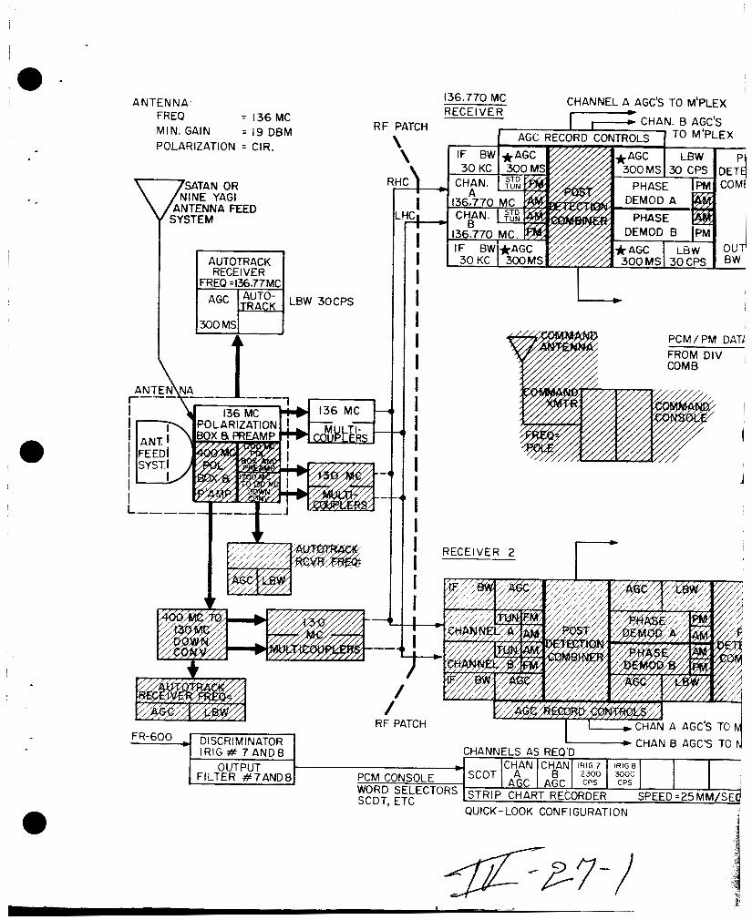
I .
A NTEN N A: FREO = 136MC MIN. GAIN = 19 DBM POLARIZATION = ClR.
SATAN OR NINE YAGI
ANTENNA FEED Q SYSTEM
I AUTOTRACK RECEIVER
FREQ =136.77MC
LB W 30 CPS
CHANNEL A AGC'S TO M'PLEX 136.770 MC RECEIVER
RF PATCH
*
FR-600 J DISCRIMINATOR 1
I I I I I I 1 I I I I I I I I I I I I
PCM/PM DATC FROM DIV ~
I
1 I i
I- RECEIVER 2
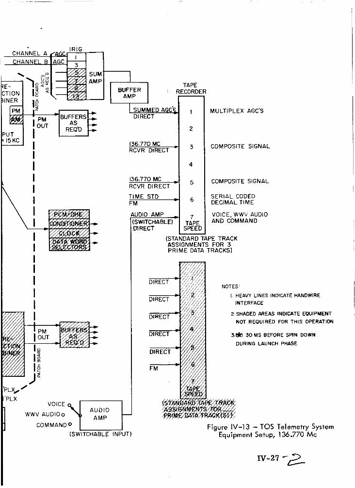
UT I5 KC
I I
Q I
I I I I I I
I SUMMED A G C ~ DIRECT
136.770 MC RCVR DIRECT '
TAPE RECORDER
PLX
AUDIO VOICE
W W V AUDlOo
136.770 MC RCVR DIRECT
m
TIME STD FM
COMMANDO I I (SWITCHABLE INPUT)
JDIO AMP , SWITCHABLE) nRECT
(STL AS! PR
I
2
3
4
5
6
7 TAPE SPEED
DARD SNMEN' IE DATC
MULTIPLEX AGC'S
COMPOSITE SIGNAL
COMPOSITE SIGNAL
SERIAL CODED DECIMAL TIME
VOICE, WWV AUDIO AND COMMAND
,PE TRACK ; FOR 3 TRACKS)
1 HEAVY LINES INDICATE HANDWIRE INTERFACE
2 SHADED AREAS INDICATE EOUIPMENT NOT REQUIRED FOR THIS OPERATION
3.tjr) 30 MS BEFORE SPIN DOWN
DURING LAUNCH PHASE
Figure I\ - - 3 - TOS Telemetry System tquipment Setup, 136.770.MC
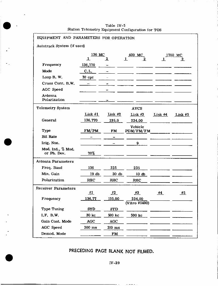
Table IV-5 Station Telemetry Equipment Configuration for TOS
EQUIPMENT AND PARAMETERS FOR OPERATION
Autotrack System (if used)
136 MC 2 - 1 -
400 MC - 1 - 2
1700 MC 2 - 1 -
Frequency 136,770 - Mode C.L. - h o p €3. w. m CFE ~
Cross Corr. B.W. - - AGC Speed - Antenna Polarization -
AVCS
Link #1 Link #2 Link #3 Link# Link#5
Telemetry System
General 136.770 235.0 234.00 Vehicle
Type FM/PM FM PDM/FM/FM Bit Rate - - Irig. Nos. - Mod Ind., % Mod.
Antenna Parameters
9
or Ph. Dev. 70%
Freq. Band 136 235 235
Min. Gain 19 db 30 db 10 db
Polarization RfIC RHC RHC
Receiver Parameters - #1 #2 #3 #4 #5
Frequency 136.77 135.00 234.00
Type Tuning STD STD
I.F. B.W. 30 kc 500 kc 500 kc Gain Cont. Mode AGC AGC
AGC Speed 300 ms 300 m s
Demod. Mode FM
(Vitro #1400)
PRECEDING PAGE BLANK NOT FILMED.
IV-2 9
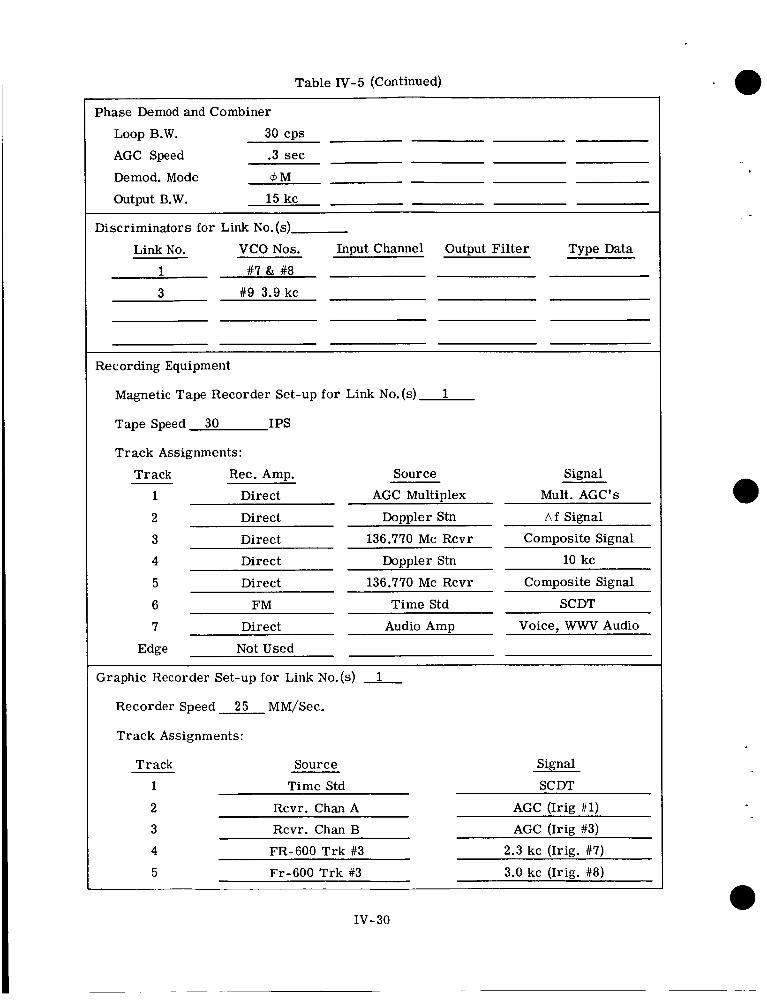
Table IV-5 (Continued)
1 #7 & #8 I
Phase Demod and Combiner
Loop B.W. 30 cps
AGC Speed .3 sec
Demod. Mode 4M
Output B.W. 15 kc
Link No. VCO Nos. Input Channel Output Filter Type Data 1 #7 & #8 3 #9 3.9 kc 3 #9 3.9 kc
Recording Equipment
Magnetic Tape Recorder Set-up for Link No.(s) 1
Tape Speed 30 IPS
Track Assignments:
Track Rec. Amp.
Direct
Direct
Direct
Direct
Source
AGC MultiDlex
Doppler Stn
136.770 Mc Rcvr
Doppler Stn
Direct
F M
136.770 Mc Rcvr
Time Std
Direct Audio Amp
Signal
Mult. AGC's
a f Signal
ComDosite Signal I
10 kc
ComDosite Signal
SCDT
Voice. WWV Audio
Edge Not Used I ~~ ~
Set-up for Link No.(s) 1
I Recorder Speed 25 MM/Sec.
I Track Assignments:
Track Source Signal
1 Time Std SCDT
2 Rcvr. Chan A AGC (Irig #1) 3 Rcvr. Chan B AGC (Irig #3)
4 FR-600 Trk #3 2.3 kc (Irig. #7)
5 Fr-600 Trk #3 3.0 kc (Irig. #8)
IV- 30
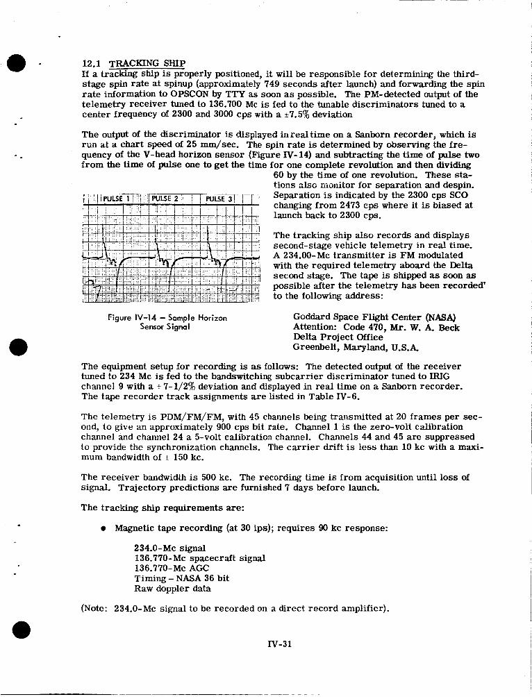
12.1 TRACKING SHIP If a tracking ship is properly positioned, it will be responsible for determining the third- stage spin rate at spinup (approximately 749 seconds after launch) and forwarding the spin rate information to OPSCON by TTY as soon as possible. The PM-detected output of the telemetry receiver tuned to 136.700 Mc is fed to the tunable discriminators tuned to a center frequency of 2300 and 3000 cps w i t h a *7.5% deviation
The output of the discriminator is displayed in red time on a Sanborn recorder, which is ~ I I at a chart speed of 25 mm/sec. The spin rate is determined by observing the fre- quency of the V-head horizon sensor (Figure N-14) and subtracting the time of pulse two from the time of pulse one to get the time for one complete revolution and then dividing
60 by the time of one revolution. These sta- t i m ~ absc iiiciriitor for separation and despin. Separation is indicated by the 2300 cps SCO changing from 2473 cps where it is biased at launch back to 2300 cps.
The tracking ship also records and displays second-stage vehicle telemetry in real time. A 234.00-Mc transmitter is FM modulated with the required telemetry aboard the Delta second stage. The tape is shipped as soon as possible after the telemetry has been recorded' to the following address:
Figure IV-14 - Sample Horizon Sensor Signal
Goddard Space Flight Center (NASA) Attention: Code 470, Mr. W. A. Beck Delta Project Office Greenbelt, Maryland, U.S.A
The equipment setup for recording is as follows: The detected output of the receiver tuned to 234 Mc is fed to the bandswitching subcarrier discriminator tuned to IEUG channel 9 with a rt 7-1/2% deviation and displayed in real time on a Sanborn recorder. The tape recorder track assignments a re listed in Table IV-6.
The telemetry is PDM/FM/FM, with 45 channels being transmitted at 20 frames per sec- ond, to give an approximately 900 cps bit rate. Channel 1 is the zero-volt calibration channel and channel 24 a 5-volt calibration channel. Channels 44 and 45 are suppressed to provide the synchronization channels. The carrier drift is less than 10 kc with a maxi- mum bandwidth of c 150 kc.
The receiver bandwidth is 500 kc. The recording time is from acquisition until loss of signal. Trajectory predictions are furnished 7 days before launch
The tracking ship requirements are:
e Magnetic tape recording (at 30 ips); requires 90 kc response:
234.0-MC signal
136.770-MC AGC 136.770-Mc spacecraft signal
Timing - NASA 36 bit Raw doppler data
(Note: 234.0-Mc signal to be recorded on a direct record amplifier).
IV-31
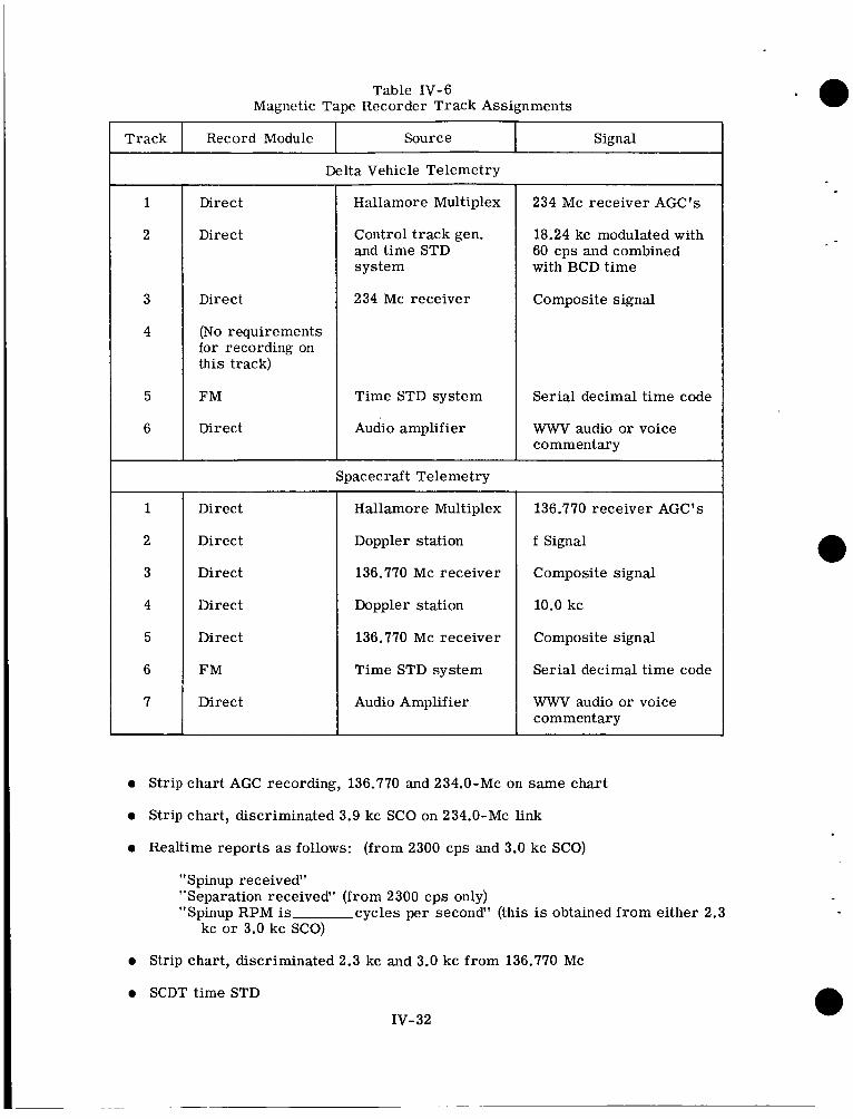
Track Record Module Source
Direct
Signal
Direct
Direct
(No requirements for recording on this track)
FM
Direct
Direct
Direct
Direct
Direct
Direct
F M
Direct
Hallamore Multiplex
Control track gen. and time STD system
234 Mc receiver
Time STD system
Audio amplifier
Spacecraft Telemetry
Hallamore Multiplex
Doppler station
136.770 Mc receiver
Doppler station
136.770 Mc receiver
Time STD system
Audio Amplifier
234 Mc receiver AGC's
18.24 kc modulated with 60 cps and combined with BCD time
Composite signal
Serial decimal time code
WWV audio or voice commentary
136.770 receiver AGC's
f Signal
Composite signal
10.0 kc
Composite signal
Serial decimal time code
WWV audio or voice commentary
0 Strip chart AGC recording, 136.770 and 234.0-Mc on same chart
0 Strip chart, discriminated 3.9 kc SCO on 234.0-Mc link
0 Realtime reports as follows: (from 2300 cps and 3.0 kc SCO)
"Spinup received" "Separation received" (from 2300 cps only) "Spinup RPM is cycles per second" (this is obtained from either 2.3
kc or 3.0 kc SCO)
0 Strip chart, discriminated 2.3 kc and 3.0 kc from 136.770 Mc
0 SCDT time STD
IV- 32
a -
-
The vehicle tapes are to be shipped to:
Unmanned Launch Operations P.O. Box 186, Cape Canaveral, Florida U.S.A. Attention: A. J. Mackey
Copies are provided TEC as soon as possible. The realtime reports are made to hangar AE, Cape Kennedy (GCPN) and OPSCON (GOPS) via existing cpmmunications means.
The following is a description of the data to be read, and how to read it.
In order to assist in the determination of success or failure of a mission, and to assist in prediction of preliminary orbital parameters, the verification and time of Occurrence of third-stage spinup and separation are desired. This data is displayed on the IRIG channel 9 (3.9 kc) on the second-stage telemetry system (234.0 Mc). The data is re- corder on magnetic tape and on a direct-write recorder for immediate readout by ship personnel.
Four items of information a re desired: occurrence of the events; time of spinup indi- cation; time of separation indication; and spinup RPM.
These times of spinup and separation are reported as accurately as possible, but at least to within f 1 second (preferably 0.1 second) in Zulu time. Any realtime recordings run for this purpose are not stopped, but continue to run to preclude any possiblilty of stopping on an erroneous indication and missing the real events. Expected wave shapes are shown in Figure lV-15.
At spinup, which occurs at Time A, the voltage level increases from 40% to 95%, and begins cycling at approximately 6 cps. The elapsed time from A to B is 2 seconds. Actual separation occurs at time B, at which time the rate of cycling abruptly decreases and continues to slow down. At time C the cycling stops, and the channel may come to rest at either a 40% or 95% level. This level is not measured. Prior to the spinup time this channel has other steps, all of which are complete by SECO + 1 second. These other events are not reported.
There should be a small loss of signal, 0.3 seconds duration, at spinup + 6 seconds. This is stage-three ignition, and may be reported i f observed, but only as a drop in AGC-not as a confirmed ignition event.
Spinup RPM is measured during the time interval from D to B. In this example it is 2.5 cycles per second. It may vary from 2 cycles per second to 6 cycles per second. Exactly 1 second of time is not required, but only this portion of the wavetrain is used. Spin rate can be determined by counting the number of cycles to the nearest tenth, from D to B (1 second interval) to obtain cycles per second. Then spin rate (RPM) equals CPS divided by 2, multiplied by 60.
12.2 JOBURG, MADGAR, AND WINKFIELD JOBURG. MADGAR. and WINKFIELD are responsible for determining if separation and despin did occur. Procedures for determining separation are as follows:
-
The normal 2300-cps subcarrier, which phase modulates the 136.770-Mc beacon with V-head horizon sensor information, is biased to 2473 cps from launch until separation of the spacecraft from the third stage. At separation, the bias is removed and the subcarrier frequency returns to 2300 cps.
IV- 33
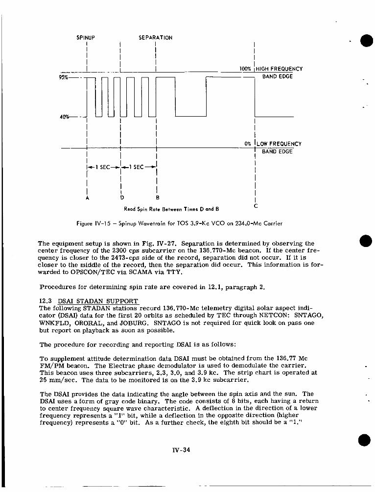
SPINUP SEPARATION
95% -
40%-
--
1' I I I I I I 0% !LOW FREQUENCY I I I BAND EDGE
I I I I I I
I I I I
I
I I I
I I c l S E C - c l SEC-
I I A D 0
C Read Spin Rate Between Times D and B
Figure IV-15 - Spinup Wavetrain for TOS 3.9-Kc VCO on 234.0-Mc Carrier
The equipment setup is shown in Fig. W-27. Separation is determined by observing the center frequency of the 2300 cps subcarrier on the 136.770-Mc beacon. If the center fre- quency is closer to the 2473-cps side of the record, separation did not occur. If it is closer to the middle of the record, then the separation did occur. This information is for- warded to OPSCON/TEC via SCAMA via TTY.
Procedures for determining spin rate are covered in 12.1, paragraph 2.
12.3 DSAI STADAN SUPPORT The following STADAN stations record 136.770-Mc telemetry digital solar aspect indi- cator (DSAI) data for the first 20 orbits as scheduled by TEC through NETCON: SNTAGO, WNKFLD, ORORAL, and JOBURG. SNTAGO is not required for quick look on pass one but report on playback as soon as possible.
The procedure for recording and reporting DSAI is as follows:
To supplement attitude determination data DSAI must be obtained from the 136.77 Mc FM/PM beacon. The Electrac phase demodulator is used to demodulate the carrier. This beacon uses three subcarriers, 2.3, 3.0, and 3.9 kc. The s t r ip chart is operated at 25 mm/sec. The data to be monitored is on the 3.9 kc subcarrier.
The DSAI provides the data indicating the angle between the spin axis and the sun. The DSAI uses a form of gray code binary. The code consists of 8 bits, each having a return to center frequency square wave characteristic. A deflection in the direction of a lower frequency represents a 11111 bit, while a deflection in the opposite direction (higher frequency) represents a "0" bit. As a further check, the eighth bit should be a "1."
IV-34
Before dcspin the DSAI code is unusable. After despin the DSAI rode i s repeated every 5 to 6 seconds.
The data i s reported to GOPS GOSI as ;I series of "ones" (1's) and "zeroes'' (0's) along with the time at which thc reading w a s made. For exmiple: 1129202, 11100111. Six consecutive readings are to be reported. It is possible Cor various types of data to be transmitted on the 3.9 kc SCO, so it is important to look only for data in t h e fnrm of &bit rctiirn 'cii center Prequelicy format. If no data of this type is received, GOPS and GOSI should be notified after the pass is completed.
All DSAI quick-look data is teletyped to GOPS and GOSI immediately after the pass is completed.
13. CDA STATION ACTIVITIES
The CDA stations are r e spns ib l e for acquisition, commanding and disseminating the TOS spacecraft data. The stations are Wallops Station, Virginia (WALOMS) and at Fairbanks, Alaska (GILMOR). During the launch and checkout phase, commands <en- crated by TEC and relayed through TOC are received a t the stations and used for space- cr'aft command as described i n Appendix D. Activities during the opcrational phase are covered under NESC SOP'S.
13.1 HANDLING OF SPACECRAFT DATA All data transmitted from the satellite during the pass over the CDA station is recorded 011 a tape recorder. This will be the station tape. When AVCS video data are received a second tape recorder also records the video data.
Telemetry data from the 136.770-Mc beacon is recorded on Brush record charts and both magnetic tape recorders. Extracts of these recordings are teletyped to TOC/TEC if di- rected by TOC. Telemetry is transmitted to TOC/TEC in real time and also with video signals over the broadband line in slightly delayed time. Daily and prepass telemetry calibrations are performed, using the procedures established in the Prelaunch Opera- tional Analysis Handbook. The paper tapes and magnetic tapes are mailed to TOC as directed by TOC.
The AVCS video data i s played over the broadband link to DAPAF as directed by TOC.
All recorded data is properly marked and held for degaussing, destruction, o r mailing as instructed by TOC.
During the checkout phase, Polaroid pictures are made as specified by TOC. Rem'arks will be made on the pass summary describing the quality of these polaroids, which may be destroyed aiter completion of the report.
13.2 STATION EVENTS Each CDA station has a 20-channel events recorder that monitors station performance and some of the spacecraft responses to CDA command. T h e events recorder is used for postpass reconstruction of the type and timing of commands sent and data received. The events recorder data includes:
0 GMT time markers
0 Command modes used during the pass
0 TV and other signal occurrence and loss
xv-35
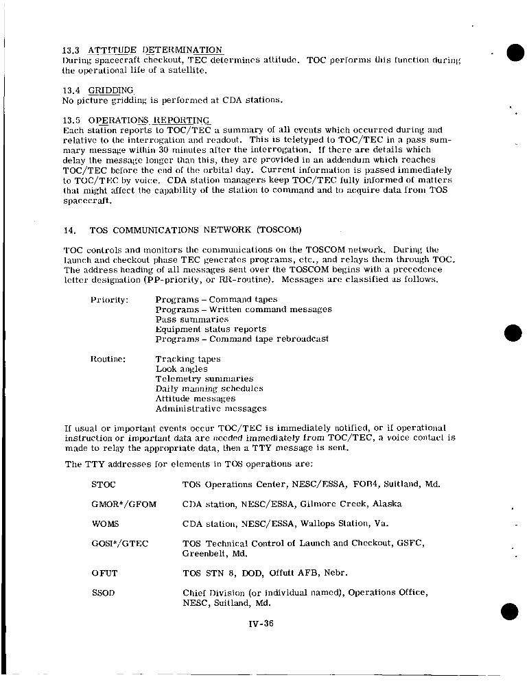
13.3 ATTITUDE DETERMINATION During spacecraft checkout, TEC determines attitude. TOC performs this function during the operational life of a satellite.
13.4 GRIDDING No picture gridding is performed at CDA stations.
13.5 OPERATION& REPORTING Each station reports to TOC/TEC a summary of all events which occurred during and relative to the interrogation and readout. This is teletyped to TOC/TEC in a pass sum- mary message within 30 minutes after the interrogation. If there are details which delay the message longer than this, they are provided in an addendum which reaches TOC/TEC before the end of the orbital day. Current information is passed immediately to TOC/TEC by voice. CDA station managers keep TOC/TEC fully informed of mat te rs that might affect the capability of the station to command and to acquire data f rom TOS spacecraft.
14. TOS COMMUNICATIONS NETWORK (TOSCOM)
TOC controls and monitors the communications on the TOSCOM network. During the launch and checkout phase TEC generates programs, etc., and relays them through TOC. The address heading of all messages sent over the TOSCOM begins with a precedence letter designation (PP-priority, o r RR-routine). Messages are classified as follows.
Priority: Programs - Command tapes Programs - Written command messages P a s s summaries Equipment status reports Programs - Command tape rebroadcast
Routine : Tracking tapes Look angles Telemetry summaries Daily manning schedules Attitude messages Administrative messages
If usual or important events occur TOC/TEC is immediately notified, o r i f operational instruction o r important data are needed immediately f rom TOC/TEC, a voice contact is made to relay the appropriate data, then a TTY message is sent.
The TTY addresses for elements in TOS operations are:
STOC
GMOR*/GFOM
WOMS
GOSI*/GTEC
TOS Operations Center, NESC/ESSA, FOB4, Suitland, Md.
CDA station, NESC/ESSA, Gilmore Creek, Alaska
CDA station, NESC/ESSA, Wallops Station, Va.
TOS Technical Control of Launch and Checkout, GSFC, Greenbelt, Md.
TOS STN 8, DOD, Offutt AFB, Nebr.
Chief Division (or individual named), Operations Office, NESC, Suitland, Md.
0 FUT
SSOD
IV-36
15. TOS APT STATIONS
The APT stations designated by TEC forward the APT Pass Summary and Evaluation Report to TEC. The GSFC controlled stations send a selection of APT pictures, not to exceed six, to TEC for each calendar day. These pictures include all categories pos- sible: best, worst, noisy, etc. Each picture carries the readout time, or number, and other special comments and circumstances which existed. The operating conditions a re also indicated. GILMOR is requested to provide pictures which include the terminator. A f a r east station, to be specified by TEC, will be included to determine the quality of pictures at locations not operating under close NASA or ESSA direction.
Table N-7 is the format of the APT Pass Summary and Evaluation Report.
*Denotes stations in GSFC NASCOM network, all others are in NESC/TOSCOM network.
IV-37
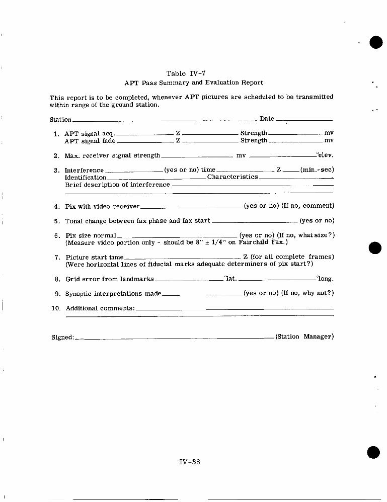
Table IV-7 APT Pass Summary and Evaluation Report
This report is to be completed, whenever APT pictures are scheduled to be transmitted within range of the ground station.
Station Date
1. APT signal acq. Z Strength mv APT signal fade Z Strength mv
2. Max. receiver signal strength mv "elev.
3. Interference (yes o r no) time- Z - (min.- sec) Identificationh Characteristics. Brief description of interference -
4. Pix with video receiver (yes o r no) (If no, comment)
5. Tonal change between fax phase and fax start
6. Pix size normal (Measure video portion only - should be 8" f 1/4" on Fairchild Fax.)
(yes o r no)
(yes or no) (If no, what s ize?)
7. Picture start time Z (for all complete frames) (Were horizontal lines of fiducial marks adequate determiners of pix start?)
8. Grid e r ro r from landmarks la t . long.
9. Synoptic interpretations made (yes o r no) (If no, why not?)
10. Additional comments:
Signed: (Station Manager)
117-38
.
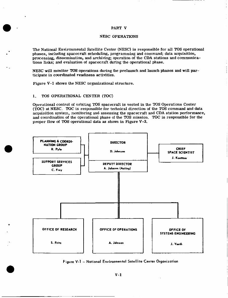
PART V
PLANNING 6 COORDI-
R. Pyle NATION GROUP -.
7
I
SUPPORT SERVICES GROUP L
C. Frey
NESC OPERATIONS
DIRECTOR
D. Johnson
I CHIEF
SPACE SCIENTIST
J. Kuellnn
DEPUTY DIRECTOR A. Johnson (Acting)
I1
The National Environmental Satellite Center (NESC) is responsible for all TOS operational phases, including spacecraft scheduling, programming and command; data acquisition, processing, dissemination, and archiving; operation of the CDA stations and communica- tions links; and evaluation of spacecraft during the operational phase.
NESC will monitor TOS operations during the prelaunch and launch phases and will par- ticipate in coordinated readiness activities.
Figure V-1 shows the NESC organizational structure.
i
OFFICE OF RESEARCH OFFICE OF OPERATIONS
5. Fritz A. Johnson
1. TOS OPERATIONAL CENTER (TOC)
OFFICE OF SYSTEMS ENGINEERING
J. Vaeth
Operational control of orbiting TOS spacecraft is vested in the TOS Operations Center (TOC) at NESC. TOC is responsible for technical direction of the TOS command and data acquisition system, monitoring and assessing the spacecraft and CDA station performance, and coordination of the operational phase of the TOS mission. TOC is responsible for the proper flow of TOS operational data as shown in Figure V-2.
v-1
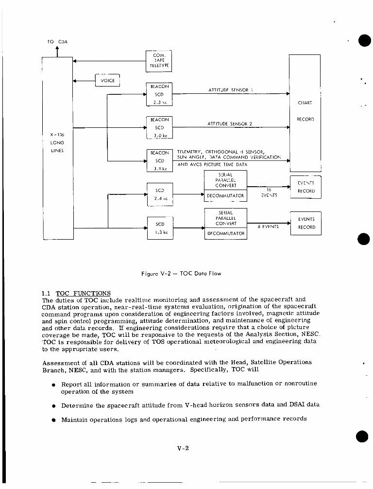
TO CDA
t
X-136
L O N G
LINES
BEACON ATTITUDE SENSOR 2
SCD b
TELETYPE
BEACON
RECORD
I 1 2.3 kc I
BEACON
b SCD
3 . 9 kc
CHART
TELEMETRY, ORTHOGONAL H SENSOR, SUN ANGLE, DATA COMMAND VERIFICATION
A N D AVCS PICTURE TIME DATA
SCD
2 . 4 kc
I 3.0 kc I
EVENTS
16 RECORD
PARALLEL CONVERT
DECOMMUTATOR EVENTS
SCD PARALLEL EVENTS CONVERT - 8 EVENTS RECORD
I 1 . 3 k c I I DECOhlMUTATOR I w I I
Figure V-2 - TOC Data Flow
1.1 TOC FUNCTIONS The duties of TOC include realtime monitoring and assessment of the spacecraft and CDA station operation, near-real-time systems evaluation, origination of the spacecraft command programs upon consideration of engineering factors involved, magnetic attitude and spin control programming, attitude determination, and maintenance of engineering and other data records. If engineering considerations require that a choice of picture coverage be made, TOC wil l be responsive to the requests of the Analysis Section, NESC TOC is responsible for delivery of TOS operational meteorological and engineering data to the appropriate users.
Assessment of all CDA stations will be coordinated with the Head, Satellite Operations Branch, NESC, and with the station managers. Specifically, TOC will
0 Report all information or summaries of data relative to malfunction or nonroutine operation of the system
0 Determine the spacecraft attitude from V-head horizon sensors data and DSAI data
Maintain operations logs and operational engineering and performance records
v-2
I - -
I - -
0 Catalog all reports and data coming into and leaving TOC into a permanent TOS file
0 Maintain appropriate graphic displays
1.2 ATTITUDE DETERMINATION TOC will make manual measurements of the analog V-head horizon sensor Brush recorder data fo r determination of instantaneous roll e r r o r s and wi l l produce the attitude for each orbit. TOC with the assistance of DAPAF wi l l produce the definitive attitude(s) for each day. Definitive attitude plus an attitude prediction will be made available to the Analysis Section and DAPAF for input to the gridding programs.
1.3 BEACON DATA Beacon data received from the CDA station will be recorded on analog Brush recorder
0 Prepare, coordinate, and disseminate a long-term schedule of station readouts based on operation of the spacecrafts in orbit.
0 Prepare and transmit daily to CDA stations a schedule of CDA station readouts
0 Originate and transmit to the CDA stations the specific command programs and station interrogation schedules for daily operations based on the following:
Analysis of predictions as to locations of suitable photographic areas and times of passes over CDA stations
Analysis of programming recpest::
Analysis of spacecraft power
Analysis of CDA station status
0 Program the magnetic attitude and spin control subsystems based on all available attitude and spin information
0 Transmit changes to the program and operating instructions to the CDA stations, the Analysis Section, and DAPAF
0 Insure the timely transmission of all operational data to and from the CDA stations
charts and manual measurements will be made. The data will also be recorded on a multichannel magnetic tape recorder. Simultaneously an analog-to-digital converter will digitize the data. The digital data will be processed in DAPAF and appropriate graphic displays will be delivered to TOC and the Analysis Section. The normal mode of space- craft housekeeping telemetry process will be a quick look at analog records at TOC and a computer printout of all engineering units. Telemetry values beyond tolerance will be known and will be checked as the orbits occur. On a daily basis, the digitized telemetry data will be processed through DAPAF and a page print of the actual data measurements will be obtained. Periodically DAPAF w i l l provide a historical record plot of the telemetry parameters. These plots will become part of the TOC files and will be used for space- craft assessment as required. Copies of these data will be made available by TOC to RCA-AED and TEC as required for use in the postlaunch evaluation.
2. DATA PROCESSING AND ANALYSIS FACILITY (DAPAF)
The DAPAF, at Suitland, Md., is part of the central NESC operating unit and will proccss, analyze, and distribute the meteorological data. DAPAF will use general and special
v-3
purpose computer equipment to locate, format, and digitize the input data and to produce scale-rectified-digital map printouts and other summaries of the meteorological observa- tions. Gridded TV photographs of the cloudcover will be reproduced on kinescope equip- ment. DAPAF w i l l also process beacon data in support of TOC and the evaluation effort.
DAPAF will produce the meteorological data in a manner to permit optimum storage of large quantities of data and rapid manual and automatic information retrieval.
DSD will send minute vector tapes containing the basic orbital elements and the celestial coordinates of the satellite as function of time to TOC for use in DAPAF.
DAPAF wi l l provide the following support for operational spacecraft:
0 Compute equator crossings
0 Compute antenna pointing angles for the CDA stations on punched paper tape for direct teletype transmission
0 Prepare Attitude World Map, Wheel (ATMAPW) and/or World Map and Station Acquisition Data (WMSAD) information
0 Provide TOC with predictions of the following quantities:
Spacecraft location versus time
Times at which the spacecraft is above the horizon and antenna limits at the CDA stations and local coordinates of the spacecraft from each CDA station during contact intervals
Solar angle at the satellite subpoint and the picture center
Spacecraft roll angle versus time
Picture center as a function of time
Location of sunglint in the pictures '
0 Provide TOC with predictions of those times at which a given TOS spacecraft will be close enough to another TOS spacecraft in orbit to produce a conflict in command and acquisition of data
0 Provide realtime processing of selected portions of spacecraft telemetry
e Determine spacecraft attitude and spin rate from the digital spacecraft infrared V-head horizon sensor data
0 Provide TOC both long and short range predictions of spacecraft spin-axis attitude, incorporating magnetic, gravitational, and eddy-current torque effects
0 Provide the NESC Analysis Branch with electronically gridded pictures, grids for pictures, digitized pictures, digitized gridded pictures, and gridded rectified mosaics as required
v-4
0 Provide TOC with the information necessary for manual gridding of APT pictures in the proper APT message code. This data will be presented on punched paper tape for transmission over worldwide teletype networks.
0 Provide analytical and technical consultants and computer support to the TOS project for many phases of the TOS mission.
3. ARCHIVAL PLANS
Archiving of TOS data is the responsibility of NESC. The NESC Photographic Laboratory will process all film for archival purposes. The final repository of TQS archival film is the Nationai “w’eather Records Center (SiiWRC) of ESSAis Envlronmentai Data Service at Asheville, N. C. Duplicate films of TOS picture sequences will be available to the public on request to NWRC. The film will be supplied in the form of 35-mm positive trans- parencies o r negatives on 100-ft reels. All pictures and picture sequences will be accompanied by the documentation necessary for data retrieval.
The Photographic Laboratory, NESC, will be responsible for archiving video data and will perform the following functions:
0 Record in a master film file all original film negatives.
0 Check and record density values of all original films.
0 Request reruns as necessary directly from DAPAF.
0 Assemble all checked films into final orbital sequence.
0 Mail f ina l archival products to NWRC.
The Photo Lab will reproduce original f i lms and prepare archival films. The film products will be distributed by NESC in accordance with an archival distribution formula. DAPAF will provide TEC with a copy of a representative negative daily and 50 copies of an 8 x 10 selected annotated glossy print weekly.
v-5
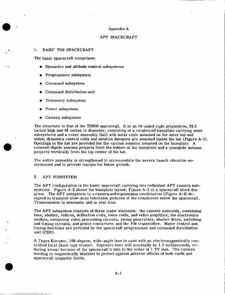
0 -
.
c
Appendix A
APT SPACECRAFT
1. BASIC TOS SPACECRAFT
The basic spacecraft comprises:
Dynamics and attitude control subsystems
Programmer subsystem
e Command subsystem
Command distribution unit
Telemetry subsystem
Power subsystem
Camera subsystem
The structure is that of the TIROS spacecraft. It is an 18-sided right polyhedron, 22.5 inches high and 42 inches in diameter, consisting of a reinforced baseplate carrying most subsystems and a cover assembly (hat) with solar cells mounted on the outer top and sides; dynamics control coils and nutation dampers are mounted inside the hat (Figure A-1). Operings in the hat are provided for the various sensors mounted on the baseplate. A crossed-dipole antenna projects f r o m the bottom of the baseplate and a monopole antenna projects vertically from the top center of the hat.
The entire assembly is strengthened to accommodate the severe launch vibration en- vironment and to provide margin for future growth.
2. APT SUBSYSTEM
The APT configuration is the basic spacecraft carrying two redundant APT camera sub- systems. Figure A-2 shows the baseplate layout; Figure A-3 is a spacecraft block dia- gram. The APT subsystem is a camera and transmitter combination (Figure A-4) de- signed to transmit slow-scan television pictures of the cloudcover below the spacecraft. Transmission is automatic and in real time.
The APT subsystem consists of three major elements: the camera assembly, containing lens, shutter, vidicon, deflection coils, focus coils, and video amplifier; the electronics module, containing video processing circuits, sweep generators, shutter drive, switching and timing circuits, and power converters; and the FM transmitter. Major control and timing functions are provided by the spacecraft programmer and command distribution unit (CDU).
A Tegea Kinoptic, 108-degree, wide-angle lens is used with an electromagnetically con- trolled focal plane type shutter. Exposure time will nominally be 1.5 milliseconds, re- ducing smear because of the spacecraft's spin to the order of 1 TV line. The camera housing is magnetically shielded to protect against adverse effects of both earth and spacecraft magnetic fields.
A-1
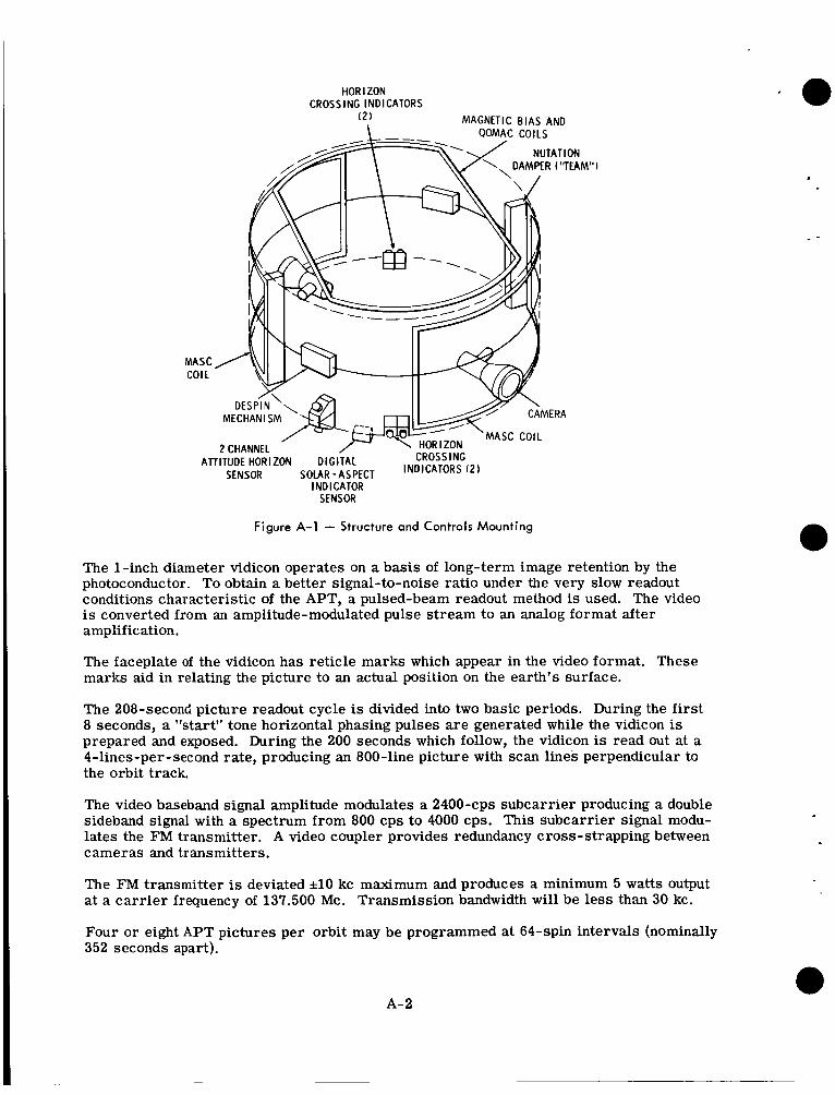
HOR IZON CROSSING INDICATORS
( 2 ) MAGNETIC BIAS AND
MASC COIL
MECHAN I SM
2 CHANNEL
SENSOR
MASC COIL
CROSSING All ITUDE HORIZON DIGITAL SOLAR-ASPECT INDICATORS ( 2 ) INDICATOR
SENSOR
Figure A-1 - Structure and Controls Mounting
The 1-inch diameter vidicon operates on a basis of long-term image retention by the photoconductor. To obtain a better signal-to-noise ratio under the very slow readout conditions characteristic of the APT, a pulsed-beam readout method is used. The video is converted from an amplitude-modulated pulse stream to an analog format after amplification.
The faceplate of the vidicon has reticle marks which appear in the video format. These marks aid in relating the picture to an actual position on the earth's surface.
The 208-second picture readout cycle is divided into two basic periods. During the first 8 seconds, a "start" tone horizontal phasing pulses are generated while the vidicon is prepared and exposed. During the 200 seconds which follow, the vidicon is read out at a 4-lines-per-second rate, producing an 800-line picture with scan lines perpendicular to the orbit track.
The video baseband signal amplitude modulates a 2400-cps subcarrier producing a double sideband signal with a spectrum from 800 cps to 4000 cps. This subcarrier signal modu- lates the FM transmitter. A video coupler provides redundancy cross-strapping between cameras and transmitters.
.
The FM transmitter is deviated it10 kc maximum and produces a minimum 5 watts output at a car r ie r frequency of 137.500 Mc. Transmission bandwidth will be less than 30 kc.
Four or eight APT pictures per orbit may be programmed at 64-spin intervals (nominally 352 seconds apart).
A- 2
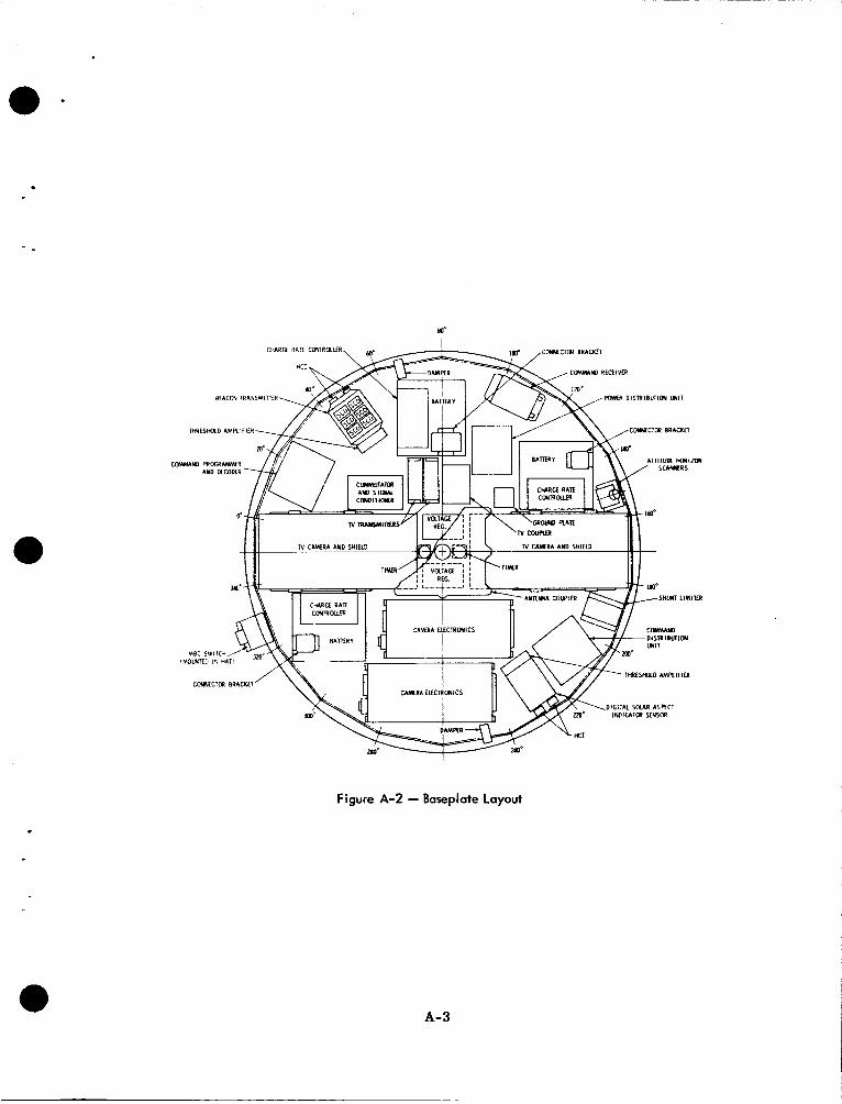
a -
a
. Figure A-2 - Baseplate Layout
a A- 3
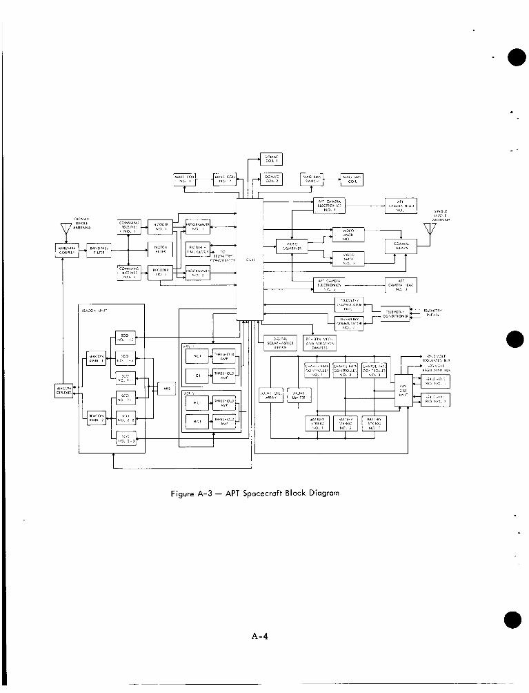
T I I 1 I 1 I
Figure A-3 - APT Spacecraft Block Diagram
A- 4
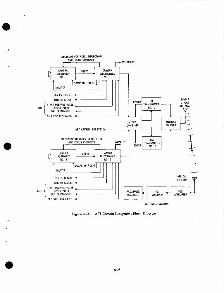
POWER FM - TRANSMIlTER No. 1
ELECTRODE VOLTAGES. DEFLECTION AND FOCUS CURRENTS
SINGLE DIPOLE
ANTENNA
SAMPLING PULSE ?z2l7l7 J
48Wcps CLOCK 1
1 1
VIDEO ANTENNA -
START PREPARE PULSE, 1 EXPOSE PULSE
END OF READOLIT 4 CDU {
d
-..,
I
r -24.5 VDC REGULATED 0
COMBINER / COUPLER
APT FIELD STATION
APT CAMERA SUBSYSTEM
Figure A-4 - APT Camera Subsystem, Block Diagram
- 1
ELECTRODE VOLTAGES, DEFLECTION AND FOCUS CURRENTS TUEMETRY
CAMERA CAMERA VIDEO ASSEMBLY ELECTRONICS -
A- 5
F FM - TRANSMITER POW€R NO. 2
/
NO. 2 NO. 2
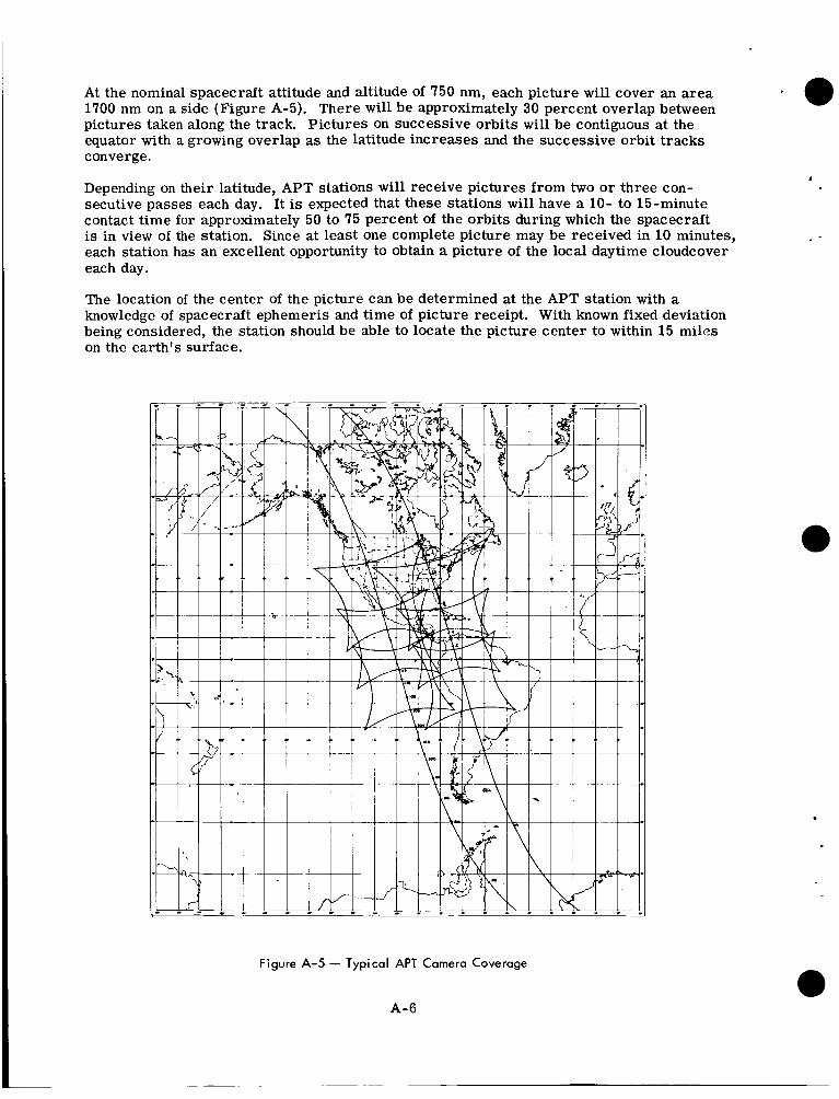
At the nominal spacecraft attitude and altitude of 750 nm, each picture will cover an area 1700 nm on a side (Figure A-5). There will be approximately 30 percent overlap between pictures taken along the track. Pictures on successive orbits will be contiguGus at the equator with a growing overlap as the latitude increases and the successive orbit tracks converge.
Depending on their latitude, APT stations will receive pictures from two o r three con- secutive passes each day. It is expected that these stations will have a 10- to 15-minute contact time for approximately 50 to 75 percent of the orbits during which the spacecraft is in view of the station. Since at least one complete picture may be received in 10 minutes, each station has an excellent opportunity to obtain a picture of the local daytime cloudcover each day.
The location of the center of the picture can be determined at the APT station with a knowledge of spacecraft ephemeris and time of picture receipt. With known fixed deviation being considered, the station should be able to locate the picture center to within 15 miles on the earth’s surface.
.
Figure A-5 - Typical APT Camera Coverage
A-6
3. ATTITUDE AND DYNAMICS
The TOS spacecraft incorporates techniques to provide precise attitude control, camera pointing, spin-rate control, and timing functions.
3.1 ATTITUDE CONTROL The pictures must be taken when the camera optical axis is collinear to within 1 degree d the local vertical, i.e., looking straight down, anywhere in the sunlit portion of the orbit.
The spacecraft spin axis, in orbit, wil l be maintained normal to the orbital plane to within 1 degree. The view axes of the two cameras are mounted normal to the spin axis; there- ~ E P , IC Lhe spacecrzft rotztes &u?iit itis axis, each camera alternately looks toward and away from the earth. The wheel attitude wi l l be established and accurately maintained with the quarter-orbit magnetic attitude control (QOMAC), magnetic bias control (MBC), and nutation dampers.
QOMAC uses a current-carrying coil to generate a controlled magnetic field which in- teracts with the earth's magnetic field to torque the spinning spacecraft. The programmer, after instructions from the ground station, reverses the direction of the current in the coil each quarter orbit. The phasing of these switching points will be controlled so that for over half an orbit the nominal average torque axis position and direction of torque are controllable.
.
MJ3C will be used to eliminate any unwanted spin axis drift in orbit; MBC will null the spacecraft's residual dipole moment and compensate for the effects of the regressing orbit, thereby reducing the number of QOMAC cycles required for station keeping. The magnitude and polarity of the dipole compensations afforded by MBC is controlled from the ground by command.
An effective nutation damping system will be provided to rapidly reduce any imparted nutation to a negligible value. Two tuned energy-absorbing mass (TEAM) dampers will rapidly reduce any nutation cone half angle to a value below 0.7 degree. A liquid damper will maintain the nutation angle at a level of the order of 0.2 degree. A low nutation angle is desired for accuracy of camera aiming and for facilitating the processing of data from the V-head horizon sensor.
3.2 ATTITUDE DETERMINATION AND CAMERA TRIGGER
3.2.1 V-HEAD HORIZON SENSORS For satisfactory picture taking, the spin axis must be maintained normal to the orbit plane and the camera shutter must be triggered at the desired instant in the rotation. Spin axis attitude is determined from telemetry of outputs from both channels of the at- titude horizon sensor (AHS) and from a telemetered digital solar aspect (DSAI) sensor output. Telemetered data from the horizon crossing indicator (HCI) may also be used to derive attitude data. The solar aspect sensor is most useful in initial maneuvers when both channels of the V-head sensor do not intersect the earth, or in the event of failure of one of the V-head elements. When the V-head scanner data is used and nutation is allowed for, the uncertainty in roll and yaw at time of shutter should be less than 0.5 degree.
The AHS contains two infrared bolometers with optical axes in a V-configuration (Fig- ure A-6). The optical paths of the sensors may intersect with the earth as the spacecraft spins; measurement of the earth- sky time ratios between the pulses is used to determine spin axis attitude. The digital solar aspect indicator produces a code indicative of the solar aspect angle once each rotation of the spacecraft. Resolution is 1 degree over a 128-degree range.
A-7
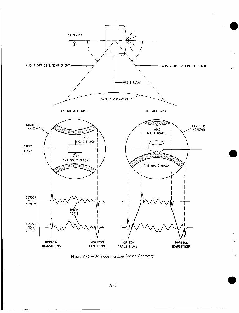
S P I N A X I S
r
7 A H S - 1 OPTICS LINE OF SIGHT A H S - 2 OPTICS LINE OF SIGHT
-ORBIT PLANE
EARTH'S CURVATURE
( A ) NO ROLL ERROR ( B ) ROLL ERROR
AHS NO. 2 TRACK
EARTH I R H O R I Z O N
I I I I I I I I I I
SENSOR NO 1
OUTPUT
SENSOR NO 2
OUTPUT
HORIZON TRANSITIONS
HOR I ZON HORIZON TRANSITIONS TRANS IT IONS
HOR I ZON TRANSITIONS
Figure A-6 - Attitude Horizon Sensor Geometry
A- a
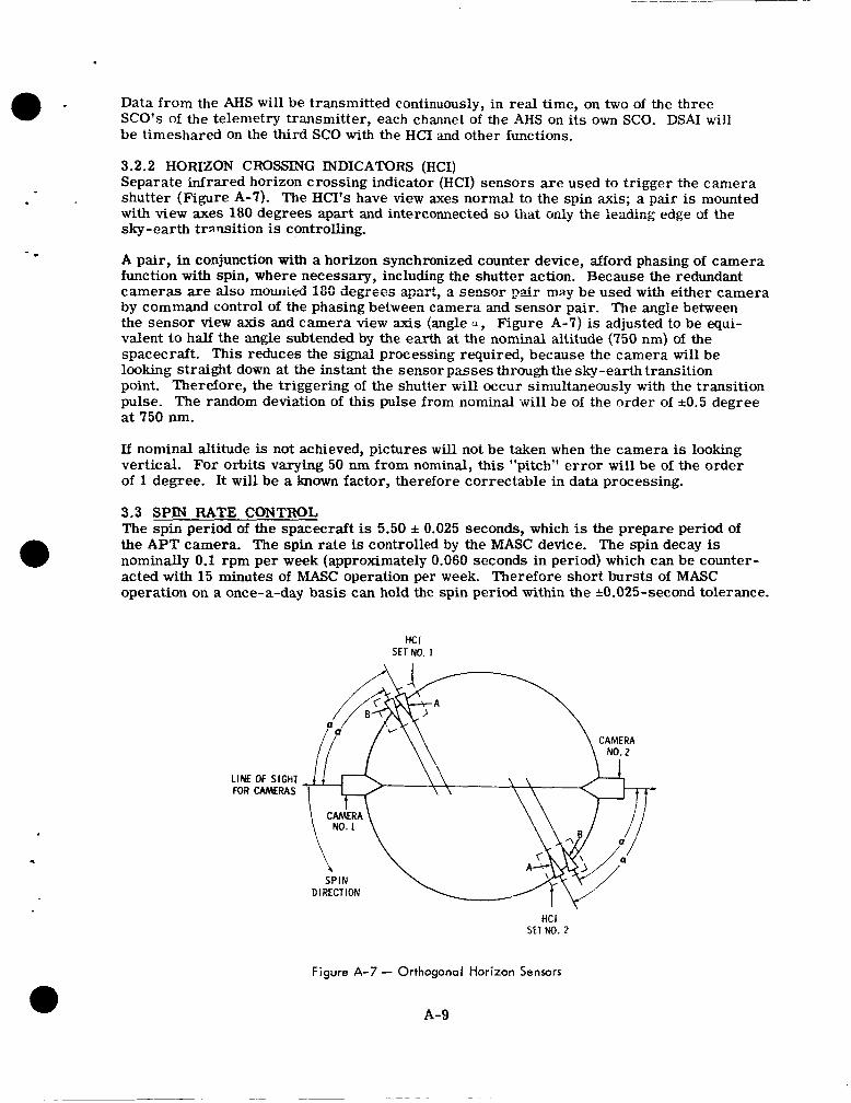
Data from the AHS wil l be transmitted continuously, in real time, on two of the three SCO's of the telemetry transmitter, each channel of the AHS on its own SCO. DSAI will be timeshared on the third SCO with the HCI and other functions.
e -
-
3.2.2 HORIZON CROSSING INDICATORS (HCI) Separate infrared horizon crossing indicator (HCI) sensors are used to trigger the camera shutter (Figure A-7). The HCI's have view axes normal to the spin axis; a pair is mounted with view axes 180 degrees apart and interconnected so that only the :exling edge Qf t!!e sky-earth transition is controlling.
A pair, in conjunction with a horizon synchronized counter device, afford phasing of camera function with spin, where necessary, including the shutter action. Because the redundant cameras are ais0 mmmteci 18C degxes apart, 2 sensor p i r may be used with either camera by command control of the phasing between camera and sensor pair. The angle between the sensor view axis and camera view axis (angle a , Figure A-7) is adjusted to be equi- valent to half the angle subtended by the earth at the nominal altitude (750 nm) of the spacecraft. This reduces the signal processing required, because the camera will be looking straight down at the instant the sensor passes through the sky-earth transition point. Therefore, the triggering of the shutter will occur simultaneously with the transition pulse. The random deviation of this pulse from nominal w i l l be of the order of k0.5 degree at 750 nm.
If nominal altitude is not achieved, pictures will not be taken when the camera is looking vertical. For orbits varying 50 nm from nominal, this "pitch" error will be of the order of 1 degree. It will be a known factor, therefore correctable in data processing.
3.3 SPIN RATE CONTROL The spin period of the spacecraft is 5.50 f 0.025 seconds, which is the prepare period of the APT camera. The spin rate is controlled by the MASC device. The spin decay is nominally 0.1 rpm per week (approximately 0.060 seconds in period) which can be counter- acted with 15 minutes of MASC operation per week. Therefore short bursts of MASC operation on a once-a-day basis can hold the spin period within the k0.025-second tolerance.
a HC I
SET NO. 1
LINE OF SlGtiT FOR CAMERAS
HCI SET NO. 2
Figure A-7 - Orthogonal Horizon Sensors
A-9
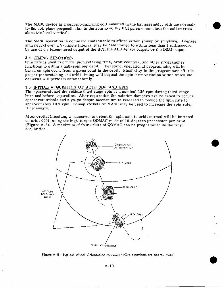
The MASC device is a current-carrying coil mounted in the hat assembly, with the nornial- to-the coil plane perpendicular to the spin axis; the HCI pairs commutate the coil current about the local vertical.
The MASC operation is command controllable to afford either spinup or spindown. Average spin period over a 5-minute interval may be determined to within less than 1 millisecond by use of the telemetered output of the HCI, the AHS sensor output, o r the DSAI output.
3.4 TIMING FUNCTIONS Spin rate is used to control picturetaking time, orbit counting, and other programmer functions to within a half-spin per orbit. Therefore, operational programming will be based on spin count from a given point in the orbit. Flexibility in the programmer affords proper picturetaking and orbit timing well beyond the spin-rate variation within which the cameras will perform satisfactorily.
3.5 INITIAL ACQUISITION O F ATTITUDE AND SPIN The spacecraft and the vehicle third stage spin at a nominal 126 rpm during third-stage burn and before separation. After separation the nutation dampers a r e released to reduce spacecraft wobble and a yo-yo despin mechanism is released to reduce the spin rate to approximately 10.9 rpm. Spinup rockets or MASC may be used to increase the spin rate, if necessary.
After orbital injection, a maneuver to orient the spin axis to orbit normal will be initiated on orbit 0001, using the high-torque QOMAC mode of 10-degrees precession per orbit (Figure A-8). A maximum of four orbits of QOMAC can be programmed on the f i rs t acquisition.
O R I E N T A T I O N AT SEPARATION
- 6 TH ORBIT
-1OTH ORBIT
O R I E N T A T I O N AT SEPARATION
- 6 TH ORBIT
/- I-{: I -\- x ATTITUDE T O R Q U I N G
PHASE
-1OTH ORBIT
i,
WHEEL O R I E N T A T I O N
Figure A-8- Typical Wheel Orientation Maneuver (Orbit numbers are approximate)
A-10
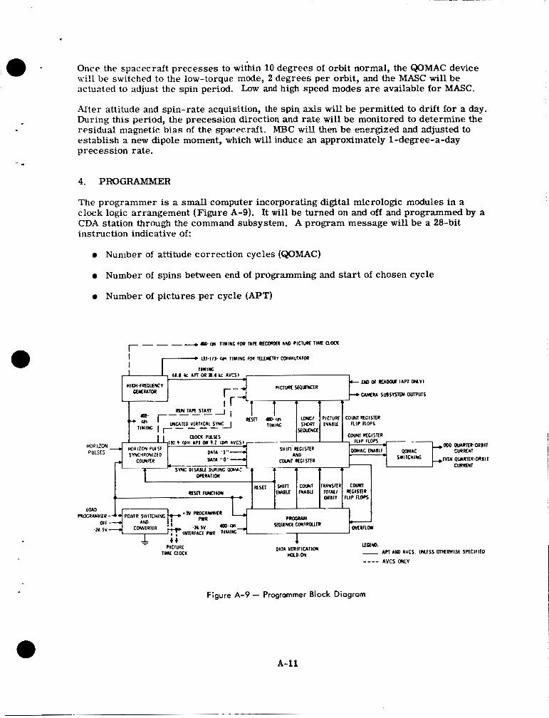
Once the spacecraft precesses to wit'hin 10 degrees of orbit normal, the QOMAC device will be switched to the low-torque mode, 2 degrees per orbit, and the MASC will be actuated to adjust the spin period. Low and high speed modes are available for MASC.
After attitude and spin-rate acquisition, the spin axis will be permitted to drift for a day, During this period, the precession direction and rate will be monitored to determine the residual magnetic bias of t h e spacecraft. MBC will then be energized and adjusted to establish a new dipole moment, which will induce an approximately 1-degree-a-day precession rate.
4. PROGRAMMER
The programmer is a small computer incorporating digital micrologic modules in a clock logic arrangement (Figure A-9). It will be turned on and off and programmed by a CDA station through the command subsystem. A program message will be a 28-bit instruction indicative of:
0 Number of attitude correction cycles (QOMAC)
0 Number of spins between end of programming and start of chosen cycle
0 Number of pictures per cycle (APT)
Figure A-9 - Programmer Block Diagram
A-11
0 Number of spins in an orbit
0 Selection of @MAC or picturetaking control
The spacecraft ca r r i e s two redundant programmers, either of which may control @MAC or picturetaking. Both functions may be accomplished simultaneously with both program- mers operating,
The programmer has the capability of:
0
0
0
0
0
0
0
Initiating picturetaking and attitude-correction cycles at a point remote from the CDA station. The delay is derived from spin count and will be a maximum of about 188 minutes.
Controlling the number of pictures to be taken on each orbit and the interval between pictures. Either a 4- or 8-picture sequence may be programmed at an interval of 352 seconds (64 spins) between pictures.
Turning camera power off at the end of a sequence, and restarting the cycle in the next orbit. Therefore, the orbit period becomes a basic timing cycle. Orbit periods which may be accommodated with nominal spin-rates will be from approximately 94 minutes to 188 minutes (1024 to 2048 spins). The programmer will repeat the sequence each orbit until turned off or reprogrammed by ground command.
Providing synchronization of spacecraft operations with the spacecraft spin-rate, automatically rephasing i f synchronization is disturbed, and providing backup horizon crossing pulses if the HCI output pulses a r e interrupted, thereby permitting the satellite spin-rate to be a timing source. A horizon sync counter is synchronized to the sky-earth transition pulse output of the orthogonal horizon sensor. It discrimi- nates against earth noise pulses which may follow this leading edge pulse by means of a gating operation using outputs from the HCI. The output is one pulse per spin of the spacecraft, generated in phase with the output of the HCI associated with the camera being used. Perfect synchronization will be afforded with spin periods varying from 5.12 seconds up to 100 milliseconds longer than the nominal 5.5- seconds spin period.
Providing quarter-orbit timing and control of number of cycles for @MAC opera- tion. In the QOMAC mode the programmer is not synchronized to horizon pulses, because the horizon sync counter is programmed to operate in a free running mode at the nominal spin rate. This is necessary because in the initial orientation ma- neuvers immediately after launch the orthogonal horizon sensors do not see the earth. Quarter-orbit periods which may be accommodated a r e from 24 to 47 minutes.
Providing synchronized control of the camera subsystems. The outputs of the pro- grammer supply power control of camera and transmitter, initiation of prepare cycle, shutter trigger, and gated timing.
Providing the precise frequencies required. The programmer will incorporate a crystal-controlled oscillator nominally accurate to 5 parts in lo-’. Outputs from divider chains a re available for desired frequencies.
5. COMMAND SUBSYSTEM
The command subsystem comprises two redundant fixed-tuned AM r e c e i v e d t o n e de- tectors and decoder units (Figure A-10). The receiver and tone detectors operate
A-12
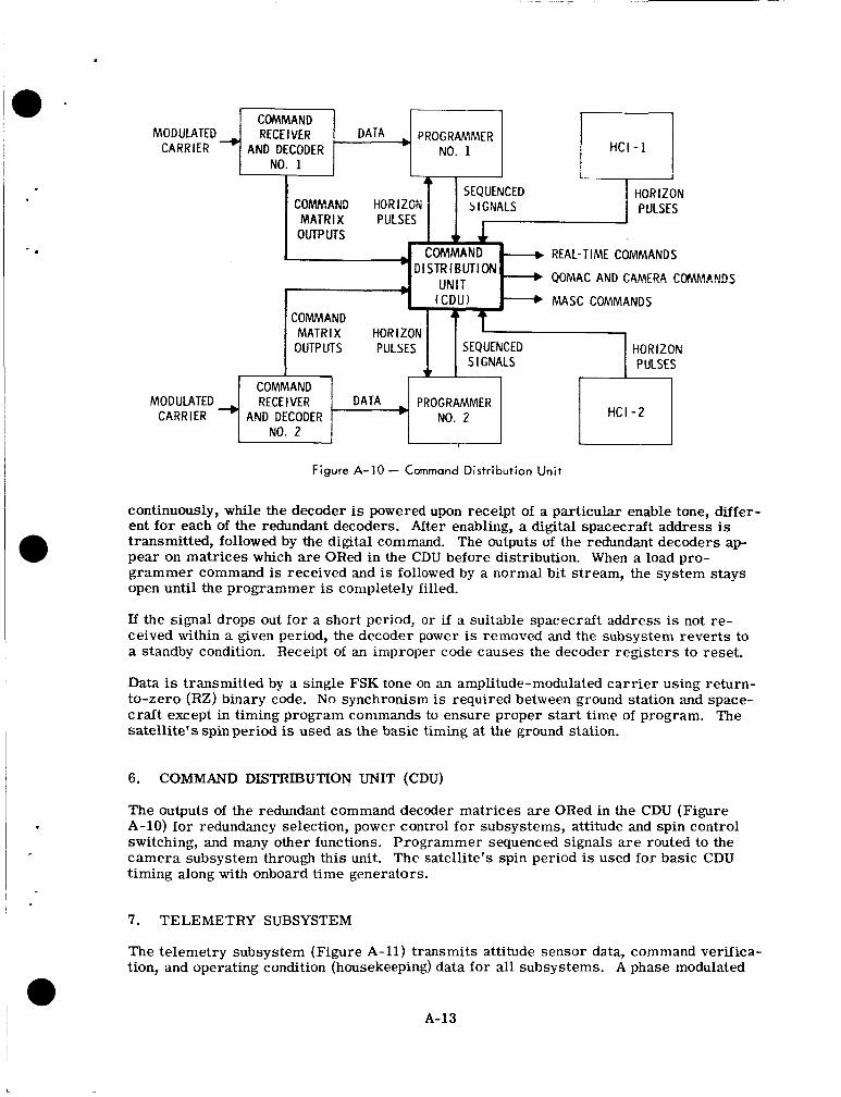
M O D U L A T E D ~ RECEIVER 1 DATA 4 PROGRAMMER CARRIER AND DECODER NO. 1
OUTPUTS PULSES SEQUENCED
+ S I GNALS
I NO. 1 I I
HORIZON PULSES
SEQUENCED COMMAND HORiZGN
COMMAND MODULATED RECEIVER
CARRIER AND DECODER NO. 2
HC1-l I
DATA PROGRAMMER H C I - 2 NO. 2
I
Figure A-10 - Command Distribution Unit
continuously, while the decoder is powered upon receipt of a particular enable tone, differ- ent for each of the redundant decoders. After enabling, a digital spacecraft address is transmitted, followed by the digital command. The outputs of the redundant decoders ap- pear on matrices which are ORed in the CDU before distribution. When a load pro- grammer command is received and is followed by a normal bit stream, the system stays open until the programmer is completely filled.
If the signal drops out for a short period, o r if a suitable spacecraft address is not re- ceived within a given period, the decoder power is removed and the subsystem reverts to a standby condition. Receipt of an improper code causes the decoder registers to reset.
Data is transmitted by a single FSK tone on an amplitude-modulated ca r r i e r using return- to-zero (RZ) binary code. N o synchronism is required between ground station and space- craft except in timing program commands to ensure proper start time of program. The satellite's spin period is used as the basic timing at the ground station.
6. COMMAND DISTRIBUTION UNIT (CDU)
The outputs of the redundant command decoder matrices are ORed in the CDU (Figure A-10) for redundancy selection, power control for subsystems, attitude and spin control switching, and many other functions. Programmer sequenced signals are routed to the camera subsystem through this unit. The satellite's spin period is used for basic CDU timing along with onboard time generators.
7. TELEMETRY SUBSYSTEM
The telemetry subsystem (Figure A-11) transmits attitude sensor data, command verifica- tion, and operating condition (housekeeping) data for all subsystems. A phase modulated
A-13
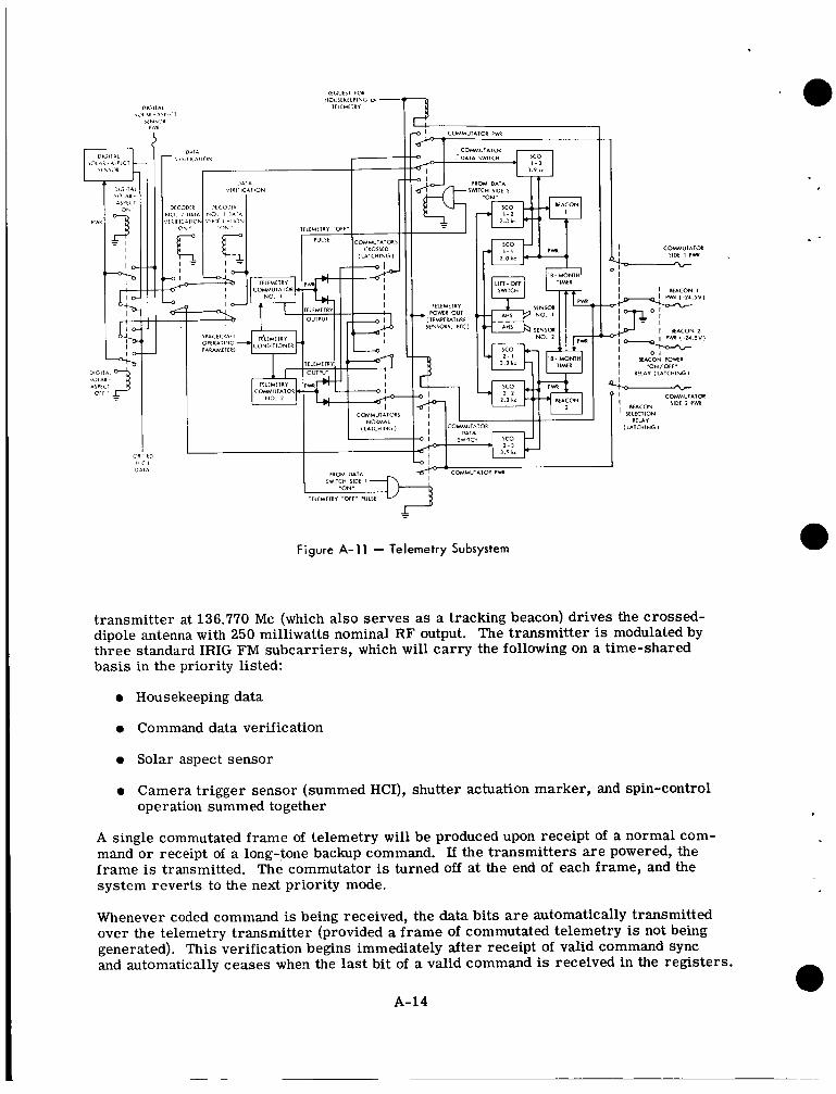
I C O M M U l I l O L I SIDE I PM
I I K O N I
I L A C O N 2
I "oN/orr" I RELAY ( L A I C H I N G I -
C O k v * U l A l w I ' BEACON 'IEf ' SELECTION RELAY
I LATCHING 1
I P I O M DATA
IWIlCH SIDE I
1ELLMtTRY "WF" PULSE
Figure A-1 1 - Telemetry Subsystem
transmitter at 136.770 Mc (which also serves as a tracking beacon) drives the crossed- dipole antenna with 250 milliwatts nominal R F output. The transmitter is modulated by three standard IRIG FM subcarriers, which will carry the following on a time-shared basis in the priority listed:
0 Housekeeping data
0 Command data verification
0 Solar aspect sensor
0 Camera trigger sensor (summed HCI), shutter actuation marker, and spin-control operation summed together
A single commutated frame of telemetry will be produced upon receipt of a normal com- mand o r receipt of a long-tone backup command. If the transmitters a re powered, the frame is transmitted. The commutator is turned off at the end of each frame, and the system reverts to the next priority mode.
Whenever coded command is being received, the data bits a r e automatically transmitted over the telemetry transmitter (provided a f rame of commutated telemetry is not being generated). This verification begins immediately after receipt of valid command sync and automatically ceases when the last bit of a valid command is received in the registers.
A-14
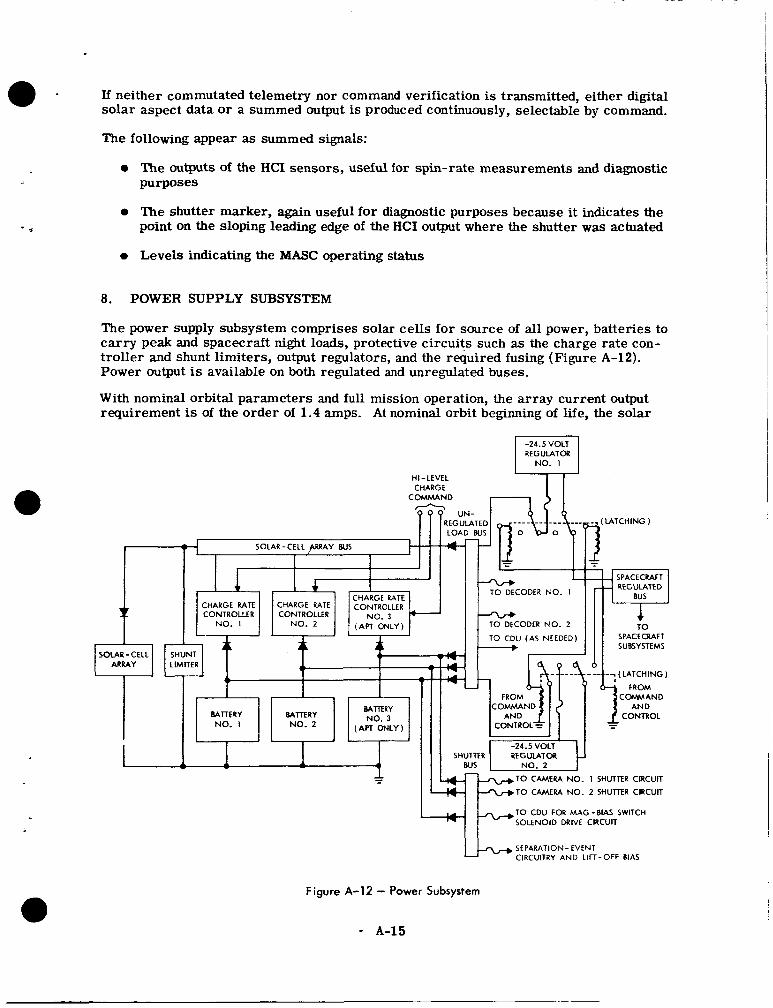
If neither commutated telemetry nor command verification is transmitted, either digital solar aspect data or a summed output is produced continuously, selectable by command.
The following appear as summed signals:
0 The outputs of the HCI sensors, useful for spin-rate measurements and diagnostic purposes
0 The shutter marker, again useful for diagnostic purposes because it indicates the point on the sloping leading edge of the HCI output where the shutter was actuated
0 Levels indicating the MASC operating status
8. POWER SUPPLY SUBSYSTEM
The power supply subsystem comprises solar cells for source of all power, batteries to carry peak and spacecraft night loads, protective circuits such a s the charge rate con- troller and shunt limiters, output regulators, and the required fusing (Figure A-12). Power output is available on both regulated and unregulated buses.
With nominal orbital parameters and full mission operation, the a r r ay current output requirement is of the order of 1.4 amps. At nominal orbit beginning of life, the solar
-24.5 VOLT REGULATOR
NO. 1
HI - LEVEL CHARGE
TO DECODER NO. 1
TO CDU (AS NEEDED)
TO CAMERA NO. 2 SHUTTER CIRCUIT
TO CDU FOR MAG-BIAS SWITCH SOLENOID DRIVE CIRCUIT
SEPARATION- EVENT CIRCUITRY AND LIFT-OFF BIAS
Figure A-12 - Power Subsystem
* A-15
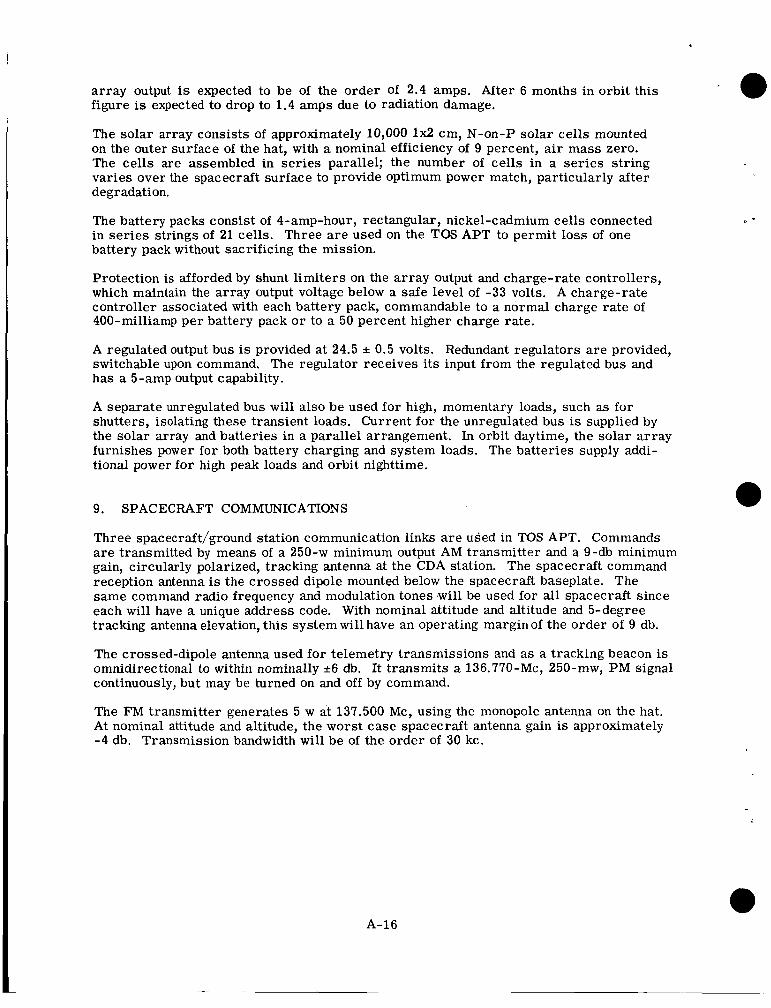
array output is expected to be of the order Of 2.4 amps. After 6 months in orbit this figure is expected to drop to 1.4 amps due to radiation damage.
The solar array consists of approximately 10,000 1x2 cm, N-on-P solar cells mounted on the outer surface of the hat, with a nominal efficiency of 9 percent, air mass zero. The cells are assembled in ser ies parallel; the number of cells in a ser ies string varies over the spacecraft surface to provide optimum power match, particularly after degradation.
The battery packs consist of 4-amp-hour, rectangular, nickel-cadmium cells connected in ser ies strings of 21 cells. Three a r e used on the TOS APT to permit loss of one battery pack without sacrificing the mission.
Protection is afforded by shunt limiters on the array output and charge-rate controllers, which maintain the array output voltage below a safe level of -33 volts. A charge-rate controller associated with each battery pack, commandable to a normal charge rate of 400-milliamp per battery pack o r to a 50 percent higher charge rate.
A regulated output bus is provided at 24.5 f 0.5 volts. Redundant regulators a r e provided, switchable upon command. The regulator receives its input from the regulated bus and has a 5-amp output capability.
A separate unregulated bus will also be used for high, momentary loads, such as for shutters, isolating these transient loads. Current for the unregulated bus is supplied by the solar array and batteries in a parallel arrangement. In orbit daytime, the solar array furnishes power for both battery charging and system loads. The batteries supply addi- tional power for high peak loads and orbit nighttime.
9. SPACECRAFT COMMUNICATIONS
Three spacecraft/ground station communication links a r e used in TOS APT. Commands a r e transmitted by means of a 250-w minimum output AM transmitter and a 9-db minimum gain, circularly polarized, tracking antenna at the CDA station. The spacecraft command reception antenna is the crossed dipole mounted below the spacecraft baseplate. The same command radio frequency and modulation tones ,will be used for all spacecraft since each will have a unique address code. With nominal attitude and altitude and 5-degree tracking antenna elevation, this system will have an operating margin of the order of 9 db.
The crossed-dipole antenna used for telemetry transmissions and as a tracking beacon is omnidirectional to within nominally +6 db. It transmits a 136.770-Mc, 250-mw, P M signal continuously, but may be turned on and off by command.
The FM transmitter generates 5 w at 137.500 Mc, using the monopole antenna on the hat. At nominal attitude and altitude, the worst case spacecraft antenna gain is approximately -4 db. Transmission bandwidth will be of the order of 30 kc.
A-16
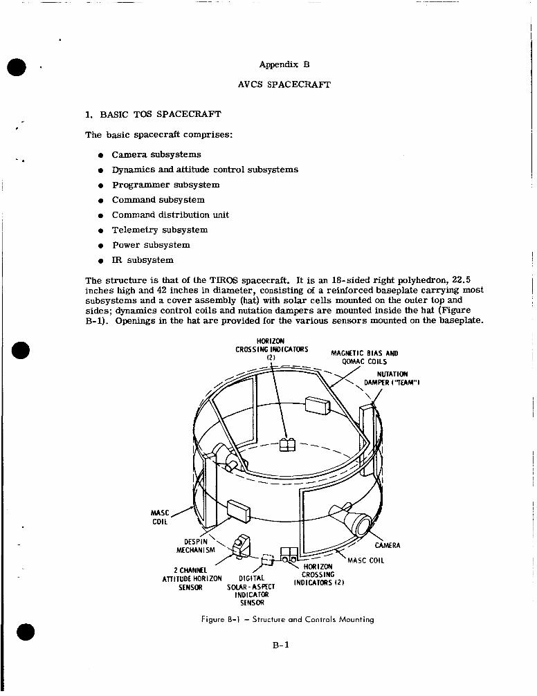
Appendix B
AVCS SPACECRAFT
1. BASIC TOS SPACECRAFT
The basic spacecraft comprises:
0 Camera subsystems
0 Dynamics and attitude control subsystems 0 Programmer subsystem 0 Command subsystem 0 Command distribution unit 0 Telemetry subsystem 0 Power subsystem 0 IR subsystem
The structure is that of the TIROS spacecraft. It is an 18-sided right polyhedron, 22.5 inches high and 42 inches in diameter, consisting of a reinforced baseplate carrying most subsystems and a cover assembly (hat) with solar cells mounted on the outer top and sides; dynamics control coils and nutation dampers are mounted inside the hat (Figure B-1). Openings in the hat are provided for the various sensors mounted on the baseplate.
HORIZON .-. MAGNETIC BIAS AND
MASC COIL
ATTITUDE HORIZON DIG1 SDUR-ASPfCT INDICATORS (21 SENSOR INDICATOR
SENSOR
Figure B-1 - Structure and Controls Mounting
B- 1
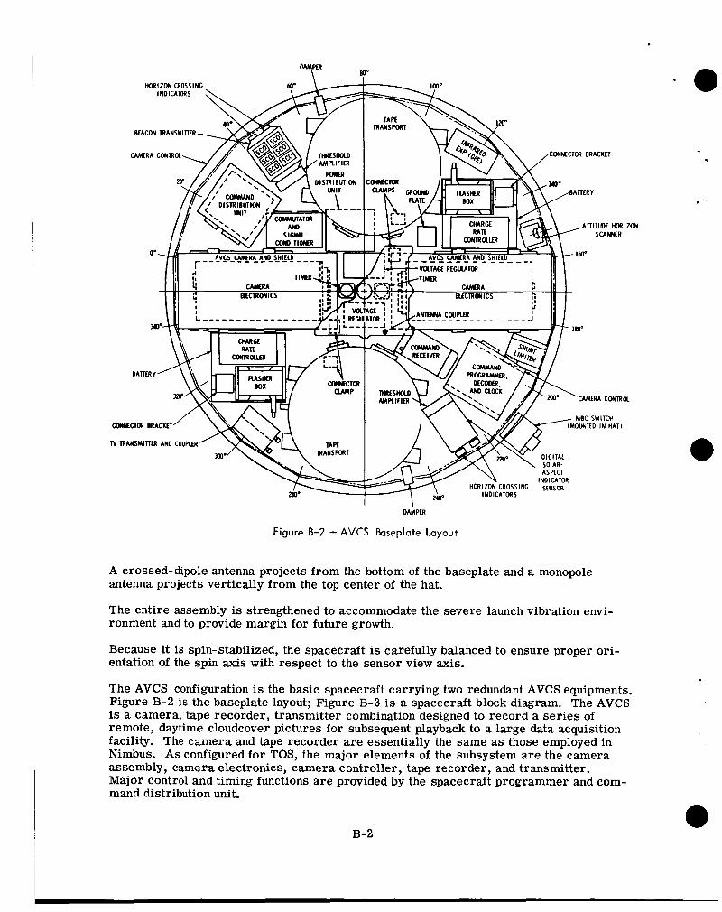
Figure 8-2 - AVCS kseplate Layout
A crossed-dipole antenna projects from the bottom of the baseplate and a monopole antenna projects vertically from the top center of the hat.
The entire assembly is strengthened to accommodate the severe launch vibration envi- ronment and to provide margin for future growth.
Because it is spin-stabilized, the spacecraft is carefully balanced to ensure proper ori- entation of the spin axis with respect to the sensor view axis.
The AVCS configuration is the basic spacecraft carrying two redundant AVCS equipments. Figure B-2 is the baseplate layout; Figure B-3 is a spacecraft block diagram. The AVCS is a camera, tape recorder, transmitter combination designed to record a series of remote, daytime cloudcover pictures for subsequent playback to a large data acquisition facility. The camera and tape recorder a re essentially the same as those employed in Nimbus. A s configured for TOS, the major elements of the subsystem are the camera assembly, camera electronics, camera controller, tape recorder, and transmitter. Major control and timing functions a re provided by the spacecraft programmer and com- mand distribution unit.
B-2
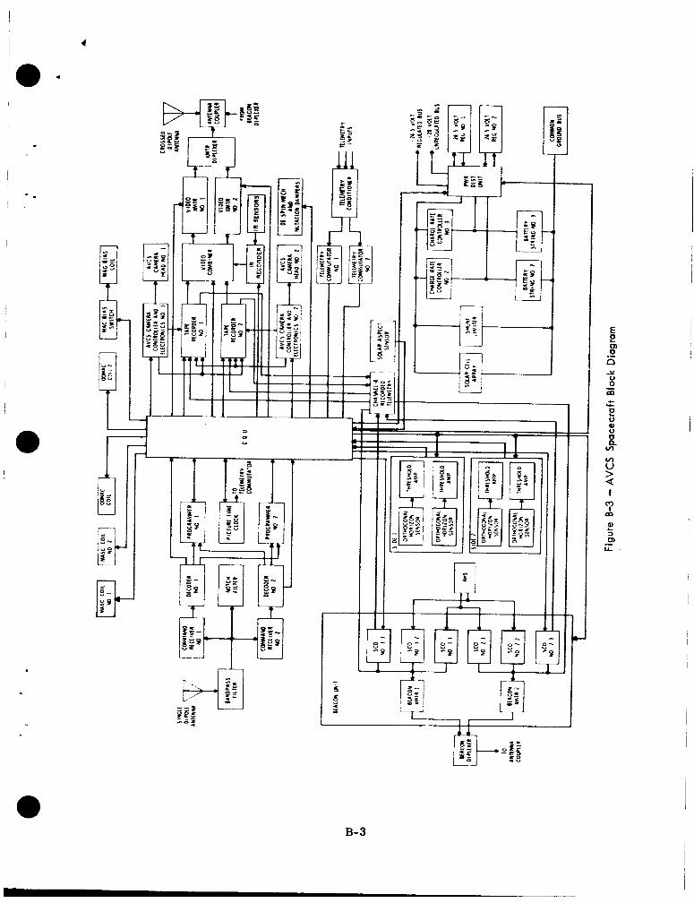
3 0 u 7
E E
n
:: m
E
m 0 .-
Y
- c Y
0 0
i tn tn U > Q I
m 0
P) 3
LL
L
m .-
B-3
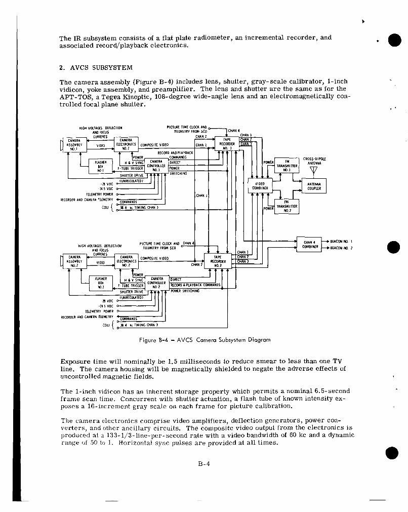
The IR subsystem consists of a flat plate radiometer, an incremental recorder, and associated record/playback electronics.
2. AVCS SUBSYSTEM
The camera assembly (Figure B-4) includes lens, shutter, gray-scale calibrator, 1-inch vidicon, yoke assembly, and preamplifier. The lens and shutter are the same as for the APT-TOS, a Tegea Kinoptic, 108-degree wide-angle lens and an electromagnetically con- - .
trolled focal pl&e shutter.
HIGH VOLTAGES. DEFLECTION PICIURE TIME CLOCK AND - AND IKUS lLLEMtTRY FRM SCO
ItLtMtIRY POWER RtCORDtR AND CAMERA IE l fMLIRY
PICTUN I lMt CLOCK AND CHIN 4 I t lEMCIRV F R M SCO HlGH VOI IAG~S DULtCItON I
AND FOCUS 1 1 C M P O S l I t VIDEO
t L ~ c ~ ~ c S No. 2
-21 I VDC A l l lLM1RV POWR
RtCORDtR AND C A M l R A l F L M I R V
CDU { lJ 4 - I C l l M l N G CHAN 3
4 4 CHAN 3
BEACON
BEACON
No. I
m?. 2
Figure 8-4 - AVCS Camera Subsystem Diagram
Exposure time will nominally be 1.5 milliseconds to reduce smear to less than one TV line. The camera housing will be magnetically shielded to negate the adverse effects of uncontrolled magnetic fields.
The 1-inch vidicon has an inherent storage property which permits a nominal 6.5-second frame scan time. Concurrent with shutter actuation, a flash tube of known intensity ex- poses a 16-increment gray scale on each frame for picture calibration.
?he camera electronics comprise video amplifiers, deflection generators, power con- verters, and other ancillary circuits. The composite video output from the electronics is produced at a 133-1/3-line-per-second rate with a video bandwidth of 60 kc and a dynamic range o f 50 to 1. Horizontal sync pulses are provided at all times.
B-4
A nominal frame of video comprises 0.25 seconds of blanked video followed by 6.25 sec- onds of vidicon scan video (833 lines) and a final 0.25-period of blanked video.
A precise flutter and wow correction tone is generated to permit compensation for the vagaries of the tape recorders in the system when the final picture presentation is made. This flutter and wow tone is gated so as to appear only during the nominal frame time, thereby acting as a "vertical sync."
Upon command to playback, the tape recorder runs in the opposite direction from re- cording. A s a result, the first picture recorded in the CDA station is the last picture taken by the camera.
Two tape recorders will be carried; to afford cross-strapped redundancy the track assign- ments on both are the same, with inputs paralleled. Track 1 records camera 1 output; track 2 records camera 2 output; track 3 records flutter and wow tone; and track 4 re- cords a frame of picture time code and commutated telemetry.
F M recording of video is accomplished by applying the 60-kc video baseband to the input of a voltage controlled oscillator (VCO) with center frequency at 192 kc, maximum devia- tion *48 kc. Since it is inefficient to record this high a frequency spectrum, the VCO output is divided by two before recording. On playback the video modulated FM signal with spectrum limited to a maximum of 120 kc is not doubled to its original state until it reaches the ground station. This not only conserves RF spectrum on transmission, but affords a more efficient communications link.
The flutter and wow tone is recorded as a 38.4-kc unmodulated signal. On playback it is divided by four to 9.6 kc to permit multiplexing with the video for transmission.
To record a frame of time and telemetry, the output of the appropriate telemetry sub- carr ier oscillator (SCO) is recorded in a manner similar to that of the picture data re- cording. Upon playback, the tape recorder output is demodulated onboard, thus recover- ing the original SCO signal. This signal is then transmitted to ground via the telemetry transmitter simultaneously with transmission of video data via the AVCS transmitter.
The camera controller accepts power and timing inputs from the programmer and CDU, processing them for distribution throughout the AVCS. The controller also processes telemetry signals before they are fed to the telemetry commutator. A video combiner permits cross-strapping redundant camera/tape recorders with the redundant transmitters.
The AVCS transmitter accepts multiplexed video subcarrier and flutter and wow tone from the video tape recorder and radiometric data from the IR recorder. It is deviated a maximum of *125 kc at a carrier frequency of 235.000 Mc. Transmission bandwidth will be a maximum of 500 kc. Including the between-picture gap, a nominal transmis- sion time of 10 seconds for each recorded picture will be required. On interrogation after a blind orbit, 24 pictures will be recorded, requiring a 4-minute playback. The tape recorder can be read out between picturetaking cycles without losing a picture or interrupting a sequence.
Direct pictures (recorder VCO output before recording) may be obtained for diagnostic purposes through this transmitter link also.
Six or twelve AVCS pictures per orbit may be programmed at 40 spin (260 second) inter- vals. The 833-line pictures at nominal altitude and attitude will cover an area of 1700 nm
B- 5
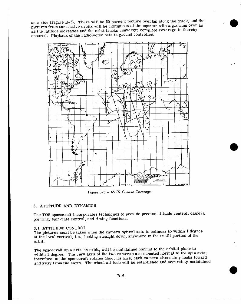
on a side (Figure B-5). There will be 50 percent picture overlap along the track, and the pictures from successive orbits will be contiguous at the equator with a growing overlap as the latitude increases and the orbit tracks converge; complete coverage is thereby ensured. Playback of the radiometer data is ground controlled.
Figure B-5 - AVCS Camera Coverage
3. ATTITUDE AND DYNAMICS
The TOS spacecraft incorporates techniques to provide precise attitude control, camera pointing, spin-rate control, and timing functions.
3.1 ATTITUDE CONTROL The pictures must be taken when the camera optical axis is colinear to within 1 degree of the local vertical, i.e., looking straight down, anywhere in the sunlit portion of the orbit.
The spacecraft spin axis, in orbit, will be maintained normal to the orbital plane to within 1 degree. The view axes of the two cameras are mounted normal to the spin axis; therefore, as the spacecraft rotates about its axis, each camera alternately looks toward and away from the earth. The wheel attitude will be established and accurately maintained
B- 6
with the quarter-orbit magnetic attitude control (QOMAC), magnetic bias control (MBC), and nutation dampers.
.
QOMAC uses a current-carrying coil to generate a controlled magnetic field which inter- acts with the earth's magnetic field to torque the spinning spacecraft. The programmer, after instructions from the ground station, reverses the direction of the current of the current in the coil each quarter orbit. The phasing of these switching points w i l l be con- trolled so that for over half an orbit the nominal average torque axis position and direc- tion of torque are controllable.
MBC will be used to eliminate any unwanted spin axis drift in orbit; MBC will null the spacecraft's residuai dipoie moment am? corr?pe~satp for the effects of the regressing orbit, thereby reducing the number of QOMAC cycles required for station keeping. The magnitude and polarity of the dipole compensations afforded by Ml3C is controlled from the ground by command.
An effective nutation damping system will be provided to rapidly reduce any imparted nutation to a negligible value. Two tuned energy-absorbing mass (TEAM) dampers will rapidly reduce any nutation cone ha l f angle to a value below 0.7 degree. A liquid damper will maintain the nutation angle at a level of the order of 0.2 degree. A low nutation angle is desired for accuracy of camera aiming and for facilitating the processing of data from the V-head horizon sensor.
3.2 ATTITUDE DETERMINATION AND CAMERA TRIGGER
3.2.1 V-HEAD HORIZON SENSORS For satisfactory picture taking, the spin axis must be maintained normal to the orbit plane and the camera shutter must be triggered at the desired instant in the rotation. Spin axis attitude is determined from telemetry of outputs from both channels of the attitude horizon sensor ( A B ) and from a telemetered digital solar aspect indicator (DSAI) output. Telemetered data from the horizon crossing indicator (HCI) may also be used to derive attitude data. The solar aspect sensor is most useful in initial maneuvers when both channels of the V-head sensor do not intersect the earth, or in the event of failure Of one of the V-head elements. When the V-head scanner data is used and nutation is allowed for, the uncertainty in roll and yaw at t ime of shutter should be less than 0.5 degree.
The AHS contains two infrared bolometers with optical axes in a V-configuration (Figure B-6). The optical paths of the sensors may intersect with the earth as the spacecraft spins; measurement of the earth-sky t ime ratios between the pulses is used to determine spin axis attitude. The digital solar aspect indicator produces a code indicative of the solar aspect angle once each rotation of the spacecraft. Resolution is 1 degree over a 128-degree range.
Data from the AHS will be transmitted continuously, in real time, on two of the three SCO's of the telemetry transmitter, each channel of the AHS on its own SCO. DSAI will be timeshared on the third SCO with the HCI and other functions.
3.2.2 HORIZON CROSSING INDICATORS (HCI) Separate infrared horizon crossing indicator (HCI) sensors are used to trigger the camera shutter (Figure B-7). The HCI's have view axes normal to the spin axis; a pair is mounted with view axes 180 degrees apart and interconnected so that only the leading edge of the sky-earth transition is controlling.
B-7
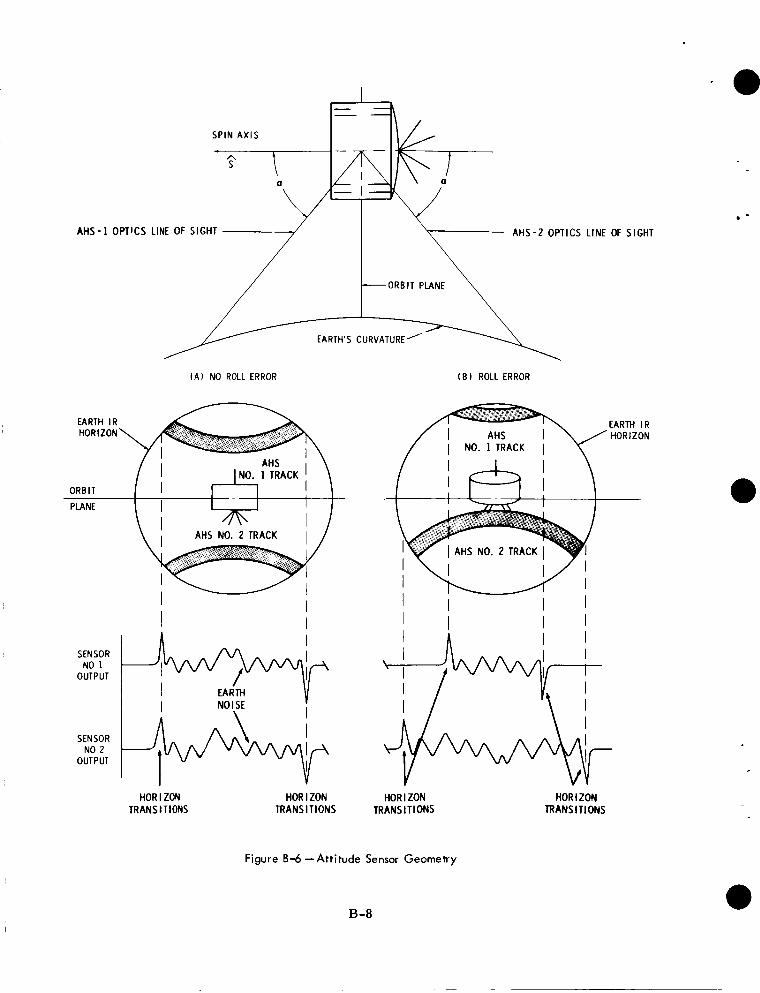
S P I N A X I S
T L -
A H S - 2 OPTICS LINE OF SIGHT
- ORBIT PLANE ':= ** EARTH'S CURVATURE'
( A ) NO ROLL ERROR
EARTH I R HORIZON
AHS NO. 2 TRACK
I
SENSOR NO 1
OUTPUT
I I NOISE I
I SENSOR NO 2
OUTPUT
HORIZON TRANSITIONS
HOR I ZON TRANSITIONS
( B ROLL ERROR
EARTH I R H O R I Z O N
HS NO. 2 TRAC
I I I I A I I
I
HOR I ZON TRANSITIONS
Figure 8-6 -Attitude Sensor Geometry
B-8
HORIZON TRANSITIONS
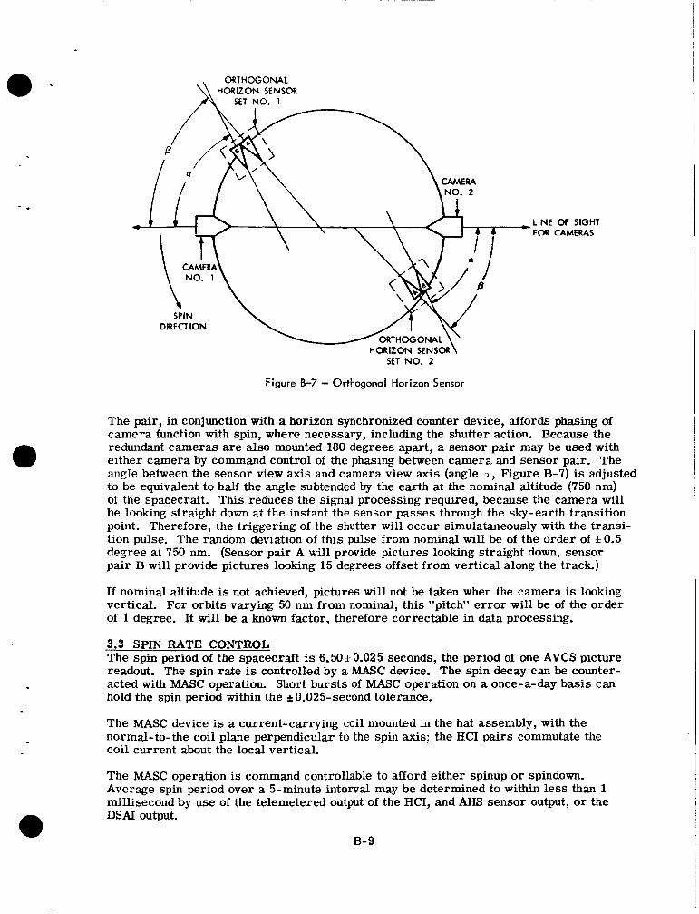
ORTHOGONAL HORIZON SENSOR 1 SET NO. 1
,LINE OF SIGHT FOa CAMERAS
HORIZON SENSOR\ SET NO. 2
Figure 8-7 - Orthogonal Horizon Sensor
The pair, in conjunction with a horizon synchronized counter device, affords phasing of camera function with spin, where necessary, including the shutter action. Because the redundant cameras are also mounted 180 degrees apart, a sensor pair may be used with either camera by command control of the phasing between camera and sensor pair. The angle between the sensor view axis and camera view axis (angle a , Figure B-7) is adjusted to be equivalent to half the angle subtended by the earth at the nominal altitude (750 nm) of the spacecraft. This reduces the signal processing required, because the camera will be looking straight down at the instant the sensor passes through the sky-earth transition point. Therefore, the triggering of the shutter will occur simulataneously with the transi- tion pulse. The random deviation of this pulse from nominal will be of the order of & 0.5 degree at 750 nm. (Sensor pair A will provide pictures looking straight down, sensor pair B will provide pictures looking 15 degrees offset from vertical along the track.)
If nominal altitude is not achieved, pictures wil l not be taken when the camera is looking vertical. For orbits varying 50 nm from nominal, this "pitch" error will be of the order of 1 degree. It will be a known factor, therefore correctable in data processing.
3.3 SPIN RATE CONTROL The spin period of the spacecraft is 6.50 +0.025 seconds, the period of one AVCS picture readout. The spin rate is controlled by a MASC device. The spin decay can be counter- acted with MASC operation. Short bursts of MASC operation on a once-a-day basis can hold the spin period within the lt0.025-second tolerance.
The MASC device is a current-carrying coil mounted in the hat assembly, with the normal-to-the coil plane perpendicular to the spin axis; the HCI pairs commutate the coil current about the local vertical.
The MASC operation is command controllable to afford either spinup or spindown. Average spin period over a 5-minute interval may be determined to within less than 1 millisecond by use of the telemetered output of the HCI, and AHS sensor output, or the DSAI output.
B- 9
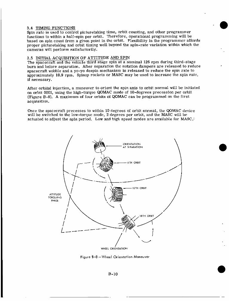
3.4 TIMING FUNCTIONS Spin rate is used to control picturetaking time, orbit counting, and other programmer functions to within a half-spin per orbit. Therefore, operational programming will be based on spin count from a given point in the orbit. Flexibility in the programmer affords proper picturetaking and orbit timing well beyond the spin-rate variation within which the cameras will perform satisfactorily.
3.5 INITIAL ACQUISITION OF ATTITUDE AND SPIN The spacecraft and the vehicle third stage spin at a nominal 126 rpm during third-stage burn and before separation. After separation the nutation dampers a r e released to reduce spacecraft wobble and a yo-yo despin mechanism is released to reduce the spin rate to approximately 10.9 rpm. Spinup rockets or MASC may be used to increase the spin rate, i f necessary.
After orbital injection, a maneuver to orient the spin axis to orbit normal will be initiated on orbit 0001, using the high-torque QOMAC mode of 10-degrees precession per orbit (Figure B-8). A maximum of four orbits of QOMAC can be programmed on the f i rs t acquisition.
Once the spacecraft precesses to within 10 degrees of orbit normal, the QOMAC device will be switched to the low-torque mode, 2 degrees per orbit, and the MASC will be actuated to adjust the spin period. Low and high speed modes a r e available for MASC.;
/ ORIENTATION AT SEPARATION
- 6TH ORBIT
/-
\ I x ATTITUDE TORQUING
PHASE
i’\ I I L---
/ /
WHEEL ORIENTATION
Figure 8-8 -Wheel Orientation Maneuver
B- 10
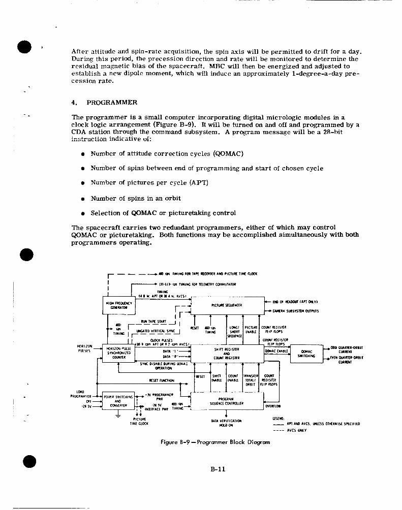
Afte r attitude and spin-rate acquisition, the spin axis will be permitted to drift for a day. During this period, the precession direction and rate will be monitored to determine the residual magnetic bias of the spacecraft. MBC will then be energized and adjusted to establish a new dipole moment, which will induce an approximately 1-degree-a-day pre- cession rate.
4. PROGRAMMER
The programmer is a small computer incorporating digital micrologic modules in a clock logic arrangement (Figure B-9). It will be turned on and off and programmed by a CDA station through the command subsystem. A program message will be a 28-hit instruc:ioii iiicficaiive of:
0 Number of attitude correction cycles (QOMAC)
0 Number of spins between end of programming and start of chosen cycle
0 Number of pictures per cycle (APT)
0 Number of spins in an orbit
0 Selection of QOMAC or picturetaking control
The spacecraft carries two redundant programmers, either of which may control QOMAC or picturetaking. Both functions may be accomplished simultaneously with both programmers operating.
C t i - PlClUilC IIkU CLOCK
1 MIA V f R l f l C A l l O N
n U D - O N
Earn: - API AUO AVCS. M f S S OTIfRWtSt SPfCIfIcD
---- AVCS ONLY
Figure 8-9 -Programmer Block Diagram
B-11
The programmer has the capability of:
0 Initiating picturetaking and attitude-correction cycles at a point remote from the CDA station. The delay is derived from s p h count and wi l l be a maximum of about 222 minutes.
0 Controlling the number of pictures to be taken on each orbit and the interval between pictures. Either a 6- or 12-picture sequence may be programmed at an interval of 260 seconds (40 spins) between pictures.
0 Turning camera power off at the end of a sequence, and restarting the cycle in the next orbit. Therefore, the orbit period becomes a basic timing cycle. Orbit periods which may be accommodated with nominal spin-rates will be from approxi- mately 69 minutes to 180 minutes (641 to 1684 spins). The programmer will repeat the sequence each orbit until turned off or reprogrammed by ground command.
0 Providing synchronization of spacecraft operations with the spacecraft spin-rate, automatically rephasing if synchronization is disturbed, and providing backup horizon crossing pulses if the HCI output pulses a r e interrupted, thereby permit- ting the satellite spin-rate to be a timing source. A horizon sync counter is synchronized to the sky-earth transition pulse output of the orthogonal horizon sensor. It discriminates against earth noise pulses which may follow this leading edge pulse by means of a gating operation using outputs from the HCI. The output is one pulse per spin of the spacecraft, generated in phase with the output of the HCI associated with the camera being used. Perfect synchronization will be afforded with spin periods varying from 5.12 seconds up to 100 milliseconds longer than the nominal 6.5-seconds spin. l
0 Providing quarter-orbit timing and control of number of cycles for QOMAC opera- a tion. In the QOMAC mode the programmer is not synchronized to horizon pulses, because the horizon sync counter is programmed to operate in a free running mode a t the nominal spin rate. This is necessary because in the initial orientation maneu- vers immediately after launch the orthogonal horizon sensors do not see the earth. Quarter-orbit periods which may be accommodated a r e from 28 to 56 minutes.
0 Providing synchronized control of the camera subsystems. The outputs of the programmer supply the camera with horizontal sync, vertical sync, power control, shutter and flash tube trigger pulses, gated timing signals, and tape recorder control.
5. COMMAND SUBSYSTEM
The command subsystem comprises two redundant fixed-tuned AM receivers/tone detec- tors and decoder units. The receiver and tone detectors operate continuously, while the decoder is powered upon receipt of a particular enable tone, different for each of the redundant decoders. After enabling, a digital spacecraft address is transmitted, followed by the digital command. The outputs of the redundant decoders appear on matrices which a r e ORed in the CDU before distribution. When a load programmer command is received and is followed by a normal bit stream, the system stays open until the programmer is completely filled.
'
If the signal drops out for a short period, o r if a suitable spacecrak address is not re- ceived within a given period, the decoder power is removed and the subsystem reverts to a standby condition. Receipt of an improper code causes the decoder registers to reset.
B- 1 2
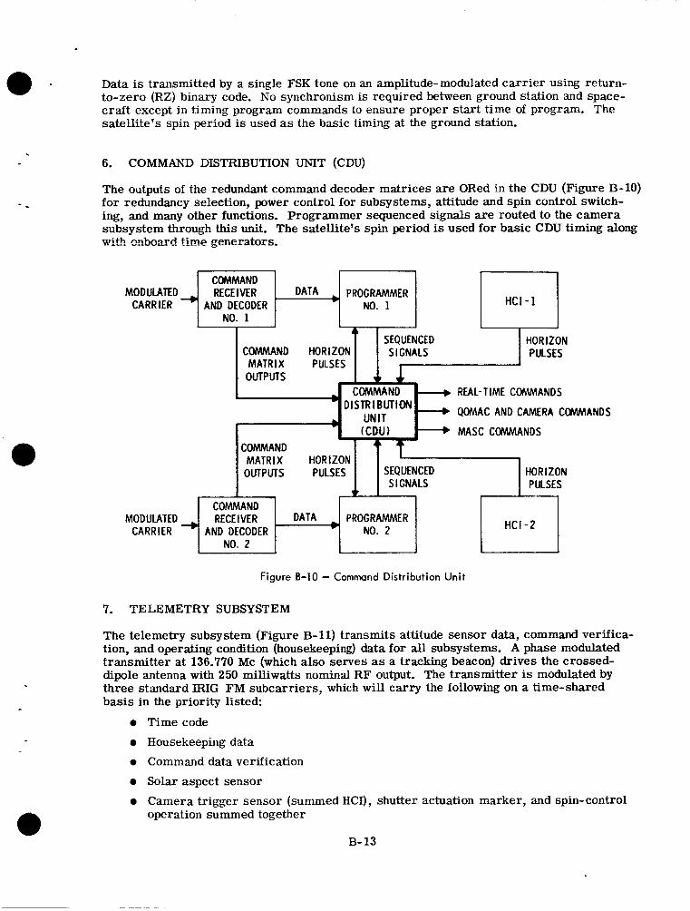
Data is transmitted by a single FSK tone on an amplitude-modulated carrier using return- to-zero (RZ) binary code. No synchronism is required between ground station and space- craft except i n timing program commands to ensure proper start time of program. The satellite's spin period is used as the basic timing at the ground station.
..
6. COMMAND DISTRIBUTION UNIT (CDU)
The outputs of the redundant command decoder matrices are ORed in the CDU (Figure B-10) for redundancy selection, power control for subsystems, attitude and spin control switch- ing, and many other functions. Programmer sequenced signals are routed to the camera subsystem through this unit. The satellite's spin period is used for basic CDU timing along wit! mbeccd time generators.
RECEIVER 1 DATA 4 PROGRAMMER I M o D u w m ~ CARRIER AND DECODER No. 1 I NO. 1 I
I HCI-1 I
REAL-TIME COMMANDS
QOMAC AND CAMERA COMMANDS
MASC COMMANDS
OUTPUTS MATRIX H:$z I I S E i Y l HORIZON I - - S I GNALS PULSES
COMMAND MODULATED 4 RECEIVER 1 DATA 4 PROGRAMMER 1
CARRIER AND DECODER No. 2 u I NO. 2 1 ~ HCI -2
Figure B-10 - Command Distribution Unit
7. TELEMETRY SUBSYSTEM
The telemetry subsystem (Figure B-11) transmits attitude sensor data, command verifica- tion, and operating condition (housekeeping) data for all subsystems. A phase modulated transmitter at 136.770 Mc (which also serves as a tracking beacon) drives the crossed- dipole antenna with 250 milliwatts nominal RF output. The transmitter is modulated by three standard B I G FM subcarriers, which will carry the following on a time-shared basis in the priority listed:
0 Timecode
0 Housekeeping data
0 Command data verification
0 Solar aspect sensor 0 Camera trigger sensor (summed HCI), shutter actuation marker, and spin-control
operation summed together
B- 13
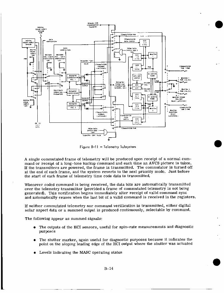
I
01 I O H C I O I l A
I U I C M I M I
Figure B-11 - Telemetry Subsystem
A single commutated frame of telemetry will be produced upon receipt of a normal com- mand o r receipt of a long-tone backup command and each time an AVCS picture is taken. If the transmitters are powered, the frame is transmitted. The commutator is turned off at the end of each frame, and the system reverts to the next priority mode. Just before the start of each frame of telemetry time code data is transmitted.
Whenever coded command is being received, the data bits are automatically transmitted over the telemetry transmitter (provided a frame of commutated telemetry is not being generated). This verification begins immediately after receipt of valid command sync and automatically ceases when the last bit of a valid command is received in the registers.
If neither commutated telemetry nor command verification is transmitted, either digital solar aspect data or a summed output is produced continuously, selectable by command.
The following appear as summed signals:
0 The outputs of the HCI sensors, useful for spin-rate measurements and diagnostic purposes
0 The shutter marker, again useful for diagnostic purposes because it indicates the point on the sloping leading edge of the HCI output where the shutter was actuated
0 Levels indicating the MASC operating status
B- 14
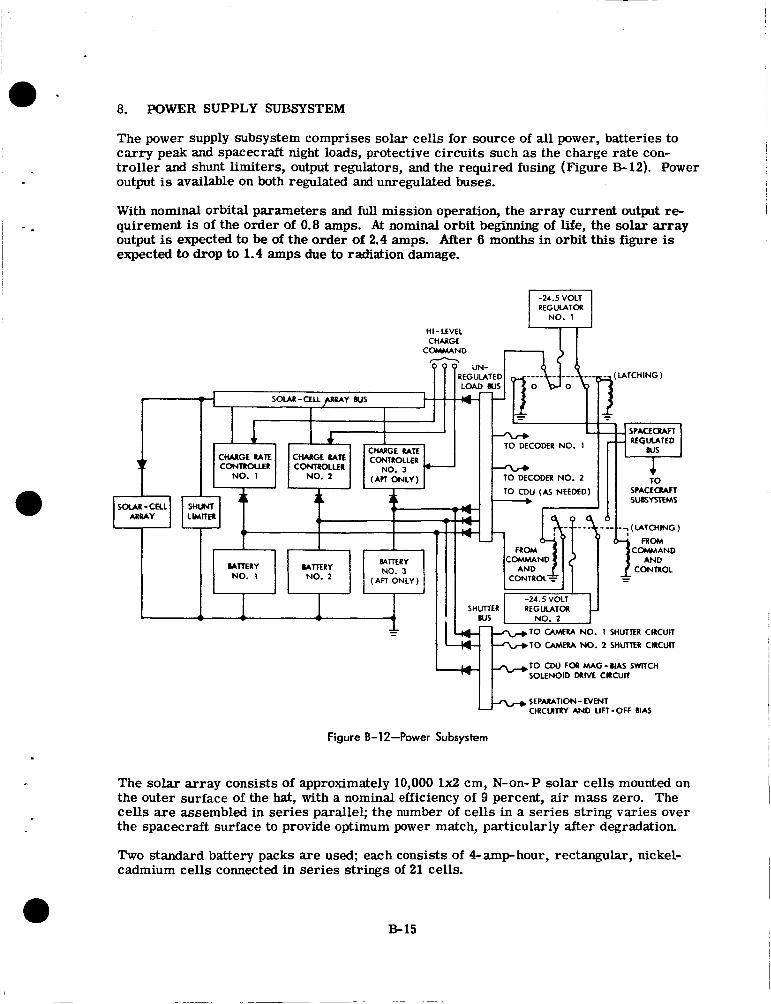
I - c
8. POWER SUPPLY SUBSYSTEM
The power supply subsystem comprises solar cells for source of all power, batteries to carry peak and spacecraft night loads, protective circuits such as the charge rate con- troller and shunt limiters, output regulators, and the required fusing (Figure €3-12). Power output is available on both regulated and unregulated buses.
With nominal orbital parameters and full mission operation, the array current output re- quirement is of the order of 0.8 amps. At nominal orbit beginning of life, the solar array output is expected to be of the order of 2.4 amps. After 6 months in orbit this figure is expected to drop to 1.4 amps due to radiation damage.
-24.5 VOLT REGULATOR NO. 1
HI-LEVEL CHARGf
COMMAND
TO DECODER NO. 1
TO CAMERA NO. 1 SHUTTER cmcum TO CAMEU NO. 2 SHUTTER ClRCUll
TO C W FOR MAG-MAS SWITCH SOLENOID DUNE CRCLJK
SEPARATION- EVENT 14L* CiRCUllRY AND UIT-OFF BIAS
Figure B-12-Power Subsystem
The solar array consists of approximately 10,000 1x2 cm, N-on-P solar cells mounted on the outer surface of the hat, with a nominal efficiency of 9 percent, air mass zero. The cells are assembled in series parallel; the number of cells in a series string varies over the spacecraft surface to provide optimum power match, particularly after degradation.
Two standard battery packs are used; each consists of 4-amphour, rectangular, nickel- cadmium cells connected in series strings of 21 cells.
B- 15
, Protection is afforded by shunt limiters on the array output and charge-rate controllers, which maintain the array output voltage below a safe level of -33 volts. A charge-rate controller associated with each battery pack, commandable to a normal charge rate of 400-milliamp per battery pack o r to a 50 percent higher charge rate.
A regulated output bus is provided at 24.5 f 0.5 volts. Redundant regulators a r e provided, switchable upon command, The regulator receives its input from the regulated bus and has a 5- amp output capability.
A separate unregulated bus will also be used for high, momentary loads, such as for shutters, isolating these transient loads. Current for the unregulated bus is supplied by the solar array and batteries in a parallel arrangement. In orbit daytime, the solar array furnishes power for both battery charging and system loads. The batteries supply addi- tional power for high peak loads and orbit nighttime.
I
9. SPACECRAFT COMMUNICATIONS I
Three spacecraft/ground station communication links are used in TOS APT. Commands a r e transmitted by means of a 250-w minimum output AM transmitter and a 9-db minimum gain, circularly polarized, tracking antenna at the CDA station. The spacecraft command
and modulation tones will be used for all spacecraft since each will have a unique address code. With nominal attitude and altitude and 5-degree tracking antenna elevation, this system will have an operating margin of the order of 9 db.
The crossed-dipole antenna used for telemetry transmissions and as a tracking beacon is omnidirectional t o within nominally f 6 db. It transmits 136.770- MC 250-mw PM signal continuously, but may be turned on and off by command.
All TOS AVCS spacecraft will use 5-w F M transmitters at 235.000 Mc. Transmission bandwidth will be of the order of 500 kc. Sleeves on the crossed-dipole antennas will afford transmission capability at this frequency. The pattern is omnidirectional to within 56 db. The transmitter will be radiating only during AVCS tape recorder playback and when requesting a direct picture, nominally 2 to 4 minutes each orbit.
I reception antenna is the monopole at the top of the hat. The same command radio frequency
I
I
B-16
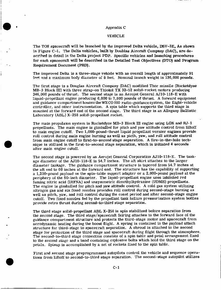
Appendix C
VEHICLE
The TOS spacecraft will be launched by the improved Delta vehicle, DSV-3E, A s shown in Figure C-1. The Delta vehicles, built by Doublas Aircraft Company (DAC), are de- scribed in detail in the Delta project PDP. Specific vehicles and launching procedures for each spacecraft will be described in the Detailed Test Objectives (DTO) and Program Requirement Document (PRD) . The improved Delta is a three-stage vehicle with an overall length of approximately 91 feet and 2 F~~YLEY.~ k d q ' dkiji&ei= oi 8 feet. Nommal launch weight is 136,000 pounds.
The first stage is a Douglas Aircraft Company (DAC) modified Thor missile (Rocketdyne MB-3 Block III) with three strap-on Thiokol TX 33-52 solid-rocket motors producing 346,000 pounds of thrust. The second stage is an Aerojet General AJ10-118-E with liquid-propellant engine producing 6,000 to 7,800 pounds of thrust. A forward equipment and guidance compartment houses the WECO 600 radio-guidance system, the flight-vehicle controller, and other instrumentation. A spin table which supports the third stage is mounted at the forward end of the second stage. The third stage is an Allegany Ballistic Laboratory (ABL) X-258 solid-propellant rocket.
The main propulsion system is Rocketdyne MB-3 Block 111 engine using LOX and RJ-1 propellants. The main engine is gimballed for pitch and yaw attitude control from liftoff to main engine cutoff. Two 1,000-pound-thrust liquid propellant vernier engines provide roll control during main engine burning as well as picth, yaw, and roll attitude control from main engine cutoff t o first-to-second stage separation. A fire-in-the-hole tech- nique is utilized in the first-to-second stage separation, which is initiated 4 seconds after main engine cutoff.
The second stage is powered by an Aerojet General Corporation AJ10-118-E. The tank- age diameter of the AJ10-118-E is 54.7 inches. The aft skirt attaches to the larger diameter tankage. The guidance compartment structure is tapered from 54.7 inches at the aft end to 60 inches at the forward end. The structure has the capability of supporting a 1,200-pound payload on the spin-table support adapter or a 2,000-pound payload at the periphery of the 60-inch diameter. The liquid-propellant engine uses inhibited red fuming nitric acid (IRFNAJ and unsymmetric dimethylhydrazine (UDMH) propellants. The engine is gimballed for pitch and yaw attitude control. A cold gas system utilizing nitrogen gas and six fixed nozzles provides roll control during second-stage burning as well as pitch, yaw, and roll control during the coast period and after second-stage engine cutoff. Two fixed nozzles fed by the propellant tank helium pressurization system bottles provide retro thrust during second-to-third stage separation.
The third stage solid-propellant ABL X-258 is spin stabilized before separation from the second stage. The third stage/spacecraft fairing attaches to the forward face of the guidance compartment structure and protects the third-stage motor and spacecraft from aerodynamic heating during the boost flight. A spring is contained in the payload attach structure for third-stage to spacecraft separation. A shroud is attached to the second stage for protection of the third stage and spacecraft during flight through the atmosphere. The second-to-third stage connection consists of a spin table and petal arrangement fixed to the second stage and a band containing explosive bolts which hold the third stage on the petals. Spinup is accomplished by a set of rockets fixed to the spin table.
First and second stage preprogrammed autopilots control the vehicle and sequence opera- tions from liftoff to second-to-third stage separation. The second-stage autopilot utilizes
c- 1
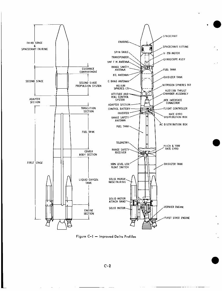
ADAPTER SECTION
TRANSITION
FIRST
TAGE I I SECTION
BODY SECTION hR
A ,SPACECRAFl
SPACECRAFT FITTING
GYROSCOPE ASSY VHF T M ANTEN
OXIDIZER TANK C BAND ANTENNA
NITROGEN SPHERES (6)
AJlO 118E THRUST ATTITUDE AND CHAMBER ASSEMBLY ROLL CONTROL
J921 INTERFACE
FLIGHT CONTROLLER
C DISTRIBUTION BOX
I H I
\ TELEMETRY
RANGE SAFETY RATE GYRO RECEIVER
lOU5 LEVEL LOX’ OXIDIZER TANK FLOAT SWITCH
SOLID MOTOR
VERNIER ENGINE
FIRST STAGE ENGINE
Figure C-1 - Improved Delta Profiles
c-2
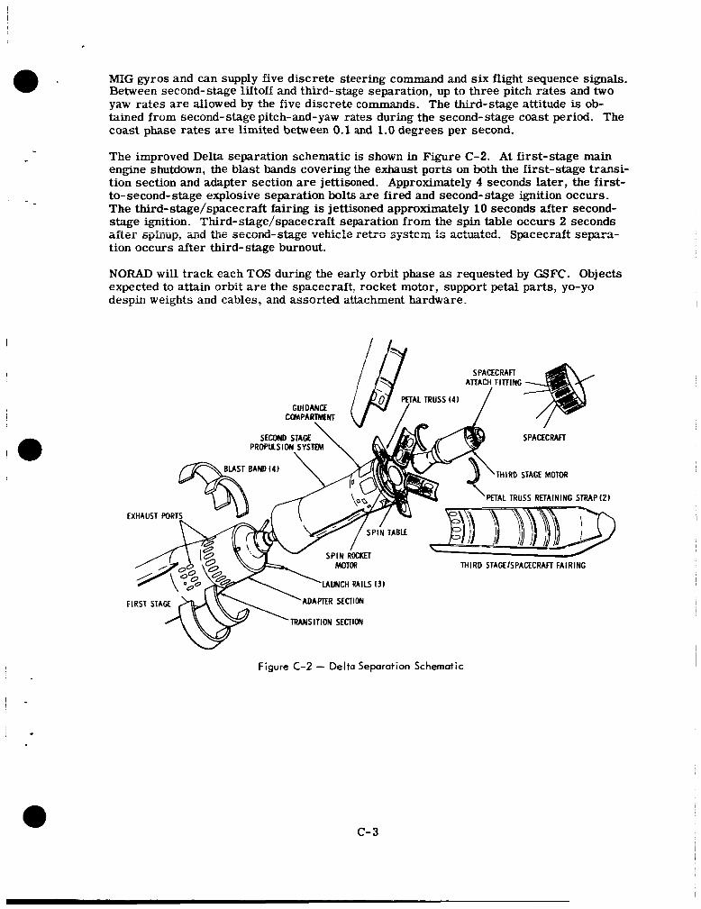
MIG gyros and can supply five discrete steering command and six flight sequence signals. Between second-stage liftoff and third-stage separation, up to three pitch rates and two yaw rates are allowed by the five discrete commands. The third-stage attitude is ob- tained from second-stage pitch-and-yaw rates during the second-stage coast period. The coast phase rates are limited between 0.1 and 1.0 degrees per second.
~
The improved Delta separation schematic is shown in Figure C-2. At first-stage main engine shutdown, the blast bands covering the exhaust ports on both the First-stage transi- tion section and adapter section are jettisoned. Approximately 4 seconds later, the first- to-second-stage explosive separation bolts are fired and second-stage ignition occurs. The third-stage/spacecraft fairing is jettisoned approximately 10 seconds after second- stage ignition. Third-stage/spacecraft separation from the spin table occurs 2 seconds after- spinup, aid L\e aecofid-a't.--e ve?iz?e retra sq'stclm is actaatcd. Spcecra€t separa- tion occurs after third-stage burnout.
NORAD will track each TOS during the early orbit phase as requested by GSFC. Objects expected to attain orbit a r e the spacecraft, rocket motor, support petal parts, yo-yo despin weights and cables, and assorted attachment hardware.
SPACECRAFI ATTACH FITTING 1
SECOND STAGE PROPUSION SYSTEM
\
PETAL TRUSS (4 ) GUIDANCE
C O M P A R l M N l \
THIRD STAGE MOTOR BLAST BAND (4) \
EXHAUST PORTS
FIRST S T A R
%
-. . . . . ._ -. -. c MOTOR THIRD STAGEISPACECRAFT FAIRING
'LAUNCH RAILS 13)
ADAPTER SECTION
TRANSITION SECTION
Figure C-2 - Delto Separation Schematic
c- 3
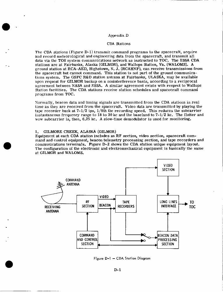
Appendix D
COMMAND ANTENNA
CDA Stations
VIDEO RF
RECEIVING SECTION Bacot - ANTENNA
The CDA stations (Figure D-1) transmit command programs to the spacecraft, acquire and record meteorological and engineering data from the spacecraft, and transmit all data via the TOS system communications network as instructed to TOC. The ESSA CDA stations are at Fairbanks, Alaska (GILMOR), and Wallops Station, Va. (WALOMS). A ground station at RCA-AED, Highstown, N. J. (RCAHNF), can receive transmissions from the spacecraft but cannot command. This station is not part of the ground communica- tions system. The GSFC R&D station antenna at Fairbanks, ULASKA, may be available upon request for GILMOR backup on a noninterference basis, according to a reciprocal agreement between NASA and ESSA. A similar agreement exists with respect to Wallops Station facilities. The CDA stations receive station schedules and spacecraft command programs from TOC.
Normally, beacon data and timing signals are transmitted from the CDA stations in real time as they a re received from the spacecraft. Video data are transmitted by playing the tape recorder back at 7-1/2 ips, 1/8th the recording speed. This reduces the subcarrier instantaneous frequency range to 18 to 30 kc and the baseland to 7-1/2 kc. The flutter and wow subcarrier is, then, 6.25 kc. A slow-time demodulator is used for monitoring.
TAPE LONG LINES + TO RECORDERS INTERFACE TOC
1. GILMORE CREEK, ALASKA (GILMOR) Equipment at each CDA station includes an R F section, video section, spacecraft com- mand and control equipment, beacon telemetry processing section, and tape recorders and communications terminals. Figure D-2 shows the CDA station unique equipment layout. The configuration of the electronic and electromechanical equipment is basically the same at GILMOR and WALOMS.
4
C O W A N D AND CONTROL
4
BEACON DATA > PROCESSING
Figure D-1 - CDA Station Diagram
SECTION 4 +I
D- 1
SECTION
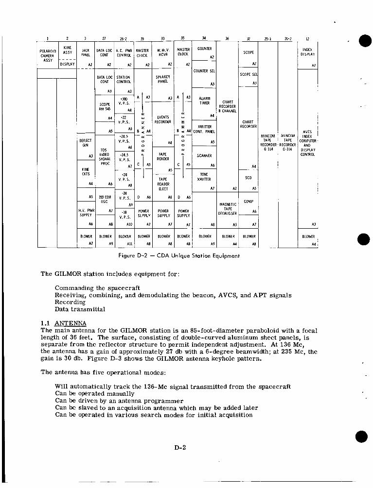
CAMERA
3 -
JACK PANEL
A 2
- DEFLECT
CEN
A3 - KINE CKTS
A 4 -
As -
I.V. PWF SUPPLY
A 6
BLOWER
A 7
COUNTER SEI
IATA LOC STATION SPEAKER CON1 I CONTROL 1 I PANEL 1 I A3
I I I I -Flw R M 545 TIMER
5
TOS VIDEO
PROC READER
A5 A 7 A 5
+24 TONE v. P. s. TAPE X M I l l E R
*I SUPPLY SUPPLY
A 8 1 A I 0 1 MI A71 A71 1 A 9 A l l
BLOWER BLOWER BLOWER BLOWER BLOWER BLOWER
36
CHART RECORDER 8 CHANNEL
A2
MAGNETIC TAPE
DEGAUSSER
A3
BLOWER
A4
32 ~
SCOPE
A2
L O P E SE
A3
-
CHART ZECORDEF
A 4 -
SCD
A5
COMP
A b
A 7 -
BLOWER
AB
a- 1 ~
M I N C O M TAPE
ZECORDER 6-114
20-2 ~
M I N C O M TAPE
'ECORDER G-114
~
Figure D-2 - CDA Unique Station Equipment
The GILMOR station includes equipment for:
Commanding the spacecraft Receiving, combining, and demodulating the beacon, AVCS, and APT signals Recording Data transmittal
12
INDEX DISPLAY
A 2
~
-
AVCS INDEX
:OMPUTER AND
D I S P L A Y CONTROL
A3 -
BLOWER
A 4 ~
1.1 ANTENNA The main antenna for the GILMOR station is an 85-foot-diameter paraboloid with a focal length of 36 feet. The surface, consisting of double-curved aluminum sheet panels, is separate from the reflector structure to permit independent adjustment. At 136 Mc, the antenna has a gain of approximately 27 db with a 6-degree beamwidth; at 235 Mc, the gain is 30 db. Figure D-3 shows the GILMOR antenna keyhole pattern.
The antenna has five operational modes:
Will automatically track the 136-Mc signal transmitted from the spacecraft Can be operated manually Can be driven by an antenna programmer Can be slaved to an acquisition antenna which may be added later Can be operated in various search modes for initial acquisition
D- 2
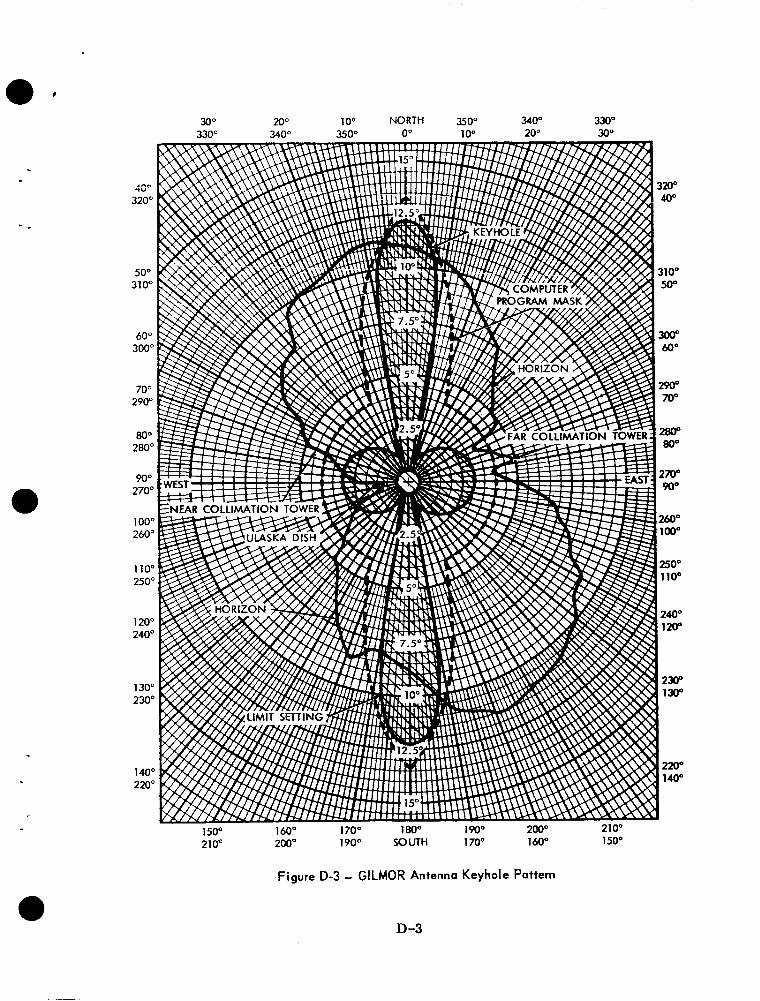
30" 200 10" NORTH 350" 340" 330" 0" 1 0" 20" 30"
Figure D-3 - GILMOR Antenna Keyhole Pattern
D-3
The antenna reflector is mounted on an X-Y mount designed specifically for tracking spacecraft, with the advantage that there are no gimbal-lock positions in the sky area above the horizon. This permits optimum tracking of spacecraft without requiring ex- cessive shaft velocities from the antenna-drive system.
Antenna feeds will have a monopulse autotrack capability on 136 Mc and 1700 Mc. The multifrequency antenna-feed cluster consists of two separate systems; a set of four crossed dipoles for the 136-Mc to 137-Mc band, and a set of four crossed dipoles for the 1700-Mc band. Standard monopulse circuitry with coaxial hybrids obtains the sum- channel and tracking-channel outputs from the array of four dipoles.
The feed system permits the antenna control operator to switch-select any of four polari- zation senses for reception of 136-Mc signals (two linear and two orthogonal circular).
Antenna polarization will be righthand circular. The best circular should be selected for tracking, but only when data is not being transmitted.
1.2 RF SECTION R F equipment includes receiving, combining, and demodulating equipment for beacon, AVCg and APT signals, and command transmitting equipment.
During the prelaunch phase, T&DS will conduct engineering tests of the TOS ground station equipment. These tests will be the basis for the prepass tes ts that will be run at the sta-
assurance that all TOS and DAF subsystems a r e compatible and that the integration be- tween subsystems has been completed.
I tions during postlaunch operations. The purpose of these tests is to provide prelaunch
, The tests will consist of R F loop tests where calibration signal generators a re modulated with information from either satellite simulators o r magnetic tapes. Input signal levels to the RF preamplifiers will be varied in order to obtain dynamic range and threshhold data, The demodulated data will be recorded and played over the microwave links to GSFC where appropriate.
The RF equipment includes low-noise preamplifiers and down convertors. All tracking and data signals a r e translated down to the 130 to 140 Mc band. General Dynamics/ Electronics Diversity, (GD/E) telemetry receivers a r e used for all data reception. A post-detection diversity combiner provides a combining action for either the two linear or two orthogonal circular polarization. The diversity receiver has selectable IF band- widths of 10, 30, 100, 500, 1000, and 3000 kc. The 500 kc bandwidth has replaced the standard 300 kc bandwidth. An Electrac phase demodulator provides coherent place de- modulation for the beacon telemetry signal. A predetection diversity combiner provides polarization diversity. Table D-1 l ists the setup procedure for the Electrac phase de- modulation.
The setup procedures for beacon telemetry are as follows:
1. Use standard station procedure to check meter calibration for phase modulation.
2. Set the modulation sensitivity control on the CSG-1 for a peak deviation of 23 degrees using only one subcarrier. Remove this subcarrier.
3. Set the modulation for a peak deviation of 23 degrees by varying the level of the second subcarrier. Remove this subcarrier.
4. Repeat step 3 for the 3rd subcarrier.
D- 4
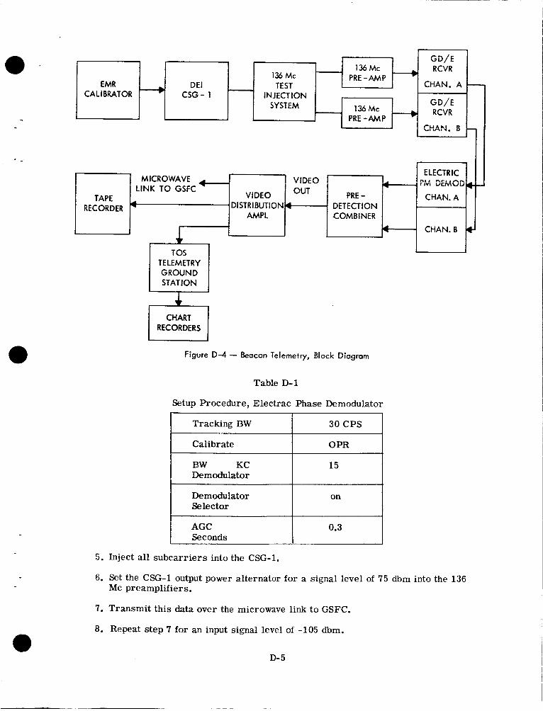
.
- 136 Mc
136 Mc PRE-AMP - EMR DEI TEST
CALIBRATOR - CSG- 1 INJECTION - SYSTEM 136 Mc
PRE - A M P - GD/E RCVR
CHAN. A - GD/E RCVR
W A N . 8 -
Figure D-4 - Beacon Telemetry, Block Diagram
1 7 MICROWAVE ’ VIDEO -4 J ::vi DEMOD 4-
Table D-1
Setup Procedure, Electrac Phase Demodulator
PRE - CHAN. A LINK TO GSFC OUT I TAPE VIDEO
RECORDER DISTRIBUTION 4 1 DETECTION AMPL COMBINER * CHAN.B 4-
I Tracking BW I 30CPS I
AGC Seconds
_____ ~~~~ I Calibrate I OPR 1
0.3
Demodulator
Demodulator + Selector
D- 5
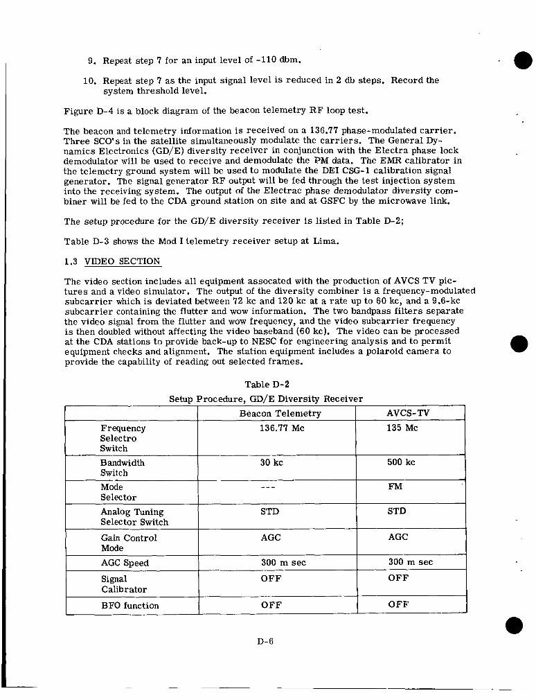
9. Repeat step 7 for an input level of -110 dbm.
10. Repeat step 7 a s the input signal level is reduced in 2 db steps. Record the system threshold level.
Figure D-4 is a block diagram of the beacon telemetry R F loop test.
The beacon and telemetry information is received on a 136.77 phase-modulated carr ier . Three SCO's in the satellite simultaneously modulate the carr iers . The General Dy- namics Electronics (GD/E) diversity receiver in conjunction with the Electra phase lock demodulator w i l l be used to receive and demodulate the PM data. The EMR calibrator in the telemetry ground system will be used to modulate the DEI CSG-1 calibration signal generator. The signal generator R F output will be fed through the test injection system into the receiving system. The output of the Electrac phase demodulator diversity com- biner will be fed to the CDA ground station on site and at GSFC by the microwave link.
Beacon Telemetry Frequency 136.77 Mc Selectro Switch Bandwidth 30 kc Switch Mode --- Selector Analog Tuning STD Selector Switch
Gain Control AGC Mode AGC Speed 300 m sec
Signal O F F Calibrator
BFO function O F F
The setup procedure for the GD/E diversity receiver is listed in Table D-2;
Table D-3 shows the Mod I telemetry receiver setup at Lima.
AVCS- TV 135 Mc
500 kc
FM
STD
AGC
300 m sec
O F F
O F F
1.3 VIDEO SECTION
The video section includes all equipment assocated with the production of AVCS TV pic- tures and a video simulator. The output of the diversity combiner is a frequency-modulated subcarrier which is deviated between 72 kc and 120 kc at a rate up to 60 kc, and a 9.6-kc subcarrier containing the flutter and wow information. The two bandpass filters separate the video signal from the flutter and wow frequency, and the video subcarrier frequency is then doubled without affecting the video baseband (60 kc). The video can be processed at the CDA stations to provide back-up to NESC for engineering analysis and to permit equipment checks and alignment. The station equipment includes a Polaroid camera to provide the capability of reading out selected frames.
D-6
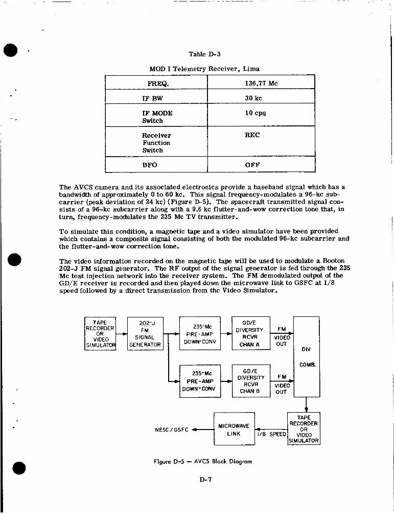
Table D-3
=Q.
IF BW
MOD I Telemetry Receiver, Lima
136.77 Mc
30 kc
Function Switch
BFO
IF MODE 10 CPS I I Switch
OFF
202-J
SIGNAL GENE RATOR
+ t
The AVCS camera and its associated electronics provide a baseband signal which has a bandwidth of approximately 0 to 60 kc. This signal frequency-modulates a 96-kc sub- carr ier (peak deviation of 24 kc) (Figure D-5). The spacecraft transmitted signal con- sists of a 96-kc subcarrier along with a 9.6 kc flutter-and-wow correction tone that, in turn, frequency-modulates the 235 Mc TV transmitter.
To simulate this condition, a magnetic tape and a video simulator have been provided which contains a composite signal consisting of both the modulated 96-kc subcarrier and the flutter-and-wow correction tone.
The video information recorded on the magnetic tape wil l be used to modulate a Booton 202-5 FM signal generator. The R F output of the signal generator is fed through the 235 Mc test injection network into the receiver system. The FM demodulated output of the GD/E receiver is recorded and then played down the microwave link to GSFC at 1/8 speed followed by a direct transmission from the Video Simulator.
G DIE
RCVR VIDEO DIVERSITY FM
CHAN A OUT
235-Mc PRE-AMP --.)
DOWN-CONV
a
235-Mc GD/E DIVERSITY F M
CHANB OUT RCVR VIDEO*
+ PRE-AMP DOWN-CONV
DIV
COME.
Figure D-5 - AVCS Block Diagram
D-7
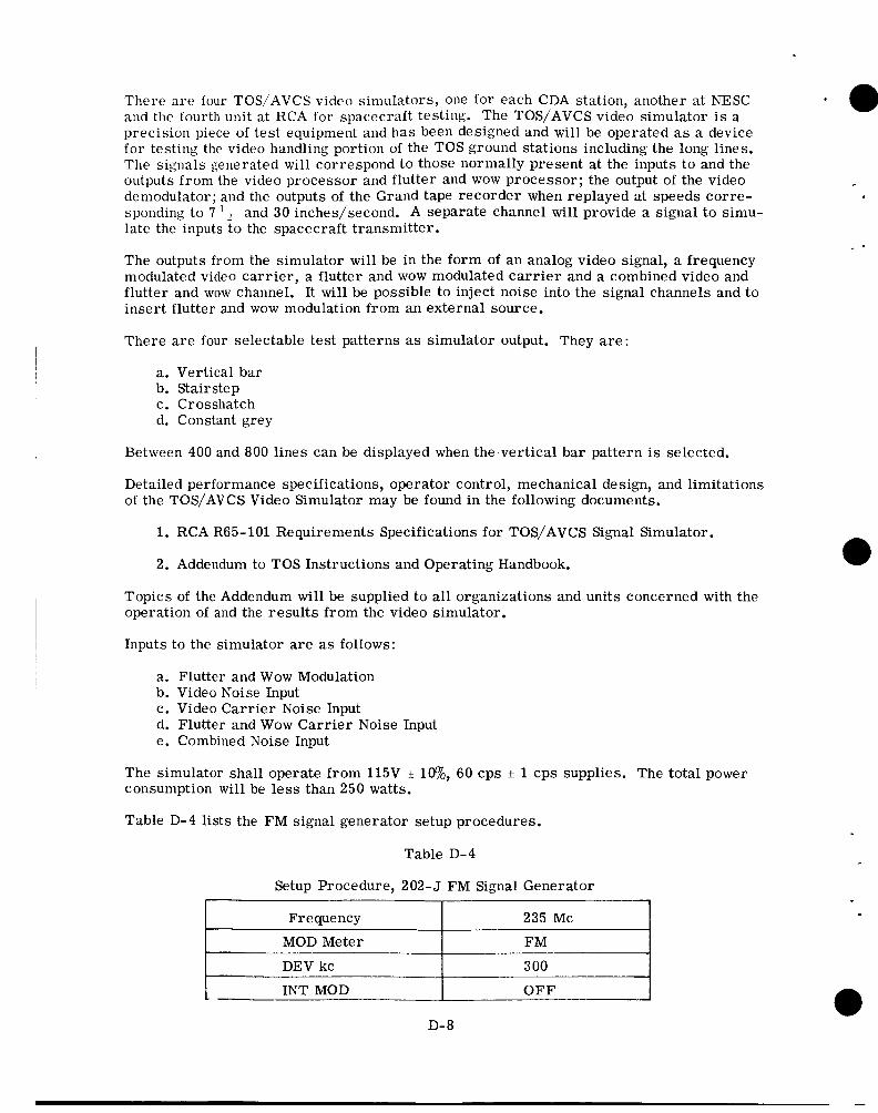
There a re four TOS/AVCS video simulators, one for each CDA station, another at NESC and the fourth unit at RCA for spacecraft testing. The TOS/AVCS video simulator is a precision piece of test equipment and has been designed and will be operated as a device for testing the video handling portion of the TOS ground stations including the long lines. The signals generated will correspond to those normally present at the inputs to and the outputs from the video processor and flutter and wow processor; the output of the video demodulator; and the outputs of the Grand tape recorder when replayed at speeds corre- sponding to 7 late the inputs to the spacecraft transmitter.
and 30 inches/second. A separate channel will provide a signal to simu-
The outputs from the simulator will be in the form of an analog video signal, a frequency modulated video carrier, a flutter and wow modulated ca r r i e r and a combined video and flutter and wow channel. It will be possible to inject noise into the signal channels and to insert flutter and wow modulation from an external source.
There a r e four selectable test patterns as simulator output. They are:
a. Vertical bar b. Stairstep c. Crosshatch d. Constant grey
Between 400 and 800 lines can be displayed when the vertical bar pattern is selected,
Detailed performance specifications, operator control, mechanical design, and limitations of the TOS/AVCS Video Simulator may be found in the following documents.
1. RCA R65-101 Requirements Specifications for TOS/AVCS Signal Simulator.
2. Addendum to TOS Instructions and Operating Handbook.
Topics of the Addendum will be supplied to all organizations and units concerned with the operation of and the results from the video simulator.
Inputs to the simulator a re as follows:
a. Flutter and Wow Modulation b. Video Noise Input c. Video Carrier Noise Input d. Flutter and Wow Carrier Noise Input e. Combined Noise Input
The simulator shall operate from 115V consumption w i l l be less than 250 watts.
lw~, 60 cps * 1 cps supplies. The total power
Table D-4 lists the FM signal generator setup procedures.
Table D-4
Setup Procedure, 202- J FM Signal Generator
Frequency 235 Mc
MOD Meter
DEV kc
INT MOD OFF
D- 8
The setup procedures for AVCS are:
1.
2.
3,
4.
5.
6.
7.
8.
9.
10.
Modulate the 202-5 F M signal generator with the composite video signal derived from the tape recorder (or Video Simulator)
Turn on the tape recorder (or Video Simulator) and set the modulation control oii the 202-5 for a maximtm freq6ency deviation of 120 kc. The deviatior, will vary as a result of the variable modulation components contained on the tape. Rewind the tape when this setup has been completed (or put Video Simulator in Standby)
.Set the 202-5 output power level for an input signal level input of -80 dbm into the R F pre-amplifier
Turn on the tape recorder (or Video Simulator) that modulates the 202-5. Record the output of the GD/E receiver on the tape recorder
Repeat setps 3 through 5 for an input level of -90 dbm
Repeat steps 3 through 5 for an input level of -95 dbm
Repeat steps 3 through 5 for input signal level increments of 2 db until threshold is determined
Play the recorded data over the microwave link to NESC-GSFC at 1/8 speed
Set Video Simulator to "Slow Time 2." Connect video and flutter and wow carrier outputs to the microwave link.
Turn on Simulator and serially transmit 693 and 792 resolution patterns, a gray scale raster and a crosshatch raster.
1.4 COMMAND SECTION In the command section, punched-tape is fed into the tape reader. The digital command programmer generates the digital codes determined by the tape and by other inputs. The outputs of the digital command programmer are a frequency shift keyed (FSK) command tone and a spacecraft enable tone, which is suitable for driving the command transmitter. The transmitted commands and the verification data (decoded commands retransmitted by the spacecraft on a beacon channel) are compared automatically. Performance of the command section is checked and verified by a spacecraft-type receiver-decoder combina- tion, which receives the R F signal from the command antenna and provides decoded com- mands to the comparator. Successful comparison with the output of the digital command programmer ensures proper ground station operation.
Commands are received at the CDA station by means of a teletypewriter which provides a punched tape (each station can also make a command tape with its own teletype equip- ment). The tape uses a 5-level code; the complete command-sequence tape is inserted in the tape reader. The tape reader begins to advance the tape and reads upon receipt of a pulse from the alarm timer. Upon reading a command, the tape reader causes the digital command programmer to generate a sync pulse, an address, and the command. After an interval determined by internal electronics, the entire message is transmitted, and the tape advances to read the next command.
1
l
The command systems tests are used to check the interfaces between the TOS CDA sta- tion and the command transmitter in the DAF ground station. A test of command trans- mitter interference on the beacon telemetry will also be made. Arrangements will be
D-9 I
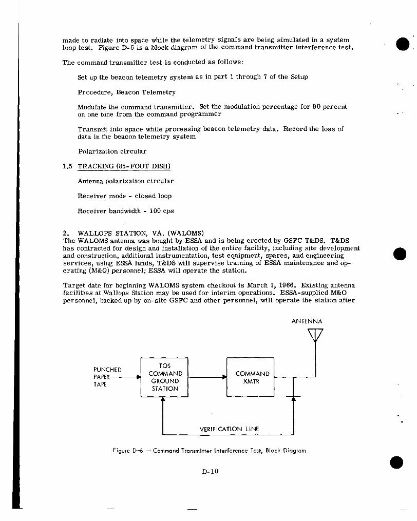
made to radiate into space while the telemetry signals a r e being simulated in a system loop test. Figure D-6 is a block diagram of the command transmitter interference test.
The command transmitter test is conducted as follows:
Set up the beacon telemetry system as in part 1 through 7 of the Setup
Procedure, Beacon Telemetry
Modulate the command transmitter. Set the modulation percentage for 90 percent on one tone from the command programmer
Transmit into space while processing beacon telemetry data. Record the loss of data in the beacon telemetry system
Polarization circular
1.5 TRACKING (85-FOOT DISH)
Antenna polarization circular
Receiver mode - closed loop
Receiver bandwidth - 100 cps
2. WALLOPS STATION, VA. (WALOMS) The WALOMS antenna was bought by ESSA and is being erected by GSFC T&DS. T&DS has contracted for design and installation of the entire facility, including site development and construction, additional instrumentation, test equipment, spares, and engineering services, using ESSA funds, T&DS will supervise training of ESSA maintenance and op- erating (M&O) personnel; ESSA will operate the station.
a Target date for beginning WALOMS system checkout is March 1, 1966. Existing antenna facilities at Wallops Station may be used for interim operations. ESSA-supplied M&O personnel, backed up by on-site GSFC and other personnel, will operate the station after
ANTENNA
I
Figure D-6 - Command Transmitter Interference Test, Block Diagram
D-10
I VERIFICATION LINE I
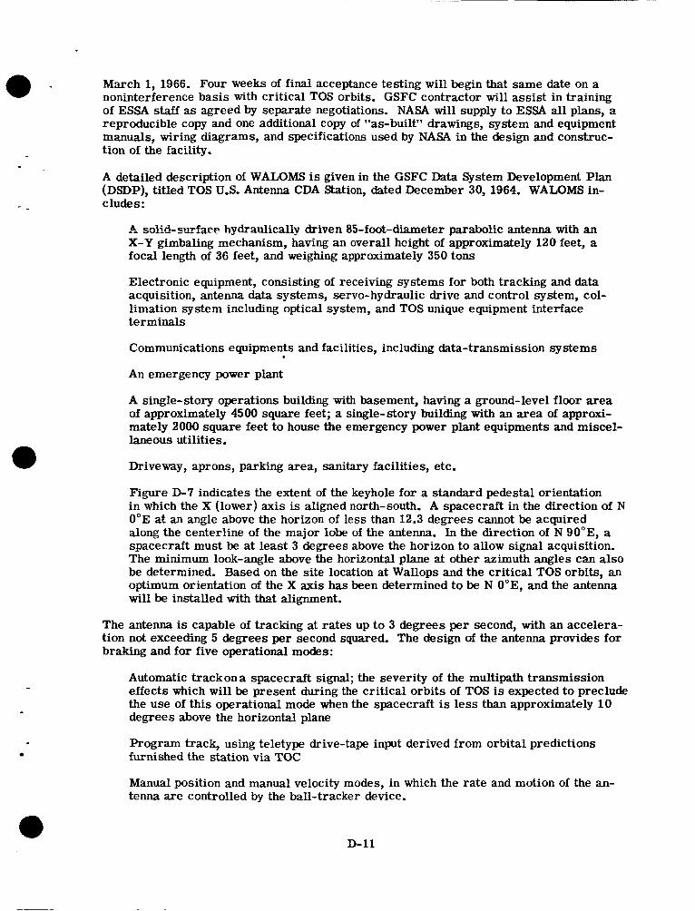
March 1, 1966. Four weeks of f inal acceptance testing will begin that same date on a noninterference basis with critical TOS orbits. GSFC contractor will assist in training of ESSA staff as agreed by separate negotiations. NASA will supply to ESSA all plans, a reproducible copy and one additional copy of "as-built" drawings, system and equipment manuals, wiring diagrams, and specifications used by NASA in the design and construc- tion of the facility.
A detailed description of WALOMS is given in the GSFC Data System Development Plan (DSDP), titled TOS U.S. Antenna CDA Station, dated December 30, 1964. WALOMS in- cludes:
A solid-surface hydraulically driven 85-foot-diameter parabolic antenna with an X-Y gimbaling mechanism, having an overall height of approximately 120 feet, a focal length of 36 feet, and weighing approximately 350 tons
Electronic equipment, consisting of receiving systems for both tracking and data acquisition, antenna data systems, servo-hydraulic drive and control system, col- limation system including optical system, and TOS unique equipment interface terminals
Communications equipments and facilities, including data-transmission systems
An emergency power plant
A single-story operations building with basement, having a ground-level floor area of approximately 4500 square feet; a single-story building with an area of approxi- mately 2000 square feet to house the emergency power plant equipments and miscel- laneous utilities.
Driveway, aprons, parking area, sanitary facilities, etc.
Figure D-7 indicates the extent of the keyhole for a standard pedestal orientation in which the X (lower) axis is aligned north-south. A spacecraft in the direction of N 0"E at an angle above the horizon of less than 12.3 degrees cannot be acquired along the centerline of the major lobe of the antenna. In the direction of N 90"E, a spacecraft must be at least 3 degrees above the horizon to allow signal acquisition. The minimum look-angle above the horizontal plane at other azimuth angles can also be determined. Based on the site location at Wallops and the critical TOS orbits, an optimum orientation of the X axis has been determined to be N O"E, and the antenna will be installed with that alignment.
The antenna is capable of tracking at rates up to 3 degrees per second, with an accelera- tion not exceeding 5 degrees per second squared. The design of the antenna provides for braking and for five operational modes:
Automatic trackona spacecraft signal; the severity of the multipath transmission effects which will be present during the critical orbits of TOS is expected to preclude the use of this operational mode when the spacecraft is less than approximately 10 degrees above the horizontal plane
Program track, using teletype drive-tape input derived from orbital predictions furnished the station via TOC
Manual position and manual velocity modes, in which the rate and motion of the an- tenna are controlled by the ball-tracker device.
D-11
NORTH
SOUTH
Figure D-7 - WALOMS Antenna Keyhole Pattern
D-12
Slaved drive, in conjunction with an acquisition aid system which supplies synchro information generated by the acquisition aid antenna equipments
Search mode, which can be superimposed over all modes of operation except the manual velocity mode
In the programming function a perforated tape containing precomputed orbital information transmitted from TOC is applied to a tape reader. Antenna position and timing commands read from the tape are used to generate, by interpolation, 1-second drive points, which are converted into analog voltages used to drive the antenna along the predicted orbital path.
The TOS unique equipment is identical to that for GILMOR.
D-13
Appendix E
I
- -
APT STATIONS
The APT ground stations acquire cloud picture data from TOS A F T satellites and re- produce them as photographic images on facsimile recorders or other suitable devices. A P T ground stations have been installed at ESSA, Navy, Army, and Air Force installa- tions as well as at many international locations and at some private agencies.
TOC will be responsible for producing and distributing APT daily alert and ephemeris prediction messages, which will include the minimum predictive data required by the ground stations to determine the antenna tracking angles to acquire the data from the spacecraft and to geographically orient the acquired pictures. The daily messages will be distributed over national and international meteorological teletypewriter circuits. The format of the daily message and the description of its use is contained in the APT User's Guide.
Detailed instructions on determining the antenna look angle for acquiring data from the spacecraft as well as procedures for geographic orientation of the pictures are also contained in the APT User ' s Guide.
Operational evaluation of the APT system by selected A P T ground stations wiH be re- quested during the checkout of the system by TEC and later during the lifetime of the satellite as deemed necessary by TOC. These later requests will be initiated by TOC through the national and international meteorological teletypewriter networks. The APT Pass Summary and Evaluation Report (Table IV-8) will be completed as requested by TOS whenever the APT TOS satellite is programmed for pictures in range of the APT station.
The APT User ' s Guide will be distributed to World Meteorological Organization members and will be available from the Government Printing Office, Washington 20025, D. C.
E- 1
Appendix F
TOS EQUIPMENT
TOC has the capability of receiving and tape recording data from both ground stations s in i l l t a rec i ly , however the display of data, on Brush recorders can only be performed one station at a time. Video data from both CDA's can be relayed simultaneously through the T05COM and processed in DAPAF.
The equipment used in TOC is:
e Ampex tape recorder
e 8 channel Brush recorder
e 2 channel Brush recorder
e 20 channel Esterline Angus recorder
e Test and calibration equipment for the above
e APT antenna and receiver
Communications facilities and responsibilities of the TOS communications (TOSCOM) system are:
a 0 304 voice switching network and control
e TTY to CDA's and TEC
e Control of wideband data lines
Figure F-1 is the layout at NESC; DAPAF is described in the NESC TOS Data Utilization Plan.
F- 1
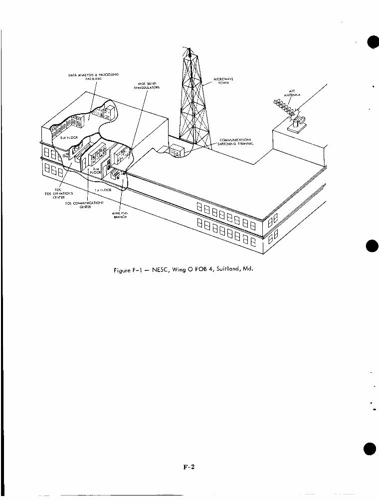
figure f -1 - NESC, Wing 0 FOB 4, Suitland, Md.
F- 2
.
Appendix G
TEC
The equipment in TEC will consist of recorders, processing and display devices which will enable the TEC crew to perform effectively during the launch and checkout phases of the TOS system.
All data signals which arrive at TEC will be recorded on magnetic tape. Most informa- tion, such as beacon data,V-scan, telemetry, etc., will be displayed in real time on chart recorders for instantaneous monitoring. Recording equipment includes:
0 Tape recorders:
Mincom or equal - Video data Ampex - Analog data
0 Brush 8-channel recorder - telemetry
0 Brush 2-channel recorder - V-scan 8 Esterline Angus 20-channel recorder - events
0 APT facsimile recorder
Other information such as the slowed-down video data and the flutter and wow signal will be recorded on the video tape recorder at ?-1/2 ips and played back at 60 ips. The AVCS video signal will be processed and displayed in the kinescope rack complex. Polaroid pictures will enable an analysis of picture quality, timing, interference, etc., by TEC personnel. The APT video signal can be obtained by the CDA stations and transmitted to TEC in the same m e r , however, normal test procedures at TEC will be to use the installed APT ground station to obtain pictures for analysis.
0
The beacon information will also be processed by an analog to digital converter and the digital signals recorded on magnetic tape. This digital tape is then fed directly into a computer for a complete tabulation of telemetry information, attitude determination and predictions, and other spacecraft criteria which are used by TEC in their evaluation of TOS spacecraft.
Additional TEC equipment includes:
0 Data processing equipment Telemetry calibrator Balanced line amplifiers Discriminators Scanner receivers Switching unit
0 Test equipment. All other equipment assigned to TEC, not of an operations use, is to be considered test equipment
0 APT ground station
G 1
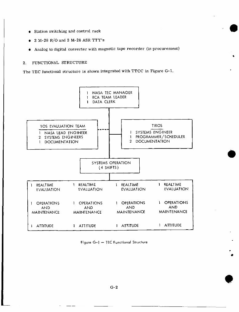
0 Station switching and control rack
0 2 M-28 R/O and 3 M-28 ASR TTY's
0 Analog to digital converter with magnetic tape recorder (in procurement)
2. FUNCTIONAL STRUCTURE
The TEC functional structure is shown integrated with TTCC in Figure G-1.
1
----- TOS EVALUATION TEAM
1 NASA LEAD ENGINEER
1 DOCUMENTATION 2 SYSTEMS ENGINEERS
1 NASA TEC MANAGER 1 RCA TEAM LEADER 1 DATA CLERK
I
T IROS
1 SYSTEMS ENGINEER
2 DOCUMENTATION 1 PROGRAMMER/ SCHEDULER
1 OPERATIONS 1 OPERATIONS 1 OPERATIONS 1 OPERATIONS AND AND AND AND
MA I N T E NAN CE MAINTENANCE MA I NT E N A N CE MA I N T E N A N CE
1 ATTITUDE 1 ATTITUDE 1 ATTITUDE 1 ATTITUDE
Figure G-l - TEC Functional Structure
G- 2
t
4. NESC COMMUNICATION FACILITIES
Appendix H
GROUND COMMUNICATIONS
1. COMMUNICATIONS LINKS
The communications links for the TO6 ground system include wideband video, alternate TTY/voice, narrowband data, and voice channels (Figure H-1).
The TOS communications will have X-136 wideband terminals to receive all data from WALOMS and GILMOR. The X-136 terminals are part of a 48-kc broadband communi- cations system for TOS. The channel assignments are as follows:
Channel A - 24 kc - Video Channel B - 4 kc - Beacon Channel C - 4 kc - Flutter and Wow Channel D - 4 kc - FSK Multiplex Channel E - 4 kc - Alternate voice/Teletype Channel F - 4 kc - Voice Channel G - 4 kc - Voice
3. GSFC SUPPORT COMMUNICATIONS FOR LAUNCH AND CHECKOUT
The NASA communications (NASCOM) global network provides ground communications support for all NASA spaceflight programs. These communications facilities, in conjunc- tion with the 304 switching unit at NESC, will be used for launch and checkout and STADAN coordination.
Communications links to all participating stations will be provided as required via NASA Communications Division's facilities (in combination with ESSA facilities).
NESC will operate the TOS Communications (TOGCOM) net.
4.1 LONGLINE SYSTEM For the operational system, 48-kc data channels from GILMOR and WALOMS will be operated by NESC. The TOS terminals at WALOMS and GILMOR will consist of one X-136 send/receive terminal and a hot spare, which can be switched onto the 48-kc wideband link connecting the TOS station and NESC if the primary terminal fails. This terminal, although full-duplex, will usually operate with WALOMS and GILMOR to send spacecraft and station events data to NESC. NESC will transmit operational instructions, programming data, and other data as necessary to WALOMS and GILMOR. GSFC will be suitably bridged to receive WALOMS and GILMOR data transmission and all transmis- sions from NESC for spacecraft and system evaluation. Offutt AFE3 will have two X-136s
f
to receive only.
4.2 NESC X-304 VOICE COMMUNICATIONS Three exterior two-way voice circuits between the 304 patching and switchboard at NESC and TEC will be used for voice communications. These circuits can be patched to any station in the TOS system through the Suitland 304 board.
H- 1
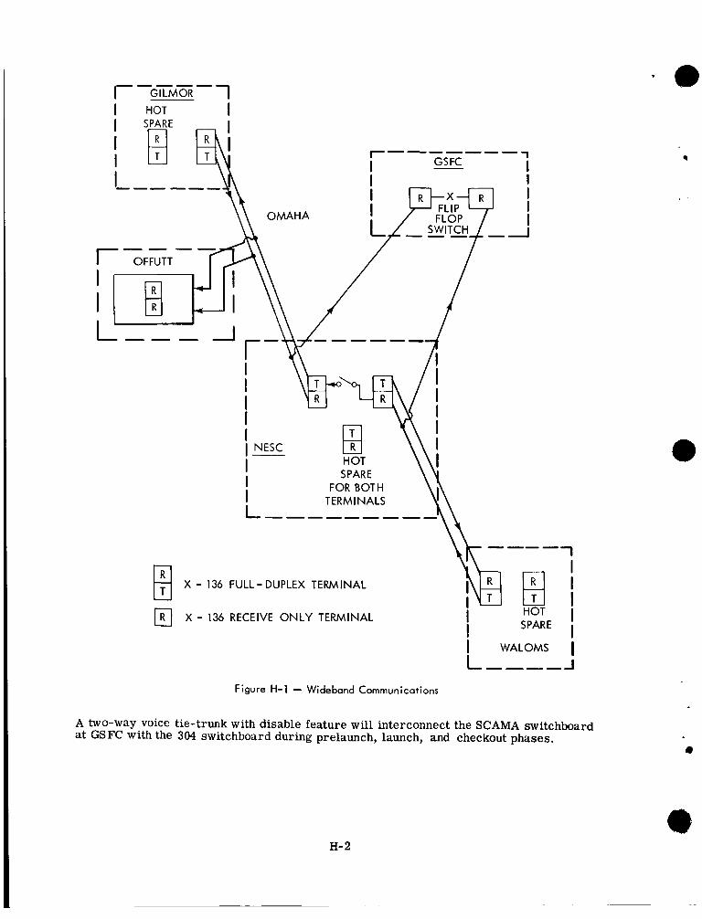
r------- 1 GS FC I I
I
I I I
I I
FLOP I OMAHA ---
q - - i - - f l \ / I / I
I I I
/
I
I I
I NESC
SPARE FOR BOTH
X - 136 FULL-DUPLEX TERMINAL
a X - 136 RECEIVE ONLY TERMINAL
1 &j-i I I I
I I I
L,---J
HOT I SPAR E
I WALOMS I
Figure H-1 - Wideband Communications
A two-way voice tie-trunk with disable feature will interconnect the S C A M switchboard at GSFC with the 304 switchboard during prelaunch, launch, and checkout phases.
H- 2
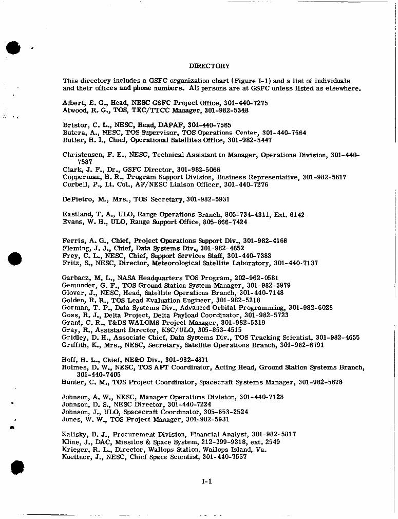
DIRECTORY
This directory includes a GSFC organization chart (Figure 1-1) and a list of individuals and their offices and phone numbers. All persons are at GSFC unless listed as elsewhere.
Albert, E. G., Head, NESC GSFC Project Office, 301-440-7275 Atwood, R, G., TOS, TEC/TTCC Manager, 301-982-5348
Bristor, C. L., NESC, Head, DAPAF, 301-440-7565
Butler, H. I., Chief, Operational Satellites Office, 301-982-5447
Christensen, F. E., m S C , Technical Assistant t o Manager, Operations Division, 301-440-
Clark, J. F., Dr., GSFC Director, 301-982-5066 Copperman, H. R., Program Support Division, Business Representative, 301-982-5817 Corbell, P., Lt. Col., AF/NESC Liaison Officer, 301-440-7276
B.;t~ra, A., SEX, TO§ !%WXT~S~?~, TOS Q ~ r ~ t , t i o ~ ~ Cl~~ter, 301-440-7564
7587
DePietro, M., Mrs., TW Secretary, 301-982-5931
Eastland, T. A., ULO, Range Operations Branch, 805-734-4311, Ext. 6142 Evans, W. H., ULO, Range Support Office, 805-866-7424
Ferris, A. G,, Chief, Project Operations Support Div., 301-982-4168 Fleming, J. J., Chief, Data Systems Div., 301-982-4652 Frey, C. L., NESC, Chief, Support Services Staff, 301-440-7383 Fritz, S,, NESC, Director, Meteorological Satellite Laboratory, 301-440-7137
Garbacz, M. L., NASA Headquarters TOS Program, 202-962-0581 Gemunder, G. F., TOS Ground Station System Manager, 301-982-5979 Glover, J., NESC, Head, Satellite Operations Branch, 301-440-7148 Golden, R. R., TOS Lead Evaluation Engineer, 301-982-5218 Gorman, T. P., Data Systems Div., Advanced Orbital Programming, 301-982-6028 GOSS, R. J., Delta Project, Delta Payload Coordinator, 301-982-5723 Grant, C. R., T&DS WALOMS Project Manager, 301-982-5319 Gray, R., Assistant Director, KSC/ULO, 305-853-4515 Gridley, D. H., Associate Chief, Data Systems Div., TOS Tracking Scientist, 301-982-4655 Griffith, K., Mrs., NESC, Secretary, Satellite Operations Branch, 301-982-6791
Hoff, H. L., Chief, NE&O Div., 301-982-4871 Holmes, D. W,, NESC, TOS APT Coordinator, Acting Head, Ground Station Systems Branch,
Hunter, C. M., TOS Project Coordinator, Spacecraft Systems Manager, 301-982-5678 301 -440-7405
Johnson, A. W,, NESC, Manager Operations Division, 301-440-7128
Johnson, J., ULO, Spacecraft Coordinator, 3 05- 853 - 2 52 4 Jones, W. W., TOS Project Manager, 301-982-5931
Kalisky, B. J., Procurement Division, Financial Analyst, 301-982-5817 Kline, J., DAC, Missiles & Space System, 212-399-9318, ext. 2549 Krieger, R. L., Director, Wallops Station, Wallops Island, Va. Kuettner, J., NESC, Chief Space Scientist, 301-440-7557
* Johnson, D. S., NESC Director, 301-440-7224
c1
I- 1
Laudrille, R. A., NESC, TOS Ground Communications, 301-440-7384 Lebanoff, L., ULO, Delta Operations Branch, 805-734-4311, Ext. 247 Logan, F. J., Tracking and Telemetry Engineer, 301-982-4935 Loewenstern, J., TOS Test Support Resident at RCA-AED, 609-448-3400, Ext. 2238
Mace, L. M., NESC, Supervisor, Analysis Soction, 301-440-7565 Mengel, J. T., T&DS, Assistant Director, GSFC, Tracing and Data Systems, 301-982-4765 Mentges, C. W., Data Systems Div., 301-982-4923 Menton, M., Project Business Representative, 301-982-5634 Moore, H. S., NESC, Acting Head, Space Systems Branch, 301-440-7546 Mosier, E. A., T&E TOS Quality Assurance Representative, 301-982-5678
Neilon, J., Deputy Assistant Director, KSC, ULO 305-853-3136 Newell, G., NASA GSFC GILMOR CDA Station Manager, 907-452-1155 Norris, T. B., NASA Headquarters Delta Program Manager, 202-962-4534
Over, J. J., TOS Technical Advisor, 301-982-5979
Parks, G. T., Data Systems Div., IBM Computer Operations, 301-982-5642 Plew, W. H., NESC, Supervisor, Photographic Section, 301-440-7548 -le, R. L., NESC, Data Systems Branch, 301-440-7544
Raynore, W. L., NESC, DAPAF, Supervisor, Electronic Services Section, 301-440-7562 Repass, G. D., Data Systems Div., 301-982-4373 Richards, J., DAC, Missiles & Space Systems, 213-399-9318, Ext. 2544 Rossi, A. D., Project Operations Support Div., Tracking and Data Systems Manager,
301- 982-6063
Schindler, W. R., Delta Project Manager, Vehicle Systems Manager, 301-982-4204 Schlimmer, G. E., ULO, Vehicle and Spacecraft Support Branch, 805-734-4311, Ext. 551 Schnapf, A., RCA-AED, Project Manager for TOS, 609-448-3400, Ext. 2774 Schwalb, A., NESC, Satellite Operations Branch, 301-440-7148 Schwartz, J., ULO, Associate Manager WTR, 805-734-4311, Ext. 551 Sheppard, D., ULO, Spacecraft and Vehicle Operations Branch, 305-853-7211 Siry, J. W., Dr., DSD, Chief, Theory & Analysis Office, 301-982-4905 Steffey, D., DAC ETR, Tes t Conductor, 305-853-2317 Stelter, L. R., Chief, NASA Communications Division, 301-982-5257 Stevens, F., ULO, Range Operations Manager, 305-494-2419
Tepper, M., Dr., NASA Headquaters, Meteorological Programs Director, 202-963-6521 Tourville, L., NESC, GILMOR CDA Station banager , 907-452-1155 Townsend, J. W., Jr., GSFC Deputy Director, 301-982-5121
Vaeth, J. S., NESC, Manager TOS Systems Engineering Division, 301-440-7395 Van Dyke, H., NESC, Wallops CDA Station Manager, 703-UA4-3411, Ext. 521
Werking, R. D., Data Systems Div., Orbit and Attitude Computation Engineer, 301-982-4674 Weston, H., ULO, ETR Delta Operations Manager, 305-853-5117 Wright, R. L., Contract Negotiator, 301-982-4201
Young, T. C., Communications Engineer, 301-982-6791
Zavos, B., NESC, TOS Data Utilization Manager, 301-440-7587 Zeman, J., ULO MCC Manager, 305-853-3319
I- 2
.I-
, -,
DISTRIBUTION LIST:
Abid, G. E., Code 263 Adams, R. H., Code 512 Army Map Service, Washington, D. C. 20315(2) Aucremanne, M. J., NASA Headquarters, Code SG
Eziixam, R. C., Code 720 Bavely, J. C., NASA Headquarters, Code TN (2) Bellamy, J., Director, National Resources Institute, University of Wyoming, Larramie, WYO. Benham, T, A., Haverford College, Haverford, Pennsylvania 19041 Berbert, J. H., Code 514 fJodin, W, J., Jr., Code 530 Bourdeau R, E., Code 400 Brown, L. E., Code 523 Brozena, A. G., Code 470 Buckley, E. E., NASA Headquarters, Code T Butler, H. I., Code 480 Byrd, V. H., Code 534
Carbaugh, J. P., Code 572 (6) Carter, E. J., Code 505 Chrisman, H., Head, Operational Research Branch, Naval Research Laboratory, Washing-
CINCNORAD, ENT Air Froce Base, Colorado Springs, Colorado 80912 (5) NITA-S, NOOP-
Clark, J, F., Dr., Code 100 Coates, R. J., Dr., Code 520 Collins, R. W., Code 535 Commanding Officer, Naval Research Laboratory, Chesapeake Bay Annex, Attn.: Code
Cook, J, W., Code 505 Cortwright, E. M., NASA Headquarters, Code SD Covington, 0. M., Code 501 Crane, J., NASA STADAN Facility, P. 0. Box 727, Barstow, Calif. (MOJAVE) Creighton, V. J., ARM Development Office, AFMTC, Patrick AFB, Florida 32925 Creveling, C. J., Code 561
ton, D. C., 20390
S, NOCC-SC-(2), "T
5330-CBA, Chesapeake Beach, Maryland 20732
Davis, Col. J., Eglin AFB, Fla. Dennis, G,, ROSMAN Director, Naval Research Laboratory, Code 5332, Washington, D. C., 20390 Director, U. S. Army Electronics Lab., Hq., U. S. Army Electronics Cmd., Att.:
Drummond, R. R., Code 731 Dunst, J. W., Code 264
AMSEL-RD-SM (Evans Area), Mr. Steelman, Fort Monmouth, New Jersey 07703
Enders, J. H., NASA Headquarters, Code FWO
Ferris, A. G., Code 510 Fielder, D., NASA Manned Spacecraft Center, Houston, Texas 77058 First Aerospace Sqdn., ENT Air Force Base, Colorado Springs, Colorado 80912 (5) Fitzgerald, R. T., Code 531 Fleming, J. J., Code 540
Garbarini, R. F., NASA Headquarters, Code SE (3) Gemunder, G. F., Code 480
1-3
Goddard News Office, Code 202 Gorman, T. P., Code 565 GOSS, R. J., Code 470 Gray, R. H., NASA, Unmanned Launch Operations, ETR, Post Office Box 186, Port
Gridley, D. H., Code 540 GSFC Library, Code 252 (3)
Canaveral, Florida 32920
Habib, E. J., Code 560 Healy, W. J., Code 511 Heller, N. R., Code 506 (5) Helms, Mr., Jet Propulsion Laboratory, Bldg. 190, Room 118, 4800 Oak Grove Drive,
Hess, W. N., Dr., Code 640 Hicks, R. L., Code 508 (5) Hightower, L. E., Code 530 Hoff, H. L., Code 530 Hooker, R. W., NASA Senior Scientific Representative, c/o Department of Supply, 339
Hopkins, H. G., Dr., Director, RRS, DSIR, Ditton Park Slough Bucks, England (4) Humphrey, F. S., Code 572
Jackson, J. C., Code 550 Jones, W. W., Code 480 (25)
Kiebler, J. W., Code 510 Kohout, J. M., Code 510 Kreiger, R. L., Director, Wallops Station, Wallops Island, Va.
Lagow, H. E., Code 300 Logan, F. J., Code 531
Martin, J.B., Code 530 Maskaleris, C. L,, GSFC Representative, Weapons Research Establishment, Box 1424H
Mathews, C. W., NASA Manned Spacecraft Center, Houston, Texas 77058 Matthews, N. W., Code 710 (5) Mazur, D. G., Code 700 McCaffery, R. J., Code 506 McGee, L., QUITOE Mengel, J. T., Code 500 (3) Mentges, C. W., Code 541 Meredith, L. H., Code 610
NASA Communications Center, c/o Division Engineer, Telegrams PMG Department, 42
NASA Sub-switching Center, Room 529, Electra House, Victoria Embankment, London
NASA Honolulu Sub-switching Center, 1130 Alakea Street, Honolulu, Hawaii 96313 National Environmental Satellite Center, ESSA, Washington, D. C. 20025 (100) NAVSPASUR, Naval Space Surveillance System, Dahlgren, Virginia 22449, Attn.: Senior
NETCON, Code 512 (10)
Operations Support Office, Code 530 OPSCON, Code 512 (20)
Pasadena, California 91103
Swanson Street, Melbourne, Australia
GPO, Adelaide, South Australia
Franklin Street, Adelaide, South Australia, Attn: Mr. E. E. Quin (2)
W.C. 2, England, Attn.: Mr. Dallas Tuning (2)
Operations Officer (5)
t
I- 4
. i
.- -
t
6
L
Peterson, C. M., Chief of Communications, Smithsonian Astrophysical Observatory, 60
PIO, Code 202 (3) PMRF'HAW Area, Navy 990, c/o FPO, San Francisco, California 96641, Attn.: HO 3 Poland, W. B., Jr., Code 563 (3) Purcell, J. P., Code 532
d Garden Street, Cambridge, Mass. 02133 (28)
RCA-AED, Hightstown, N. J., Attn.: Mr. A. Schnapf Rettie, R. S., Dr., National Research Council, Richardson, B., Code 541 Ritch, R. E., Code 511 (3) Rogers, R. J., Code 576 Rogers, W. B.: Code 572 Rosenberg, A. C., Code 564 (6) Rossi, A. D., Code 513 (5)
Canada (2)
Schindler, W. R., Code 470 Schroeder, C. A., Code 502 Schwartz, J., Unmanned Launch Operations, WTR, Post Office Box 425, Lompoc, California
Security Officer, Code 236 Shapiro, A., Code 543 Sheppard, D., Unmanned Launch Operations, ETR Post Office Box 186, Port Canaveral,
Florida 32920 (5) Simas, V. R., Code 523 Siry, J. W., Dr., Code 547 (3) Spacetrack R&D Facility, Lawrence G. Hanscom Field, Bedford, Mass.01731, Attn.: Senior
Duty Controller (2) Sparks, R., Jet Propulsion Laboratory, 4800 Oak Grove Drive, Pasadena, California 91103 Stelter, L. R., Code 570 (2) Stewart, D. J., Code 547 (2) Stockwell, E. J., NASA Headquarters, Code TN Stotler, H. J., Code 546 Stout, C. M., Code 560 stroud, W. G., Code 110 Surgen, H. R., Code 236
93438 (5)
TEC, Bldg. 14, Rm. W 210, Code 481 (12) Tepper, M., Dr., NASA Headquarters, Code SAD TOS Library, Code 480 (3) Townsend, J. W., Jr., Dr., TEC (5), Code 100 Turnbull, H. A., Code 530
Vaccaro, M. J., Dr., Code 200 Varson, W. P., Code 506
Wasielewski, E. W., Code 100 Werking, R. D., Code 547 White, W. A., Code 614 Wiley, T. N., Code 571 Wright, R. L., Code 247
Young, T. C., Code 570
Zavos, B., NESC Zeman, J., ULO/KSC
I- 5
L
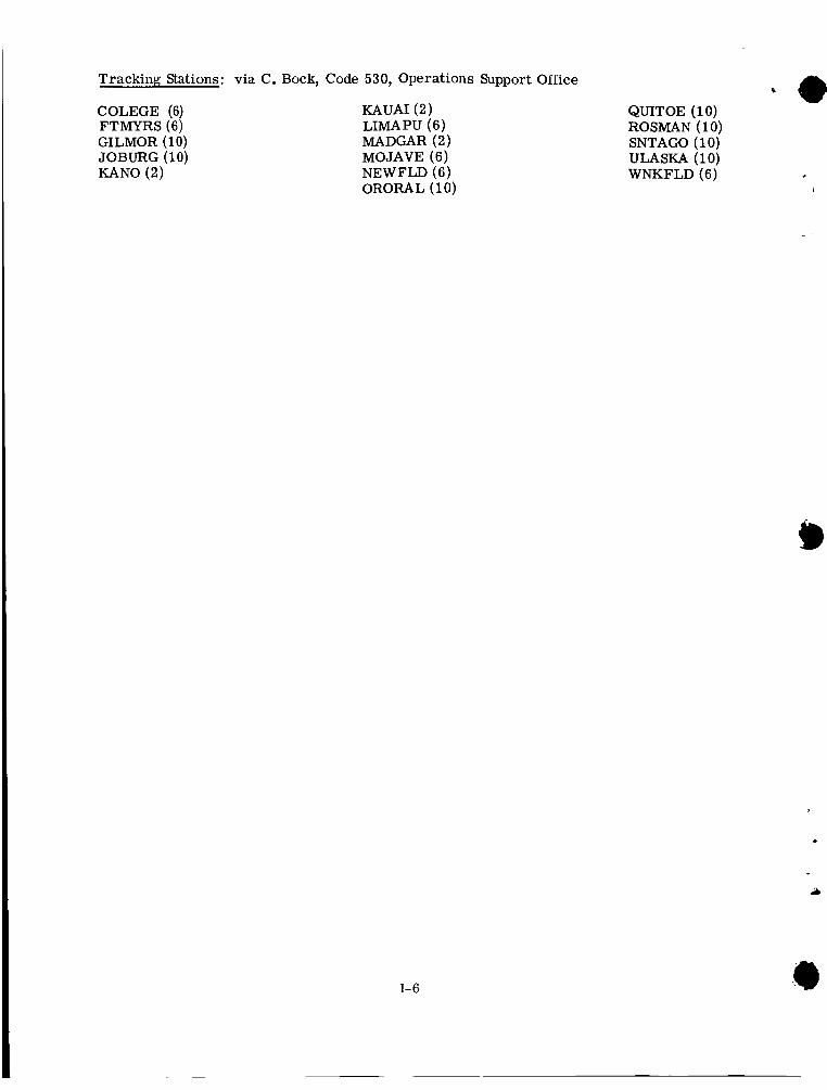
Tracking Stations: via C. Bock, Code 530, Operations Support Office
COLEGE (6) FTMYRS(6) GILMOR (1 0) JOBURG (1 0) KANO (2)
KAUAI (2) LIMAPU (6) MADGAR (2) MOJAVE (6) NEWFLD (6) ORORAL (10)
QUITOE (10) ROSMAN (10) SNTAGO (1 0)
WNKFLD (6) ULASKA (10)
i
.
I- 6