Embed Size (px)
Citation preview
Mission-critical coMMunications networks for Power utilitiesNetwork traNsformatioN with iP/mPLs for syNchroPhasor aPPLicatioNaPPLicatioN Note
abstractMomentous changes have occurred in how power utilities operate and how they deliver electricity to customers. Depending on the market, the changes have been driven by various needs: from simply making the power grid more reliable (avoiding blackouts), to coping better with the challenges of renewable energy and electric cars, to improving the quality of power (eliminating voltage surges and brownouts). Technological initiatives such as substation automation are pivotal to ensure that utilities’ power grids are ready for the future.
One principal component of substation automation is installation of a synchrophasor application, which samples current, voltage and other parameters, then makes the data available for real-time and offline analysis by various applications. However, installation of a synchrophasor application requires a robust communications network for delivery of such mission-critical data.
Rising to this challenge, Alcatel-Lucent delivers a converged IP/MPLS-based communications network for power utilities using next-generation products and advanced management systems that can meet such stringent requirements. This document analyzes the network considerations and requirements when deploying a synchrophasor application and presents a blueprint design to show how an IP/MPLS-based network can enable successful deployment.
table of contents
introduction / 1
synchrophasor applications / 1
the alcatel-Lucent iP/mPLs Network / 2
advantages / 2
many VPNs, one network / 3
key Network considerations for a synchrophasor application / 4
Understand the traffic flow / 4
redundancy protection / 6
multiservice backhaul / 7
a Blueprint Network Design for a synchrophasor application / 8
Phasor data collection topology / 8
Physical network topology / 8
multicast tree delivery mechanism / 10
a hierarchical VPLs design / 11
conclusion / 13
acronyms / 14
Mission-critical Communications Networks for Power UtilitiesAlcAtel-lucent ApplicAtion note
1
introductionInvestments in power utility projects have been fueled by initiatives dedicated to substation automation and smart grids. While most of the media attention has been on the effects of smart grids on consumers, substation automation is equally important. Its key component is a synchrophasor application to sample current, voltage and other parameters, then make the data available for real-time and offline analysis by various applications.
Due to the high sampling rate, synchrophasor applications are typically more bandwidth-intensive than supervisory control and data acquisition (SCADA) applications; this makes a robust communications network vital. In response, many power utilities have started transforming their SONET/SDH/PDH/TDM-based networks to converged IP/MPLS networks to carry monitoring, control and status data and also handle legacy traffic.
This converged network enables a power utility to maximize the cost-effectiveness and productivity of its network without jeopardizing reliability and also to deploy new devices and applications that can improve operational and workflow efficiency. A highly available IP/MPLS network is ideally suited to support both mission-critical operations and all other corporate communications requirements.
In addition, an Alcatel-Lucent IP/MPLS network meets these requirements and also allows power utilities to improve their efficiency by automating and simplifying operations management for communications services, thereby reducing the barrier to introducing IP/MPLS-based technologies and services.
synchroPhasor aPPlicationsA synchrophasor application, an indispensable part of substation automation, is a real-time application vital for reliable and stable operations of the bulk power systems. It can also play a key role in optimizing energy transit in interconnected bulk power systems. It does so by providing reliable and immediate feedback to the control center through probes called phasor measurement units (PMUs) installed at the substation. The PMUs stream real-time situational data over a robust WAN to a data collector called a phasor data concentrator (PDC).
The information in the data stream sent from each PMU includes the time of measurement, the amplitude and phase of the phasor, the frequency and the rate of change of frequency.
According to a NERC report, power utilities, armed with such precise, time-synchronized, power-grid-wide data, can improve grid stability and reliability for both real-time operations and offline planning applications as listed below1.
Real-time operations applications
• Wide-areasituationalawareness
• Frequencystabilitymonitoringandtrending
• Poweroscillationmonitoring
• Voltagemonitoringandtrending
1 NERC, Real-Time Application of Synchrophasors for Improving Reliability, October 2010, http://www.nerc.com/docs/oc/rapirtf/RAPIR%20final%20101710.pdf
Mission-critical Communications Networks for Power UtilitiesAlcAtel-lucent ApplicAtion note
2
• Alarmingandsettingsystemoperatinglimits,eventdetectionandavoidance
• Resourceintegration
• Stateestimation
• Dynamiclineratingsandcongestionmanagement
• Outagerestoration
• Operationsplanning
Planning and off-line applications
• Baseliningpowersystemperformance
• Eventanalysis
• Staticsystemmodelcalibrationandvalidation
• Dynamicsystemmodelcalibrationandvalidation
• Powerplantmodelvalidation
• Loadcharacterization
• Specialprotectionschemesandislanding
• Primaryfrequency(governing)response
Successful deployment of a synchrophasor application is crucial to an efficient and robust grid that delivers an unceasing flow of electricity to users without faults or even brief interruption.
the alcatel-lucent iP/MPls networkadvantagesMany power utilities have started to consider deploying, or have already deployed, next-generation networks to support all their communications needs. However, not all next-generation solutions are appropriate for power utilities. To simultaneously support all mission-critical and non-mission-critical traffic of a power utility, an IP/MPLS-based communications network is needed.
Non-MPLS-based IP networks have grown significantly in recent years, but they often lack the necessary traffic management capability to support traffic that requires strict quality of service (QoS) for mission-critical operations. They also lack the flexibility to optimize the use of network resources and the capability to react to network events fast enough to guarantee end-to-end QoS per application.
ByusinganAlcatel-LucentIP/MPLS,thepowerutilitygetsthebestofbothworlds— an IP network that has the robustness and predictability of a circuit-based network along with high capacity and support for packet-based traffic with high QoS. An IP/MPLS network enables the deployment of new IP/Ethernet applications and also supports existing TDM-based applications, allowing the power utility to improve services for both internal and external users. A power utility can continue to support existing TDM services and flexibly choose when to migrate them to IP.
With an IP/MPLS network, the power utility has a network with the following features:
• HighscalabilityandrobustnesswithfullredundancyandrapidrecoverymechanismsuchasMPLSFastReroute(FRR)
• AsolutionthataddressesawiderangeofQoSandservicelevelagreement(SLA)requirements, from circuit emulation to best-effort Internet surfing
Mission-critical Communications Networks for Power UtilitiesAlcAtel-lucent ApplicAtion note
3
• Optimizedbandwidthusageofalllinksandavoidanceofcommonmodesthroughtraffic engineering
• Anextensiveoperations,administrationandmaintenance(OAM)suiteforperformancemonitoring, troubleshooting and maintenance at all protocol layers
• Advancednetworkandservicemanagementtosimplifyoperations
Each application run on the network has its unique requirements for bandwidth, QoS and availability. An IP/MPLS network enables the power utility to set service parameters for each service and traffic type according to operational requirements. This includes multiple types of voice, video and data traffic. The network can also support low jitter and delay to handle all traffic types effectively and reliably in real time. In addition, the Alcatel-Lucent IP/MPLS network supports advanced capabilities, including non-stop routing,non-stopservicesandFRR,tomaintainhighnetworkresiliency.
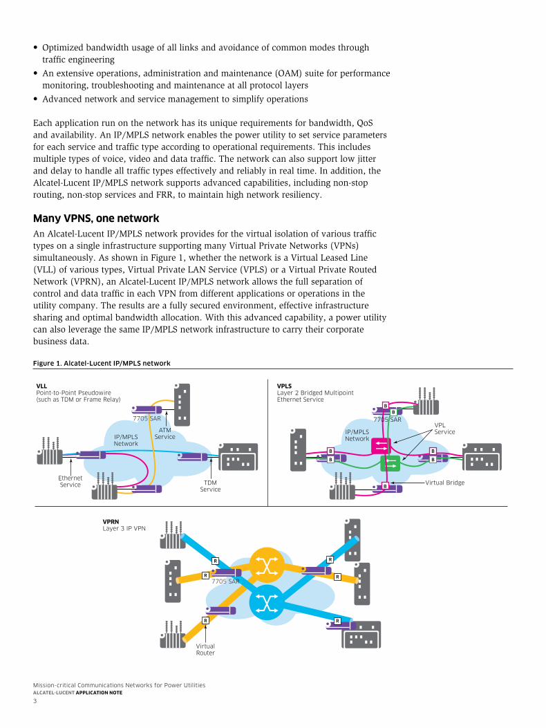
Many VPns, one networkAn Alcatel-Lucent IP/MPLS network provides for the virtual isolation of various traffic typesonasingleinfrastructuresupportingmanyVirtualPrivateNetworks(VPNs)simultaneously.AsshowninFigure1,whetherthenetworkisaVirtualLeasedLine(VLL)ofvarioustypes,VirtualPrivateLANService(VPLS)oraVirtualPrivateRoutedNetwork(VPRN),anAlcatel-LucentIP/MPLSnetworkallowsthefullseparationofcontrolanddatatrafficineachVPNfromdifferentapplicationsoroperationsintheutility company. The results are a fully secured environment, effective infrastructure sharing and optimal bandwidth allocation. With this advanced capability, a power utility can also leverage the same IP/MPLS network infrastructure to carry their corporate business data.
Figure 1. Alcatel-Lucent IP/MPLS network
VPLService
Virtual Bridge
VPLSLayer 2 Bridged Multipoint Ethernet Service
IP/MPLSNetwork
B B
B B
ATMService
VLLPoint-to-Point Pseudowire(such as TDM or Frame Relay)
IP/MPLSNetwork
TDMService
EthernetService
VPRNLayer 3 IP VPN
VirtualRouter
R R
R
R
R
7705 SAR
7705 SAR
R
BB
B
7705 SAR
Mission-critical Communications Networks for Power UtilitiesAlcAtel-lucent ApplicAtion note
4
alcatel-lucent solution components overviewThe Alcatel-Lucent IP/MPLS implementation provides a service-oriented approach that focuses on service scalability and quality as well as per-service OAM. With a service-aware infrastructure, the power utility has the ability to tailor services such as mission-critical applications so that it has the guaranteed bandwidth to meet peak requirements. The Alcatel-Lucent service routers support IP routing and switching, which enables the power utility to support real-time Layer 2 and Layer 3 applications.
The Alcatel-Lucent converged IP/MPLS network leverages multiple state-of-the-art technologies. The network extends IP/MPLS capabilities from the core to access and can include the following main components:
• Alcatel-Lucent7750ServiceRouter(SR)
• Alcatel-Lucent7705ServiceAggregationRouter(SAR)
• Alcatel-Lucent7450EthernetServicesSwitch(ESS)
• Alcatel-Lucent7210ServiceAccessSwitch(SAS)
• Alcatel-Lucent9500MicrowavePacketRadio(MPR)providingpacketmicrowave link connecting MPLS nodes
• Alcatel-Lucent1830PhotonicServiceSwitch(PSS)asopticallayerunderlyingthe IP/MPLS network
• Alcatel-Lucent5620ServiceAwareManager(SAM)forserviceandnetworkmanagement
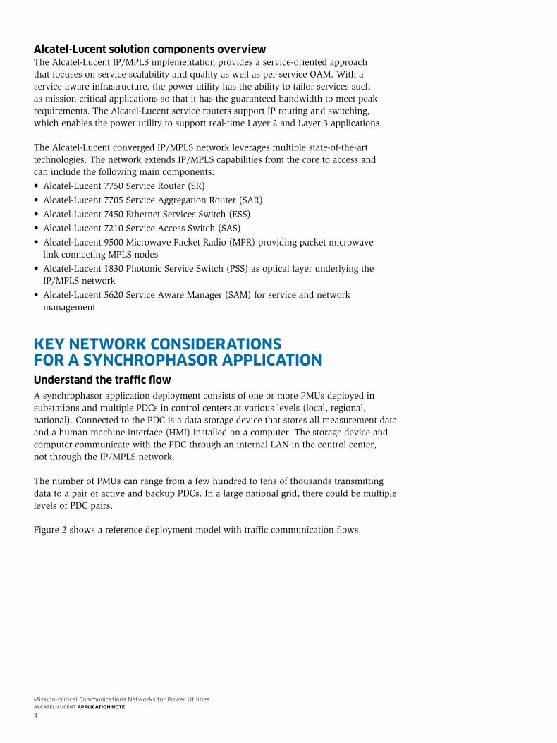
key network considerations for a synchroPhasor aPPlicationunderstand the traffic flowA synchrophasor application deployment consists of one or more PMUs deployed in substations and multiple PDCs in control centers at various levels (local, regional, national). Connected to the PDC is a data storage device that stores all measurement data and a human-machine interface (HMI) installed on a computer. The storage device and computer communicate with the PDC through an internal LAN in the control center, not through the IP/MPLS network.
The number of PMUs can range from a few hundred to tens of thousands transmitting data to a pair of active and backup PDCs. In a large national grid, there could be multiple levels of PDC pairs.
Figure2showsareferencedeploymentmodelwithtrafficcommunicationflows.
Mission-critical Communications Networks for Power UtilitiesAlcAtel-lucent ApplicAtion note
5
A few observations can be made about the reference deployment model.
Traffic flow patternEach individual PMU continually streams measurement data to a number of PDCs located in control centers at different levels for monitoring and analysis performed by different teams.Fordataredundancyprotection,itisalsocommontofindapairofPDCsateachlevel, with each PMU streaming two flows of data packets, one for each of the PDCs. Due to the high number of PMUs, which can range from a few hundred to tens of thousands, thisrepresentsacorrespondinglyhighnumberofmulticastflows—fromhundredstopotentially tens of thousands. Each multicast flow requires a separate multicast channel, whichhasitsownmulticasttree.Foreachchannel,thereareahandfuloflisteners(PDCsat various levels). The multicast trees are static once the application is up and running. This is the opposite ofatypicalcarrierIPTVapplication,wherethemulticasttreeswithuptotensofthousandsofTVviewersareestablishingandtearingdownbranchesdynamicallyasviewers change channels.
Geographic sparsity of listeners The handful of PDCs are typically located in the aggregation location of the network. ThisistheoppositeofanIPTVmulticastnetwork,inwhichthelisteners,TVviewers, are situated everywhere across various access domains.
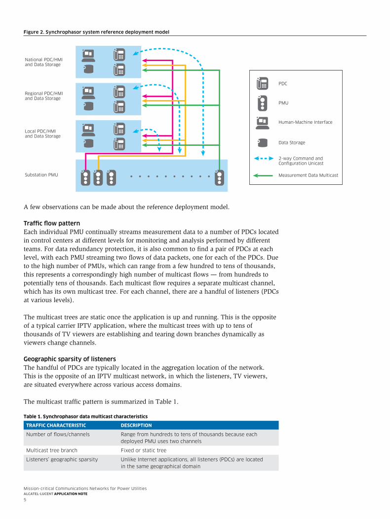
The multicast traffic pattern is summarized in Table 1.
table 1. synchrophasor data multicast characteristics
traffic characteristic descriPtion
Number of flows/channels range from hundreds to tens of thousands because each deployed PmU uses two channels
multicast tree branch fixed or static tree
Listeners’ geographic sparsity Unlike internet applications, all listeners (PDcs) are located in the same geographical domain
Figure 2. Synchrophasor system reference deployment model
National PDC/HMI and Data Storage
Regional PDC/HMI and Data Storage
Local PDC/HMI and Data Storage
Substation PMU
PMU
PDC
Data Storage
Human-Machine Interface
2-way Command and Configuration Unicast
Measurement Data Multicast
Mission-critical Communications Networks for Power UtilitiesAlcAtel-lucent ApplicAtion note
6
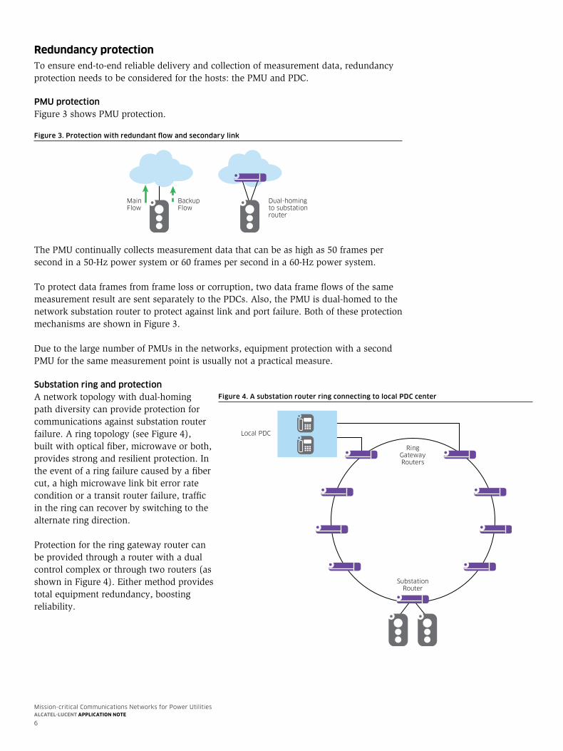
redundancy protectionTo ensure end-to-end reliable delivery and collection of measurement data, redundancy protection needs to be considered for the hosts: the PMU and PDC.
PMU protectionFigure3showsPMUprotection.
Figure 3. Protection with redundant flow and secondary link
Main Flow
BackupFlow
Dual-homingto substationrouter
ThePMUcontinuallycollectsmeasurementdatathatcanbeashighas50framespersecondina50-Hzpowersystemor60framespersecondina60-Hzpowersystem.
To protect data frames from frame loss or corruption, two data frame flows of the same measurement result are sent separately to the PDCs. Also, the PMU is dual-homed to the networksubstationroutertoprotectagainstlinkandportfailure.BothoftheseprotectionmechanismsareshowninFigure3.
Due to the large number of PMUs in the networks, equipment protection with a second PMU for the same measurement point is usually not a practical measure.
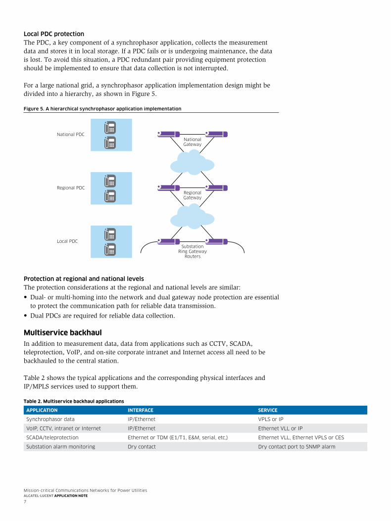
Substation ring and protectionA network topology with dual-homing path diversity can provide protection for communications against substation router failure.Aringtopology(seeFigure4),built with optical fiber, microwave or both, provides strong and resilient protection. In the event of a ring failure caused by a fiber cut, a high microwave link bit error rate condition or a transit router failure, traffic in the ring can recover by switching to the alternate ring direction.
Protection for the ring gateway router can be provided through a router with a dual control complex or through two routers (as showninFigure4).Eithermethodprovidestotal equipment redundancy, boosting reliability.
Figure 4. A substation router ring connecting to local PDC center
RingGatewayRouters
Local PDC
SubstationRouter
Mission-critical Communications Networks for Power UtilitiesAlcAtel-lucent ApplicAtion note
7
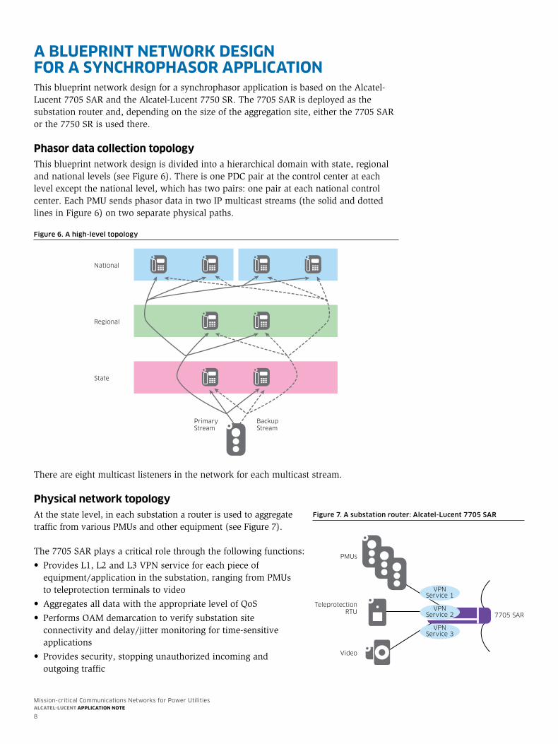
Local PDC protectionThe PDC, a key component of a synchrophasor application, collects the measurement data and stores it in local storage. If a PDC fails or is undergoing maintenance, the data is lost. To avoid this situation, a PDC redundant pair providing equipment protection should be implemented to ensure that data collection is not interrupted.
Foralargenationalgrid,asynchrophasorapplicationimplementationdesignmightbedividedintoahierarchy,asshowninFigure5.
Figure 5. A hierarchical synchrophasor application implementation
NationalGateway
RegionalGateway
SubstationRing Gateway
Routers
National PDC
Regional PDC
Local PDC
Protection at regional and national levelsThe protection considerations at the regional and national levels are similar:
• Dual-ormulti-homingintothenetworkanddualgatewaynodeprotectionareessentialto protect the communication path for reliable data transmission.
• DualPDCsarerequiredforreliabledatacollection.
Multiservice backhaulInadditiontomeasurementdata,datafromapplicationssuchasCCTV,SCADA,teleprotection,VoIP,andon-sitecorporateintranetandInternetaccessallneedtobebackhauled to the central station.
Table 2 shows the typical applications and the corresponding physical interfaces and IP/MPLS services used to support them. table 2. Multiservice backhaul applications
aPPlication interface serVice
synchrophasor data iP/ethernet VPLs or iP
VoiP, cctV, intranet or internet iP/ethernet ethernet VLL or iP
scaDa/teleprotection ethernet or tDm (e1/t1, e&m, serial, etc,) ethernet VLL, ethernet VPLs or ces
substation alarm monitoring Dry contact Dry contact port to sNmP alarm
Mission-critical Communications Networks for Power UtilitiesAlcAtel-lucent ApplicAtion note
8
a bluePrint network design for a synchroPhasor aPPlicationThis blueprint network design for a synchrophasor application is based on the Alcatel-Lucent7705SARandtheAlcatel-Lucent7750SR.The7705SARisdeployedasthesubstationrouterand,dependingonthesizeoftheaggregationsite,eitherthe7705SARorthe7750SRisusedthere.
Phasor data collection topologyThis blueprint network design is divided into a hierarchical domain with state, regional andnationallevels(seeFigure6).ThereisonePDCpairatthecontrolcenterateachlevel except the national level, which has two pairs: one pair at each national control center. Each PMU sends phasor data in two IP multicast streams (the solid and dotted linesinFigure6)ontwoseparatephysicalpaths.
Figure 6. A high-level topology
National
Regional
State
PrimaryStream
BackupStream
There are eight multicast listeners in the network for each multicast stream.
Physical network topologyAt the state level, in each substation a router is used to aggregate trafficfromvariousPMUsandotherequipment(seeFigure7).
The7705SARplaysacriticalrolethroughthefollowingfunctions:
• ProvidesL1,L2andL3VPNserviceforeachpieceofequipment/application in the substation, ranging from PMUs to teleprotection terminals to video
• AggregatesalldatawiththeappropriatelevelofQoS
• PerformsOAMdemarcationtoverifysubstationsite connectivity and delay/jitter monitoring for time-sensitive applications
• Providessecurity,stoppingunauthorizedincomingand outgoing traffic
Figure 7. A substation router: Alcatel-Lucent 7705 SAR
PMUs
TeleprotectionRTU
Video
7705 SAR
VPNService 1
VPNService 2
VPNService 3
Mission-critical Communications Networks for Power UtilitiesAlcAtel-lucent ApplicAtion note
9
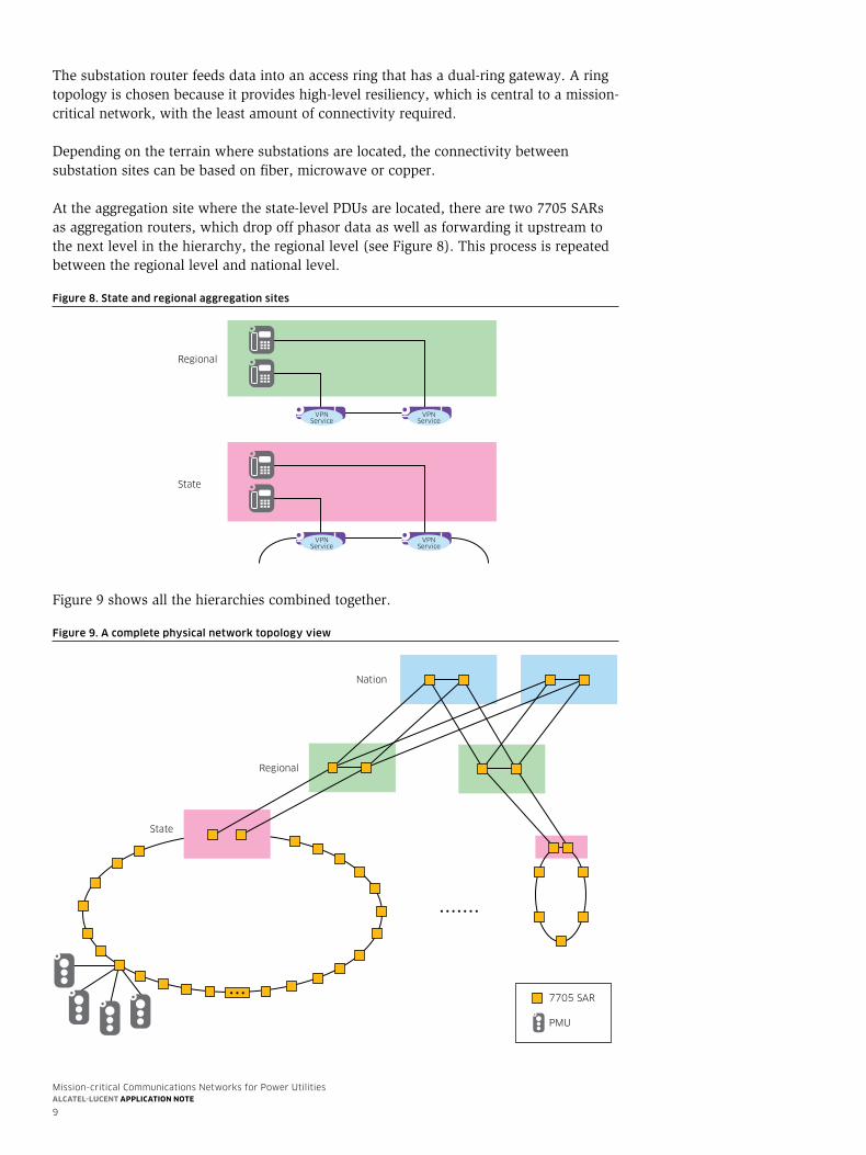
The substation router feeds data into an access ring that has a dual-ring gateway. A ring topology is chosen because it provides high-level resiliency, which is central to a mission-critical network, with the least amount of connectivity required.
Depending on the terrain where substations are located, the connectivity between substation sites can be based on fiber, microwave or copper.
Attheaggregationsitewherethestate-levelPDUsarelocated,therearetwo7705SARsas aggregation routers, which drop off phasor data as well as forwarding it upstream to thenextlevelinthehierarchy,theregionallevel(seeFigure8).Thisprocessisrepeatedbetween the regional level and national level.
Figure 8. State and regional aggregation sites
State
Regional
VPNService
VPNService
VPNService
VPNService
Figure9showsallthehierarchiescombinedtogether.
Figure 9. A complete physical network topology view
Nation
Regional
State
.......
7705 SAR
PMU
...
Mission-critical Communications Networks for Power UtilitiesAlcAtel-lucent ApplicAtion note
10
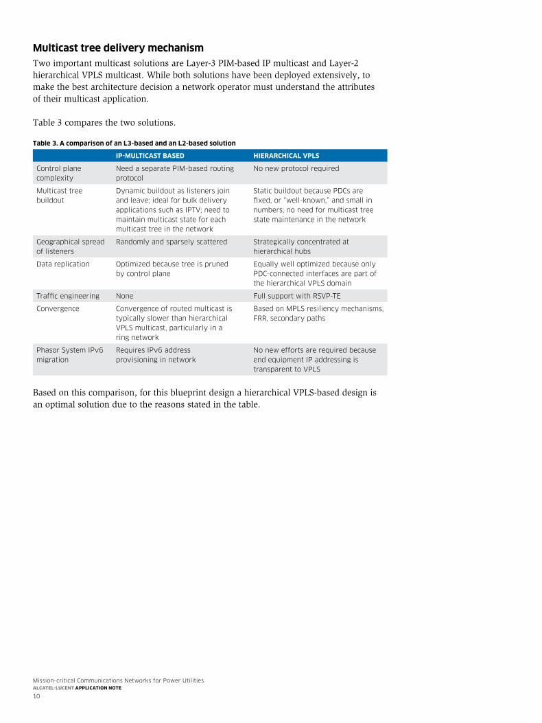
Multicast tree delivery mechanismTwo important multicast solutions are Layer-3 PIM-based IP multicast and Layer-2 hierarchicalVPLSmulticast.Whilebothsolutionshavebeendeployedextensively,tomake the best architecture decision a network operator must understand the attributes of their multicast application.
Table 3 compares the two solutions.
table 3. a comparison of an l3-based and an l2-based solution
iP-Multicast based hierarchical VPls
control plane complexity
Need a separate Pim-based routing protocol
No new protocol required
multicast tree buildout
Dynamic buildout as listeners join and leave; ideal for bulk delivery applications such as iPtV; need to maintain multicast state for each multicast tree in the network
static buildout because PDcs are fixed, or “well-known,” and small in numbers; no need for multicast tree state maintenance in the network
Geographical spread of listeners
randomly and sparsely scattered strategically concentrated at hierarchical hubs
Data replication optimized because tree is pruned by control plane
equally well optimized because only PDc-connected interfaces are part of the hierarchical VPLs domain
traffic engineering None full support with rsVP-te
convergence convergence of routed multicast is typically slower than hierarchical VPLs multicast, particularly in a ring network
Based on mPLs resiliency mechanisms, frr, secondary paths
Phasor system iPv6 migration
requires iPv6 address provisioning in network
No new efforts are required because end equipment iP addressing is transparent to VPLs
Basedonthiscomparison,forthisblueprintdesignahierarchicalVPLS-baseddesignisan optimal solution due to the reasons stated in the table.
Mission-critical Communications Networks for Power UtilitiesAlcAtel-lucent ApplicAtion note
11
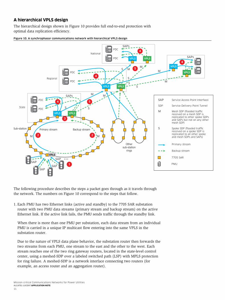
a hierarchical VPls designThehierarchicaldesignshowninFigure10providesfullend-to-endprotectionwithoptimal data replication efficiency.
The following procedure describes the steps a packet goes through as it travels through thenetwork.ThenumbersonFigure10correspondtothestepsthatfollow.
1.EachPMUhastwoEthernetlinks(activeandstandby)tothe7705SARsubstationrouter with two PMU data streams (primary stream and backup stream) on the active Ethernet link. If the active link fails, the PMU sends traffic through the standby link.
When there is more than one PMU per substation, each data stream from an individual PMUiscarriedinauniqueIPmulticastflowenteringintothesameVPLSinthesubstation router.
DuetothenatureofVPLSdataplanebehavior,thesubstationrouterthenforwardsthetwo streams from each PMU, one stream to the east and the other to the west. Each stream reaches one of the two ring gateway routers, located in the state-level control center, using a meshed-SDP over a labeled switched path (LSP) with MPLS protection for ring failure. A meshed-SDP is a network interface connecting two routers (for example, an access router and an aggregation router).
Figure 10. A synchrophasor communications network with hierarchical VPLS design
VPLS VPLS
...
National
Regional
State
PDC
Primary streamSub-station
Othersub-station
rings
Backup stream
Primary stream
Backup stream
SAP
SAPSAP
SAP
1
2
4 5
5
4
3
2
VPLS
M
M
MM
M
M
MSAPs
SAPs
SAPs
S
S
S
SS
S
M
PDC
PDC
PDC
VPLS VPLS
PDC
PDC VPLS VPLS
VPLS
VPLS
4
4
7705 SAR
PMU
SAP Service Access Point Interfacei
SDP Service Delivery Point Tunnel
M Mesh SDP ( flooded traffic received on a mesh SDP is replicated to other spoke SDPs and SAPs but not on any other mesh SDP)
S Spoke SDP (flooded traffic received on a spoke SDP is replicated to all other spoke and mesh SDPs and SAPs)
Mission-critical Communications Networks for Power UtilitiesAlcAtel-lucent ApplicAtion note
12
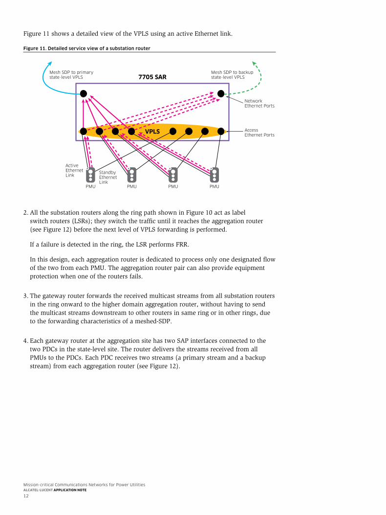
Figure11showsadetailedviewoftheVPLSusinganactiveEthernetlink.
Figure 11. Detailed service view of a substation router
PMU
ActiveEthernetLink
StandbyEthernetLink
PMU
VPLS
7705 SAR
PMU PMU
Access Ethernet Ports
NetworkEthernet Ports
Mesh SDP to primary state-level VPLS
Mesh SDP to backup state-level VPLS
2.AllthesubstationroutersalongtheringpathshowninFigure10actaslabel switch routers (LSRs); they switch the traffic until it reaches the aggregation router (seeFigure12)beforethenextlevelofVPLSforwardingisperformed.
Ifafailureisdetectedinthering,theLSRperformsFRR.
In this design, each aggregation router is dedicated to process only one designated flow of the two from each PMU. The aggregation router pair can also provide equipment protection when one of the routers fails.
3. The gateway router forwards the received multicast streams from all substation routers in the ring onward to the higher domain aggregation router, without having to send the multicast streams downstream to other routers in same ring or in other rings, due to the forwarding characteristics of a meshed-SDP.
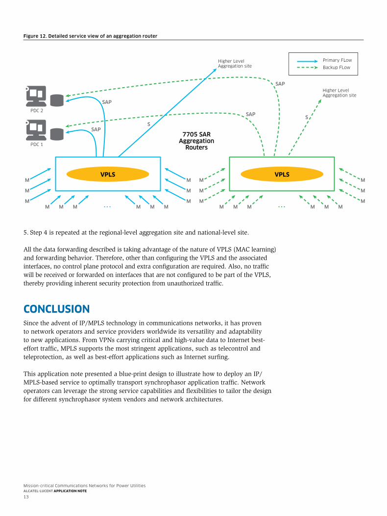
4.EachgatewayrouterattheaggregationsitehastwoSAPinterfacesconnectedtothetwo PDCs in the state-level site. The router delivers the streams received from all PMUs to the PDCs. Each PDC receives two streams (a primary stream and a backup stream)fromeachaggregationrouter(seeFigure12).
Mission-critical Communications Networks for Power UtilitiesAlcAtel-lucent ApplicAtion note
13
Figure 12. Detailed service view of an aggregation router
......
7705 SARAggregation
Routers
Primary FLow
Backup FLow
PDC 2
VPLS
Higher LevelAggregation site
Higher LevelAggregation site
VPLS
PDC 1
M
M
M
M
M
MM M M M M M
VPLSVPLSM
M
M
M
M
MM M M M M M
SAP
SAP
SAP
SS
SAP
5.Step4isrepeatedattheregional-levelaggregationsiteandnational-levelsite.
AllthedataforwardingdescribedistakingadvantageofthenatureofVPLS(MAClearning)andforwardingbehavior.Therefore,otherthanconfiguringtheVPLSandtheassociatedinterfaces, no control plane protocol and extra configuration are required. Also, no traffic willbereceivedorforwardedoninterfacesthatarenotconfiguredtobepartoftheVPLS,thereby providing inherent security protection from unauthorized traffic.
conclusionSince the advent of IP/MPLS technology in communications networks, it has proven to network operators and service providers worldwide its versatility and adaptability tonewapplications.FromVPNscarryingcriticalandhigh-valuedatatoInternetbest-effort traffic, MPLS supports the most stringent applications, such as telecontrol and teleprotection, as well as best-effort applications such as Internet surfing.
This application note presented a blue-print design to illustrate how to deploy an IP/MPLS-based service to optimally transport synchrophasor application traffic. Network operators can leverage the strong service capabilities and flexibilities to tailor the design for different synchrophasor system vendors and network architectures.

Mission-critical Communications Networks for Power UtilitiesAlcAtel-lucent ApplicAtion note
14
acronyMscctV closed circuit television
ces circuit emulation service
frr fast reroute
hmi human machine interface
iP internet Protocol
iPtV internet Protocol television
LaN Local area Network
LsP label switched path
Lsr label switched router
mac media access control
mPLs multiprotocol label switching
Nerc North american electric reliability corporation
oam operations, administration and maintenance
PDc phasor data concentrator
PDh Plesiochronous Digital hierarchy
Pe provider edge
Pim Protocol independent multicast
PmU Phase measurement Unit
Qos Quality of service
rsVP-te resource reservation Protocol with traffic engineering
rtU remote terminal Unit
saP service access Point
sDP service Delivery Point
scaDa supervisory control and data acquisition
sDh synchronous Digital hierarchy
sNmP simple Network management Protocol
soNet synchronous optical Networking
tDm time division multiplexing
VLL virtual leased line
VPLs Virtual Private LaN service
VPN Virtual Private Network
VPrN Virtual Private routed Network

www.alcatel-lucent.com alcatel, Lucent, alcatel-Lucent and the alcatel-Lucent logo are trademarks of alcatel-Lucent. all other trademarks are the property of their respective owners. the information presented is subject to change without notice. alcatel-Lucent assumes no responsibility for inaccuracies contained herein. copyright © 2013 alcatel-Lucent. all rights reserved. NP2013103162eN (November)


![Index [critical-communications-world.com]](https://img.pdfslide.us/doc/110x75/61bd0a9161276e740b0ec0a9/index-critical-communications-worldcom.jpg)