Embed Size (px)
Citation preview
1
MISSION CONTROL CONCEPTS FOR ROBOTIC OPERATIONS (MICCRO)
Dr. Markus Plura 1 SCISYS Deutschland GmbH, 44894 Bochum, Germany
Martin Stelzer 2 German Aerospace Center (DLR), 82230 Wessling-Oberpfaffenhofen, Germany
and
Andreas Ohndorf 3 German Aerospace Center (DLR), 82230 Wessling-Oberpfaffenhofen, Germany
This paper gives an overview of the concept developed within the study “Mission Control Concepts for Robotic Operations (MICCRO)” aiming to find a representative mission control concept for robotic space missions. After presenting these conceptual ideas developed in project phase I, the design, planned utilization and current integration status of a demonstration prototype developed in project phase II to verify the concept in a realistic setup is explained. This end-to-end system based on an on orbit servicing scenario is under integration at the German Aerospace Center (DLR) in Oberpfaffenhofen, Germany. Using this facility, aspects like the handovers between mission phases and consequence on roles and responsibilities can be assessed. A particular emphasis is also put on new functional components like operator support functions on ground or an integrated Mission Control System (MCS) for the satellite platform and the robot in space.
I. Introduction HE recent achievements in telerobotics are an enabling technology for future exploration, on-orbit servicing (OOS) or space debris removal missions. A number of different robotic missions are upcoming. Therefore, the
development of a common concept for robotic mission operations is required to allow an efficient mission setup. The currently ongoing study “Mission Control Concepts for Robotic Operations (MICCRO)” aims to find an abstract, representative mission control concept applicable to multiple future missions that involve robotic systems3.
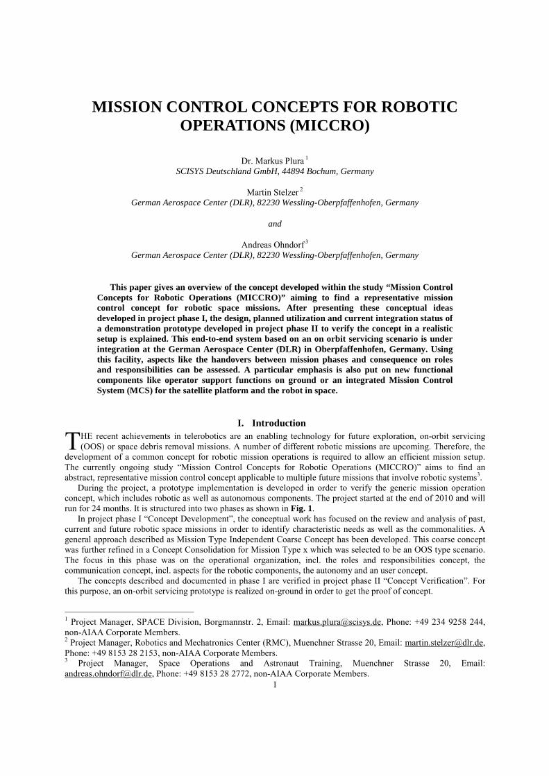
During the project, a prototype implementation is developed in order to verify the generic mission operation concept, which includes robotic as well as autonomous components. The project started at the end of 2010 and will run for 24 months. It is structured into two phases as shown in Fig. 1.
In project phase I “Concept Development”, the conceptual work has focused on the review and analysis of past, current and future robotic space missions in order to identify characteristic needs as well as the commonalities. A general approach described as Mission Type Independent Coarse Concept has been developed. This coarse concept was further refined in a Concept Consolidation for Mission Type x which was selected to be an OOS type scenario. The focus in this phase was on the operational organization, incl. the roles and responsibilities concept, the communication concept, incl. aspects for the robotic components, the autonomy and an user concept.
The concepts described and documented in phase I are verified in project phase II “Concept Verification”. For this purpose, an on-orbit servicing prototype is realized on-ground in order to get the proof of concept.
1 Project Manager, SPACE Division, Borgmannstr. 2, Email: [email protected], Phone: +49 234 9258 244, non-AIAA Corporate Members. 2 Project Manager, Robotics and Mechatronics Center (RMC), Muenchner Strasse 20, Email: [email protected], Phone: +49 8153 28 2153, non-AIAA Corporate Members. 3 Project Manager, Space Operations and Astronaut Training, Muenchner Strasse 20, Email: [email protected], Phone: +49 8153 28 2772, non-AIAA Corporate Members.
T
2
A space robotic mission which will definitely rely on these technology areas is the German Orbital Servicing mission DEOS (“Deutsche Orbitale Servicing Mission”). The primary objectives of DEOS are:
1) Demonstrate the capture of a tumbling, non-cooperative client in low earth orbit
2) De-orbit the mated configuration in a predefined orbit corridor
Other goals are the demonstration of several
Rendezvous & Docking approaches and maintenance activities. Therefore, it is planned to launch a coupled configuration of a servicing satellite together with a client demonstrator into a Low Earth Orbit (LEO). More details regarding DEOS can be found in 1,2
II. Past Experience Within the project team consisting of the SCISYS Deutschland GmbH (coordinator), the DLR Robotics and
Mechatronics Center and the German Space Operations Center (GSOC) expertise in robotics, in spacecraft operations and ground monitoring and control (M&C) as well as data distribution systems are combined.
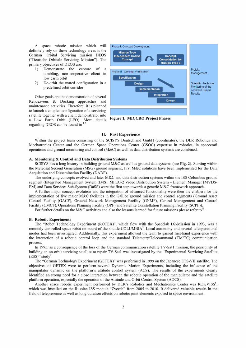
A. Monitoring & Control and Data Distribution Systems SCISYS has a long history in building ground M&C as well as ground data systems (see Fig. 2). Starting within
the Meteosat Second Generation (MSG) ground segment, first M&C solutions have been implemented for the Data Acquisition and Dissemination Facility (DADF).
The underlying concepts evolved and later M&C and data distribution systems within the ISS Columbus ground segment (Integrated Management System (IMS), MPEG-2 Video Distribution System – Element Manager (MVDS-EM) and Data Services Sub-System (DaSS) were the first step towards a generic M&C framework approach.
A further major concept evolution and the integration of advanced functionality were then the enablers for the implementation of five major M&C facilities in the Galileo ground mission and control segments (Ground Asset Control Facility (GACF), Ground Network Management Facility (GNMF), Central Management and Control Facility (CMCF), Operations Planning Facility (OPF) and Satellite Constellation Planning Facility (SCPF)).
For further details on the M&C activities and also the lessons learned for future missions please refer to11.
B. Robotic Experiments The “Robot Technology Experiment (ROTEX)”, which flew with the Spacelab D2-Mission in 1993, was a
remotely controlled space robot on-board of the shuttle COLUMBIA5. Local autonomy and several teleoperational modes had been investigated. Additionally, this experiment allowed the team to gained first-hand experience with the interaction of a robotic control loop and the standard Telemetry/Telecommand (TM/TC) communication process.
In 1995, as a consequence of the loss of the German communication satellite TV-Sat1 mission, the possibility of building an on-orbit servicing satellite to repair TV-Sat1 was investigated by the “Experimental Servicing Satellite (ESS)” study4.
The “German Technology Experiment (GETEX)” was performed in 1999 on the Japanese ETS-VII satellite. The objectives of GETEX were to perform several Dynamic Motion Experiments, including the influence of the manipulator dynamic on the platform’s attitude control system (ACS). The results of the experiments clearly identified an strong need for a close interaction between the robotic operation of the manipulator and the satellite platform operation, especially the operation of the Attitude and Orbit Control System (AOCS).
Another space robotic experiment performed by DLR’s Robotics and Mechatronics Center was ROKVISS6, which was installed on the Russian ISS module “Zvezda” from 2005 to 2010. It delivered valuable results in the field of telepresence as well as long duration effects on robotic joint elements exposed to space environment.
Figure 1. MICCRO Project Phases
3
C. Misson Operations and Approach Navigation DLR has been involved in a number of missions which have been used as intermediate steps on the road to
defining a secure and mature robotic (OOS type) mission concept. The GSOC gained experience with
formation flying through the “Gravity Recovery And Climate Experiment (GRACE)” mission. GRACE was launched in 2002 and consists of two LEO satellites with a nominal along-track separation of about 220km +/- 50km. One of the results with relevance to OOS was the use of E/I-vector separation for a safe transition between GRACE formations7.
With the launch of TanDEM-X8 in 2009, GSOC had to operate a close formation with distances down to a few hundred meters between the second satellite and the first TerraSAR-X spacecraft, which was launched in 2007.
The technology demonstration mission “Prototype Research Instruments and Space Mission technology Advancement” (PRISMA) comprises two satellites initially launched in a stacked configuration9. Launched in 2010, mission operations have been conducted by OHB-Sweden and DLR GSOC. Its main objective is to demonstrate Autonomous Formation Flight (AFF) enabling navigation techniques based on three different sensors: Global Positioning System (GPS), Radio Frequency (RF) and a Vision Based Sensor (VBS). To date, during the mission, PRISMA successfully demonstrated AFF at separation distances from 20 km to less than one meter between the two satellites.
III. Concept for Robotic Missions
A. Organizational Structures During the first study phase, the MICCRO team investigated whether the concept for the organizational
structures and roles & responsibilities in the context of robotic missions should be significantly different than those for other space missions.
An intuitive and proven method for the design and preparation of mission operations is to mirror the space segment’s primary functionalities and interfaces. In that sense, the ground segment infrastructure and organization should minimize the number and complexity of interfaces between distributed components.
An example for introducing a well defined interface on ground is an existing HF link between the corresponding components in space. A robotic Mars exploration mission, for example, consisting of an orbiting spacecraft and a rover on the planet surface, has a well defined interface between the two space segment components. Hence, it is appropriate to cluster the ground segment infrastructure accordingly into two control centers and to operate the space segment components fairly independently.
For an OOS mission like DEOS, there is a very strong coupling between the robotic component, e.g. a manipulator arm, and the satellite platform of the servicer because the manipulator’s motion has a strong fedd-back to the servicer’s attitude. This fact almost inevitably requires some kind of on-board interaction between the Robot Control System (RCS) and the AOCS of the host platform10. Furthermore, during the capture phase, collision avoidance must consider both robotic and platform operation whereby decisions have to be taken on short notice.
2002 2010 20101999 2003 2007
Col-CC: DaSS / IMS / MVDS EM Galileo: GACF / CMCF / GNMFMSG: DADF
SPACE Devision
GETEX / ETS VII ROKVISSROTEX
Robotics and Mechatronics Center (RMC)
2002 2010 20101993 1999 2005
PRISMA ���� 2mGRACE ���� 200 km TanDEM-X ���� 200 m
2002 2010
Space Flight Operations (RB) / German Space Operations Center (GSOC)
2002 2010
Figure 2. MICCRO Team Experiences
4
For this mission type it is therefore essential to conduct platform and robotic operations concurrently from one control room staffed with an integrated Mission or Flight Operations Team (MOT, FOT).
An integrated FOT has key advantages because essential mission elements are in a good overview and short-notice decisions can be based on an integrated information base. Hence, a hierarchical command structure, as usually implemented in control centers, fits well to the general situation. Telepresence and real time operations however introduce however a new dimension into space operations as robotic missions shorten the time scale to make a decision from hours or a couple of minutes down to seconds in worst case. Furthermore, requirement for telepresence conditions limits the response time down to a few hundred milliseconds. Therefore, a direct control loop, parallel to the regular TM/TC communication loop, between the robotic system in space and the robotic payload operator is therefore mandatory. This also closely influences the communication architecture for the robotic mission.
B. Roles & Responsibilities In order to assign the responsibilities between the Flight Director (FD) and the Robotic Operator in more detail,
we analyzed general criteria for designing a concept for roles and responsibilities applicable to robotic missions. Primary questions in this context were: • How quickly must certain decisions be taken? • How much information is required for decision making? • Does the robotic operation include control under telepresence conditions? • Can certain responsibilities be treated independently of others? • Does this imply an integrated mission operations team in a single control room or a distributed team at
separate locations? With respect to the short timescales during telepresence operations, the standard way of commanding by voice
loop from the Robotic Operator via the FD to the Command (CMD) operator has to be modified. Also for other mission subsystems like the AOCS the robotic payload operator needs to get the control authority for the time of the operation. Control authority, nevertheless, should not change, i.e. the FD is always responsible for the complete system and the subsystem operator always responsible for his subsystem.
The roles and responsibilities between the FD and Robotic Operator are similar to those of a Space Shuttle commander and its pilot: While the robotic operator has the control authority for his subsystem, and thus also limited authority for the system during telepresence operations, the FD is always responsible for the entire mission and the general decisions on a time scale of seconds and minutes. These decisions can include also an abort of robotic or telepresence operation. The exact procedure for such an abort of robotic operations depends on the situation and phase. It should be predefined as much as possible and trained thoroughly with representative simulations during the mission preparation phase.
C. Communication Communication infrastructure is an essential key component of all space missions and a number of general
constraints must be respected during its design: • Financial constraints: Cost induces constraints for space missions and this holds especially true for the
ground segment with its ground station network. Carrying out the routine operations phase of a space mission is therefore always a compromise between a higher degree of onboard autonomy or robustness and the number of (costly) ground station contacts required to control the spacecraft. This has naturally implications on design and test of the spacecraft because developing a highly autonomous satellite is more expensive than designing of a “simple” spacecraft that must be commanded from ground more often.
• Connectivity constraints: The required bandwidth, latency time and protocol must be analyzed and also the ground stations that are planned for supporting that mission if they are compliant to those requirements.
• Space segment constraints: The space segment needs to satisfy a number of mission-specific communication requirements. These cannot always be described in advance as it strongly depends on the communication path and possible other spacecraft. An example for special constraints is that imposed by the requirement for telepresence, as described later.
For robotic applications additional constraints need to be considered. Teleoperation allows delayed access to an
application in space. The commanding for each process step has to be identified in advance and all the steps are then
5
assembled in a script-like procedure. Direct interaction, especially in emergency or contingency cases, is usually impossible.
Telepresence enables a direct feedback to an operator of the physical correlation between action and reaction. It allows flexible handling of the current situation, which is especially useful for servicing and repairing. From its basic nature, telepresence is a distributed control loop, which, compared to teleoperation, imposes stricter constraints on the communication link.
Such a telepresence communication link is characterized by bandwidth, jitter, latency, reliability of transmission, contact duration and signal propagation time, and each has direct impact on the quality of service and control. If telepresence involves the feedback of onboard reactions caused by operator-initiated actions, the maximum operational distance reduces to Geostationary Orbit (GEO) height as the total roundtrip time is approx. 500 ms. Current standard ground communication infrastructure was analyzed during the study to find an optimized approach for minimizing jitter and latency.
A satellite’s total ground contact time per orbit can be prolonged through usage of a GEO relay satellite system, e.g. the National Aeronautics and Space Administration’s (NASA) Tracking and Data Relay Satellite System (TDRSS), or a network of ground stations with or without overlapping reception areas. Due to increased complexity and involved hardware, both options have implications on latency.
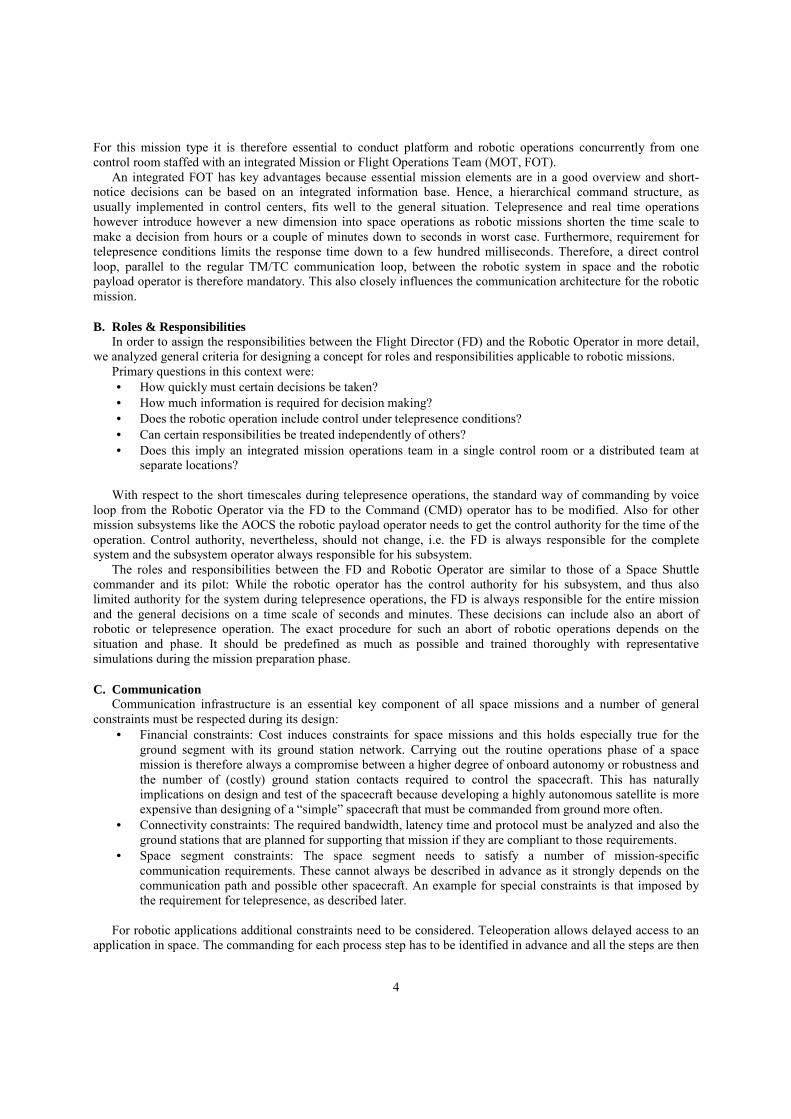
Common to all remote operations is the idea of transferring information via logical/vitual channels, which are de-serialized logical channels for transmission over the physical radio link by multiplexing (see Fig. 3). Available physical link bandwidth is thereby automatically and priority-based shared over all active channels. A flexible adaptation to changing requirements is important as effective available link bandwidth is inversely proportional to signal propagation distance.
Apart from the physical transfer capacity, transmitted data can be categorized into three qualities: 1) Cyclically distributed synchronous data, e.g online telemetry. 2) Acyclically or event-driven distributed, e.g spacecraft telecommands. 3) Synchronous data and asynchronous data, distributed on request, e.g. house-keeping data, file transfer. For data transfer, several protocol proposals from different sources are available, e.g. CCSDS, ECSS and
TCP/IP. As these standards are widely used, the communication design of MICCRO is also based on the standards.
D. Autonomy Autonomy has many different aspects for robotic missions and has been deeply investigated in the course of the
MICCRO study. Autonomous functions may be spread all over the application domains of a space mission, e.g. Guidance Navigation and Control (GNC); Failure Detection, Isolation and Recovery (FDIR); Managing and Intelligent Sensing and Data Handling, both in the space and the ground segment. A variety of technologies to achieve low level autonomy are already commonly in use. Examples are schedulers, event-based execution systems, star trackers with lost-in-space acquisition capabilities, etc. Several types of autonomy potentially beneficial for robotic space missions were discussed in the course of the MICCRO study.
Special requirements to space autonomy have been identified for the approach and docking phase of an OOS mission. Due to hardware performance limitations it may not be feasible to permanently update the complete dynamics model on board the servicer satellite but transfer the computational load to the ground instead. This requires a closed loop between onboard sensors, actuators and ground equipment. It is important to note that by this approach the robotic control authority is implicitly moved to the ground – especially during telepresence activities – which in turn introduces a new potential failure scenario in case of a link loss to the space segment. A solution could be a collision avoidance maneuver (CAM) based on an up-to-date state of the system which is regularly uploaded to the servicer and automatically activated in case of a major problem.
When considering on-ground autonomy concepts, it can be employed in two ways: 1) Operations can be directly affected, e.g. by a procedure execution (PEX) executing event-based tasks as an
autonomous reaction. 2) On the other hand, an autonomy components may be intentionally decoupled from the real space system
and instead provide its output to an operator as a suggested solution (assistance system).
Figure 3. Virtual Communication Channels
6
The latter autonomy component is used within MICCRO as an assistance system while control authority is kept
with human personnel.
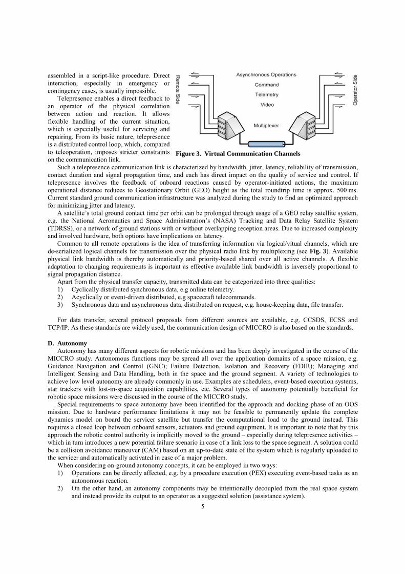
E. User Interface Human Machine Interfaces (HMI) allow operators not only to obtain information about the current state of a
system but also to change the system state, if required. For a robotic satellite mission, the Monitoring & Control (M&C) software suite SCOS-2000 and the SCISYS egmc² framework provide well-proven HMIs that have been already used successfully to support other space missions. The new robotic mission element, however, demands additional HMI component.
Generally, there are three categories of data which need to be presented to human operators through HMIs: 1) Satellite uplink/downlink data including conventional command and telemetry data as well as data
transmitted through real-time channels 2) Data exchanged between operators and other on-ground applications such as ground data, ground
autonomy, video processing and similar assistance applications 3) Management and status data for all ground facilities including means to start, stop, reset and supervise
these systems These data should be visualized through HMI components which plug into a standardized application framework
(Fig. 5). The composition of these components varies with respect to the responsibilities of the particular operator, whereas some components may be repeatedly used for several or all interfaces. From experiences gathered during past missions the following requirements from the robotics viewpoint have been compiled:
• The user interfaces for the robot operators should comply with high level software ergonomics standards. • For the same sake the robotics operator should be provided an augmented virtual reality display of the
situation on board the spacecraft. • HMI components common to all robotics team members should comprise a state summary of the overall
systems on-ground, on-board and a more detailed summary of the robotics subsystem. • A mission timeline should depict planned and actual procedures and events as well as externally triggered
events, e.g. eclipse phases. • A video display should alleviate imagination of the situation on-board for all robotics team members. • High-end haptic input devices should enable the robotics operator to actually feel what is going on on-
board during telepresent manipulation.
SCOS HMI
RCS HMIRCS VIDEO
Haptic HMIs
Figure 4. User Interfaces
7
IV. Demonstration Prototype
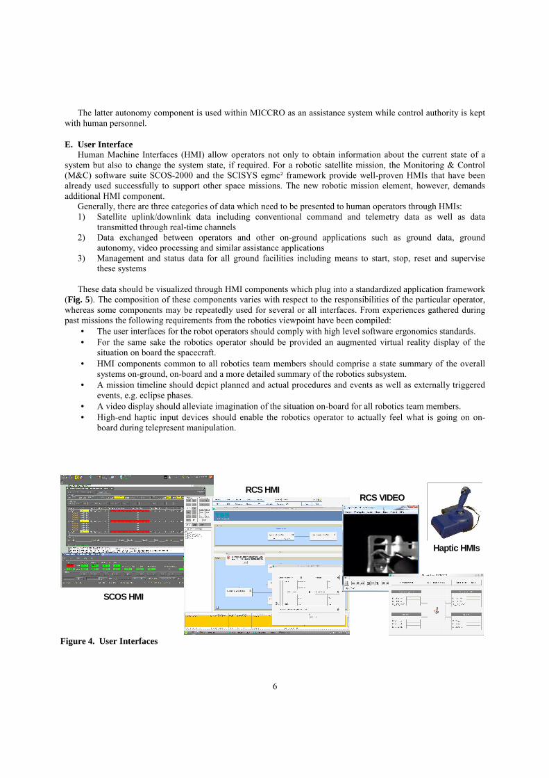
A. Design In order to setup a demonstration scenario for an OOS type mission, we use standard building blocks as already
used in different mission setups wherever possible. This can not be done for all components as also some new components have been implemented (Fig. 5).
The Robotics Control System (RCS) consists of many different subcomponents responsible for the monitoring and control of the robotic component. For the realtime telecommands (RT TC) a dedicated VxWorks based platform is coupled with a high performance haptic device as already shown in Fig. 4. In addition to the RT data handling an additional server platform is designed to handle all non realtime (non-RT) data flows. The server is responsible for receiving all housekeeping data from the robotic system, configuring the parameters for the RT data transmission and also the non-RT commanding of the robotic components. These commands as well as the housekeeping data for the robot are transferred via standard spacecraft TM/TC and the interface towards the SCOS based on its External Interface (EXIF). The server itself is implemented on the well proven egmc² framework developed by SCISYS and the interface towards the SCOS has been implemented for this purpose. The server also orchestrates a ground autonomy subcomponent. It is based on an adaptive short term planning system that is working on problems defined in the Problem Domain Definition Language (PDDL). As the latest telemetry can be fed into this planning system it can be used as an assisting early warning system to the robotics operator. Further the RCS also hosts all HMI components that are specific to the robotic component. Also the on board Video data is received and visualized.
The Mission Control System (MCS) is the software and hardware solution running in the Mission Control Center to monitor and control the space segment. It has to provide the functionality to connect to one or a network of ground stations. Therefore, it needs to receive telemetry transfer frames data based on data stream and virtual channel id, as defined in given standards, to deliver telecommand frames and also to receive administration messages of the executing NCTRS/NIS system. For the MICCRO demonstrator we are using SCOS 2000 by ESA, as it is already used within the GSOC for other missions and it is considered as the de facto standard for European space missions. A specific mission database (MIB) has been created for the project.
The Communication Gateway is a new component that was designed for supporting robotic missions within the ground segment. It is a central component to support the routing of different virtual channels as explained in the communication concept via the protocol standards usually used for the standard satellite TM/TC. The RT TC and Video data is received, converted and multiplexed into the standard satellite communication. For this the full protocol stack has been implemented and also sophisticated multiplexers are implemented. Towards the simulated space link, the frames are transmitted over a UDP link as no ground station and physical RX/TX equipment is used for the simulator. The Communication Gateway is the enabling component implemented in C++ to transfer the different virtual channels mutiplexes according to given priorities on the standard protoccols.
For the different terrestrial and space link simulators based on the open source tool WANem are implemented to be able to simulate the effects of latency, jitter and packet losses. Two terrestrial links between the control center (SLE network for TM/TC and SDH-E3 link for Video and RT TC) are simulated. For the space link the caracteristics can be easiliy adjusted to show the effects on robotic operations.
The Onboard MUX which is based on the same application code as the Communication Gateway acts as its counterpart to multiplex or de-multiplex the data send to the ground or received from ground. Usually the data as
Robotic Control System
Mission Control System
EXIF
Ground Segment Space Segment
34 Mbps SDH-E3
Sim
Com.Gateway
2 MbpsSLE Sim
Robotic Payload (ROKVISS)
Spacecraft SIM
TM/TCFrames
VideoRT TCTM/TC
TM/TC
VideoRT TCTM/TC
TM/TC
Space Link Sim
Onboard MUX
Figure 5. Demonstrator Design
8
send by the ground station would be de-multiplexed based on the virtual channel ID or the APID onboard the spacecraft. This is now done in the Onboard MUX and the data to the robotic component is separated from the TM/TC towards the satellite platform simulator.
For the Robotic Payload the engineering model of the ROKVISS experiment will be used. It was already in use for the preparation of the experiment in space and it comprises the robot and the VxWorks based control platform for the robot.
In order to allow a simulation of the satellite platform an addition simulation tool GSTVi by ESA is used to allow an interfacing to the data as send by SCOS. The powerful SW suite is deployed in a minimal configuration to answer the commands send and to create a minimal set of telemetry. This telemetry is created by a satellite model simulating a LEO orbit as applicable for the envisaged OOS scenario.
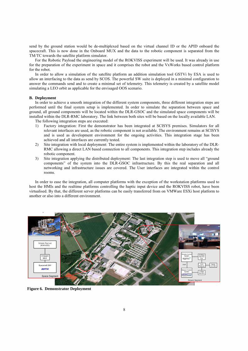
B. Deployment In order to achieve a smooth integration of the different system components, three different integration steps are
performed until the final system setup is implemented. In order to simulate the separation between space and ground, all ground components will be located within the DLR-GSOC and the simulated space components will be installed within the DLR-RMC laboratory. The link between both sites will be based on the locally available LAN.
The following integration steps are executed: 1) Factory integration: First the demonstrator has been integrated at SCISYS premises. Simulators for all
relevant interfaces are used, as the robotic component is not available. The environment remains at SCISYS and is used as development environment for the ongoing activities. This integration stage has been achieved and all interfaces are currently tested.
2) Site integration with local deployment: The entire system is implemented within the laboratory of the DLR-RMC allowing a direct LAN based connection to all components. This integration step includes already the robotic component.
3) Site integration applying the distributed deployment: The last integration step is used to move all “ground components” of the system into the DLR-GSOC infrastructure. By this the real separation and all networking and infrastructure issues are covered. The User interfaces are integrated within the control rooms.
In order to ease the integration, all computer platforms with the exception of the workstation platforms used to
host the HMIs and the realtime platforms controlling the haptic input device and the ROKVISS robot, have been virtualised. By that, the different server platforms can be easily transferred from on VMWare ESXi host platform to another or also into a different environment.
Figure 6. Demonstrator Deployment
9
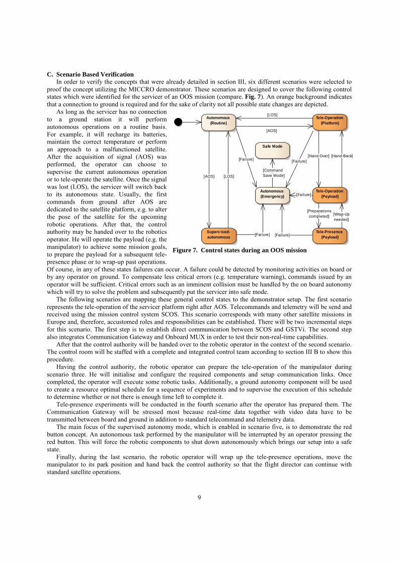
C. Scenario Based Verification In order to verify the concepts that were already detailed in section III, six different scenarios were selected to
proof the concept utilizing the MICCRO demonstrator. These scenarios are designed to cover the following control states which were identified for the servicer of an OOS mission (compare. Fig. 7). An orange background indicates that a connection to ground is required and for the sake of clarity not all possible state changes are depicted.
As long as the servicer has no connection to a ground station it will perform autonomous operations on a routine basis. For example, it will recharge its batteries, maintain the correct temperature or perform an approach to a malfunctioned satellite. After the acquisition of signal (AOS) was performed, the operator can choose to supervise the current autonomous operation or to tele-operate the satellite. Once the signal was lost (LOS), the servicer will switch back to its autonomous state. Usually, the first commands from ground after AOS are dedicated to the satellite platform, e.g. to alter the pose of the satellite for the upcoming robotic operations. After that, the control authority may be handed over to the robotics operator. He will operate the payload (e.g. the manipulator) to achieve some mission goals, to prepare the payload for a subsequent tele-presence phase or to wrap-up past operations. Of course, in any of these states failures can occur. A failure could be detected by monitoring activities on board or by any operator on ground. To compensate less critical errors (e.g. temperature warning), commands issued by an operator will be sufficient. Critical errors such as an imminent collision must be handled by the on board autonomy which will try to solve the problem and subsequently put the servicer into safe mode.
The following scenarios are mapping these general control states to the demonstrator setup. The first scenario represents the tele-operation of the servicer platform right after AOS. Telecommands and telemetry will be send and received using the mission control system SCOS. This scenario corresponds with many other satellite missions in Europe and, therefore, accustomed roles and responsibilities can be established. There will be two incremental steps for this scenario. The first step is to establish direct communication between SCOS and GSTVi. The second step also integrates Communication Gateway and Onboard MUX in order to test their non-real-time capabilities.
After that the control authority will be handed over to the robotic operator in the context of the second scenario. The control room will be staffed with a complete and integrated control team according to section III B to show this procedure.
Having the control authority, the robotic operator can prepare the tele-operation of the manipulator during scenario three. He will initialise and configure the required components and setup communication links. Once completed, the operator will execute some robotic tasks. Additionally, a ground autonomy component will be used to create a resource optimal schedule for a sequence of experiments and to supervise the execution of this schedule to determine whether or not there is enough time left to complete it.
Tele-presence experiments will be conducted in the fourth scenario after the operator has prepared them. The Communication Gateway will be stressed most because real-time data together with video data have to be transmitted between board and ground in addition to standard telecommand and telemetry data.
The main focus of the supervised autonomy mode, which is enabled in scenario five, is to demonstrate the red button concept. An autonomous task performed by the manipulator will be interrupted by an operator pressing the red button. This will force the robotic components to shut down autonomously which brings our setup into a safe state.
Finally, during the last scenario, the robotic operator will wrap up the tele-presence operations, move the manipulator to its park position and hand back the control authority so that the flight director can continue with standard satellite operations.
Superv ised- autonomous
Autonomous (Routine)
Tele-Presence (Payload)
Tele-Operation (Platform)
Tele-Operation (Payload)
Autonomous (Emergency)
Safe Mode
[LOS]
[AOS]
[AOS]
[Failure]
[Wrap-Upneeded]
[Fai lure][Fai lure]
[Hand-Over][Failure]
[LOS]
[Preparationscompleted]
[Hand-Back]
[Failure]
[CommandSave Mode]
Figure 7. Control states during an OOS mission
10
V. Conclusion and Outlook The concepts for robotic mission operations as described in section III, are applied for the setup of a
demonstration prototype. This system demonstrator will be used to provide the proof of concept. This demonstration will be performed in late summer in a realistic scenario within the GSOC. The selected mission type is agreed to be an on-orbit servicing mission incorporating robotic manipulators on board the spacecraft. This special scenario has been selected as it induces a number of challenging requirements in all areas discussed in this paper and by that allows demonstrating most aspects of the common mission operations concept.
The results extracted will also be beneficial for future robotic missions. For these missions the guidelines and also prototype implementations can be used to set up the ground segment in a harmonized way. With view on the upcoming DEOS mission, the conceptual ideas for this robotic OOS type mission are prepared and can be used for the mission preparation.
Acknowledgments The MICCRO project is funded by the Space Agency of the German Aerospace Centre (DLR) with federal funds
from the Federal Ministry of Economics and Technology in accordance with the parliamentary resolution of the German Parliament. (Grant no. 50RA1015 and Grant ID 50 RA 1016).
References 1Reintsema, D., Thaeter, J., Rathke, A., Naumann, W., Rank, P., Sommer, J., “DEOS The German Robotics Approach to Secure and De-Orbit Malfunctioned Satellites from Low Earth Orbit”, i-SAIRAS, August 29- September 1, 2010, Sapporo, Japan 2Sellmaier, F., Boge, T., Spurmann, J., Gully, S., Rupp, T., Huber, F., „On-Orbit Servicing Missions: Challenges 2010 Conference, Huntsville, Alabama, USA, AIAA 2010-2159 3F. Sellmaier, M. Plura, M. Stelzer, A. Ohndorf, H. Müller, and K. Landzettel, “Mission Operation Concepts For Robotic Missions”, 62nd International Astronautical Congress, 03-07. Okt. 2011, Cape Town, South Africa, 2011. 4Settelmeyer, E., Lehrl, E., Oesterlin, W., Hartmann, R., Landzettel, K., “The Experimental Servicing Satellite – ESS”, IARP 98-c-14, 1998 5Landzettel, K., Preusche, C., Albu-Schäffer, A., Reintsema, D., Rebele, B., Hirzinger, G., “Robotic On- Orbit Servicing - DLR's Experience and Perspective”, Proceedings of the 2006 IEEE/RSJ, International Conference on Intelligent Robots and Systems, October 9 - 15, 2006, Beijing, China 6Landzettel, K., Albu-Schäffer, A., Brunner, B., Beyer, A., Gruber, R., Krämer, E., Preusche, C., Reintsema, D., Schott, J., Steinmetz, H.-J., Hirzinger, G., “ROKVISS: Verification of Advanced Light Weight Robotic Joints and Tele-Presence Concepts for Future Space Missions”, ASTRA 2006 – the 9th ESA Workshop on Advanced Space Technologies for Robotics and Automation, ESA's research and technology centre, ESTEC, Noordwijk, Netherlands, 28-30 November 2006 and solutions for Spacecraft Operations“, AIAA SpaceOps 7Montenbruck, O., Kirschner, M., D’Amico, S., Bettadpur, S., “E/I-vector separation for a safe switching of the GRACE formation“, Aerospace Science and Technology 10 (2006) 628-635 8D’Amico, S., and Montenbruck, O., “Proximity Operations of Formation-Flying Spacecraft Using an Eccentricity/Inclination Vector Separation”, Journal of Guidance, Control and Dynamics, Vol.29, No. 3, May- June, 2006, pp. 554-563 9Persson, S., Bodin, P., Gill, E., Harr, J., Jörgensen, J., „PRISMA – an Autonomous Formation Flying mission”, ESA Small Satellite Systems and Services Symposium (4S), 25-29 September 2006, Sardinia, Italy 10K. Landzettel, G. Schreiber, B. Brunner, B. Steinmetz, K. Deutrich, and G. Hirzinger, “DLR/NASDA’s Joint Robotics Experiments on ETS VII”, in J. NASDA (Editor), ETS VII Symposium, Tokyo, Japan, 14.03.2000, 2000, pp. 136–145 11S. Recher, C. Stoecker, and M. Brueggen, „Inputs to Future Missions: Lessons Learned from 10 Years Building Ground M&C Systems“, in Procedings of SpaceOps 2012, Stockholm, Sweden, 2012.