Embed Size (px)
Citation preview

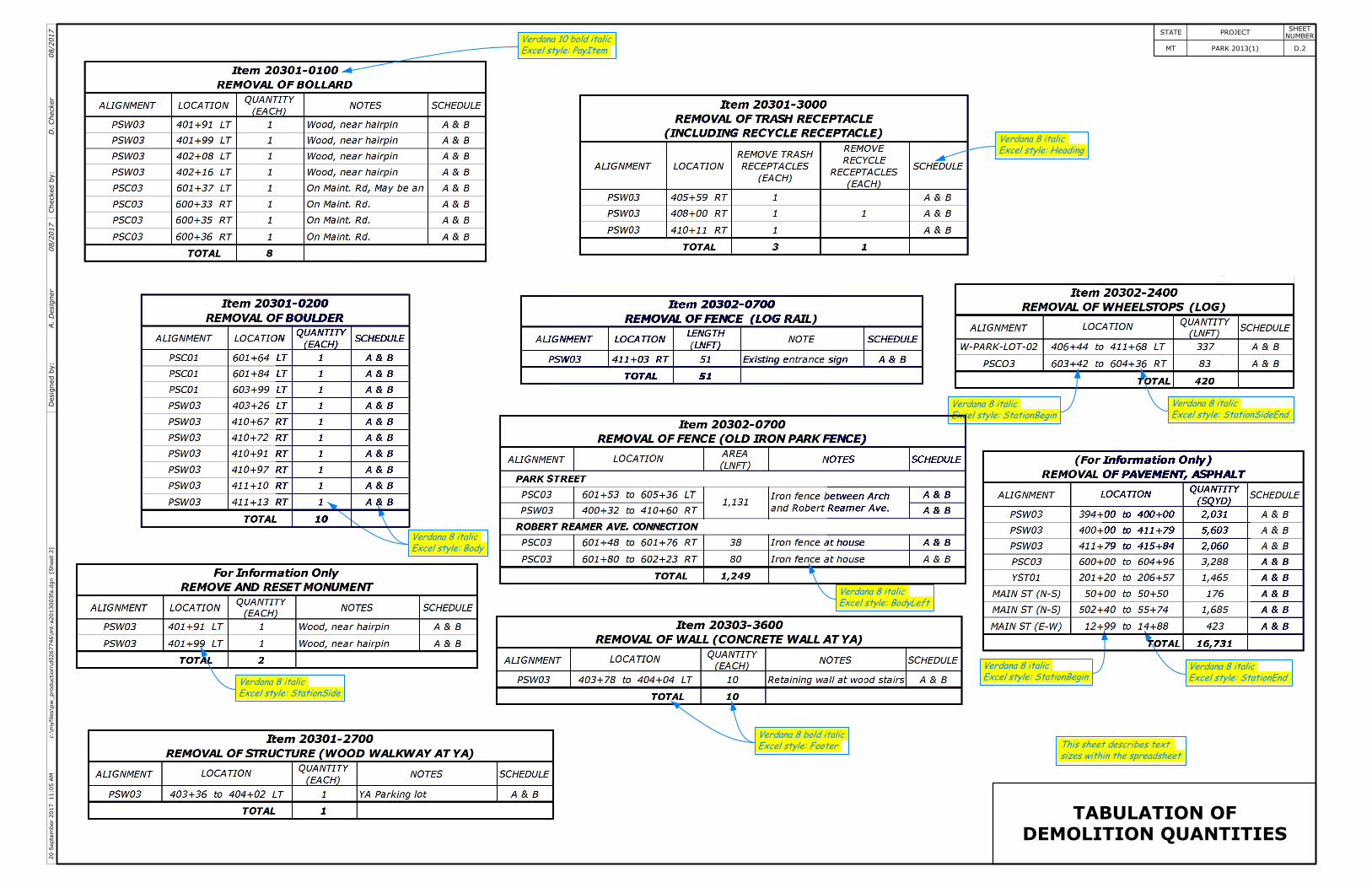
DEMOLITION QUANTITIES
TABULATION OF
FOOTNOTE:
through CO for delivery to MDT.
light poles along Hwy 89 (2nd St.) and coordinate
of light poles along Park St. Contractor to remove
Coordinate with NWE through CO for removal [1]
(US International sample similar)
Master Units: US Survey Feet
at Scale 1 and text at the default size.
Unless otherwise noted place cells
1.00000Size equals
Place spreadsheet as link.
from model properties.
"Sheet Number" comes
Use enter data fields.
Note HeadingText Style:
(Field can be overwritten)
to obtain good appearance.
Line Length shortened to 24
"Sheet Name" model property.
Automatic field references the
TX = 0:0.16
Title (Vert)Text Style:
Fill in enter data fields
NotesText Style:
]Sheet
1[
c:\m
yfiles\p
w_production\d0267746\mt-
a2013003fa.d
gn
2:17
PM
27
Septe
mber
2017
STATE PROJECTNUMBER
SHEET
1D.MT PARK 2013(1) Checked
by:
Desig
ned
by:
A.
Desig
ner
D.
Checker
08/2017
08/2017
DEMOLITION QUANTITIES
TABULATION OF
]Sheet
2[
c:\m
yfiles\p
w_production\d0267746\mt-
a2013003fa.d
gn
11:05
AM
20
Septe
mber
2017
STATE PROJECTNUMBER
SHEET
2D.MT PARK 2013(1) Checked
by:
Desig
ned
by:
A.
Desig
ner
D.
Checker
08/2017
08/2017
Excel style: StationSide
Verdana 8 italic
Excel style: BodyLeft
Verdana 8 italic
Excel style: StationBegin
Verdana 8 italic
Excel style: StationEnd
Verdana 8 italic
Excel style: StationSideEnd
Verdana 8 italic
Excel style: StationBegin
Verdana 8 italic
Excel style: Heading
Verdana 8 italic
Excel style: PayItem
Verdana 10 bold italic
sizes within the spreadsheet
This sheet describes text
Excel style: Body
Verdana 8 italic
Excel style: Footer
Verdana 8 bold italic
105
PT
106+
58.0
3
PC
108+
49.4
4
110
PT
110+38.4
7
4,7
43.0
2
103+
80
4,7
53.8
2
+6.0000
%
-0.3429%
275' VC
K = 43
SSD = 308'
109+
00
4,7
52.0
4
100' VC
K = 644
SSD = 6999'
-0.4982%
Text Style: Heading
Dimension Style: Limits/Section
at a scale of 1
Bring in North arrow
]U
SC
Sheet
[c:\m
yfiles\p
w_production\d0267745\of2
4701_fa.d
gn
1:42
PM
31
August
2017
STATE PROJECTNUMBER
SHEET
D.2OR PFH 247(1) Checked
by:
Desig
ned
by:
A.
Desig
ner
D.
Checker
08/2017
08/2017
D
e= 0.056
L= 512.15'
T= 278.52'
R= 525.00'
D
e= 0.032
L= 189.02'
T= 94.62'
R= 1,650.00
Existing pavement surface
End
subexcavation
104+
25
CONNECTION DETAIL
Aggregate base
Asphalt pavement
backfill (select borrow)
Subexcavation
Section
No.1,
See
Sheet
C.2,for
Typical
Matc
hexisting
pave
ment
102+
00
APPROACH SYMBOL
Mainline station Type
Approach grade
171+04
-4.8
%R=3.5'
Turning radii (if different
from standard, see
Sheet E.14)
N
reset fence, wood
Remove and
101+98 to 103+61
Proposed edge of pavement
Slope stake limits
Line to be constructed
Existing edge of pavement
Slope stake limits
91
+0
11
%1-
A
CUYD
EXC.
CUYD
EMB.
4700
110+00107+50105+00102+50
4700
4710 4710
4720 4720
4730 4730
4740 4740
4750 4750
4760 4760
4770 4770
4780 4780
377
176
Subexcavation
Profile grade
Existing ground
Dimension Style: Feet-inch
Text Style: Note
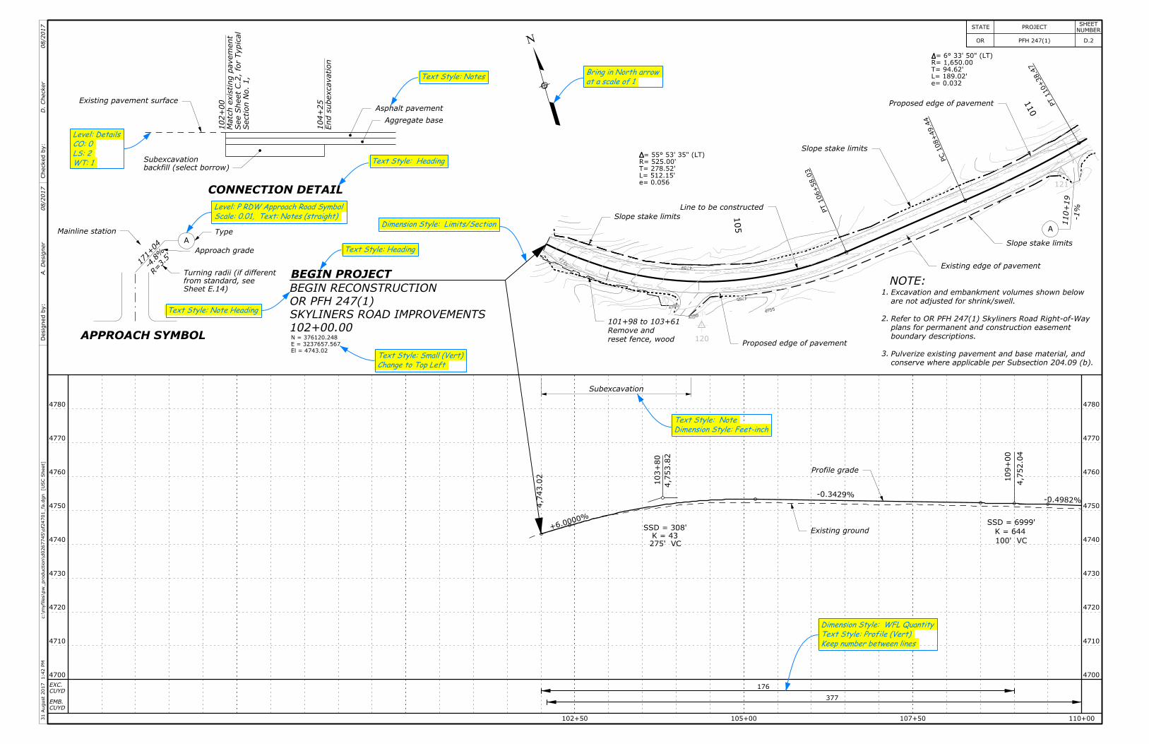
NOTE:Excavation and embankment volumes shown below
are not adjusted for shrink/swell.
Refer to OR PFH 247(1) Skyliners Road Right-of-Way
plans for permanent and construction easement
boundary descriptions.
Pulverize existing pavement and base material, and
conserve where applicable per Subsection 204.09 (b).
1.
2.
3.
WT: 1
LS: 2
CO: 0
Level: Details
A
Scale: 0.01, Text: Notes (straight)
Level: P RDW Approach Road Symbol
Keep number between lines
Text Style: Profile (Vert)
Dimension Style: WFL Quantity
El = 4743.02
E = 3237657.567
N = 376120.248
102+00.00
SKYLINERS ROAD IMPROVEMENTS
OR PFH 247(1)
BEGIN RECONSTRUCTION
Change to Top Left
Text Style: Small (Vert)
Text Style: Note Heading
Text Style: Heading
Text Style: Notes
BEGIN PROJECT
Slope stake limits
Proposed edge of pavement
4745
4750
4755
4755
4755
4755
CP
121
CP
120
110
PT
110+
38.4
7
PC
111+
21.1
2
115
PT
115+
47.2
1
120
125
117+
75
4,7
47.6
8
-0.4982%
-3.5600%350' VC
K = 114
SSD = 527'
124+
75
4,7
22.7
6
350' VC
K = 117
at a scale of 1
Bring in North arrow
CUYD
EXC.
CUYD
EMB.
4690 4690
4700 4700
4710 4710
4720 4720
4730 4730
4740 4740
4750 4750
4760 4760
4770 4770
Keep number between lines
Text Style: Profile (Vert)
Dimension Style: WFL Quantity
D
R= 1,650.00'
T= 94.62'
L= 189.02'D
R= 1,400.00'
T= 214.70'
L= 426.09'
e= 0.036
115+
87.0
2
B
117+46.5
4
Slope stake limits
Existing edge of pavementProposed edge of pavement
Proposed edge of pavement
Existing edge of pavementSlope stake limits
Line to be constructed
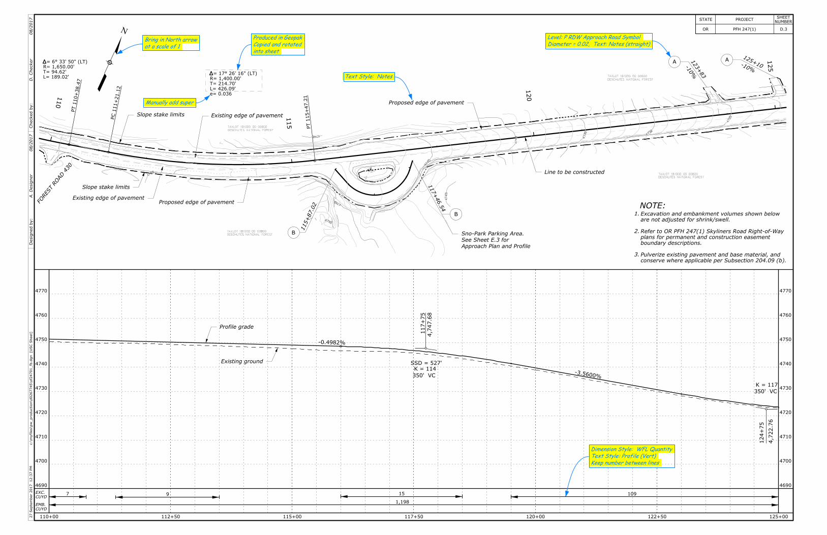
NOTE:1.
2.
3.
Excavation and embankment volumes shown below
are not adjusted for shrink/swell.
Refer to OR PFH 247(1) Skyliners Road Right-of-Way
plans for permanent and construction easement
boundary descriptions.
Pulverize existing pavement and base material, and
conserve where applicable per Subsection 204.09 (b).
-10%
125+10A1
23+83
-10
%
A
N
110+00 112+50 115+00 117+50 120+00 122+50 125+00
7
1,198
109
Approach Plan and Profile
See Sheet E.3 for
Sno-Park Parking Area.
Text Style: Notes
FO
REST
RO
AD
430
Checked
by:
Desig
ned
by:
A.
Desig
ner
D.
Checker
08/2017
08/2017
into sheet
Copied and rotated
Produced in Geopak
Manually add super
B
Profile grade
Existing ground
Diameter = 0.02, Text: Notes (straight)
Level: P RDW Approach Road Symbol
]U
SC
Sheet
[c:\m
yfiles\p
w_production\d0267745\of2
4701_fb.d
gn
12:37
PM
27
Septe
mber
2017
STATE PROJECTNUMBER
SHEET
D.3OR PFH 247(1)
9 15
4725
4730
4735
4740
4740
4745
4745
4750
4750
4750
4755
GPS
4
DESCHUTES NATIONAL FOREST
TAXLOT 181000 00 00800
DESCHUTES NATIONAL FOREST
TAXLOT 181000 00 00800
DESCHUTES NATIONAL FOREST
TAXLOT 181000 00 00800
DESCHUTES NATIONAL FOREST
TAXLOT 181000 00 00800
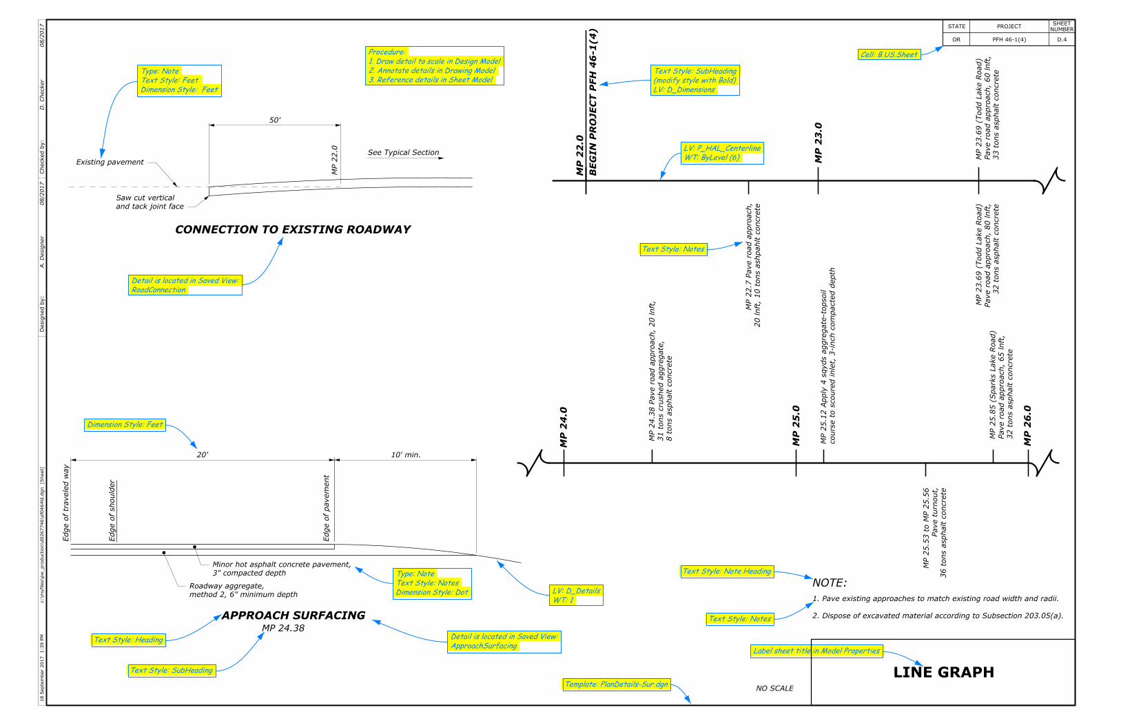
APPROACH SURFACING
Edge
ofshould
er
Edge
ofpave
ment
Edge
oftr
avele
dway
MP 24.38
20'
3" compacted depth
Minor hot asphalt concrete pavement,
method 2, 6" minimum depth
Roadway aggregate,
10' min.
CONNECTION TO EXISTING ROADWAY
See Typical Section
MP
22.0
and tack joint face
Saw cut vertical
Existing pavement
50'
20lnft,10to
ns
ashpahlt
concrete
MP
22.7
Paveroad
approach,
32to
ns
asphalt
concrete
Paveroad
approach,80lnft,
MP
23.6
9(Todd
Lake
Road)
33to
ns
asphalt
concrete
Paveroad
approach,60lnft,
MP
23.6
9(Todd
Lake
Road)
MP
22.0
BE
GI
NP
ROJE
CT
PF
H46-1(4)
MP
23.0
36to
ns
asphalt
concrete
Paveturnout,
MP
25.5
3to
MP
25.5
6
8to
ns
asphalt
concrete
31to
ns
crushed
aggregate,
MP
24.3
8Paveroad
approach,20lnft,
courseto
scouredinlet,
3-in
ch
co
mpacte
ddepth
MP
25.1
2Apply
4sqyds
aggregate-to
psoil
32to
ns
asphalt
concrete
Paveroad
approach,65lnft,
MP
25.8
5(Sparks
Lake
Road)
MP
24.0
MP
25.0
MP
26.0
NO SCALE
RoadConnection
Detail is located in Saved View:
ApproachSurfacing
Detail is located in Saved View:
LINE GRAPH
HeadingText Style:
SubHeadingText Style:
3. Reference details in Sheet Model
2. Annotate details in Drawing Model
1. Draw detail to scale in Design Model
Procedure:
Note HeadingText Style:
NotesText Style:
Label sheet title in Model Properties
1WT:
D_DetailsLV:
ByLevel (6)WT:
P_HAL_CenterlineLV:
NotesText Style:
NOTE:
D_DimensionsLV:
(modify style with Bold)
SubHeadingText Style:
FeetDimension Style:
DotDimension Style:
NotesText Style:
NoteType:
Template: PlanDetails-Sur.dgn
B.US.SheetCell:
2. Dispose of excavated material according to Subsection 203.05(a).
1. Pave existing approaches to match existing road width and radii.
]Sheet
[c:\m
yfiles\p
w_production\d0267746\of0
464ld.d
gn
1:39
PM
18
Septe
mber
2017
STATE PROJECTNUMBER
SHEET
4D.OR PFH 46-1(4)Checked
by:
Desig
ned
by:
A.
Desig
ner
D.
Checker
08/2017
08/2017
FeetDimension Style:
FeetText Style:
NoteType:
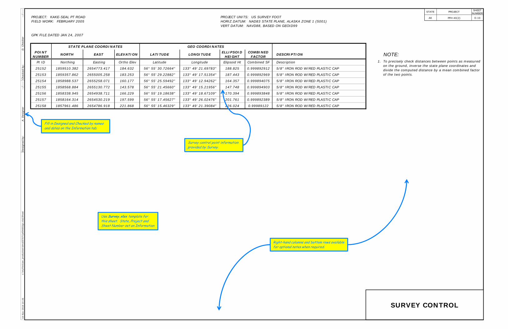
GPK FILE DATED JAN 24, 2007
STATE PLANE COORDINATES GEO COORDINATES POINT
NUMBER NORTH EAST ELEVATION LATITUDE LONGITUDE ELLIPSOID HEIGHT
COMBINED FACTOR DESCRIPTION NOTE:
Pt ID Northing Easting Ortho Elev Latitude Longitude Elipsoid Ht Combined SF Description 1.
25152 1859510.382 2654773.417 184.632 56° 55' 30.72664" 133° 49' 21.69783" 188.825 0.999892912 5/8" IRON ROD W/RED PLASTIC CAP
25153 1859357.862 2655005.258 183.253 56° 55' 29.22882" 133° 49' 17.51354" 187.443 0.999892969 5/8" IRON ROD W/RED PLASTIC CAP
25154 1858988.537 2655258.071 160.177 56° 55' 25.59492" 133° 49' 12.94262" 164.357 0.999894075 5/8" IRON ROD W/RED PLASTIC CAP
25155 1858568.884 2655130.772 143.578 56° 55' 21.45660" 133° 49' 15.21956" 147.748 0.999894903 5/8" IRON ROD W/RED PLASTIC CAP
25156 1858338.945 2654938.711 166.229 56° 55' 19.18638" 133° 49' 18.67109" 170.394 0.999893848 5/8" IRON ROD W/RED PLASTIC CAP
25157 1858164.314 2654530.219 197.599 56° 55' 17.45627" 133° 49' 26.02476" 201.761 0.999892389 5/8" IRON ROD W/RED PLASTIC CAP
25158 1857961.486 2654786.918 221.868 56° 55' 15.46329" 133° 49' 21.39084" 226.024 0.99989122 5/8" IRON ROD W/RED PLASTIC CAP
PROJECT: KAKE-SEAL PT ROAD FIELD WORK: FEBRUARY 2005
PROJECT UNITS: US SURVEY FOOT HORIZ.DATUM: NAD83 STATE PLANE, ALASKA ZONE 1 (5001) VERT DATUM: NAVD88, BASED ON GEOID99
To precisely check distances between points as measured on the ground, inverse the state plane coordinates and divide the computed distance by a mean combined factor of the two points.
c:\m
yfile
s\pw
_pro
duct
ion\
dms0
3707
\[af
0400
2gz.
xlsx
]She
et18
-Nov
-201
6 10
:45
A.
Des
igne
r --
/---
-D
. Che
cker
--
/---
-D
esig
ned
by:
Che
cked
by:
STATE PROJECT
D.10
SHEET NUMBER
PFH 40(2) AK
SURVEY CONTROL
Use Survey.xlsx template for this sheet. State, Project and Sheet Number set on Information
Fill in Designed and Checked by names and dates on the Information tab.
Right-hand columns and bottom rows available for optional notes when required.
Survey control point information provided by Survey.
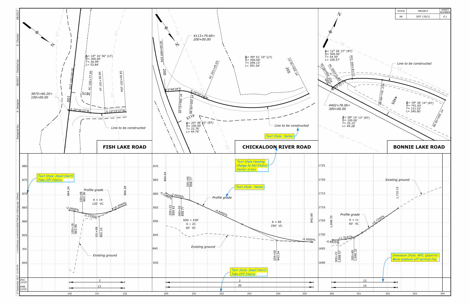
Saved View: Fish_HASaved View: Chick_HASaved View: Bonnie_HA
PC
100+
77.0
0
PT
101+
30.8
4
PO
T102+
05.8
1
PO
T100+
00.0
0
R= 300.00'
T= 26.99'
L= 53.84'
D
N
S20°36'33"W S10°19'37"W
100
3875
N
PO
T200+
00.0
0
PC
200+
51.0
9
PT
200+
95.8
6
D
R= 100.00'
T= 22.76'
L= 44.76'
PC
201+
45.0
3
D
R= 450.00'
T= 209.13'
L= 391.54'
PT
205+36.5
7
S18°50'24"W
S6°48'28"E
4115
200
205
PO
T300+00.0
0
PT
304+
30.5
8
D
R=741.93'T=121.52'L=240.90'
PC
C301+
89.6
8
PC
C300+
81.1
1
PC
300+31.8
3
D
R= 500.00'
T= 54.50'
L= 108.57'
D
R=100.00'T=25.15'L=49.28'
N
4405
N83°3
2'1"
E300
100+
18
863.9
8
-2.0000%
864.3
4
100+
48
863.3
8
-2.1330%
101+
08
862.1
0
+4.309
0%
866.2
8
120' VC
K = 19
200+
22
859.4
3
-5.5280%
860.6
4
200+
55
858.7
7
-2.0000%
200+
85
858.1
7
204+
00
843.5
4
-4.6456%
-0.5000%
842.8
9
250' VC
K = 60SSD = 438'
K = 23
60' VC
-0.8835%
+6.77
00%
300+
23
1,6
98.5
7
+1.3141%
1,6
98.7
0
300+
80
1,6
99.3
2
1,7
10.1
5
60' VC
K = 11
Line to be constructed
100+00.00
3875+66.20=
Line to be constructed
Line to be constructed
200+00.00
4113+79.68=
Existing ground
Existing ground
Existing ground
Profile grade
Profile grade
Profile grade
BONNIE LAKE ROADCHICKALOON RIVER ROADFISH LAKE ROAD
Center in box
Change to NO Italics
Text Style Heading
Text Style: Notes
Text Style: Notes
865
860
855
850
845
840
835
880
875
870
865
860
855
850
845
1725
1720
1715
1710
1705
1700
1695
1690
Move numbers off vertical line
Dimension Style: WFL Quantity
Take Off Italics
Text Style: Small (Vert)
Take Off Italics
Text Style: Small (Vert)
300+00.00
4402+78.06=
870
100 101 102 200 201 202 203 204 205 300 301 302 303 304
12
14
2
3012
2CUYD
EXC.
CUYD
EMB.
12:40
PM
27
Septe
mber
2017
]Sheet
[c:\m
yfiles\p
w_production\d0267746\ak-13501ga.d
gn
D.
Checker
A.
Desig
ner
08/2017
08/2017
Checked
by:
Desig
ned
by:
STATE PROJECTNUMBER
SHEET
E.1AK DOT 135(1)
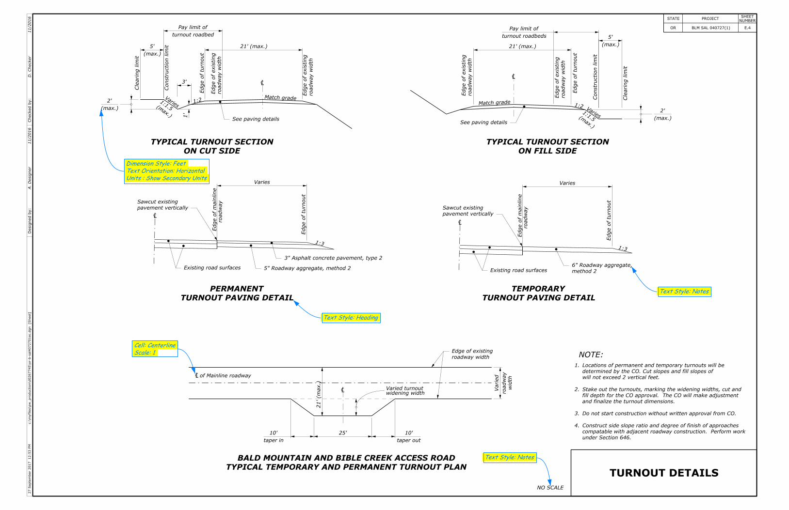
See paving details
CL
21' (max.)
road
way
width
Edge
ofexisting
road
way
width
Edge
ofexisting
turnout roadbed
Pay limit of
Edge
ofturnout
Constr
uctionli
mit
(max.)
5'
Cle
arin
gli
mit
Varies(max.)
2'
3'
1:2
(max.)
1:1.5
1'
Matchgrade
ON CUT SIDE
TYPICAL TURNOUT SECTION
See paving details
CL
21' (max.)
road
way
width
Edge
ofexisting
turnout roadbeds
Pay limit of
Edge
ofturnout
road
way
width
Edge
ofexisting
(max.)
5'
Cle
arin
gli
mit
Constr
uctionli
mit
Matchgrade 1:2 Varies(max.)
1:1.5
ON FILL SIDE
TYPICAL TURNOUT SECTION
(max.)
2'
CL
Varies
Edge
of
mainline
road
way
Edge
ofturnout
pavement vertically
Sawcut existing
Existing road surfaces
3" Asphalt concrete pavement, type 2
5" Roadway aggregate, method 2
1:3
TURNOUT PAVING DETAIL
PERMANENT
CL
Edge
ofturnout
road
way
Edge
of
mainline
pavement vertically
Sawcut existing
1:3
Varies
Existing road surfaces method 2
6" Roadway aggregate,
TURNOUT PAVING DETAIL
TEMPORARY
taper out
10'
25'
taper in
10'
of Mainline roadwayCL
CL
21'(m
ax.)
widening widthVaried turnout
roadway width
Edge of existing
road
way
Varie
d
width
TYPICAL TEMPORARY AND PERMANENT TURNOUT PLAN
BALD MOUNTAIN AND BIBLE CREEK ACCESS ROAD
NOTE:
TURNOUT DETAILS
4.
3.
2.
1.
NO SCALE
Text Style: Heading
Text Style: Notes
Text Style: Notes
Units : Show Secondary Units
Text Orientation: Horizontal
Dimension Style: Feet
Scale: 1
Cell: Centerline
under Section 646.
compatable with adjacent roadway construction. Perform work
Construct side slope ratio and degree of finish of approaches
Do not start construction without written approval from CO.
and finalize the turnout dimensions.
fill depth for the CO approval. The CO will make adjustment
Stake out the turnouts, marking the widening widths, cut and
will not exceed 2 vertical feet.
determined by the CO. Cut slopes and fill slopes of
Locations of permanent and temporary turnouts will be
]Sheet
[c:\m
yfiles\p
w_production\d0267745\or-b-sal4
072701ec.d
gn
12:53
PM
27
Septe
mber
2017
STATE PROJECTNUMBER
SHEET
E.4OR BLM SAL 040727(1) Checked
by:
Desig
ned
by:
A.
Desig
ner
D.
Checker
11/2016
11/2016
NOTE:
FOOTNOTE:
field conditions as approved by the CO.
alignment of new approach is at an angle. Adjust radii to meet
1. Continue approach radius as required if connection to existing
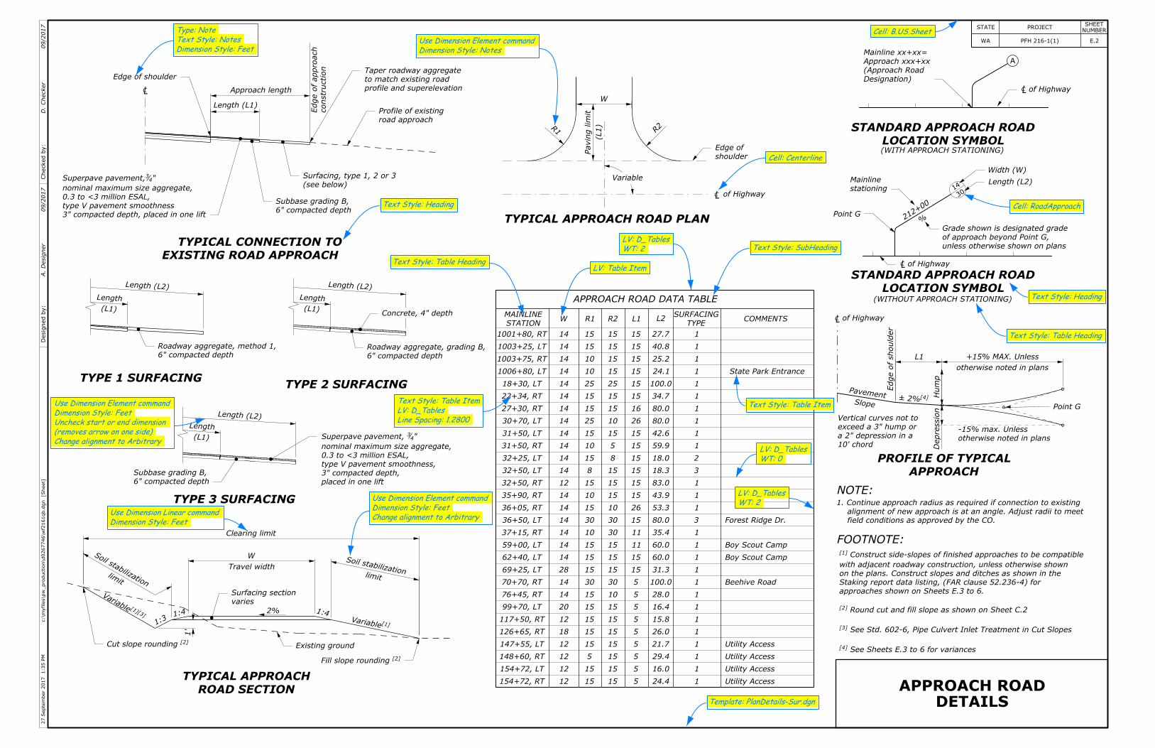
TYPICAL APPROACH ROAD PLAN
EXISTING ROAD APPROACH
TYPICAL CONNECTION TO
Length (L1)
Approach length
constr
uction
Edge
ofapproach
TYPE 1 SURFACINGTYPE 2 SURFACING
TYPE 3 SURFACING
LOCATION SYMBOL
STANDARD APPROACH ROAD
LOCATION SYMBOL
STANDARD APPROACH ROAD
APPROACH
PROFILE OF TYPICAL
of Highway
R1 R2 L1 L2TYPE
SURFACINGCOMMENTS
STATION
MAINLINEW
15
15
5
15
15
15
15
15
30
15
15
15
10
30
15
10
15
8
15
10
15
25
15
15
25
10
10
15
15
12
12
12
12
18
12
20
14
14
28
14
14
14
14
14
14
12
14
14
14
14
14
14
14
14
14
14
14
14
ROAD SECTION
TYPICAL APPROACH
(WITH APPROACH STATIONING)
of Highway
Edge
ofshould
er
otherwise noted in plans
-15% max. Unless
otherwise noted in plans
+15% MAX. Unless
L1
Travel width
W
[1]Variable
1'
10' chord
a 2" depression in a
exceed a 3" hump or
Vertical curves not to
[4]±2%
shoulder
Edge of
W
6" compacted depth
Subbase grading B,
(see below)
Surfacing, type 1, 2 or 3
Edge of shoulder
profile and superelevation
to match existing road
Taper roadway aggregate
road approach
Profile of existing
6" compacted depth
Subbase grading B,
6" compacted depth
Roadway aggregate, grading B,
6" compacted depth
Roadway aggregate, method 1,
Designation)
(Approach Road
Approach xxx+xx
Mainline xx+xx=
of Highway
Point G
stationing
Mainline
212+
00
%
unless otherwise shown on plans
of approach beyond Point G,
Grade shown is designated grade
Width (W)
Length (L2)
of Highway
Point G
PavementSlope
1:4
Existing ground
[2]Fill slope rounding
1:3
1:42%
varies
Surfacing section
limit
Soilstabilization
Length(L2)
(L1)
Length
Length(L2)
Length(L2)
(L1)
Length
(L1)
Length
Clearing limit
Hu
mp
Depressio
n
154+72, RT
154+72, LT
148+60, RT
147+55, LT
126+65, RT
117+50, RT
99+70, LT
76+45, RT
70+70, RT
69+25, LT
62+40, LT
59+00, LT
37+15, RT
36+50, LT
36+05, RT
35+90, RT
32+50, RT
32+50, LT
32+25, LT
31+50, RT
31+50, LT
30+70, LT
27+30, RT
22+34, RT
18+30, LT
1006+80, LT
1003+75, RT
1003+25, LT
1001+80, RT
[2]Cut slope rounding
3" compacted depth, placed in one lift
type V pavement smoothness
0.3 to <3 million ESAL,
nominal maximum size aggregate,
"43Superpave pavement,
[3]
[1]
Variable
See Sheets E.3 to 6 for variances[4]
See Std. 602-6, Pipe Culvert Inlet Treatment in Cut Slopes[3]
Round cut and fill slope as shown on Sheet C.2[2]
approaches shown on Sheets E.3 to 6.
Staking report data listing, (FAR clause 52.236-4) for
on the plans. Construct slopes and ditches as shown in the
with adjacent roadway construction, unless otherwise shown
Construct side-slopes of finished approaches to be compatible[1]
R2
Variable
R1
(L1)
Pavin
gli
mit
APPROACH ROAD DATA TABLE
limit
Soilstabilization
(WITHOUT APPROACH STATIONING)
15
15
15
15
15
15
15
10
30
15
15
15
30
30
10
15
15
15
8
5
15
10
15
15
25
15
15
15
15
5
5
5
5
5
5
5
5
5
15
15
11
11
15
26
15
15
15
15
15
15
26
16
15
15
15
15
15
15
24.4
16.0
29.4
21.7
26.0
15.8
16.4
28.0
100.0
31.3
60.0
60.0
35.4
80.0
53.3
43.9
83.0
18.3
18.0
59.9
42.6
80.0
80.0
34.7
100.0
24.1
25.2
40.8
27.7
1
1
1
1
1
1
1
1
1
1
1
1
1
3
1
1
1
3
2
1
1
1
1
1
1
1
1
1
1
State Park Entrance
Concrete, 4" depth
Utility Access
Utility Access
Utility Access
Utility Access
Beehive Road
Boy Scout Camp
Boy Scout Camp
Forest Ridge Dr.
placed in one lift
3" compacted depth,
type V pavement smoothness,
0.3 to <3 million ESAL,
nominal maximum size aggregate,
" 43Superpave pavement,
DETAILS
APPROACH ROAD
CL
CL CL
CL
CL
14
30
]Sheet
[c:\m
yfiles\p
w_production\d0267746\wf2
161qb.d
gn
1:35
PM
27
Septe
mber
2017
STATE PROJECTNUMBER
SHEET
2E.WA PFH 216-1(1) Checked
by:
Desig
ned
by:
A.
Desig
ner
D.
Checker
09/2017
09/2017
A
HeadingText Style:
Table HeadingText Style:
SubHeadingText Style:
CenterlineCell:
B.US.SheetCell:
Table HeadingText Style:
HeadingText Style:
NotesDimension Style:
Use Dimension Element command
Change alignment to Arbitrary
(removes arrow on one side)
Uncheck start or end dimension
FeetDimension Style:
Use Dimension Element command
Table ItemLV:
Change alignment to Arbitrary
FeetDimension Style:
Use Dimension Element command
FeetDimension Style:
Use Dimension Linear command
Template: PlanDetails-Sur.dgn
0WT:
D_TablesLV:
2WT:
D_TablesLV:
Table ItemText Style:
2WT:
D_TablesLV:
RoadApproachCell:
FeetDimension Style:
NotesText Style:
NoteType:
1.2800Line Spacing:
D_TablesLV:
Table ItemText Style:
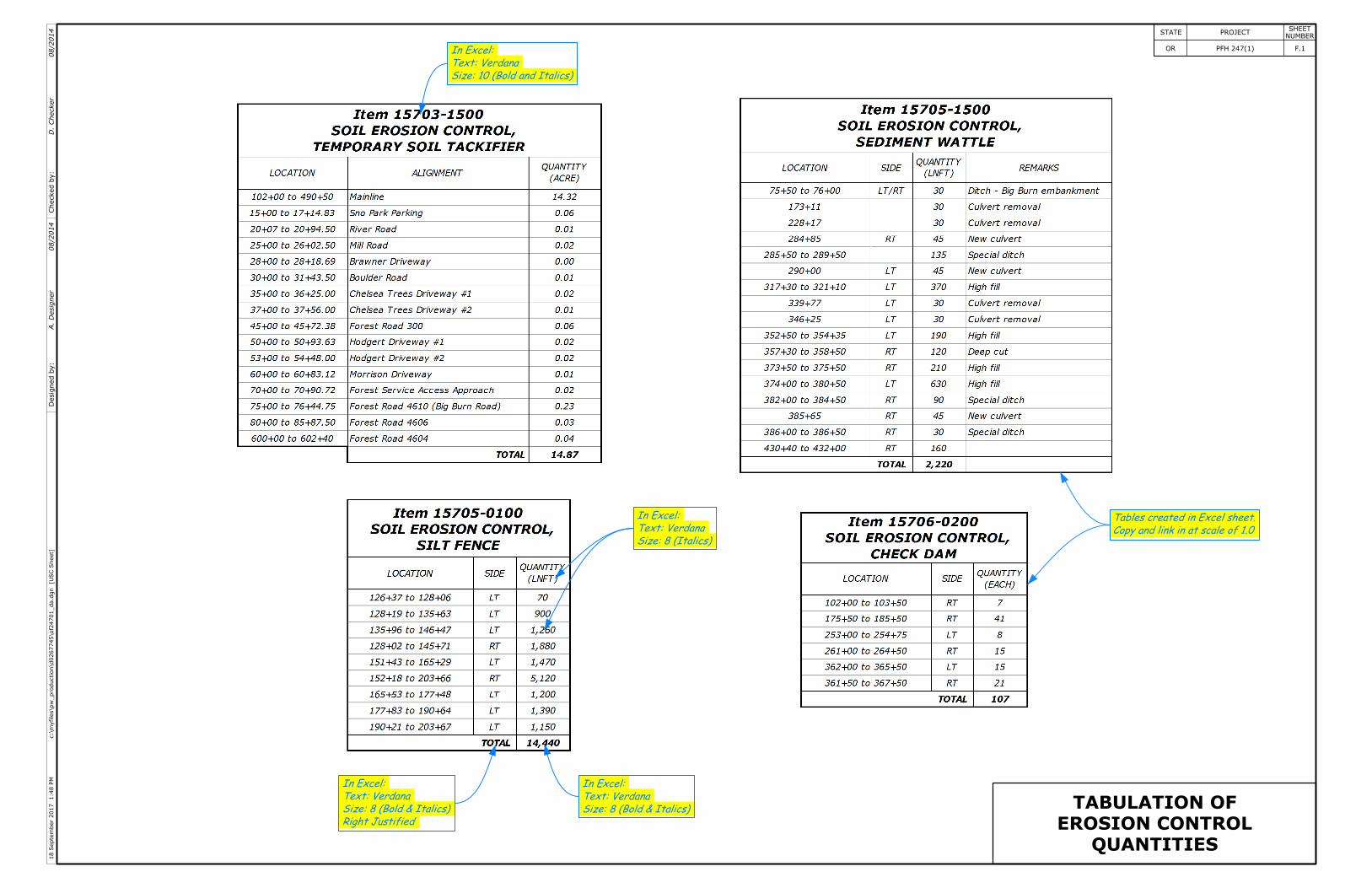
QUANTITIES
EROSION CONTROL
TABULATION OF
]U
SC
Sheet
[c:\m
yfiles\p
w_production\d0267745\of2
4701_da.d
gn
1:48
PM
18
Septe
mber
2017
STATE PROJECTNUMBER
SHEET
F.1OR PFH 247(1) Checked
by:
Desig
ned
by:
A.
Desig
ner
D.
Checker
08/2014
08/2014
Size: 10 (Bold and Italics)
Text: Verdana
In Excel:
Size: 8 (Italics)
Text: Verdana
In Excel:
Size: 8 (Bold & Italics)
Text: Verdana
In Excel:
Right Justified
Size: 8 (Bold & Italics)
Text: Verdana
In Excel:
Copy and link in at scale of 1.0
Tables created in Excel sheet.

110
PT
110+
38.4
7
PC
111+
21.1
2
115
PT
115+
47.2
1 120
125
105 P
T106+
58.0
3
PC
108+
49.4
4 110 P
T110+
38.4
7
N
N
PLANS
EROSION CONTROL
Text Style: Heading
Text Style: Note Heading
Dimension Style: Limits/Section
Text Style: Note
Text Style: Note Heading
scale: 1
Cell: North arrow
]U
SC
Sheet
[c:\m
yfiles\p
w_production\d0267745\of2
4701_db.d
gn
1:49
PM
18
Septe
mber
2017
STATE PROJECTNUMBER
SHEET
F.2OR PFH 247(1) Checked
by:
Desig
ned
by:
A.
Desig
ner
D.
Checker
08/2017
08/2017
Fiber rolls, typ.
Silt fence, typ.
BEGIN PROJECT
102+00.00
BEGIN RECONSTRUCTION
LEGEND:Check dam, typ.
Slope stake limits
Proposed edge of pavement
Slope stake limits
Proposed edge of pavement
See Sheet F.17 for details.
Install soil erosion control, fiber rolls, across ditch.
See Sheet F.17 for details.
Install soil erosion control, fiber rolls.
See Sheet F.17 for details.
Install soil erosion control, check dams.
See Sheet F.17 for details.
Install soil erosion control, silt fence.
4725
4730
4735
4740
4740
4745
4745
4750
4750
4750
4755
4745
4750
4755
4755
4755
4755
946
945+60
5 0 5 10 15 20
3485
3485
N
SCALE IN FEET
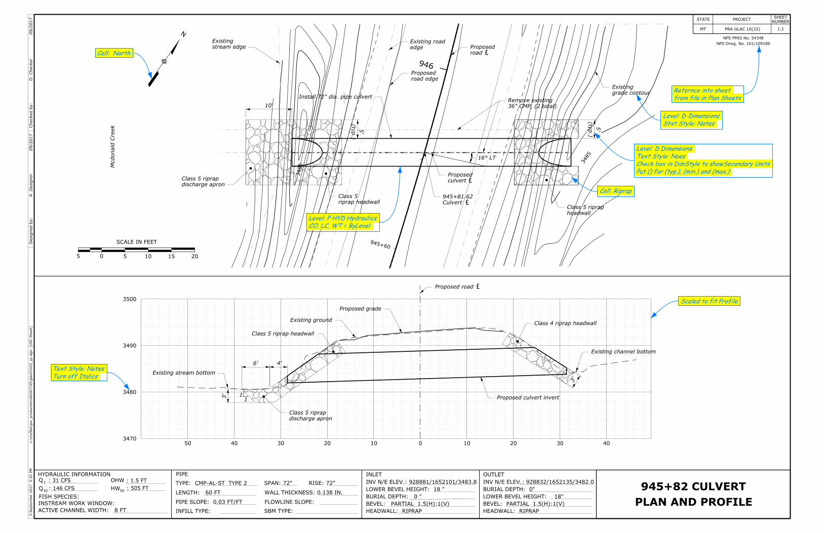
NPS Drwg. No. 101/109186
NPS PMIS No. 54348
PLAN AND PROFILE
945+82 CULVERT
HYDRAULIC INFORMATION PIPE
LENGTH: 60 FT
PIPE SLOPE: 0.03 FT/FT
INLET OUTLET
LOWER BEVEL HEIGHT: 18"
Q : 31 CFS2
Q50
OHW
50HW: 146 CFS
ACTIVE CHANNEL WIDTH: 8 FT
FISH SPECIES:
INSTREAM WORK WINDOW:
: 1.5 FT
: 505 FTTYPE: CMP-AL-ST TYPE 2
INFILL TYPE:
SPAN: 72"
WALL THICKNESS: 0.138 IN.
RISE: 72"
FLOWLINE SLOPE:
SBM TYPE:
INV N/E ELEV.: 928881/1652101/3483.8
LOWER BEVEL HEIGHT: 18 "
BURIAL DEPTH: 0 "
BEVEL: PARTIAL 1.5(H):1(V)
HEADWALL: RIPRAP
INV N/E ELEV.: 928832/1652135/3482.0
BURIAL DEPTH: 0"
BEVEL: PARTIAL 1.5(H):1(V)
HEADWALL: RIPRAP
3500
3490
3480
347050 40 30 20 10 0 10 20 30 40
11
4'6'
]U
SC
Sheet
[c:\m
yfiles\p
w_production\d0267745\gla
c01022_gc.d
gn
3:25
PM
5Septe
mber
2017
STATE PROJECTNUMBER
SHEET
I.3MT PRA GLAC 10(22) Checked
by:
Desig
ned
by:
A.
Desig
ner
D.
Checker
09/2017
09/2017
Mcdonald
Creek
LC
LC
LC
LC
(ty
p.)
5'
(ty
p.)
5'
10'
16° LT
3'
3'
from file in Plan Sheets
Refernce into sheet
Stxt Style: Notes
Level: D-Dimensions
Put () for (typ.), (min.) and (max.)
Check box in DimStyle to showSecondary Units
Text Style: Noes
Level: D Dimensions
Cell: Riprap
CO, LC, WT = ByLevel
Level: P HYD Hydraulics
Cell: North
Scaled to fit Profile
Turn off Italics
Text Style: NotesExisting stream bottom
Existing ground
Proposed road
Proposed grade
Class 4 riprap headwall
Existing channel bottom
Proposed culvert invert
discharge apron
Class 5 riprap
Class 5 riprap headwall
stream edge
Existing
Install 72" dia. pipe culvert
headwall
Class 5 riprapCulvert
945+81.62
culvert
Proposed
road edge
Proposed
edge
Existing road
road
Proposed
36" CMP, (2 total)
Remove existing
grade contour
Existing
riprap headwall
Class 5
discharge apron
Class 5 riprap
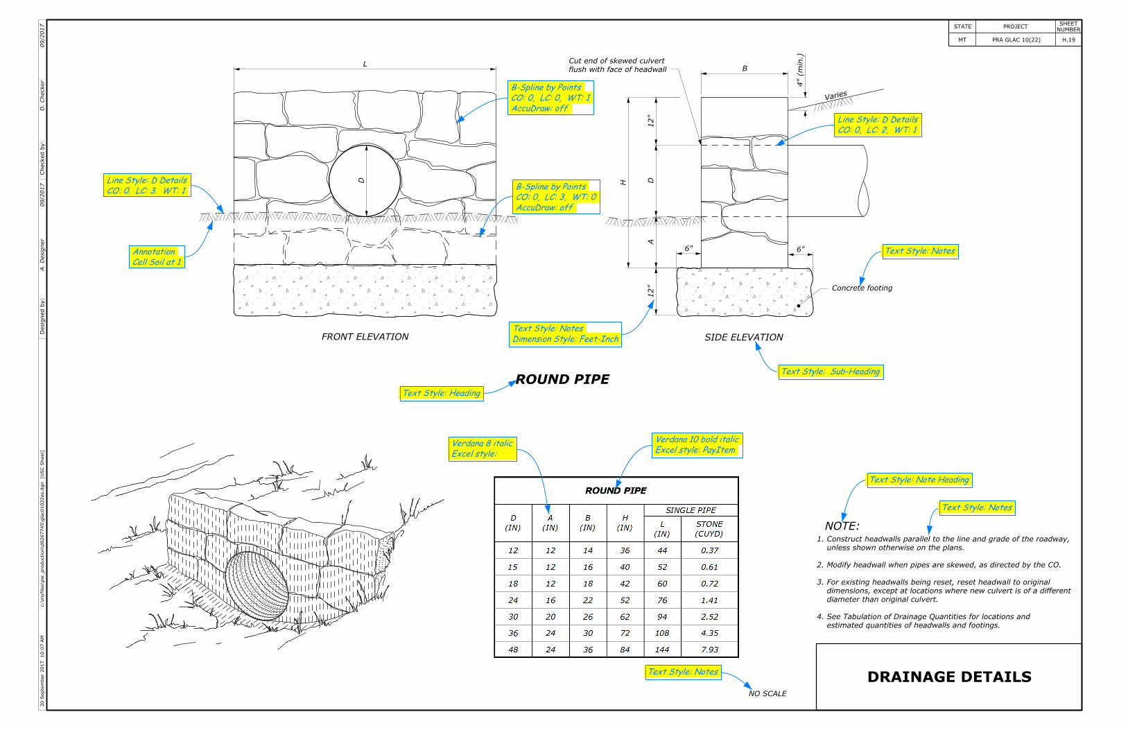
estimated quantities of headwalls and footings.
See Tabulation of Drainage Quantities for locations and
diameter than original culvert.
dimensions, except at locations where new culvert is of a different
For existing headwalls being reset, reset headwall to original
Modify headwall when pipes are skewed, as directed by the CO.
unless shown otherwise on the plans.
Construct headwalls parallel to the line and grade of the roadway,
4.
3.
2.
1.
DRAINAGE DETAILSNO SCALE
NOTE:
ROUND PIPE
FRONT ELEVATION SIDE ELEVATION
Concrete footing
L
D
4"(min.)
B
6" 6"
12"
DA
12"
H
flush with face of headwall
Cut end of skewed culvert
seiraV
Text Style: Sub-Heading
Text Style: Note Heading
Text Style: Notes
Excel style: PayItem
Verdana 10 bold italic
Excel style:
Verdana 8 italic
Text Style: Notes
Dimension Style: Feet-Inch
Text Style: Notes
Cell Soil at 1
Annotation
Text Style: Heading
CO: 0, LC: 2, WT: 1
Line Style: D Details
CO: 0. LC: 3. WT: 1
Line Style: D Details
AccuDraw: off
CO: 0, LC: 0, WT: 1
B-Spline by Points
AccuDraw: off
CO: 0, LC: 3, WT: 0
B-Spline by Points
Text Style: Notes
]U
SC
Sheet
[c:\m
yfiles\p
w_production\d0267745\gla
c01022es.d
gn
10:07
AM
20
Septe
mber
2017
STATE PROJECTNUMBER
SHEET
H.19MT PRA GLAC 10(22) Checked
by:
Desig
ned
by:
A.
Desig
ner
D.
Checker
09/2017
09/2017
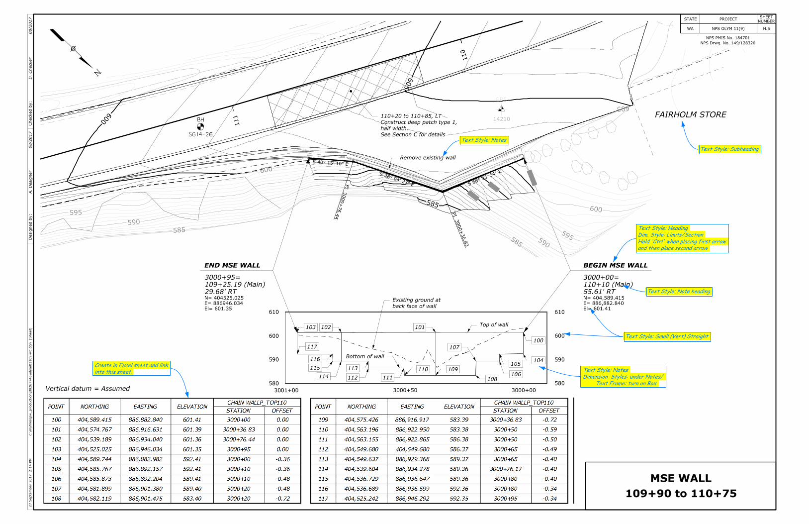
SG14-26
BH
110
580
590
600
610
580
590
600
610
3000+003000+503001+00
Top of wall
Bottom of wall
N
FAIRHOLM STORE
BEGIN MSE WALLEND MSE WALL
PI
3000+
36.8
3
PI
3000+
76.4
4
101102103
104105
106108
109110
111112
113
114
115
116
117
100
107
585
600
605
111
El= 601.35
E= 886946.034
N= 404525.025
El= 601.41
E= 886,882.840
N= 404,589.415
29.68' RT
109+25.19 (Main)
3000+95=
55.61' RT
110+10 (Main)
3000+00=
109+90 to 110+75
MSE WALL
610
600
590
580
3001+00 3000+50 3000+00
610
600
590
580
See Section C for details
half width.
Construct deep patch type 1,
110+20 to 110+85, LT
Text Style: Notes
Text Style: Subheading
and then place second arrow
Hold 'Ctrl' when placing first arrow
Dim. Style: Limits/Section
Text Style: Heading
Text Frame: turn on Box
Dimension Styles: under Notes/
Text Style: Notesinto this sheet.
Create in Excel sheet and link
back face of wall
Existing ground at
Remove existing wall
NPS Drwg. No. 149/128320
NPS PMIS No. 184701
Text Style: Small (Vert) Straight
]Sheet
[c:\m
yfiles\p
w_production\d0267746\oly
m01109-wc.d
gn
2:14
PM
27
Septe
mber
2017
STATE PROJECTNUMBER
SHEET
H.5WA NPS OLYM 11(9) Checked
by:
Desig
ned
by:
A.
Desig
ner
D.
Checker
08/2017
08/2017
Vertical datum = Assumed
Text Style: Note heading
GPS
14210
585
585590
590
595
595600
600
605
595590
3000
Scale in miles
0 181
41
21
ROAD WORK
END
ROAD
WORK
AHEAD
ROAD
WORK
AHEAD
ROAD
WORK
AHEAD
ROAD
WORK
AHEAD
ROAD WORK
END
SPEED
LIMIT
25
ROAD CLOSED
1 MILE AHEAD
ROAD CLOSED
ROAD WORK
END
ROAD CLOSED
MISSION RIDGE RD
MISSION RIDGE RD
EMERGENCY TRAVEL ONLY
APRIL 16 - OCT 31
EMERGENCY TRAVEL ONLY
APRIL 16 - OCT 31
APRIL 16 - OCT 31
EMERGENCY TRAVEL ONLY
USE EXTREMECAUTION
CYCLESMOTOR
CLOSED TO PUBLIC USE
MISSION RIDGE ROAD
MISSION RIDGE ROAD
MP 0 - MP 4
ROAD WORK
EXPECT DELAYS
CLOSED TO PUBLIC USE
MISSION RIDGE ROAD
ROAD
CLOSED
SPEED
LIMIT
25
ROAD
WORK
AHEAD
ROAD
CLOSED
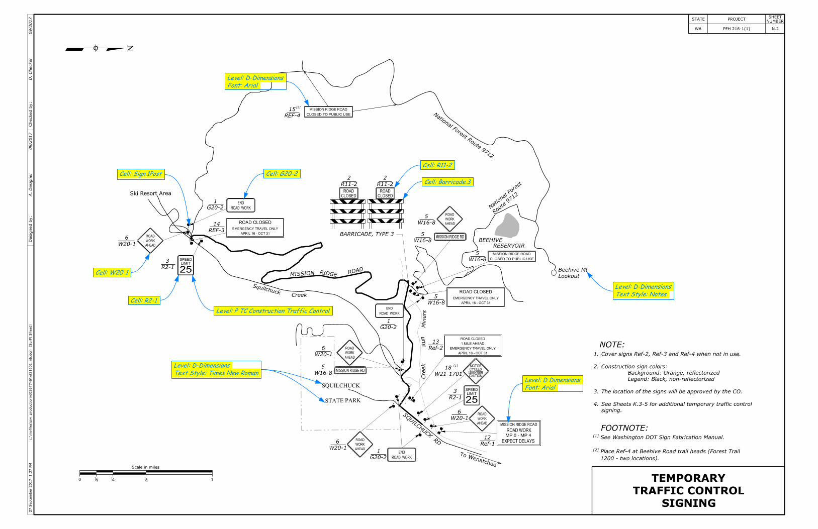
SIGNING
TRAFFIC CONTROL
TEMPORARY
Ski Resort Area
W20-1
6
R2-1
3
REF-3
14
G20-2
1
SquilchuckCreek
MISSION RIDGE ROAD
G20-2
1
W20-1
6
W16-8
5
SQUILCHUCK
STATEPARK
W20-1
6
G20-2
1
SQ
UILC
HUCK
RD
ToWenatchee
Route
9712
NationalF
orest
Lookout
Beehive Mt
BEEHIVE
RESERVOIR
W16-8
5
W16-8
5
W16-8
5
R11-2
2
W16-8
5
Ref-2
13
W21-1701
18
R2-1
3
W20-1
6
Ref-1
12
Min
ers
Run
Creek
NationalForest
Route
9712
NOTE:
FOOTNOTE:
4.
3.
2.
1.
1200 - two locations).
Place Ref-4 at Beehive Road trail heads (Forest Trail[2]
See Washington DOT Sign Fabrication Manual.[1]
N
BARRICADE, TYPE 3
R11-2
2
REF-4
15[2]
[1]
]SurFt
Sheet
[c:\m
yfiles\p
w_production\d0267746\wf2
1601_nb.d
gn
1:37
PM
27
Septe
mber
2017
STATE PROJECTNUMBER
SHEET
N.2WA PFH 216-1(1) Checked
by:
Desig
ned
by:
A.
Desig
ner
D.
Checker
09/2017
09/2017
signing.
See Sheets K.3-5 for additional temporary traffic control
The location of the signs will be approved by the CO.
Legend: Black, non-reflectorized
Background: Orange, reflectorized
Construction sign colors:
Cover signs Ref-2, Ref-3 and Ref-4 when not in use.
Cell: Sign.1Post Cell: G20-2
Text Style: Times New Roman
Level: D-Dimensions
Level: P TC Construction Traffic Control
Cell: R2-1
Cell: W20-1
Font: Arial
Level: D-Dimensions
Cell: R11-2
Text Style: Notes
Level: D-Dimensions
Font: Arial
Level: D Dimensions
Cell: Barricade.3
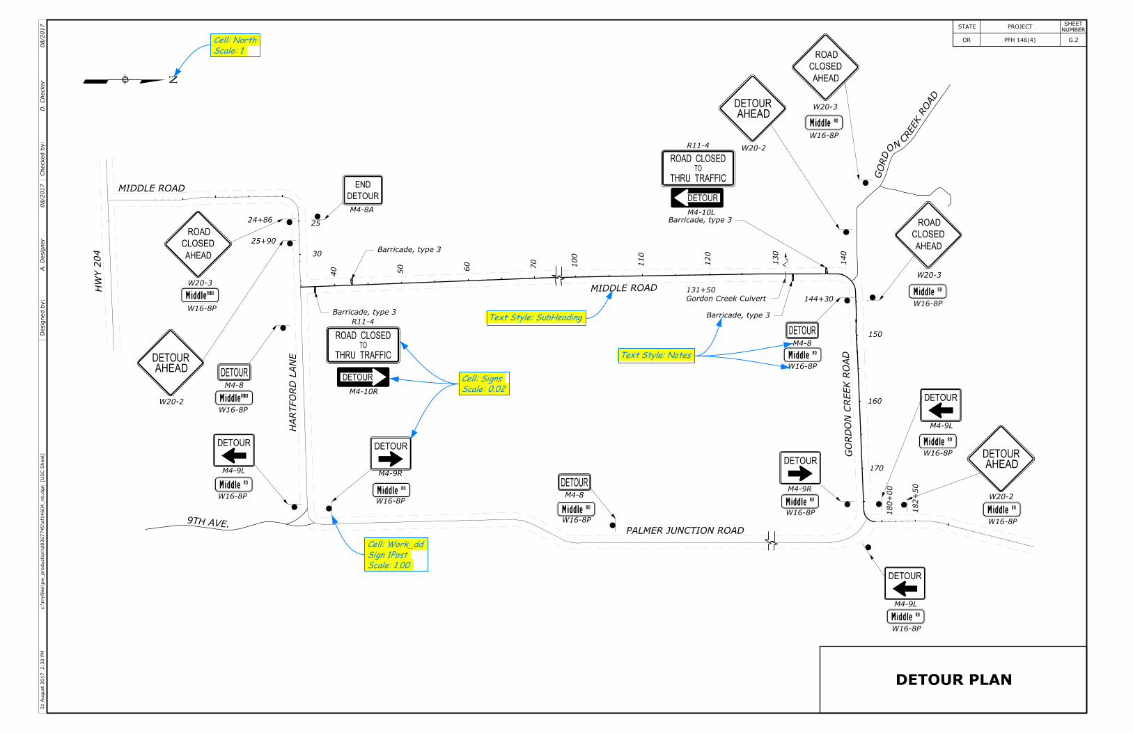
DETOUR PLAN
ROAD CLOSEDTO
THRU TRAFFIC
ROAD CLOSEDTO
THRU TRAFFIC
CLOSED
ROAD
AHEAD
AHEADDETOUR
DETOUR
DETOUR DETOUR
DETOUR
END
DETOUR DETOUR
CLOSED
ROAD
AHEAD
AHEADDETOUR
CLOSED
ROAD
AHEAD
DETOUR
AHEADDETOUR
DETOUR
DETOUR
DETOUR
DETOUR
PALMER JUNCTION ROAD
MIDDLEROAD
MIDDLE ROAD
HA
RTF
OR
DL
AN
E
GO
RD
ON
CR
EE
KR
OA
D
9THAVE.
HW
Y204
DA
OR
KE
ER
CN
O
DR
OG
W20-3
W16-8P
W20-2
W20-2
W20-2
W20-3
W16-8P
W20-3
W16-8P
W16-8P
W16-8P
W16-8P
W16-8P
W16-8P
W16-8PW16-8P
W16-8P
M4-9L
M4-9L M4-9R
M4-9R
M4-9L
W16-8P
M4-8
M4-8
M4-8A
R11-4
M4-10R
R11-4
M4-10L
M4-8
Gordon Creek Culvert
131+50
24+86
25+90
144+30
180+
00
182+
50
140
130
120
110
100
Text Style: Notes
Text Style: SubHeading
Scale: 0.02
Cell: Signs
N
Scale: 1
Cell: North
Scale: 1.00
Sign 1Post
Cell: Work_dd
]U
SC
Sheet
[c:\m
yfiles\p
w_production\d0267745\of1
4604_nb.d
gn
2:30
PM
31
August
2017
STATE PROJECTNUMBER
SHEET
G.2OR PFH 146(4) Checked
by:
Desig
ned
by:
A.
Desig
ner
D.
Checker
08/2017
08/2017
Barricade, type 3
Barricade, type 3
Barricade, type 3
Barricade, type 3
40 50 60 70
150
160
170
30
25
NOTE:
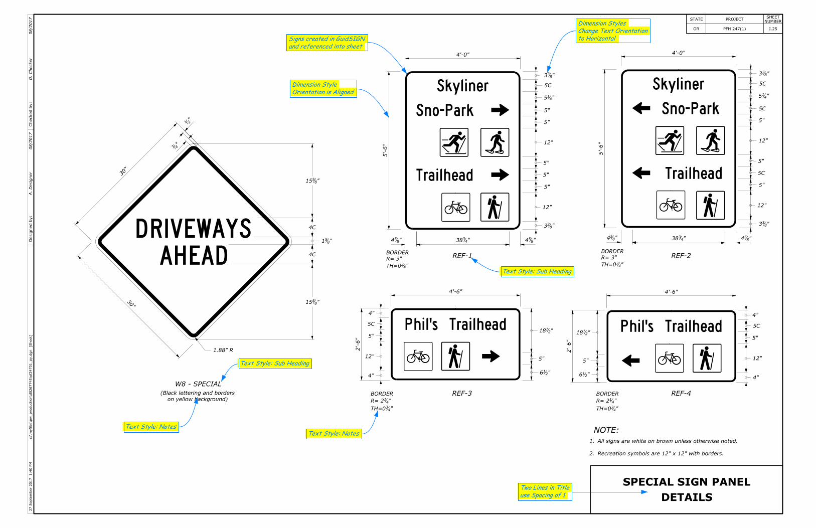
DETAILS
SPECIAL SIGN PANEL
Recreation symbols are 12" x 12" with borders.
All signs are white on brown unless otherwise noted.
2.
1.
4'-0"
5'-6"
"854 "8
54"4338"8
54 "854"4
338
4'-0"
5'-6"
4'-6"
2'-6"
2'-6"
4'-6"
"833
5C
"415
5C
5"
12"
5"
5C
5"
12"
"833
"833
5C
"415
5"
5"
12"
5"
5"
5"
12"
"833
"216
5"
"2118
4"
12"
5"
5C
4"
4"
12"
5"
5C
4"
"216
5"
"2118
30"
30"
"21
"43
REF-1 REF-2
REF-3 REF-4
"43TH=0
R= 3"
BORDER
"43TH=0
R= 3"
BORDER
"43TH=0
"41R= 2
BORDER
"43TH=0
"41R= 2
BORDER
W8 - SPECIAL
on yellow background)
(Black lettering and borders
1.88" R
"8515
4C
"851
4C
"8515
and referenced into sheet
Signs created in GuidSIGN to Horizontal
Change Text Orientation
Dimension Styles
Orientation is Aligned
Dimension Style
Text Style: Sub Heading
Text Style: Notes
use Spacing of 1
Two Lines in Title
Text Style: Notes
Text Style: Sub Heading
]Sheet
[c:\m
yfiles\p
w_production\d0267745\of2
4701_py.d
gn
1:40
PM
27
Septe
mber
2017
STATE PROJECTNUMBER
SHEET
I.25OR PFH 247(1) Checked
by:
Desig
ned
by:
A.
Desig
ner
D.
Checker
08/2017
08/2017
25
MPH
25
MPH
105
110
110
115
120
125
Dimension Style: Limits/Section
Checked
by:
Desig
ned
by:
A.
Desig
ner
D.
Checker
08/2017
08/2017
N
Text Style: Note Heading
Text Style: Heading
102+00.00
BIKE LANE
ENDS
BIKE LANE
Install sign system R3-17
type B, solid double yellow centerline
Apply pavement markings,
sign system
Remove and reset
See Sheet I.22 for Detail
white bycycle symbol, (typ.)
Apply pavement markings, type B,
Install sign system R3-17
reset sign system
Remove and
to remain in place
Science School"
"Cascade
Existing sign
reset sign system
Remove and
edge of pavement
Proposed
edge line, 8" width
type B, solid white
Apply pavement markings,
N
BIKE LANE
BIKE LANE
See Sheet I.22 for Details
symbols, type B, bicycle.
Apply pavement markings,
reset sign system
Remove and
Proosed edge of pavement
type B, solid double yellow centerline
Apply pavement markings,
Install sign system R3-17
Install sign system REF-1
to remain in place
Existing signs
Install sign system REF-2
sign system
Remove and reset
See Sheet I.22 for details
symbols, type B, bicycle.
Apply pavement markings,
Install sign system R3-17
edge line, 4" width
type B, solid white
Apply pavement markings
solid white edge line 8" width
Apply pavement markings, type B,
sign system
Remove and reset
Remove sign system
See Sheet I.21 for details
"25 MPH" word message.
symbols type B white,
Apply pavement markings,
sign system
Remove and reset
17
16
15
CO: 4, LC: byLevel (0), WT: 1
Level: P TC Markings Pavement
CO: 4, LC: byLevel (0), WT: 2
Level: P TC Markings Pavement
Text Style: Notes
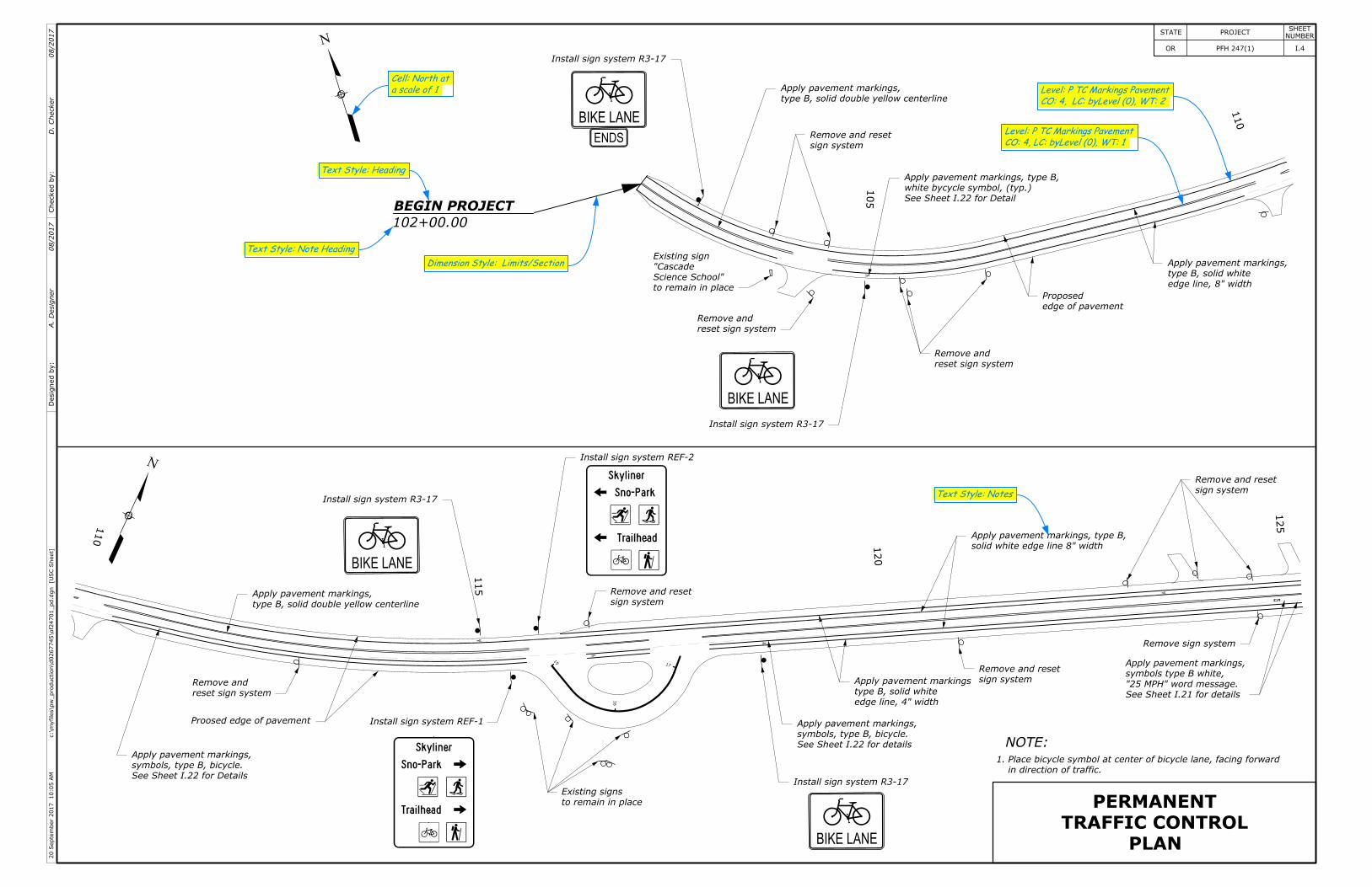
PLAN
TRAFFIC CONTROL
PERMANENT
in direction of traffic.
Place bicycle symbol at center of bicycle lane, facing forward1.
NOTE:
]U
SC
Sheet
[c:\m
yfiles\p
w_production\d0267745\of2
4701_pd.d
gn
10:05
AM
20
Septe
mber
2017
STATE PROJECTNUMBER
SHEET
I.4OR PFH 247(1)
a scale of 1
Cell: North at
BEGIN PROJECT
25 MPH 25 MPH 125
130
135
140
20 25
26
140
145
150
155
30
31
Checked
by:
Desig
ned
by:
A.
Desig
ner
D.
Checker
08/2017
08/2017
Text Style: Notes
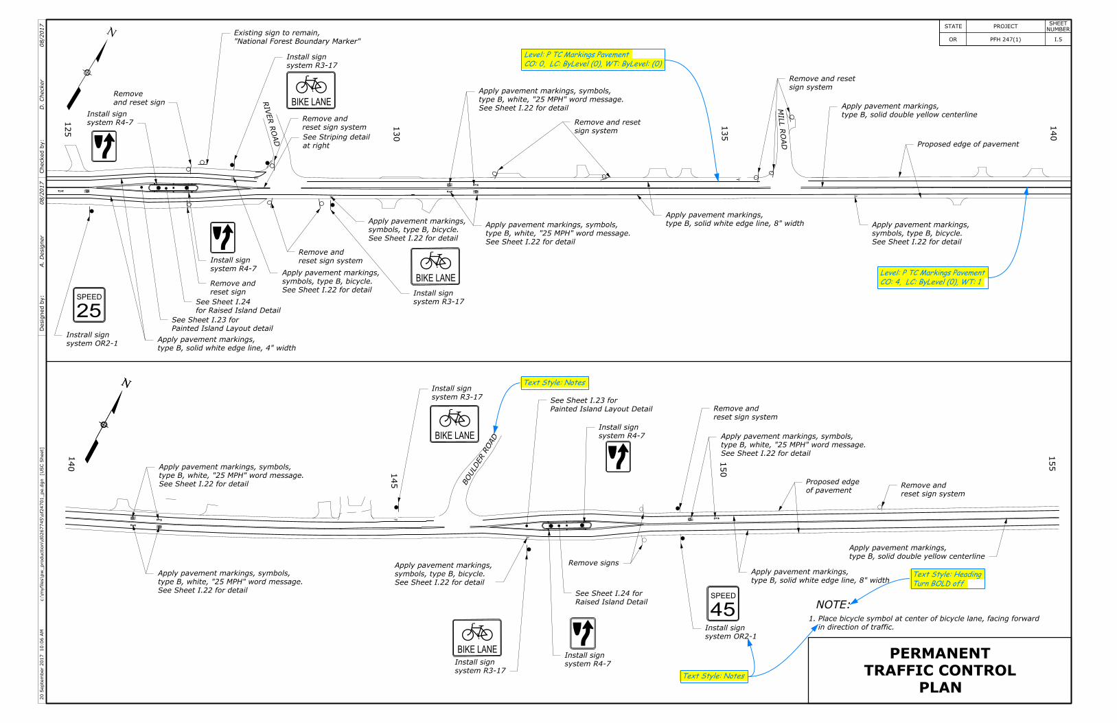
SPEED
45
SPEED
25
system OR2-1
Instrall sign
system R4-7
Install sign
"National Forest Boundary Marker"
Existing sign to remain,
system R3-17
Install sign
system R3-17
Install sign
BIKE LANE
BIKE LANERIV
ER
RO
AD
reset sign system
Remove and
system R4-7
Install sign reset sign system
Remove and
and reset sign
Remove
See Sheet I.22 for detail
symbols, type B, bicycle.
Apply pavement markings,
for Raised Island Detail
See Sheet I.24
Painted Island Layout detail
See Sheet I.23 for
reset sign
Remove and
type B, solid white edge line, 4" width
Apply pavement markings,
N
at right
See Striping detail
See Sheet I.22 for detail
symbols, type B, bicycle.
Apply pavement markings,
sign system
Remove and reset
See Sheet I.22 for detail
type B, white, "25 MPH" word message.
Apply pavement markings, symbols,
See Sheet I.22 for detail
type B, white, "25 MPH" word message.
Apply pavement markings, symbols, type B, solid white edge line, 8" width
Apply pavement markings,
MILL
RO
AD
sign system
Remove and reset
type B, solid double yellow centerline
Apply pavement markings,
Proposed edge of pavement
See Sheet I.22 for detail
symbols, type B, bicycle.
Apply pavement markings,
See Sheet I.22 for detail
type B, white, "25 MPH" word message.
Apply pavement markings, symbols,
See Sheet I.22 for detail
type B, white, "25 MPH" word message.
Apply pavement markings, symbols,
See Sheet I.22 for detail
type B, white, "25 MPH" word message.
Apply pavement markings, symbols,BIKE LANE
BIKE LANE
system R3-17
Install sign
system R3-17
Install sign
See Sheet I.22 for detail
symbols, type B, bicycle.
Apply pavement markings,
BO
ULD
ER
RO
AD system R4-7
Install sign
system R4-7
Install sign
Raised Island Detail
See Sheet I.24 for
Painted Island Layout Detail
See Sheet I.23 for
Remove signs
system OR2-1
Install sign
reset sign system
Remove and
reset sign system
Remove and
type B, solid white edge line, 8" width
Apply pavement markings,
of pavement
Proposed edge
type B, solid double yellow centerline
Apply pavement markings,
PLAN
TRAFFIC CONTROL
PERMANENT
in direction of traffic.
Place bicycle symbol at center of bicycle lane, facing forward1.
NOTE:
CO: 0, LC: ByLevel (0), WT: ByLevel: (0)
Level: P TC Markings Pavement
CO: 4, LC: ByLevel (0), WT: 1
Level: P TC Markings Pavement
Turn BOLD off
Text Style: Heading
Text Style: Notes
NN
]U
SC
Sheet
[c:\m
yfiles\p
w_production\d0267745\of2
4701_pe.d
gn
10:06
AM
20
Septe
mber
2017
STATE PROJECTNUMBER
SHEET
I.5OR PFH 247(1)