Embed Size (px)
Citation preview
IEEE TRANSACTIONS ON INSTRUMENTATION AND MEASUREMENT, VOL. IM-26, NO. 3, SEPTEMBER 1977
Misalignment of Coaxial Conductors
MICHAEL. P. PERRY, MEMBER, IEEE, AND LEROY B. MAJOR
Abstract-Compressed gas insulated coaxial transmission linesare being developed which withstand 1200-kV rms phase-to-phasevoltage and carry 3000 A continuous current. As a method of in-strumenting the voltage on a single-phase of coaxial line, an isolatedcapacitive section approximately one meter in length is insertedbetween the conductors. The resulting displacement current dueto line voltage is detected with low voltage electronics. In thepresent work, misalignment of the coaxial conductors is investi-gated theoretically and experimentally to determine the effect ofsmall relative displacements on the amount of capacitance of theisolated section. Capacitance change due only to conductor mis-alignment is found not to restrict severely the metering accuracyof the isolated section, provided reasonable tolerances for the po-sition of the isolated section are maintained. Forces due to imbal-ance of surface charge when the conductors are slightly misalignedare calculated and shown to be small, suggesting that a "voltagecoefficient" of capacitance also should not severely restrict themetering accuracy of the isolated section.
I. INTRODUCTIONTHE USE of compressed gas as an insulatingX medium has received renewed attention as an alter-
native method of power transmission between substations.At the present time, gas insulated coaxial transmissionlines are available which withstand 500-kV phase-to-phase.In addition, coaxial lines are presently being developedwhich allow 1200-kV rms voltage. The possible advantagesof this type of transmission include reduced space re-quirements for high-density areas as well as undergrounduse to reduce visibility. As in any power transmissionsystem, gas insulated systems must be instrumented forfault detection and accurate metering of power transferand consumption. Consequently, complete current andvoltage instrumentation systems and associated terminalequipment are being designed for metering and relaying,as well as carrier current injection and detection for a1200-kV ac compressed gas insulated coaxial transmissionline.The voltage measurement method suggested is shown
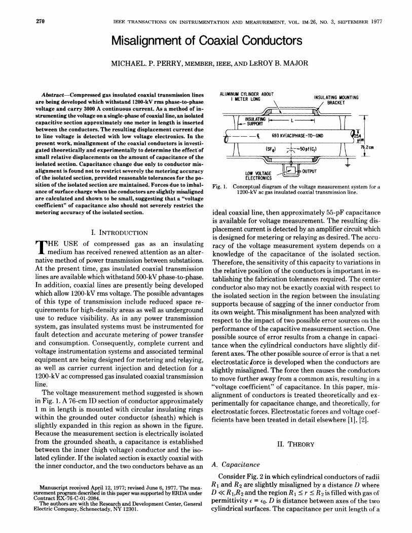
in Fig. 1. A 76-cm ID section of conductor approximately1 m in length is mounted with circular insulating ringswithin the grounded outer conductor (sheath) which isslightly expanded in this region as shown in the figure.Because the measurement section is electrically isolatedfrom the grounded sheath, a capacitance is establishedbetween the inner (high voltage) conductor and the iso-lated cylinder. If the isolated section is exactly coaxial withthe inner conductor, and the two conductors behave as an
Manuscript received April 12, 1977; revised June 6, 1977. The mea-surement program described in this paper was supported by ERDA underContract EX-76-C-01-2084.The authors are with the Research and Development Center, General
Electric Company, Schenectady, NY 12301.
ALUMINUM CYLINDER ABOUTMETER LONG
76.2cmI -
LOW VOLTAGE 4tuuOUruTELECTRONICS
Fig. 1. Conceptual diagram of the voltage measurement system for a1200-kV ac gas insulated coaxial transmission line.
ideal coaxial line, then approximately 55-pF capacitanceis available for voltage measurement. The resulting dis-placement current is detected by an amplifier circuit whichis designed for metering or relaying as desired. The accu-racy of the voltage measurement system depends on aknowledge of the capacitance of the isolated section.Therefore, the sensitivity of this capacity to variations inthe relative position of the conductors is important in es-tablishing the fabrication tolerances required. The centerconductor also may not be exactly coaxial with respect tothe isolated section in the region between the insulatingsupports because of sagging of the inner conductor fromits own weight. This misalignment has been analyzed withrespect to the impact of two possible error sources oIn theperformance of the capacitive measurement section. Onepossible source of error results from a change in capaci-tance when the cylindrical conductors have slightly dif-ferent axes. The other possible source of error is that a netelectrostatic force is developed when the conductors areslightly misaligned. The force then causes the conductorsto move further away from a common axis, resulting in a"voltage coefficient" of capacitance. In this paper, mis-alignment of conductors is treated theoretically and ex-perimentally for capacitance change, and theoretically, forelectrostatic forces. Electrostatic forces and voltage coef-ficients have been treated in detail elsewhere [1], [2].
II. THEORY
A. CapacitanceConsider Fig. 2 in which cylindrical conductors of radii
R1 and R2 are slightly misaligned by a distance D whereD << R1,R2 and the region R1 < r < R2 is filled with gas ofpermittivity e = ED. D is distance between axes of the twocylindrical surfaces. The capacitance per unit length of a
270
PERRY AND MAJOR: MISALIGNMENT5 OF COAXIAL CONDUCTORS
Fig. 2. Exaggerated end view of two cylindrical conductors with slightlymisaligned axes.
two conductor system in which one surface encloses theother is [3]
C = 2ird/(cosh-1 ml - cosh- iM2)
where
ml = (R12 - R22 + 1)/2R1D
and
M2= (R12-R22 - 1)/2R2D
(F/in) (1)
(2) jfi
(3)
e is the dielectic permittivity of the medium between theconductors. If D = 0, the familiar result is obtained forcoaxial cylinders:
366 cm
I ~ ~~~~~~~I-OOcm 33cni(1D)- /I~~~10'
- Do I)Q>/ 12.7cm(0D)
=z= ~~~~~~~~BU$4ING
| ~~~~~~~~~REGUlAED
IMZETAL CAGE
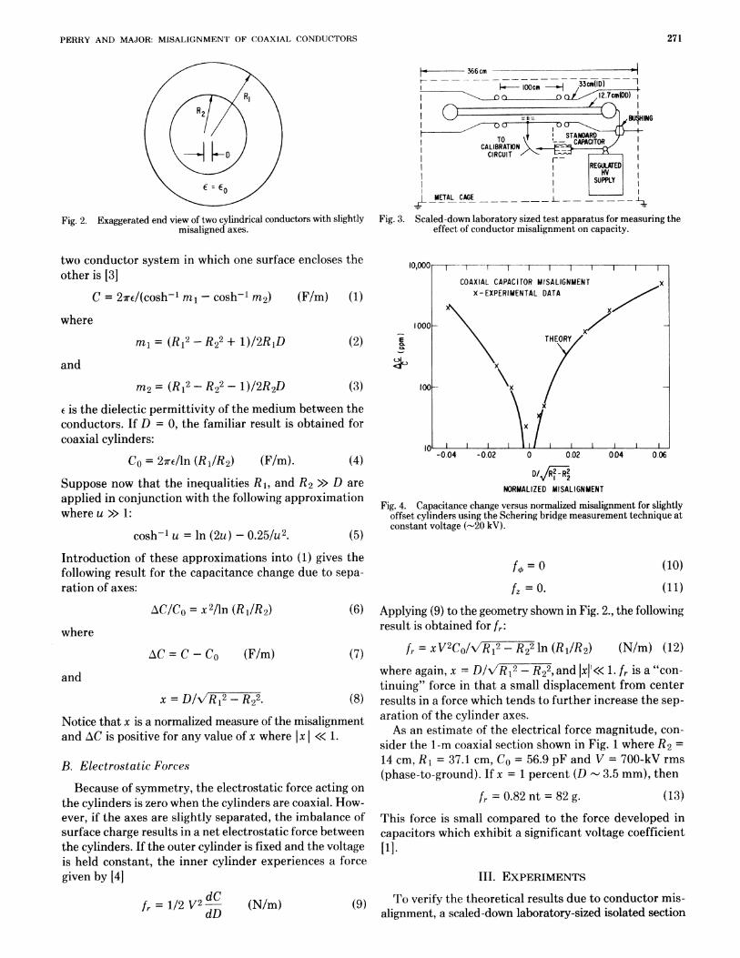
Fig. 3. Scaled-down laboratory sized test apparatus for measuring theeffect of conductor misalignment on capacity.
Co = 27rE/ln (R1/R2) (F/m). (4)Suppose now that the inequalities Rl, and H2 >> D areapplied in conjunction with the following approximationwhere u >> 1:
cosh-1 u = ln (2u) - 0.25/u2. (5)Introduction of these approximations into (1) gives thefollowing result for the capacitance change due to sepa-ration of axes:
-0 04 -0.02 0 0.02 004 0.06
0/. I2-R212NORMALIZED MISALIGNMENT
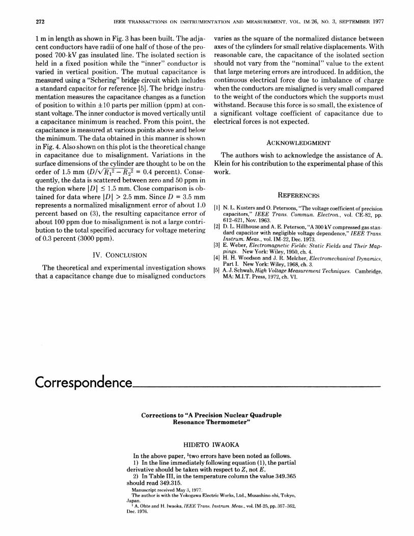
Fig. 4. Capacitance change versus normalized misalignment for slightlyoffset cylinders using the Schering bridge measurement technique atconstant voltage (-20 kV).
fo = 0
fz = 0.
(10)
(11)
AC/Co = x2/ln (R1/R2)
where
AC = C - CO (F/m)
(6)
(7)and
x= D/NR'12-HR22. (8)
Notice that x is a normalized measure of the misalignmentand AC is positive for any value of x where x «<< 1.
B. Electrostatic Forces
Because of symmetry, the electrostatic force acting onthe cylinders is zero when the cylinders are coaxial. How-ever, if the axes are slightly separated, the imbalance ofsurface charge results in a net electrostatic force betweenthe cylinders. If the outer cylinder is fixed and the voltageis held constant, the inner cylinder experiences a forcegiven by [4]
Applying (9) to the geometry shown in Fig. 2., the followingresult is obtained for fr:
/r =XV2C/R2-R22 In (Rj/R2) (N/m) (12)where again, x = D/`/R12 - R22, and IxlI<< 1. fr is a "con-tinuing" force in that a small displacement from centerresults in a force which tends to further increase the sep-aration of the cylinder axes.As an estimate of the electrical force magnitude, con-
sider the 1-m coaxial section shown in Fig. 1 where R2 =
14 cm, RH = 37.1 cm, Co = 56.9 pF and V = 700-kV rms(phase-to-ground). If x = 1 percent (D - 3.5 mm), then
fr = 0.82 nt = 82 g. (13)This force is small compared to the force developed incapacitors which exhibit a significant voltage coefficient1].
III. EXPERIMENTS
fr = 1/2 V2 dC (N/m) To verify the theoretical results due to conductor mis-alignment, a scaled-down laboratory-sized isolated section
271
IEEE TRANSACTIONS ON INSTRIUMENTATION AND MEASUREMENT, VOL. IM-26, NO. 3, SEPTEMBER 1977
1 m in length as shown in Fig. 3 has been built. The adja-cent conductors have radii of one half of those of the pro-
posed 700-kV gas insulated line. The isolated section isheld in a fixed position while the "inner" conductor isvaried in vertical position. The mutual capacitance ismeasured using a "Schering" bridge circuit which includesa standard capacitor for reference [5]. The bridge instru-mentation measures the capacitance changes as a functionof position to within ±10 parts per million (ppm) at con-
stant voltage. The inner conductor is moved vertically untila capacitance minimum is reached. From this point, thecapacitance is measured at various points above and belowthe minimum. The data obtained in this manner is shownin Fig. 4. Also shown on this plot is the theoretical changein capacitance due to misalignment. Variations in thesurface dimensions of the cylinder are thought to be on theorder of 1.5 mm (D R/R2 = 0.4 percent). Conse-quently, the data is scattered between zero and 50 ppm inthe region where IDI < 1.5 mm. Close comparison is ob-tained for data where IDI > 2.5 mm. Since D = 3.5 mmrepresents a normalized misalignment error of about 1.0percent based on (3), the resulting capacitance error ofabout 100 ppm due to misalignment is not a large contri-bution to the total specified accuracy for voltage meteringof 0.3 percent (3000 ppm).
IV. CONCLUSION
The theoretical and experimental investigation showsthat a capacitance change due to misaligned conductors
varies as the square of the normalized distance betweenaxes of the cylinders for small relative displacements. Withreasonable care, the capacitance of the isolated sectionshould not vary from the "nominal" value to the extentthat large metering errors are introduced. In addition, thecontinuous electrical force due to imbalance of chargewhen the conductors are misaligned is very small comparedto the weight of the conductors which the supports mustwithstand. Because this force is so small, the existence ofa significant voltage coefficient of capacitance due toelectrical forces is not expected.
ACKNOWLEDGMENT
The authors wish to acknowledge the assistance of A.Klein for his contribution to the experimental phase of thiswork.
REFERENCES
[1] N. L. Kusters and 0. Petersons, "The voltage coefficient of precisioncapacitors," IEEE Trans. Commun. Electron., vol. CE-82, pp.
612-621, Nov. 1963.[2] D. L. Hillhouse and A. E. Peterson, "A 300 kV compressed gas stan-
dard capacitor with negligible voltage dependence," IEEE Tran.s.Instrum. Meas., vol. IM-22, Dec. 1973.
[3] E. Weber, Electromagnetic Fields: Static Fields and Their Map-ptngs. New York: Wiley, 1950, ch. 4.
[4] H. H. Woodson and J. R. Melcher, Electromechanical Dynamics,Part I. New York: Wiley, 1968, ch. 3.
[51 A. J. Schwab, High Voltage Measurement Techniques. Cambridge,MA: M.I.T. Press, 1972, ch. VI.
Correspondence
Corrections to "A Precision Nuclear QuadrupleResonance Thermometer"
HIDETO IWAOKA
In the above paper, 'two errors have been noted as follows.1) In the line immediately following equation (1), the partial
derivative should be taken with respect to Z, not E.2) In Table III, in the temperature column the value 349.365
should read 349.315.Manuscript received May 3, 1977.The author is with the Yokogawa Electric Works, Ltd., Musashino-shi, Tokyo,
,Japan.1 A. Ohte and H. lwaoka, IEEE Trans. Instrum. Meas., vol. IM-25, pp. 357-362,
Dec. 1976.
272