Embed Size (px)
Citation preview

Mirsaeidi, Sohrab and Dong, Xinzhou and Tzelepis, Dimitrios and Mat
Said, Dalila and Dysko, Adam and Booth, Campbell (2018) A predictive
control strategy for mitigation of commutation failure in LCC-based
HVDC systems. IEEE Transactions on Power Electronics. ISSN 0885-
8993 (In Press) , http://dx.doi.org/10.1109/TPEL.2018.2820152
This version is available at https://strathprints.strath.ac.uk/63709/
Strathprints is designed to allow users to access the research output of the University of
Strathclyde. Unless otherwise explicitly stated on the manuscript, Copyright © and Moral Rights
for the papers on this site are retained by the individual authors and/or other copyright owners.
Please check the manuscript for details of any other licences that may have been applied. You
may not engage in further distribution of the material for any profitmaking activities or any
commercial gain. You may freely distribute both the url (https://strathprints.strath.ac.uk/) and the
content of this paper for research or private study, educational, or not-for-profit purposes without
prior permission or charge.
Any correspondence concerning this service should be sent to the Strathprints administrator:
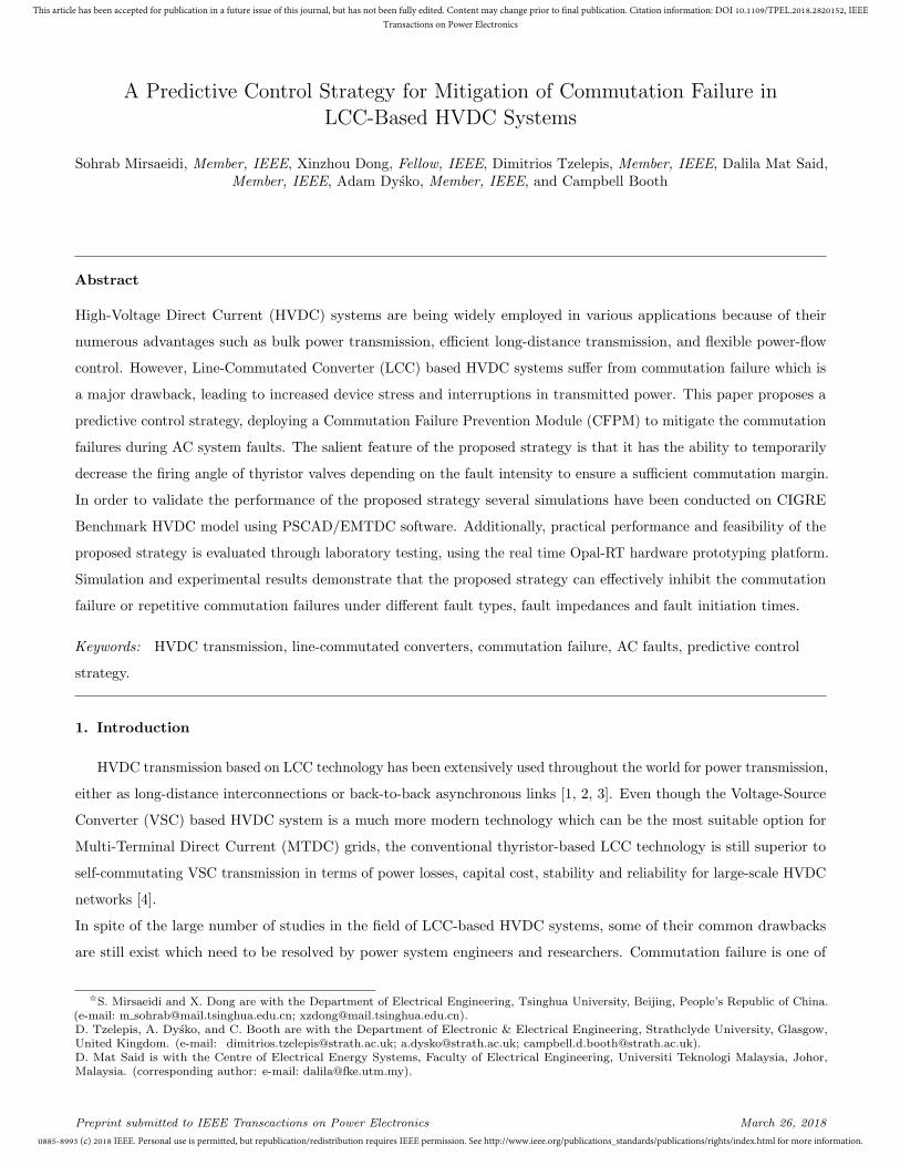
The Strathprints institutional repository (https://strathprints.strath.ac.uk) is a digital archive of University of Strathclyde research
outputs. It has been developed to disseminate open access research outputs, expose data about those outputs, and enable the
management and persistent access to Strathclyde's intellectual output.
0885-8993 (c) 2018 IEEE. Personal use is permitted, but republication/redistribution requires IEEE permission. See http://www.ieee.org/publications_standards/publications/rights/index.html for more information.
This article has been accepted for publication in a future issue of this journal, but has not been fully edited. Content may change prior to final publication. Citation information: DOI 10.1109/TPEL.2018.2820152, IEEE
Transactions on Power Electronics
A Predictive Control Strategy for Mitigation of Commutation Failure in
LCC-Based HVDC Systems
Sohrab Mirsaeidi, Member, IEEE, Xinzhou Dong, Fellow, IEEE, Dimitrios Tzelepis, Member, IEEE, Dalila Mat Said,Member, IEEE, Adam Dysko, Member, IEEE, and Campbell Booth
Abstract
High-Voltage Direct Current (HVDC) systems are being widely employed in various applications because of their
numerous advantages such as bulk power transmission, efficient long-distance transmission, and flexible power-flow
control. However, Line-Commutated Converter (LCC) based HVDC systems suffer from commutation failure which is
a major drawback, leading to increased device stress and interruptions in transmitted power. This paper proposes a
predictive control strategy, deploying a Commutation Failure Prevention Module (CFPM) to mitigate the commutation
failures during AC system faults. The salient feature of the proposed strategy is that it has the ability to temporarily
decrease the firing angle of thyristor valves depending on the fault intensity to ensure a sufficient commutation margin.
In order to validate the performance of the proposed strategy several simulations have been conducted on CIGRE
Benchmark HVDC model using PSCAD/EMTDC software. Additionally, practical performance and feasibility of the
proposed strategy is evaluated through laboratory testing, using the real time Opal-RT hardware prototyping platform.
Simulation and experimental results demonstrate that the proposed strategy can effectively inhibit the commutation
failure or repetitive commutation failures under different fault types, fault impedances and fault initiation times.
Keywords: HVDC transmission, line-commutated converters, commutation failure, AC faults, predictive control
strategy.
1. Introduction
HVDC transmission based on LCC technology has been extensively used throughout the world for power transmission,
either as long-distance interconnections or back-to-back asynchronous links [1, 2, 3]. Even though the Voltage-Source
Converter (VSC) based HVDC system is a much more modern technology which can be the most suitable option for
Multi-Terminal Direct Current (MTDC) grids, the conventional thyristor-based LCC technology is still superior to
self-commutating VSC transmission in terms of power losses, capital cost, stability and reliability for large-scale HVDC
networks [4].
In spite of the large number of studies in the field of LCC-based HVDC systems, some of their common drawbacks
are still exist which need to be resolved by power system engineers and researchers. Commutation failure is one of
IS. Mirsaeidi and X. Dong are with the Department of Electrical Engineering, Tsinghua University, Beijing, People’s Republic of China.(e-mail: m [email protected]; [email protected]).D. Tzelepis, A. Dysko, and C. Booth are with the Department of Electronic & Electrical Engineering, Strathclyde University, Glasgow,United Kingdom. (e-mail: [email protected]; [email protected]; [email protected]).D. Mat Said is with the Centre of Electrical Energy Systems, Faculty of Electrical Engineering, Universiti Teknologi Malaysia, Johor,Malaysia. (corresponding author: e-mail: [email protected]).
Preprint submitted to IEEE Transcactions on Power Electronics March 26, 2018
0885-8993 (c) 2018 IEEE. Personal use is permitted, but republication/redistribution requires IEEE permission. See http://www.ieee.org/publications_standards/publications/rights/index.html for more information.
This article has been accepted for publication in a future issue of this journal, but has not been fully edited. Content may change prior to final publication. Citation information: DOI 10.1109/TPEL.2018.2820152, IEEE
Transactions on Power Electronics
them which may occur as a consequence of voltage reduction due to AC system faults or switching actions close to
the inverter station [5]. It may cause temporary outage of HVDC link, and hence influence the performance of whole
power system. Moreover, commutation failure is always accompanied with a drastic current increase which leads to the
overheat of thyristor valves, gradually shortening their lifespan [6].
Commutation failures are frequently occurring dynamic events which have been reported in many practical LCC-based
HVDC projects around the world; for instance, National Power Grid of China recorded the concurrent commutation
failures and forced blocking of converter stations in 2013. This accident caused a reduction of 4530 MW power
transmitted by HVDC links, which led to a significant reduction of inverter side AC system frequency and an increase
of power in the adjacent HVAC lines. Also the generators at rectifier side were tripped and spinning reserves were
activated at inverter side to compensate for the loss of active power [7]. As a result, it is of significance to deeply study
the mechanism of commutation failures and corrective measures to mitigate the above-mentioned consequences in the
power systems.
To date, a number of alternative solutions have been proposed in the technical literature to reduce the risk of
commutation failures in LCC-based HVDC systems through modification of control systems. The first solution is
to maintain a constant margin angle control. However, it is identified in [8] that the constant margin angle control
contrarily augments the voltage reduction, and thus leads to even more severe failures. Another solution is to enhance
the margin angle control when a reduction at inverter AC bus is sensed. Based on this approach and mechanism
analysis of commutation failures, various firing angle control strategies are presented. In [9], a technique is proposed to
directly detect the deionization margin angle and to prevent the commutation failure in the inverter station. In the
proposed method, the deionization margin angle is measured by anode-cathode voltage of the valve and AC phase
voltage. Nevertheless, it is recognized in [10] that direct measurement of the anode-cathode voltage is not always
practically nor economically feasible. Furthermore, since there are six (or twelve) valves in a converter, it is necessary
to obtain the minimum value of the extinction angle of all the valves. Reference [11] presents a control strategy which
reduces the firing angle of valves once the commutating voltage is distorted. In this approach, the commutating voltage
distortion is detected by extraction of its harmonic components, but according to [12], the time required to extract
the harmonic components of a signal depends on its fundamental frequency which takes 20 ms in a 50 Hz system.
Therefore, the proposed approach can only be effective in preventing repetitive commutation failures. In [13], a control
strategy is developed to reduce the risk of commutation failures caused by single line to ground faults. The idea is to
continuously monitor the supply line voltage and to calculate whether a particular voltage change is so dangerous that
it becomes necessary to advance the firing time for the thyristors. If this is the case, the control strategy is changed
immediately. However, in this work, only commutation failures caused by single line to ground faults are taken into
account. Also, a commutation failure prevention function is developed in [14] to immediately deduct an additional
angle from the firing angle in case of a fault incident at the inverter AC side. In the developed function, zero-sequence
component and abc− αβ transformation are applied to recognize unsymmetrical and symmetrical faults, respectively.
Nevertheless, the intensity of the fault incident is neglected for determination of the reduced firing angle. In [15], an
alternative technique is proposed based on reduction of commutated DC current by lowering the current order at
rectifier side after detection of an AC voltage disturbance. Even though the proposed technique remedies the problems
2
0885-8993 (c) 2018 IEEE. Personal use is permitted, but republication/redistribution requires IEEE permission. See http://www.ieee.org/publications_standards/publications/rights/index.html for more information.
This article has been accepted for publication in a future issue of this journal, but has not been fully edited. Content may change prior to final publication. Citation information: DOI 10.1109/TPEL.2018.2820152, IEEE
Transactions on Power Electronics
of other previous methods, the change of current order at rectifier side cannot be quick enough regarding the normally
long distance of HVDC links.
Based on further investigation of commutation failure mechanism, this paper proposes a predictive control strategy,
deploying a Commutation Failure Prevention Module (CFPM) to mitigate the commutation failures in LCC-based
HVDC systems. In case of a fault incident on the inverter side, the developed CFPM temporarily decreases the firing
angle of thyristor valves depending on the fault intensity to ensure a sufficient commutation margin.
The remainder of this paper is as follows: In Section 2, the commutation process in normal and fault conditions is
discussed; Section 3 describes the proposed predictive control strategy for commutation failure mitigation; In Section
4, the effectiveness of the proposed strategy is validated using several simulations on the CIGRE Benchmark HVDC
model; Section 5 evaluates the practical performance and feasibility of the proposed strategy through laboratory testing;
and finally, Section 6 concludes the paper.
2. Commutation process in normal and fault conditions
2.1. Commutation process in normal conditions
Graetz Bridge is the most universally used configuration for HVDC line-commutated converters. It includes six
thyristor valves, each connecting one of the three phases to one of the two DC terminals. The Graetz bridge can be
employed for power transmission in two directions by applying different firing angles to its thyristor valves. If the firing
angle is set up to 90 degrees, the output DC voltage becomes positive and the bridge operates in the rectifier mode by
flowing the power from the AC side to the DC side; instead, if the firing angle is made greater than 90 degrees, the
DC voltage polarity changes and the converter acts as an inverter by reversing the direction of power flow [16, 17, 18].
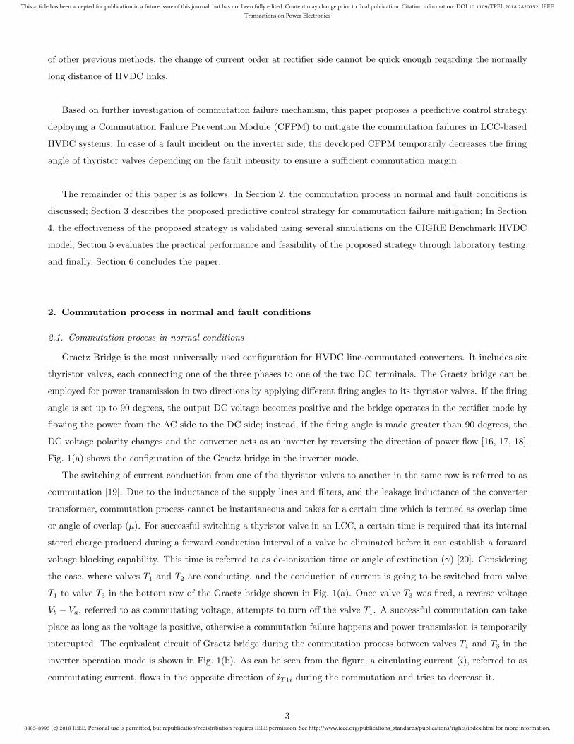
Fig. 1(a) shows the configuration of the Graetz bridge in the inverter mode.
The switching of current conduction from one of the thyristor valves to another in the same row is referred to as
commutation [19]. Due to the inductance of the supply lines and filters, and the leakage inductance of the converter
transformer, commutation process cannot be instantaneous and takes for a certain time which is termed as overlap time
or angle of overlap (µ). For successful switching a thyristor valve in an LCC, a certain time is required that its internal
stored charge produced during a forward conduction interval of a valve be eliminated before it can establish a forward
voltage blocking capability. This time is referred to as de-ionization time or angle of extinction (γ) [20]. Considering
the case, where valves T1 and T2 are conducting, and the conduction of current is going to be switched from valve
T1 to valve T3 in the bottom row of the Graetz bridge shown in Fig. 1(a). Once valve T3 was fired, a reverse voltage
Vb − Va, referred to as commutating voltage, attempts to turn off the valve T1. A successful commutation can take
place as long as the voltage is positive, otherwise a commutation failure happens and power transmission is temporarily
interrupted. The equivalent circuit of Graetz bridge during the commutation process between valves T1 and T3 in the
inverter operation mode is shown in Fig. 1(b). As can be seen from the figure, a circulating current (i), referred to as
commutating current, flows in the opposite direction of iT1i during the commutation and tries to decrease it.
3
0885-8993 (c) 2018 IEEE. Personal use is permitted, but republication/redistribution requires IEEE permission. See http://www.ieee.org/publications_standards/publications/rights/index.html for more information.
This article has been accepted for publication in a future issue of this journal, but has not been fully edited. Content may change prior to final publication. Citation information: DOI 10.1109/TPEL.2018.2820152, IEEE
Transactions on Power Electronics
T5
T2
T3
T6
T1
T4
T2
T3
T1
Idi
Lr Lc
Lc
Lc
n
Lr
Idi
iT1i
3-phase abc
a
b
c
Vdi
n
iT3i
iT2i
Vdi
i
Va
Vb
Vc
a)
b)
Figure 1: (a) Graetz bridge in the inverter mode. (b) The equivalent circuit of Graetz bridge during the commutation process betweenvalves T1 and T3 in the inverter mode.
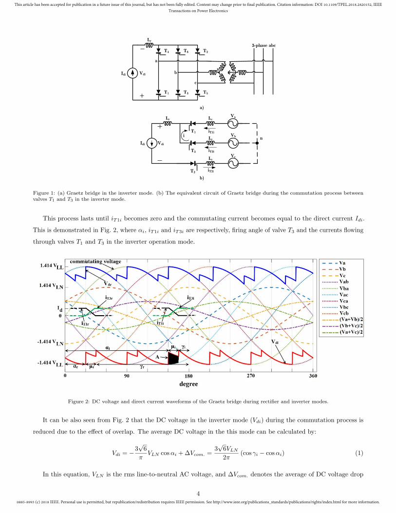
This process lasts until iT1i becomes zero and the commutating current becomes equal to the direct current Idi.
This is demonstrated in Fig. 2, where αi, iT1i and iT3i are respectively, firing angle of valve T3 and the currents flowing
through valves T1 and T3 in the inverter operation mode.
Figure 2: DC voltage and direct current waveforms of the Graetz bridge during rectifier and inverter modes.
It can be also seen from Fig. 2 that the DC voltage in the inverter mode (Vdi) during the commutation process is
reduced due to the effect of overlap. The average DC voltage in the this mode can be calculated by:
Vdi = −3√6
πVLN cosαi +∆Vcom. =
3√6VLN
2π(cos γi − cosαi) (1)
In this equation, VLN is the rms line-to-neutral AC voltage, and ∆Vcom. denotes the average of DC voltage drop
4
0885-8993 (c) 2018 IEEE. Personal use is permitted, but republication/redistribution requires IEEE permission. See http://www.ieee.org/publications_standards/publications/rights/index.html for more information.
This article has been accepted for publication in a future issue of this journal, but has not been fully edited. Content may change prior to final publication. Citation information: DOI 10.1109/TPEL.2018.2820152, IEEE
Transactions on Power Electronics
during comutation which can be expressed as:
∆Vcom. =3
πA = RcIdi (2)
Where, Rc =3
πωLc is the equivalent commutation resistance and A and is the area resulting from voltage drop
during the commutation which is shown in Fig.2. Also, Idi represents the direct current which can be calculated by:
Idi =
√6VLN
2ωLc
(cos γi + cosαi) (3)
The same analysis can also be performed for the rectifier operation mode except that valve T3 is fired at αr. It
can be seen from Fig. 2 that the remaining of commutating voltage in this mode (γr) is large enough for a successful
commutation, and hence commutation failures rarely happen in the rectifier mode.
2.2. Commutation process in fault conditions
As mentioned before, the risk of commutation failure in the inverter mode is much higher than that in the rectifier
mode. Because of this, commutation failures in LCC-based HVDC systems often take place in the inverter stations due
to the voltage disturbances resulting from the AC faults at their AC side [21]. AC faults can be of symmetrical three
phase or non-symmetrical type.
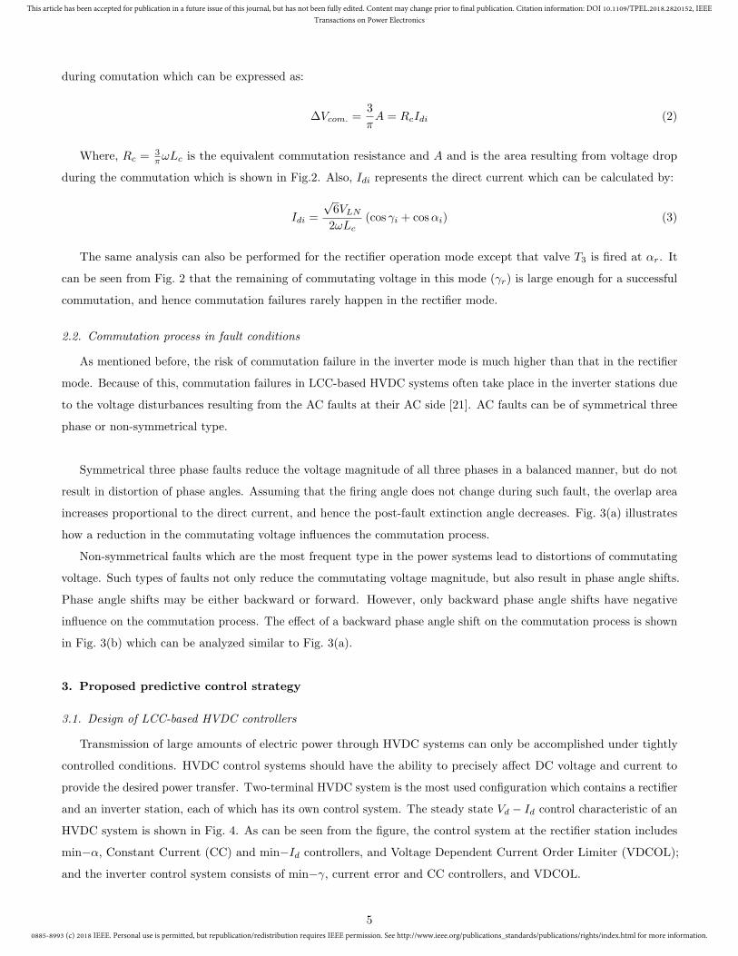
Symmetrical three phase faults reduce the voltage magnitude of all three phases in a balanced manner, but do not
result in distortion of phase angles. Assuming that the firing angle does not change during such fault, the overlap area
increases proportional to the direct current, and hence the post-fault extinction angle decreases. Fig. 3(a) illustrates
how a reduction in the commutating voltage influences the commutation process.
Non-symmetrical faults which are the most frequent type in the power systems lead to distortions of commutating
voltage. Such types of faults not only reduce the commutating voltage magnitude, but also result in phase angle shifts.
Phase angle shifts may be either backward or forward. However, only backward phase angle shifts have negative
influence on the commutation process. The effect of a backward phase angle shift on the commutation process is shown
in Fig. 3(b) which can be analyzed similar to Fig. 3(a).
3. Proposed predictive control strategy
3.1. Design of LCC-based HVDC controllers
Transmission of large amounts of electric power through HVDC systems can only be accomplished under tightly
controlled conditions. HVDC control systems should have the ability to precisely affect DC voltage and current to
provide the desired power transfer. Two-terminal HVDC system is the most used configuration which contains a rectifier
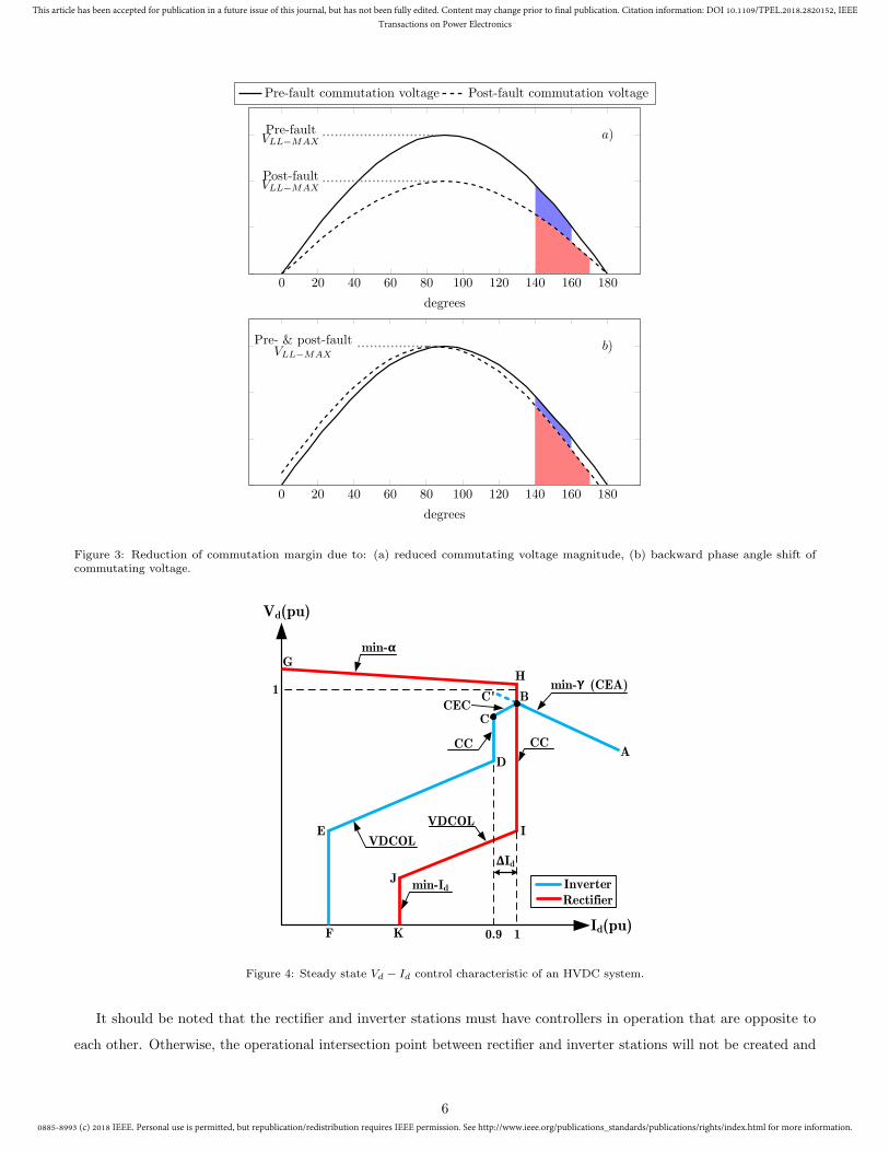
and an inverter station, each of which has its own control system. The steady state Vd − Id control characteristic of an
HVDC system is shown in Fig. 4. As can be seen from the figure, the control system at the rectifier station includes
min−α, Constant Current (CC) and min−Id controllers, and Voltage Dependent Current Order Limiter (VDCOL);
and the inverter control system consists of min−γ, current error and CC controllers, and VDCOL.
5
0885-8993 (c) 2018 IEEE. Personal use is permitted, but republication/redistribution requires IEEE permission. See http://www.ieee.org/publications_standards/publications/rights/index.html for more information.
This article has been accepted for publication in a future issue of this journal, but has not been fully edited. Content may change prior to final publication. Citation information: DOI 10.1109/TPEL.2018.2820152, IEEE
Transactions on Power Electronics
0 20 40 60 80 100 120 140 160 180
Post-faultVLL−MAX
Pre-faultVLL−MAX
a)
degrees
Pre-fault commutation voltage Post-fault commutation voltage
0 20 40 60 80 100 120 140 160 180
Pre- & post-faultVLL−MAX
b)
degrees
Figure 3: Reduction of commutation margin due to: (a) reduced commutating voltage magnitude, (b) backward phase angle shift ofcommutating voltage.
Vd(pu)
Id(pu)
min-Ƚ
min- (CEA)
CEC
VDCOL
VDCOL
0.9 1
1
CC CC
min-Id
A
B
C
C'
D
E
F
GH
I
J
K
ɀ
ȟId
RectifierInverter
Figure 4: Steady state Vd − Id control characteristic of an HVDC system.
It should be noted that the rectifier and inverter stations must have controllers in operation that are opposite to
each other. Otherwise, the operational intersection point between rectifier and inverter stations will not be created and
6
0885-8993 (c) 2018 IEEE. Personal use is permitted, but republication/redistribution requires IEEE permission. See http://www.ieee.org/publications_standards/publications/rights/index.html for more information.
This article has been accepted for publication in a future issue of this journal, but has not been fully edited. Content may change prior to final publication. Citation information: DOI 10.1109/TPEL.2018.2820152, IEEE
Transactions on Power Electronics
the control system will never become stable [22].
Measurement Unit
× 0
.01
Measurement Unit
Min
Id_order
PI Controller
PI ControllerMaxMin in 1 Cycle
Idi
Vdi
ɀiD ɀi
ɀmin -0.544 rad
Current Margin
= 0.1 pu
_+
++
+_
+_
Ⱦi_CC
Ⱦi_CEA
Idr to rectifier control system
+Min
ɀiY
ɀi _min_cycleCFPM output
Max
Ɏ
Ⱦi Ƚi to inverter valves
+
_ _
CEA Controller
CC Controller
CEC
VDCOL
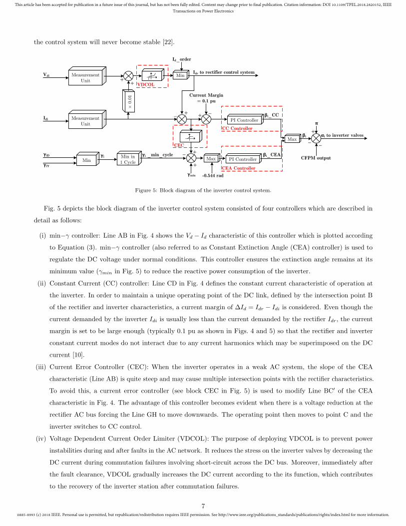
Figure 5: Block diagram of the inverter control system.
Fig. 5 depicts the block diagram of the inverter control system consisted of four controllers which are described in
detail as follows:
(i) min−γ controller: Line AB in Fig. 4 shows the Vd − Id characteristic of this controller which is plotted according
to Equation (3). min−γ controller (also referred to as Constant Extinction Angle (CEA) controller) is used to
regulate the DC voltage under normal conditions. This controller ensures the extinction angle remains at its
minimum value (γmin in Fig. 5) to reduce the reactive power consumption of the inverter.
(ii) Constant Current (CC) controller: Line CD in Fig. 4 defines the constant current characteristic of operation at
the inverter. In order to maintain a unique operating point of the DC link, defined by the intersection point B
of the rectifier and inverter characteristics, a current margin of ∆Id = Idr − Idi is considered. Even though the
current demanded by the inverter Idi is usually less than the current demanded by the rectifier Idr, the current
margin is set to be large enough (typically 0.1 pu as shown in Figs. 4 and 5) so that the rectifier and inverter
constant current modes do not interact due to any current harmonics which may be superimposed on the DC
current [10].
(iii) Current Error Controller (CEC): When the inverter operates in a weak AC system, the slope of the CEA
characteristic (Line AB) is quite steep and may cause multiple intersection points with the rectifier characteristics.
To avoid this, a current error controller (see block CEC in Fig. 5) is used to modify Line BC′ of the CEA
characteristic in Fig. 4. The advantage of this controller becomes evident when there is a voltage reduction at the
rectifier AC bus forcing the Line GH to move downwards. The operating point then moves to point C and the
inverter switches to CC control.
(iv) Voltage Dependent Current Order Limiter (VDCOL): The purpose of deploying VDCOL is to prevent power
instabilities during and after faults in the AC network. It reduces the stress on the inverter valves by decreasing the
DC current during commutation failures involving short-circuit across the DC bus. Moreover, immediately after
the fault clearance, VDCOL gradually increases the DC current according to the its function, which contributes
to the recovery of the inverter station after commutation failures.
7
0885-8993 (c) 2018 IEEE. Personal use is permitted, but republication/redistribution requires IEEE permission. See http://www.ieee.org/publications_standards/publications/rights/index.html for more information.
This article has been accepted for publication in a future issue of this journal, but has not been fully edited. Content may change prior to final publication. Citation information: DOI 10.1109/TPEL.2018.2820152, IEEE
Transactions on Power Electronics
Since the risk of commutation failure at the inverter station is higher than the rectifier one, the inverter control
system is also equipped with a Commutation Failure Prevention Module (CFPM). The function of CFPM is to predict
the commutation failures resulting from AC fault incidents as well as other system disturbances which may lead to
reduced commutation margins. More precisely, once a fault occurred, CFPM detects the possibility of commutation
failure by measuring the AC system instantaneous values, and then deducts an additional angle from the inverter firing
angle to enlarge the commutation margin, thereby reducing the probability of commutation failures.
3.2. Proposed Commutation Failure Prevention Module (CFPM)
As discussed in Section 1, one of the main drawbacks of the existing firing angle-based control strategies is that the
intensity of fault incident is neglected for determination of the reduced firing angle. In order to overcome this challenge,
this paper proposes a CFPM based on Thevenin’s impedance through Phasor Measurement Unit (PMU) measurements
at the inverter AC bus. Since the value of Thevenin’s impedance seen from the inverter AC bus decreases when the
fault severity increases, it can be a suitable parameter for determination of the fault severity and deduction of the
firing angle.
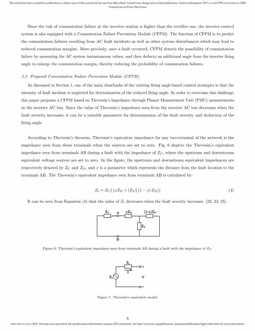
According to Thevenin’s theorem, Thevenin’s equivalent impedance for any two-terminal of the network is the
impedance seen from those terminals when the sources are set to zero. Fig. 6 depicts the Thevenin’s equivalent
impedance seen from terminals AB during a fault with the impedance of ZF , where the upstream and downstream
equivalent voltage sources are set to zero. In the figure, the upstream and downstream equivalent impedances are
respectively denoted by ZU and ZD, and x is a parameter which represents the distance from the fault location to the
terminals AB. The Thevenin’s equivalent impedance seen from terminals AB is calculated by:
Zt = ZU‖ (xZD + (ZF ‖ (1− x)ZD)) (4)
It can be seen from Equation (4) that the value of Zt decreases when the fault severity increases [23, 24, 25].
ZU A (1-x)ZDxZD
ZF
B
Figure 6: Thevenin’s equivalent impedance seen from terminals AB during a fault with the impedance of ZF .
Et
Zt
I
V
+
Figure 7: Thevenin’s equivalent model.
8
0885-8993 (c) 2018 IEEE. Personal use is permitted, but republication/redistribution requires IEEE permission. See http://www.ieee.org/publications_standards/publications/rights/index.html for more information.
This article has been accepted for publication in a future issue of this journal, but has not been fully edited. Content may change prior to final publication. Citation information: DOI 10.1109/TPEL.2018.2820152, IEEE
Transactions on Power Electronics
Based on Thevenin’s equivalent model shown in Fig. 7, the voltage equation at each node of power system can be
defined as:
V = Et − ZtI (5)
According to (5), the voltage equation at inverter AC bus becomes:
Vib = Etib − ZtibIib (6)
Where, Etib and Ztib represent Thevenin’s equivalent voltage source and Thevenin’s equivalent impedance seen from
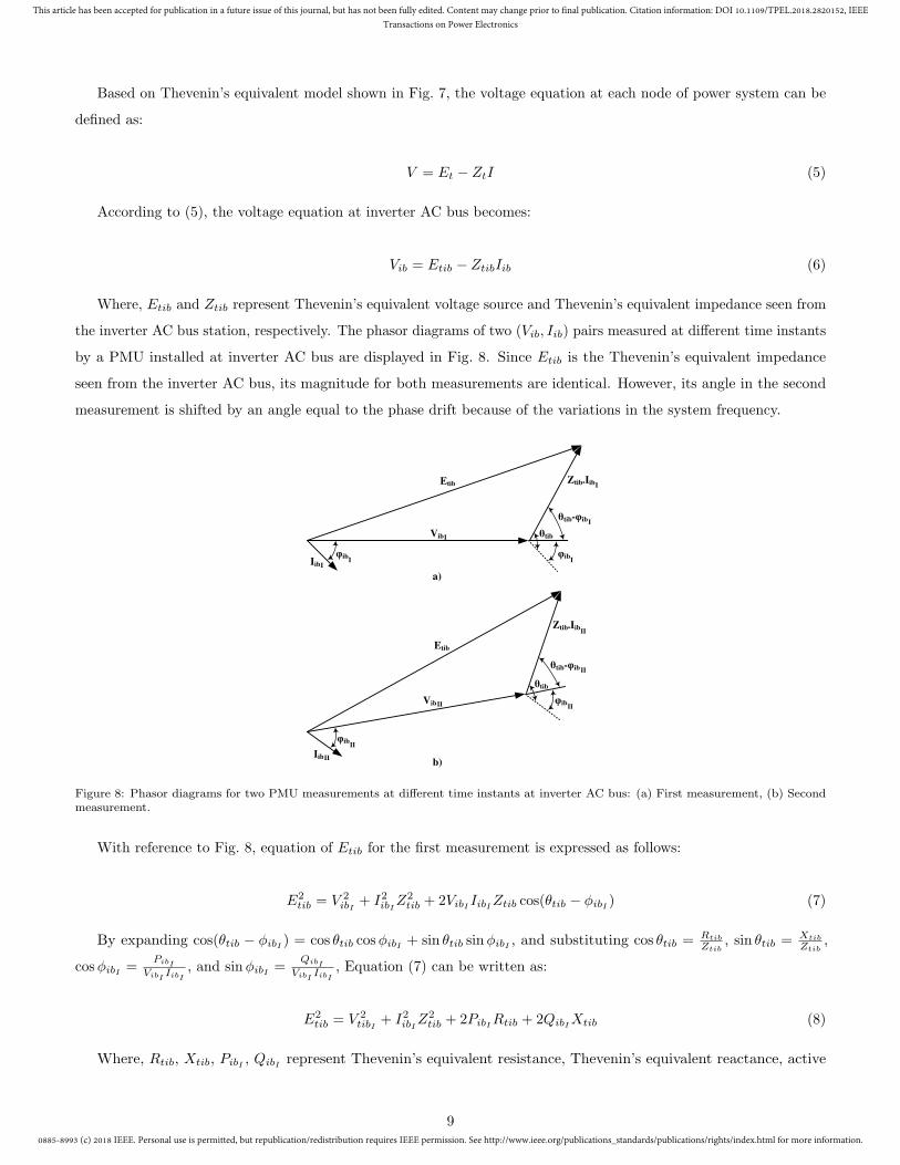
the inverter AC bus station, respectively. The phasor diagrams of two (Vib, Iib) pairs measured at different time instants
by a PMU installed at inverter AC bus are displayed in Fig. 8. Since Etib is the Thevenin’s equivalent impedance
seen from the inverter AC bus, its magnitude for both measurements are identical. However, its angle in the second
measurement is shifted by an angle equal to the phase drift because of the variations in the system frequency.
Etib Ztib.Iib
VibI
IibI
I
știb-ijib I
ijib I
știb
ijib I
Ztib.IibII
știb
știb-ijib II
Etib
VibII
ijib II
IibII
ijib II
a)
b)
Figure 8: Phasor diagrams for two PMU measurements at different time instants at inverter AC bus: (a) First measurement, (b) Secondmeasurement.
With reference to Fig. 8, equation of Etib for the first measurement is expressed as follows:
E2
tib = V 2
ibI+ I2ibIZ
2
tib + 2VibI IibIZtib cos(θtib − φibI ) (7)
By expanding cos(θtib − φibI ) = cos θtib cosφibI + sin θtib sinφibI , and substituting cos θtib = Rtib
Ztib
, sin θtib = Xtib
Ztib
,
cosφibI =PibI
VibIIibI
, and sinφibI =QibI
VibIIibI
, Equation (7) can be written as:
E2
tib = V 2
tibI+ I2ibIZ
2
tib + 2PibIRtib + 2QibIXtib (8)
Where, Rtib, Xtib, PibI , QibI represent Thevenin’s equivalent resistance, Thevenin’s equivalent reactance, active
9
0885-8993 (c) 2018 IEEE. Personal use is permitted, but republication/redistribution requires IEEE permission. See http://www.ieee.org/publications_standards/publications/rights/index.html for more information.
This article has been accepted for publication in a future issue of this journal, but has not been fully edited. Content may change prior to final publication. Citation information: DOI 10.1109/TPEL.2018.2820152, IEEE
Transactions on Power Electronics
power and reactive power at inverter AC bus, respectively.
By following the same procedure, equation of Etib for the second measurement can be expressed as:
E2
tib = V 2
tibII+ I2ibIIZ
2
tib + 2PibIIRtib + 2QibIIXtib (9)
By subtracting (9) from (8):
V 2
ibI− V 2
ibII+ (I2ibI − I2ibII )Z
2
tib + 2(PibI − PibII )Rtib + 2(QibI −QibII )Xtib (10)
By substituting Ztib =√
R2
tib +X2
tib and arranging (10):
(
Rtib +PibI − PibII
I2ibI − I2ibII
)2
+
(
Xtib +QibI −QibII
I2ibI − I2ibII
)2
=
V 2
ibII− V 2
ibI
I2ibI − I2ibII+
(
PibI − PibII
I2ibI − I2ibII
)2
+
(
QibI −QibII
I2ibI − I2ibII
)2
(11)
This is the equation of a circle with radius rI, II =
√
V 2
ibII−V 2
ibI
I2
ibI−I2
ibII
+
(PibI
−PibII
I2
ibI−I2
ibII
)2
+
(QibI
−QibII
I2
ibI−I2
ibII
)2
centered at
OI, II =
(PibII
−PibI
I2
ibI−I2
ibII
,QibII
−QibI
I2
ibI−I2
ibII
)
in the impedance plane which specifies a locus for Thevenin’s impedance seen from
the inverter AC bus. However, Equation (11) which is obtained by two (Vib, Iib) pairs measured at different time
instants cannot determine a certain value for Ztib. Hence, another measurement is required to be used with the first
and second measurements to create two other circles for Ztib. The intersection of these three circles specifies a certain
value for Ztib. It should be highlighted that since location, type and impedance of fault, and configuration of the
connected AC network have influence on the values of voltage and current measured at the inverter AC bus, the impact
of these factors are inherently taken into account in the obtained value of Ztib.
Assuming no losses in the inverter, the DC power fed into the inverter is equal to the AC power emanating from it:
VdiIdi = 3VibIib cosφib (12)
Substituting Vdi, Idi and Iib respectively from (1), (3) and (6) into (12), γi can be expressed by:
γi = arccos
√
2πωLc (Etib − Vib) cosφib
3VibZtib
+ cos2 αi
(13)
Assuming that the firing angle has not changed before CFPM activation, the required ∆α which should be deducted
10
0885-8993 (c) 2018 IEEE. Personal use is permitted, but republication/redistribution requires IEEE permission. See http://www.ieee.org/publications_standards/publications/rights/index.html for more information.
This article has been accepted for publication in a future issue of this journal, but has not been fully edited. Content may change prior to final publication. Citation information: DOI 10.1109/TPEL.2018.2820152, IEEE
Transactions on Power Electronics
from the valves’ firing angle order to prevent the commutation failure can be calculated by:
∆α = γmin − arccos
√
2πωLc (Etib − Vib) cosφib
3VibZtib
+ cos2 αi
︸ ︷︷ ︸
γi
(14)
where, γmin is the minimum extinction angle in which commutation failure does not occur, and γi is the reduced
extinction angle due to the AC fault. Equation (14) shows that decrease of Ztib increases ∆α. Moreover, it can be seen
from Equation (4) that increase of fault intensity leads to reduction of the Thevenin’s impedance. Therefore, more
severe faults require larger ∆α. However, it was observed in both simulation and experimental results that values
of ∆α larger than 0.476 rad contrarily cause more commutation failures. This can be also proved theoretically by
Equation (1), in which reducing the firing angle leads to more reduction in the DC voltage and increases the risk of
commutation failure. Therefore, Equation (14) was replaced by a look-up table, where the suitable ∆α (between 0 to
0.476 rad) is selected through comparing between pre- and post-fault values of Ztib. Moreover, deployment of look-up
table can significantly reduce the CFPM execution time, since retrieving a value from memory is much faster than
undergoing a complicated computation.
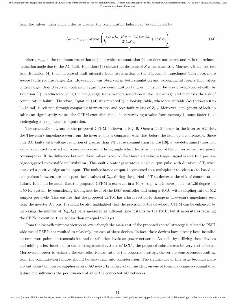
The schematic diagram of the proposed CFPM is shown in Fig. 9. Once a fault occurs in the inverter AC side,
the Thevenin’s impedance seen from the inverter bus is compared with that before the fault by a comparator. Since
only AC faults with voltage reduction of greater than 8% cause commutation failure [19], a pre-determined threshold
value is required to avoid unnecessary decrease of firing angle which leads to increase of the converter reactive power
consumption. If the difference between these values exceeded the threshold value, a trigger signal is sent to a positive
edge-triggered monostable multivibrator. This multivibrator generates a single output pulse with duration of T, when
it sensed a positive edge on its input. The multivibrator output is connected to a multiplexer to select a ∆α based on
comparison between pre- and post- fault values of Ztib during the period of T to decrease the risk of commutation
failure. It should be noted that the proposed CFPM is executed in a 70 µs step, which corresponds to 1.26 degrees in
a 50 Hz system, by considering the highest level of the DSP controller and using a PMU with sampling rate of 512
samples per cycle. This ensures that the proposed CFPM has a fast reaction to change in Thevenin’s impedance seen
from the inverter AC bus. It should be also highlighted that the precision of the developed CFPM can be enhanced by
increasing the number of (Vib, Iib) pairs measured at different time instants by the PMU, but it necessitates reducing
the CFPM execution time to less than or equal to 70 µs.
From the cost-effectiveness viewpoint, even though the main cost of the proposed control strategy is related to PMU,
wide use of PMUs has resulted to relatively low cost of these devices. In fact, these devices have already been installed
on numerous points on transmission and distribution levels on power networks. As such, by utilizing these devices
and adding a few functions to the existing control systems of LCCs, the proposed solution can be very cost-effective.
Moreover, in order to estimate the cost-effectiveness ratio of the proposed strategy, the serious consequences resulting
from the commutation failures should be also taken into consideration. The significance of this issue becomes more
evident when the inverter supplies several AC networks, where a fault incident on one of them may cause a commutation
failure and influences the performance of all of the connected AC networks.
11
0885-8993 (c) 2018 IEEE. Personal use is permitted, but republication/redistribution requires IEEE permission. See http://www.ieee.org/publications_standards/publications/rights/index.html for more information.
This article has been accepted for publication in a future issue of this journal, but has not been fully edited. Content may change prior to final publication. Citation information: DOI 10.1109/TPEL.2018.2820152, IEEE
Transactions on Power Electronics
PhasorMeasurement Unit (PMU)
Comparator
Ztib_threshold
+ _
Look-Up Table
Memory
Positive-EdgeMonostable
Multivibrator
Multiplexer0
Thevenin s Impedance Estimator
VibZtib(t) Ztib(t-1)
1
ȟȽselected 0
CFPM outputS
Iib
Figure 9: Schematic diagram of the proposed CFPM.
4. Test network and case studies
4.1. Test network
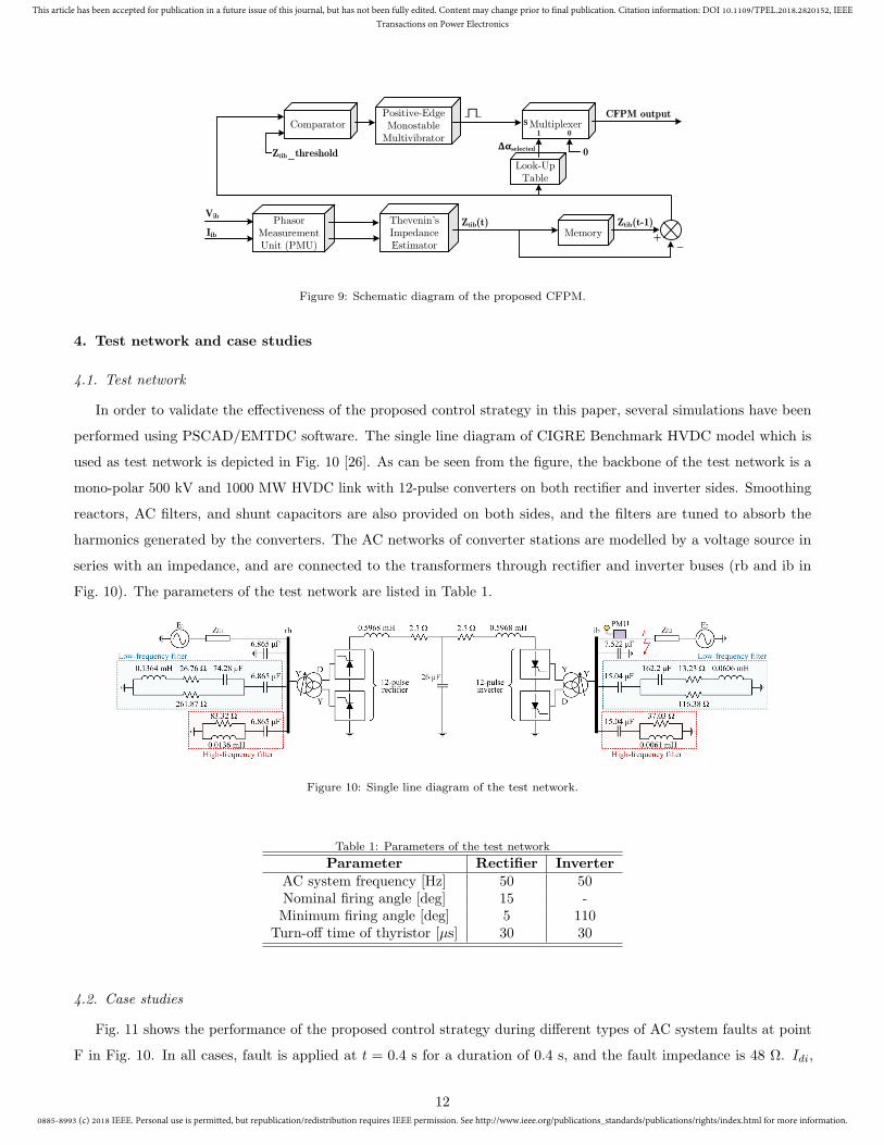
In order to validate the effectiveness of the proposed control strategy in this paper, several simulations have been
performed using PSCAD/EMTDC software. The single line diagram of CIGRE Benchmark HVDC model which is
used as test network is depicted in Fig. 10 [26]. As can be seen from the figure, the backbone of the test network is a
mono-polar 500 kV and 1000 MW HVDC link with 12-pulse converters on both rectifier and inverter sides. Smoothing
reactors, AC filters, and shunt capacitors are also provided on both sides, and the filters are tuned to absorb the
harmonics generated by the converters. The AC networks of converter stations are modelled by a voltage source in
series with an impedance, and are connected to the transformers through rectifier and inverter buses (rb and ib in
Fig. 10). The parameters of the test network are listed in Table 1.
Figure 10: Single line diagram of the test network.
Table 1: Parameters of the test network
Parameter Rectifier Inverter
AC system frequency [Hz] 50 50Nominal firing angle [deg] 15 -Minimum firing angle [deg] 5 110
Turn-off time of thyristor [µs] 30 30
4.2. Case studies
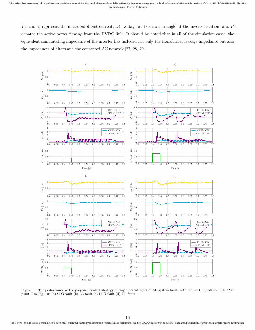
Fig. 11 shows the performance of the proposed control strategy during different types of AC system faults at point
F in Fig. 10. In all cases, fault is applied at t = 0.4 s for a duration of 0.4 s, and the fault impedance is 48 Ω. Idi,
12
0885-8993 (c) 2018 IEEE. Personal use is permitted, but republication/redistribution requires IEEE permission. See http://www.ieee.org/publications_standards/publications/rights/index.html for more information.
This article has been accepted for publication in a future issue of this journal, but has not been fully edited. Content may change prior to final publication. Citation information: DOI 10.1109/TPEL.2018.2820152, IEEE
Transactions on Power Electronics
Vdi and γi represent the measured direct current, DC voltage and extinction angle at the inverter station; also P
denotes the active power flowing from the HVDC link. It should be noted that in all of the simulation cases, the
equivalent commutating impedance of the inverter has included not only the transformer leakage impedance but also
the impedances of filters and the connected AC network [27, 28, 29].
0.3 0.35 0.4 0.45 0.5 0.55 0.6 0.65 0.7 0.75 0.80
0.5
1
I di[p.u.]
a)
0.3 0.35 0.4 0.45 0.5 0.55 0.6 0.65 0.7 0.75 0.80
0.5
1
I di[p.u.]
c)
0.3 0.35 0.4 0.45 0.5 0.55 0.6 0.65 0.7 0.75 0.80
0.5
1
Vdi[p.u.]
0.3 0.35 0.4 0.45 0.5 0.55 0.6 0.65 0.7 0.75 0.80
0.5
1
Vdi[p.u.]
0.3 0.35 0.4 0.45 0.5 0.55 0.6 0.65 0.7 0.75 0.80
0.5
1
1.5
P[p.u.] CFPM ON
CFPM OFF
0.3 0.35 0.4 0.45 0.5 0.55 0.6 0.65 0.7 0.75 0.80
0.5
1
1.5
P[p.u.] CFPM ON
CFPM OFF
0.3 0.35 0.4 0.45 0.5 0.55 0.6 0.65 0.7 0.75 0.80
1
2
3
4
γi[rad
] CFPM ONCFPM OFF
0.3 0.35 0.4 0.45 0.5 0.55 0.6 0.65 0.7 0.75 0.80
1
2
3
4γi[rad
] CFPM ONCFPM OFF
0.3 0.35 0.4 0.45 0.5 0.55 0.6 0.65 0.7 0.75 0.80
0.2
0.4
Time [s]
CFPM
][rad
]
0.3 0.35 0.4 0.45 0.5 0.55 0.6 0.65 0.7 0.75 0.80
0.2
0.4
Time [s]
CFPM
][rad
]
0.3 0.35 0.4 0.45 0.5 0.55 0.6 0.65 0.7 0.75 0.80
0.5
1
I di[p.u.]
b)
0.3 0.35 0.4 0.45 0.5 0.55 0.6 0.65 0.7 0.75 0.80
0.5
1
I di[p.u.]
d)
0.3 0.35 0.4 0.45 0.5 0.55 0.6 0.65 0.7 0.75 0.80
0.5
1
Vdi[p.u.]
0.3 0.35 0.4 0.45 0.5 0.55 0.6 0.65 0.7 0.75 0.80
0.5
1
Vdi[p.u.]
0.3 0.35 0.4 0.45 0.5 0.55 0.6 0.65 0.7 0.75 0.80
0.5
1
1.5
P[p.u.] CFPM ONCFPM OFF
0.3 0.35 0.4 0.45 0.5 0.55 0.6 0.65 0.7 0.75 0.80
0.5
1
1.5
P[p.u.] CFPM ON
CFPM OFF
0.3 0.35 0.4 0.45 0.5 0.55 0.6 0.65 0.7 0.75 0.80
1
2
3
4
γi[rad] CFPM ON
CFPM OFF
0.3 0.35 0.4 0.45 0.5 0.55 0.6 0.65 0.7 0.75 0.80
1
2
3
4
γi[rad
] CFPM ONCFPM OFF
0.3 0.35 0.4 0.45 0.5 0.55 0.6 0.65 0.7 0.75 0.80
0.2
0.4
Time [s]
CFPM
][rad]
0.3 0.35 0.4 0.45 0.5 0.55 0.6 0.65 0.7 0.75 0.80
0.2
0.4
Time [s]
CFPM
][rad]
Figure 11: The performance of the proposed control strategy during different types of AC system faults with the fault impedance of 48 Ω atpoint F in Fig. 10: (a) SLG fault (b) LL fault (c) LLG fault (d) TP fault.
13
0885-8993 (c) 2018 IEEE. Personal use is permitted, but republication/redistribution requires IEEE permission. See http://www.ieee.org/publications_standards/publications/rights/index.html for more information.
This article has been accepted for publication in a future issue of this journal, but has not been fully edited. Content may change prior to final publication. Citation information: DOI 10.1109/TPEL.2018.2820152, IEEE
Transactions on Power Electronics
Referring to Fig. 11(a), when a Single-Line-to-Ground (SLG) fault occurs on phase A at t = 0.4 s, AC voltage
decreases and the involved commutating voltages are distorted in phase and reduced in magnitude, which results in
reduction of DC voltage Vdi magnitude due to principles of AC/DC conversion. This sudden drop in Vdi, causes Idi to
increase to remain the active power P at the rated power of inverter station according to P = VdiIdi. Since the overlap
angle (µ) is directly proportional to the direct current, it also increases and reduces the extinction angle (γi), leading to
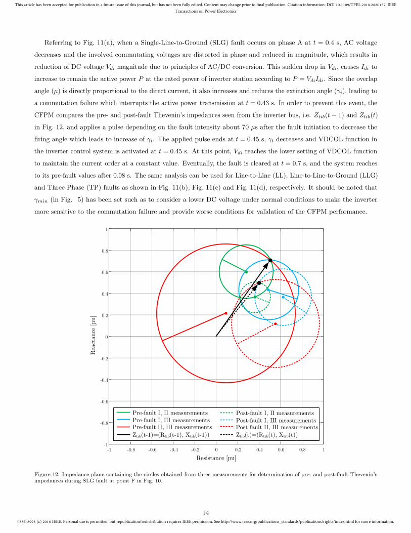
a commutation failure which interrupts the active power transmission at t = 0.43 s. In order to prevent this event, the
CFPM compares the pre- and post-fault Thevenin’s impedances seen from the inverter bus, i.e. Ztib(t− 1) and Ztib(t)
in Fig. 12, and applies a pulse depending on the fault intensity about 70 µs after the fault initiation to decrease the
firing angle which leads to increase of γi. The applied pulse ends at t = 0.45 s, γi decreases and VDCOL function in
the inverter control system is activated at t = 0.45 s. At this point, Vdi reaches the lower setting of VDCOL function
to maintain the current order at a constant value. Eventually, the fault is cleared at t = 0.7 s, and the system reaches
to its pre-fault values after 0.08 s. The same analysis can be used for Line-to-Line (LL), Line-to-Line-to-Ground (LLG)
and Three-Phase (TP) faults as shown in Fig. 11(b), Fig. 11(c) and Fig. 11(d), respectively. It should be noted that
γmin (in Fig. 5) has been set such as to consider a lower DC voltage under normal conditions to make the inverter
more sensitive to the commutation failure and provide worse conditions for validation of the CFPM performance.
-1 -0.8 -0.6 -0.4 -0.2 0 0.2 0.4 0.6 0.8 1-1
-0.8
-0.6
-0.4
-0.2
0
0.2
0.4
0.6
0.8
1
Rea
ctan
ce [pu]
Resistance [pu]
Pre-fault I, III measurements Pre-fault II, III measurements
Post-fault I, II measurements Post-fault I, III measurements Post-fault II, III measurements
Ztib(t-1)=(Rtib(t-1), Xtib(t-1)) Ztib(t)=(Rtib(t), Xtib(t))
Pre-fault I, II measurements
Figure 12: Impedance plane containing the circles obtained from three measurements for determination of pre- and post-fault Thevenin’simpedances during SLG fault at point F in Fig. 10.
14
0885-8993 (c) 2018 IEEE. Personal use is permitted, but republication/redistribution requires IEEE permission. See http://www.ieee.org/publications_standards/publications/rights/index.html for more information.
This article has been accepted for publication in a future issue of this journal, but has not been fully edited. Content may change prior to final publication. Citation information: DOI 10.1109/TPEL.2018.2820152, IEEE
Transactions on Power Electronics
0.400
0.402
0.404
0.406
0.408
0.410
0.412
0.414
0.416
0.418
0
20
40
60
80
100
120
Fault Initiation Time [s]
Fau
ltIm
pedan
ce[Ω]
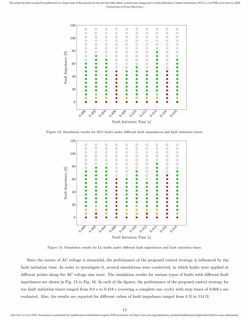
Figure 13: Simulation results for SLG faults under different fault impedances and fault initiation times.
0.400
0.402
0.404
0.406
0.408
0.410
0.412
0.414
0.416
0.418
0
20
40
60
80
100
120
Fault Initiation Time [s]
Fau
ltIm
pedan
ce[Ω]
Figure 14: Simulation results for LL faults under different fault impedances and fault initiation times.
Since the nature of AC voltage is sinusoidal, the performance of the proposed control strategy is influenced by the
fault initiation time. In order to investigate it, several simulations were conducted, in which faults were applied at
different points along the AC voltage sine wave. The simulation results for various types of faults with different fault
impedances are shown in Fig. 13 to Fig. 16. In each of the figures, the performance of the proposed control strategy for
ten fault initiation times ranged from 0.4 s to 0.418 s (covering a complete one cycle) with step times of 0.002 s are
evaluated. Also, the results are reported for different values of fault impedance ranged from 0 Ω to 114 Ω.
15
0885-8993 (c) 2018 IEEE. Personal use is permitted, but republication/redistribution requires IEEE permission. See http://www.ieee.org/publications_standards/publications/rights/index.html for more information.
This article has been accepted for publication in a future issue of this journal, but has not been fully edited. Content may change prior to final publication. Citation information: DOI 10.1109/TPEL.2018.2820152, IEEE
Transactions on Power Electronics
0.400
0.402
0.404
0.406
0.408
0.410
0.412
0.414
0.416
0.418
0
20
40
60
80
100
120
Fault Initiation Time [s]
Fau
ltIm
pedan
ce[Ω]
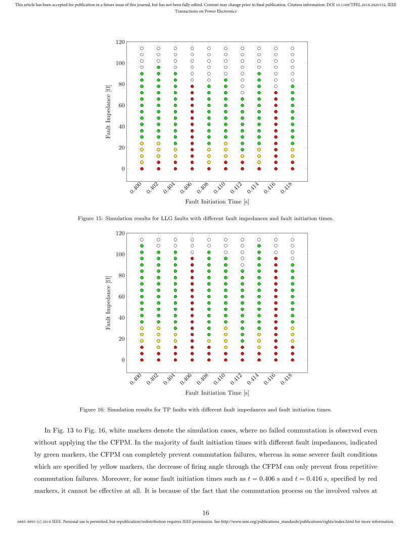
Figure 15: Simulation results for LLG faults with different fault impedances and fault initiation times.
0.400
0.402
0.404
0.406
0.408
0.410
0.412
0.414
0.416
0.418
0
20
40
60
80
100
120
Fault Initiation Time [s]
Fau
ltIm
pedan
ce[Ω]
Figure 16: Simulation results for TP faults with different fault impedances and fault initiation times.
In Fig. 13 to Fig. 16, white markers denote the simulation cases, where no failed commutation is observed even
without applying the the CFPM. In the majority of fault initiation times with different fault impedances, indicated
by green markers, the CFPM can completely prevent commutation failures, whereas in some severer fault conditions
which are specified by yellow markers, the decrease of firing angle through the CFPM can only prevent from repetitive
commutation failures. Moreover, for some fault initiation times such as t = 0.406 s and t = 0.416 s, specified by red
markers, it cannot be effective at all. It is because of the fact that the commutation process on the involved valves at
16
0885-8993 (c) 2018 IEEE. Personal use is permitted, but republication/redistribution requires IEEE permission. See http://www.ieee.org/publications_standards/publications/rights/index.html for more information.
This article has been accepted for publication in a future issue of this journal, but has not been fully edited. Content may change prior to final publication. Citation information: DOI 10.1109/TPEL.2018.2820152, IEEE
Transactions on Power Electronics
such time instants is going to start immediately, or is ongoing; also, the red cells in other time instants represent the
simulation cases, where the fault impedances are too low and the CFPM cannot inhibit the commutation failure. Such
a behavior was explained in Subsection 3.2 that values of ∆α larger than 0.476 rad contrarily cause more commutation
failures. Therefore, the proposed CFPM has been designed to prevent commutation failure or repetitive commutation
failures with a maximum ∆α of 0.476 rad.
5. Hardware in the loop testing
5.1. Experimental setup
In order to further validate the performance of the proposed control strategy under real-time conditions, a hardware
prototype has been developed. For such a development, the Opal-RT OP5600 HILBOX has been used, integrating
digital-analog I/O and GPS cards. More precisely, the system is equipped with an OP5330 analog-out card (16
single-ended digital output channels with a 16-bit resolution D/A converter), an OP5340 analog-in card and a GPS
TSync-PCIe card.
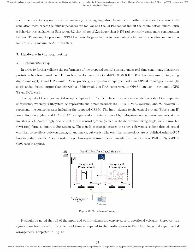
The layout of the experimental setup is depicted in Fig. 17. The entire real-time model consists of two separate
subsystems, whereby ‘Subsystem A’ represents the power network (i.e. LCC-HVDC system), and ‘Subsystem B’
represents the control system including the proposed CFPM. The input signals to the control system (Subsystem B)
are extinction angles, and DC and AC voltages and currents produced by Subsystem A (i.e. measurements at the
inverter side). Accordingly, the output of the control system (which is the determined firing angle for the inverter
thyristors) forms an input to Subsystem A. The signals’ exchange between these two subsystems is done through actual
electrical connections between analog-in and analog-out cards. The electrical connections are established using DB-37
breakout slim boards. Also, in order to get time-synchronized measurements (i.e. realization of PMU) TSync-PCIe
GPS card is applied.
Figure 17: Experimental setup.
It should be noted that all of the input and output signals are converted to proportional voltages. Moreover, the
signals have been scaled up by a factor of three (compared to the results shown in Fig. 11). The actual experimental
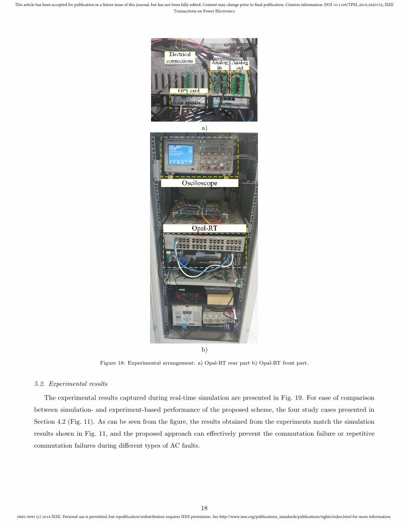
arrangement is depicted in Fig. 18.
17
0885-8993 (c) 2018 IEEE. Personal use is permitted, but republication/redistribution requires IEEE permission. See http://www.ieee.org/publications_standards/publications/rights/index.html for more information.
This article has been accepted for publication in a future issue of this journal, but has not been fully edited. Content may change prior to final publication. Citation information: DOI 10.1109/TPEL.2018.2820152, IEEE
Transactions on Power Electronics
a)
b)
Figure 18: Experimental arrangement: a) Opal-RT rear part b) Opal-RT front part.
5.2. Experimental results
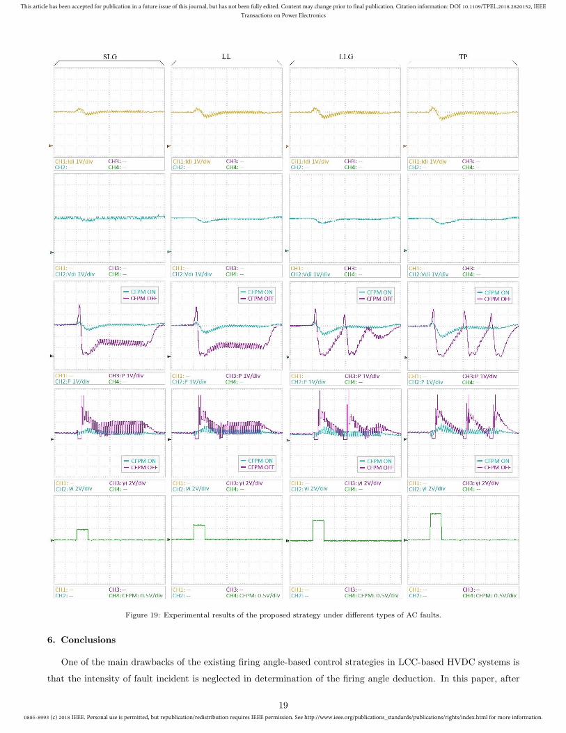
The experimental results captured during real-time simulation are presented in Fig. 19. For ease of comparison
between simulation- and experiment-based performance of the proposed scheme, the four study cases presented in
Section 4.2 (Fig. 11). As can be seen from the figure, the results obtained from the experiments match the simulation
results shown in Fig. 11, and the proposed approach can effectively prevent the commutation failure or repetitive
commutation failures during different types of AC faults.
18
0885-8993 (c) 2018 IEEE. Personal use is permitted, but republication/redistribution requires IEEE permission. See http://www.ieee.org/publications_standards/publications/rights/index.html for more information.
This article has been accepted for publication in a future issue of this journal, but has not been fully edited. Content may change prior to final publication. Citation information: DOI 10.1109/TPEL.2018.2820152, IEEE
Transactions on Power Electronics
Figure 19: Experimental results of the proposed strategy under different types of AC faults.
6. Conclusions
One of the main drawbacks of the existing firing angle-based control strategies in LCC-based HVDC systems is
that the intensity of fault incident is neglected in determination of the firing angle deduction. In this paper, after
19
0885-8993 (c) 2018 IEEE. Personal use is permitted, but republication/redistribution requires IEEE permission. See http://www.ieee.org/publications_standards/publications/rights/index.html for more information.
This article has been accepted for publication in a future issue of this journal, but has not been fully edited. Content may change prior to final publication. Citation information: DOI 10.1109/TPEL.2018.2820152, IEEE
Transactions on Power Electronics
further investigation of communication failure mechanism, a predictive control strategy was proposed, in which the
difference between pre- and post- fault values of Thevenin’s impedance seen from the inverter AC bus was utilized for
determination of fault severity and deduction of the firing angle. To verify the feasibility of the proposed approach,
SLG, LL, LLG, and TP faults with diverse fault impedances and fault initiation times were applied to an LCC-HVDC
test network. The simulation and experimental results indicated that the proposed approach is able to considerably
prevent the commutation failure or repetitive commutation failures during different types of AC faults.
Acknowledgement
The present article outlines the result of a collaborative work conducted between Tsinghua University, Beijing,
People’s Republic of China, Strathclyde University, Glasgow, United Kingdom, and Universiti Teknologi Malaysia,
Johor, Malaysia. This work is supported in part by the National Natural Science Foundation of China (Grant No.
51120175001), in part by the National Key Research and Development Plan of China (Grant No. 2016YFB0900600),
and in part by Royal Society of Edinburgh (J. M. Lessells Scholarship).
References
[1] J. Wu, H. Li, G. Wang, Y. Liang, An improved traveling-wave protection scheme for LCC-HVDC transmission
lines, IEEE Transactions on Power Delivery 32 (1) (2017) 106–116.
[2] H. Xiao, Y. Li, R. Liu, X. Duan, Single-end time-domain transient electrical signals based protection principle and
its efficient setting calculation method for LCC-HVDC lines, IET Generation, Transmission Distribution 11 (5)
(2017) 1233–1242.
[3] Y. Xue, X. P. Zhang, Reactive power and ac voltage control of LCC HVDC system with controllable capacitors,
IEEE Transactions on Power Systems 32 (1) (2017) 753–764.
[4] C. Guo, Y. Zhang, A. M. Gole, C. Zhao, Analysis of dual-infeed HVDC with LCC HVDC and VSC HVDC, IEEE
Transactions on Power Delivery 27 (3) (2012) 1529–1537.
[5] C. V. Thio, J. B. Davies, K. L. Kent, Commutation failures in HVDC transmission systems, IEEE Transactions
on Power Delivery 11 (2) (1996) 946–957.
[6] J. Zhu, Y. Li, X. Duan, Application of SFCLs to inhibit commutation failure in HVDC systems: Position
comparison and resistance recommendation, Canadian Journal of Electrical and Computer Engineering 40 (1)
(2017) 31–40.
[7] X. Zhou, Simultaneous commutation failures and forced blocking of multi-in-feed HVDC in east china power grid,
in: CIGRE Large Disturbances Workshop, 2014, pp. 21–32.
[8] L. Liu, The study of fuzzy controller in MTDC system, Power System Technology (Chinese) 22 (9) (1998) 22–26.
20
0885-8993 (c) 2018 IEEE. Personal use is permitted, but republication/redistribution requires IEEE permission. See http://www.ieee.org/publications_standards/publications/rights/index.html for more information.
This article has been accepted for publication in a future issue of this journal, but has not been fully edited. Content may change prior to final publication. Citation information: DOI 10.1109/TPEL.2018.2820152, IEEE
Transactions on Power Electronics
[9] T. Machida, Y. Yoshida, A method to detect the deionization margin angle and to prevent the commutation
failure of an inverter for DC transmission, IEEE Transactions on Power Apparatus and Systems PAS-86 (3) (1967)
259–262.
[10] K. Vijay, HVDC and FACTs controllers: Applications of static converters in power systems, Kluwer Academic
Publishers - Boston, 2004.
[11] S. Tamai, H. Naitoh, F. Ishiguro, M. Sato, K. Yamaji, N. Honjo, Fast and predictive HVDC extinction angle
control, IEEE Transactions on Power Systems 12 (3) (1997) 1268–1275.
[12] J. V. Wijayakulasooriya, G. A. Putrus, C. H. Ng, Fast non-recursive extraction of individual harmonics using
artificial neural networks, IEE Proceedings - Generation, Transmission and Distribution 152 (4) (2005) 539–543.
doi:10.1049/ip-gtd:20045089.
[13] A. Hansen, H. Havemann, Decreasing the commutation failure frequency in HVDC transmission systems, IEEE
Transactions on Power Delivery 15 (3) (2000) 1022–1026.
[14] L. Zhang, L. Dofnas, A novel method to mitigate commutation failures in HVDC systems, in: International
Conference on Power System Technology, Vol. 1, 2002, pp. 51–56 vol.1.
[15] Z. Wei, Y. Yuan, X. Lei, H. Wang, G. Sun, Y. Sun, Direct-current predictive control strategy for inhibiting
commutation failure in HVDC converter, IEEE Transactions on Power Systems 29 (5) (2014) 2409–2417.
[16] C. Guo, C. Li, C. Zhao, X. Ni, K. Zha, W. Xu, An evolutional line-commutated converter integrated with
thyristor-based full-bridge module to mitigate the commutation failure, IEEE Transactions on Power Electronics
32 (2) (2017) 967–976.
[17] Z. Liu, J. Yu, X. Guo, T. Sun, J. Zhang, Survey of technologies of line commutated converter based high voltage
direct current transmission in china, CSEE Journal of Power and Energy Systems 1 (2) (2015) 1–8.
[18] J. G. Mayordomo, . Carbonero, L. F. Beites, R. Asensi, W. Xu, A contribution towards a general and systematic
procedure for modeling line commutated AC/DC converters in the harmonic domain, IEEE Transactions on Power
Delivery 24 (4) (2009) 2415–2427.
[19] I. Oketch, Improvement in algorithm for commutation failure prevention in LCC HVDC, Master’s thesis, University
of Technology, Gothenburg, Sweden (2016).
[20] O. E. Oni, I. E. Davidson, K. N. I. Mbangula, A review of LCC-HVDC and VSC-HVDC technologies and
applications, in: IEEE 16th International Conference on Environment and Electrical Engineering (EEEIC), 2016,
pp. 1–7.
[21] Z. Wei, J. Liu, W. Fang, J. Hou, Z. Xiang, Commutation failure analysis in single- and multi-infeed HVDC systems,
in: IEEE PES Asia-Pacific Power and Energy Engineering Conference(APPEEC), 2016, pp. 2244–2249.
[22] C. D. Barker, R. S. Whitehouse, R. Gupta, M. Li, Static characteristics of LCC converters in a multi-terminal
configuration, in: 13th IET International Conference on AC and DC Power Transmission, 2017, pp. 1–5.
21
0885-8993 (c) 2018 IEEE. Personal use is permitted, but republication/redistribution requires IEEE permission. See http://www.ieee.org/publications_standards/publications/rights/index.html for more information.
This article has been accepted for publication in a future issue of this journal, but has not been fully edited. Content may change prior to final publication. Citation information: DOI 10.1109/TPEL.2018.2820152, IEEE
Transactions on Power Electronics
[23] M. Khajeh, Protection of hybrid AC/DC grids based on thevenins theorem, Phd thesis, Faculty of Electrical
Engineering, University Teknologi Malaysia (UTM) (2016).
[24] M. R. Miveh, M. Gandomkar, S. Mirsaeidi, M. R. Gharibdoost, A review on protection challenges in microgrids,
in: 2012 Proceedings of 17th Conference on Electrical Power Distribution, 2012, pp. 1–5.
[25] B. Alinejad, H. K. Karegar, On-line thevenin impedance estimation based on PMU data and phase drift correction,
IEEE Transactions on Smart Grid PP (99) (2016) 1–1. doi:10.1109/TSG.2016.2574765.
[26] M. O. Faruque, Y. Zhang, V. Dinavahi, Detailed modeling of CIGRE HVDC benchmark system using
PSCAD/EMTDC and PSB/SIMULINK, IEEE Transactions on Power Delivery 21 (1) (2006) 378–387.
[27] Y. Li, F. Liu, L. Luo, C. Rehtanz, Y. Cao, Enhancement of commutation reliability of an HVDC inverter by
means of an inductive filtering method, IEEE Transactions on Power Electronics 28 (11) (2013) 4917–4929.
[28] Y. Li, L. Luo, C. Rehtanz, S. Rberg, F. Liu, Realization of reactive power compensation near the LCC-HVDC
converter bridges by means of an inductive filtering method, IEEE Transactions on Power Electronics 27 (9) (2012)
3908–3923.
[29] Y. Li, L. Luo, C. Rehtanz, D. Yang, S. Rberg, F. Liu, Harmonic transfer characteristics of a new HVDC system
based on an inductive filtering method, IEEE Transactions on Power Electronics 27 (5) (2012) 2273–2283.
Biographies
Sohrab Mirsaeidi (M’17) received his Ph.D. degree in Electrical Engineering from Universiti
Teknologi Malaysia (UTM), Johor, Malaysia in 2016. Currently, he is a Postdoctoral Fellow with
the Department of Electrical Engineering, Tsinghua University, Beijing, China. Dr. Mirsaeidi
has published more than 40 scientific papers and books in the field of control and protection of
power systems. He has also been involved in several key research projects funded by the Chinese
government. His main research interests include control and protection of large hybrid AC/DC grids,
distributed generation, and microgrids.
Xinzhou Dong (M’99 - SM’01 - F’16) was born in Shaanxi, China, in 1963. He received the
B.Sc., M.Sc., and Ph.D. degrees in Electrical Engineering from Xi’an Jiaotong University, China,
in 1983, 1991, and 1996, respectively. He furthered his postdoctoral research at the Electrical
Engineering Station of Tianjin University, Tianjin, China, from 1997 to 1998. Since 1999, he has
been employed by Tsinghua University, Beijing, China. Currently, he is a Professor with Dept. of
Electrical Engineering, Tsinghua University and Director of the International Union Research Center
of Beijing on Green Energy and Power Safety. His research interests include protective relaying,
fault location, and the application of wavelet transforms in power systems. Prof. Dong is a Fellow of IEEE and IET.
He is an author or co-author of more than 200 journal papers.
22

0885-8993 (c) 2018 IEEE. Personal use is permitted, but republication/redistribution requires IEEE permission. See http://www.ieee.org/publications_standards/publications/rights/index.html for more information.
This article has been accepted for publication in a future issue of this journal, but has not been fully edited. Content may change prior to final publication. Citation information: DOI 10.1109/TPEL.2018.2820152, IEEE
Transactions on Power Electronics
Dimitrios Tzelepis (S’13 - M’17) received the B.Eng in Electrical Engineering, the M.Sc in
Wind Energy Systems, and Ph.D in Protection, Fault Location and Control in MTDC grids from
Technological Education Institution of Athens (2013) and University of Strathclyde (2014) and
(2017) respectively. He is currently a Post-Doctoral Researcher with Department of Electronic and
Electrical Engineering, University of Strathclyde, Glasgow, U.K. His main research interests include
power systems protection, relay algorithms, application of advanced signal analysis in protection
and fault location applications and HVDC protection, fault location and control.
Dalila Mat Said (M’13) is a Senior Lecturer at Centre of Electrical Energy Systems, Fac-
ulty of Electrical Engineering, Universiti Teknologi Malaysia (UTM). She has 12 years of ex-
perience in teaching electrical engineering courses and supervision of more than 30 undergradu-
ates, and 20 post graduates students. She has an experience within the area of power quality
consultancy. She was involved in the Power Quality Baseline Study in a Peninsular Malaysia
(2010-2013) under the Energy Commission of Malaysia. She is a member of IEM, IET and
IEEE.
Adam Dysko (M’06) received the Ph.D. degree in Electrical and Electronic engineer-
ing from the University of Strathclyde, Glasgow, U.K., in 1998. He is currently
a Senior Lecturer with the Department of Electronic and Electrical Engineering. He
teaches a variety of Electrical Engineering subjects and has been leading a number
of research projects with both academic and industrial partners. His research inter-
ests include power system protection, system control and stability, and power qual-
ity.
Campbell Booth received the B.Eng. and Ph.D. degrees in electrical and electronic engineering
from the University of Strathclyde, Glasgow, UK in 1991 and 1996, respectively. He is currently
a Professor and Head of Department for Electronic and Electrical Engineering, University of
Strathclyde. His research interests include power system protection; plant condition monitoring
and intelligent asset management; applications of intelligent system techniques to power system
monitoring, protection, and control; knowledge management; and decision support systems.
23