Embed Size (px)
Citation preview
Think future. Switch to green.
www.moeller.net
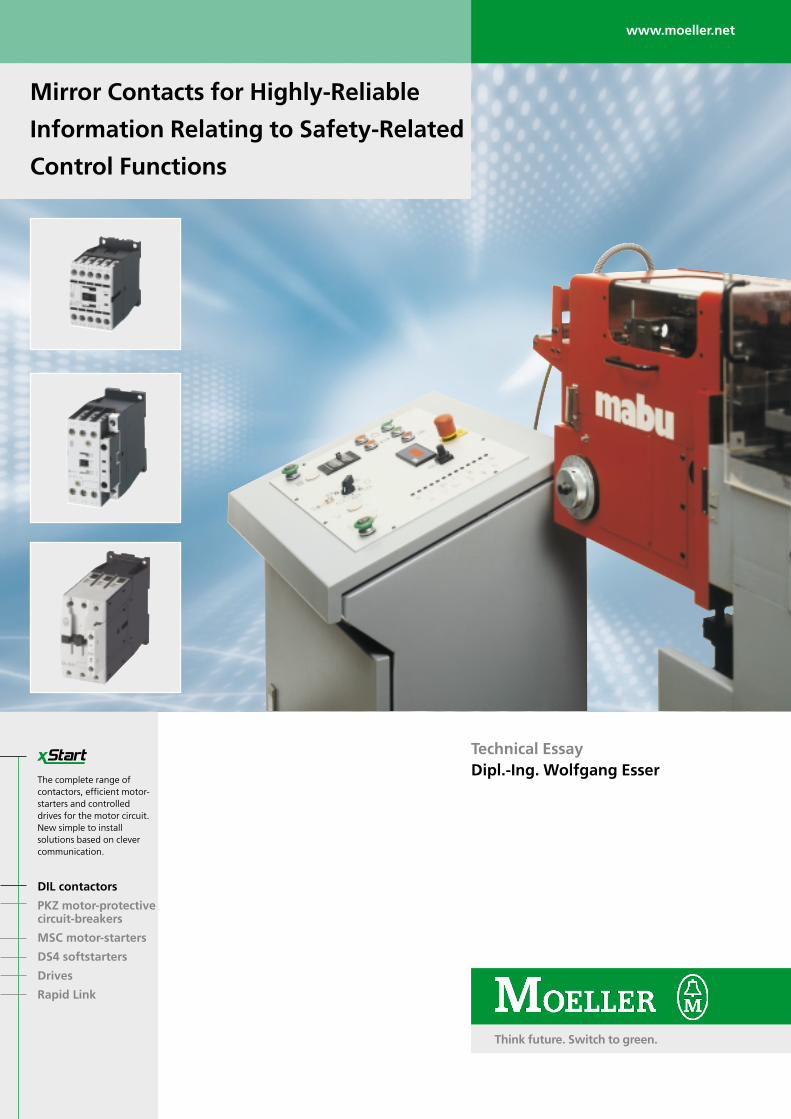
Mirror Contacts for Highly-Reliable
Information Relating to Safety-Related
Control Functions
Technical EssayDipl.-Ing. Wolfgang Esser
DIL contactors
PKZ motor-protectivecircuit-breakers
MSC motor-starters
DS4 softstarters
Drives
Rapid Link
The complete range ofcontactors, efficient motor-starters and controlleddrives for the motor circuit.New simple to installsolutions based on clevercommunication.
2
Summary for fast readers
In the last few years, the significance of safety-related circuits for personnelprotection has become an issue ofwhich there is a general awareness. The issue is not just subject tocontinuous development and review by the German employers liabilityinsurance association, and for example,the SUVA (Swiss accident preventionauthority) in Switzerland, but has also
gained additional recognition andsignificance in safety circuits in theprotection of high-value capitalinvestments and guaranteeing a highlevel of system availability. Thereadiness for use of safety circuits exists,but there is frequently an element ofuncertainty regarding the properties ofcontacts, the interaction of main andauxiliary contacts and the standardised
terms such as “positively-drivencontacts” or the relatively new “mirrorcontact”. Positively-driven contacts”only partly fulfil the expectations of theuser in safety-related circuits. Clarity isachieved by the use of mirror contacts,whose demands are fulfilled by the newDIL M contactors from Moeller. Typicalcontact properties and the definitionwill be presented.
Literature:
[1] IEC / EN 60 204-1 “Electricalequipment of machines, Part 1:General requirements”, non-authorized raw translation fromIEC 60 204-1: 2002 / 44/367/CD(Date 6/2002)
[2] DIN / IEC 62 061 * ClassificationVDE 0113 Part 50, “Safety ofmachinery - Functional safety ofelectrical, electronic andprogrammable control systems formachinery”, draft June 2003
[3] DIN EN ISO 13849-1 (inpreparation) “Safety of machinery- Safety-related parts of controlsystems - Part 1: General principlesfor design” intended as areplacement for: DIN EN 954-1
[4] IEC / EN 60 947-4-1 and DIN VDE0660 Part 102 “Low-voltageswitchgear and controlgear - Part4-1: Electromechanical contactorsand motor-starters”
[5] Dirk Meyer “Switchgear for Powerfactor correction systems”,VER2100-934 Moeller GmbH,2003
[6] DIN EN 60947-5-1 (VDE 0660 Part200):2000-08 “Low-voltageswitchgear and controlgear Part5-1: Control circuit devices andswitching elements;electromechanical control circuitdevices” (IEC 60947-5-1:1997 +A1:1999 + A2:1999), Germanversion EN 60947-5-1:1997 +A12:1999 + A1:1999 + A2:2000
DIN IEC 60947-5-1/A3 “Low-voltage switchgear andcontrolgear Part 5-1: Controlcircuit devices and switchingelements – electromechanicalcontrol circuit devices –amendment 3 to IEC 60947-5-1(1997-10) (IEC 17B/1176/CD:2001)
[7] Wolfgang Esser“Aspects of function safeengineering of contact-relatedcontrol circuits” VER 08+43-787Moeller GmbH, Bonn, 1993
[8] UL 508, “Industrial ControlEquipment”
[9] CSA-C 22.2 No. 14, “IndustrialControl Equipment, IndustrialProducts”
[10] IEC / EN 60 947-1, “Low-voltageswitchgear and controlgear Part 1:General rules”
[11] IEC / EN 60 947-3 and VDE 0660Part 107 “Low-voltage switchgearand controlgear Part 3: “Switches,disconnectors, switch-disconnectors and fuse-combination units”
[12] IEC / EN 60 947-2 and DIN VDE0660 Part 101 “Low-voltageswitchgear and controlgear Part 2:Circuit-breakers
1 Safety-relevant control function: Control function with a determined degree of reliability, which is intended to retain the safe state of the machine and to prevent the emergence of dangerous situations (IEC / EN 60 204-1, draft 2002 [1], in preparation as IEC 62 061 [2] and DIN EN ISO 13849-1 [3]).
Mirror contacts for highly-reliable information relating to safety-related control functions1
- High dependability using newly defined mirror contacts -
3
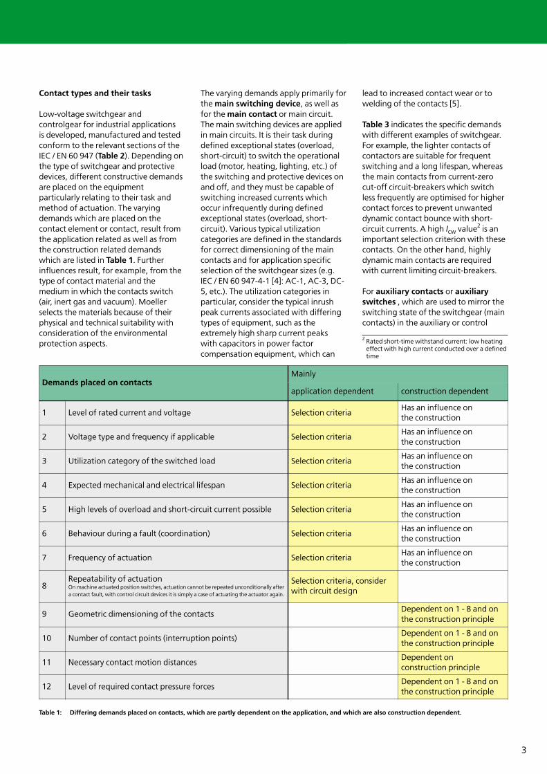
Contact types and their tasks
Low-voltage switchgear andcontrolgear for industrial applications is developed, manufactured and testedconform to the relevant sections of theIEC / EN 60 947 (Table 2). Depending onthe type of switchgear and protectivedevices, different constructive demandsare placed on the equipmentparticularly relating to their task andmethod of actuation. The varyingdemands which are placed on thecontact element or contact, result fromthe application related as well as fromthe construction related demandswhich are listed in Table 1. Furtherinfluences result, for example, from thetype of contact material and themedium in which the contacts switch(air, inert gas and vacuum). Moellerselects the materials because of theirphysical and technical suitability withconsideration of the environmentalprotection aspects.
The varying demands apply primarily forthe main switching device, as well asfor the main contact or main circuit.The main switching devices are appliedin main circuits. It is their task duringdefined exceptional states (overload,short-circuit) to switch the operationalload (motor, heating, lighting, etc.) ofthe switching and protective devices onand off, and they must be capable ofswitching increased currents whichoccur infrequently during definedexceptional states (overload, short-circuit). Various typical utilizationcategories are defined in the standardsfor correct dimensioning of the maincontacts and for application specificselection of the switchgear sizes (e.g.IEC / EN 60 947-4-1 [4]: AC-1, AC-3, DC-5, etc.). The utilization categories inparticular, consider the typical inrushpeak currents associated with differingtypes of equipment, such as theextremely high sharp current peaks with capacitors in power factorcompensation equipment, which can
lead to increased contact wear or towelding of the contacts [5].
Table 3 indicates the specific demandswith different examples of switchgear.For example, the lighter contacts ofcontactors are suitable for frequentswitching and a long lifespan, whereasthe main contacts from current-zerocut-off circuit-breakers which switchless frequently are optimised for highercontact forces to prevent unwanteddynamic contact bounce with short-circuit currents. A high Icw value2 is animportant selection criterion with thesecontacts. On the other hand, highlydynamic main contacts are requiredwith current limiting circuit-breakers.
For auxiliary contacts or auxiliaryswitches , which are used to mirror theswitching state of the switchgear (maincontacts) in the auxiliary or control
Demands placed on contactsMainly
application dependent construction dependent
1 Level of rated current and voltage Selection criteriaHas an influence on the construction
2 Voltage type and frequency if applicable Selection criteriaHas an influence on the construction
3 Utilization category of the switched load Selection criteriaHas an influence on the construction
4 Expected mechanical and electrical lifespan Selection criteriaHas an influence on the construction
5 High levels of overload and short-circuit current possible Selection criteriaHas an influence on the construction
6 Behaviour during a fault (coordination) Selection criteriaHas an influence on the construction
7 Frequency of actuation Selection criteriaHas an influence on the construction
8Repeatability of actuationOn machine actuated position switches, actuation cannot be repeated unconditionally aftera contact fault, with control circuit devices it is simply a case of actuating the actuator again.
Selection criteria, considerwith circuit design
9 Geometric dimensioning of the contactsDependent on 1 - 8 and onthe construction principle
10 Number of contact points (interruption points)Dependent on 1 - 8 and onthe construction principle
11 Necessary contact motion distancesDependent on construction principle
12 Level of required contact pressure forcesDependent on 1 - 8 and onthe construction principle
2 Rated short-time withstand current: low heatingeffect with high current conducted over a definedtime
Table 1: Differing demands placed on contacts, which are partly dependent on the application, and which are also construction dependent.
4
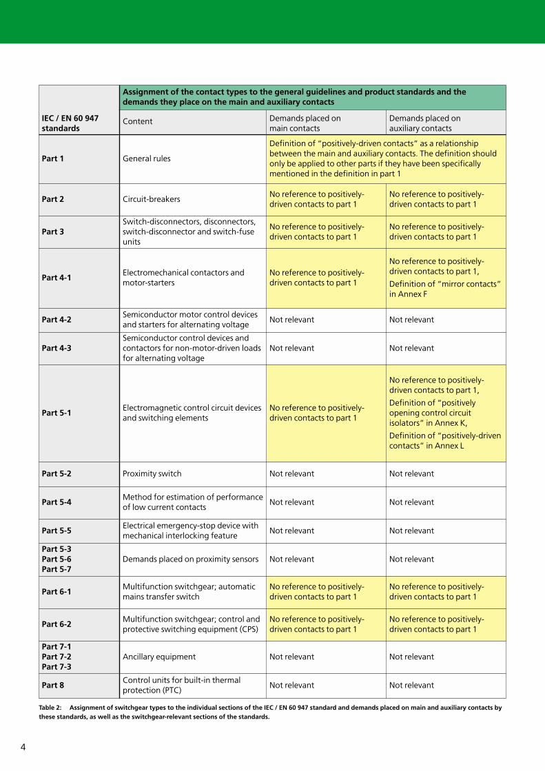
IEC / EN 60 947standards
Assignment of the contact types to the general guidelines and product standards and the demands they place on the main and auxiliary contacts
Content Demands placed on main contacts
Demands placed on auxiliary contacts
Part 1 General rules
Definition of “positively-driven contacts” as a relationship between the main and auxiliary contacts. The definition shouldonly be applied to other parts if they have been specifically mentioned in the definition in part 1
Part 2 Circuit-breakersNo reference to positively-driven contacts to part 1
No reference to positively-driven contacts to part 1
Part 3Switch-disconnectors, disconnectors,switch-disconnector and switch-fuseunits
No reference to positively-driven contacts to part 1
No reference to positively-driven contacts to part 1
Part 4-1Electromechanical contactors andmotor-starters
No reference to positively-driven contacts to part 1
No reference to positively-driven contacts to part 1,
Definition of “mirror contacts”in Annex F
Part 4-2Semiconductor motor control devicesand starters for alternating voltage
Not relevant Not relevant
Part 4-3Semiconductor control devices andcontactors for non-motor-driven loadsfor alternating voltage
Not relevant Not relevant
Part 5-1Electromagnetic control circuit devicesand switching elements
No reference to positively-driven contacts to part 1
No reference to positively-driven contacts to part 1,
Definition of “positively opening control circuit isolators” in Annex K,
Definition of “positively-drivencontacts” in Annex L
Part 5-2 Proximity switch Not relevant Not relevant
Part 5-4Method for estimation of performanceof low current contacts
Not relevant Not relevant
Part 5-5Electrical emergency-stop device withmechanical interlocking feature
Not relevant Not relevant
Part 5-3Part 5-6Part 5-7
Demands placed on proximity sensors Not relevant Not relevant
Part 6-1Multifunction switchgear; automaticmains transfer switch
No reference to positively-driven contacts to part 1
No reference to positively-driven contacts to part 1
Part 6-2Multifunction switchgear; control andprotective switching equipment (CPS)
No reference to positively-driven contacts to part 1
No reference to positively-driven contacts to part 1
Part 7-1Part 7-2Part 7-3
Ancillary equipment Not relevant Not relevant
Part 8Control units for built-in thermal protection (PTC)
Not relevant Not relevant
Table 2: Assignment of switchgear types to the individual sections of the IEC / EN 60 947 standard and demands placed on main and auxiliary contacts bythese standards, as well as the switchgear-relevant sections of the standards.
5
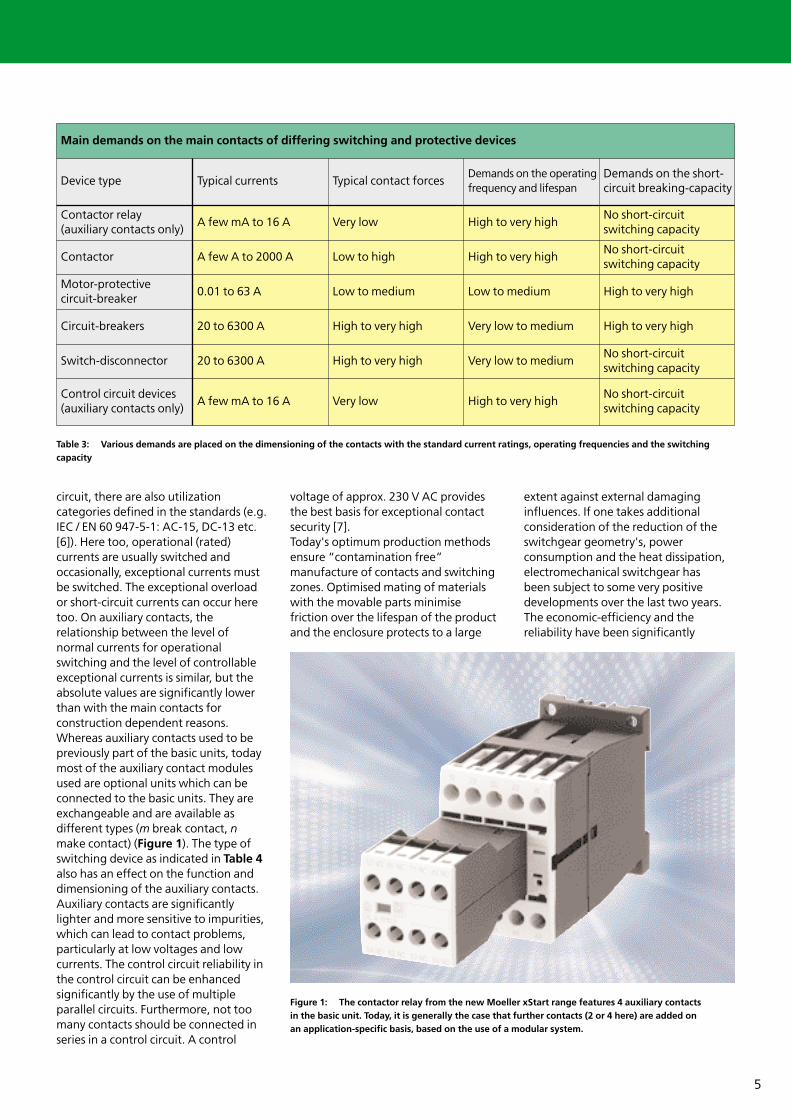
circuit, there are also utilizationcategories defined in the standards (e.g.IEC / EN 60 947-5-1: AC-15, DC-13 etc.[6]). Here too, operational (rated)currents are usually switched andoccasionally, exceptional currents mustbe switched. The exceptional overloador short-circuit currents can occur heretoo. On auxiliary contacts, therelationship between the level ofnormal currents for operationalswitching and the level of controllableexceptional currents is similar, but theabsolute values are significantly lowerthan with the main contacts forconstruction dependent reasons.Whereas auxiliary contacts used to bepreviously part of the basic units, todaymost of the auxiliary contact modulesused are optional units which can beconnected to the basic units. They areexchangeable and are available asdifferent types (m break contact, nmake contact) (Figure 1). The type ofswitching device as indicated in Table 4also has an effect on the function anddimensioning of the auxiliary contacts.Auxiliary contacts are significantlylighter and more sensitive to impurities,which can lead to contact problems,particularly at low voltages and lowcurrents. The control circuit reliability inthe control circuit can be enhancedsignificantly by the use of multipleparallel circuits. Furthermore, not toomany contacts should be connected inseries in a control circuit. A control
voltage of approx. 230 V AC providesthe best basis for exceptional contactsecurity [7]. Today's optimum production methodsensure “contamination free”manufacture of contacts and switchingzones. Optimised mating of materialswith the movable parts minimisefriction over the lifespan of the productand the enclosure protects to a large
extent against external damaginginfluences. If one takes additionalconsideration of the reduction of theswitchgear geometry's, powerconsumption and the heat dissipation,electromechanical switchgear has been subject to some very positivedevelopments over the last two years.The economic-efficiency and thereliability have been significantly
Main demands on the main contacts of differing switching and protective devices
Device type Typical currents Typical contact forcesDemands on the operatingfrequency and lifespan
Demands on the short-circuit breaking-capacity
Contactor relay (auxiliary contacts only)
A few mA to 16 A Very low High to very high No short-circuit switching capacity
Contactor A few A to 2000 A Low to high High to very high No short-circuit switching capacity
Motor-protective circuit-breaker
0.01 to 63 A Low to medium Low to medium High to very high
Circuit-breakers 20 to 6300 A High to very high Very low to medium High to very high
Switch-disconnector 20 to 6300 A High to very high Very low to mediumNo short-circuit switching capacity
Control circuit devices(auxiliary contacts only)
A few mA to 16 A Very low High to very high No short-circuit switching capacity
Table 3: Various demands are placed on the dimensioning of the contacts with the standard current ratings, operating frequencies and the switchingcapacity
Figure 1: The contactor relay from the new Moeller xStart range features 4 auxiliary contacts in the basic unit. Today, it is generally the case that further contacts (2 or 4 here) are added on an application-specific basis, based on the use of a modular system.
6
enhanced. In 1987, the departmenthead for control engineering at Moellerwrote: “The higher-level use ofcontactor relays is practicallyunavoidable with safety-relevantfunctions. A particular example is theuse in the emergency-stop functions onmachines and systems in automation”[7]. This statement remained essentiallycorrect for more than 15 years. The useof mechanical contacts is no longerunavoidable according to the standards,but they are still state-of-the-art inmany fields of application and willcontinue to be a dominant force for the foreseeable future, and inparticular, will retain their veryeconomic position.
Auxiliary contact components ofmodern low-voltage switchgear arevery complex. They earn the title ofuniversal contacts when theirperformance range is closelyconsidered. Originally developed forconventional contactor control circuitswith high voltage and current levels,their construction was improvedsignificantly at the start of the 80's andthey are now equally suited for lowcurrents and voltages. An obviousdivision into special contacts for smalland relatively large powers should beavoided for logistical reasons, in orderto prevent the proliferation of multiple
product series. A division of this natureis also not useful from a technicalapplication point of view, as forexample, on an overload relay the breakcontact (NC) generally switches thecontrol voltage with the high level ofthe contactor control, whereas themake contact (NO) usually transfers thelow current / voltage level for a faultsignal to an electronic control. Thenecessity for switching differingpotentials has practically totallyeliminated the need for changeovercontacts.
Typical good pair values which aremastered are usually 230 V / 6 A and 17 V / 5 mA (rated value 24 V).Following this trend, Moeller hasachieved good control circuit reliabilityat 17 V and currents of just 1 mA. As themodern switchgear devices are devicesfor world markets, they also master the North American “Heavy Duty”characteristic values or the sophisticatedcontacts of the timing and overloadrelay to “Standard Duty” conform to UL508 [8] and CSA-C 22.2 No. 14 [9]. Onsome devices for use in North America,a note stating “600 V, same polarity”must be observed, and it means that theauxiliary contacts of the same auxiliaryswitch or auxiliary contact modulelocated alongside one another must beconnected to the same control voltage
source in order to exhibit the sameelectrical potential.
Insofar as is possible in terms of thephysical and geometric demands on theauxiliary contacts, Moeller uses thesame auxiliary contact module on manyproduct groups and / or device sizes.
Differing demands placed on thereliability of auxiliary contacts
It is not the objective of this essay todescribe the correct constructivedimensioning of contacts, but rather to explain the application-specificdemands to be observed, and isintended to represent the effectivenessof an auxiliary contact switch positionfor safety-relevant use. Briefly: Thisessay is intended to assist withengineering and not withdimensioning.
The task of the auxiliary contact, can forexample, be intended as the control foran indicator light for signalling theswitching state or the operating status.The contacts can also be initiated byfurther switching functions or caninhibit other switching functions as aninterlock contact. In the course of thisessay, the suitability of the auxiliarycontacts for tripping or preventing
Construction features and influences which are to be mastered
Demands on the auxiliary contact with the product groups
Contactor relay Timing relay Contactor Overload relay
DIL A ETR 4, DIL ET DIL M ZB
Actuation method Electromagnetic Electromagnetic Electromagnetic Thermodynamic
Mechanical/electrical lifespan Very high Very high Very high Low
Operating frequency Normal to medium Normal to high Low to normal Very low
Contact force Medium Low Medium to high Very low
Contacts per unit 4, 6, 8 2 changeover contacts
1 ... 8 2
Influences from the basic unitAre part of the basic unit
Are part of the basic unit
ShockShock from the contactor
Mostly subject to environmental factors Normal Normal Normal Normal
Preferred location Control panel Control panel Control panel Control panel
7
further switching is of particularinterest. On safety-related circuits foraccident-prevention and for protectionof capital investment, it is essential to be able to rely on the switch positionof the auxiliary contacts and theirrelationship to the main contacts. Itmust be possible to determine if theload (the equipment) is switched on or off. On critical safety-relevantcircuits, it may be necessary toimplement redundant control currentcircuits3 or the equipment may need tobe monitored by an additional self-acting protection system fitted directlyon the equipment (e.g. zero speedmonitor, speed monitor, or similar). Inaddition to the redundancy, diversity4)may be required [1]. For certainstandard monitoring circuits such as
emergency-stop monitoring,protective door monitoring,switching pad monitoring andtwo-hand control,
Moeller provides special prefabricatedsafety relays of the ESR series. In mostapplications, one usually relies on thereliability of the normal auxiliarycontacts.
If you have not explored the differenttypes of switching devices and theirtypical unique features in great detail, it
is typically assumed that the auxiliarycontacts always assume the same switchposition simultaneously with therespective main contacts. However, this obvious assumption is not alwayspossible to realise, and not just in termsof timing. For example, the linearmotions of the actuators of the mainand auxiliary contacts may vary inlength, so that pretravel path and theslowdown paths leads to differingswitching time points. On early-makecontacts, late-break contacts oroverlapping contacts, the differingswitching points are purposelyintroduced and used for technicalpurposes. Overlapping contacts arerequired for example for interruptionfree switchover operations.
Standard conform “positively-drivencontacts” only partly fulfil theexpectations of the switchgear users
The term “positively-driven contacts”has never actually fulfilled theexpectations of the switchgear users.The user simply expects anunambiguous and reliable statement
concerning the status of the switchedequipment. He would like to use thepositively-driven contact elements, e.g.for safety-relevant self-monitoring onthe machine control circuit. Mostdefinitions of the “positively-drivencontacts” relate exclusively to theauxiliary contacts and only to thecontinuously differing switching stateof break contacts and make contacts.Further limitations of the term will beexplained later. In conjunction withaccident prevention on power operatedpresses in the metal processing field,the term “positively-driven contacts”was defined for press safety controls asone of the first safety-related solutionsin electrical control engineering field.This term was first described by theGerman employer’s liability insuranceassociation guideline ZH 1 / 457.
The term “positively-driven contacts”initially referred to contactor relay andauxiliary contacts only. The positiveopening operation of the auxiliarycontacts ensured over the entirelifespan of the device that the breakcontact and the make contact of adevice could never by closed
3 Redundancy = usage of more than one device (system), to ensure that another function is fulfilled if thedevice (system) malfunctions. Terms: full or partial redundancy, online redundancy, off-lineredundancy
4 Diversity = avoidance of faults and / or malfunctions by the use of differing functional principles:Break contacts and make contacts, components of different construction type,electromechanical and electronic components, electrical and non-electrical systems
Motor-protectivecircuit-breaker
Circuit-breakers Control circuit devices
Position switches
PKZ NZM RMQ 16 /22 AT
Stored energy mechanism
Stored energy mechanism
Manually actuated Machine actuated
High Medium Medium Very high
Low to normal Low Normal to high Low to very high
Low to normal Medium to high Low Medium
1... 6 2, 4, 6 1 ... 6 1, 2, 3
Shock ShockHeat of the indicator light
Are part of the basic unit
Normal to high Normal Normal to high Normal to very high
Control panel, small enclosure
Control panel Small enclosure, on machine
On machine
Table 4: Auxiliary contacts of differentswitching and protection devices are loaded indifferent manners by the basic units and theactual applications. The approximate ratings aremainly true for the main uses of the devices.
8
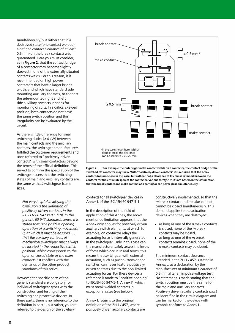
simultaneously, but rather that in adestroyed state (one contact welded), a defined contact clearance of at least0.5 mm (on the break contact) wasguaranteed. Here you must consider, as in Figure 2, that the contact bridgeof a contactor may become slightlyskewed, if one of the externally situatedcontacts welds. For this reason, it isrecommended on high powercontactors that have a larger bridgewidth, and which have standard sidemounting auxiliary contacts, to connectthe side-mounted right and left side auxiliary contacts in series formonitoring circuits. In a critical skewedposition, both contacts do not have the same switch position and thisirregularity can be evaluated by thecircuit.
As there is little difference for smallswitching duties (< 4 kW) between the main contacts and the auxiliarycontacts, the switchgear manufacturersfulfilled the customer requirements andsoon referred to “positively-drivencontacts” with small contactors beyondthe terms of the official definition. Thisserved to confirm the speculation of theswitchgear users that the switchingstates of main and auxiliary contacts arethe same with all switchgear framesizes.
Not very helpful in allaying theconfusion is the definition ofpositively-driven contacts in the IEC / EN 60 947 Part 1 [10]. In thisgeneric 60 947 standards series, it isstated that “the positive openingoperation of a switching movementis, at which it must be ensured ... ,that the auxiliary contacts ofmechanical switchgear must alwaysbe located in the respective switchposition, which corresponds to theopen or closed state of the maincontacts.” It conflicts with thedemands of the other productstandards of this series.
However, the specific parts of thegeneric standard are obligatory forindividual switchgear types with theconstruction and testing of theswitching and protective devices. Inthese parts, there is no reference to thedefinition in part 1, but rather, you arereferred to the design of the auxiliary
contacts for all switchgear devices inAnnex L of the IEC / EN 60 947-5-1.
In the description of the field ofapplication of this Annex, the abovementioned limitation appears, that theAnnex only applies for positively drivenauxiliary switch elements, at which forexample, on contactor relays theactuating force is internally generatedin the switchgear. Only in this case canthe manufacturer safely assess the levelsof force which occur. In real terms, thismeans that switchgear with externalactuation, such as pushbuttons or endswitches, can never feature positively-driven contacts due to the non-limitedactuating forces. For these devices areference is made to “positive opening”to IEC/EN 60 947-5-1, Annex K, whichmust break welded contacts inexceptional cases (see below).
Annex L returns to the originaldefinition of the ZH 1 / 457, wherepositively driven auxiliary contacts are
constructively implemented, so that them break contact and n make contactcannot be closed simultaneously. Thisdemand applies to the actuationdevices when they are destroyed:
as long as one of the n make contactsis closed, none of the m breakcontacts may be closed,as long as one of the m breakcontacts remains closed, none of then make contacts may be closed.
The minimum contact clearanceintended in the ZH 1 / 457 is stated inAnnex L, as a declaration by themanufacturer of minimum clearance of0.5 mm after an impulse voltage test.No statement is made stating that theswitch position must be the same forthe main and auxiliary contacts.Positively driven auxiliary contacts mustbe identified in the circuit diagram andcan be marked on the device withsymbols conform to Annex L.
→
→
≥ 0,5 mm
→
→≥ 0,5 mm*
Öffner
Öffner
Schließer
Schließer
*im hier gezeigten Fall, bei einer Doppelunterbrechung, kann die Strecke geteilt werden, in 2 x 0,25 mm.
Figure 2: If for example the outer right make contact welds on a contactor, the contact bridge of theswitched off contactor may skew. With “positively-driven contacts” it is required that the breakcontact does not close in this case, but rather, that a clearance of 0.5 mm is retained between thecontacts for the entire lifespan of the contactor. Various safety circuits are based on the assumptionthat the break contact and make contact of a contactor can never close simultaneously.
break contact
break contact
*in the case shown here, with adouble-break the clearancecan be split into 2 x 0.25 mm.
make contact
≥ 0.5 mm
≥ 0.5 mm*
make contact
9
Clarity with the newly defined mirrorcontacts
Mirror contacts are constructed andtested conform to IEC / EN 60 947-4-1[4], Annex F. By definition, a mirrorcontact must always be an auxiliarybreak contact. A contactor may featuremultiple mirror contacts. Switchgearwithout auxiliary break contacts cannever feature mirror contacts accordingto the definition. The contacts that aremirrored are the main circuit makecontacts. As a result, a contactor relaycan never feature mirror contactsbecause it does not have main contacts.
At the current time, mirror contacts arecurrently known exclusively when usedwith contactors. As long as any maincontact of a contactor is closed, amirror contact (auxiliary break contact)may not be closed. This definition alsoapplies when the contactor is notsupplied with actuating voltage.Sufficient contact clearance of 0.5 mmis guaranteed by the manufacturer onthe mirror contact, during a simulatedwelding of a main contact by animpulse voltage test. This test must besuccessfully passed after the end of theperformance test.
A typical application for mirror contactsis to implement very reliable monitoringof the switched state of a contactor in
machine control circuits. On the otherhand, the standard emphasises that it isnot prudent to rely exclusively on mirrorcontacts as a safety device, and itrecommends self-monitoring of themirror contact circuit.
The definition of mirror contacts canonly contribute, due to the constructionconditions, to the relationship betweenthe main circuit make contact and theauxiliary break contact. Theseconstruction related conditions arejustified by the fact that the maincontacts and the auxiliary contactsalmost always have their own contactbridges, and that the forces acting onthe main and auxiliary contacts are of adifferent magnitude. It is not simplypossible to demand, that a weldedauxiliary contact of an energisedcontactor should act on the maincontacts of a heavy switching dutycontactor, and keep it in the switchedon position.
More exact information throughpositively driven mirror contacts
Annex F of IEC / EN 60 947-4-1 [4]allows the use of mirror contacts inaddition to the demands on positively-driven contacts, to Annex L of IEC / EN60 947-5-1. The term from the header“positively driven mirror contacts”
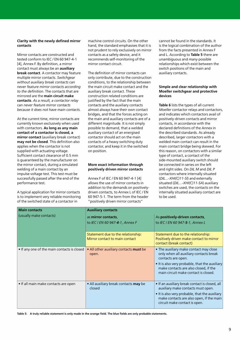
cannot be found in the standards. It is the logical combination of the authorfrom the facts presented in Annex F and L. According to Table 5 there areunambiguous and many possiblerelationships which exist between theswitch positions of the main andauxiliary contacts.
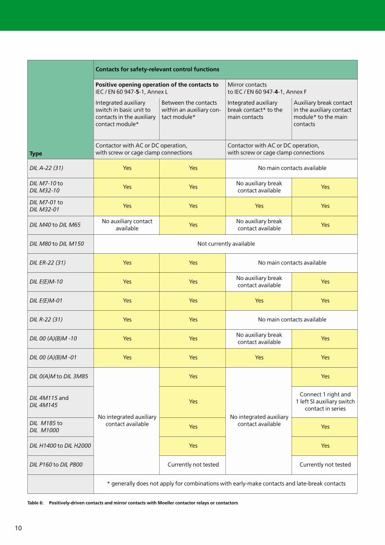
Simple and clear relationship withMoeller switchgear and protectivedevices
Table 6 lists the types of all currentMoeller contactor relays and contactors,and indicates which contactors avail ofpositively-driven contacts and mirrorcontacts, in accordance with thedeclared definitions of the Annex in the described standards. As alreadydescribed, larger contactors with awelded main contact can result in themain contact bridge being skewed. Forthis reason, on contactors with a similartype of contact, a contact of the side-mounted auxiliary switch should be connected in series on the left and right sides. On DIL M and DIL Pcontactors where internally situated(DIL...-XHI(C)11-SI) and externallysituated (DIL...-XHI(C)11-SA) auxiliaryswitches are used, the contacts on theinternally situated auxiliary contact areto be used.
Main contacts
(usually make contacts)
Auxiliary contacts
as mirror contacts,
to IEC / EN 60 947-4-1, Annex F
As positively-driven contacts,
to IEC / EN 60 947-5-1, Annex L
Statement due to the relationship: Mirror contact to main contact
Statement due to the relationship: Positively driven make contact to mirrorcontact (break contact)
• If any one of the main contacts is closed • All other auxiliary contacts must beopen.
• The auxiliary make contact may closeonly when all auxiliary contacts breakcontacts are open.
• It is also very probable, that the auxiliarymake contacts are also closed, if themain circuit make contact is closed.
• If all main make contacts are open • All auxiliary break contacts may be closed
• If an auxiliary break contact is closed, allauxiliary make contacts must open.
• It is also very probable, that the auxiliarymake contacts are also open, if the maincircuit make contact is open.
Table 5: A truly reliable statement is only made in the orange field. The blue fields are only probable statements.
10
Type
Contacts for safety-relevant control functions
Positive opening operation of the contacts toIEC / EN 60 947-5-1, Annex L
Mirror contacts to IEC / EN 60 947-4-1, Annex F
Integrated auxiliaryswitch in basic unit tocontacts in the auxiliarycontact module*
Between the contactswithin an auxiliary con-tact module*
Integrated auxiliarybreak contact* to themain contacts
Auxiliary break contactin the auxiliary contactmodule* to the maincontacts
Contactor with AC or DC operation, with screw or cage clamp connections
Contactor with AC or DC operation, with screw or cage clamp connections
DIL A-22 (31) Yes Yes No main contacts available
DIL M7-10 toDIL M32-10
Yes YesNo auxiliary break contact available
Yes
DIL M7-01 toDIL M32-01
Yes Yes Yes Yes
DIL M40 to DIL M65No auxiliary contact
availableYes
No auxiliary break contact available
Yes
DIL M80 to DIL M150 Not currently available
DIL ER-22 (31) Yes Yes No main contacts available
DIL E(E)M-10 Yes YesNo auxiliary break contact available
Yes
DIL E(E)M-01 Yes Yes Yes Yes
DIL R-22 (31) Yes Yes No main contacts available
DIL 00 (A)(B)M -10 Yes YesNo auxiliary break contact available
Yes
DIL 00 (A)(B)M -01 Yes Yes Yes Yes
DIL 0(A)M to DIL 3M85
No integrated auxiliarycontact available
Yes
No integrated auxiliarycontact available
Yes
DIL 4M115 andDIL 4M145
YesConnect 1 right and
1 left SI auxiliary switchcontact in series
DIL M185 toDIL M1000
Yes Yes
DIL H1400 to DIL H2000 Yes Yes
DIL P160 to DIL P800 Currently not tested Currently not tested
* generally does not apply for combinations with early-make contacts and late-break contacts
Table 6: Positively-driven contacts and mirror contacts with Moeller contactor relays or contactors
11
Similar terms which are open toconfusion
Contacts with positive opening orpositive operation are frequentlyconfused with positively-drivencontacts. As the term mirror contact isrelatively new, uncertainty exists amongthe users. There is a risk of confusionwith the following, similar terms:
Safe isolationA safe isolation is achieved forexample by insulation, which fulfilshigher demands than the basicinsulation. It is achieved byreinforced or double insulation. Safe isolation is demanded with the generation of a protective extralow voltage (PELV), with safetytransformers between the primaryand secondary windings andbetween all active parts of PELV lowvoltage circuits and other circuits(with dangerous touch voltages). For details see IEC / EN 60 947-1, Annex N.
Protective separation safetymeasure of an individual circuit toIEC / EN 60 364-4-41, for protectionagainst electrical shock (protectionwith indirect touch). Theseprotective measures preventdangerous touch voltages fromcontact with bodies (enclosure,inactive parts), which assume thevoltage of the active part after afault in the basic insulation.
Potential isolation (galvanic isolation)Separation of electrical potentials.There are no conductive connectionsbetween the different circuits. Apotential isolation can be achievedusing certain transformers, withbatteries or different generators,where the voltages are notconnected to one another.Optocouplers are used for example,to protect electronic circuits fromdestruction by higher voltages.Interface elements perform similartasks between control and loadcircuits.
Isolating function / isolating characteristicsA function for shutting down thepower supply to the entire system or
part of a system, whereby the systemor system section is disconnected forall electrical energy sources forsafety reasons. Indication of theposition of the main contacts mustbe unambiguous and effective. The isolating device must havean interlock feature for the off(isolated) position to IEC / EN 60 204-1. According to IEC / EN 60 947-3 [9],enhanced demands are placed onthe tenacity of the operatingelements, in order to prevent thatthe operating element can beswitched to the off position when aswitch has welded.
Isolating gap, visible isolating gapClearance between the opencontacts or the conductive parts of a pole of mechanical switchgearconnected to them in the openposition, which fulfils the stipulatedsafety requirements for adisconnector. It is demanded to IEC / EN 60 204-1:2002 for powerdisconnecting devices (mainswitches). If the isolating gap is notvisible, the off position may not beindicated using a switch positionindication, before all (main) contactsare actually open and a sufficientisolating gap conform to IEC / EN 60947-3 [11] exists between allcontacts.
Positive opening (of a contact) (notto be confused with positiveopening operation!) To IEC / EN 60204-1:2002 and IEC / EN 60 947-5-1,Annex K; positive opening is definedas the assurance of contactseparation as a direct result of adefined motion of an operating unitof the switch via non spring parts(e.g. not dependant on a spring foroperation). This feature is demandedto IEC / EN 60 204-1:2002, forexample with emergency-stopdevices. Every control circuit isolatorwith positive opening must bepermanently externally marked onthe outer side with a legiblestandard symbol.Also in regard to positive opening,there is a definition in the IEC / EN 60947-1 which refers to the position ofthe main contacts. In this definition,the switch-specific parts of the IEC /EN 60 947 is also not referred to.
Positive opening clearanceMinimum clearance fromcommencement of the actuation ofthe operating unit until the positionin which the positive opening of thecontact to be opened has ended.
Inevitable effectConnection between the operatingunit and the contact, which transfersthe force applied to the operatingunit directly to the contact (IEC / EN 60 947-5-1).
Non-inevitable effectConnection between the operatingunit and the contact, which limitsthe force applied to the operatingunit (IEC / EN 60 947-5-1).
Think future. Switch to green.
Moeller addresses worldwide:www.moeller.net/addressE-Mail: [email protected]
© 2004 by Moeller GmbHSubject to alterationsVER2100-944GB MDS/xx 10/04 Printed in the Federal Republic of Germany (10/04)Article No.: 286821
Xtra Combinations
Xtra Combinations from Moeller offers a range of productsand services, enabling the best possible combination optionsfor switching, protection and control in power distributionand automation.
Using Xtra Combinations enables you to find more efficientsolutions for your tasks while optimising the economic viability of your machines and systems.
It provides:■ flexibility and simplicity■ great system availability■ the highest level of safety
All the products can be easily combined with one another mechanically, electrically and digitally, enabling you to arriveat flexible and stylish solutions tailored to your application –quickly, efficiently and cost-effectively. The products are proven and of such excellent quality thatthey ensure a high level of operational continuity, allowingyou to achieve optimum safety for your personnel, machinery,installations and buildings.
Thanks to our state-of-the-art logistics operation, our com-prehensive dealer network and our highly motivated servicepersonnel in 80 countries around the world, you can count on Moeller and our products every time. Challenge us! We are looking forward to it!