Embed Size (px)
Citation preview
Multi–object handling for robotic manufacturingMirko Ferrati, Simone Nardi, Alessandro Settimi, Hamal Marino, Lucia Pallottino
Abstract—The purpose of this work is to move a step towardthe automation of industrial plants through full exploitation ofautonomous robots. A planning algorithm is proposed to movedifferent objects in desired configurations with heterogeneousrobots such as manipulators, mobile robots and conveyor belts.The proposed approach allows different objects to be handledby different robots simultaneously in an efficient way and avoid-ing collisions with the environment and self–collisions betweenrobots. In particular, the integrated system will be capableof planning paths for a set of objects from various startingpoints in the environment (e.g. shelves) to their respective finaldestinations. The proposed approach unifies the active (e.g.,grasping by a hand) and passive (e.g., holding by a table)steps involved in moving the objects in the environment bytreating them as end–effectors with constraints and capabilities.Time varying graphs will be introduced to model the problemfor simultaneous handling of objects by different end–effectors.Optimal exploration of such graphs will be used to determinepaths for each object with time constraints. Results will bevalidated through simulations.
Index Terms—Robotics, Intelligent Robots, Factory Automa-tion, Manufacturing Automation, Motion Control
I. INTRODUCTION
The upward trend of industrial processes automation andthe advent of smart factories in the context of the fourthindustrial revolution rely on the complete and easy integrationof autonomous robots in complex environments.
Such robots may differ in shape and capabilities, but shouldwork together in a highly dynamic assembly chain, where thechain itself requires a continuous reconfiguration based on dif-ferent typologies of processed item. Moreover, in applicationswhere objects cannot have a standardized shape, or in complexend–of–lines setups that require a particular orientation ofthe items, a completely integrated and autonomous solutionis missing. Two examples of such dynamic environments arethe online shopping warehouses of Amazon [1] and Ocado [2]where products are moved by autonomous mobile shelves orby a complex system of conveyor belts. However, in bothcases, the final manipulation of objects is still handled byhumans at the end of the line. Both companies are researchinga way to completely automate the process, see for examplethe Amazon Picking Challenge [3]. Our aim is to propose aunified framework where a set of heterogeneous manipulatorsand mobile robots are managed autonomously in order to pick,move, grasp and manipulate different products. Moreover, theframework should take into account objects of arbitrary shapeand manipulators of different grasping capabilities. Indeed, inthis case, new robot typology can be added to the system withsmall effort (e.g. a change of a configuration database).
All authors are with Centro di Ricerca “E. Piaggio”, University ofPisa, 56122 Pisa, Italy. A. Settimi is also with the Dept. of AdvancedRobotics, Istituto Italiano di Tecnologia, via Morego, 30, 16163 Genova.L. Pallottino is also with the Dept. of Information Engineering,University of Pisa, 56122 Pisa, Italy. ([email protected],[email protected], [email protected],[email protected], [email protected])
Fig. 1. An example industrial–like scenario. Multiple object have to be carriedacross a factory, robotic arms are used to arrange the objects on availablemobile robots and on workbenches.
The integration of the proposed framework within a smart-factory could be done through a management system, in-tegrated with the online shopping software, that schedulesrequests for the warehouses robots to handle the queue ofcustomer orders. An example of this management system canbe found in [4].
Recent research on smart-factories automated planners fo-cuses on solutions to automatize specific industrial scenarios.Such works do not ensure adaptability to an already existingstructured environment: on the contrary, they are usually de-signed ad–hoc on the final application scenario. For example,in [5] and [6] the proposed approaches rely on a substantialplant reconfiguration or design.
A complete framework for task assignment, planning andcoordination of multiple mobile robots is described in [7],where the capability of integrating the system in existing en-vironments is obtained. However, this work does not considerthe integration with assembly lines or more generic manipu-lation of objects (e.g. placing items into shipping boxes), butrather considers only the planning of movement of goods. Amixed cooperation between mobile robots and robotic arms inmanufacturing scenarios with multiple objects is shown in [8]and [9], even if limited to a single manufacturing cell. Webelieve that it is fundamental to realize solutions that are adapt-able to different industrial scenarios. Indeed, this would allowto deploy standard robots in existing structured environmentswithout modifying them. At the same time, we aim for anintegrated mobile/manipulator system able to handle multipleobjects simultaneously and a dynamic assembly chain, as theprevious cited Amazon and Ocado cases.
For this purpose, we developed an integrated system capableof planning the paths of a sequence of objects from variousstarting points in the environment (e.g. shelves) to theirrespective final destinations. Multiple robotics hardware maybe required to perform the objects motion or to manipulateobjects such as manipulators, hands and mobile robots. Forexample, in Fig. 1 an industrial–like scenario is represented

where multiple objects are grasped by a robotic arm, oneafter another. The objects are then brought by one of theavailable mobile robots to the other robotic arm to be placed onanother workbench. This can be associated to an intermediatephase of a manufacturing process. Our approach unifies allthe active and passive steps involved in the objects motiontreating them as end–effectors. The object path is plannedconsidering each end–effector constraints and capabilities.Moreover, the returned plan will avoid collisions with theenvironment and self–collisions between robots. The proposedcontribution can be summarized in two main results. First, wepropose an extension of our previous results from [10], inwhich single object moving has been investigated and tested,both in real experiments and simulations scenarios such as anassembly chain with five Kuka arms. In the aforementionedsimulations and experiments, different kinds of object handlinghave been tested, such as: pick-and-place, handoff betweentwo robotic arms, use of a support surface to re-orient theobject. Moreover different objects have been used, includingboth simple geometries such as a ball and a cylinder, andcomplex ones such as a colander and a pitcher.
The extension presented here consists in a modelization offloating base robots, such as mobile manipulators, that com-plies with the end–effector concept in [10]. Such modelizationallows the inclusion of mobile manipulators in planning pathsfor the single object case. Second, we introduce a new plannercapable of managing a queue of multiple different objectsalong the assembly chain at the same time by using a timevarying graph as defined in [11]. Such graphs are used in trafficflow optimization algorithms to compute the shortest time pathof multiple items that are simultaneously crossing a network:indeed, our modelization generates a network from the set ofend–effectors and our planner optimizes the flow of objectsusing shortest time search. Finally the proposed approach isvalidated through a set of simulations with different numbersof end–effectors and objects.
II. EXTENSION TO SYSTEM MODELING
Similarly to [10], in this work each entity that is able toact/apply a grasp/support on an object is considered an end–effector, see Fig. 2 for different examples of end-effectors. Onthe other hand, the relative configuration between the end–effector and a specific grasped object is a grasp. Finally,workspaces are sub-regions of the environment where anobject can be grasped by two or more end–effectors. Forexample in Fig. 3a), the classical workspace is reported inred, yellow and green for the right, both right and left, and leftarms respectively. With the proposed approach the workspaceis represented by the three regions on the table reported inFig. 3b). For example in w2 an object can be grasped by theleft hand if it lays on the table (i.e., grasped by the end-effectorassociated to the table) or if it is grasped by the right hand.
It is possible to distinguish between movable end–effectors(such as serial manipulator end–effector) and non–movableones (such as a surface in the environment providing stableobject support). The difference between such end–effectors isthat the absolute position of an object handled by a movableend–effectors can be changed without changing grasp.
It is worth noting that from a planning perspective, itis not necessary to distinguish between movable and non–movable end–effectors, because they can both interact withan object with their own set of grasps and they can exchange
a b
c d
Fig. 2. In these figures different types of end–effectors and grasps arereported, the blue cylinder is the object considered for grasping. (a) Kuka LWRrobotic arm, movable end–effector. (b) Table, non–movable end–effector. (c)Conveyor belt, movable end–effector. (d) Mobile robot, movable end–effector.
Fig. 3. (a) Considering a dual–arm setup the reachable regions of the leftand right arm are respectively reported in green and red, while the one ofthe table is represented by the table itself. (b) Using the intersection betweensimple approximations of these regions (cuboids), we defined the workspacesfor this scenario.
objects through a set of interaction transitions. For more detailsand examples on the concepts introduced above please referto [10].
A. Mobile robots as movable end–effectorsIn this work the concept of end–effector is extended to
mobile robots that can be seen as movable end–effectors witha floating base. These robots can be considered equipped witheither a grasping device or a simple flat surface, that providesmultiple ways to grasp an object, in the sense defined above.Mobile robots are hence compliant with the end–effectordefinition, and their grasps are the ways they can carry aroundan object. The exchanging workspaces between mobile robotsand other end–effectors are obtained by intersection betweenthe collision–free configuration space of the mobile robotsand the workspace of other end–effectors (see, for example,Fig. 4). Note that, depending on the grasp capabilities, end–effectors do not necessarily share a workspace. For example, amobile robot with a surface does not share the table workspacewhile it does with a fixed base manipulator. Similarly, if themobile robot is equipped with a manipulator it can exchangean object with the table, i.e, the end–effectors share a commonworkspace.
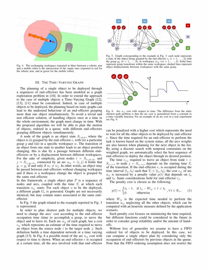
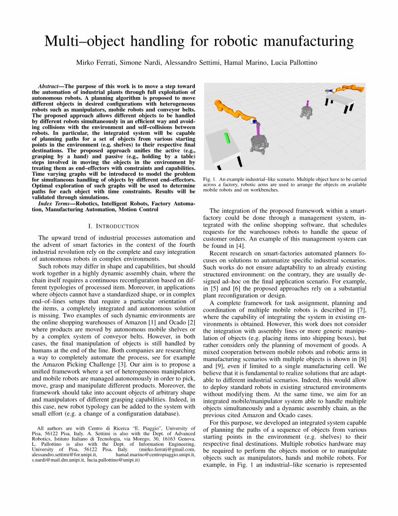
Fig. 4. The exchanging workspace (reported in blue) between a robotic armand a mobile robot is the intersection of the single ones (reported in red forthe robotic arm, and in green for the mobile robot).
III. THE TIME–VARYING GRAPH
The planning of a single object to be deployed througha sequences of end–effectors has been modeled as a graphexploration problem in [10]. In order to extend the approachto the case of multiple objects a Time–Varying Graph [12],[13], [11] must be considered. Indeed, in case of multipleobjects to be deployed, the planning based on static graphs canlead to the undesired behaviour of an end–effector graspingmore than one object simultaneously. To avoid a trivial andnon efficient solution, of handling objects once at a time inthe whole environment, the graph must change in time. Withthe proposed algorithm we will be able to plan the motionof objects, ordered in a queue, with different end–effectorsgrasping different objects simultaneously.
A node of the graph is an object state Se,g,w, where theobject is (i) grasped by the end–effector e, with (ii) a particulargrasp g and (iii) in a specific workspace w. The transition ofan object from one state to another leads to an object positionchanging, this is due by a passage between different end–effectors or by a displacement between different workspaces.For the sake of simplicity, given nodes i = Sei,gi,wi
andj = Sej ,gj ,wj connected by an arc aij = (i, j) it holds thatgi = gj if and only if wi 6= wj . In other words, an object maybe passed between end–effectors without changing workspaceand if there is a workspace change the object is grasped bythe same end–effector.In this framework, a single object plan P is a sequence ofnodes and arcs, coupled with the time Ti at which eachtransition aij starts. For each object o to be the deployed,a different graph Go is generated. Graphs are not necessarilyidentical, but may contain states associated to the same end–effector.
In Fig. 5 the graph related to the example reported in Fig. 3is represented.
In order to plan shortest path for multiple objects, weneed to change the arcs’ cost according to the end–effectoroccupation time (time to accomplish a grasp, to move theobject and to leave it). Each arc aij of each graph, has a costcij which represents an estimate of the time required to movean object from the source node i to the target node j. Suchdefinition builds a time dependent network or a time varyinggraph [13]. In Fig. 6 a possible trend of the arc aij cost withrespect to time is shown. When an end–effector e is occupiedat a certain time, all the arcs involved with that end–effector
Fig. 5. Graph corresponding to the example in Fig. 3: each node representsa state of the object being grasped by the end effector ei (i = 1, . . . , 3) withthe grasp gk (k = 1, . . . , 9), in workspace wm (m = 1, . . . , 3). Solid linesrepresent grasp transitions within the same workspace; dashed lines representobject displacements between workspaces with the same grasp.
g7
g9
g8
g1 g3 g2
aij
cij
t
Fig. 6. Arc aij cost with respect to time. The difference from the staticshortest–path problem is that the arc cost is generalized from a constant toa time–variable function. For an example of an arc cost in a real experimentsee Fig. 9.
can be penalized with a higher cost which represents the needto wait for all the other objects to be deployed by end–effectore. Since the time required for an end–effector to perform thetask is known based on the system status, all the arcs weightsare also known when planning for the next object in the list.By using a discrete search with temporal constraints on theweighted graph, we automatically select the best sequence ofend–effectors to deploy the object through its desired position.
The time ci,j required to move an object from node i =Sei,∗,∗ to node j = Sej ,∗,∗ depends on the starting time Tiof the transition. If the end–effector ei is occupied during thetime interval [ta, tb] such that Ti ∈ [ta, tb], the cost cij of arcaij is increased by a penalty value p(t) that depends on taand tb. Same considerations hold for end–effector ej .
The penalty cost is chosen as the following:
p(t) =
{tb − t, if ta −Wij < t < tb0, otherwise
,∀ t ∈ R+. (1)
where Wij is the expected time needed to perform thetransition aij neglecting all the other objects, which can becomputed with an heuristic measure defined by the applicationscenario.
Such penalty cost focuses on minimizing the time required,but different functions could be considered in the future inorder to consider grasp reliability and/or the amount of hand–offs.
Without loss of generality we assume to have a FIFOordered list of objects to be deployed. In this case, wecan compute a single object plan by considering only theoccupation of end–effectors by previous objects in the queue.Note that the FIFO ordering assumption does not restrict the
proposed approach validity. Indeed, the theorem presentedin [14] allows to turn any non–ordered problem into a FIFOone (in polynomial time) if waiting on nodes is allowed, as inour case.
In the following sections we will first describe the planningalgorithm for a single object and then we extend it to themultiple objects case.
IV. SINGLE OBJECT ALGORITHM
The planning algorithm for a single object moved bymultiple end–effectors proposed in [10] is now briefly reportedfor reader convenience. With respect to the original algorithm,modifications are proposed to adapt it to handle time varyinggraphs. Given the set of plans obtained for prior objectsin the list and given initial and desired object position, theoutcome of the algorithm is a plan for the current object thatis compatible with all the other plans.
An important concept described in details in [10] is theconversion between a path in the object graph and a set ofcommands in Cartesian space that are given to each end–effector. As an example, an arc that represents a change ofworkspace is translated into two Cartesian end-effector poses,respectively in the source and target workspace.
We define with:• CInit, and CFinal the initial and final object configurations
in the Cartesian space,• TInit the initial time of the object plan,• G the time varying graph,• PC the Cartesian plan,• SInit= Sei,gi,wi
and SFinal= Sej ,gj ,wjthe initial and final
object configurations in the graph,• PHL the timed plan on the graph,• ArcId the identity of the arc that makes the Cartesian
planning fail.The algorithm consists of several functions that are briefly
described next:• GetInformationFromDB: all the information the planner
needs are loaded from a database, these informationinclude the end–effectors, the grasp sets for each of themand the workspaces;
• GenerateTimeVaryingGraph: the retrieved information,along with previous objects plans, is used to create thetime varying graph through the time–based arc costspenalization;
• CartesianToGraph: this function translates a Cartesianpositions C into a state S of the graph;
• ShortestTimePath: time-dependent A* is used to find theshortest path (in terms of time execution) in the graphfrom SInit to SFinal;
• GraphToCartesian: kinematic utilities are used to converteach arc in the graph plan to low–level commands suchas move or grasp/ungrasp;
• GetFailedConversion: in case the GraphToCartesian func-tion returns a failure due to a collision with the environ-ment the arc that leads to a collision is returned;
• Backtracking: a backtracking procedure is performedwhenever a collision–free path for a robot cannot befound. In this case the graph is accordingly updated byremoving the arc returned by the GetFailedConversionfunction. The shortest path is thus computed on theupdated graph.
Algorithm 1: Single Object PlanData: Initial and final object position CInit, CFinal,
starting time TInit, Object o, Queue of otherobjects plans P
Result: Plan for object o(states,transitions) = GetInformationFromDB(o);G= GenerateTimeVaryingGraph(states,transitions,P);GHL= G;SInit= CartesianToGraph(CInit);SFinal= CartesianToGraph(CFinal);repeat
PHL= ShortestTimePath(GHL,SInit,TInit,SFinal);if PHL is empty then
Return p not valid;endPC= GraphToCartesian(PHL);if PC is empty then
ArcId= GetFailedConversion();GHL= Backtracking(GHL,ArcId);
enduntil PC is not empty;
Such hypothesis is supported by the fact that in the multi–object scenario (see next Section, for details) the planning isorganized in a FirstInFirstOut approach.
The single object planning problem can be solved byapplying a time–varying graph (TVG) search algorithm, suchas [12], [14], [15] or time varying A*, as described in [16].The TVG search algorithm implemented here is time varyingA*, because, thanks to simple arc cost functions, we do notexperienced a particular performance hit. For future develop-ments, the use of a more performing algorithms such as [17]will be evaluated. The A* solver, in our algorithm, is reportedas ShortestTimePath(graph, start state, start time, end state)function in Algorithm 1.
Note that the introduction of mobile robots does not affectthe graph exploration algorithm at all, while the conversionbetween graph plan and Cartesian positions, performed bythe GraphToCartesian function, require a different inversekinematic algorithm.
V. MULTI-OBJECT SERIAL PLANNING
As reported in previous Section, occupied end–effectors areused to generate time dependent arc costs. Consequently, theplanner chooses objects paths considering parallel paths in thegraph, searching for the shortest time one.
Since we are assuming an ordered queue of objects, we usea FIFO approach when planning for multiple objects. Thus,for each object oi in the queue, we can safely ignore the restof the queue oj , j > i, and consider only the timed paths ofobjects oj with j < i.
The multi–object planner is composed of two main parts:a loop that generates a timed plan for each object in thequeue through Algorithm 1, and a parallel motion planningwhere the Cartesian commands are used to generate jointspace collision free trajectories for each end–effector as shownin next Subsection. Once the first part has generated theset of Cartesian plans P , those plans are reordered by thestarting time of each transition and merged into a sequence ofCartesian commands χ.

Algorithm 2: Global high level planning and executionData: Queue of objects o ∈ O, with their initial and final
positions CInito ,CFinalo and starting time TInitoinitialization;P=empty;while O is not empty do
o = select next object from O;p=plan single object(CInito ,TInito ,CFinalo ,o,P);if p is valid then
add p to P;else
Even in infinite time, the object cannot be moved;Skip object;
endendχ = reorder and merge plans(P);foreach Cartesian command in χ do
plan low-level parallel motions and execute;if Failure in motion planning then
/*Local replan*/Plan motions with different grasps but same
end–effectors;if Failure in motion planning then
/* Global replan*/restart algorithm with CInito = current objectpositions;
endchange motion plan and continue execution;
endend
After the path reordering joint space trajectories are gen-erated taking into account that low level failures can occurwhen single end–effector motion planning fails due to collisionalong the planned trajectory. Usually a simple local re–planthat involves the same end–effectors is enough to solve theproblem, but if the new plan involves changes in the timingsor in the end–effectors involved in subsequent object handling,a global re-plan is required. In case of such failures affectingthe global plan, Algorithm 2 can be re-initialized with thecurrent objects positions as the initial states. Indeed, with theproposed approach the initial Cartesian positions of the objectsare not constrained to be in any particular workspace.
Note that once the multi-object planning algorithm hasfound a global solution, the execution does not utilize theinformation about the starting time of each command. Indeeda low level control can be performed by the end–effector eonce previous commands in the list have already been startedand in case e is ready to be used.
A. Motion planning for different end–effectors
The hierarchical structure of our approach leads to a decou-pling low level path planning algorithm for the execution ofmove, grasp, ungrasp commands. The motion planning algo-rithm for each end–effector is implemented with RRT* [18]and RRT-Connect [19] with collision checking and kinematicconstraints. In particular, collision checking for mobile robotsis implemented using a 2D occupancy grid of the whole setup,while for arm manipulators is implemented a 3D collisioncheck between robot links and the possible sub-set of ob-
a
b
d
c
1
1
1
1
Fig. 7. Multiple objects are carried across the factory using two robotic armsand a mobile robot. In (a) a robotic arm takes the first object, which is givento the other robotic arm by the mobile robot in (b). In (c) the third object isput on the mobile robot while the second one is put in the final destination.In (d) the third object is carried by the mobile robot to the robotic arm onthe right.
jects in the environment that may collide with the arm. Selfcollisions are enabled only for the arm manipulators. Finally,for simpler end–effectors such as tables and conveyor beltsanalytical formulas are used.
VI. VALIDATION
To validate our approach, different kinematic simulationshave been performed. Real experiments to validate graspingcapabilities and the low level motion planner have been carriedout for a dual–arm setup, using objects of different shapessuch as kitchen tools, in our previous work [10]. Using thesame framework, also a supply chain scenario formed by 5Kuka LWR arms and a conveyor belt has been simulated formoving a single object. Videos referred to these examples, and
a b c
e
g
d f
h i
12
1 1
11 1
1 1
1
2 2
2 2
2
2
2 2
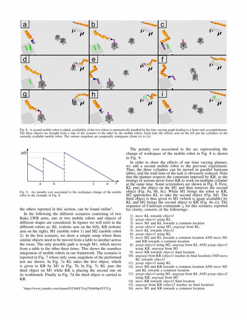
Fig. 8. A second mobile robot is added, availability of the two robots is automatically handled by the time varying graph leading to a faster task accomplishment.The three objects are brought from a side of the scenario to the other by the mobile robots. Each time the robotic arm on the left put the cylinders on thecurrently available mobile robot. The various snapshots are temporally contiguous (from (a) to (i)).
p(t)
ta b dc
Fig. 9. Arc penalty cost associated to the workspace change of the mobilerobot in the example of Fig. 8.
the others reported in this section, can be found online1.In the following the different scenarios consisting of two
Kuka LWR arms, one or two mobile robots and objects ofdifferent shapes are considered. In figures we will refer to thedifferent robots as: KL (robotic arm on the left), KR (roboticarm on the right), M1 (mobile robot 1) and M2 (mobile robot2). In the first scenario, we show a simple setup where threesimilar objects need to be moved from a table to another acrossthe room. The only possible path is trough M1, which movesfrom a table to the other three times. This shows the seamlessintegration of mobile robots in our framework. The scenario isreported in Fig. 7 where only some snapshots of the performedtest are shown. In Fig. 7a KL takes the first object, whichis given to KR by M1 in Fig. 7b. In Fig. 7c KL puts thethird object on M1 while KR is placing the second one onits workbench. Finally in Fig. 7d the third object is carried toKR.
1https://www.youtube.com/channel/UCb6ECYixj3Tobh9hpSYJ7Ug
The penalty cost associated to the arc representing thechange of workspace of the mobile robot in Fig. 8 is shownin Fig. 9.
In order to show the effects of our time varying planner,we add a second mobile robot to the previous experiment.Thus, the three cylinders can be moved in parallel betweentables, and the total time of the task is obviously reduced. Notethat the planner respects the constraint imposed by KR, as thetimings of actions never force KR to work on multiple cylinderat the same time. Some screenshots are shown in Fig. 8. First,KL puts the object on the M1 and then retrieves the secondobject (Fig. 8a, 8b, 8c). While M1 brings the robot to KR,M2 approaches KL to take the second object (Fig. 8d). Thethird object is thus given to M1 (which is again available) byKL and M2 brings the second object to KR (Fig. 8e–i)). Thesequence of Cartesian commands χ for this scenario, reportedfor clarity, consists of the followings:
1) move KL towards object12) grasp object1 using KL3) move M1 and KL towards a common location4) grasp object1 using M1, ungrasp from KL5) move KL towards object26) grasp object2 using KL7) move M2 and KL towards a common location AND move M1
and KR towards a common location8) grasp object2 using M2, ungrasp from KL AND grasp object1
using KR, ungrasp from M19) move KR towards object1 final location
10) ungrasp from KR (object1 reaches its final location) AND moveKL towards object3
11) grasp object3 using KL12) move M2 and KR towards a common location AND move M1
and KL towards a common location13) grasp object3 using M1, ungrasp from KL AND grasp object2
using KR, ungrasp from M214) move KR towards object2 final location15) ungrasp from KR (object2 reaches its final location)16) move M1 and KR towards a common location

17) grasp object3 using KR, ungrasp from M118) move KR towards object3 final location19) ungrasp from KR (object3 reaches its final location)
Finally, in Fig. 10, the same robot setup as in Fig. 8 isused, the goal is now to assembly different objects for whichreorientation is requested to achieve desired final arrangement.The re–orientation is automatically computed by the singleobject graph planner since the final configuration of the objectsis associated to a different node of the graph.
a
b
d
c
1
1
1
1
2
2
2
2
Fig. 10. Using different paths to move different objects: in this scenario, twopieces need to be mounted, and both are reoriented during their path frominitial to final configuration in order to obtain the desired assembly. The twoobject are brought in the correct order to be assembled, from (a) to (d).
VII. CONCLUSIONS
In this work we proposed a novel approach to handle objectsmoving in industrial scenarios with heterogeneous robots. Inparticular the approach is thought to be used in the domainof smart factories where complete automation is the keyfor competitive solutions. This work is an extension to ourprevious work [10] to handle multiple objects at the same timeand include mobile robots in the environment, and it is basedon a time varying graph on which a shortest path is performed
to find the optimal solution. All the code of this framework isavailable online2.
ACKNOWLEDGMENTS
This work is supported by the grant no. 645599 “SoMa”-Soft-bodied intelligence for Manipulation- within the H2020-ICT-2014-1 program.
REFERENCES
[1] Peter R Wurman, Raffaello D’Andrea, and Mick Mountz. Coordinatinghundreds of cooperative, autonomous vehicles in warehouses. AImagazine, 29(1):9, 2008.
[2] K Boyer, T Hult, and M Frohlich. Ocado: An alternative way to bridgethe last mile in grocery home delivery. Case No. 602-057, 1, 2002.
[3] Amazon picking challenge website, http://amazonpickingchallenge.org,2015.
[4] Hao Luo, Ji Fang, and George Q Huang. Real-time scheduling forhybrid flowshop in ubiquitous manufacturing environment. Computers& Industrial Engineering, 84:12–23, 2015.
[5] Tim Niemueller, Gerhard Lakemeyer, and Alexander Ferrein. Incremen-tal task-level reasoning in a competitive factory automation scenario. InAAAI Spring Symposium: Designing Intelligent Robots, 2013.
[6] Shiyong Wang, Jiafu Wan, Di Li, and Chunhua Zhang. Implementingsmart factory of industrie 4.0: an outlook. International Journal ofDistributed Sensor Networks, 2016, 2016.
[7] Basilio Bona, Luca Carlone, Marina Indri, and Stefano Rosa. Super-vision and monitoring of logistic spaces by a cooperative robot team:methodologies, problems, and solutions. Intelligent Service Robotics,7(4):185–202, 2014.
[8] Simon Bogh, Casper Schou, Thomas Ruhr, Yevgen Kogan, AndreasDomel, Manuel Brucker, Christof Eberst, Riccardo Tornese, ChristophSprunk, Gian Diego Tipaldi, et al. Integration and assessment of multiplemobile manipulators in a real-world industrial production facility. InISR/Robotik 2014; 41st International Symposium on Robotics; Proceed-ings of, pages 1–8. VDE, 2014.
[9] Alwin Hoffmann, Andreas Angerer, Andreas Schierl, Michael Vistein,and Wolfgang Reif. Service-oriented robotics manufacturing by reason-ing about the scene graph of a robotics cell. In ISR/Robotik 2014; 41stInternational Symposium on Robotics; Proceedings of, pages 1–8. VDE,2014.
[10] Hamal Marino, Mirko Ferrati, Alessandro Settimi, Carlos Rosales, andMarco Gabiccini. On the problem of moving objects with autonomousrobots: a unifying high-level planning approach. IEEE Robotics andAutomation Letters, 1:469–476, 2016.
[11] Kenneth L Cooke and Eric Halsey. The shortest route through a networkwith time-dependent internodal transit times. Journal of mathematicalanalysis and applications, 14(3):493–498, 1966.
[12] Stuart E Dreyfus. An appraisal of some shortest-path algorithms.Operations research, 17(3):395–412, 1969.
[13] Stefano Pallottino and Maria Grazia Scutella. Shortest path algorithms intransportation models: classical and innovative aspects. In Equilibriumand advanced transportation modelling, pages 245–281. Springer, 1998.
[14] Ariel Orda and Raphael Rom. Shortest-path and minimum-delayalgorithms in networks with time-dependent edge-length. Journal ofthe ACM, 37:607–625, 1990.
[15] Evangelos Kanoulas, Yang Du, Tian Xia, and Donghui Zhang. Findingfastest paths on a road network with speed patterns. In Data Engineering,2006. ICDE’06. Proceedings of the 22nd International Conference on,pages 10–10. IEEE, 2006.
[16] Giacomo Nannicini, Daniel Delling, Leo Liberti, and Dominik Schultes.Bidirectional A∗ search for time-dependent fast paths. In ExperimentalAlgorithms, pages 334–346. Springer, 2008.
[17] Mostafa K Ardakani and Madjid Tavana. A decremental approach withthe a algorithm for speeding-up the optimization process in dynamicshortest path problems. Measurement, 60:299–307, 2015.
[18] Sertac Karaman, Matthew R Walter, Alejandro Perez, Emilio Frazzoli,and Seth Teller. Anytime motion planning using the rrt*. In Roboticsand Automation (ICRA), 2011 IEEE International Conference on, page1478. IEEE, 2011.
[19] James J Kuffner and Steven M LaValle. Rrt-connect: An efficientapproach to single-query path planning. In Robotics and Automation.Proceedings. ICRA’00. IEEE International Conference on, volume 2,pages 995–1001. IEEE, 2000.
2http://dualmanipulation.bitbucket.org