Embed Size (px)
Citation preview

MIPI Automotive and A-PHYSM Update
Matt RonningMIPI Automotive Working Group Chair, Sony
Raj Kumar NagpalMIPI A-PHY Subgroup Chair, Synopsys
© 2019 MIPI Alliance, Inc.
Presentation Agenda
MIPI in AutomotiveMatt RonningMIPI Automotive Working Group Chair
An Overview of MIPI A-PHYRaj Kumar NagpalMIPI A-PHY Subgroup Chair

MIPI in Automotive
Matt RonningMIPI Automotive Working Group Chair
© 2019 MIPI Alliance, Inc.
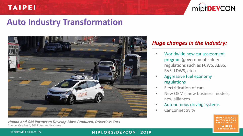
Auto Industry Transformation
Honda and GM Partner to Develop Mass Produced, Driverless CarsSource: October 4, 2018, Automotive News
Huge changes in the industry:
• Worldwide new car assessment program (government safety regulations such as FCWS, AEBS, RVS, LDWS, etc.)
• Aggressive fuel economy regulations
• Electrification of cars• New OEMs, new business models,
new alliances• Autonomous driving systems• Car connectivity

© 2019 MIPI Alliance, Inc.
NCAP Regulations Driving Sensors & Display Adoption
Source: Jabil, Inc
• Worldwide NCAP ADAS standards driving adoption of multiple high data rate “surround sensors”
• Displays for driver viewing of assistance imaging and information also required
Surround sensors for driver assistance
© 2019 MIPI Alliance, Inc.
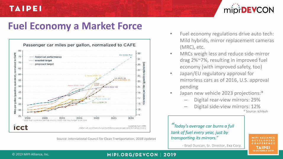
• Fuel economy regulations drive auto tech: Mild hybrids, mirror replacement cameras (MRC), etc.
• MRCs weigh less and reduce side-mirrordrag 2%~7%, resulting in improved fueleconomy (with improved safety, too)
• Japan/EU regulatory approval for mirrorless cars as of 2016, U.S. approval pending
• Japan new vehicle 2023 projections:*– Digital rear-view mirrors: 29%– Digital side-view mirrors: 12%
Fuel Economy a Market Force
* Source: Ichikoh
Source: International Council for Clean Transportation, 2018 Updates
“Today’s average car burns a full tank of fuel every year, just by transporting its mirrors.”
- Brad Duncan, Sr. Director, Exa Corp.

© 2019 MIPI Alliance, Inc. 7
Automotive Image SensorsSource: MIPI AsG BoF Meetings
Link with 10Gbps could support:• Up to RAW16, 10MP 1 max exposure channel @ 60fps; 10MP
2 max exposure channel @ 30fps; 2MP 4 max exposure channel @ 60fps
• Up to RAW24, 10MP, 1 max exposure channel @ 30 fps
Link with 5Gbps could support:• Up to RAW16, 2MP 2 max exposure channel @ 60fps• Up to RAW24, 2MP, 1 max exposure channel @ 60 fps

© 2019 MIPI Alliance, Inc.
Automotive Radar
Source: MIPI AsG BoF Meetings

© 2019 MIPI Alliance, Inc.
Autonomous Driving System
Data RatesFor image sensors, 10Gbps link could support:• RAW16 10MP 1 max exposure channel @ 60fps• RAW 16 2MP 4 max exposure channel @ 60fps
For radar, 12.5Gbps link could support:• Four “typical” 4-RX-channel (50MS/sec, 12b res)• Two “max” 4-RX-channel (80MS/sec, 16b res)
For display subsystems, 16Gbps link could support:• Ultra-HD 3840x2160 24-bits/pixel RGB 4:4:4 60 Hz
Highest data rate asymmetrical interfaces include those for camera, radar and display
GPS
Cameras
Radars
3D LIDAR
UltraSonic
Sensor Fusion
ProcessorECU
Action Engine
&VehicleControls
ECUs
Raw Data
Time Stamp
MapDatabase
V2V-V2ICommunications
PossibleSensor
Processing
CENTRAL CHALLENGE:
Display Subsystems
Transport raw image sensor and/or radar data to fusion processor, and processor/other generated data to the displays

© 2019 MIPI Alliance, Inc.
MIPI Alliance can provide auto OEMs with a standard I/F vs. current incompatible proprietary LVDS solutions, and enables the use/reuse of billions of instances of MIPI protocols like CSI-2
Why MIPI A-PHY for Automotive?
ProcessorSerDes
MIPI CSI-2
D-PHY2-4 Lanes
SerDesVia Coax
ImageSensor
MIPI CSI-2
D-PHY2-4 Lanes
CPUImageSensor
MIPI CSI-2
D-PHY2-4 Lanes
ProcessorEthernetController
MIPI CSI-2
D-PHY2-4 Lanes
E-Net
ViaTwisted
Pair
EthernetController
MIPI CSI-2
D-PHY2-4 Lanes
MIPI A-PHY
• High market growth driving MIPI member interest
• Ability to leverage economies of scale from mobile -> automotive
• Physical layer investigations using auto channels (<15m) as targets indicate technically feasible
MIPI asymmetric and low complexity automotive I/Fs complementary w/ automotive Ethernet solution:
Cautionary points:• Migration from consumer to automotive not trivial• MIPI Alliance not trying to replace existing auto network standards: CAN, LIN, MOST, Auto Ethernet, etc.• MIPI C-/D-PHYSM, MIPI CSI-2SM, MIPI DSI-2SM currently short range – board-level interface for automotive

© 2019 MIPI Alliance, Inc.
TechnologyProcess & Packaging
DesignDFM, DFT
ValidationQualification,
Characterization
ProductionTesting
SupportSupply Chain,
FA, FQE
AUTOMOTIVE REQUIREMENTSReliability Zero Defects Uninterrupted Supply Security Safety
STANDARDSISO 26262 AEC-Q100 TS16949 MISRA-C* Others
Over 50 Differences Between Automotive & Consumer Semiconductor Support Covered by Standards

© 2019 MIPI Alliance, Inc.
MIPI Automotive Timeline
v0.56 Feb. 26, 2018
v0.9 May 30, 2018
v0.8 March 28, 2018
v1.0.1 July 21, 2018
v1.1 August 14, 2019

© 2019 MIPI Alliance, Inc.
EMC Testing Overview
• Focused on the following immunity and related tests: – ALSE RF Ingress (ISO11452-2)– BCI (ISO11452-4)– Transient Immunity (ISO7637-3)– Screening Attenuation (IEC62153-4)
• Testing focused on coax rather than STP or SPP, and was performed by Sony, Murata and Shikoku Cable.
• Additional interference sources covered by individual company and included the following sources:– PCB near end crosstalk (NEXT)– Alien crosstalk– Car noise
• Use of EMC facilities: Murata Manufacturing Company, Yokohama tech center
• Cable assembly: Shikoku Cable, Rosenberger Japan, MD Elektronik
• Use of equipment: BMW, Valens
• Comment and discussion: MIPI Automotive WG member companies including BMW, Microchip, NXP, Valens
Cooperation with Other CompaniesPURPOSE:
To develop the noise and interference requirements in the automotive environment
TARGET EMC TEST:

© 2019 MIPI Alliance, Inc.
Automotive PHY Requirements Overview
• Bit Error Rate shall be less than 10-12 for both data and control streams
• Latency (Data Link Layer to Data Link Layer) shall be less than 16 µSec
• Design shall support DC power over the data lines with a maximum current limit of 0.5 A
• System shall operate with GND voltage offsets of up to ±1.0 V
• A-PHY shall provide the following modes: Shutdown, Start-Up, Active, Sleep andSafe State
• The A-PHY Data Link Layer shall be agnostic to the higher-level protocols andwith an overhead of 20% maximum
• Protocol Adaptation Layer shall supportMIPI protocols w/ minimal changes needed
• It shall be possible to aggregate multiple links for increased HS data BW
• A-PHY solution shall support BIST andsystem diagnostics (eg., link quality)
• A-PHY shall support system designs at the ASIL D level according to ISO26262:2018
• System clock shall be both embedded andasynchronous (i.e., decoupled from data rate clock)
• System cabling shall meet certain IL, RL and coupling requirements
• System operation shall be supported with specified automotive EMC requirements
Miscellaneous Other Requirements

An Overview of A-PHY
Raj Kumar NagpalMIPI A-PHY Subgroup Chair

© 2019 MIPI Alliance, Inc.
What is A-PHY?MIPI A-PHY is a physical layer specification targeted for advanced driver-assistance systems (ADAS) and autonomous driving systems (ADS) and other surround sensor applications in automotive (e.g., for displays, cameras), but also for other longer-reach applications such as IoT and industrial.
While most MIPI specifications are designed for shorter reaches for use within mobile devices, A-PHY will be capable of reaching up to 15 meters in the demanding automotive environment. A-PHY v1.0 will support speeds of 2-16 Gbps, with a roadmap to 24, 48 Gbps and beyond (e.g., 100 Gbps).

© 2019 MIPI Alliance, Inc.
MIPI A-PHY: Solving the Long-Reach ChallengeImplementation of camera and display specifications with necessary
bridging solutions vs. with A-PHY
Current implementation with proprietary bridging solutions
Implementation with A-PHY integrated into all components

© 2019 MIPI Alliance, Inc.
Co-Existence with Ethernet
Recognizing that IEEE 802.3ch Ethernet is an emerging network backbone, A-PHY will coexist in many implementations.
Illustration of concurrent use of asymmetric and symmetric data flows and interfaces

© 2019 MIPI Alliance, Inc.
A-PHY Data and Power Logical Structure
• Focus is on high throughput data to and from the system CPU over high-speed links with optimal wiring, cost and weight
• The high-speed data, control data and optional power share the same physical wiring

© 2019 MIPI Alliance, Inc.
A-PHY High-Level Structure A-PHY design includes a generic data link layer that will accommodate different protocol adaptation layers (both MIPI and non-MIPI)
• Camera module to ECU• Camera ECU to ECU • Lidar, radar• Display including touch and controls • A-PHY links over PCB interconnect
Example use cases:

© 2019 MIPI Alliance, Inc.
A-PHY Cable Type & Topology
100 Ω SDP cable up to 10 m, with up to 4 inline connectors with minimum segment of 30 cm
50 Ω Coax cable up to 15 m, with up to 4 inline connectors with minimum segment of 30 cm

© 2019 MIPI Alliance, Inc.
A-PHY VisionTo address the complete market, A-PHY will:• Provide options to suit various design needs• Support speeds of 2-16 Gbps, with a roadmap to 24,
48 Gbps and beyond (e.g., 100 Gbps)• Ensure scalability to stay ahead of growing
bandwidth requirements• Serve the broadest possible spectrum of OEMs,
suppliers and vendors
With this design, MIPI Alliance will offer a complete solution that addresses all speeds

© 2019 MIPI Alliance, Inc.
• Focused toward lower speed applications
• Intended for lowest cost, low-design-complexity solutions and to speed time to market
• Expected upper speed will be about 8 Gbps at 15 meters
• Based on NRZ-8b10b
A-PHY Profile Overview
• Can be used for all speeds • Interoperates with Profile 1• Provides superior EMC performance • Provides roadmap to higher speeds in
future A-PHY revisions• Based on PAM4/8/16 with PHY-level
retransmission scheme (RTS) and narrowband interference cancellation (NBIC)
The two profiles interoperate to ensurecompatibility, interoperability and system gradual scale-up
Profile 2Profile 1

© 2019 MIPI Alliance, Inc.
A-PHY Channel ThroughputForward channel throughput and gear definition
Gear Raw Data Rate
1 ≤ 2 Gbps
2 ≤ 4 Gbps
3 ≤ 8 Gbps
4 ≤ 12Gbps
5 ≤ 16 Gbps
Reverse channel, in full duplex with forward channel, will support the following data rates:• Low speed: 25 Mbps
(Aimed for camera and sensor products)
• High speed: 125 Mbps (Aimed for display and touchscreen products)

© 2019 MIPI Alliance, Inc.
A-PHY Key Technical Advantages• Asymmetric-optimized architecture
A-PHY is designed from scratch for high-speed asymmetric-only transmission from cameras/sensors to ECU, and ECU to display, while providing concurrent low-speed bidirectional traffic for command and control. The optimized asymmetric architecture allows for design simplification and lower cost than other/symmetric architectures.
• Mobile protocol reuseAfter successful deployment in billions of smartphones and IOT devices, the MIPI protocols are well-proven for direct leverage into automotive.
• Hardware-only protocol layersAs in mobile applications using C-PHY/D-PHY layering, A-PHY is tightly coupled with the CSI-2/DSI-2 protocol layers, thus essentially operating with hardware-only protocol layers without software intervention. This architecture is contrasted to other interfaces that are designed with more flexibility and utilize software layers to accomplish this flexibility.

© 2019 MIPI Alliance, Inc.
A-PHY Key Technical Advantages• Optimized architecture for wiring, cost and weight
By its optimized asymmetric architecture and hardware protocol layering, A-PHY implementations achieve optimized cabling wiring, cost and weight requirements. This is increasingly important as the number of electronic components and their interface cabling increases on the road to autonomy.
• Flexible link layer support of other protocolsMIPI Alliance expects to work with other organizations leveraging their native protocols into automotive. This includes VESA, which is adapting its DisplayPort protocol specification for automotive use. To accommodate these developing specifications, A-PHY includes a generic Data Link Layer that accommodates different protocol adaptation layers, with a plan to support VESA’s vehicular DisplayPort protocol.
• High EMC immunityMIPI has invested significantly to analyze and measure the harsh automotive channel, and has concluded that an architecture based on a Narrowband Interference Canceller (NBIC) and Retransmission system (RTS) provides the most robust performance, particularly for the applications requiring the higher data rates at longer distances.
© 2019 MIPI Alliance, Inc. 27
ADDITIONAL RESOURCES
More information can be found at:• MIPI Alliance Advances Activities for ADAS, ADS and Other Automotive
Applications (Press release, October 2019)
• Automotive Applications Drive MIPI A-PHY Development (Blog, May 2019)
• MIPI Alliance Meets the Needs of Autonomous Driving (DevCon presentation, October 2018)
• MIPI Alliance Extends Interface Standards to Support the Automotive Market(Webinar, April 2018)
• MIPI Alliance to Advance Autonomous Driving, other Automotive Applications with New Data Interface Specifications at 12-24 Gbps and Beyond(Press release, August 2018)
• MIPI Alliance Expands Reach with New Automotive Working Group(Press release, March 2018)
• Automotive Working Group page
• A-PHY specification page
Download the new MIPI in Automotive white paper
Other Resources


![[Samsung NX100] New way to shoot with i-Function as a mirrorless camera](https://img.pdfslide.us/doc/110x75/54b356254a7959c44c8b4572/samsung-nx100-new-way-to-shoot-with-i-function-as-a-mirrorless-camera.jpg)