Embed Size (px)
Citation preview

GSM Association Non-confidential
Official Document CLP.23 - MIoT Test Cases
V1.0 Page 1 of 40
MIoT Test Cases
Version 1.0
19 December 2016
This is a Non-binding Permanent Reference Document of the GSMA
Security Classification: Non-confidential
Access to and distribution of this document is restricted to the persons permitted by the security classification. This document is confidential to the
Association and is subject to copyright protection. This document is to be used only for the purposes for which it has been supplied and
information contained in it must not be disclosed or in any other way made available, in whole or in part, to persons other than those permitted
under the security classification without the prior written approval of the Association.
Copyright Notice
Copyright © 2017 GSM Association
Disclaimer
The GSM Association (“Association”) makes no representation, warranty or undertaking (express or implied) with respect to and does not accept
any responsibility for, and hereby disclaims liability for the accuracy or completeness or timeliness of the information contained in this document.
The information contained in this document may be subject to change without prior notice.
Antitrust Notice
The information contain herein is in full compliance with the GSM Association’s antitrust compliance policy.

GSM Association Non-confidential
Official Document CLP.23 - MIoT Test Cases
V1.0 Page 2 of 40
Introduction 5
Overview 5
Scope 5
Definitions 5
Abbreviations 8
References 9
Basic Operation 11
Cell Selection 11
CAT-M1 Device Cell Selection Procedure - CLP.23_2.1.1_TC_001 11
CAT-NB1 Device Cell Selection Procedure - CLP.23_2.1.2_TC_001 11
Registration (Attach/Detach) 12
CAT-M1 Device Attach Procedure with Control Plane CIoT EPS
Optimazation - CLP.23_2.2.1_TC_001 12
CAT-M1 Device Attach Procedure with User Plane CIoT EPS
Optimization - CLP.23_2.2.2_TC_001 12
CAT-M1 Device Attach Procedure with CIoT EPS Optimizations (EMM
Registered without PDN Connection) - CLP.23_2.2.3_TC_001 13
CAT-M1 Device Detach Procedure - CLP.23_2.2.4_TC_001 14
CAT-NB1 device Attach Procedure with Control Plane CIoT EPS
Optimizations CLP.23_2.2.5_TC_001 14
CAT-NB1 Device Attach Procedure with User Plane CIoT EPS
Optimization CLP.23_2.2.6_TC_001 15
CAT-NB1 Device Attach Procedure with CIoT EPS Optimizations (EMM
Registered without PDN Connection) CLP.23_2.2.7_TC_001 16
CAT-NB1 Device Attach Procedure with CIoT EPS Optimizations (SMS
transfer without Combined Attach) CLP.23_2.2.8_TC_001 17
CAT-NB1 Device Detach Procedure CLP.23_2.2.9_TC_001 17
Device Capabilities 18
CAT-M1 Device Capability Transfer / Success - RRC Level -
CLP.23_2.3.1_TC_001 18
CAT-M1 Device Capability Transfer / Success - NAS Level -
CLP.23_2.3.2_TC_001 18
CAT-NB1 device Capability Transfer / Success - RRC Level
CLP.23_2.3.3_TC_001 18
CAT-NB1 device Capability Transfer / Success - NAS Level
CLP.23_2.3.4_TC_001 19
Data Transfer and Throughput 19
CAT M1 Data Transfer and Throughput with Control Plane CIoT EPS
Optimizations - CLP.23_2.4.1_TC_001 19
CAT-M1 Data Transfer and Throughput with User Plane CIoT EPS
Optimizations - CLP.23_2.4.2_TC_001 20
CAT-NB1 Device Data Transfer and Throughput with Control Plane CIoT
EPS Optimizations CLP.23_2.4.3_TC_001 20
CAT-NB1 Device Data Transfer and Throughput with User Plane CIoT
EPS Optimizations CLP.23_2.4.4_TC_001 21

GSM Association Non-confidential
Official Document CLP.23 - MIoT Test Cases
V1.0 Page 3 of 40
Mobility 21
CAT-M1 Device Cell Reselection Procedure - CLP.23_2.5.1_TC_001 21
CAT-M1 Device Handover Procedure with CIoT EPS Optimization -
CLP.23_2.5.2_TC_001 22
CAT-NB1 device Intra-Frequency Cell Reselection
CLP.23_2.5.3_TC_001 22
CAT-NB1 device Inter-Frequencies Cell Reselection
CLP.23_2.5.4_TC_001 23
CAT-NB1 device Cell Redirection CLP.23_2.5.5_TC_001 23
Suspend/Resume 24
CAT-M1 Device Suspend Procedure with User Plane CIoT EPS
Optimizations - CLP.23_2.6.1_TC_001 24
CAT-M1 Device Resume Procedure with User Plane CIoT EPS
Optimizations - TS23_2.6.2_TC_001 24
CAT-NB1 device Suspend Procedure with User Plane CIoT EPS
Optimizations CLP.23_2.6.3_TC_001 25
CAT-NB1 device Resume Procedure with User Plane CIoT EPS
Optimizations CLP.23_2.6.4_TC_001 25
Enhanced Coverage 26
Random Access 26
NPRACH configuration in Random Access - CLP.23_3.1.1_TC_001 26
PRACH configuration in Random Access - CLP.23_3.1.2_TC_001 26
Data Transfer and Throughput 27
Data Transfer and Throughput of CAT-NB1 UE with Control Plane CIoT
EPS Optimizations - CLP.23_3.2.1_TC_001 27
Data Transfer and Throughput of CAT-NB1 UE with User Plane CIoT
EPS Optimizations - CLP.23_3.2.2_TC_001 27
Data Transfer and Throughput of CAT-M1 UE - CLP.23_3.2.3_TC_001 28
Power Test Cases 28
PSM Operation 29
PSM Request and Activation - CLP.23_4.1.1_TC_001 29
MT Data in PSM State - CLP.23_4.1.2_TC_001 30
MO Data in PSM State - CLP.23_4.1.3_TC_001 30
Periodic Tracking/Routing Area Update - CLP.23_4.1.4_TC_001 31
Reduced Current Drain in PSM- CLP.23_4.1.5_TC_001 31
Periodic Tracking Area Update, T3412 - CLP.23_4.1.6_TC_001 32
I-eDRX Operation 33
eDRX Request and Activation - CLP.23_4.2.1_TC_001 33
Service Layer (oneM2M) 34
USIM/eUICC OTA 34
USIM Toolkit 34
Antenna Performance 34
Device Management (LwM2M) 34
Mapping of Test Cases to Requirements 35
Annex A Document Management 40

GSM Association Non-confidential
Official Document CLP.23 - MIoT Test Cases
V1.0 Page 4 of 40
A.1 Document History 40
A.2 Other Information 40

GSM Association Non-confidential
Official Document CLP.23 - MIoT Test Cases
V1.0 Page 5 of 40
1 Introduction
1.1 Overview
This document provides the test cases that may be carried out for LPWA (Low Power Wide
Area) Mobile IoT modules and devices that are to be deployed on early adopter networks
prior to PTCRB and GCF certification being available in mid-2017.
1.2 Scope
This document defines all test cases for Accreditation of LPWA MIoT modules and devices
that are to be deployed in mobile networks that support LPWA modules and devices, prior to
the PTCRB and GCF certification process being in place. This scope excludes any type or
form of Certification as this is outside the remit of the document.
These test cases shall be executed against the requirements document as identified within
the MIoT Requirements document CLP22 v1.0 which reflects the specifications as identified
in the 3GPP R13 Specifications published in June 2016.
This document does not replicate any test cases that are currently defined within the GSMA
Device Connection Efficiency Test Book TS.35 [9]. Any test cases in this respect will be
agreed between the respective MNO’s and their Vendors and is outside the scope of this
document.
It should be noted that the test cases listed within this document are those that are deemed
as a priority by the MNOs (Mobile Network Operators) for accreditation of MIoT devices onto
their networks. However, the final subset of test cases to be executed will be the subject of
discussion and agreement with the MNO and its Manufacturers in respect of the various
features and functionality, that may be available on the respective network infrastructure and
MIoT devices being deployed at the time of testing.
1.3 Definitions
The key words "SHALL", "SHOULD" and "MAY", within this document are to be interpreted as described in RFC 2119 [19], an abstract of which is included within the table below.
Term Description
MUST This word, or the terms "REQUIRED" or "SHALL", mean that the definition is an absolute requirement of the specification.
SHOULD This word, or the adjective "RECOMMENDED", mean that there may exist valid reasons in particular circumstances to ignore a particular item, but the full implications must be understood and carefully weighed before choosing a different course.
MAY This word, or the adjective "OPTIONAL", mean that an item is
truly optional. One vendor may choose to include the item
because a particular marketplace requires it or because the
vendor feels that it enhances the product while another vendor
may omit the same item. An implementation which does not
include a particular option MUST be prepared to interoperate with
another implementation which does include the option, though
perhaps with reduced functionality. In the same vein an
implementation which does include a particular option MUST be

GSM Association Non-confidential
Official Document CLP.23 - MIoT Test Cases
V1.0 Page 6 of 40
Term Description
prepared to be interoperate with another implementation which
does not include the option (except, of course, for the feature the
option provides.)
Term Description
Actor
Physical entity (person, company or organisation) that can assume a
Role in the functional architecture. It is possible for an Actor to
assume multiple Roles in the same functional architecture.
Connectivity Parameters
A set of data (for example SMSC address) required by the eUICC to
open a communication channel (for example SMS, HTTPS) on a
dedicated network.
Customer A paying party, in particular a legally responsible juridical person or
entity.
Device
Equipment into which an Embedded UICC and a communication
module are inserted during assembly. Examples include Utility
meter, car and camera.
Disabled (Profile)
The state of a Profile where all files and applications (for example
NAA) present in the Profile are not selectable over the eUICC-
Terminal interface.
Embedded UICC (eUICC)
A UICC which is not easily accessible or replaceable, is not intended
to be removed or replaced in the Device, and enables the secure
changing of Profiles.
Enabled (Profile) The state of a Profile when its files and/or applications (for example,
NAA) are selectable over the UICC-Terminal interface.
eUICC Manufacturer Supplier of the eUICCs and resident software (for example firmware
and operating system).
International Mobile
Subscriber Identity
Unique identifier owned and issued by Mobile operators to (U) SIM
applications to enable Devices to attach to a network and use
services.
MIoT Device
A Mobile IoT (MIoT) Device is a generic term to indicate one of the
following 3GPP standard technologies for LPWA: CAT-M1, CAT-
NB1 and EC-GSM-IoT.
Mobile Network Operator An entity providing access capability and communication services to
its Customers through a mobile network infrastructure.
3GPP module
A communications module complying to one or more of the 3GPP
communication technologies such as 2G, 3G, EC-GSM-IoT, CAT-
NB1 or CAT-M1, this includes all necessary eUICC or UICC
components. Can also be called User Equipment or UE.

GSM Association Non-confidential
Official Document CLP.23 - MIoT Test Cases
V1.0 Page 7 of 40
Network Access Application An application residing on a UICC which provides authorisation to
access a network for example a USIM application.
Profile
Combination of a file structure, data and applications to be
provisioned onto, or present on, an eUICC and which allows, when
enabled, the access to a specific mobile network infrastructure.
Profile Component
A Profile Component is an element of the Profile and may be one of
the following:
An element of the file system like an MF, EF or DF
An Application, including NAA and Security Domain
POL1
MNO-SD.
Roles Roles are representing a logical grouping of functions.
SIM
Subscriber Identity Module; a physical entity that contains keys and
ID required to authenticate a user on a mobile network.“SIM” is
commonly used to refer to the physical entity that is technically
called the UICC (see UICC definition below).This document
generally uses “SIM” to refer to the physical entity
Subscriber
An entity (associated with one or more users) that is engaged in a
Subscription with a Telecommunication Service Provider. The
Subscriber is allowed to subscribe and unsubscribe to services, to
register a user or a list of users authorised to use those services,
and also to set the limits relative to the use that associated users
make of those services.
Subscription Describes the commercial relationship between the Subscriber and
the Telecommunication Service Provider.
Subscription Manager Data
Preparation
Role that prepares the Profiles and manages the secure download
and installation of these Profiles onto the eUICC.
Subscription Manager
Secure Routing
Role that securely performs functions of Platform Management
commands and the transport of Profile Management commands.
UICC Universal Integrated Circuit Card; the physical entity that contains as
a minimum the SIM/USIM application
USIM An application that runs on the UICC and provides authentication
functions similar to those provided by the SIM in pre-3G systems
Telecommunication Service
Provider
The organization through which the Subscriber obtains PLMN
telecommunication services. This is usually the network operator or
possibly a separate body.
GSM Association Non-confidential
Official Document CLP.23 - MIoT Test Cases
V1.0 Page 8 of 40
1.4 Abbreviations
Term Description
3GPP 3rd Generation Partnership Project
BGA Ball Grid Array
CAT-NB1 Category Narrow Band 1
CAT-M1 Category M1
C-DRX Connected mode DRX
CIoT Cellular Internet of Things
dB Decibel
dBm Decibel-referenced to 1 milliwatt
DFN Dual Flat No lead package
DRX Discontinuous Reception
DL Downlink
E-DRX Extended DRX
ETSI European Telecommunications Standards Institute
EC-GSM-IoT Extended Coverage GSM Internet of Things
EDGE Enhanced Data Rates for GSM Evolution
eDRX Extended Discontinuous Receive
EGPRS Enhanced General packet radio service
eUICC Embedded Universal Integrated Circuit Card
FDD Frequency Division Duplexing
GERAN GSM EDGE Radio Access Network
GPRS General Packet Radio Service
GMSK Gaussian minimum shift keying
GSM Global System for Mobile Communications
GSMA GSM Association
I-DRX Idle mode DRX
IoT Internet of Things
IMEI International Mobile Station Equipment Identity
IP Internet Protocol
IPSec Internet Protocol Security
LoRa Long Range
LPUC Low Power Use Case
LPWA Low Power Wide Area
LTE Long-Term Evolution
LTE eMTC Long-Term Evolution Enhanced Machine Type Communications
LTE MTC Long-Term Evolution Machine Type Communications
M2M Machine-to-machine

GSM Association Non-confidential
Official Document CLP.23 - MIoT Test Cases
V1.0 Page 9 of 40
Term Description
MCL Maximum Coupling Loss
MFF2 M2M Form Factor 2
MHz Mega Hertz
MNO Mobile Network Operator
MS Mobile Station
MTC Machine Type Communications
NB-IoT Narrow Band Internet of Things
OFDMA Orthogonal Frequency-Division Multiple Access
OTA Over The Air
PLMN Public Land Mobile Network
PSM Power Save Mode
QoS Quality of Service
RAN Radio Access Network
RF Radio Frequency
SC-FDMA Single-carrier frequency-division multiple access
SIM Subscriber Identity Module (an application running on a UICC)
SMS Short Message Service
TCO Total Cost of Ownership
TDMA Time division multiple access
TR Technical Report
UE User Equipment
UICC Universal Integrated Circuit Card (sometimes known as the SIM card)
UL Uplink
USIM Universal Subscriber Identity Module
UTDOA Uplink-Time Difference of Arrival
WAN Wide Area Network
Wi-Fi Wireless Fidelity
WLCSP Wafer-level redistribution Chip Scale Package
1.5 References
Ref Doc Number Title
[1] 3GPP TS 31.120 UICC-Terminal Interface; Physical, electrical and logical
test specification, Release 13 or higher.
[2] 3GPP TS 31.121
“UICC-Terminal interface; Universal Subscriber Identity
Module (USIM) application test specification, Release 13
or higher.
[3] 3GPP TS 31.124 Mobile Equipment (ME) conformance test specification;
Universal Subscriber Identity Module Application Toolkit

GSM Association Non-confidential
Official Document CLP.23 - MIoT Test Cases
V1.0 Page 10 of 40
Ref Doc Number Title
(USAT) conformance test specification, Release 13 or
higher.
[4]
OMA-ETS-
LightweightM2M-
V1_0
Enabler Test Specification for Lightweight M2M v1.0,
publication date 20160726 or later.
[5] oneM2M TS
0013 oneM2M Interoperability Testing
[6] oneM2M TS
0017 oneM2M Implementation Conformance Statements
[7] oneM2M TS
0018 oneM2M Test Suite Structure and Test Purposes
[8] oneM2M TS
0019
oneM2M Abstract Test Suite & Implementation eXtra
Information for Test
[9] GSMA TS.35 IoT Device Connection Efficiency Test Book, Version 3.0,
30 March 2016
[10] 3GPP TS.34.114 User Equipment (UE) / Mobile Station (MS) Over The Air (OTA)
antenna performance; Conformance testing
[11] 3GPP TS.37.544
Universal Terrestrial Radio Access (UTRA) and Evolved
UTRA (E-UTRA); User Equipment (UE) Over The Air
(OTA) performance; Conformance testing
[12] CTIA OTA Test
Plan v3.6 Test Plan for Wireless Device Over-the-Air Performance
[13] RFC2119 Key words for use in RFCs to Indicate Requirement Levels
[14] 3GPP TS.36.304 Evolved Universal Terrestrial Radio Access (E-UTRA);
User Equipment (UE) procedures in idle mode
[15] 3GPP TS36.321 Evolved Universal Terrestrial Radio Access (E-UTRA);
Medium Access Control (MAC) protocol specification
[16] 3GPP TS.36.331 Evolved Universal Terrestrial Radio Access (E-UTRA);
Radio Resource Control (RRC); Protocol specification

GSM Association Non-confidential
Official Document CLP.23 - MIoT Test Cases
V1.0 Page 11 of 40
2 Basic Operation
2.1 Cell Selection
CAT-M1 Device Cell Selection Procedure - CLP.23_2.1.1_TC_001
Purpose To verify that CAT-M1 device could successfully perform the cell selection procedure with CIoT EPS Optimizations
Requirement under test
CLP.22_2.1.2_REQ_001
Entry Criteria CAT-M1 Device is configured with “CIoT EPS Optimizations” in “Preferred and Supported Network Behaviour”
CAT-M1 Device is Switched OFF
The network is configured to support “CIoT EPS Optimizations”
Test Procedure CAT-M1 Device is Switched ON
CAT-M1 Device is in EMM-IDLE mode reads SIB1
EUTRAN Cell fulfils all requirements for a suitable cell including the cell selection criteria for a cell based on Qrxlevmin which are also fulfilled (Srxlev > 0) as defined in the clause 5.2.3.2 of 3GPP TS 36.304 [14]
Or
EUTRAN Cell fulfils all requirements for a suitable cell including the cell selection criteria for a cell based on Qqualmin which are also fulfilled (Srxlev > 0 AND Squal > 0) as defined in the clause 5.2.3.2 of 3GPP TS 36.304 [14]
CAT-M1 Device will select the EUTRAN cell and starts to read SIB2 Message to
verify that “CIoT EPS Optimizations” is supported in EUTRAN Cell.
Exit Criteria (Pass Criteria)
Verify that CAT-M1 Device performed cell selection with suitable cell including the validation of the cell selection criteria (S>0)
CAT-NB1 Device Cell Selection Procedure - CLP.23_2.1.2_TC_001
Purpose To verify that the CAT-NB1 device could properly execute the Cell selection according the 3GPP 36.304.[14]
Requirement under test
TS.22_2.1.2_REQ_001
Entry Criteria CAT-NB1 UE is powered off.
Control Plane CIoT EPS optimizations shall be supported by device and Network.
The NB-IoT cells with good RSRP/RSRQ condition are available.
Test Procedure Power on the CAT-NB1 UE.
CAT-NB1 Device is in EMM-IDLE mode and reads SIB1-NB message
CAT-NB1 UE evaluates the NB-IoT Cells based on Qrxlevmin and selects one suitable NB-IoT cell which Srxlev > 0 is fulfilled
or
CAT-NB1 UE evaluates the NB-IOT Cells based on Qqualmin and selects one suitable NB-IOT cell which Srxlev > 0 AND Squal >0 are fulfilled.
CAT-NB1 device starts to register on the NB-IoT cell.
Exit Criteria CAT-NB1 UE successfully camps on the NB-IoT cell according to the criterion defined in section 5.2.3.2a of 3GPP 36.304

GSM Association Non-confidential
Official Document CLP.23 - MIoT Test Cases
V1.0 Page 12 of 40
2.2 Registration (Attach/Detach)
CAT-M1 Device Attach Procedure with Control Plane CIoT EPS
Optimazation - CLP.23_2.2.1_TC_001
Purpose To verify that CAT-M1 device could successfully perform LTE Attach Procedure with Control Plane CIoT EPS Optimizations
Requirement under test
CLP.22_2.2.2_REQ_001
Entry Criteria CAT-M1 Device is configured with “Control Plane CIoT EPS Optimizations” in “Preferred and Supported Network Behaviour”
CAT-M1 Device is Switched OFF
The network is configured to support “Control Plane CIoT EPS Optimizations”
Test Procedure CAT-M1 Device is Switched ON
CAT-M1 Device is in EMM-IDLE mode reads SIB-2 to verify that “Control Plane CIoT EPS Optimizations” is broadcast in EUTRAN Cell.
CAT-M1 Device transmits an RRC Connection Request Message and eNodeB transmits an RRC Connection Setup Message.
CAT-M1 Device transmits an RRC Connection Setup Complete Message to confirm the successful completion of the connection establishment by specify that UE supports “Control Plane CIoT EPS Optimizations”
CAT-M1 Device initiates the Attach Procedure by sending Attach Request Message by specifies that UE supports “Control Plane CIoT EPS Optimizations” in “UE Network Capability IE” together with a PDN CONNECTIVITY REQUEST Message in the ESM Message Container Information Element to request PDN Connectivity
The network responds to the CAT-M1 Device with Attach Accept Message that supports “Control Plane CIoT EPS Optimization” in “EPS Network Feature Support” with the Activate Default EPS Bearer Context Request Message shall include PDN related parameters.
CAT-M1 Device completes the Attach Procedure by sending the Attach Complete Message together with an Activate Default EPS Bearer Context Accept Message in the ESM Message Container Information Element to the network
Exit Criteria (Pass Criteria)
Verify that CAT-M1 Device received with “Control Plane CIoT EPS Optimization” in Attach Accept Message and successfully attach procedure by sending Attach Complete Message
CAT-M1 Device Attach Procedure with User Plane CIoT EPS
Optimization - CLP.23_2.2.2_TC_001
Purpose To verify that CAT-M1 device could successfully perform LTE Attach Procedure with User Plane CIoT EPS Optimizations
Requirement under test
CLP.22_2.2.2_REQ_001

GSM Association Non-confidential
Official Document CLP.23 - MIoT Test Cases
V1.0 Page 13 of 40
Entry Criteria CAT-M1 Device is configured with “User Plane CIoT EPS Optimizations” in “Preferred and Supported Network Behaviour”
If the CAT-M1 Device indicates support of User Plane CIoT EPS optimization then it shall also indicate support of S1-U data transfer
CAT-M1 Device is Switched OFF
The network is configured to support “User Plane CIoT EPS Optimizations” and “S1-U Data transfer”
Test Procedure CAT-M1 Device is Switched ON
CAT-M1 Device is in EMM-IDLE mode reads SIB-2 to verify that “User Plane CIoT EPS Optimizations” is broadcast in EUTRAN Cell.
CAT-M1 Device transmits an RRC Connection Request Message and eNodeB transmits an RRC Connection Setup Message.
CAT-M1 Device transmits an RRC Connection Setup Complete Message to confirm the successful completion of the connection establishment by specify that UE supports “User Plane CIoT EPS Optimizations”
CAT-M1 Device initiates the Attach Procedure by sending Attach Request Message by specifies that UE supports “User Plane CIoT EPS Optimizations” & “S1-U Data Transfer” in “UE Network Capability IE” together with a PDN CONNECTIVITY REQUEST Message in the ESM Message Container Information Element to request PDN Connectivity
The network responds to the CAT-M1 Device with Attach Accept Message that supports “User Plane CIoT EPS Optimization” in “EPS Network Feature Support” with the Activate Default EPS Bearer Context Request Message shall include PDN related parameters.
CAT-M1 Device completes the Attach Procedure by sending the Attach Complete Message together with an Activate Default EPS Bearer Context Accept Message in the ESM Message Container Information Element to the network
Exit Criteria (Pass Criteria)
Verify that CAT-M1 Device received with “User Plane CIoT EPS Optimization” in Attach Accept Message and successfully attach procedure by sending Attach Complete Message
CAT-M1 Device Attach Procedure with CIoT EPS Optimizations (EMM
Registered without PDN Connection) - CLP.23_2.2.3_TC_001
Purpose To verify that CAT-M1 device could successfully perform LTE Attach Procedure without PDN Connection
Requirement under test
CLP.22_2.2.2_REQ_001
Entry Criteria CAT-M1 Device is configured with “attachwithoutPDN Connectivity” in “Preferred and Supported Network Behaviour”
CAT-M1 Device is Switched OFF
The network is configured to support “attachwithoutPDN Connectivity”

GSM Association Non-confidential
Official Document CLP.23 - MIoT Test Cases
V1.0 Page 14 of 40
Test Procedure CAT-M1 Device is Switched ON
CAT-M1 Device is in EMM-IDLE mode reads SIB-2 to verify that “attachwithoutPDN Connectivity” is broadcast in EUTRAN Cell.
CAT-M1 Device transmits an RRC Connection Request Message and eNodeB transmits an RRC Connection Setup Message.
CAT-M1 Device transmits an RRC Connection Setup Complete Message to confirm the successful completion of the connection establishment by specify that UE supports “attachwithoutPDN Connectivity”
CAT-M1 Device initiate the Attach procedure by including the ATTACH REQUEST Message by specify that UE supports “attachwithoutPDN Connectivity” in “UE Network Capability IE” with ESM DUMMY Message
The Network responds to the CAT-M1 Device with Attach Accept Message that supports “attachwithoutPDN Connectivity” in “EPS Network Feature Support” with ESM DUMMY Message.
CAT-M1 Device completes the Attach Procedure by sending the Attach Complete Message with ESM DUMMY Message
Exit Criteria (Pass Criteria)
Verify that CAT-M1 Device received with “attachwithoutPDN Connectivity” in Attach Accept Message and successfully attach procedure by sending Attach Complete Message
CAT-M1 Device Detach Procedure - CLP.23_2.2.4_TC_001
Purpose To verify that CAT-M1 device could successfully perform LTE Detach Procedure with CIoT EPS Optimizations
Requirement under test
CLP.22_2.2.2_ REQ_002
Entry Criteria CAT-M1 Device is configured with “CIoT EPS Optimizations” in “Preferred and Supported Network Behaviour”
CAT-M1 Device is Switched ON
CAT-M1 Device in RRC_CONNECTED State
The network is configured to support “CIoT EPS Optimizations”
Test Procedure CAT-M1 Device will initiate an Explicit Detach procedure to the Network
CAT-M1 Device sends Detach Request Message (GUTI, Switch Off) in NAS Level to the Network
If Switch Off indicated that detach is not due to a switch off situation, the network sends a Detach Accept Message to the CAT-M1 Device
Exit Criteria (Pass Criteria)
Verify that CAT-M1 Device sends Detach Request Message to the Network.
CAT-NB1 device Attach Procedure with Control Plane CIoT EPS
Optimizations CLP.23_2.2.5_TC_001
Purpose To verify that the CAT-NB1 device could successfully complete LTE Attach Procedure with Control Plane CIoT EPS Optimizations.
Requirement under test
CLP.22_2.2.2_REQ_001

GSM Association Non-confidential
Official Document CLP.23 - MIoT Test Cases
V1.0 Page 15 of 40
Entry Criteria CAT-NB1 Device shall be configured with “Control Plane CIoT EPS Optimizations” in “Preferred and Supported Network Behaviour”.
The network shall be configured to support “Control Plane CIoT EPS Optimizations”.
CAT-NB1 Device is Switched OFF.
Test Procedure CAT-NB1 Device is Switched ON
CAT-NB1 Device transmits an RRCConnectionRequest-NB Message and eNodeB transmits an RRCConnectionSetup-NB Message.
CAT-NB1 Device transmits an RRCConnectionSetupComplete-NB Message to confirm the successful completion of the connection.
CAT-NB1 Device initiates the Attach Procedure by sending Attach Request Message by specifies that UE supports “Control Plane CIoT EPS Optimizations” in “UE Network Capability IE” together with a PDN CONNECTIVITY REQUEST Message in the ESM Message Container Information Element to request PDN Connectivity
The network responds to the CAT-NB1 Device with Attach Accept Message that supports “Control Plane CIoT EPS Optimization” in “EPS Network Feature Support” with the Activate Default EPS Bearer Context Request Message shall include PDN related parameters.
CAT-NB1 Device completes the Attach Procedure by sending the Attach Complete Message together with an Activate Default EPS Bearer Context Accept Message in the ESM Message Container Information Element to the network
Exit Criteria Verify that CAT-NB1 Device received with “Control Plane CIoT EPS Optimization” in Attach Accept Message and successfully complete attach procedure by sending Attach Complete Message
CAT-NB1 Device Attach Procedure with User Plane CIoT EPS
Optimization CLP.23_2.2.6_TC_001
Purpose To verify that CAT-NB1 device could successfully perform LTE Attach Procedure with User Plane CIoT EPS Optimizations.
Requirement under test
CLP.22_2.2.2_REQ_001
Entry Criteria CAT-NB1 Device shall be configured with “Control Plane CIoT EPS Optimizations” and “User Plane CIoT EPS Optimizations” in “Preferred and Supported Network Behaviour”.
If the CAT-NB1 Device indicates support of User Plane CIoT EPS optimizations then it shall also indicate support of S1-U data transfer.
The network shall be configured to support “Control Plane CIoT EPS Optimizations” and “User Plane CIoT EPS Optimizations” and “S1-U Data transfer”.
CAT-NB1 Device is Switched OFF.

GSM Association Non-confidential
Official Document CLP.23 - MIoT Test Cases
V1.0 Page 16 of 40
Test Procedure CAT-NB1 Device is Switched ON
CAT-NB1 Device transmits an RRCConnectionRequest-NB Message and eNodeB transmits an RRCConnectionSetup-NB Message.
CAT-NB1 Device transmits an RRCConnectionSetupComplete-NB Message to confirm the successful completion of the connection establishment by specify that UE supports “User Plane CIoT EPS Optimizations” .
CAT-NB1 Device initiates the Attach Procedure by sending Attach Request Message by specifies that UE supports “Control Plane CIoT EPS Optimizations” and “User Plane CIoT EPS Optimizations” and “S1-U Data Transfer” in “UE Network Capability IE” together with a PDN CONNECTIVITY REQUEST Message in the ESM Message Container Information Element to request PDN Connectivity.
The network responds to the CAT-NB1 Device with Attach Accept Message that supports “Control Plane CIoT EPS Optimizations” and “User Plane CIoT EPS Optimization” in “EPS Network Feature Support” with the Activate Default EPS Bearer Context Request Message shall include PDN related parameters.
CAT-NB1 Device completes the Attach Procedure by sending the Attach Complete Message together with an Activate Default EPS Bearer Context Accept Message in the ESM Message Container Information Element to the network
Exit Criteria Verify that CAT-NB1 Device received with “User Plane CIoT EPS Optimization” in Attach Accept Message and successfully attach procedure by sending Attach Complete Message
CAT-NB1 Device Attach Procedure with CIoT EPS Optimizations (EMM
Registered without PDN Connection) CLP.23_2.2.7_TC_001
Purpose To verify that CAT-NB1 device could successfully perform LTE Attach Procedure with EMM Registered without PDN Connection
Requirement under test
CLP.22_2.2.2_REQ_001
Entry Criteria CAT-NB1 Device shall be configured with “Control Plane CIoT EPS Optimizations” and “Attach without PDN Connectivity” in “Preferred and Supported Network Behaviour”
The network shall be configured to support “Control Plane CIoT EPS Optimizations” and “Attach without PDN Connectivity”.
CAT-NB1 Device is Switched OFF.
Test Procedure CAT-NB1 Device is Switched ON
CAT-NB1 Device is in EMM-IDLE mode and reads SystemInformationBlockType1-NB to verify that “Attach without DN Connectivity” is broadcasting in NB-IoT Cell.
CAT-NB1 Device transmits an RRCConnectionRequest-NB Message and eNodeB transmits an RRConnectionSetup-NB Message.
CAT-NB1 Device transmits an RRCConnectionSetupComplete-NB Message to confirm the successful completion of the connection establishment by specify that UE supports “Attach without PDN Connectivity”
CAT-NB1 Device initiate the Attach procedure by including the ATTACH REQUEST Message by specify that UE supports “Attach without PDN Connectivity” and “Control Plane CIoT EPS Optimizations” in “UE Network Capability IE” with ESM DUMMY Message
The Network responds to the CAT-NB1 Device with Attach Accept Message that supports “Attach without PDN Connectivity” and “Control Plane CIoT EPS Optimizations” in “EPS Network Feature Support” with ESM DUMMY Message.

GSM Association Non-confidential
Official Document CLP.23 - MIoT Test Cases
V1.0 Page 17 of 40
CAT-NB1 Device completes the Attach Procedure by sending the Attach Complete Message with ESM DUMMY Message
Exit Criteria (Pass Criteria)
Verify that CAT-NB1 Device received with “Attach without PDN Connectivity” in Attach Accept Message and successfully attach procedure by sending Attach Complete Message
CAT-NB1 Device Attach Procedure with CIoT EPS Optimizations (SMS
transfer without Combined Attach) CLP.23_2.2.8_TC_001
Purpose To verify that CAT-NB1 device could successfully perform LTE Attach Procedure for “SMS transfer without Combined Attach”
Requirement under test
CLP.22_2.2.2_REQ_001
Entry Criteria CAT-NB1 Device shall be configured with “SMS transfer without Combined Attach” and “Control Plane CIoT EPS Optimizations” in “Preferred and Supported Network Behaviour”.
The network is configured to support “SMS transfer without Combined Attach” and “Control Plane CIoT EPS Optimizations”.
CAT-NB1 Device is Switched OFF.
Test Procedure CAT-NB1 Device is Switched ON.
CAT-NB1 Device transmits an RRCConnectionRequest-NB Message and eNodeB transmits an RRCConnectionSetup-NB Message.
CAT-NB1 Device transmits an RRCConnectionSetupComplete-NB Message to confirm the successful completion of the connection establishment.
CAT-NB1 Device initiates the Attach Procedure by sending Attach Request and shall indicate "SMS only" in the additional update type IE and shall set the EPS attach type IE to "EPS attach", also may contain a PDN CONNECTIVITY REQUEST Message in the ESM Message Container Information Element to request PDN Connectivity.
The network responds to the CAT-NB1 Device with Attach Accept Message, and may with the Activate Default EPS Bearer Context Request Message including PDN related parameters.
CAT-NB1 Device completes the Attach Procedure by sending the Attach Complete Message together with an Activate Default EPS Bearer Context Accept Message in the ESM Message Container Information Element to the network
Exit Criteria (Pass Criteria)
Verify that CAT-NB1 Device received Attach Accept Message and successfully attach procedure by sending Attach Complete Message
CAT-NB1 Device Detach Procedure CLP.23_2.2.9_TC_001
Purpose To verify that CAT-NB1 device could successfully perform LTE Detach Procedure
Requirement under test
CLP.22_2.2.2_REQ_002
Entry Criteria CAT-NB1 Device is switched ON.
CAT-NB1 Device is attached to the NB-IoT cell.
Test Procedure CAT-NB1 Device sends NAS message Detach Request to networks.
CAT-NB1 Device receives the Detach Accept message from networks.
Exit Criteria (Pass Criteria)
Verify that CAT-NB1 Device received Detach Accept Message and successfully detach procedure by sending Detach Request Message.
GSM Association Non-confidential
Official Document CLP.23 - MIoT Test Cases
V1.0 Page 18 of 40
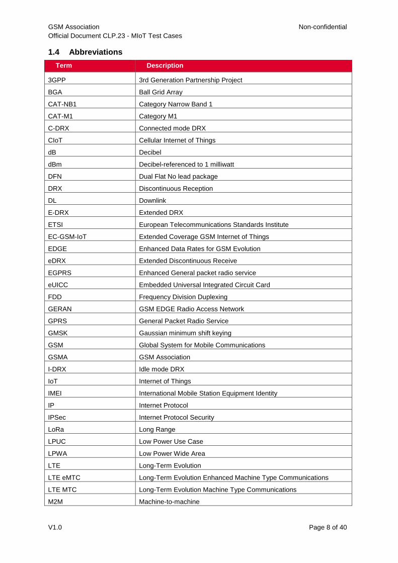
2.3 Device Capabilities
CAT-M1 Device Capability Transfer / Success - RRC Level -
CLP.23_2.3.1_TC_001
Purpose The purpose of this procedure is to transfer CAT-M1 Device capability information from the UE to E-UTRAN - RRC Level
Requirement under test
CLP.22_2.3.2_ REQ_001
Entry Criteria CAT-M1 Device is switched ON
CAT-M1 Device in RRC_CONNECTED State
Test Procedure eNodeB shall request the radio capability by sending UE Capability Enquiry Message to request UE radio access capability information.
CAT-M1 Device shall send the radio capability by sending RRC UE Capability Information Message
RRC UE Capability Information Message will include E-UTRAN parameter, Inter-RAT parameter and Radio Paging Information.
eNodeB will transfer the radio capability to MME.
Exit Criteria (Pass Criteria)
Verify that CAT-M1 Device sends UE Radio Device Capability (in RRC Level) in RRC UE Capability Information Message
CAT-M1 Device Capability Transfer / Success - NAS Level -
CLP.23_2.3.2_TC_001
Purpose The purpose of this procedure is to transfer CAT-M1 Device capability information from the UE to E-UTRAN - NAS Level
Requirement under test
CLP.22_2.3.2_ REQ_001
Entry Criteria CAT-M1 Device is switched ON
CAT-M1 Device in RRC_CONNECTED State
Test Procedure CAT-M1 Device initiates the Attach Procedure by sending Attach Request Message shall include UE Network Capability IE or MS Network Capability IE or both which includes with different CIoT EPS optimization that CAT-M1 Device Support
The Network responds to the CAT-M1 Device with Attach Accept Message that supports in “EPS Network Feature Support” in relation to CIoT EPS optimization that network supports.
Exit Criteria (Pass Criteria)
Verify that CAT-M1 Device sends UE Core Network Capability Information (in NAS Level) in Attach Request Message
CAT-NB1 device Capability Transfer / Success - RRC Level
CLP.23_2.3.3_TC_001
Purpose The purpose of this procedure is to transfer CAT-NB1 Device capability information from the UE to E-UTRAN - RRC Level
Requirement under test
CLP.22_2.3.2_ REQ_001
Entry Criteria CAT-NB1 Device is switched ON.
CAT-NB1 Device in RRC_CONNECTED State.

GSM Association Non-confidential
Official Document CLP.23 - MIoT Test Cases
V1.0 Page 19 of 40
Test Procedure eNodeB shall request the radio capability by sending UECapabilityEnquiry-NB Message to request UE radio access capability information.
CAT-NB1 Device shall send the radio capability by sending UECapabilityInformation-NB Message.
For CAT-NB1 device, UECapabilityInformation-NB Message shall include ue-Capability-Container-NB and ue-RadioPagingInfo-NB.
eNodeB will transfer the radio capability to MME.
Exit Criteria (Pass Criteria)
Verify that CAT-NB1 Device sends the device capabilities (in RRC Level) in UECapabilityInformation-NB Message
CAT-NB1 device Capability Transfer / Success - NAS Level
CLP.23_2.3.4_TC_001
Purpose The purpose of this procedure is to transfer CAT-NB1 Device capability information from the UE to E-UTRAN - NAS Level
Requirement under test
CLP.22_2.3.2_ REQ_001
Entry Criteria CAT-NB1 Device is switched ON.
Test Procedure CAT-NB1 Device initiates the Attach Procedure by sending Attach Request Message shall include UE Network Capability IE or MS Network Capability IE or both which includes different CIoT EPS optimizations that CAT-NB1 Device Supports.
The Network responds to the CAT-NB1 Device with Attach Accept Message that supports in “EPS Network Feature Support” in relation to CIoT EPS optimization that network supports.
Exit Criteria (Pass Criteria)
Verify that CAT-NB1 Device sends the device capabilities (in NAS Level) in Attach Request Message
2.4 Data Transfer and Throughput
CAT M1 Data Transfer and Throughput with Control Plane CIoT EPS
Optimizations - CLP.23_2.4.1_TC_001
Purpose The purpose of this procedure is to verify the data transfer with Control Plane CIoT EPS Optimizations
Requirement under test
CLP.22_2.4.2_ REQ_001
Entry Criteria CAT-M1 Device is switched ON
CAT-M1 Device in RRC_CONNECTED State
Test Procedure The uplink user data via the control plane, the CAT-M1 Device initiates the procedure by sending the ESM DATA TRANSPORT Message including the user data to be sent in the User data container IE.
If the downlink user data will transfer by the network will send the ESM DATA TRANSPORT message. When receiving the ESM DATA TRANSPORT message, the UE forwards the contents of the User data container IE to the upper layers.
Check the data transfer in different radio conditions (Near and Centre Cell Conditions) in relation to the different Modulation scheme.

GSM Association Non-confidential
Official Document CLP.23 - MIoT Test Cases
V1.0 Page 20 of 40
Exit Criteria (Pass Criteria)
Verify that CAT-M1 Device sends the data traffic in the uplink and the downlink direction via the control plane. The pass criteria for the throughput values is to be agreed between the CAT-M1 Device Manufacturer and the Mobile Network Operator. This requirement and respective test cases agreed between MNO and Vendors should be viewed as preliminary, and final throughput values for normal coverage mode will be consulted through the RAN 5 process.
CAT-M1 Data Transfer and Throughput with User Plane CIoT EPS
Optimizations - CLP.23_2.4.2_TC_001
Purpose The purpose of this procedure is to verify the data transfer with User Plane CIoT EPS Optimizations
Requirement under test
CLP.22_2.4.2_ REQ_001
Entry Criteria CAT-M1 Device is switched ON
CAT-M1 Device in RRC_CONNECTED State
If the CAT-M1 Device indicates support of User Plane CIoT EPS optimization then it shall also indicate support of S1-U Data Transfer
Test Procedure The uplink and the downlink user data are transfer using DRB’s (Data Radio Bearers) in RRC _CONNECTED State with S1-U data transfer.
Check the data transfer in different radio conditions (Near, Centre and Edge Cell Conditions) in relation to the different Modulation scheme.
Exit Criteria (Pass Criteria)
Verify that CAT-M1 Device sends the data traffic in the uplink and the downlink direction via S1-U data transfer. The pass criteria for the throughput values is to be agreed between the CAT-M1 Device Manufacturer and the Mobile Network Operator. This requirement and respective test cases agreed between MNO and Vendors should be viewed as preliminary, and final throughput values for normal coverage mode will be consulted through the RAN 5 process.
CAT-NB1 Device Data Transfer and Throughput with Control Plane
CIoT EPS Optimizations CLP.23_2.4.3_TC_001
Purpose The purpose of this procedure is to verify the data transfer with Control Plane CIoT EPS Optimizations.
Requirement under test
CLP.22_2.4.2_ REQ_001
Entry Criteria CAT-NB1 Device shall be configured to support “Control Plane CIoT EPS Optimizations”.
CAT-NB1 Device in RRC_CONNECTED State.
Test Procedure The uplink user data via the control plane, the CAT-NB1 Device initiates the procedure by sending the ESM DATA TRANSPORT Message including EPS bearer identity and the user data.
If the downlink user data will transfer by the network will send the ESM DATA TRANSPORT message. When receiving the ESM DATA TRANSPORT message, the UE forwards the contents of the User data container IE to the upper layers.
Check the data transfer in different radio conditions (Near and Centre Cell Conditions) in relation to the different Modulation scheme.

GSM Association Non-confidential
Official Document CLP.23 - MIoT Test Cases
V1.0 Page 21 of 40
Exit Criteria (Pass Criteria)
Verify that CAT-NB1 Device sends the data traffic in the uplink and the downlink direction and document the throughput values achieved. The pass criteria for the throughput values is to be agreed between the CAT-NB1 Device Manufacturer and the Mobile Network Operator. This requirement and respective test cases agreed between MNO and Vendors should be viewed as preliminary, and final throughput values for normal coverage mode will be consulted through the RAN 5 process.
CAT-NB1 Device Data Transfer and Throughput with User Plane CIoT
EPS Optimizations CLP.23_2.4.4_TC_001
Purpose The purpose of this procedure is to verify the data transfer with User Plane CIoT EPS Optimizations
Requirement under test
CLP.22_2.4.2_ REQ_001
Entry Criteria CAT-NB1 Device and networks shall be configured to support “Control Plane CIoT EPS Optimizations” and “User Plane CIoT EPS Optimizations”.
The CAT-NB1 Device and networks shall also indicate support “S1-U Data Transfer “.
CAT-NB1 Device is in RRC_CONNECTED State and user plane radio bears have been set up.
Test Procedure The uplink and the downlink user data are transfer using DRB’s (Data Radio Bearers) in RRC _CONNECTED State with S1-U data transfer.
Check the data transfer in different radio conditions (Near, Centre and Edge Cell Conditions) in relation to the different Modulation scheme.
Exit Criteria (Pass Criteria)
Verify that CAT-NB1 Device sends the data traffic in the uplink and the downlink direction. The pass criteria for the throughput values is to be agreed between the CAT-NB1 Device Manufacturer and the Mobile Network Operator. This requirement and respective test cases agreed between MNO and Vendors should be viewed as preliminary, and final throughput values for normal coverage mode will be consulted through the RAN 5 process.
2.5 Mobility
CAT-M1 Device Cell Reselection Procedure - CLP.23_2.5.1_TC_001
Purpose To verify that CAT-M1 device could successfully perform Cell Reselection Procedure with CIoT EPS Optimizations
Requirement under test
CLP.22_2.5.1_ REQ_001
Entry Criteria CAT-M1 Device is configured with “CIoT EPS Optimizations” in “Preferred and
Supported Network Behaviour”
CAT-M1 Device in RRC_IDLE State in Cell#1
Two EUTRAN Cell: Cell#1 (Serving Cell) & Cell#2 (Neighbouring Cell) and the
network are configured to support “CIoT EPS Optimizations”
Test Procedure Change the Radio conditions, CAT-M1 Device detects the new cell Cell#2 with re-selection criteria are met for this cell and ranked as the best cell.
Cell-ranking criterion Rs for Serving Cell and Rn for Neighbouring Cell is defined in the clause 5.2.4.6 of 3GPP TS 36.304
CAT-M1 Device reselects the new cell Cell#2 and starts to reads MIB, SIB1, SIB2
and check that “CIoT EPS Optimizations” is broadcast in EUTRAN Cell.

GSM Association Non-confidential
Official Document CLP.23 - MIoT Test Cases
V1.0 Page 22 of 40
Exit Criteria (Pass Criteria)
Verify that CAT-M1 Device performed Cell Reselection with New Cell Cell#2
CAT-M1 Device Handover Procedure with CIoT EPS Optimization -
CLP.23_2.5.2_TC_001
Purpose To verify that CAT-M1 device could successfully perform the handover procedure with CIoT EPS Optimization
Requirement under test
CLP.22_2.5.1_ REQ_002
Entry Criteria CAT-M1 Device are configured with CIoT EPS Optimizations that supports in “Preferred and Supported Network Behaviour”
CAT-M1 is Switched ON
Two EUTRAN Cell: Cell#1 & Cell#2 and the network are configured to support “CIoT EPS Optimizations”
Test Procedure CAT-M1 Device will perform Attach Procedure in Cell#1 with CIoT EPS Optimizations.
CAT-M1 Device will perform some data transfer on EPS bearer so that CAT-M1 Device will be in RRC_CONNECTED State
Change the Radio conditions to make Cell#2 better ranked than Cell#1 so that CAT-M1 Device will perform the measurement and sends the measurement report for an event when the radio conditions are met.
CAT-M1 Device does the handover successful to second cell (Cell#2).
After the handover is successful, CAT-M1 Device initiates a Tracking Area Update Procedure to synchronization the Bearer Context Status when supports CIoT EPS Optimizations
The Network shall then indicate the EPS bearer status to the UE in the Tracking Area Update Accept Message and the UE shall locally release any non-transferred bearer.
Exit Criteria (Pass Criteria)
Verify that CAT-M1 Device performed the handover successfully in Cell#2 and successfully initiate a Tracking Area Update Procedure to synchronization the Bearer Context Status.
CAT-NB1 device Intra-Frequency Cell Reselection
CLP.23_2.5.3_TC_001
Purpose The purpose of this procedure is to verify the CAT-NB1 device could complete the cell reselection within the intra-Frequency NB-IoT cells under RRC-Idle mode.
Requirement under test
CLP.22_2.5.1_REQ_001
Entry Criteria CAT-NB1 device shall be configured to support “Control Plane CIoT EPS Optimization”.
CAT-NB1 device is in RRC-Connected mode.
One Intra-Frequency NB-IoT neighbour cell is available.
GSM Association Non-confidential
Official Document CLP.23 - MIoT Test Cases
V1.0 Page 23 of 40
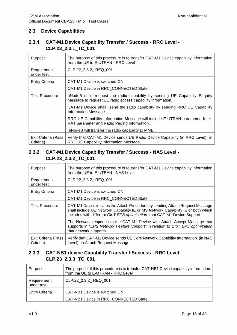
Test Procedure CAT-NB1 device has already received the SystemInformationBlockType3-NB/SystemInformationBlockType4-NB for intra-frequency cell reselection.
CAT-NB1 device goes to RRC_Idle mode after receiving RRCConnectionRelease-NB message.
The serving cell fulfils Srxlev > SIntraSearchP, the CAT-NB1 device may choose not to perform intra-frequency measurements.
Adjust RSRP of the serving cell, and make the Srxlev < SIntraSearchP.
The CAT-NB1 device shall perform intra-frequency measurements.
Adjust the RSRP of neighbour cell to good condition.
Exit Criteria CAT-NB1 device successfully completes the cell reselection to the intra-Frequency neighbour cell according the section 5.2.4.6 and section 5.24.2a of 3GPP 36.304.
CAT-NB1 device Inter-Frequencies Cell Reselection
CLP.23_2.5.4_TC_001
Purpose The purpose of this procedure is to verify the CAT-NB1 device could complete the cell reselection within the inter-Frequencies NB-IoT cells under RRC-Idle mode.
Requirement under test
CLP.22_2.5.1_REQ_001
Entry Criteria CAT-NB1 device shall be configured to support “Control Plane CIoT EPS Optimization”.
CAT-NB1 device is in RRC-Idle mode.
Two Inter-Frequencies NB-IoT cells are available.
Test Procedure CAT-NB1 device has already received the SystemInformationBlockType5-NB for inter-frequencies cell reselection.
CAT-NB1 device goes to RRC_Idle mode after receiving RRCConnectionRelease-NB message.
The serving cell fulfils Srxlev > SnonIntraSearchP, the CAT-NB1 device may choose not to perform intra-frequency measurements.
Adjust the RSRP of the serving cell, and make the Srxlev < SnonIntraSearchP.
The CAT-NB1 device shall perform inter-frequencies measurements.
Adjust the RSRP of neighbour cell to good condition.
Exit Criteria CAT-NB1 device successfully completes the cell reselection to the inter-Frequencies neighbour cell according the section 5.2.4.6 and section 5.24.2a of 3GPP 36.304.
CAT-NB1 device Cell Redirection CLP.23_2.5.5_TC_001
Purpose The purpose of this procedure is to verify the CAT-NB1 device could complete redirection to another NB-IoT cells when leaving RRC-Connected Mode to RRC-Idle Mode.
Requirement under test
CLP.22_2.5.1_REQ_001
Entry Criteria CAT-NB1 device shall be configured to support “Control Plane CIoT EPS Optimization”.
CAT-NB1 device is in RRC-Connected Mode.
The NB-IoT cell with the target frequency is in a good condition.

GSM Association Non-confidential
Official Document CLP.23 - MIoT Test Cases
V1.0 Page 24 of 40
Test Procedure CAT-NB1 device receives the RRCConnectionRelease-NB message with target frequency contained in “redirectedCarrierInfo IE”.
CAT-NB1 device goes to RRC_Idle Mode and starts to search for the NB-IoT cell on the target frequency.
CAT-NB1 device successfully camps on the target frequency NB-IoT cell.
Exit Criteria CAT-NB1 device successfully completes the redirection to the target frequency NB-IoT cell.
2.6 Suspend/Resume
CAT-M1 Device Suspend Procedure with User Plane CIoT EPS
Optimizations - CLP.23_2.6.1_TC_001
Purpose To verify that CAT-M1 device could successfully perform the suspend procedure
Requirement under test
CLP.22_2.6.2_ REQ_001
Entry Criteria CAT-M1 Device is configured with “User Plane CIoT EPS Optimizations” in “Preferred and Supported Network Behaviour”
CAT-M1 Device is Switched ON
The network is configured to support “User Plane CIoT EPS Optimizations”
Test Procedure The eNodeB transmits an RRC Connection Release Message to release RRC connection and move CAT-M1 Device in RRC_IDLE state.
RRC Connection Release Message shall be included with “resumeIdentity” and “release cause: rrc-Suspend”
Exit Criteria (Pass Criteria)
CAT-M1 Device will store resumeIdentity during RRC connection Release
CAT-M1 Device Resume Procedure with User Plane CIoT EPS
Optimizations - TS23_2.6.2_TC_001
Purpose To verify that CAT-M1 device could successfully perform the resume procedure
Requirement under test
TS.22_2.6.2_REQ_002
Entry Criteria CAT-M1 Device is configured with “User Plane CIoT EPS Optimizations” in “Preferred and Supported Network Behaviour”
CAT-M1 Device in RRC_IDLE State
The network is configured to support “User Plane CIoT EPS Optimizations”
GSM Association Non-confidential
Official Document CLP.23 - MIoT Test Cases
V1.0 Page 25 of 40
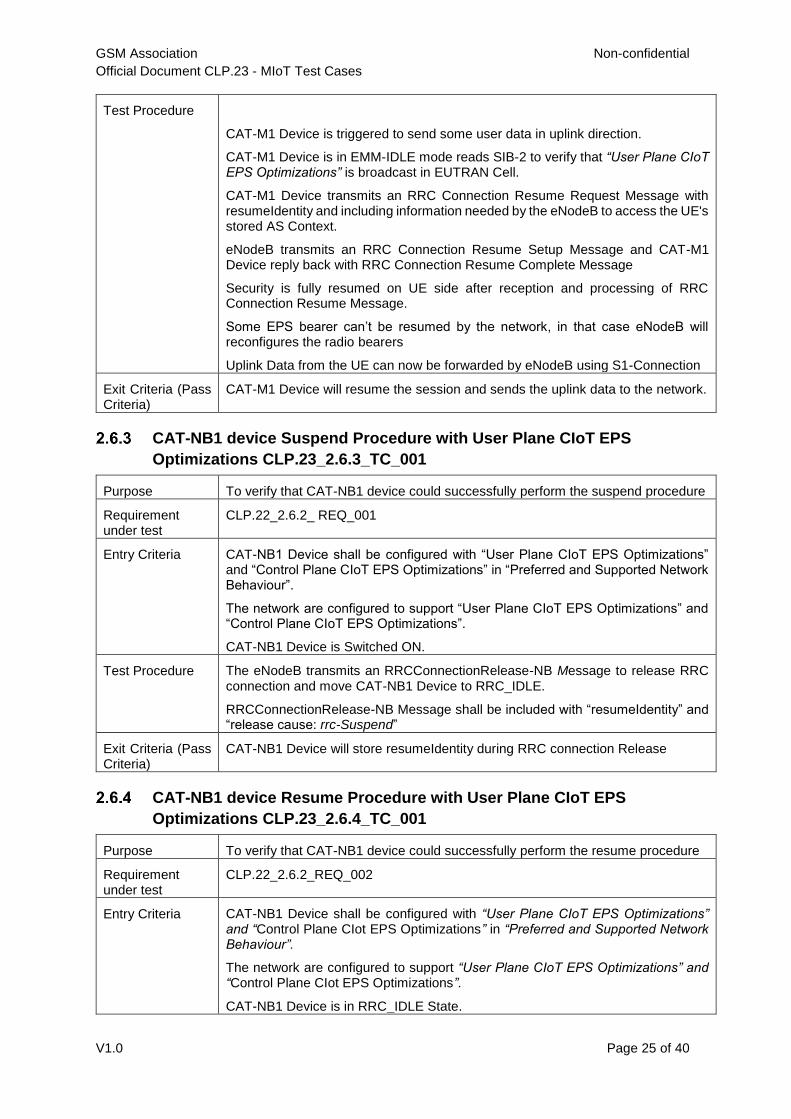
Test Procedure
CAT-M1 Device is triggered to send some user data in uplink direction.
CAT-M1 Device is in EMM-IDLE mode reads SIB-2 to verify that “User Plane CIoT EPS Optimizations” is broadcast in EUTRAN Cell.
CAT-M1 Device transmits an RRC Connection Resume Request Message with resumeIdentity and including information needed by the eNodeB to access the UE's stored AS Context.
eNodeB transmits an RRC Connection Resume Setup Message and CAT-M1 Device reply back with RRC Connection Resume Complete Message
Security is fully resumed on UE side after reception and processing of RRC Connection Resume Message.
Some EPS bearer can’t be resumed by the network, in that case eNodeB will reconfigures the radio bearers
Uplink Data from the UE can now be forwarded by eNodeB using S1-Connection
Exit Criteria (Pass Criteria)
CAT-M1 Device will resume the session and sends the uplink data to the network.
CAT-NB1 device Suspend Procedure with User Plane CIoT EPS
Optimizations CLP.23_2.6.3_TC_001
Purpose To verify that CAT-NB1 device could successfully perform the suspend procedure
Requirement under test
CLP.22_2.6.2_ REQ_001
Entry Criteria CAT-NB1 Device shall be configured with “User Plane CIoT EPS Optimizations” and “Control Plane CIoT EPS Optimizations” in “Preferred and Supported Network Behaviour”.
The network are configured to support “User Plane CIoT EPS Optimizations” and “Control Plane CIoT EPS Optimizations”.
CAT-NB1 Device is Switched ON.
Test Procedure The eNodeB transmits an RRCConnectionRelease-NB Message to release RRC connection and move CAT-NB1 Device to RRC_IDLE.
RRCConnectionRelease-NB Message shall be included with “resumeIdentity” and “release cause: rrc-Suspend”
Exit Criteria (Pass Criteria)
CAT-NB1 Device will store resumeIdentity during RRC connection Release
CAT-NB1 device Resume Procedure with User Plane CIoT EPS
Optimizations CLP.23_2.6.4_TC_001
Purpose To verify that CAT-NB1 device could successfully perform the resume procedure
Requirement under test
CLP.22_2.6.2_REQ_002
Entry Criteria CAT-NB1 Device shall be configured with “User Plane CIoT EPS Optimizations” and “Control Plane CIot EPS Optimizations” in “Preferred and Supported Network Behaviour”.
The network are configured to support “User Plane CIoT EPS Optimizations” and “Control Plane CIot EPS Optimizations”.
CAT-NB1 Device is in RRC_IDLE State.

GSM Association Non-confidential
Official Document CLP.23 - MIoT Test Cases
V1.0 Page 26 of 40
Test Procedure CAT-NB1 Device is triggered to send some data in uplink
CAT-NB1 Device transmits an RRCConnectionResumeRequest-NB Message with resumeIdentity and including information needed by the eNodeB to access the UE's stored AS Context.
In case any EPS bearers can’t be resumed by the network, eNodeB will reconfigure the radio bearers via RRCConnectionReconfiguration-NB Messages.
Uplink Data from the UE can now be forwarded by eNodeB.
Exit Criteria (Pass Criteria)
CAT-NB1 Device will resume the session and sends the uplink data to the network.
3 Enhanced Coverage
3.1 Random Access
NPRACH configuration in Random Access - CLP.23_3.1.1_TC_001
Purpose To verify that the category NB1 UE could properly execute the random access procedure defined in clause 5.1 in TS 36.321 [15] using the NPRACH configuration contained in NPRACH-ConfigSIB-NB in TS 36.331 [16]
Requirement under test
TS.22_3.1.2_REQ_001
Entry Criteria UE is powered on and in RRC_IDLE mode.
Network configures 3 coverage levels.
Choose a proper location for CAT-NB1 Device to ensure the Device is in coverage level 0/1/2. The test is performed respectively for each coverage level.
Test Procedure The Network sends Paging message.
CAT-NB1 Device transmits Random Access Preamble using NPRACH resource corresponding to current enhanced coverage level.
The Network sends Random Access Response message.
CAT-NB1 Device transmits Msg3.
Exit Criteria UE should send Random Access Preamble using proper resource.
PRACH configuration in Random Access - CLP.23_3.1.2_TC_001
Purpose To verify that the category CAT-M1 UE could properly execute the random access procedure defined in clause 5.1 in TS 36.321 [15] using the PRACH configuration contained in PRACH-ConfigSIB in TS 36.331 [16]
Requirement under test
CLP.22_3.1.2_REQ_001
Entry Criteria UE is powered on and in RRC_IDLE mode.
Network configures 3 coverage levels.
Choose a proper location for CAT-M1 Device to ensure the Device is in coverage level 0/1/2. The test is performed respectively for each coverage level.
GSM Association Non-confidential
Official Document CLP.23 - MIoT Test Cases
V1.0 Page 27 of 40
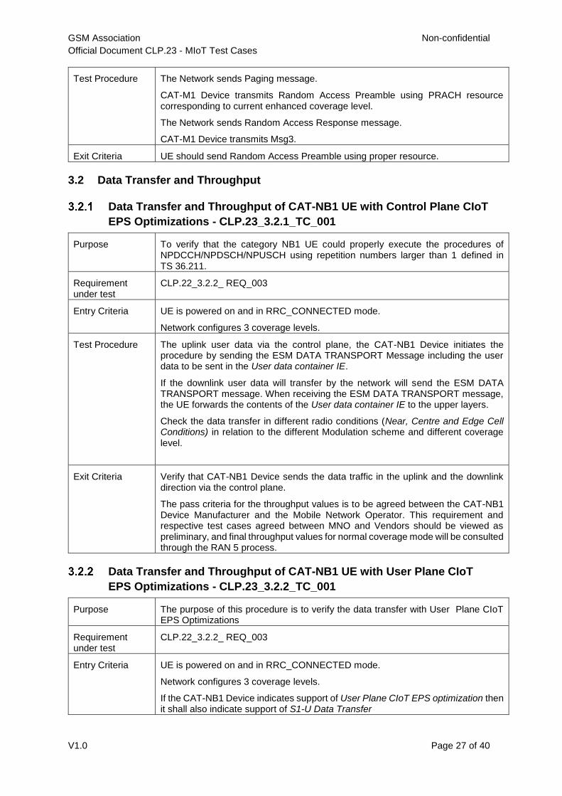
Test Procedure The Network sends Paging message.
CAT-M1 Device transmits Random Access Preamble using PRACH resource corresponding to current enhanced coverage level.
The Network sends Random Access Response message.
CAT-M1 Device transmits Msg3.
Exit Criteria UE should send Random Access Preamble using proper resource.
3.2 Data Transfer and Throughput
Data Transfer and Throughput of CAT-NB1 UE with Control Plane CIoT
EPS Optimizations - CLP.23_3.2.1_TC_001
Purpose To verify that the category NB1 UE could properly execute the procedures of NPDCCH/NPDSCH/NPUSCH using repetition numbers larger than 1 defined in TS 36.211.
Requirement under test
CLP.22_3.2.2_ REQ_003
Entry Criteria UE is powered on and in RRC_CONNECTED mode.
Network configures 3 coverage levels.
Test Procedure The uplink user data via the control plane, the CAT-NB1 Device initiates the procedure by sending the ESM DATA TRANSPORT Message including the user data to be sent in the User data container IE.
If the downlink user data will transfer by the network will send the ESM DATA TRANSPORT message. When receiving the ESM DATA TRANSPORT message, the UE forwards the contents of the User data container IE to the upper layers.
Check the data transfer in different radio conditions (Near, Centre and Edge Cell Conditions) in relation to the different Modulation scheme and different coverage level.
Exit Criteria Verify that CAT-NB1 Device sends the data traffic in the uplink and the downlink direction via the control plane.
The pass criteria for the throughput values is to be agreed between the CAT-NB1 Device Manufacturer and the Mobile Network Operator. This requirement and respective test cases agreed between MNO and Vendors should be viewed as preliminary, and final throughput values for normal coverage mode will be consulted through the RAN 5 process.
Data Transfer and Throughput of CAT-NB1 UE with User Plane CIoT
EPS Optimizations - CLP.23_3.2.2_TC_001
Purpose The purpose of this procedure is to verify the data transfer with User Plane CIoT EPS Optimizations
Requirement under test
CLP.22_3.2.2_ REQ_003
Entry Criteria UE is powered on and in RRC_CONNECTED mode.
Network configures 3 coverage levels.
If the CAT-NB1 Device indicates support of User Plane CIoT EPS optimization then it shall also indicate support of S1-U Data Transfer

GSM Association Non-confidential
Official Document CLP.23 - MIoT Test Cases
V1.0 Page 28 of 40
Test Procedure The uplink and the downlink user data are transfer using DRB’s (Data Radio Bearers) in RRC _CONNECTED State with S1-U data transfer.
Check the data transfer in different radio conditions (Near, Centre and Edge Cell Conditions) in relation to the different Modulation scheme.
Exit Criteria (Pass Criteria)
Verify that CAT-NB1 Device sends the data traffic in the uplink and the downlink direction via S1-U data transfer.
The pass criteria for the throughput values is to be agreed between the CAT-NB1 Device Manufacturer and the Mobile Network Operator. This requirement and respective test cases agreed between MNO and Vendors should be viewed as preliminary, and final throughput values for normal coverage mode will be consulted through the RAN 5 process.
Data Transfer and Throughput of CAT-M1 UE - CLP.23_3.2.3_TC_001
Purpose The purpose of this procedure is to verify the data transfer with Cat-M1
Requirement under test
CLP.22_3.2.2_ REQ_001
Entry Criteria UE is powered on and in RRC_CONNECTED mode.
Network configures 3 coverage levels.
If the CAT-M1 Device indicates support of User Plane CIoT EPS optimization then it shall also indicate support of S1-U Data Transfer
Test Procedure The uplink and the downlink user data are transfer using DRB’s (Data Radio Bearers) in RRC _CONNECTED State with S1-U data transfer.
Check the data transfer in different radio conditions (Edge of cell Conditions invoking EC mode A and mode B) in relation to the different Modulation scheme.
Exit Criteria (Pass Criteria)
Verify that CAT-M1 Device sends the data traffic in the uplink and the downlink direction via S1-U data transfer.
The pass criteria for the throughput values is to be agreed between the CAT-M1 Device Manufacturer and the Mobile Network Operator. This requirement and respective test cases agreed between MNO and Vendors should be viewed as preliminary, and final throughput values for normal coverage mode will be consulted through the RAN 5 process.
Data Transfer and Throughput of CAT-M1 UE with Control Plane CIoT
EPS Optimizations - CLP.23_3.2.4_TC_001
Purpose The purpose of this procedure is to verify the data transfer with Cat-M1
Requirement under test
CLP.22_3.2.2_ REQ_001
Entry Criteria UE is powered on and in RRC_CONNECTED mode.
Network configures 2 coverage levels for UE supporting CE Mode A and 4 coverage levels for UE supporting CE Mode B.

GSM Association Non-confidential
Official Document CLP.23 - MIoT Test Cases
V1.0 Page 29 of 40
Test Procedure The uplink user data via the control plane, the CAT-M1 Device initiates the procedure by sending the ESM DATA TRANSPORT Message including the user data to be sent in the User data container IE.
If downlink user datal to be transferred, the network will send the ESM DATA TRANSPORT message. When receiving the ESM DATA TRANSPORT message, the UE forwards the contents of the User data container IE to the upper layers.
Check the data transfer in different radio conditions (Near, Centre and Edge Cell Conditions) in relation to the different Modulation scheme and different coverage level.
Exit Criteria Verify that CAT-M1 Device sends the data traffic in the uplink and the downlink direction via the control plane.
The pass criteria for the throughput values is to be agreed between the CAT-M1 Device Manufacturer and the Mobile Network Operator. This requirement and respective test cases agreed between MNO and Vendors should be viewed as preliminary, and final throughput values for normal coverage mode will be consulted through the RAN 5 process.
4 Power Test Cases
This section should be read in conjunction with CLP22 v1.0, MIoT Requirements document.
The Conformance requirements contained with Section 4 of that document apply.
4.1 PSM Operation
PSM Request and Activation - CLP.23_4.1.1_TC_001
Purpose To verify that the DUT could successfully request PSM during attach.
Requirement under test
CLP.22_4.1_REQ_001; CLP.22_4.1_REQ_005
Entry Criteria DUT is configured to use Power Saving Mode
DUT is powered off
Test Procedure Power on DUT.
DUT initiates the Attach procedure by sending the “Attach Request” message that contains the “T3324 and T3412 Values”
The network responds to the DUT with “Attach Accept” message that contains the “T3324 and T3412 values”.
DUT completes the Attach procedure by sending the “Attach Complete” message.
DUT releases the connection.
Change the values of T3412 and T3324 in the DUT.
Repeat steps 1-5
Exit Criteria DUT shall contain “T3324 Value” in Attach Request in order to request PSM in step 2
In Step 7 the DUT will send Attach Request message with updated timer values

GSM Association Non-confidential
Official Document CLP.23 - MIoT Test Cases
V1.0 Page 30 of 40
MT Data in PSM State - CLP.23_4.1.2_TC_001
Purpose To verify that the DUT could successfully monitor Paging message and receive MT user data when T3324 Timer running and then enter PSM again when T3324 timer expires.
Requirement under test
CLP.22_4.1_REQ_001
Entry Criteria DUT is configured to use Power Saving Mode
DUT is powered off
Test Procedure Power on DUT.
DUT initiates the Attach procedure by sending the “Attach Request” message that contains the “T3324 Value”
The network responds to the DUT with “Attach Accept” message that contains the “T3324 value”.
DUT completes the Attach procedure by sending the “Attach Complete” message.
DUT releases the connection.
Initiate MT user data before T3324 expires.
Stop MT data. DUT releases the connection, enters in idle state and starts T3324 timer.
Initiate MT user data after T3324 expires.
Exit Criteria DUT shall respond to the paging message, establish connection and receive MT data in step 6
DUT shall not give any response in step 8.
MO Data in PSM State - CLP.23_4.1.3_TC_001
Purpose To verify that the DUT could successfully deactivate PSM at any time for the transfer of mobile originated user data.
Requirement under test
CLP.22_4.1_REQ_001; CLP.22_4.1_REQ_007
Entry Criteria DUT is configured to use Power Saving Mode
DUT is powered off
Test Procedure Power on DUT.
DUT initiates the Attach procedure by sending the “Attach Request” message that contains the “T3324 Value”,
The network responds to the DUT with “Attach Accept” message that contains the “T3324 value”.
DUT completes the Attach procedure by sending the “Attach Complete” message.
DUT releases the connection. Wait for T3324 Timer to expire.
Check CAT-M1, CAT-NB1 device entered PSM after expiry of T3324 by attempting to page the DUT
Initiate MO user data after T3324 expires.

GSM Association Non-confidential
Official Document CLP.23 - MIoT Test Cases
V1.0 Page 31 of 40
Exit Criteria Check DUT enters PSM after the expiry of T3324 in step 5
DUT shall deactivate PSM , establish connection and send MO data in step 7
Periodic Tracking/Routing Area Update - CLP.23_4.1.4_TC_001
Purpose To verify that the UE successfully performs a Periodic Tracking/Routing Area Update procedure after the expiry of the T3412/T3312 timer when PSM is activated.
Requirement under test
CLP.22_4.1_REQ_001
Entry Criteria DUT is configured to use Power Saving Mode
DUT is powered off
Test Procedure Power on DUT.
DUT initiates the Attach procedure by sending the “Attach Request” message that contains the “T3324 Value”,
The network responds to the DUT with “Attach Accept” message that contains the “T3324 value” for PSM and “T3412 Value” for Periodic TAU or “T3312 Value” for Periodic RAU
DUT completes the Attach procedure by sending the “Attach Complete” message.
DUT releases the connection and enters in idle state. DUT enters PSM after T3324 expires.
After the expiry of the T3412 or T3312 timer, DUT sends a TRACKING AREA UPDATE REQUEST or ROUTING AREA UPDATE REQUEST message.
The network responds to the DUT with TRACKING AREA UPDATE ACCEPT or ROUTING AREA UPDATE ACCEPT message that contains the “T3324 value”
DUT completes the TAU or RAU procedure by sending the TRACKING AREA UPDATE COMPLETE (if GUTI allocated) message or ROUTING AREA UPDATE COMPLETE message (if P-TMSI changed)
DUT releases the connection and enters in idle state. DUT enters PSM after T3324 expires.
Initiate MT user data after T3324 expires
Exit Criteria DUT should sends a TRACKING AREA UPDATE REQUEST with EPS update type set to "periodic updating" or ROUTING AREA UPDATE REQUEST message with update type set to "periodic updating".
DUT shall include “T3324 value” IE in step 2 & 6.
Check DUT enters PSM again after the expiry of T3324 in step 9
Reduced Current Drain in PSM- CLP.23_4.1.5_TC_001
Purpose To verify that the UE supports a reduced current drain when in Power Saving Mode
Requirement under test
CLP.22_4.1_REQ_003

GSM Association Non-confidential
Official Document CLP.23 - MIoT Test Cases
V1.0 Page 32 of 40
Entry Criteria The DUT battery is replaced with the “dummy battery”.
The dummy battery is connected to a combined DC power source and current measurement device.
The DC power source is configured to maintain a voltage equal to the Nominal Battery Voltage across the dummy battery terminals.
DUT is powered off
I-eDRX is disabled in DUT
All other radio's (WiFi/BT etc) in the device are switched off
Test Procedure DUT is configured to disable Power Saving Mode
Activate the DUT
Wait 3 minutes after DUT has completed registration.
In idle mode, record a minimum of 120 samples over a continuous 30 minute period, using ammeters or automated power monitors if available.
Calculate the average current drain from the measured samples, denoted by IPSM_Disabled.
Power off DUT.
DUT is configured to use Power Saving Mode, with sleep timer (T3412) set to at least 30 minutes.
Activate the DUT
Wait 3 minutes after DUT completed registration.
In PSM mode, record a minimum of 120 samples over a continuous 30 minute period, using ammeters or automated power monitors if available.
Calculate the average current drain from the measured samples, denoted by IPSM_Enabled
Exit Criteria The current drain in PSM (IPSM_Enabled) should be several orders of magnitude lower than the one in idle mode(IPSM_Disabled)
Periodic Tracking Area Update, T3412 - CLP.23_4.1.6_TC_001
Purpose To verify that the DUT accepts t3412 value from NW
Requirement under test
CLP.22_4.1_REQ_001; CLP.22_4.1_REQ_006
Entry Criteria DUT is configured to use Power Saving Mode
DUT is configured with preferred t3412 value (different from NW)
DUT is powered off

GSM Association Non-confidential
Official Document CLP.23 - MIoT Test Cases
V1.0 Page 33 of 40
Test Procedure Power on DUT.
DUT initiates the Attach procedure by sending the ATTACH REQUEST message that contains the “T3324 and T3412 Values”
The network responds to the DUT with “ATTACH ACCEPT message that contains the “T3324 value” and a different “T3412 value” for periodic TAU.
DUT completes the Attach procedure by sending the “ATTACH COMPLETE” message.
DUT releases the connection and enters in idle state. DUT enters PSM after T3324 expires.
After the expiry of the T3412 timer, DUT sends a TRACKING AREA UPDATE REQUEST message.
The network responds to the DUT with TRACKING AREA UPDATE ACCEPT message that contains the “T3324 and T3412 values”
DUT completes the TAU procedure by sending the TRACKING AREA UPDATE COMPLETE.
Exit Criteria DUT shall send Attach Request containing “T3324 Value” and a preferred “T3412 Value” in order to request PSM in step 2 and 6.
Check DUT accepts new Value for T3412 in ATTACH COMPLETE message in step 4.
Check DUT initiates TAU after expiry of T3412 in step 6.
4.2 I-eDRX Operation
eDRX Request and Activation - CLP.23_4.2.1_TC_001
Purpose To verify that the DUT could successfully request eDRX during attach and monitor Paging according to eDRX cycle and PTW (except EC-GSM).
Requirement under test
CLP.22_4.1_REQ_002; CLP.22_4.1_REQ_008; CLP.22_4.1_REQ_009
Entry Criteria Idle mode extended DRX is allowed in the serving cell.
DUT is configured to use eDRX
DUT is powered off
Test Procedure Power on DUT.
DUT initiates the Attach procedure by sending the “Attach Request” message that contains the “Extended DRX parameters” IE.
The network responds to the DUT with “Attach Accept” message that contains the “Extended DRX parameters” to indicate the eDRX cycle and PTW (except EC-GSM).
DUT completes the Attach procedure by sending the “Attach Complete” message.
DUT releases the connection.
Initiate MT user data and the network sends Paging message.
DUT responds to the Paging and receives the MT data.
Repeat steps 1-7 with a different value for “Extended DRX Parameter” IE
GSM Association Non-confidential
Official Document CLP.23 - MIoT Test Cases
V1.0 Page 34 of 40
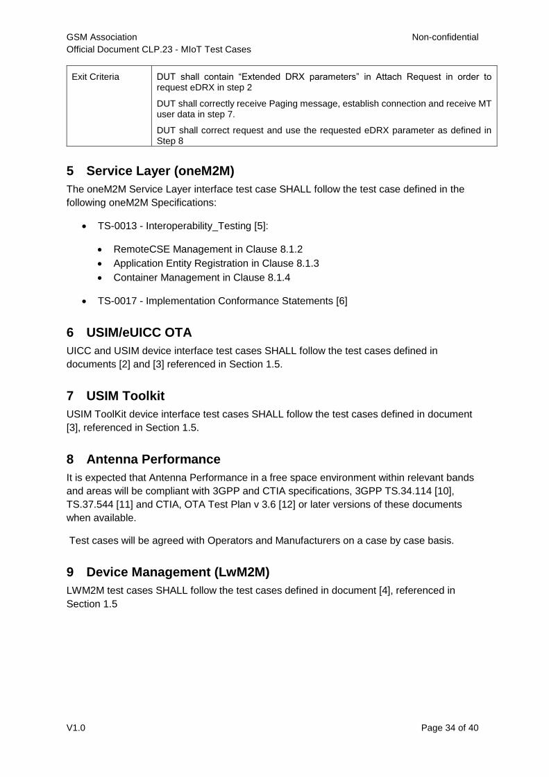
Exit Criteria DUT shall contain “Extended DRX parameters” in Attach Request in order to request eDRX in step 2
DUT shall correctly receive Paging message, establish connection and receive MT user data in step 7.
DUT shall correct request and use the requested eDRX parameter as defined in Step 8
5 Service Layer (oneM2M)
The oneM2M Service Layer interface test case SHALL follow the test case defined in the
following oneM2M Specifications:
TS-0013 - Interoperability_Testing [5]:
RemoteCSE Management in Clause 8.1.2
Application Entity Registration in Clause 8.1.3
Container Management in Clause 8.1.4
TS-0017 - Implementation Conformance Statements [6]
6 USIM/eUICC OTA
UICC and USIM device interface test cases SHALL follow the test cases defined in
documents [2] and [3] referenced in Section 1.5.
7 USIM Toolkit
USIM ToolKit device interface test cases SHALL follow the test cases defined in document
[3], referenced in Section 1.5.
8 Antenna Performance
It is expected that Antenna Performance in a free space environment within relevant bands
and areas will be compliant with 3GPP and CTIA specifications, 3GPP TS.34.114 [10],
TS.37.544 [11] and CTIA, OTA Test Plan v 3.6 [12] or later versions of these documents
when available.
Test cases will be agreed with Operators and Manufacturers on a case by case basis.
9 Device Management (LwM2M)
LWM2M test cases SHALL follow the test cases defined in document [4], referenced in
Section 1.5

GSM Association Non-confidential
Official Document CLP.23 - MIoT Test Cases
V1.0 Page 35 of 40
10 Mapping of Test Cases to Requirements
MioT Requirements Document Section
Requirement Test Case Comments
2 Basic Operation
CLP.22_2.1.2_REQ_001 CLP.23_2.1.1_TC_001 (CAT-M1)
CLP.23_2.1.2_TC_001 (CAT-NB1)
CLP.22_2.1.2_REQ_002 EC-GSM-IoT Test Cases to be defined when Manufacturer support is available.
CLP.22_2.2.2_REQ_001 CLP.23_2.2.1_TC_001 (CAT-M1)
CLP.23_2.2.2_TC_001 (CAT-M1)
CLP.23_2.2.3_TC_001 (CAT-M1)
CLP.23_2.2.5_TC_001 (CAT-NB1)
CLP.23_2.2.6_TC_001 (CAT-NB1)
CLP.23_2.2.7_TC_001 (CAT-NB1)
CLP.23_2.2.8_TC_001 (CAT-NB1)
CLP.22_2.2.2_ REQ_002 CLP.23_2.2.4_TC_001 (CAT-M1)
CLP.23_2.2.9_TC_001 (CAT-NB1)
CLP.22_2.2.2_ REQ_003 EC-GSM-IoT Test Cases to be defined when Manufacturer support is available.
CLP.22_2.2.2_ REQ_004 EC-GSM-IoT Test Cases to be defined when Manufacturer support is available.
CLP.22_2.3.2_ REQ_001 CLP.23_2.3.1_TC_001 (CAT-M1)
CLP.23_2.3.2_TC_001 (CAT-M1)
CLP.23_2.3.3_TC_001 (CAT-NB1)
CLP.23_2.3.4_TC_001 (CAT-NB1)
CLP.22_2.4.2_ REQ_001 CLP.23_2.4.1_TC_001 (CAT-M1)
CLP.23_2.4.2_TC_001 (CAT-M1)
CLP.23_2.4.3_TC_001 (CAT-NB1)
CLP.23_2.4.4_TC_001 (CAT-NB1)
CLP.22_2.4.2_REQ_002 EC-GSM-IoT Test Cases to be defined when Manufacturer support is available.
CLP22_2.4.2_REQ_003 To be agreed with Operator and Manufacturer
CLP.22_2.5.1_ REQ_001 CLP.23_2.5.1_TC_001 (CAT-M1)
CLP.23_2.5.3_TC_001 (CAT-NB1)
CLP.23_2.5.4_TC_001 (CAT-NB1)
CLP.23_2.5.5_TC_001 (CAT-NB1)
CLP.22_2.5.1_ REQ_002 CLP.23_2.5.2_TC_001 (CAT-M1)
CLP.22_2.5.1_ REQ_003 EC-GSM-IoT Test Cases to be defined when Manufacturer support is available.
CLP.22_2.6.2_ REQ_001 CLP.23_2.6.1_TC_001 (CAT-M1)

GSM Association Non-confidential
Official Document CLP.23 - MIoT Test Cases
V1.0 Page 36 of 40
MioT Requirements Document Section
Requirement Test Case Comments
CLP.23_2.6.3_TC_001 (CAT-NB1)
CLP.22_2.6.2_REQ_002 CLP.23_2.6.2_TC_001 (CAT-M1)
CLP.23_2.6.4_TC_001 (CAT-NB1)
3 Enhanced Coverage
CLP.22_3.1.2_ REQ_001 CLP.23_3.1.2_TC_001
CLP.22_3.1.2_ REQ_002 EC-GSM-IoT Test Cases to be defined when Manufacturer support is available.
CLP.22_3.2.2_ REQ_001 CLP.23_3.2.3_TC_001
CLP.23_3.2.4_TC_001
CLP.22_3.2.2_ REQ_002 EC-GSM-IoT Test Cases to be defined when Manufacturer support is available.
CLP.22_3.2.2_ REQ_003 CLP.23_3.2.1_TC_001 (CAT-NB1)
4 Power
Test Cases
CLP.22_4.1_REQ_001 CLP.23_4.1.1_TC_001
CLP.23_4.1.2_TC_001
CLP.23_4.1.3_TC_001
CLP.23_4.1.4_TC_001
CLP.23_4.1.6_TC_001
CLP.22_4.1_REQ_002 CLP.23_4.3.1_TC_001
CLP.22_4.1_REQ_003 CLP.23_4.1.5_TC_001
CLP.22_4.1_REQ_004 EC-GSM-IoT Test Cases to be defined when Manufacturer support is available.
CLP.22_4.1_REQ_005 CLP.23_4.1.1_TC_001
CLP.22_4.1_REQ_006 CLP.23_4.1.6_TC_001
CLP.22_4.1_REQ_007 CLP.23_4.1.3_TC_001
CLP.22_4.1_REQ_008 CLP.23_4.2.1_TC_001
CLP.22_4.1_REQ_009 CLP.23_4.2.1_TC_001
5 Service Layer (oneM2M)
CLP.22_5.3_REQ_001 The oneM2M Service Layer interface test case SHALL follow the test case defined in the following oneM2M Specifications: [5] TS-0013 - Interoperability_Testing: RemoteCSE Management in Clause 8.1.2 Application Entity Registration in Clause 8.1.3 Container Management in Clause 8.1.4 [6] TS-0017 - Implementation Conformance Statements
CLP.22_5.3_REQ_002 The oneM2M Service Layer interface test case SHALL follow
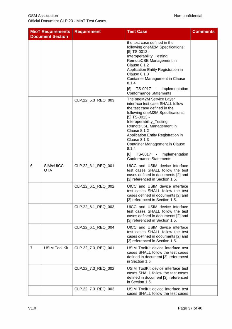
GSM Association Non-confidential
Official Document CLP.23 - MIoT Test Cases
V1.0 Page 37 of 40
MioT Requirements Document Section
Requirement Test Case Comments
the test case defined in the following oneM2M Specifications: [5] TS-0013 - Interoperability_Testing: RemoteCSE Management in Clause 8.1.2 Application Entity Registration in Clause 8.1.3 Container Management in Clause 8.1.4
[6] TS-0017 - Implementation Conformance Statements
CLP.22_5.3_REQ_003 The oneM2M Service Layer interface test case SHALL follow the test case defined in the following oneM2M Specifications: [5] TS-0013 - Interoperability_Testing: RemoteCSE Management in Clause 8.1.2 Application Entity Registration in Clause 8.1.3 Container Management in Clause 8.1.4
[6] TS-0017 - Implementation Conformance Statements
6 SIM/eUICC OTA
CLP.22_6.1_REQ_001 UICC and USIM device interface test cases SHALL follow the test cases defined in documents [2] and [3] referenced in Section 1.5.
CLP.22_6.1_REQ_002 UICC and USIM device interface test cases SHALL follow the test cases defined in documents [2] and [3] referenced in Section 1.5.
CLP.22_6.1_REQ_003 UICC and USIM device interface test cases SHALL follow the test cases defined in documents [2] and [3] referenced in Section 1.5.
CLP.22_6.1_REQ_004 UICC and USIM device interface test cases SHALL follow the test cases defined in documents [2] and [3] referenced in Section 1.5.
7 USIM Tool Kit CLP.22_7.3_REQ_001 USIM ToolKit device interface test cases SHALL follow the test cases defined in document [3], referenced in Section 1.5.
CLP.22_7.3_REQ_002 USIM ToolKit device interface test cases SHALL follow the test cases defined in document [3], referenced in Section 1.5
CLP.22_7.3_REQ_003 USIM ToolKit device interface test cases SHALL follow the test cases

GSM Association Non-confidential
Official Document CLP.23 - MIoT Test Cases
V1.0 Page 38 of 40
MioT Requirements Document Section
Requirement Test Case Comments
defined in document [3], referenced in Section 1.5
8 Antenna Performance
It is expected that Antenna Performance in a free space environment within relevant bands and areas will be complaint with 3GPP and CTIA specifications where/when they are available.
Test cases will be agreed with Operators and Manufacturers on a case by case basis.
9 Device Management (LwM2M)
CLP.22_9.2_REQ_001 LWM2M test cases SHALL follow the test cases defined in document [4], referenced in Section 1.5.
CLP.22_9.2_REQ_002 LWM2M test cases SHALL follow the test cases defined in document [4], referenced in Section 1.5.
CLP.22_9.2_REQ_003 LWM2M test cases SHALL follow the test cases defined in document [4], referenced in Section 1.5.
CLP.22_9.2_REQ_004 LWM2M test cases SHALL follow the test cases defined in document [4], referenced in Section 1.5.
CLP.22_9.2_REQ_005 LWM2M test cases SHALL follow the test cases defined in document [4], referenced in Section 1.5.
CLP.22_9.2_REQ_006 LWM2M test cases SHALL follow the test cases defined in document [4], referenced in Section 1.5.
CLP.22_9.2_REQ_007 LWM2M test cases SHALL follow the test cases defined in document [4], referenced in Section 1.5.
CLP.22_9.2_REQ_008 LWM2M test cases SHALL follow the test cases defined in document [4], referenced in Section 1.5.
CLP.22_9.2_REQ_009 LWM2M test cases SHALL follow the test cases defined in document [4], referenced in Section 1.5.
CLP.22_9.2_REQ_010 LWM2M test cases SHALL follow the test cases defined in document [4], referenced in Section 1.5.
CLP.22_9.2_REQ_011 LWM2M test cases SHALL follow the test cases defined in document [4], referenced in Section 1.5.
CLP.22_9.2_REQ_012 LWM2M test cases SHALL follow the test cases defined in document [4], referenced in Section 1.5.

GSM Association Non-confidential
Official Document CLP.23 - MIoT Test Cases
V1.0 Page 39 of 40
MioT Requirements Document Section
Requirement Test Case Comments
CLP.22_9.2_REQ_013 LWM2M test cases SHALL follow the test cases defined in document [4], referenced in Section 1.5.
CLP.22_9.2_REQ_014 LWM2M test cases SHALL follow the test cases defined in document [4], referenced in Section 1.5.

GSM Association Non-confidential
Official Document CLP.23 - MIoT Test Cases
V1.0 Page 40 of 40
Annex A Document Management
A.1 Document History
Version Date Brief Description of Change Approval
Authority
Editor /
Company
1.0 18
November
2016
New PRD (CLP23 v0.1). TCJWG/PSMC
David Hills
A.2 Other Information
Type Description
Document Owner Test and Certification Joint Working Group (TCJWG)
Editor / Company David Hills, GSMA
It is our intention to provide a quality product for your use. If you find any errors or omissions,
please contact us with your comments. You may notify us at [email protected]
Your comments or suggestions & questions are always welcome.