Embed Size (px)
Citation preview

MINUTES OF
IOWA DOT SPECIFICATION COMMITTEE MEETING
May 9, 2019 Members Present: Darwin Bishop District 3 - Construction Roger Boulet District 6 - Materials Donna Buchwald Local Systems Bureau Mark Dunn Contracts & Specifications Bureau Daniel Harness Design Bureau Eric Johnsen, Secretary Contracts & Specifications Bureau Wes Musgrove Construction & Materials Bureau Mike Nop Bridges & Structures Bureau Tom Reis, Chair Contracts & Specifications Bureau Willy Sorensen Traffic & Safety Bureau Members Not Present: Donna Buchwald Local Systems Bureau Scott Nixon District 4 - Creston RCE Charlie Purcell Project Delivery Division Advisory Members Present: Tracey Bradley Civil Rights Bureau Jeff Devries Construction & Materials Bureau John Dostart Local Systems Bureau Robert Fangmann Cedar County Dave Heer Design Bureau Steve Megivern Design Bureau Nikita Rainey Civil Rights Bureau Melissa Serio Construction & Materials Bureau Paul Wiegand SUDAS The Specification Committee met on Thursday, May 9, 2019, at 9:00 a.m. in the NW Wing, 1st Floor Conference Room. Tom Reis, Specifications Engineer, opened the meeting. The items were discussed in accordance with the revised agenda dated May 1, 2019: The minutes are as follows: 1. Article 1102.19, C, Contractor’s/Subcontractor’s EEO/AA Policy. The Office of Employee Services - Civil Rights Section requested revisions to ensure Iowa DOT’s compliance in maintaining the EEO/AA Policy Listing database with current and accurate information. 2. Section 2430, Modular Block Retaining Wall.
Section 2431, Segmental Retaining Wall. The Office of Design requested to allow wet cast retaining wall blocks.

Minutes, Specification Committee Meeting, May 9, 2019, Page 2 of 55
3. Article 2435.03, A, 10, Casting. The Specifications Section requested to allow an additional casting type. 4. Section 2549, Pipe and Manhole Rehabilitation.
Section 4147, Pipe and Manhole Rehabilitation Materials. The Specifications Section requested to update pipe rehabilitation methods and materials to align with current practice. 5. Article 4169.12, A, General (Perimeter and Slope Sediment Control Device). The Office of Construction and Materials requested to remove sediment log only restriction on Interstate and Primary projects. 6. Article 2316.02, A, 1, General (Pavement Smoothness). The Specifications Section requested to clarify when Section 2316 applies. 7. Article 2528.03, Construction (Traffic Control).
Section 4188, Traffic Control Devices. The Office of Traffic and Safety requested to add speed feedback trailers to the Standard Specifications.

Minutes, Specification Committee Meeting, May 9, 2019, Page 3 of 55
Form 510130 (08-15)
SPECIFICATION REVISION SUBMITTAL FORM Submitted by: Kim VanCleave Office: Office of Employee Services - Civil Rights Item 1
Submittal Date: 04/17/19 Proposed Effective Date: 10/15/19
Article No.: 1102.19, C Title: Contractor’s/Subcontractor’s EEO/AA Policy
Other:
Specification Committee Action: Approved as recommended.
Deferred: Not Approved: Approved Date: 5/9/2019 Effective Date:
Specification Committee Approved Text: See Specification Section Recommended Text.
Comments: Revision will be implemented by proposal note for the July 16, 2019 Letting.
Specification Section Recommended Text: 1102.19, C, Contractor’s/Subcontractor’s EEO/AA Policy.
Replace the first paragraph: The Contractor/subcontractor, with the exception of manufacturers, suppliers, and hauling firms, shall have an EEO/AA policy approved by the Department prior to being awarded a contract or subcontract that equals or exceeds $10,000.00. The Contractor's/subcontractor's EEO/AA policy shall be re-approved on an annual basis through either the preparation or completion of a new EEO/AA policy or the review of an existing policy. When requesting re-approval under the latter option, the Contractor/subcontractor shall submit a written statement indicating that the existing policy has been reviewed. It shall further state that the policy is current with no revisions or, if revisions have been made, the revisions shall be signed and dated by their EEO/AA Officer and another company officer. The Contractor's/subcontractor's EEO/AA policy shall also include the following items:
Comments: Does this need to be implemented earlier than October by proposal note?
Member’s Requested Change: (Do not use ‘Track Changes’, or ‘Mark-Up’. Use Strikeout and Highlight.) C. Contractor's/Subcontractor's EEO/AA Policy.
The Contractor/subcontractor, with the exception of manufacturers, suppliers, and hauling firms, shall have an EEO/AA policy approved by the Department prior to being awarded a contract or subcontract that equals or exceeds $10,000.00. The Contractor's/subcontractor's EEO/AA policy shall be re-approved on an annual basis through either the preparation or completion of a new EEO/AA policy or the review of an existing policy. When requesting re-approval under the latter option, the Contractor/subcontractor shall submit a written statement indicating that the existing policy has been reviewed. It shall further state that the policy is current with no revisions or, if revisions have been made, the revisions shall be signed and dated by their EEO/AA Officer and another company officer. The Contractor's/subcontractor's EEO/AA policy shall also include the following items:
Reason for Revision: To ensure the Iowa DOT’s compliance in maintaining the EEO/AA Policy Listing database with current and accurate information.
New Bid Item Required (X one) Yes No X
Bid Item Modification Required (X one) Yes No X

Minutes, Specification Committee Meeting, May 9, 2019, Page 4 of 55
Bid Item Obsoletion Required (X one) Yes No X
Comments:
County or City Comments:
Industry Comments:

Minutes, Specification Committee Meeting, May 9, 2019, Page 5 of 55
Form 510130 (08-15)
SPECIFICATION REVISION SUBMITTAL FORM Submitted by: Mike Kennerly / Daniel Harness
Office: Design Item 2
Submittal Date: 4-22-19 Proposed Effective Date: 10-15-19
Section No.: 2430 Title: Modular Block Retaining Wall Section No.: 2431 Title: Segmental Retaining Wall
Other:
Specification Committee Action: Approved as recommended.
Deferred: Not Approved: Approved Date: 5/9/2019 Effective Date: 10/15/2019
Specification Committee Approved Text: See Specification Section Recommended Text.
Comments: There was some question whether the wet cast units were as durable as the dry cast units. District 6 Materials felt that using the same concrete as used for structures would give them adequate durability. Also, most smaller blocks will still be dry cast, as the production rate makes them more economical. Wet cast units will typically used for large block applications.
Specification Section Recommended Text: 2430.02, B, Materials.
Replace the first sentence: Furnish a wall manufactured by a company on the approved manufacturer’s list in Materials I.M. 445.04 and 445.05.
2430.02, B, 1, Concrete Units.
Retitle Article: Concrete Units, Dry Cast.
2430.02, B, Materials.
Add the Article and renumber subsequent articles: 2. Concrete Units, Wet Cast.
a. Minimum 28 day compressive strength of 6000 psi for any one individual unit. b. Minimum compressive strength of 3500 psi achieved before blocks are moved and/or
transferred to a storage site. c. Air content in the fresh concrete of 6.5%, -1%, +1.5 %. d. Aggregates, cement, mineral and liquid chemical admixtures from an approved source
and complying with the Standard Specifications. Minimum of Class 2 coarse aggregate durability.
d. Overall dimensions for width, height and length do not differ by more than ± 1/8 inch from the specified minimum dimensions.
e. All units sound and free of cracks or other defects that would:
Minutes, Specification Committee Meeting, May 9, 2019, Page 6 of 55
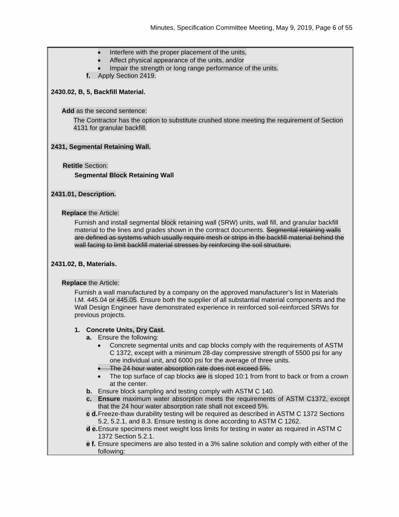
• Interfere with the proper placement of the units, • Affect physical appearance of the units, and/or • Impair the strength or long range performance of the units.
f. Apply Section 2419. 2430.02, B, 5, Backfill Material.
Add as the second sentence: The Contractor has the option to substitute crushed stone meeting the requirement of Section 4131 for granular backfill.
2431, Segmental Retaining Wall.
Retitle Section: Segmental Block Retaining Wall
2431.01, Description.
Replace the Article: Furnish and install segmental block retaining wall (SRW) units, wall fill, and granular backfill material to the lines and grades shown in the contract documents. Segmental retaining walls are defined as systems which usually require mesh or strips in the backfill material behind the wall facing to limit backfill material stresses by reinforcing the soil structure.
2431.02, B, Materials.
Replace the Article: Furnish a wall manufactured by a company on the approved manufacturer’s list in Materials I.M. 445.04 or 445.05. Ensure both the supplier of all substantial material components and the Wall Design Engineer have demonstrated experience in reinforced soil-reinforced SRWs for previous projects. 1. Concrete Units, Dry Cast.
a. Ensure the following: • Concrete segmental units and cap blocks comply with the requirements of ASTM
C 1372, except with a minimum 28-day compressive strength of 5500 psi for any one individual unit, and 6000 psi for the average of three units.
• The 24 hour water absorption rate does not exceed 5%. • The top surface of cap blocks are is sloped 10:1 from front to back or from a crown
at the center. b. Ensure block sampling and testing comply with ASTM C 140. c. Ensure maximum water absorption meets the requirements of ASTM C1372, except
that the 24 hour water absorption rate shall not exceed 5%. c d. Freeze-thaw durability testing will be required as described in ASTM C 1372 Sections
5.2, 5.2.1, and 8.3. Ensure testing is done according to ASTM C 1262. d e. Ensure specimens meet weight loss limits for testing in water as required in ASTM C
1372 Section 5.2.1. e f. Ensure specimens are also tested in a 3% saline solution and comply with either of the
following:
Minutes, Specification Committee Meeting, May 9, 2019, Page 7 of 55
• The weight loss of each of five test specimens at the conclusion of after 40 cycles does not exceed 1% of its initial weight; or
• The weight loss of four out of five specimens at the conclusion of after 50 cycles does not exceed 1.5% of its initial weight.
f g. Ensure testing is continued until one of the following occurs: • The weight loss each of five test specimens exceeds 2% of its initial weight, or • The weight loss of one of the five test specimens exceeds 2.5% of its initial weight,
or • The specimens have been tested for at least 100 cycles.
g h. Submit complete durability test reports for water and saline conditions, including the cycle number at which failure occurred, to the Engineer.
h i. Ensure all units are sound and free of cracks or other defects that would interfere with the proper placing of the unit or significantly impair the strength or permanence of the construction.
i j. Ensure SRW units dimensions do not differ by more than ± 1/16 1/8 inch. j k. Apply Section 2419.
2. Concrete Units, Wet Cast. a. Minimum 28 day compressive strength of 6000 psi for any one individual unit. b. Minimum compressive strength of 3500 psi achieved before blocks may be moved
and/or transferred to a storage site. c. Air content in the fresh concrete of 6.5%, -1%, +1.5 %. d. All aggregates, cement, mineral and liquid chemical admixtures from an approved
source and complying with the Standard Specifications. Minimum of Class 2 coarse aggregate durability.
d. Overall dimensions for width, height, and length do not differ by more than ± 1/8 inch from the specified minimum dimensions.
e. All units are sound and free of cracks or other defects that would: • Interfere with the proper placement of the units, • Affect physical appearance of the units, and/or • Impair the strength or long range performance of the units.
f. Apply Section 2419.
2 3. Leveling Pad. Use supplier/manufacturer recommended leveling pad materials. If granular material is recommended for the leveling pad, use backfill material meeting the requirements of Section 4132. If unreinforced concrete is recommended for the leveling pad, use Class C concrete meeting the requirements of the Materials I.M. 529 and Section 2403.
3 4. Unit Fill. If fill is required by the construction drawings for in-place concrete segmental block units, place porous backfill material meeting the requirements of Section 4131.
4 5. Subdrains. a. Ensure the subdrains are a minimum of 4 inches in diameter and meet the
requirements of Article 4143.01, B. b. Provide Standard Road Plan DR-305 Type A outlets and fit with rodent guards
(complying with Materials I.M. 443.01).
5 6. Backfill Material. Use granular backfill meeting the requirements of Section 4133 for fill soil material in the entire reinforced earth zone. The Contractor has the option to substitute crushed stone meeting the requirement of Section 4131 for granular backfill.
Minutes, Specification Committee Meeting, May 9, 2019, Page 8 of 55
6 7. Geogrid Reinforcement. Comply with the following: • Type, strength, and placement location determined by the Wall Design Engineer. • Design properties of the reinforcement determined according to the procedures
outlined in NCMA Section 3.5. • Detailed test data (including strength, creep, site damage, and pullout testing)
submitted to the Engineer for approval at least 30 days prior to construction. • Of a type recommended by the block supplier to be compatible with the facing units,
with a minimum long term design strength of 1500 pounds per foot. • Regular grid structure having an aperture geometry and rib and junction cross-sections
sufficient to permit significant mechanical interlock with the granular backfill material. • High continuity of tensile strength through all ribs and junctions of the grid structure. • High resistance to deformation under sustained long-term design load while in service,
and resistant to: 1) ultraviolet degradation; 2) damage under normal construction practices; and 3) all forms of biological or chemical degradation normally encountered in the granular backfill material.
7 8. Certifications.
a. Submit a notarized manufacturer’s certification to the Engineer at least 14 days prior to the preconstruction conference, stating that the SRW units meet the requirements of this specification.
b. Submit a notarized manufacturer’s certification signed and sealed by an officer of the manufacturer, prior to start of work, stating that the geogrid reinforcement meets the requirements of the SRW unit manufacturer and this specification.
2431.04, A, Segmental Retaining Wall.
Retitle the Article: Segmental Block Retaining Wall.
2431.05, A, Segmental Retaining Wall.
Retitle the Article: Segmental Block Retaining Wall.
Comments:
Member’s Requested Change: (Do not use ‘Track Changes’, or ‘Mark-Up’. Use Strikeout and Highlight.) 2430.01, Description.
Add as the last sentence: The type of concrete unit, dry cast or wet cast, will be specified elsewhere in the contract documents.
2430.02, B, 1, Concrete Units. Retitle article:
Concrete Units, Dry Cast.
2430.02, B, 2, Concrete Units, Wet Cast. Add as a new article:
a. Minimum 28 day compressive strength of 6000 psi for any one individual unit.
b. Minimum compressive strength of 3500 psi achieved before blocks are moved and/or

Minutes, Specification Committee Meeting, May 9, 2019, Page 9 of 55
transferred to a storage site.
c. Air content in the fresh concrete of 6.5%, minus 1%, plus 1.5 %.
d. Aggregates, cement, mineral and liquid chemical admixtures from an approved source and complying with the Iowa DOT Standard Specification requirements. Minimum of Class 2 coarse aggregate durability.
d. Overall dimensions for width, height and length do not differ by more than ± 1/8 inch from the specified minimum dimensions.
e. All units sound and free of cracks or other defects that would:
• Interfere with the proper placement of the units,
• Affect physical appearance of the units, and/or
• Impair the strength or long range performance of the units.
f. Apply Section 2419.
2430.02, B, 5, Backfill Material. Add as the second sentence:
The Contractor has the option to substitute crushed stone meeting the requirement of Section 4131 for granular backfill.
Renumber Articles 2430.02, B, 2 to 5 as Articles 2430.02, B, 3 to 6. 2431.01, Description.
Add as the last sentence: The type of concrete unit, dry cast or wet cast, will be specified elsewhere in the contract documents.
2431.02, B, Materials. Replace the first sentence:
Furnish a wall manufactured by a company on the approved manufacturer’s list in Materials I.M. 445.04 or 445.05.
2431.02, B, 1, Concrete Units. Retitle article:
Concrete Units, Dry Cast. Add new Article c:
Ensure maximum water absorption meets the requirements of ASTM C1372, except that the 24 hour water absorption rate shall not exceed 5%.
Renumber Articles 2431.02, B, 1, c to j as Articles 2431.02, B, 1, d to k.
2431.02, B, 2, Concrete Units, Wet Cast. Add as a new article:
a. Minimum 28 day compressive strength of 6000 psi for any one individual unit.
b. Minimum compressive strength of 3500 psi achieved before blocks may be moved and/or transferred to a storage site.

Minutes, Specification Committee Meeting, May 9, 2019, Page 10 of 55
c. Air content in the fresh concrete of 6.5%, minus 1%, plus 1.5 %.
d. All aggregates, cement, mineral and liquid chemical admixtures from an approved source and complying with the Iowa DOT Standard Specification requirements. Minimum of Class 2 coarse aggregate durability.
d. Overall dimensions for width, height, and length do not differ by more than ± 1/8 inch from the specified minimum dimensions.
e. All units sound and free of cracks or other defects that would:
• Interfere with the proper placement of the units,
• Affect physical appearance of the units, and/or
• Impair the strength or long range performance of the units.
f. Apply Section 2419.
2431.02, B, 6, Backfill Material. Add as the second sentence:
The Contractor has the option to substitute crushed stone meeting the requirement of Section 4131 for granular backfill.
Renumber Articles 2431.02, B, 2 to 7 as 2431.02, B, 3 to 8.
Reason for Revision: To add an option of wet cast block Materials to Sections 2430 and 2431. Current Specifications allow only dry cast block Materials according to DOT Materials I.M. 445.04 (CONCRETE SEGMENTAL & MODULAR BLOCKS, DRY CAST).
Wet cast block has been specified in local projects using Special Provisions SP-152022 and SP-156096 for Modular Block Retaining Wall (Heavy). These have been proprietary large units for gravity walls. Wet cast block is produced with air entrainment, with comparable strength and durability to dry cast block.
DOT Materials I.M. 445.05 (CONCRETE SEGMENTAL BLOCKS, WET CAST) is used for approval of wet cast block. DOT Materials is rewriting I.M. 445.04 and 445.05 to remove material specification text, which is proposed to be moved to Specification Sections 2430 and 2431. I.M. changes have been coordinated with the proposed revisions to Sections 2430 and 2431.
The revision will allow the option of dry cast or wet cast block under Standard Specifications.
An alternative Backfill Material is also proposed to allow use of crushed stone Porous Backfill per Section 4131, instead of Granular Backfill per Section 4133. This allows the contractor to use the same material as specified for Unit Fill of voids in concrete block units.
New Bid Item Required (X one) Yes No X
Bid Item Modification Required (X one) Yes No X
Bid Item Obsoletion Required (X one) Yes No X
Comments:
County or City Comments: SUDAS Director Paul Wiegand has been involved in discussions and has reviewed the proposed changes.
Industry Comments:

Minutes, Specification Committee Meeting, May 9, 2019, Page 11 of 55
Form 510130 (08-15)
SPECIFICATION REVISION SUBMITTAL FORM Submitted by: Eric Johnsen / Tom Reis Office: Specifications Item 3
Submittal Date: 4/22/2019 Proposed Effective Date: 10/15/2019
Article No.: 2435.03, A, 10 Title: Casting
Other:
Specification Committee Action: Approved with changes.
Deferred: Not Approved: Approved Date: 5/9/2019 Effective Date: 10/15/2019
Specification Committee Approved Text: 2435.03, A, 10, Casting.
Replace the Article: 1. Install the type of casting specified in the contract documents and adjust to proper grade. 2. Where a manhole or intake is to be in a paved area, adjust the casting to match the slope
of the finished surface. When specified in the contract documents, attach a casting frame to the structure with four anchor bolts.
3. Three-piece Castings.
a. Attach the frame to the structure with four anchor bolts. b. Set initial position of movable portion of the casting in the center of the adjustment
range. c. Remove height-adjustment bolts or mechanism after the paving is completed.
Comments: SUDAS requested an additional requirement for three-piece castings be added regarding the initial position of the adjustable casting.
Specification Section Recommended Text: 2435.03, A, 10, Casting.
Replace the Article: 1. Install the type of casting specified in the contract documents and adjust to proper grade.
2. Where a manhole or intake is to be in a paved area, adjust the casting to match the slope
of the finished surface. When specified in the contract documents, attach a casting frame to the structure with four anchor bolts.
3. Three-piece Castings. a. Attach the frame to the structure with four anchor bolts. b. Remove height-adjustment bolts or mechanism after the paving is completed.
Comments: Road Standards will be updated to show the three piece casting.
Member’s Requested Change: (Do not use ‘Track Changes’, or ‘Mark-Up’. Use Strikeout and Highlight.)
Minutes, Specification Committee Meeting, May 9, 2019, Page 12 of 55
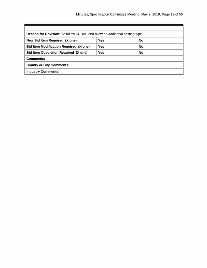
Reason for Revision: To follow SUDAS and allow an additional casting type.
New Bid Item Required (X one) Yes No
Bid Item Modification Required (X one) Yes No
Bid Item Obsoletion Required (X one) Yes No
Comments:
County or City Comments:
Industry Comments:
Minutes, Specification Committee Meeting, May 9, 2019, Page 13 of 55
Form 510130 (08-15)
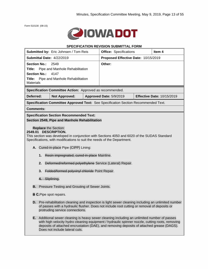
SPECIFICATION REVISION SUBMITTAL FORM Submitted by: Eric Johnsen / Tom Reis Office: Specifications Item 4
Submittal Date: 4/22/2019 Proposed Effective Date: 10/15/2019
Section No.: 2549 Title: Pipe and Manhole Rehabilitation Section No.: 4147 Title: Pipe and Manhole Rehabilitation Materials
Other:
Specification Committee Action: Approved as recommended.
Deferred: Not Approved: Approved Date: 5/9/2019 Effective Date: 10/15/2019
Specification Committee Approved Text: See Specification Section Recommended Text.
Comments:
Specification Section Recommended Text: Section 2549, Pipe and Manhole Rehabilitation
Replace the Section: 2549.01 DESCRIPTION. This section was developed in conjunction with Sections 4050 and 6020 of the SUDAS Standard Specifications, with modifications to suit the needs of the Department.
A. Cured-in-place Pipe (CIPP) Lining:
1. Resin impregnated, cured-in-place Mainline. 2. Deformed/reformed polyethylene Service (Lateral) Repair. 3. Folded/formed polyvinyl chloride Point Repair. 4. Sliplining.
B. Pressure Testing and Grouting of Sewer Joints. B C.Pipe spot repairs. D. Pre-rehabilitation cleaning and inspection is light sewer cleaning including an unlimited number
of passes with a hydraulic flusher. Does not include root cutting or removal of deposits or protruding service connections.
E. Additional sewer cleaning is heavy sewer cleaning including an unlimited number of passes
with high velocity hydro cleaning equipment / hydraulic spinner nozzle, cutting roots, removing deposits of attached encrustation (DAE), and removing deposits of attached grease (DAGS). Does not include lateral cuts.
Minutes, Specification Committee Meeting, May 9, 2019, Page 14 of 55
C F.Rehabilitate existing manholes to waterproof and to prevent inflow and infiltration, to prevent corrosion, or to reestablish the structural integrity of the manhole. Includes construction of structural liners, protective liners, and infiltration barriers.
2549.02 MATERIALS.
A. Pipe Rehabilitation. 1. Apply Article 4147.01. 2. Submittals.
a. CIPP Rehabilitation. 1) Thickness Design: Submit design calculations for CIPP wall thickness based
upon ASTM F 1216, prepared and signed by a licensed Professional Engineer in the State of Iowa.
2) Resin: Certificate of compliance with ASTM F 1216 or D 5813. 3) Tube: Certificate of compliance with ASTM F 1216 or F 2019. If glass fiber
reinforcement is used, CIPP strain corrosion testing according to ASTM D 3681. 4) Wet Out and Curing: Complete description of the manufacturer’s recommended
wet out procedure and curing method for the type of lining proposed. 5) Safety Procedures: When required in the contract documents, submit
documentation of National Institute of Occupational Safety and Health (NIOSH) testing, health hazard evaluation, and recommended safety procedures for CIPP workers and public.
b. Grouting Sewer Joints and Service Connections. 1) Grout: Description of chemical grout materials to be used. 2) Additives: Description of additives to be used including strengthening agents,
shrinkage reducers, dye, viscosity modifiers, gel time modifier, freeze/thaw inhibiter, or others.
3) Root Inhibitor: Description of chemical root deterrent. 4) Procedures: Manufacturer’s published recommendations for storing, mixing,
testing, and handling chemical grouts. c. Installer Information: When requested by the Contracting Authority, submit the
following prior to the preconstruction meeting. 1) Installer name. 2) Completed project list for last 5 years including for each project and year
completed, client name/address/contact person/phone number, footages installed by pipe diameter, and number of lateral reinstatements.
3) Detailed installation procedures, including estimated times for each task, lateral reinstatement methods, number of required excavations, and other items unique to each product.
4) Video of installation process, if available. 5) Evidence of properly trained personnel. 6) Related ASTM standards or any nationally recognized standards for product
installation. 7) Available equipment list. 8) Detailed procedures for repairing the product in the event of future damage or
failure and for tapping future service connections, including and required specialized equipment or training.
9) Videos of two rehabilitated sewer sections showing before and after conditions. d. Additional information may be required. The submittal of prequalification information in
no way implies that the product, manufacturer, or installer will be deemed to be qualified. The Contracting Authority, in its sole discretion, will determine whether a product, manufacturer, or installer does or does not qualify as an approved equal.

Minutes, Specification Committee Meeting, May 9, 2019, Page 15 of 55
2 3. The Engineer may allow substitutions. Provide as a minimum the following information for evaluation: a. Product Information.
1) Product name. 2) Year product first available in the United States. 3) Total footage or number of line segments installed in the United States. 4) Results of all available product testing, including but not limited to leakage,
physical properties, pipe stiffness, chemical resistance, strain-corrosion, external loading, flow characteristics, infiltration/inflow reductions, structural capacity, and external hydrostatic loading capacity.
5) Samples of before and after product. 6) Design method. 7) Typical lining thickness for pipe sizes included in the project.
b. Manufacturer Information. 1) Manufacturer name. 2) Years of experience manufacturing the product. 3) Country of manufacture of all product components. 4) Quality control procedures for product manufacture, including inspection
requirements, testing procedures, and allowable tolerance levels. 5) Related ASTM standards, or other nationally recognized standards for product
manufacturing. c. Installer Information.
1) Installer name. 2) Completed project list for last five years including for each project and year
completed, client name/address/contact person/phone number, footages installed by pipe diameter, and number of lateral reinstatements.
3) Detailed installation procedures, including estimated times for each task, lateral reinstatement methods, number of required excavations, and other items unique to each product.
4) Video of installation process, if available. 5) Evidence of properly trained personnel. 6) Related ASTM standards or any nationally recognized standards for product
installation. 7) Available equipment list. 8) Detailed procedures for repairing the product in the event of future damage or
failure and for tapping future service connections, including required specialized equipment or training.
9) Videos of two rehabilitated sewer sections showing before and after conditions. 10) Additional information may be required. The submittal of prequalification
information in no way implies that the product, manufacturer, or installer will be deemed to be qualified. The Contracting Authority, in its sole discretion, will determine whether a product, manufacturer, or installer does or does not qualify as an approved equal.
B. Manhole Rehabilitation.
Apply Article 4147.02 2549.03 CONSTRUCTION.
A. Pipe Rehabilitation.
1. Public Relations Program. Establish a Public Information and Notification Program for contacting each home or business connected to the affected sanitary sewer, informing them of the work to be done and when the sewer will be off line. The following specific steps are part of the Public Information and Notification Program:
Minutes, Specification Committee Meeting, May 9, 2019, Page 16 of 55
a. Provide written notice to be delivered to each affected home or business describing work, schedule, how the work affects them, and a local telephone number of the Contractor they can call to discuss the project or their problems.
b. Personally contact each home or business on the day lateral verifications using closed circuit video inspection are to be performed. The homeowner or business will be asked to run water down their drain to verify each lateral. If the homeowner is unavailable, attempt other arrangements (cleanouts) to drain water through the lateral to verify each connection.
c. Provide written notice and personally contact the home or business the day prior to beginning inversion of the section of sewer to which they are connected.
d. Personally contact all homes or businesses that cannot be reconnected within the time stated in the written notice.
e. Furnish and service portable toilets for use by the home or business occupants if so required by any affected served business or homeowner.
2. Special Requirements.
a. Prior to start of work, notify all affected parties 24 hours in advance as to the length of time their service will be blocked.
b. Notify the Engineer’s Water Works Department to use meter and pay for water, if required.
c. Unless specified otherwise, the Contracting Authority will provide water at no cost for cleaning and installation of cured-in-place pipe from a nearby hydrant through a separate valve mounted on the hydrant. Utilize an approved double check backflow assembly or open gap.
3. Examination.
a. Cleaning. 1) Clean and remove soil, grit, debris, and obstructions prior to video inspection or
insertion of lining pipe, or both. 2) Do not flush debris to downstream sections. 3) Deposit removed material at an approved site.
b. Video Inspection. 1) Furnish the Engineer with a recording of sewers: 1) before the lining process and
while the flow is being bypassed; and 2) after lining process and service reconnections have been completed.
2) Provide an on screen numerical display of camera location, indexed from the starting manhole, in feet (meters).
c. Service and Obstruction Location. 1) Coordinate and cooperate with the Engineer for service and obstruction location. 2) Locate the active sewer services by one of following:
a) Use video inspection to observe service locations, breaks, obstructions, and structural failures.
b) Insert a sounding device through the service, noting its location on the ground surface.
c) Dye testing.
4. Bypassing Sewage. a. Submit a bypassing plan to the Engineer for review. b. Plug the line at a point upstream of pipe to be rehabilitated if bypassing is required. c. Pump flow to a downstream point or adjacent system as directed by the Engineer.
1) Provide pump and bypass lines of adequate capacity to handle all flows. 2) Provide adequate reserve pumps on site for emergency use and for storm flows.
5. Obstructions. a. Remove all obstructions.
Minutes, Specification Committee Meeting, May 9, 2019, Page 17 of 55
b. If an obstruction is encountered that cannot be removed by equipment operating within the pipe, excavate and remove the obstruction upon approval of the Engineer.
c. Place backfill material, compact, and restore the surface according to the contract documents.
6. Temporary Sewer Service.
If full normal sewer service is not re-established within the times stated, provide temporary facilities or hotel accommodations for affected residents and businesses.
7. Sliplining. a. Excavation.
1) For sliplining insertions, excavate at or near one structure and work from the existing manhole at the other end of the section to be pulled.
2) Insertion Pit. a) For sliplining with segmented pipe (one pipe section at a time), construct the
insertion pit as required to accommodate the length of individual pipe sections. b) For sliplining with pipe that is to be welded together above ground and pulled
into sewer, dig a pit length 12 times the inside pipe diameter and slope the pit end back to the ground surface at 2.5 (horizontal) to 1.0 (vertical).
b. Test Head. 1) Pull the pulling head with one short section of slipling pipe through the sewer
before inserting the liner to test for taps or obstructions protruding too far into the sewer.
2) Attach cables to both ends of the test head to allow for removal if an obstruction is encountered.
c. Installation. Push segmented pipe into the host pipe according to the manufacturer’s recommendations, or pull in a continuously welded pipe according to ASTM F 585.
d. Service Reconnection. 1) Allow the sliplining pipe to recover according to the manufacturer’s
recommendations. 2) Do not leave the sanitary service unconnected for more than 24 hours. 3) Complete reconnections involving excavation of service lines according to the local
plumbing codes. 4) Reconnect excavated service connections according to the local plumbing code,
except that the annular space between the host pipe and the sliplining pipe is to be filled with grout.
e. Grouting. 1) Before trimming the ends of the pipe and sealing, allow for the pipe to recover its
original length according to the manufacturer’s recommendations. Recovery time is at least equal to the time required to pull the pipe into place.
2) Fill the space between the sliplining pipe and the host pipe with CLSM complying with Article 2552.02, E, 3, or other material approved by the Engineer. Pump filler in from the lower end of the sliplining pipe.
8. Resin Impregnated Cured-In-Place Pipe Lining.
a. Install according to the manufacturer’s recommendations for this lining process and ASTM F 1216 unless noted otherwise.
b. Use a resin impregnated tube, hydraulically inverted in place with an approved lubricant, and cured in place according to ASTM F 1216, Section 7.
c. Make the tube continuous between manholes. The tube may span several manhole reaches as allowed by the equipment, properties of the CIPP, and the size and condition of the sewer.
d. Ensure the tube is free of uncured spots, lifts (spots cured away from the sewer), and delaminations. Remove and replace deficient sections.
e. Service Reconnections.

Minutes, Specification Committee Meeting, May 9, 2019, Page 18 of 55
1) Do not leave sanitary service unconnected for more than 24 hours. 2) Complete reconnections involving excavation of service lines according to the local
plumbing code.
9. Deformed/Reformed High Density Polyethylene Pipe or Folded/Formed Polyvinyl Chloride Pipe Lining Installation. Install according to the manufacturer’s recommendations for particular lining material and process, unless specified otherwise. a. Lining Installation.
1) Designate location where insertion is to begin, subject to the Engineer's approval. 2) Transport lining to the site in one continuous length on spools compatible with
manufacturer’s designated process. 3) Heat lining material at the job site as necessary for insertion. Pull lining into the
sewer with appropriate pulling heads, cables, and heat distribution equipment. 4) Ensure lining is continuous between manholes as allowed by the tensile properties
of lining and the size and condition of the sewer. 5) Connect fully inserted lining to the heat source distribution equipment. 6) Round and expand by uniformly distributed heat, steam, and pressure and by
mechanical devices. 7) After lining has been expanded to a tight fit, cool gradually under pressure until the
process is complete. 8) Provide a continuous pipe lining, without joints, over the entire length of pipe. 9) Ensure the lining is free of all material defects, pits, pinholes, cracks, crazing,
folds, or unrounded sections. 10) Repair all defects at no additional cost to the Contracting Authority.
b. Service Reconnections. 1) Do not leave sanitary service unconnected for more than 24 hours. 2) Complete reconnections involving excavation of service lines according to the local
plumbing code.
3. Sewer Cleaning and Inspection for Rehabilitation. a. General.
1) Provide equipment specifically designed and constructed for sewer cleaning and inspection.
2) Use sewer cleaning equipment manufacturer’s recommended size tools for various pipe sizes.
3) Utilize equipment recommended by the manufacturer to protect the manhole and pipe during cleaning and inspection operations.
4) Perform all cleaning and removal operations under CCTV observation to monitor the progress of the work and to monitor the sewer line for damage. Continue until the condition of the host pipe meets the requirements of the liner manufacturer.
5) Flush all debris to downstream manhole. Screen, collect, and remove debris from sewer.
6) Dispose of all sanitary sewer debris and material at a location directed by the Contracting Authority. If specified in the contract documents, pay for all disposal fees.
b. Pre-Cleaning Inspection. 1) Complete CCTV inspection of sewer prior to initiating cleaning. 2) Inspect each pipe segment between manholes or access points in a single,
continuous run where possible. 3) If line is impassable due to debris or obstructions, reverse setup and inspect from
opposite manhole or access point. c. Pre-Rehabilitation Sewer Pipe Cleaning.
1) Perform light cleaning with hydraulic flusher or high velocity cleaning equipment to remove loose debris.
2) Complete up to three passes in an attempt to remove all debris from line.
Minutes, Specification Committee Meeting, May 9, 2019, Page 19 of 55
3) If the pre-rehabilitation light cleaning fails to leave the sewer line in a condition ready for lining, contact Engineer for authorization to proceed with additional sewer cleaning.
d. Additional Sewer Cleaning. 1) Notifying Engineer prior to performing heavy cleaning as required to remove
obstructions, grease, rock, sticks, deposits settled (DS), deposits attached grease (DAGS), deposits attached encrustation (DAE), and roots, so the sewer is ready for lining. This item does not include cutting/grinding protruding service lines.
2) Utilize rotating nozzles, saws or cutters, or high velocity hydro-cleaning equipment. 3) Notify Engineer prior to use of mechanical/hydraulic spinner nozzle, chain flail, or
other devices that may damage pipe or service connections. 4) If deposits and obstructions cannot be removed by tools normally used in the
sewer cleaning industry, notify Engineer immediately. 5) Maintain a log of time spent performing additional pipe cleaning on each line
segment. e. Remove Protruding Service Connection.
1) Grind or cut services that protrude more than 1/2 inch into the sewer main. 2) Utilize a remote grinding/cutting device specifically designed to remove concrete,
vitrified clay, PVC, and other types of pipe materials. 3) Notify Engineer if ductile iron, steel, cast iron, or other non-typical service materials
are encountered to review the ability and risks of removing the protruding services. 4) Grind or cut protruding service flush to the main sewer pipe without scouring or
damaging the main sewer or service connection. 5) Notify the Engineer immediately if the sewer main or service pipe are not
structurally sound. f. Post-Cleaning CCTV Inspection.
1) Complete CCTV inspection of sewer upon completion of all sewer cleaning, obstruction removal, and protruding service removal activities.
2) Inspect each pipe segment between manholes or access points in a single, continuous run.
3) Inspect all service connections at right angles utilizing pan and tilt capabilities of the camera.
4) Identify active and inactive service connections by the following: a) Observe each service connection and identify active connections by active
sewage flow or evidence of recent sewage flow. b) If the status of the connection is inconclusive, run water down adjacent
services to verify the location of each service. c) Dye test connections if necessary to verify active status. d) b. Accurately measure and log the location and clockwise position of all active
service connections. g. Groundwater.
If significant groundwater infiltration is present, which could result in resin loss, resin contamination, reduction in CIPP thickness, or inadequate curing, notify the Engineer prior to installing CIPP liner.
h. Inspection Reporting. 1) Provide a copy of the pre-cleaning and post-cleaning video inspections. Include
on-screen continuous footage, pipe diameter, direction of viewing, manhole number, and street location reference in the recording. Affix labels to the recording media to include the name of the project, the date, and the location of the inspection.
2) Provide a written report of the inspections. Include true to scale drawings of all sewer defects and observation locations. Reference the time stamp on each line item entry on the written report.
4. Bypassing Sewage.
a. Submit a bypassing plan to the Engineer for review.

Minutes, Specification Committee Meeting, May 9, 2019, Page 20 of 55
b. When sewer line flows exceed the values in Table 2549.03-1, or the depth recommended by the manufacturer of the sewer rehabilitation practice being implemented, reduce flows to acceptable levels. 1) Plug the line at a point upstream of pipe to be rehabilitated if bypassing is required. 2) Pump flow to a downstream point or adjacent system as directed by the Engineer.
a) Provide pump and bypass lines of adequate capacity to handle all flows. b) Provide adequate reserve pumps on-site for emergency use and for storm
flows. c. Rehabilitation and inspection work may be completed without bypassing in certain
situations including low flow conditions, adequate upstream storage, use of a flow-through packer, or other situations approved by the Engineer. If proposed work will be completed without bypassing, have equipment and plan of action available to implement bypass pumping in the event the work is delayed or sewage levels in the upstream line are in danger of causing backups.
Table 2549.03-1: Maximum Depth of Flow During Inspection, Testing, and Rehabilitation
Main Diameter CCTV Inspection Joint Testing/Sealing 6” to 10” 20% of pipe diameter 25% of pipe diameter 12” to 24” 25% of pipe diameter 30% of pipe diameter 27” and up 30% of pipe diameter 35% of pipe diameter
5. CIPP Main Lining.
a. General. 1) Clean, prepare, and inspect the repair point according to Article 2549.03, A, 3. 2) Install liner according to the manufacturer’s published recommendations,
ASTM F 1216, and ASTM F 2019. b. Resin Impregnation.
1) Vacuum impregnate tube with resin (wet-out) at manufacturer’s plant under quality controlled conditions or on-site in mobile wet-out unit.
2) Fill all voids in the tube material, adding 5% to 10% excess resin to allow for migration of resin into the voids and cracks.
c. Insertion. 1) General.
a) Perform pre-lining video inspection immediately prior to insertion of the wet-out tube.
b) Insert the wet-out tube through an existing manhole or approved access. c) Ensure the tube is continuous between manholes with no joints. A single
tube may span several manhole reaches as allowed by the equipment, properties of the CIPP, and time limits imposed by sewage flows to the host pipe.
d) Insertion of CIPP indicates acceptance of the host pipe conditions and the suitability of the liner inserted into the host pipe. Repair any failure of CIPP liner due to inadequate cleaning, groundwater infiltration, or defects in the liner system at no additional cost to the Contracting Authority.
2) Inverted Heat-Cured Liner. a) Prior to installation of the liner, place a temperature sensor on the bottom
of the host pipe to monitor the temperature of the outside of the liner during the curing process. Place sensor at the termination point or location most distant from the heat source.
b) Insert the wet-out tube into the inversion device or standpipe with the impermeable plastic liner on the outside of the tube.
c) Turn back the end of the liner to form a cuff and secure the cuff to the inversion device or standpipe.
Minutes, Specification Committee Meeting, May 9, 2019, Page 21 of 55
d) Apply air pressure or hydrostatic head as required to invert the tube into the host pipe with the impermeable liner on the inside of the pipe.
e) Apply lubricant directly to the tube or pour lubricant into the standpipe during the inversion process to reduce friction.
f) Maintain and adjust pressure as necessary to invert the tube from the point of insertion to the point of termination and to hold the tube tight against the wall, producing dimples at service connections.
3) Pull-In UV Light Cured Liner. a) If CIPP manufacturer recommends the use of a sliding foil for the existing
pipe conditions, provide sliding foil which covers the lower third to lower half of the pipe circumference. Pull sliding foil into place.
b) Fold the wet-out liner in half and pull into place through an existing manhole. Monitor pulling speed and tension to avoid exceeding the manufacturer’s recommendations.
c) Pull 1 to 2 feet of excess liner into the termination manhole. d) If the product is sensitive to elongation, measure the overall elongation of
the tube after pull-in. Ensure the elongation of the tube is less than 2% of the overall length of the segment specified by the manufacturer.
e) Expand the resin-impregnated tube as necessary to hold the tube tight against the wall, producing dimples at service connections.
f) Perform CCTV inspection of the inflated liner prior to initiating cure. Confirm alignment and fit prior to initiating cure. Make corrections as necessary to provide a finished liner free of wrinkles and defects.
d. D. Curing: 1) Heat Cured.
a) Maintain consistent pressure, as recommended by the liner manufacturer, until curing is complete. Increase pressures to compensate for external ground water, if present.
b) Cure liner using circulating heated water or steam. Ensure the temperature is sufficient to affect a cure in all sections of the pipe.
c) Monitor and log the temperature from the sensor placed between the impregnated tube and the host pipe.
d) Initial cure will occur during heat up and is achieved when exposed portions of the new pipe appear to be hard and sound and the temperature sensor indicates the liner has reached the temperature necessary to effect a cure in the resin.
e) After initial cure is reached, raise the temperature to post-cure temperatures and hold for a period of time as recommended by the resin manufacturer.
f) Cool the new pipe to a temperature of 100°F for water cure and 113°F for steam cure before relieving the internal pressure within the section.
2) UV Light Cured. 1) Automatically record the time, rate of travel of the ultraviolet assembly,
pressures, and amount of lamps in operation for each CIPP segment as documentation of correct curing of the fabric tube.
2) Maintain consistent pressure, as recommended by the liner manufacturer, until curing is complete.
3) Draw the multi-lamp ultraviolet curing assembly through the pipe at a consistent, predetermined, speed that allows for cross-linking/polymerization of the CIPP resin.
4) Adjust air pressure during curing as necessary to hold liner tight to the wall. Maintain pressure by adjustment of the outlet valve.
5) Remove the temporary internal calibration hose installed by the manufacturer after curing is complete.
e. CIPP End Seal Installation. 1) Hydrophilic Gasket Sleeve.
Minutes, Specification Committee Meeting, May 9, 2019, Page 22 of 55
Install sleeve according to ASTM F 3240, sleeve manufacturer’s published recommendations, and the following: a) Do not install sleeve in host pipe more than 24 hours prior to CIPP lining. b) Clean the first 6 inches of the main pipe to remove debris and visible
grease deposits. c) Install metal retaining clip at the leading edge of the sleeve. The metal clip
may be held in place with adhesive tape if desired. d) Install the sleeve in the main pipe so the leading edge is no more than 6
inches inside the end of the main pipe as measured from the manhole wall.
e) If the main pipe has a diameter of 18 inches or larger, utilize anchor screws to hold the sleeve in place.
2) Expansion Band System. Install system according to manufacturer’s published recommendations and the following: a) After installation of the CIPP liner, trim the end of the liner squarely a
distance of 2 to 6 inches from the inside face of the manhole. b) Clean the exposed face of the main pipe to remove debris and loose resin. c) Slide the rubber gasket into the pipe, centering it over the end of the liner.
Ensure one expansion band will seat against the liner and the other will seat against the main pipe.
d) Expand the expansion bands using a hydraulic expansion tool approved by the band manufacturer.
f. Service Reinstatement. 1) Do not leave sanitary service blocked for more than 24 hours. 2) Reinstate active service lines from within the main with a CCTV camera and
remote cutting tool. Do not reinstate inactive service connections. 3) Machine the opening to full size of the service connection opening area.
Ensure the bottom of the liner opening and service line are flush. 4) Ensure the opening does not have pipe fragments or CIPP fragments that may
obstruct flow or snag debris. 5) In the event that service reinstatement results in a liner opening greater than
100% of the service connection opening, or damage to the service connection occurs, install a CIPP service repair to cover the over-cut service connection at no additional cost to the Contracting Authority.
6) If service connection cannot be reinstated remotely and requires excavation complete according to the local plumbing code at no additional cost to Contracting Authority.
g. Inspection. 1) Perform CCTV video inspection of completed CIPP lining, including
observance of reinstated service connections. Provide copy of video inspection to Jurisdiction.
2) Ensure the tube is free of dry spots, lifts (spots cured away from the sewer), and delaminations. Remove and replace deficient sections.
3) If the CIPP does not fit tight against the original pipe at its termination point, seal the space between the pipes by filling with a resin mixture or hydrophilic seal compatible with the CIPP.
6. CIPP Point Repair.
a. Preparation: Clean, prepare, and inspect the repair point according to Section 4050, 3.01.
b. Bypass Pumping: Develop a plan for flow diversion or stoppage. Review with Engineer prior to initiating repair.
c. Installation. 1) Bypass mainline flow according to the submitted bypass plan.

Minutes, Specification Committee Meeting, May 9, 2019, Page 23 of 55
2) Install CIPP point repair according to system manufacturer’s published recommendations.
3) Wet-out the liner with the entire volume of resin recommended by the manufacturer.
4) Load the wet-out liner onto the packer and secure in place. Ensure the ends of the packer extend beyond the ends of the liner.
5) Pull the packer into position within the pipe. Verify position with CCTV observation.
6) Apply air pressure to the packer to expand the CIPP point repair liner against the host pipe.
7) Maintain consistent pressure for the duration of the curing period. d. Inspection.
1) Perform CCTV video inspection of completed CIPP point repair. Provide copy of video inspection to Jurisdiction.
2) Ensure the tube is free of foreign inclusions, dry spots, pinholes, wrinkles greater than 2% of the pipe diameter, and delamination. Remove and replace deficient sections.
7. CIPP Service Repair.
a. Preparation. 1) Prior to installation of the system, clean and prepare the interior of the host
and service pipe in according to the manufacturer’s written instructions. 2) Remove all debris and obstructions. 3) Perform a post cleaning CCTV inspection in preparation for installation of the
lining system. 4) If any obstructions, joint misalignments, broken or collapsed pipe, or other
conditions are identified that will prohibit proper installation of the system, notify the Engineer immediately.
b. Installation. 1) Install CIPP service repair according to system manufacturer’s published
recommendations and to the length specified in the contract documents. 2) Bypass main line flow according to the submitted bypass plan. Coordinate
installation with service owner to prevent service line flows. 3) Wet-out the entire liner, including lateral and mainline portions, using vacuum
impregnation. 4) Load the lining system inside or on a pressure apparatus and move into
position in the mainline pipe at the service connection. 5) Align and verify the position of liner and service line via CCTV prior to initiating
installation. 6) Apply air pressure to invert or expand the resin impregnated CIPP into the
lateral pipe and push the main-line portion of the system against the main pipe. Maintain pressure until the curing process is complete.
7) Apply heat or UV light as required by the manufacturer to property cure the liner.
8) If liner is heat cured, follow manufacturer’s recommendations for cool-down before relieving pressure.
9) If liner is ambient cured, maintain pressure according to the manufacturer’s recommendations before relieving pressure.
10) Remove frayed ends of the system. c. Inspection and Documentation.
1) Provide Engineer with video documentation of pre-installation conditions and post-installation conditions showing the repair.
2) Ensure the finished CIPP service repair is free of any leakage and visual defects including foreign inclusions, dry spots, lifts, pinholes, major wrinkles, and delamination. Repair any defects that could affect the structural integrity of the system or allow leaks.

Minutes, Specification Committee Meeting, May 9, 2019, Page 24 of 55
3) Maintain a written log of installation conditions according to system manufacturer’s recommendations. At a minimum, include time of wet out, time and location of insertion, time of inflation, bladder pressure requirements, required cure time, actual cure time, and cool down duration.
4) Submit documentation of results for CIPP liner material to Engineer.
8. Pressure Testing and Grouting of Sewer Joints. a. General.
1) Clean, prepare, and inspect the repair point according to Article 2549.03, A, 3. 2) Complete sewer joint and service connection testing and grouting according to
the grout supplier and equipment manufacturer’s published recommendations, ASTM F 2304, and ASTM F 2454.
b. Equipment. 1) Joint Testing Device: Provide a joint testing device (packer), with means for
introducing air under pressure into the void area created by the expanded ends of the packer against the host pipe and a means of continuously measuring, viewing, and recording the static pressure of the test medium and grout within the void area only. Provide packer constructed in a manner to allow a limited amount of sewage to flow through at all times.
2) Service Connection Testing Device: Provide a service connection testing device with inflatable mainline end elements and a service line grouting plug that creates a void area extending beyond the main connection. Use a service line grouting plug sized to match the diameter of the service being grouted with an effective sealing length of at least 18 inches, unless otherwise specified in the contract documents.
3) Pumping Equipment. a) Provide positive displacement metering grout pump and hose delivery
system capable of supplying a mixed volume of grout at a minimum of 3 gallons per minute and 30 gallons of uninterrupted flow within 10 minutes.
b) Ensure pump system has sufficient discharge pressure (in excess of system pressure losses and groundwater) to deliver grout volume to fill void space within the gel set time of the chemical grout.
4) Grout Tanks: When using non-soluble additives, ensure grout tanks have mechanical mixing devices to keep additives in suspension.
5) Measuring Equipment: Provide means of measuring and recording the volume of mixed grout pumped for each grouted joint or service connection.
c. Control Tests. 1) Prior to beginning testing and grouting, perform a demonstration test in an
above ground 8 inch nominal diameter test cylinder suitable to contain the full length of the packer and sustain the void test pressure. For service line testing, provide an 8 inch test cylinder with 6 inch service tee to receive the lateral bladder.
2) Equip the test cylinder with a pressure gauge to monitor internal pressure and a release valve to exercise a controlled release of pressurized air from the void area to test the packer under both sound and leaking conditions. a) With the void release valve closed, inflate the packer and air test the void
at 7 to 10 psi. Ensure the observed void pressure at the test cylinder pressure gauge is within + 1/2 psi of the test monitoring equipment.
b) Crack open the release valve to simulate a small leak. Ensure the pressure drop of the cylinder gauge is within + 1/2 psi of the test monitoring equipment.
3) After entering each pipeline segment, but prior to commencement of joint testing, position the packer on a section of sound and clean sewer between two consecutive pipe joints and perform a pressure test. Pressurize packer to between 7 and 10 psi and hold for a period of 15 seconds with a pressure drop

Minutes, Specification Committee Meeting, May 9, 2019, Page 25 of 55
of less than 1.0 psi. Deflate packer and ensure that void pressure monitoring equipment drops + 1/2 psi of initial reading.
4) If any of the control tests are unsuccessful, clean equipment of excess grout or make necessary repairs and retest.
d. Sewer Main Joint Pressure Testing. 1) Test joints at a target pressure equal to 1/2 psi per vertical foot of pipe depth
plus 2 psi (not exceeding 10 psi). 2) Position the packer within the pipe so the packer straddles the pipe joint to be
tested. Verify location via CCTV monitoring. 3) Expand the packer ends to isolate the joint from the remainder of the pipe and
to create a void area between the pipe joint and testing device. 4) Pump air into void space until the pressure reaches the required test pressure. 5) Stop the flow of air into the void space and observe the void pressure for 15
seconds. 6) If the pressure is maintained with a drop of less than 1 psi, the joint will be
considered as having passed the test. 7) If the pressure drops more than 1 psi during the test period, the joint will be
considered as having failed and sealing will be required. 8) Deflate packer and verify the void pressure monitor drops to within + 1/2 psi of
0 psi. Clean equipment if pressure fails to return to 0 psi. e. Service Line Pressure Testing.
1) Test service lines at a target pressure equal to 1/2 psi per vertical foot of pipe depth plus 2 psi (not exceeding 10 psi).
2) Position the testing device within the line segment to straddle the service connection. Verify location via CCTV.
3) Align the service bladder with the service connection. 4) Apply air pressure to invert or inflate the bladder from the mainline assembly
into the service pipe. 5) Expand the packer ends to isolate the section of the service connection to be
tested. 6) Introduce air into the void area until a pressure equal to or up to 10% greater
than the required test pressure is observed. 7) Stop the flow of air into the void space and observe the void pressure for 15
seconds. 8) If the pressure is maintained, with a pressure drop of less than 2 psi, the
connection will be considered as having passed the test. 9) If the pressure drops more than 2 psi during the test period, the connection will
be considered as having failed and sealing will be required. 10) Deflate packer and bladder and verify the void pressure monitor drops to within
+ 1/2 psi of 0 psi. Clean equipment if pressure fails to return to 0 psi. f. Sewer Main Joint Sealing by Injection Grouting.
Perform joint sealing according to ASTM F 2304, equipment manufacturer, grout supplier, and the following: 1) Position packer over the faulty joint and expand packer ends, isolating the joint
with a tight seal. 2) Pump two-part chemical sealant material into the ratio specified by the grout
supplier. 3) Continue to pump grout, in stages if necessary, until “refusal” is achieved.
a) Refusal indicates the grout has flowed throughout the void, into the surrounding soil, forming a cohesive seal stopping further flow of grout.
b) Under pumping conditions, void pressure will slowly rise as grout is forced into the surrounding soil and begins to set. When void pressure spikes an additional 8 psi or more in a short pumping period of 1 to 5 seconds, the point of refusal is achieved.
c) If a quantity of grout equal to 1/2 gallon per inch diameter of pipe size is pumped without reaching the point of refusal, staging may be required.
Minutes, Specification Committee Meeting, May 9, 2019, Page 26 of 55
Staging is accomplished by repetitive cycles of pumping and curing until refusal is achieved. Notify Engineer for approval before staging is attempted.
d) If joint cannot be sealed by staging, abandon sealing operations at that joint and notify Engineer.
4) Upon reaching refusal, stop grout pumps and allow grout to cure for 30 to 40 seconds.
5) Deflate packer to break away the ring of gel formed in the void and move at least one packer length away from the joint in either direction.
6) Ensure pressure gauge reads zero pressure + 1/2 psi. If gauge does not return to zero clean equipment.
7) Reposition packer over joint and retest at a pressure equal to the initial test pressure.
8) If joint fails pressure test, repeat grouting and pressure testing procedure until the joint is sealed or Engineer determines grout consumption is too high and continued attempts to seal joint are abandoned.
9) Remove residual sealing materials that extend into the pipe or restrict the flow. Ensure sealed joint surfaces are left flush with existing pipe surface. Remove residual grout material from manhole; do not allow grout to be flushed down the sewer.
g. Service Connection Sealing by Injection Grouting. Perform service sealing according to ASTM F 2454, equipment manufacturer, grout supplier, and the following requirements. 1) Pump two-part chemical sealant material at the ratio specified by the grout
supplier. 2) Continue to pump grout, in stages if necessary, until refusal is achieved.
a) Under initial pumping conditions, the void pressure will slowly rise to a range of approximately 2 to 4 psi.
b) Continue pumping until there is a sudden increase to over 8 psi in a few seconds, indicating refusal.
c) If a quantity of grout equal to 1 gallon per foot of service line bladder plus 3 gallons is pumped without reaching the point of refusal, staging may be required.
d) Stage grouting by pumping additional grout equivalent to 1 gallon plus 0.25 gallons per foot of bladder, waiting 1 full minute and retesting. Do not exceed two stages unless approved by Engineer.
3) Upon reaching refusal, stop grout pumps and allow grout to cure for 1 full minute.
4) Deflate service packer, re-inflate, and repeat service line pressure testing. 5) If the service connection test fails, repeat injection grouting and pressure
testing procedures until service is sealed or Engineer determines grout consumption is too high and continued attempts to seal service are abandoned.
6) Confirm flow after sealing of each service. If a grout blockage exists, immediately clear the service of the blockage.
7) A thin film of residual grout inside the service, which does not significantly impede flow, is a normal result of sealing and is not considered a blockage.
h. Inspection and Reporting. Comply with ASTM F 2304 Section 12.9 as noted below. 1) Inspection:
a) Perform CCTV observation and recording of initial pressure testing, sealing operations (if required), and final pressure testing (if required) for each joint or service.
b) Perform final CCTV video inspection of sewer main rehabilitated by injection grouting after all grouting work is completed. Provide copy of video to the Jurisdiction.

Minutes, Specification Committee Meeting, May 9, 2019, Page 27 of 55
2) Reporting. Upon completion of each pipe segment, submit a report showing the following information for each joint and service connection tested, grouted or both. a) Identification of sewer pipe section tested. b) Type of pipe material, diameter, and depth of pipe to surface at manholes. c) Length of pipe sections between joints. d) Test pressure used before and after sealing and duration of test. e) Location of each joint or service connection tested and any joints or
service connections not tested with and explanation for not testing. f) Pass/fail results for each joint or service connection tested. g) Volume of grout material used on each joint or service connection. h) Grout mix record of the batches mixed including amount of grout and
catalyst, additives, temperature of the grout solution in the tanks, and gel set time used.
10 9.Spot Repairs by Pipe Replacement.
a. Excavate trench according to Section 2552. b. Remove existing pipe to the extent required and disconnect affected sewer services. c. Install replacement pipe of the same nominal size as the existing pipe.
1) Use the same materials as specified in the contract documents that comply with Section 2504.
2) Place bedding material according to Section 2552. d. Install pipe repair coupling.
1) Cut pipes to length require allowing no more than a 1/2 inch gap between butted pipe ends at coupling location. Cut pipes perpendicular to centerline.
2) Clean the outside surface of the existing and replacement pipes as required to provide a positive seal with the pipe repair coupling.
3) Wrap coupling around pipes, centered on butt joint, and tighten bolts according to manufacturer’s recommendations.
e. Reconnect sewer services. f. Place backfill material in trench according to Section 2552.
11 10.Cleanup and Closeout. a. Verify that the services are reconnected and fully operable, with at least 90% of original
capacity. b. Submit initial and final video tapes, CDs, or DVDs to the Engineer. c. Remove all equipment and debris.
B. Manhole Rehabilitation.
1. Submittals. a. Concrete mix design, if required by the Engineer. b. Catalog cuts of all mortar mixes, sealants, and liners.
2. Infiltration Barrier. Apply Article 2435.03, A.
3. Urethane Chimney Seal. a. Prepare the surface according to the manufacturer’s recommendations, including
sandblasting, pressure washing, sealing leaks or gaps, and drying the surface. b. Apply primer, prepare product, and brush-apply the seal to a minimum thickness of 175
mils, covering 2 inches above the bottom of the frame and the entire adjustment ring area to 3 inches below the bottom adjustment ring.

Minutes, Specification Committee Meeting, May 9, 2019, Page 28 of 55
4. In-Situ Manhole Replacement, Cast-in-place Concrete. a. Preparation.
Prepare according to the forming system manufacturer's recommendations, including the following: 1) Clean the existing surface to remove loose material and debris. 2) Remove existing steps that might interfere with the erection of the forms. 3) Control infiltration that may affect placement of concrete.
b. Installation. Install and test according to the forming system manufacturer's recommendations, including the following: 1) Place pipe extensions through the structure to maintain flow during installation. 2) Erect forms inside the manhole. Secure the assembled internal forms to prevent
shifting and to provide sufficient stiffness and strength to prevent collapse. 3) Install a plastic liner when specified. 4) Seal the forms at the bottom of the manhole to ensure the concrete does not enter
the sewer. 5) Carefully place concrete between the forms and the existing manhole walls. Place
concrete from the bottom up to prevent segregation of concrete. 6) Consolidate concrete as required to fill all pockets, seams, and cracks within the
existing manhole wall. 7) Remove the forms when the concrete has cured sufficiently. 8) Weld and test joints if a plastic liner is installed. 9) Apply a sealing strip around the circumference of the invert top where it meets the
vertical wall and around all pipe penetrations to form a waterstop. 10) Overlay the invert top with concrete or high-strength mortar. Vary thickness from 3
inches at the wall to 1/2 inch at the edge of the channel. 11) Apply an epoxy lining to the invert top. Apply clean sand to the epoxy to create a
non-slip surface. 12) Seal the plastic liner to the manhole casting and existing pipe stubs as
recommended by the manufacturer. 13) Install a new casting.
5. Centrifugally Cast Cementitious Mortar Liner with Epoxy Seal. a. Surface Preparation.
Prepare according to the manufacturer’s recommendations, including the following: 1) Wash the interior with a high pressure washer. 2) Plug active leaks with the appropriate sealing material.
b. Mortar Application. Apply according to the manufacturer’s recommendations, including the following: 1) Apply with a rotating centrifugal casting applicator, beginning at the bottom of the
manhole. 2) Retrieve the applicator head at the manufacturer's recommended speed to achieve
the desired thickness. 3) Apply to the full required thickness utilizing multiple passes as necessary. Minimize
the time between passes so subsequent passes are cast against fresh mortar. 4) Verify thickness with a wet gage at several locations to ensure proper depth. 5) Hand-apply high-strength mortar to the invert surface. Vary thickness from 3
inches at the wall to 1/2 inch at the edge of the channel. c. Epoxy Seal Application.
Seal according to the manufacturer’s recommendations, including the following: 1) Apply with a rotating centrifugal casting applicator or airless sprayer onto the fresh
mortar liner. 2) If the epoxy seal is applied more than 24 hours after application of the mortar liner,
or if the mortar liner is contaminated, clean the liner and then apply the epoxy. d. Finishing.
Install a new casting.
Minutes, Specification Committee Meeting, May 9, 2019, Page 29 of 55
2549.04 METHOD OF MEASUREMENT.
A. Pipe Lining. Measurement for each type and size of pipe lining will be in linear feet along the centerline of the pipe lining from center of manhole to center of manhole.
B. Building Sanitary Sewer Service Reconnection. Each active existing building sanitary sewer service reconnected to the pipe lining, including the services reconnected by excavating and reconnecting services or by trenchless reconnection methods, will be counted.
A. Pipe Cleaning and Inspection for Rehabilitation.
1. Pre-Rehabilitation Cleaning and Inspection.
Measurement will be made for each diameter range of sewer main cleaned and inspected prior to rehabilitation. Diameter ranges: 4 to 12 inch, 15 to 24 inch, and 27 to 30 inch.
2. Additional Sewer Cleaning.
Measurement will be made on an hourly basis for additional pipe cleaning for each diameter range. Diameter ranges: 4 to 12 inch, 15 to 24 inch, and 27 to 30 inch.
B. Remove Protruding Service Connections.
Each protruding service connection removed will be counted. Quantity will be based on number of protruding service connections identified in the pre-rehabilitation CCTV inspection and removed from the post-rehabilitation CCTV inspection.
C. CIPP Lining.
1. CIPP Main Lining.
Each diameter of main pipe lining will be measured in linear feet along the centerline of the pipe lining from center of manhole to center of manhole.
2. Building Sanitary Sewer Service Reinstatement.
Each active sanitary sewer service reinstated, including those reinstated by excavation, will be counted.
3. CIPP End Seal.
Each size of CIPP end seal installed will be counted.
D. CIPP Point Repair. Each diameter of CIPP point repair will be counted. Repairs in excess of 10 feet in length will be counted as multiple repairs.
E. CIPP Service Repair.
1. CIPP Service Pipe, Connection.
Each size combination of main and service connection diameters repaired will be counted.
2. CIPP Service Repair, Partial Pipe. Each size combination of main and service diameters and specified service length lined will be counted.
F. Pressure Testing and Grouting of Sewer Joints and Service Connections.
1. Pressure Testing of Mainline Sewer Joints:
Minutes, Specification Committee Meeting, May 9, 2019, Page 30 of 55
Each mainline sewer joint tested will be counted. Separate measurement will be made for each diameter of sewer main. Visually leaking joints, whether tested or not, will be counted if they are grouted.
2. Injection Grouting of Mainline Sewer Joints:
Each mainline sewer joint grouted will be counted. Separate measurement will be made for each diameter of sewer main.
3. Pressure Testing of Service Connections.
Each sewer service connection tested will be counted. Separate measurement will be made for service connections on each diameter of sewer main.
4. Injection Grouting of Service Connections.
Each service connection grouted will be counted. Separate measurement will be made for service connections on each diameter of sewer main.
5. Chemical Grout:
Each gallon of chemical grout used for sealing mainline sewer joints and service connections will be counted.
G. Bypass Pumping.
Lump sum item, no measurement will be made.
C H.Spot Repairs by Pipe Replacement. Both of the following methods will be specified for measurement of spot repairs by pipe replacement: 1. Spot Repairs by Count.
Each spot repair location will be counted. 2. Spot Repairs by Linear Foot (Meter).
Measurement will be in linear feet along the centerline of the replacement pipe.
D I. Infiltration Barrier. Each infiltration barrier installed on an existing manhole will be counted.
E J. Urethane Chimney Seal. Each urethane chimney seal installed on an existing manhole will be counted.
F K.In-Situ Manhole Replacement, Cast-in-place Concrete. Measurement of the vertical dimension of in-situ manhole replacement will be in feet from the lowest flowline to the top of the rim.
G L.In-Situ Manhole Replacement, Cast-in-place Concrete with Plastic Liner. Measurement of the vertical dimension of in-situ manhole replacement with plastic liner will be in feet from the lowest flowline to the top of the rim.
H M.Manhole Lining with Centrifugally Cast Cementitious Mortar Liner with Epoxy Seal. Measurement for depth of the vertical dimension of manhole lining will be in feet from the bottom of the lining to the top of the lining for each liner thickness specified.
2549.05 BASIS OF PAYMENT.
A. Pipe Lining.
Minutes, Specification Committee Meeting, May 9, 2019, Page 31 of 55
1. Payment will be made at the contract unit price per linear foot for each type and size of pipe lining.
2. Payment is full compensation for pipe lining removal of internal obstructions, pipe cleaning,
inspection, and all costs associated with the public information and notification program.
B. Building Sanitary Sewer Service Reconnection.
1. Payment will be made at the contract unit price for each reconnection. 2. Payment is full compensation for building sanitary sewer service reconnection.
A. Pipe Cleaning and Inspection for Rehabilitation.
1. Pre-Rehabilitation Cleaning and Inspection.
a. Payment will be made at the unit price per linear foot for each diameter of pre-lining cleaning and inspection.
b. Payment is full compensation for pre-cleaning CCTV inspection, light sewer cleaning, debris removal and transport, post cleaning CCTV inspection for Engineer review, and identification and logging of active service taps. If specified in the contract documents, unit price also includes disposal and associated costs for all debris removed from sewer.
2. Additional Sewer Cleaning.
a. Payment will be made at the unit price per hour for additional pipe cleaning. b. Payment is full compensation for heavy sewer cleaning; root cutting; deposit cutting;
and removing, transporting, disposing, paying associated costs for all debris removed from sewer, and post cleaning CCTV inspection for Engineer review.
B. Remove Protruding Service Connections.
1. Payment will be made at the unit price for each protruding service connection removed. 2. Payment is full compensation for removal of protruding service connections and debris
removal.
C. CIPP Lining.
1. CIPP Main Lining. a. Payment will be made at the unit price per linear foot for each diameter of pipe lining. b. Payment is full compensation for furnishing and installing the liner and appurtenances,
CCTV inspection immediately prior to lining, bypass pumping unless otherwise specified, sliding foil, post-lining CCTV inspection, and all costs associated with the public information and notification program.
2. Building Sanitary Sewer Service Reinstatement.
a. Payment will be made at the unit price for each active sewer service reinstated. b. Payment is full compensation for reinstating sanitary sewer service connections,
removal of debris, and coordination with service owners.
3. CIPP End Seal. a. Payment will be made at the unit price for each CIPP end seal installed. b. Payment is full compensation for end seal and installation.
D. CIPP Point Repair.

Minutes, Specification Committee Meeting, May 9, 2019, Page 32 of 55
1. Payment will be made at the unit price for each diameter of CIPP point repair. 2. Payment is full compensation for furnishing and placing point repair liner, bypass pumping
unless otherwise specified, sewer cleaning, removal of obstructions, debris removal, pipe preparation, and pre and post repair CCTV inspection.
E. CIPP Service Repair.
1. CIPP Service Pipe, Connection.
a. Payment will be made at the unit price for each size combination of CIPP service pipe, connection.
b. Payment is full compensation for furnishing and placing service connection liner, bypass pumping unless otherwise specified, documentation, and all costs associated with the public information and notification program.
2. CIPP Service Repair, Partial Pipe.
a. Payment will be made at the unit price for each size combination of CIPP service repair, partial pipe.
b. Payment is full compensation for furnishing and installing service repair liner, bypass pumping unless otherwise specified, documentation, and all costs associated with the public information and notification program.
F. Pressure Testing and Grouting of Sewer Joints and Service Connections.
1. Pressure Testing of Mainline Sewer Joints:
a. Payment will be made at the unit price for each sewer joint tested. b. Payment is full compensation for by-pass pumping unless otherwise specified, control
testing, and documentation.
2. Injection Grouting of Mainline Sewer Joints: a. Payment will be made at the unit price for each sewer joint grouted. b. Payment is full compensation for bypass pumping unless otherwise specified, material
testing, pressure testing after grouting, re-grouting of failed joints, and documentation. Unit price does not include the quantity of chemical grout used.
3. Pressure Testing of Service Connections.
a. Payment will be made at the unit price for each service connection tested. b. Payment is full compensation for bypass pumping unless otherwise specified, and
documentation.
4. Injection Grouting of Service Connections. a. Payment will be made at the unit price for each service connection grouted. b. Payment is full compensation for bypass pumping unless otherwise specified, material
testing, pressure testing after grouting, and documentation. Unit price does not include the quantity of chemical grout used.
5. Chemical Grout:
a. Payment will be made at the unit price for each gallon of chemical grout used. b. Payment is full compensation for grout additives; root inhibitor; and supplying, mixing,
and measurement of chemical grout.
G. Bypass Pumping.
1. Payment will be made at the lump sum price for bypass pumping.
Minutes, Specification Committee Meeting, May 9, 2019, Page 33 of 55
2. Payment is full compensation for development and submittal of the bypassing plan, all staffing, equipment, and appurtenances necessary to accomplish the approved bypassing plan, including reserve equipment.
C H.Spot Repairs by Pipe Replacement.
Both of the following methods will be specified for payment of spot repairs by pipe replacement: 1. Spot Repairs by Count.
a. Payment will be made at the contract unit price for each spot repair. b. Payment is full compensation for uncovering and removing existing pipe, placing
backfill material for replacement pipe, and restoring the surface.
2. Spot Repairs by Linear Foot. a. Payment will be made at the contract unit price per linear foot of spot repair. b. Payment is full compensation for furnishing and installing replacement pipe and
connections.
D I. Infiltration Barrier.
1. Payment will be made at the contract unit price for each infiltration barrier. 2. Payment is full compensation for all necessary compression or expansion bands and
extension sleeves as necessary to complete infiltration barrier.
E J. Urethane Chimney Seal. Payment will be at the contract unit price for each urethane chimney seal.
F K.In-Situ Manhole Replacement, Cast-in-place Concrete.
1. Payment will be at the contract unit price per vertical foot. 2. Payment is full compensation for handling of sewer flows as required to properly complete
the installation, invert overlay as recommended by the manufacturer, replacement of existing casting with a new casting, and testing the manhole upon completion.
G L.In-Situ Manhole Replacement, Cast-in-place Concrete with Plastic Liner.
1. Payment will be at the contract unit price per vertical foot. 2. Payment is full compensation for handling of sewer flows as required to properly complete
the installation, invert overlay as recommended by the manufacturer, replacement of existing casting with a new casting, sealing at the frame and cover, sealing pipe penetrations as recommended by the manufacturer, and testing the manhole upon completion.
H M.Manhole Lining with Centrifugally Cast Cementitious Mortar Liner with Epoxy Seal.
1. Payment will be at the contract unit price per vertical foot for each liner thickness properly installed.
2. Payment is full compensation for the handling of sewer flows during lining operations as
required to properly complete the installation, and replacement of the existing casting with a new casting.
Section 4147, Pipe and Manhole Rehabilitation Materials
Minutes, Specification Committee Meeting, May 9, 2019, Page 34 of 55
Replace the Section: 4147.01 PIPE REHABILITATION.
A. Polyethylene and Polyolefin Manufactured Pipe for Sliplining.
1. Pipe.
a. Comply with ASTM D 3035, minimum pipe stiffness of 46 psi. b. Polyethylene complying with ASTM D 1248, Type III, Class C, Category 5, Grade P 34
or ASTM D 3350 Cell Classification PE 335434C. c. Maximum outside diameter as specified in the contract documents.
2. Joints. a. Joined into continuous length on job site. b. Fuse butt joints according to the pipe manufacturer’s recommendations with approved
equipment and complying with ASTM D 2657.
B. Polyvinyl Chloride Pipe Corrugated Pipe 12 Inch to 36 Inch for Sliplining. 1. Pipe.
a. Comply with ASTM F 949, minimum pipe stiffness, 46 psi). b. PVC plastic complying with ASTM D 1784, Cell Classification 12454.
2. Joints. Gasketed joints complying with ASTM F 477 and ASTM D 3212.
C. Polyvinyl Chloride Pipe Closed Profile Pipe 21 Inch to 48 Inch for Sliplining.
1. Pipe.
a. Comply with ASTM F 1803, minimum pipe stiffness, 46 psi. b. PVC plastic complying with ASTM D 1784, Cell Classification 12364.
2. Joints. Gasketed joints complying with ASTM F 477 and ASTM D 3212.
D. Centrifugally Cast Fiberglass Reinforced Polymer Mortar Pipe (CCFRPM) 18 Inch to 48
Inch for Sliplining. 1. Pipe.
Comply with ASTM D 3262. 2. Joints.
Gasketed joints complying with ASTM D 4161.
E. Resin-Impregnated Tube for Cured-in-place Pipe (CIPP) Lining. 1. Pipe Lining.
a. Comply with ASTM F 1216. b. Use one or more layers of flexible needled felt or equivalent non-woven material. c. Stretch material to fit irregular pipe and negotiate bends. d. Outside layer plastic coated with a translucent flexible material. No delamination of
plastic coating. e. Fabricated to a size that when installed tightly fits length without joints. f. Designed as per Equation X-1, ASTM F 1216.

Minutes, Specification Committee Meeting, May 9, 2019, Page 35 of 55
2. Resin and Catalyst. a. Unsaturated, styrene-based, thermoset resin and catalyst system or an epoxy resin
and hardener that is compatible with the inversion process. b. Cure in the presence of water with temperature greater than 150ºF and less than
180ºF. c. Initial structural properties complying with ASTM F 1216. Comply with Table 4147.01-
1.
Table 4147.01-1: CIPP Lining Properties
CIPP Properties ASTM Test Method Minimum Value
Flexural Strength D 790 4500 psi
Flexural Modulus of Elasticity D 790 250,000 psi
3. CIPP Lining Dimensions. a. Use nominal internal diameter and length such that CIPP forms to internal
circumference and length of original pipe. b. Field verify diameter and length. c. Use one continuous length without joints.
F. Deformed/Reformed High Density Polyethylene Pipe Lining (DRP-HDPE). 1. Pipe Lining.
a. Manufactured in deformed shape from HDPE pipe compound complying with ASTM D 1248, Class C, Category 5 and Grade P 34.
b. Comply with long term hydrostatic strength rating of 1600 psi or more according to ASTM D 2837.
c. Environmental stress crack resistance (ESCR) less than 2000 hours in 100% solution, Igepal CO-630 at 100ºC before failure according to ASTM D 1693, Condition C.
d. Comply with Table 4147.01-2 for minimum DRP lining structural standards.
Table 4147.01-2: DRP-HDPE Lining Properties
FIPP Properties ASTM Test Method Minimum Value
Flexural Strength D 790 3300 psi
Flexural Modulus of Elasticity D 790 136,000 psi
Tensile Strength D 638 3200 psi
2. DRP Lining Dimensions. a. Nominal internal diameter and length of existing pipe as specified in the contract
documents. b. Field verify diameter and length. c. Outside diameter fabricated to fit tightly. d. Use one continuous length without joints between manholes. e. Minimum wall thickness complying with SDR as specified in the contract documents.
G. Folded/Formed Polyvinyl Chloride Pipe Lining. 1. Pipe Lining.
a. Manufacture in deformed shape complying with ASTM D 1784, Cell Classification 12454 B. Compounds with different cell classifications because one or more properties are superior to those specified are acceptable.
b. Performance requirements complying with ASTM D 3034. c. Comply with Table 4147.01-3 for FPP lining structural properties.

Minutes, Specification Committee Meeting, May 9, 2019, Page 36 of 55
Table 4147.01-3: FPP Lining Properties
FIPP Properties ASTM Test Method Minimum Value
Tensile Modulus of Elasticity D 638 350,000 psi
Tensile Strength D 638 6000 psi
2. FPP Lining Dimensions. a. Nominal internal diameter and length of existing pipe as specified in the contact
documents. b. Field verify diameter and length prior to manufacturing. c. Use one continuous length without joints between manholes. d. Outside diameter fabricated to fit tightly. e. Minimum wall thickness complying with the specified SDR as specified in the contract
documents and complying with ASTM F 1216.
A. CIPP Main Lining.
1. Fabric Tube and Resin. Comply with ASTM F 1219 for heat cure or ASTM F 2019 and D 5813 for UV light cure.
2. CIPP Lining Dimensions. a. Use nominal internal diameter and length such that CIPP forms to internal
circumference and length of original pipe. b. Field verify diameter and length. c. Use one continuous length without joints.
3. Structural Requirements.
a. Design the CIPP liner according to ASTM F 1216. b. Unless otherwise specified in the contract documents, assume fully deteriorated
conditions and the following properties for design at each location:
Table 4147.01-1: CIPP Main Lining Design Values
Design Criteria Value
Factor of safety, N 2.0
Soil modulus, E’s 1000 psi
Soil density, ω 120 lb/ft3
Live load, Ws H20
Ovality reduction factor, C As specified for each location
Height of soil above pipe, H As specified for each location
Height of water above top of pipe, Hw 1/2 depth of cover
Long term flexural strength, σL Use value for 50 year design
c. Set the long term (50 year extrapolated) creep retention factor at 50% of the initial
design flexural modulus as determined by ASTM D 790 unless long term test data according to ASTM D 2990 substantiates a different retention factor.
d. Design for internal pressure or vacuum is not required.
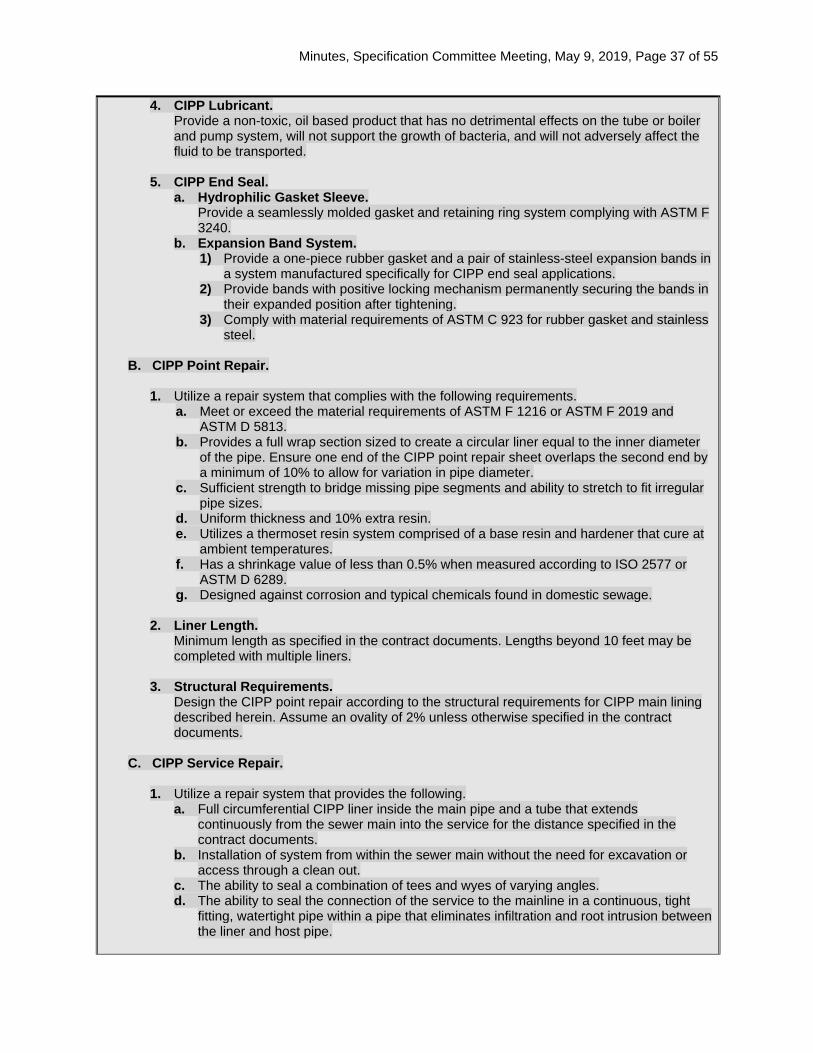
Minutes, Specification Committee Meeting, May 9, 2019, Page 37 of 55
4. CIPP Lubricant. Provide a non-toxic, oil based product that has no detrimental effects on the tube or boiler and pump system, will not support the growth of bacteria, and will not adversely affect the fluid to be transported.
5. CIPP End Seal. a. Hydrophilic Gasket Sleeve.
Provide a seamlessly molded gasket and retaining ring system complying with ASTM F 3240.
b. Expansion Band System. 1) Provide a one-piece rubber gasket and a pair of stainless-steel expansion bands in
a system manufactured specifically for CIPP end seal applications. 2) Provide bands with positive locking mechanism permanently securing the bands in
their expanded position after tightening. 3) Comply with material requirements of ASTM C 923 for rubber gasket and stainless
steel.
B. CIPP Point Repair.
1. Utilize a repair system that complies with the following requirements. a. Meet or exceed the material requirements of ASTM F 1216 or ASTM F 2019 and
ASTM D 5813. b. Provides a full wrap section sized to create a circular liner equal to the inner diameter
of the pipe. Ensure one end of the CIPP point repair sheet overlaps the second end by a minimum of 10% to allow for variation in pipe diameter.
c. Sufficient strength to bridge missing pipe segments and ability to stretch to fit irregular pipe sizes.
d. Uniform thickness and 10% extra resin. e. Utilizes a thermoset resin system comprised of a base resin and hardener that cure at
ambient temperatures. f. Has a shrinkage value of less than 0.5% when measured according to ISO 2577 or
ASTM D 6289. g. Designed against corrosion and typical chemicals found in domestic sewage.
2. Liner Length.
Minimum length as specified in the contract documents. Lengths beyond 10 feet may be completed with multiple liners.
3. Structural Requirements. Design the CIPP point repair according to the structural requirements for CIPP main lining described herein. Assume an ovality of 2% unless otherwise specified in the contract documents.
C. CIPP Service Repair.
1. Utilize a repair system that provides the following. a. Full circumferential CIPP liner inside the main pipe and a tube that extends
continuously from the sewer main into the service for the distance specified in the contract documents.
b. Installation of system from within the sewer main without the need for excavation or access through a clean out.
c. The ability to seal a combination of tees and wyes of varying angles. d. The ability to seal the connection of the service to the mainline in a continuous, tight
fitting, watertight pipe within a pipe that eliminates infiltration and root intrusion between the liner and host pipe.
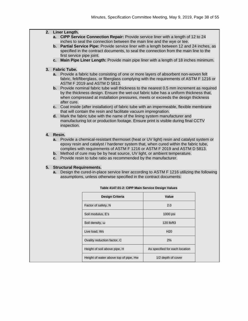
Minutes, Specification Committee Meeting, May 9, 2019, Page 38 of 55
2. Liner Length. a. CIPP Service Connection Repair: Provide service liner with a length of 12 to 24
inches to seal the connection between the main line and the wye or tee. b. Partial Service Pipe: Provide service liner with a length between 12 and 24 inches, as
specified in the contract documents, to seal the connection from the main line to the first service pipe joint.
c. Main Pipe Liner Length: Provide main pipe liner with a length of 18 inches minimum.
3. Fabric Tube. a. Provide a fabric tube consisting of one or more layers of absorbent non-woven felt
fabric, felt/fiberglass, or fiberglass complying with the requirements of ASTM F 1216 or ASTM F 2019 and ASTM D 5813.
b. Provide nominal fabric tube wall thickness to the nearest 0.5 mm increment as required by the thickness design. Ensure the wet-out fabric tube has a uniform thickness that, when compressed at installation pressures, meets or exceeds the design thickness after cure.
c. Coat inside (after installation) of fabric tube with an impermeable, flexible membrane that will contain the resin and facilitate vacuum impregnation.
d. Mark the fabric tube with the name of the lining system manufacturer and manufacturing lot or production footage. Ensure print is visible during final CCTV inspection.
4. Resin.
a. Provide a chemical-resistant thermoset (heat or UV light) resin and catalyst system or epoxy resin and catalyst / hardener system that, when cured within the fabric tube, complies with requirements of ASTM F 1216 or ASTM F 2019 and ASTM D 5813.
b. Method of cure may be by heat source, UV light, or ambient temperature. c. Provide resin to tube ratio as recommended by the manufacturer.
5. Structural Requirements.
a. Design the cured-in-place service liner according to ASTM F 1216 utilizing the following assumptions, unless otherwise specified in the contract documents:
Table 4147.01-2: CIPP Main Service Design Values
Design Criteria Value
Factor of safety, N 2.0
Soil modulus, E’s 1000 psi
Soil density, ω 120 lb/ft3
Live load, Ws H20
Ovality reduction factor, C 2%
Height of soil above pipe, H As specified for each location
Height of water above top of pipe, Hw 1/2 depth of cover
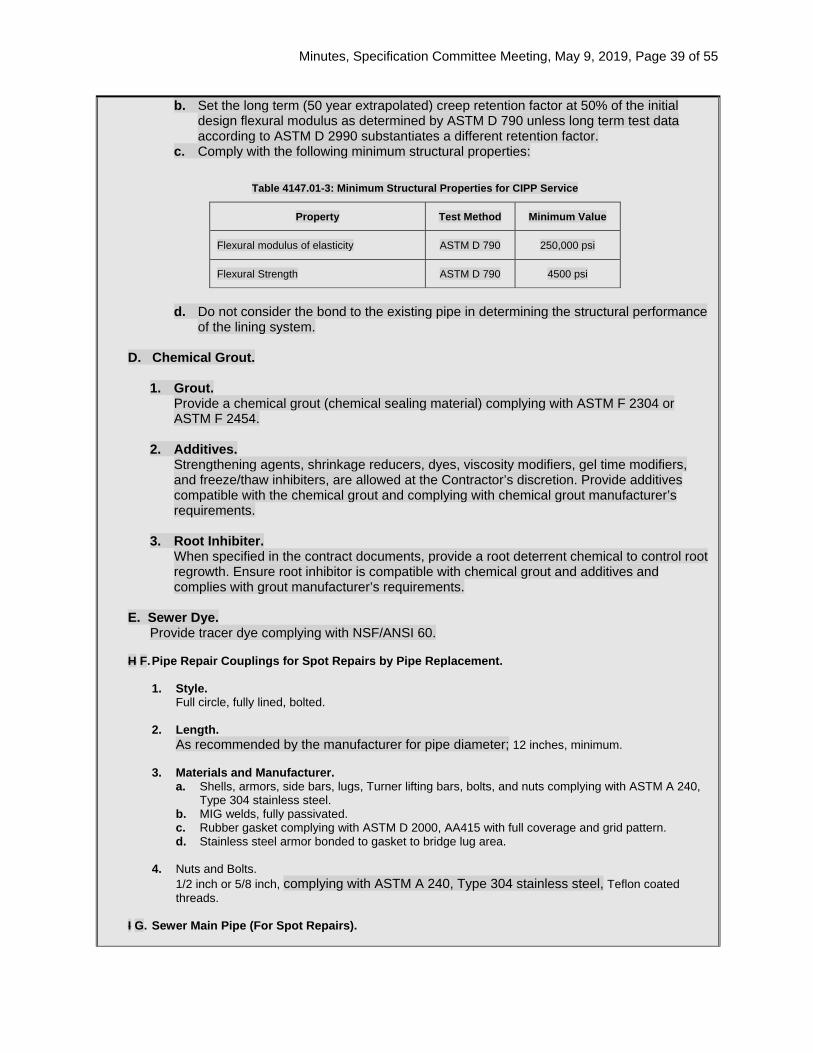
Minutes, Specification Committee Meeting, May 9, 2019, Page 39 of 55
b. Set the long term (50 year extrapolated) creep retention factor at 50% of the initial design flexural modulus as determined by ASTM D 790 unless long term test data according to ASTM D 2990 substantiates a different retention factor.
c. Comply with the following minimum structural properties:
Table 4147.01-3: Minimum Structural Properties for CIPP Service
Property Test Method Minimum Value
Flexural modulus of elasticity ASTM D 790 250,000 psi
Flexural Strength ASTM D 790 4500 psi
d. Do not consider the bond to the existing pipe in determining the structural performance
of the lining system.
D. Chemical Grout.
1. Grout. Provide a chemical grout (chemical sealing material) complying with ASTM F 2304 or ASTM F 2454.
2. Additives. Strengthening agents, shrinkage reducers, dyes, viscosity modifiers, gel time modifiers, and freeze/thaw inhibiters, are allowed at the Contractor’s discretion. Provide additives compatible with the chemical grout and complying with chemical grout manufacturer’s requirements.
3. Root Inhibiter. When specified in the contract documents, provide a root deterrent chemical to control root regrowth. Ensure root inhibitor is compatible with chemical grout and additives and complies with grout manufacturer’s requirements.
E. Sewer Dye.
Provide tracer dye complying with NSF/ANSI 60. H F. Pipe Repair Couplings for Spot Repairs by Pipe Replacement.
1. Style.
Full circle, fully lined, bolted.
2. Length. As recommended by the manufacturer for pipe diameter; 12 inches, minimum.
3. Materials and Manufacturer.
a. Shells, armors, side bars, lugs, Turner lifting bars, bolts, and nuts complying with ASTM A 240, Type 304 stainless steel.
b. MIG welds, fully passivated. c. Rubber gasket complying with ASTM D 2000, AA415 with full coverage and grid pattern. d. Stainless steel armor bonded to gasket to bridge lug area.
4. Nuts and Bolts. 1/2 inch or 5/8 inch, complying with ASTM A 240, Type 304 stainless steel, Teflon coated threads.
I G. Sewer Main Pipe (For Spot Repairs).

Minutes, Specification Committee Meeting, May 9, 2019, Page 40 of 55
1. Apply Section 2504. 2. Use materials for pipe replacement as specified in the contract documents or approved by the
Engineer. 4147.02 MANHOLE REHABILITATION.
A. Rubber Chimney Seal.
Apply Article 4149.02, J, for external and internal rubber chimney seals.
B. Urethane Chimney Seal. 1. Use only when specified in the contract documents. 2. Comply with Table 4147.02-1 for the physical properties:
Table 4147.02-1: Physical Properties
Property ASTM Test Method Acceptable Value
Elongation D 412 800%, minimum Tensile Strength D 412 1150 psi, minimum Adhesive Strength D 903 175 lb/in, minimum Pressure Resistance C 1244 2 minutes
C. In-Situ Manhole Replacement, Cast-in-place Concrete.
1. Forming System.
Provide an internal forming system capable of forming a new and structurally independent manhole wall within the existing manhole, with the specified thickness and conforming to the general shape of the existing manhole.
2. Concrete. Type I/II Portland cement with 5/8 inch minus coarse aggregate with fiber reinforcement and water reducer, 4000 psi minimum 28 day compressive strength or as approved by the Engineer.
3. Plastic Liner. When specified, provide a PVC or PE plastic liner resistant to degradation by sulfuric acid. Use a liner capable of being attached to the exterior of the forming system during erection of the forms. Use a plastic liner with a ribbed or studded exterior surface suitable for anchoring to the newly formed interior wall.
4. Casting. Provide new casting. Apply Article 4149.02, I.
D. Centrifugally Cast Cementitious Mortar Liner with Epoxy Seal. 1. Cementitious Lining.
a. Use a high-strength, high-build, corrosion-resistant mortar, based on Portland cement fortified with micro silica. Mixed mortar is to have a paste-like consistency that may be sprayed, cast, pumped, or gravity-flowed into any area 1/2 inch and larger.
b. Comply with Table 4147.02-2 for physical properties:
Table 4147.02-2: Physical Properties
Property Value
Unit Weight 125 102-130 pcf
Set Time at 70° F ASTM C 403
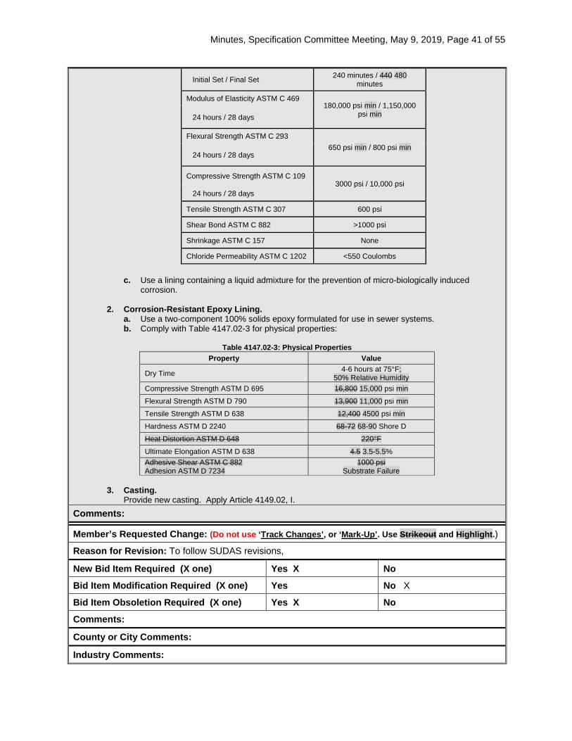
Minutes, Specification Committee Meeting, May 9, 2019, Page 41 of 55
Initial Set / Final Set 240 minutes / 440 480 minutes
Modulus of Elasticity ASTM C 469 180,000 psi min / 1,150,000
psi min 24 hours / 28 days
Flexural Strength ASTM C 293 650 psi min / 800 psi min
24 hours / 28 days
Compressive Strength ASTM C 109 3000 psi / 10,000 psi
24 hours / 28 days
Tensile Strength ASTM C 307 600 psi
Shear Bond ASTM C 882 >1000 psi
Shrinkage ASTM C 157 None
Chloride Permeability ASTM C 1202 <550 Coulombs
c. Use a lining containing a liquid admixture for the prevention of micro-biologically induced
corrosion.
2. Corrosion-Resistant Epoxy Lining. a. Use a two-component 100% solids epoxy formulated for use in sewer systems. b. Comply with Table 4147.02-3 for physical properties:
Table 4147.02-3: Physical Properties
Property Value
Dry Time 4-6 hours at 75°F; 50% Relative Humidity
Compressive Strength ASTM D 695 16,800 15,000 psi min Flexural Strength ASTM D 790 13,900 11,000 psi min Tensile Strength ASTM D 638 12,400 4500 psi min Hardness ASTM D 2240 68-72 68-90 Shore D Heat Distortion ASTM D 648 220°F Ultimate Elongation ASTM D 638 4.5 3.5-5.5% Adhesive Shear ASTM C 882 Adhesion ASTM D 7234
1000 psi Substrate Failure
3. Casting.
Provide new casting. Apply Article 4149.02, I. Comments:
Member’s Requested Change: (Do not use ‘Track Changes’, or ‘Mark-Up’. Use Strikeout and Highlight.)
Reason for Revision: To follow SUDAS revisions,
New Bid Item Required (X one) Yes X No
Bid Item Modification Required (X one) Yes No X
Bid Item Obsoletion Required (X one) Yes X No
Comments:
County or City Comments:
Industry Comments:

Minutes, Specification Committee Meeting, May 9, 2019, Page 42 of 55
Minutes, Specification Committee Meeting, May 9, 2019, Page 43 of 55
Form 510130 (08-15)
SPECIFICATION REVISION SUBMITTAL FORM Submitted by: Wes Musgrove / Melissa Serio Office: Construction & Materials Item 5
Submittal Date: 4/22/19 Proposed Effective Date: October 2019 GS
Article No.: 4169.12, A Title: General (Perimeter and Slope Sediment Control Device)
Other:
Specification Committee Action: Withdrawn
Deferred: Not Approved: Approved Date: Effective Date:
Specification Committee Approved Text:
Comments: The request was withdrawn at this time to see if any other manufacturers come forward to produce sediment logs. The Construction and Materials Bureau found one manufacturer that is interested in being added to MAPLE but needs to add a waterproof tag and find a local supplier. There may be others, including the company whose facility burned, but they have not yet respond to requests for information. The Committee asked the Contracts and Specifications Bureau to investigate whether prices had gone up since there has only been one available supplier of sediment logs. The graph of bid prices since the requirement went into effect is attached. This does not show any relative spikes in cost due to the sole source issue for sediment logs, only normal variation. The fire at the facility was in early 2017, so some time later that year, the supply from them would have run out. The Construction and Materials Bureau will put together a Public Interest Finding Memo to justify only having one current supplier of sediment logs. If we don’t get at least one new supplier added soon, we will make the requested change either to the specifications or by proposal note.
Specification Section Recommended Text: 4169.12, A, General.
Delete the first sentence: Interstate and Primary highway projects shall use sediment logs only.
4169.12, A, 5.
Replace the Article: Approved sediment logs, are listed in Materials I.M. 469.10, Appendix E. Wwattles, and filter socks will be accepted based on the manufacturer’s certification.
Comments:
Member’s Requested Change: (Do not use ‘Track Changes’, or ‘Mark-Up’. Use Strikeout and Highlight.) 4169.12, A, 1. and 4169.12, A, 5.
Replace Articles:
Minutes, Specification Committee Meeting, May 9, 2019, Page 44 of 55
4169.12 PERIMETER AND SLOPE SEDIMENT CONTROL DEVICE. A. General.
Interstate and Primary highway projects shall use sediment logs only.
1. Provide wattles, sediment logs, and filter socks consisting of the following materials contained in a tube of photo degradable fabric or synthetic netting: a. Wattles: Cereal straw or native grass straw certified by the Iowa Crop Improvement Association
or other state’s Crop Improvement Associations as Certified Noxious Weed Seed Free Mulch. Wattles with observed seed heads will not be accepted.
b. Sediment logs: Wood excelsior fibers with 80% of the wood excelsior fibers being 6 inches long or longer.
c. Filter socks: Compost (from an approved source meeting Article 4169.08), wood chips, or mulch.
And 5. Approved sediment logs are listed in Materials I.M. 469.10, Appendix E. Wwattles, sediment logs,
and filter socks will be accepted based on the manufacturer’s certification. Reason for Revision: Remove restriction that allows only sediment logs on interstate and primary projects. This restriction has been in effect since October 2016 GS. Due to a fire at a manufacturer’s facility (with no plans to re-enter the market), sediment logs are currently sole source.
New Bid Item Required (X one) Yes No x
Bid Item Modification Required (X one) Yes No x
Bid Item Obsoletion Required (X one) Yes No x
Comments: None
County or City Comments:
Industry Comments:
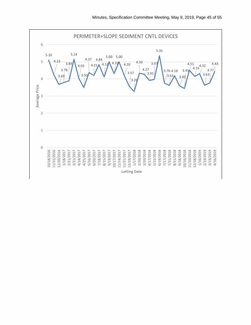
Minutes, Specification Committee Meeting, May 9, 2019, Page 45 of 55
5.10
4.23
3.69
3.78
3.89
5.14
4.03
3.50
4.37
4.214.84
4.12
5.00
4.32
5.00
4.20
3.57
3.26
4.33
4.273.91
3.97
5.35
3.763.63
4.18
3.60
3.45
4.514.15
4.32
3.633.77
4.43
0
1
2
3
4
5
610
/18/
2016
11/1
5/20
1612
/20/
2016
1/18
/201
72/
21/2
017
3/21
/201
74/
18/2
017
4/25
/201
75/
16/2
017
6/20
/201
77/
18/2
017
8/15
/201
79/
19/2
017
10/1
7/20
1711
/14/
2017
11/2
1/20
1712
/19/
2017
1/17
/201
82/
20/2
018
3/20
/201
84/
17/2
018
5/15
/201
86/
19/2
018
7/17
/201
87/
31/2
018
8/21
/201
89/
18/2
018
10/1
6/20
1811
/20/
2018
12/1
8/20
181/
16/2
019
2/19
/201
93/
19/2
019
4/16
/201
9
Aver
age
Pric
e
Letting Date
PERIMETER+SLOPE SEDIMENT CNTL DEVICES

Minutes, Specification Committee Meeting, May 9, 2019, Page 46 of 55
Form 510130 (08-15)
SPECIFICATION REVISION SUBMITTAL FORM Submitted by: Eric Johnsen / Tom Reis Office: Specifications Item 6
Submittal Date: Proposed Effective Date:
Article No.: 2316.02, A, 1 Title: General (Pavement Smoothness)
Other:
Specification Committee Action: Approved as recommended.
Deferred: Not Approved: Approved Date: 5/9/2019 Effective Date: 10/15/2019
Specification Committee Approved Text: See Specification Section Recommended Text.
Comments: None.
Specification Section Recommended Text: 2304.03, A, 3.
Delete the Article: 3. Apply Article 2316.02, A, 7.
2316.02, A, General.
Replace the first sentence: Evaluate pavement smoothness for all Interstate and Primary main line pavement surfaces, and all other road surfaces included on Primary projects, except when specifically excluded or modified by the contract documents.
Comments:
Member’s Requested Change: (Do not use ‘Track Changes’, or ‘Mark-Up’. Use Strikeout and Highlight.)
Reason for Revision: Eliminate an unnecessary reference that caused some confusion. Clean up some confusing language since most Interstate and Primary pavement is evaluated according to Section 2317.
New Bid Item Required (X one) Yes No X
Bid Item Modification Required (X one) Yes No X
Bid Item Obsoletion Required (X one) Yes No X
Comments:
County or City Comments:
Industry Comments:

Minutes, Specification Committee Meeting, May 9, 2019, Page 47 of 55
Form 510130 (08-15)
SPECIFICATION REVISION SUBMITTAL FORM Submitted by: Willy Sorenson Office: Traffic and Safety Item 7
Submittal Date: May 1, 2019 Proposed Effective Date: October 15, 2019
Article No.: 2528.03.M & 4188.09 (New) Title: Speed Feedback Trailers (Highway Signing)
Other:
Specification Committee Action: Approved with changes.
Deferred: Not Approved: Approved Date: 5/9/2019 Effective Date: 10/15/2019
Specification Committee Approved Text: 2528.03, Construction.
Add the Article: M. Speed Feedback Signs.
Furnish, place, operate, and maintain speed feedback signs at locations shown on the contract documents. Ensure all speed feedback signs meet the current requirements of the MUTCD and Section 4188.
1. Definitions.
a. Speed Feedback Trailer. Speed feedback trailers are mobile devices using speed feedback signs to capture vehicle speed for oncoming traffic.
b. Display. The display is a device connecting to the speed feedback trailer capable of broadcasting the speed of oncoming traffic captured by the speed feedback sign. This device allows for vehicle speed feedback to the vehicle operator, allowing for speed adjustment throughout the remainder of the work zone.
2. Testing and Configuration. a. At least 1 week before speed feedback trailer is deployed to a project, a testing
and configuration meeting with the Engineer shall be held. b. The Contractor, in conjunction with the Engineer, will perform necessary
configuration adjustments to the speed feedback trailer.
3. Maintenance. a. Provide preventive maintenance necessary to achieve uninterrupted service. b. Verify operational status each day as part of the daily diary and notify Engineer
when a problem is detected. c. Provide unscheduled maintenance or total replacement of sign when sign is
unable to display a message adequately within 24 hours of notification. Action shall be taken to resolve the following problems if they have been visually observed or confirmed by self diagnostics by the speed feedback trailer for 3 continuous days or 7 intermittent days over a 2 week period. 1) An entire pixel board is showing failure. 2) Five or more pixel failures over entire message panel anytime while sign is
deployed for use (blank or displaying a message). 3) Two or more pixel failures in any character when displaying the speed.
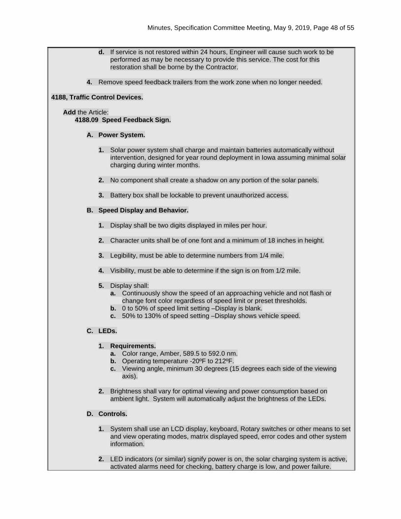
Minutes, Specification Committee Meeting, May 9, 2019, Page 48 of 55
d. If service is not restored within 24 hours, Engineer will cause such work to be performed as may be necessary to provide this service. The cost for this restoration shall be borne by the Contractor.
4. Remove speed feedback trailers from the work zone when no longer needed.
4188, Traffic Control Devices.
Add the Article: 4188.09 Speed Feedback Sign.
A. Power System.
1. Solar power system shall charge and maintain batteries automatically without
intervention, designed for year round deployment in Iowa assuming minimal solar charging during winter months.
2. No component shall create a shadow on any portion of the solar panels. 3. Battery box shall be lockable to prevent unauthorized access.
B. Speed Display and Behavior.
1. Display shall be two digits displayed in miles per hour. 2. Character units shall be of one font and a minimum of 18 inches in height. 3. Legibility, must be able to determine numbers from 1/4 mile. 4. Visibility, must be able to determine if the sign is on from 1/2 mile. 5. Display shall:
a. Continuously show the speed of an approaching vehicle and not flash or change font color regardless of speed limit or preset thresholds.
b. 0 to 50% of speed limit setting –Display is blank. c. 50% to 130% of speed setting –Display shows vehicle speed.
C. LEDs.
1. Requirements.
a. Color range, Amber, 589.5 to 592.0 nm. b. Operating temperature -20ºF to 212ºF. c. Viewing angle, minimum 30 degrees (15 degrees each side of the viewing
axis). 2. Brightness shall vary for optimal viewing and power consumption based on
ambient light. System will automatically adjust the brightness of the LEDs. D. Controls.
1. System shall use an LCD display, keyboard, Rotary switches or other means to set
and view operating modes, matrix displayed speed, error codes and other system information.
2. LED indicators (or similar) signify power is on, the solar charging system is active,
activated alarms need for checking, battery charge is low, and power failure.

Minutes, Specification Committee Meeting, May 9, 2019, Page 49 of 55
E. Operating Modes.
1. Off.
Except for the charging system the entire unit is off. Solar panels will continue to charge batteries in this position.
2. Run.
Normal operating mode.
3. Speed Limit Settings. 10 to 70 mph in 5 mph increments.
F. Radar.
1. K-Band, approach-only senses the largest, nearest mass moving toward it. 2. 10 to 99 mph speed range. 3. 1000 foot range. 4. Centered antenna head for maximum effectiveness regardless of which side of
road the trailer is being used. G. Regulatory Sign.
1. System shall include a regulatory speed limit sign with interchangeable speed limit
numbers. Numbers shall be supplied in quantities necessary to display a speed range of 10 to 70 mph in 5 mph increments.
2. Sign Requirements.
a. Size: 30 inches by 36 inches (W x H). b. Color: Black characters on white background. c. Mounting Height: Minimum 5 feet measured from ground to bottom of sign. d. Material: 0.063 inch minimum, tempered aluminum sheet with high-intensity
reflective coating.
Comments: The Design Bureau noted that the Road Standards use the terminology “speed feedback sign” instead of trailer. This was in case a Contractor wanted to install a post mounted sign for a long term installation. The Committee felt this would not be feasible, as they have not been crash tested and the battery and solar panel would be difficult to mount or secure. The Article headers were changed to Speed Feedback Signs for consistency, but the definition mentions that they are trailer mounted. References to the Engineer controlling the signs were removed. The signs will be under the control of the Contractor, with the Engineer consulting with them. Possession of the trailers following construction will remain with the Contractor, but the Committee felt this language was unnecessary. A statement was added that the Contractor shall remove the trailers when no longer required on a project. The Committee discussed including reference to the speed feedback trailers in the basis of payment for Traffic Control, since we have been bidding them when using the special provision. It was felt that there are other elements of traffic control that are included and we can’t call out all of them. The road standards that require speed feedback signs note that the only bid item included is Traffic Control.
Specification Section Recommended Text: 2528.03, Construction.
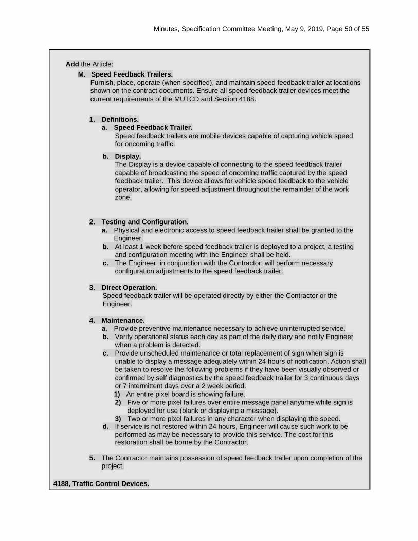
Minutes, Specification Committee Meeting, May 9, 2019, Page 50 of 55
Add the Article:
M. Speed Feedback Trailers. Furnish, place, operate (when specified), and maintain speed feedback trailer at locations shown on the contract documents. Ensure all speed feedback trailer devices meet the current requirements of the MUTCD and Section 4188.
1. Definitions.
a. Speed Feedback Trailer. Speed feedback trailers are mobile devices capable of capturing vehicle speed for oncoming traffic.
b. Display. The Display is a device capable of connecting to the speed feedback trailer capable of broadcasting the speed of oncoming traffic captured by the speed feedback trailer. This device allows for vehicle speed feedback to the vehicle operator, allowing for speed adjustment throughout the remainder of the work zone.
2. Testing and Configuration. a. Physical and electronic access to speed feedback trailer shall be granted to the
Engineer. b. At least 1 week before speed feedback trailer is deployed to a project, a testing
and configuration meeting with the Engineer shall be held. c. The Engineer, in conjunction with the Contractor, will perform necessary
configuration adjustments to the speed feedback trailer.
3. Direct Operation. Speed feedback trailer will be operated directly by either the Contractor or the Engineer.
4. Maintenance.
a. Provide preventive maintenance necessary to achieve uninterrupted service. b. Verify operational status each day as part of the daily diary and notify Engineer
when a problem is detected. c. Provide unscheduled maintenance or total replacement of sign when sign is
unable to display a message adequately within 24 hours of notification. Action shall be taken to resolve the following problems if they have been visually observed or confirmed by self diagnostics by the speed feedback trailer for 3 continuous days or 7 intermittent days over a 2 week period. 1) An entire pixel board is showing failure. 2) Five or more pixel failures over entire message panel anytime while sign is
deployed for use (blank or displaying a message). 3) Two or more pixel failures in any character when displaying the speed.
d. If service is not restored within 24 hours, Engineer will cause such work to be performed as may be necessary to provide this service. The cost for this restoration shall be borne by the Contractor.
5. The Contractor maintains possession of speed feedback trailer upon completion of the
project. 4188, Traffic Control Devices.
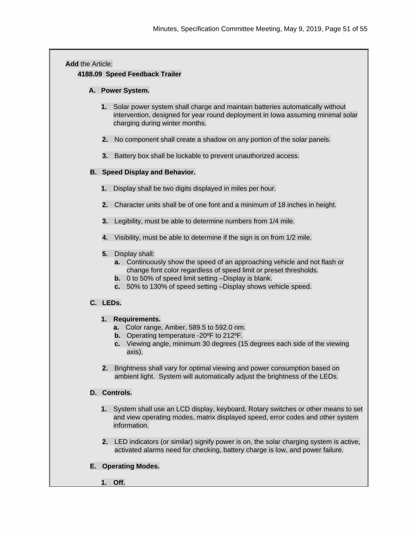
Minutes, Specification Committee Meeting, May 9, 2019, Page 51 of 55
Add the Article:
4188.09 Speed Feedback Trailer
A. Power System.
1. Solar power system shall charge and maintain batteries automatically without intervention, designed for year round deployment in Iowa assuming minimal solar charging during winter months.
2. No component shall create a shadow on any portion of the solar panels. 3. Battery box shall be lockable to prevent unauthorized access.
B. Speed Display and Behavior.
1. Display shall be two digits displayed in miles per hour. 2. Character units shall be of one font and a minimum of 18 inches in height. 3. Legibility, must be able to determine numbers from 1/4 mile. 4. Visibility, must be able to determine if the sign is on from 1/2 mile. 5. Display shall:
a. Continuously show the speed of an approaching vehicle and not flash or change font color regardless of speed limit or preset thresholds.
b. 0 to 50% of speed limit setting –Display is blank. c. 50% to 130% of speed setting –Display shows vehicle speed.
C. LEDs.
1. Requirements.
a. Color range, Amber, 589.5 to 592.0 nm. b. Operating temperature -20ºF to 212ºF. c. Viewing angle, minimum 30 degrees (15 degrees each side of the viewing
axis). 2. Brightness shall vary for optimal viewing and power consumption based on
ambient light. System will automatically adjust the brightness of the LEDs. D. Controls.
1. System shall use an LCD display, keyboard, Rotary switches or other means to set
and view operating modes, matrix displayed speed, error codes and other system information.
2. LED indicators (or similar) signify power is on, the solar charging system is active,
activated alarms need for checking, battery charge is low, and power failure. E. Operating Modes.
1. Off.
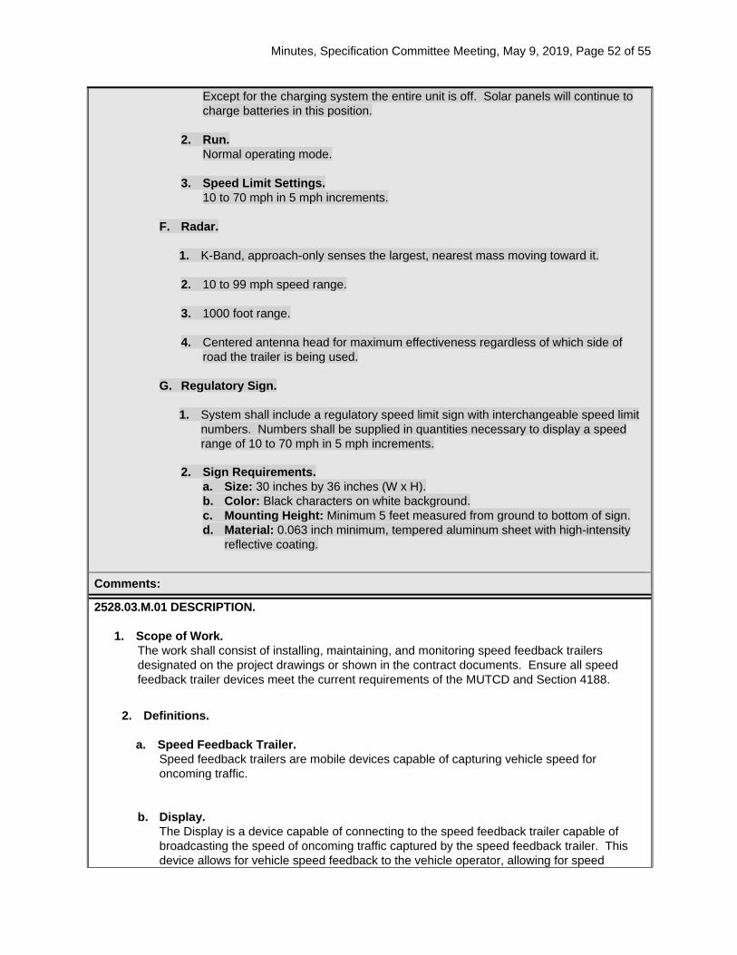
Minutes, Specification Committee Meeting, May 9, 2019, Page 52 of 55
Except for the charging system the entire unit is off. Solar panels will continue to charge batteries in this position.
2. Run.
Normal operating mode.
3. Speed Limit Settings. 10 to 70 mph in 5 mph increments.
F. Radar.
1. K-Band, approach-only senses the largest, nearest mass moving toward it. 2. 10 to 99 mph speed range. 3. 1000 foot range. 4. Centered antenna head for maximum effectiveness regardless of which side of
road the trailer is being used. G. Regulatory Sign.
1. System shall include a regulatory speed limit sign with interchangeable speed limit
numbers. Numbers shall be supplied in quantities necessary to display a speed range of 10 to 70 mph in 5 mph increments.
2. Sign Requirements.
a. Size: 30 inches by 36 inches (W x H). b. Color: Black characters on white background. c. Mounting Height: Minimum 5 feet measured from ground to bottom of sign. d. Material: 0.063 inch minimum, tempered aluminum sheet with high-intensity
reflective coating.
Comments:
2528.03.M.01 DESCRIPTION.
1. Scope of Work. The work shall consist of installing, maintaining, and monitoring speed feedback trailers designated on the project drawings or shown in the contract documents. Ensure all speed feedback trailer devices meet the current requirements of the MUTCD and Section 4188.
2. Definitions.
a. Speed Feedback Trailer.
Speed feedback trailers are mobile devices capable of capturing vehicle speed for oncoming traffic.
b. Display. The Display is a device capable of connecting to the speed feedback trailer capable of broadcasting the speed of oncoming traffic captured by the speed feedback trailer. This device allows for vehicle speed feedback to the vehicle operator, allowing for speed
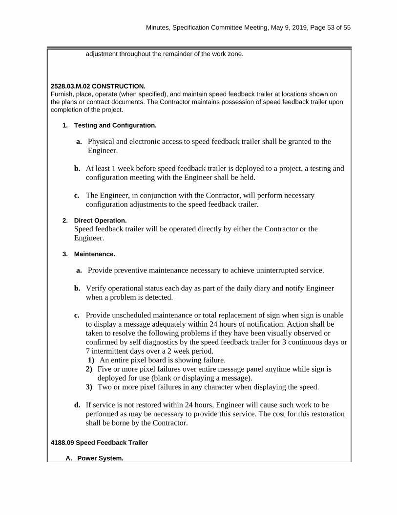
Minutes, Specification Committee Meeting, May 9, 2019, Page 53 of 55
adjustment throughout the remainder of the work zone.
2528.03.M.02 CONSTRUCTION. Furnish, place, operate (when specified), and maintain speed feedback trailer at locations shown on the plans or contract documents. The Contractor maintains possession of speed feedback trailer upon completion of the project.
1. Testing and Configuration.
a. Physical and electronic access to speed feedback trailer shall be granted to the
Engineer. b. At least 1 week before speed feedback trailer is deployed to a project, a testing and
configuration meeting with the Engineer shall be held.
c. The Engineer, in conjunction with the Contractor, will perform necessary configuration adjustments to the speed feedback trailer.
2. Direct Operation.
Speed feedback trailer will be operated directly by either the Contractor or the Engineer.
3. Maintenance.
a. Provide preventive maintenance necessary to achieve uninterrupted service.
b. Verify operational status each day as part of the daily diary and notify Engineer
when a problem is detected.
c. Provide unscheduled maintenance or total replacement of sign when sign is unable to display a message adequately within 24 hours of notification. Action shall be taken to resolve the following problems if they have been visually observed or confirmed by self diagnostics by the speed feedback trailer for 3 continuous days or 7 intermittent days over a 2 week period. 1) An entire pixel board is showing failure.
2) Five or more pixel failures over entire message panel anytime while sign is deployed for use (blank or displaying a message).
3) Two or more pixel failures in any character when displaying the speed.
d. If service is not restored within 24 hours, Engineer will cause such work to be performed as may be necessary to provide this service. The cost for this restoration shall be borne by the Contractor.
4188.09 Speed Feedback Trailer
A. Power System.

Minutes, Specification Committee Meeting, May 9, 2019, Page 54 of 55
1. Solar power system shall charge and maintain batteries automatically without
intervention, designed for year round deployment in Iowa assuming minimal solar charging during winter months.
2. No component shall create a shadow on any portion of the solar panels.
3. Battery box shall be lockable to prevent unauthorized access.
B. Speed Display and Behavior.
1. Display shall be two digits displayed in miles per hour.
2. Character units shall be of one font and a minimum of 18 24 inches in height.
3. Legibility, must be able to determine numbers from 1/4 mile.
4. Visibility, must be able to determine if the sign is on from 1/2 mile.
5. Display shall have the ability to:
a. Continuously show the speed of an approaching vehicle and not flash or change font color regardless of speed limit or preset thresholds.
b. 0 to 50% of speed limit setting –Display is blank. c. 50% to 130% of speed setting –Display shows vehicle speed.
C. LEDs.
1. Requirements.
a. Color range, Amber, 589.5 to 592.0 nm. b. Operating temperature -20ºF to 212ºF. c. Viewing angle, minimum 30 degrees (15 degrees each side of the viewing axis).
2. Brightness shall vary for optimal viewing and power consumption based on
ambient light. System will automatically adjust the brightness of the LEDs.
D. Controls. 1. System shall use an LCD display, keyboard, Rotary switches or other means to set
and view operating modes, matrix displayed speed, error codes and other system information.
2. LED indicators (or similar) signify power is on, the solar charging system is active,
activated alarms need for checking, battery charge is low, and power failure.
E. Operating Modes. 1. Off.

Minutes, Specification Committee Meeting, May 9, 2019, Page 55 of 55
Except for the charging system the entire unit is off. Solar panels will continue to charge batteries in this position.
2. Run. Normal operating mode.
3. Speed Limit Settings.
10 to 70 mph in 5 mph increments.
F. Radar. 1. K-Band, approach-only senses the largest, nearest mass moving toward it.
2. 10 to 99 mph speed range.
3. 1000 foot range.
4. Centered antenna head for maximum effectiveness regardless of which side of road
the trailer is being used.
G. Regulatory Sign. 1. System shall include a regulatory speed limit sign with interchangeable speed limit
numbers. Numbers shall be supplied in quantities necessary to display a speed range of 10 to 70 mph in 5 mph increments. Numbers not in use shall store in the trailer’s battery box.
2. Sign Requirements.
a. Size, 30 inches by 36 inches (W x H) b. Color, black characters on white background. c. Mounting Height, minimum 5 feet measured from ground to bottom of sign. d. Material, 0.063 inch minimum, tempered aluminum sheet with high-intensity
reflective coating. Reason for Revision: Speed feedback trailers are being added to TC-418, TC-421 and TC-422 and therefore need to ne part of the General Specifications. They previously were added by SP only to a project.
New Bid Item Required (X one) Yes No X
Bid Item Modification Required (X one) Yes No X
Bid Item Obsoletion Required (X one) Yes No X
Comments:
County or City Comments:
Industry Comments: