Embed Size (px)
Citation preview
MINT™ Programming Guide
FOR: SMARTMOVESMARTSTEPEUROSYSTEMEUROSERVOEUROSTEP
MN12607/98

i7/98
MINT™ Programming Guide
For: SmartMoveSmartStepEuroSystemEuroServoEuroStep
MN1260

ii 7/98
Copyright Optimized Control Ltd 1988-97.
All rights reserved.
This manual is copyrighted and all rights are reserved. This document may not,inwhole or in part,be copied or reproduced in any form without the prior writtenconsent of Baldor Optimized Control.
Baldor Optimized Control makes no representations or warranties with respect tothe contents hereof and specifically disclaims any implied warranties of fitness forany particular purpose. The information in this document is subject to changewithout notice. Baldor Optimized Control assumes no responsibility for any errorsthat may appear in this document.
MINT™ is a registered trademark of Baldor Optimized Control Ltd.
Baldor Optimized Control Ltd178-180 Hotwell RoadBristolBS8 4RPU.K.
Baldor Electric CompanyTelephone: +1 501 646 4711Fax: +1 501 648 5792email: [email protected]
Telephone: +44 (0)117 987 3100Fax: +44 (0)117 987 3101email: [email protected] site: www.baldor.co.uk
Baldor ASR GmbHTelephone: +49 (0)89 90508-0Fax: +49 (0)89 90508-492
Baldor ASR AGTelephone: +41 (0)52 647 4700Fax: +41 (0)52 659 2394
Australian Baldor Pty LtdTelephone: +61 2 9674 5455Fax: +61 2 9674 2495
Baldor Electric (F.E.) Pte LtdTelephone: +65 744 2572Fax: +65 747 1708
MN1260

iii7/98
Technical Support
When asking for technical support regarding software, please make sure you have thefollowing information available:
• The controller name.
• RS232 or RS485 serial communications used.
• Version of MINT. This can be found by typing VER at the command line or byreading the EPROM label.
MN1260
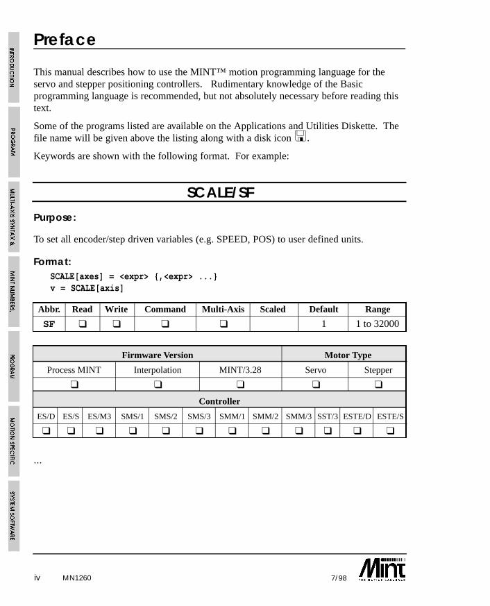
SCALE/SF
Purpose:
To set all encoder/step driven variables (e.g. SPEED, POS) to user defined units.
Format:SCALE[axes] = <expr> {,<expr> ...}v = SCALE[axis]
Abbr. Read Write Command Multi-Axis Scaled Default Range
SF ❑ ❑ ❑ ❑ 1 1 to 32000
Firmware Version Motor Type
Process MINT Interpolation MINT/3.28 Servo Stepper
❑ ❑ ❑ ❑ ❑
Controller
ES/D ES/S ES/M3 SMS/1 SMS/2 SMS/3 SMM/1 SMM/2 SMM/3 SST/3 ESTE/D ESTE/S
❑ ❑ ❑ ❑ ❑ ❑ ❑ ❑ ❑ ❑ ❑ ❑
...
iv 7/98
Preface
This manual describes how to use the MINT™ motion programming language for theservo and stepper positioning controllers. Rudimentary knowledge of the Basicprogramming language is recommended, but not absolutely necessary before reading thistext.
Some of the programs listed are available on the Applications and Utilities Diskette. Thefile name will be given above the listing along with a disk icon <.
Keywords are shown with the following format. For example:
MN1260
v7/98
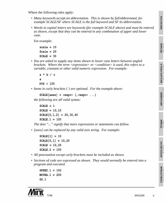
Where the following rules apply:
• Many keywords accept an abbreviation. This is shown by full/abbreviated, forexample SCALE/SF where SCALE is the full keyword and SF its abbreviation.
• Words in capital letters are keywords (for example SCALE above) and must be enteredas shown, except that they can be entered in any combination of upper and lowercase.
For example:
scale = 10Scale = 20
SCALE = 30
• You are asked to supply any items shown in lower case letters between angledbrackets. Where the term <expression> or <condition> is used, this refers to avariable, constant or other valid numeric expression. For example:
a * b / c
a
POS < 100
• Items in curly brackets { } are optional. For the example above:
SCALE[axes] = <expr> {,<expr> ...}
the following are all valid syntax:
SCALE = 1
SCALE = 10,10SCALE[0,1,2] = 20,30,40
SCALE.1 = 100
The dots “...” signify that more expressions or statements can follow.
• [axes] can be replaced by any valid axis string. For example:
SCALE[1] = 10
SCALE[0,1] = 10,20SCALE = 10,20
SCALE.2 = 100
• All punctuation except curly brackets must be included as shown.
• Sections of code are expressed as shown. They would normally be entered into aprogram and executed.
SPEED.1 = 100
MOVEA.1 = 200
GO.1
MN1260
vi 7/98MN1260
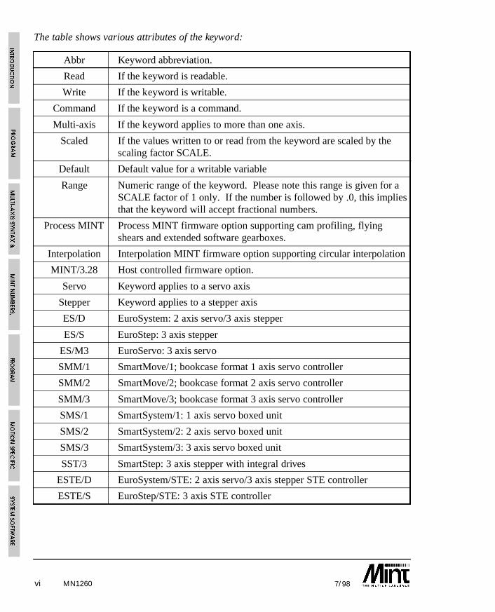
The table shows various attributes of the keyword:
Abbr Keyword abbreviation.
Read If the keyword is readable.
Write If the keyword is writable.
Command If the keyword is a command.
Multi-axis If the keyword applies to more than one axis.
Scaled If the values written to or read from the keyword are scaled by thescaling factor SCALE.
Default Default value for a writable variable
Range Numeric range of the keyword. Please note this range is given for aSCALE factor of 1 only. If the number is followed by .0, this impliesthat the keyword will accept fractional numbers.
Process MINT Process MINT firmware option supporting cam profiling, flyingshears and extended software gearboxes.
Interpolation Interpolation MINT firmware option supporting circular interpolation
MINT/3.28 Host controlled firmware option.
Servo Keyword applies to a servo axis
Stepper Keyword applies to a stepper axis
ES/D EuroSystem: 2 axis servo/3 axis stepper
ES/S EuroStep: 3 axis stepper
ES/M3 EuroServo: 3 axis servo
SMM/1 SmartMove/1; bookcase format 1 axis servo controller
SMM/2 SmartMove/2; bookcase format 2 axis servo controller
SMM/3 SmartMove/3; bookcase format 3 axis servo controller
SMS/1 SmartSystem/1: 1 axis servo boxed unit
SMS/2 SmartSystem/2: 2 axis servo boxed unit
SMS/3 SmartSystem/3: 3 axis servo boxed unit
SST/3 SmartStep: 3 axis stepper with integral drives
ESTE/D EuroSystem/STE: 2 axis servo/3 axis stepper STE controller
ESTE/S EuroStep/STE: 3 axis STE controller
vii7/98
SmartMove ControllersSmartMove is a new addition to the manual. Where it is not represented in the controllertable, it should be considered to be functionally equivalent to SmartSystem/3.
Stepper Only ControllersStepper only controllers use a subset of the MINT™ Programming Language. Allreferences to servo systems will be marked and should be ignored.
Related ManualsRefer to Manuals and Software for MINT Products on page 15-1.
Updates from Issue 11 to Issue 12The MINT Programming Manual has been updated to include a number of new keywordswhich have been introduced into esMINT v2.65 and above. At the time of writing, theversion of MINT is esMINT v2.71.
• esMINT v2.71 and above supports an OFFSET move on a FLY move.
• A deceleration parameter using the new DECEL keyword can be applied to apositional move or JOG. Both the acceleration and deceleration can now also bechanged on the fly. In order to maintain backwards compatibility, the decelerationterm must be ‘switched on’ using the new AXISCON keyword.
• The new FASTENC keyword latches the ENCODER position on a fast interrupt. Thiscan be useful in situations where the position of a rotary knife, for example, isrequired.
• Data capture routines are used to capture data such as following error and axisvelocity for display on a software oscilloscope. The data capture routine are used toassist in servo tuning. cTERM for Windows provides a graphing option to exploit thisfeature.
• A new expression parser has been incorporated giving a 10-15% speed improvementin the execution of expressions.
MN1260
viii 7/98
• The XENCODER keyword is supported as standard within the firmware (denoted bythe /X on the version number). In order to use the three channel encoder interfaceboard, the AXISCON keyword must be used to ‘switch’ it on. The 3 channel encoderboard can now be used as a master reference for cams and flying shears.
• In order to maximize the use of the memory card, array data can be stored off-line onthe memory card. This is given by the use of the new OFFLINE keyword. From thenon, the array is used in the same way as any other arrays stored locally in memory.
• The FOLLOW keyword is now able to follow the pulse timer input using theFOLLOWAXIS keyword. This allows position lock on the pulse input.
• The new BAUD keyword can be used to change the serial baud to any value between300 and 19,200. By default the controller powers up at 9600 baud.
• The ECHO keyword can be used to remove command line echo and error messages.
• The new TRIGGER keyword can be used to trigger moves off any of the 8 digitalinputs.
• A clutch distance can be defined for FOLLOW on axes 0 and 1. This is achieved bysetting a master increment distance using the MASTERINC keyword.
• The error handling capability of MINT has been extended with the introduction of theERR keywords. System run time errors such as “Out of Range” or “Motion inProgress” can be trapped within the #ONERROR routine.
• Torque mode (see TORQUE keyword) and JOG can be entered while motion is inprogress on the axis, without a “Motion in Progress” error resulting:
move type ( TORQUE
move type ( JOG
• It is now possible to switch between JOG and FOLLOW without a “Motion inProgress” error resulting:
JOG ( FOLLOW ( JOG ( FOLLOW
• Maximum following error detection can be turned off with the AXISCON keyword.
• Maximum following error (MFOLERR) has been increased from 16000 counts to32767 counts.
• A move can be cancelled on a stop input by using the STOPMODE keyword.
• The PRESCALE keyword allows the encoder input to be scaled down. Useful forwhere a high resolution encoder cannot be changed but greater absolute distance isrequired.
• GO will no longer issue “Motion in Progress” errors unnecessarily.
MN1260
ix7/98
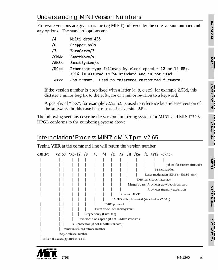
Understanding MINT Version NumbersFirmware versions are given a name (eg MINT) followed by the core version number andany options. The standard options are:
/4 Multi-drop 485
/S Stepper only
/3 EuroServo/3
/SMMx SmartMove/x/SMSx SmartSystem/x
/KCxx Processor type followed by clock speed - 12 or 14 MHz.KC16 is assumed to be standard and is not used.
-Jxxx Job number. Used to reference customized firmware.
If the version number is post-fixed with a letter (a, b, c etc), for example 2.53d, thisdictates a minor bug fix to the software or a minor revision to a keyword.
A post-fix of “.bX”, for example v2.52.b2, is used to reference beta release version ofthe software. In this case beta release 2 of version 2.52.
The following sections describe the version numbering system for MINT and MINT/3.28.HPGL conforms to the numbering system above.
Interpolation/Process MINT: cMINT pre v2.65Typing VER at the command line will return the version number.
c3MINT v2.53 /KC-12 /S /3 /4 /f /P /M /Xe /L /STE -J<no>| | | | | | | | | | | | | | || | | | | | | | | | | | | | job no for custom firmware
| | | | | | | | | | | | | STE controller
| | | | | | | | | | | | Laser modulation (ES/3 or SMS/3 only)
| | | | | | | | | | | External encoder interface
| | | | | | | | | | Memory card; A denotes auto boot from card
| | | | | | | | | | X denotes memory expansion
| | | | | | | | | Process MINT
| | | | | | | | FASTPOS implemented (standard in v2.53+)
| | | | | | | RS485 protocol
| | | | | | EuroServo/3 or SmartSystem/3
| | | | | stepper only (EuroStep)
| | | | Processor clock speed (if not 16MHz standard)
| | | KC processor (if not 16MHz standard)
| | minor (revision) release number
| major release number
number of axes supported on card
MN1260
x 7/98
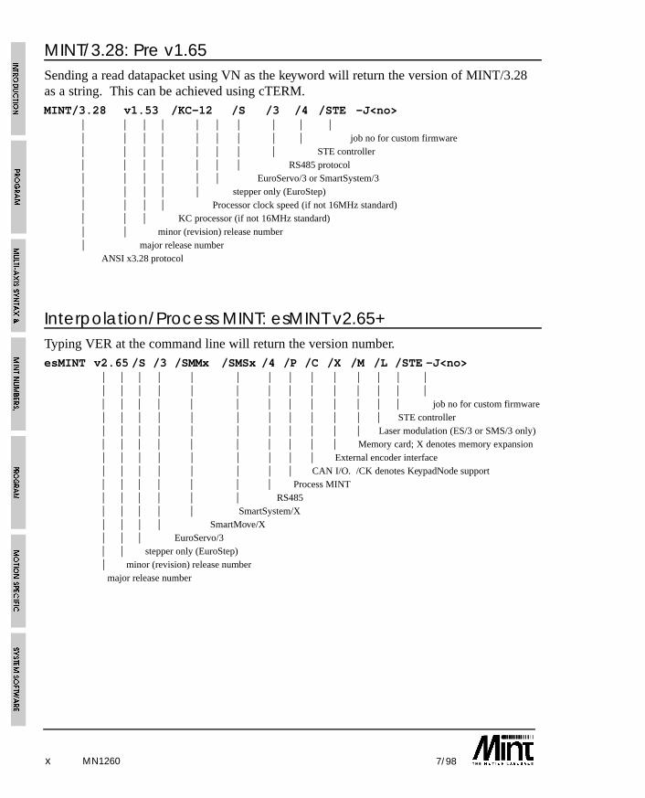
MINT/3.28: Pre v1.65Sending a read datapacket using VN as the keyword will return the version of MINT/3.28as a string. This can be achieved using cTERM. MINT/3.28 v1.53 /KC-12 /S /3 /4 /STE -J<no>
| | | | | | | | | || | | | | | | | | job no for custom firmware| | | | | | | | STE controller| | | | | | | RS485 protocol| | | | | | EuroServo/3 or SmartSystem/3| | | | | stepper only (EuroStep)| | | | Processor clock speed (if not 16MHz standard)| | | KC processor (if not 16MHz standard)| | minor (revision) release number | major release number
ANSI x3.28 protocol
Interpolation/Process MINT: esMINT v2.65+Typing VER at the command line will return the version number.esMINT v2.65 /S /3 /SMMx /SMSx /4 /P /C /X /M /L /STE -J<no>
| | | | | | | | | | | | | || | | | | | | | | | | | | || | | | | | | | | | | | | job no for custom firmware| | | | | | | | | | | | STE controller| | | | | | | | | | | Laser modulation (ES/3 or SMS/3 only)| | | | | | | | | | Memory card; X denotes memory expansion| | | | | | | | | External encoder interface| | | | | | | | CAN I/O. /CK denotes KeypadNode support| | | | | | | Process MINT| | | | | | RS485| | | | | SmartSystem/X| | | | SmartMove/X| | | EuroServo/3 | | stepper only (EuroStep)| minor (revision) release number
major release number
MN1260
xi7/98
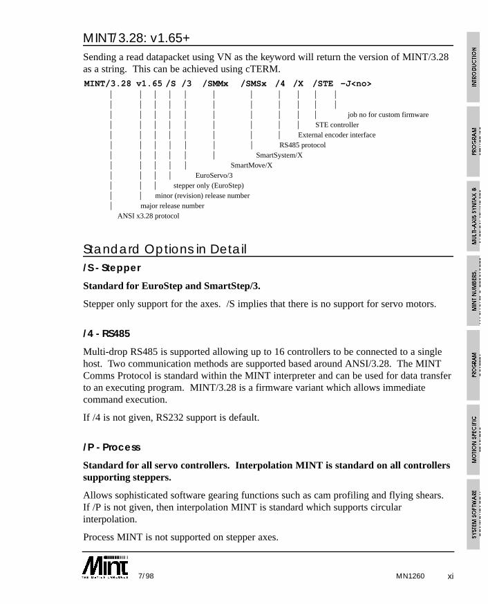
MINT/3.28: v1.65+Sending a read datapacket using VN as the keyword will return the version of MINT/3.28as a string. This can be achieved using cTERM. MINT/3.28 v1.65 /S /3 /SMMx /SMSx /4 /X /STE -J<no>
| | | | | | | | | | || | | | | | | | | | || | | | | | | | | | job no for custom firmware| | | | | | | | | STE controller| | | | | | | | External encoder interface| | | | | | | RS485 protocol| | | | | | SmartSystem/X| | | | | SmartMove/X| | | | EuroServo/3| | | stepper only (EuroStep)| | minor (revision) release number| major release number
ANSI x3.28 protocol
Standard Options in Detail/S - Stepper
Standard for EuroStep and SmartStep/3.
Stepper only support for the axes. /S implies that there is no support for servo motors.
/4 - RS485
Multi-drop RS485 is supported allowing up to 16 controllers to be connected to a singlehost. Two communication methods are supported based around ANSI/3.28. The MINTComms Protocol is standard within the MINT interpreter and can be used for data transferto an executing program. MINT/3.28 is a firmware variant which allows immediatecommand execution.
If /4 is not given, RS232 support is default.
/P - Process
Standard for all servo controllers. Interpolation MINT is standard on all controllerssupporting steppers.
Allows sophisticated software gearing functions such as cam profiling and flying shears.If /P is not given, then interpolation MINT is standard which supports circularinterpolation.
Process MINT is not supported on stepper axes.
MN1260
xii 7/98
/C - CAN
CAN bus I/O supported. This applies only to SmartMove, but when fitted allowsSmartMove to drive the ioNODE range of CAN based I/O devices. /C results in a loss of1000 bytes from the program space reducing it to 26K.
If the CAN keypad (KeypadNode) is supported, this is denoted by a K following the C(/CK).
/X - Three Channel Encoder Interface
Standard for all 2 and 3 axis controllers with the exception of EuroSystem andEuroSystem/STE.
If given, supports the Three Channel Encoder Interface board. This device gives threeadditional encoder input channels which can be used as master references for softwaregearboxes, cam profiling and flying shears.
/M - Memory Card
Standard unless /MX is requested.
Allows the program and configuration file to be stored on battery backed S-RAM,independent of the controller memory. /M also allows array data to be expanded bystoring the arrays on the memory card.
/MX - Memory Expansion
The program and configuration files are stored on an external battery backed memorycard, thus leaving the controller memory free for compiled code and array data. /MXallows larger programs to be written than can be normally supported in the standardonboard RAM.
MN1260
xiii7/98
1. Introduction . . . . . . . . . . . . . . . . . . . . . . . . . . . . . . . . . . . . . . . . . . . . . . . . . . 1-1
1.1 MINT Basics . . . . . . . . . . . . . . . . . . . . . . . . . . . . . . . . . . . . . . . . . . . . . . . 1-5
1.1.1 Program Execution and Termination . . . . . . . . . . . . . . . . . . . . . . . . 1-6
1.2 Safety Features . . . . . . . . . . . . . . . . . . . . . . . . . . . . . . . . . . . . . . . . . . . . . 1-6
1.3 MINT Versions . . . . . . . . . . . . . . . . . . . . . . . . . . . . . . . . . . . . . . . . . . . . . 1-7
1.4 Systems with more than Three Axes (multi-drop) . . . . . . . . . . . . . . . . . . . 1-7
2. Program Structure . . . . . . . . . . . . . . . . . . . . . . . . . . . . . . . . . . . . . . . . . . . 2-1
3. Multi-axis Syntax and Motion K eywords . . . . . . . . . . . . . . . . . . . . . . 3-1
3.1 Motion Commands . . . . . . . . . . . . . . . . . . . . . . . . . . . . . . . . . . . . . . . . . . 3-1
3.2 Motion Variables . . . . . . . . . . . . . . . . . . . . . . . . . . . . . . . . . . . . . . . . . . . . 3-1
3.3 Multi-Axis Syntax . . . . . . . . . . . . . . . . . . . . . . . . . . . . . . . . . . . . . . . . . . . 3-2
3.3.1 Single Axis References using Dot . . . . . . . . . . . . . . . . . . . . . . . . . . 3-5
4. MINT Numbers, Variables and Operators . . . . . . . . . . . . . . . . . . . . . 4-1
4.1 Numbers . . . . . . . . . . . . . . . . . . . . . . . . . . . . . . . . . . . . . . . . . . . . . . . . . . 4-1
4.2 Binary Numbers . . . . . . . . . . . . . . . . . . . . . . . . . . . . . . . . . . . . . . . . . . . . 4-1
4.3 Constants . . . . . . . . . . . . . . . . . . . . . . . . . . . . . . . . . . . . . . . . . . . . . . . . . . 4-2
4.3.1 Pre-defined Constant Keywords . . . . . . . . . . . . . . . . . . . . . . . . . . . 4-3
4.4 Variables . . . . . . . . . . . . . . . . . . . . . . . . . . . . . . . . . . . . . . . . . . . . . . . . . . 4-5
4.4.1 Non-volatile Variables . . . . . . . . . . . . . . . . . . . . . . . . . . . . . . . . . . 4-6
4.5 Arrays . . . . . . . . . . . . . . . . . . . . . . . . . . . . . . . . . . . . . . . . . . . . . . . . . . . . 4-8
4.5.1 Off-line Array Storage . . . . . . . . . . . . . . . . . . . . . . . . . . . . . . . . . . 4-10
4.5.2 Advanced use of Arrays . . . . . . . . . . . . . . . . . . . . . . . . . . . . . . . . . 4-12
4.5.3 Array Data File Format . . . . . . . . . . . . . . . . . . . . . . . . . . . . . . . . . 4-14
4.5.4 Uploading and Downloading Array Data . . . . . . . . . . . . . . . . . . . . 4-17
4.6 Relational and Mathematical Operators . . . . . . . . . . . . . . . . . . . . . . . . . . . 4-20
4.6.1 Performing Bitwise Operations . . . . . . . . . . . . . . . . . . . . . . . . . . . . 4-21
4.6.2 Trigonometric Functions . . . . . . . . . . . . . . . . . . . . . . . . . . . . . . . . 4-22
MN1260
Table of Contents
xiv 7/98
5. Program Control . . . . . . . . . . . . . . . . . . . . . . . . . . . . . . . . . . . . . . . . . . . . . 5-1
5.1 Conditional Statements . . . . . . . . . . . . . . . . . . . . . . . . . . . . . . . . . . . . . . 5-1
5.1.1 IF .. THEN statement . . . . . . . . . . . . . . . . . . . . . . . . . . . . . . . . . . . 5-1
5.1.2 IF block structure . . . . . . . . . . . . . . . . . . . . . . . . . . . . . . . . . . . . . . 5-1
5.1.3 PAUSE statement . . . . . . . . . . . . . . . . . . . . . . . . . . . . . . . . . . . . . . 5-3
5.2 Loops . . . . . . . . . . . . . . . . . . . . . . . . . . . . . . . . . . . . . . . . . . . . . . . . . . . . 5-4
5.2.1 FOR .. NEXT loop . . . . . . . . . . . . . . . . . . . . . . . . . . . . . . . . . . . . . 5-4
5.2.2 REPEAT .. UNTIL loop . . . . . . . . . . . . . . . . . . . . . . . . . . . . . . . . . 5-5
5.2.3 WHILE .. ENDW loop . . . . . . . . . . . . . . . . . . . . . . . . . . . . . . . . . . 5-5
5.2.4 LOOP .. ENDL loop . . . . . . . . . . . . . . . . . . . . . . . . . . . . . . . . . . . 5-6
5.2.5 EXIT statement . . . . . . . . . . . . . . . . . . . . . . . . . . . . . . . . . . . . . . . 5-7
5.2.6 Nesting . . . . . . . . . . . . . . . . . . . . . . . . . . . . . . . . . . . . . . . . . . . . . . 5-7
5.3 Subroutines . . . . . . . . . . . . . . . . . . . . . . . . . . . . . . . . . . . . . . . . . . . . . . . . 5-8
5.3.1 Events & Interrupts . . . . . . . . . . . . . . . . . . . . . . . . . . . . . . . . . . . . 5-9
5.3.1.1 Error Event: #ONERROR . . . . . . . . . . . . . . . . . . . . . . . . 5-10
5.3.1.2 Stop Input Interrupt: #STOP . . . . . . . . . . . . . . . . . . . . . . . 5-10
5.3.2 Digital Input Interrupt: #IN0 .. #IN7 . . . . . . . . . . . . . . . . . . . . . . . . 5-11
5.3.2.1 Position Latch Event: #FASTPOS . . . . . . . . . . . . . . . . . . 5-13
5.4 Terminal Input/Output . . . . . . . . . . . . . . . . . . . . . . . . . . . . . . . . . . . . . . . . 5-14
5.4.1 PRINT Statement . . . . . . . . . . . . . . . . . . . . . . . . . . . . . . . . . . . . . . 5-15
5.4.2 INPUT Statement . . . . . . . . . . . . . . . . . . . . . . . . . . . . . . . . . . . . . . 5-16
5.5 Keypad and Display . . . . . . . . . . . . . . . . . . . . . . . . . . . . . . . . . . . . . . . . . . 5-17
5.5.1 Programming the Keypad and Display . . . . . . . . . . . . . . . . . . . . . . 5-17
5.6 Sending Data to an Executing Program . . . . . . . . . . . . . . . . . . . . . . . . . . . 5-20
5.6.1 Serial Port/Keypad Buffer . . . . . . . . . . . . . . . . . . . . . . . . . . . . . . . 5-20
5.6.2 Reading Data from the Serial Buffer using INKEY . . . . . . . . . . . . 5-21
5.6.3 Host Computer Protected Protocol . . . . . . . . . . . . . . . . . . . . . . . . . 5-23
MN1260
xv7/98
6. Motion Specific Features . . . . . . . . . . . . . . . . . . . . . . . . . . . . . . . . . . . . 6-1
6.1 Torque Control . . . . . . . . . . . . . . . . . . . . . . . . . . . . . . . . . . . . . . . . . . . . . 6-1
6.2 Speed Control . . . . . . . . . . . . . . . . . . . . . . . . . . . . . . . . . . . . . . . . . . . . . . 6-2
6.3 Positional Control . . . . . . . . . . . . . . . . . . . . . . . . . . . . . . . . . . . . . . . . . . . 6-3
6.3.1 Linear Positional Control . . . . . . . . . . . . . . . . . . . . . . . . . . . . . . . . 6-3
6.3.2 Interpolated Moves . . . . . . . . . . . . . . . . . . . . . . . . . . . . . . . . . . . . . 6-5
6.3.3 Linear Interpolation . . . . . . . . . . . . . . . . . . . . . . . . . . . . . . . . . . . . 6-6
6.3.4 Circular Interpolation . . . . . . . . . . . . . . . . . . . . . . . . . . . . . . . . . . . 6-8
6.3.5 Velocity Profile . . . . . . . . . . . . . . . . . . . . . . . . . . . . . . . . . . . . . . . 6-9
6.3.6 Move Buffer and GO . . . . . . . . . . . . . . . . . . . . . . . . . . . . . . . . . . . 6-9
6.3.7 Contoured Moves . . . . . . . . . . . . . . . . . . . . . . . . . . . . . . . . . . . . . . 6-10
6.4 Establishing a Datum . . . . . . . . . . . . . . . . . . . . . . . . . . . . . . . . . . . . . . . . . 6-11
6.4.1 Home Control Word . . . . . . . . . . . . . . . . . . . . . . . . . . . . . . . . . . . . 6-12
6.4.2 Home Sequence . . . . . . . . . . . . . . . . . . . . . . . . . . . . . . . . . . . . . . 6-13
6.4.3 Order of Datuming . . . . . . . . . . . . . . . . . . . . . . . . . . . . . . . . . . . . . 6-14
6.4.4 Defining a New Position . . . . . . . . . . . . . . . . . . . . . . . . . . . . . . . . 6-15
6.5 Pulse Following . . . . . . . . . . . . . . . . . . . . . . . . . . . . . . . . . . . . . . . . . . . . . 6-15
6.6 Encoder Following/Software Gearbox . . . . . . . . . . . . . . . . . . . . . . . . . . . . 6-17
6.6.1 Clutch Distance . . . . . . . . . . . . . . . . . . . . . . . . . . . . . . . . . . . . . . . 6-18
6.6.2 High Resolution Software Gearboxes . . . . . . . . . . . . . . . . . . . . . . . 6-19
6.7 CAM Profiling . . . . . . . . . . . . . . . . . . . . . . . . . . . . . . . . . . . . . . . . . . . . . 6-22
6.7.1.1 Example of Cam Profiling . . . . . . . . . . . . . . . . . . . . . . . . . 6-23
6.7.2 Cam Tables . . . . . . . . . . . . . . . . . . . . . . . . . . . . . . . . . . . . . . . . . . 6-24
6.7.3 Synchronizing Cams with the Fast Interrupt . . . . . . . . . . . . . . . . . . 6-27
6.7.4 Multiple Cam Tables . . . . . . . . . . . . . . . . . . . . . . . . . . . . . . . . . . . 6-27
6.8 Flying Shears . . . . . . . . . . . . . . . . . . . . . . . . . . . . . . . . . . . . . . . . . . . . . . 6-28
6.8.1 Example of a Flying Shear . . . . . . . . . . . . . . . . . . . . . . . . . . . . . . . 6-31
6.9 Triggered Moves . . . . . . . . . . . . . . . . . . . . . . . . . . . . . . . . . . . . . . . . . . . . 6-33
MN1260

xvi 7/98
6.10 Mode of Motion . . . . . . . . . . . . . . . . . . . . . . . . . . . . . . . . . . . . . . . . . . . . 6-34
6.11 Digital Input/Output . . . . . . . . . . . . . . . . . . . . . . . . . . . . . . . . . . . . . . . . . 6-35
6.11.1 Digital Inputs . . . . . . . . . . . . . . . . . . . . . . . . . . . . . . . . . . . . . . . . 6-36
6.11.2 Digital Outputs . . . . . . . . . . . . . . . . . . . . . . . . . . . . . . . . . . . . . . . 6-36
6.12 Analog Inputs . . . . . . . . . . . . . . . . . . . . . . . . . . . . . . . . . . . . . . . . . . . . . 6-37
6.12.1 Joystick Control in MINT/3.28 . . . . . . . . . . . . . . . . . . . . . . . . . . . 6-38
6.13 Input/Output ‘On the Fly’ . . . . . . . . . . . . . . . . . . . . . . . . . . . . . . . . . . . . . 6-41
6.14 The STOP Input . . . . . . . . . . . . . . . . . . . . . . . . . . . . . . . . . . . . . . . . . . . . 6-42
6.15 End of Travel Limit Inputs . . . . . . . . . . . . . . . . . . . . . . . . . . . . . . . . . . . . 6-43
7. System Software Configuration . . . . . . . . . . . . . . . . . . . . . . . . . . . . . . 7-1
7.1 Servo Loop . . . . . . . . . . . . . . . . . . . . . . . . . . . . . . . . . . . . . . . . . . . . . . . 7-2
7.2 Inverter Control . . . . . . . . . . . . . . . . . . . . . . . . . . . . . . . . . . . . . . . . . . . . 7-5
7.3 Positional Resolution and User Units . . . . . . . . . . . . . . . . . . . . . . . . . . . . 7-6
7.4 The Configuration File . . . . . . . . . . . . . . . . . . . . . . . . . . . . . . . . . . . . . . . 7-7
7.5 Data Capture . . . . . . . . . . . . . . . . . . . . . . . . . . . . . . . . . . . . . . . . . . . . . . 7-8
8. Program and Motion Errors . . . . . . . . . . . . . . . . . . . . . . . . . . . . . . . . . . 8-1
8.1 Program Errors . . . . . . . . . . . . . . . . . . . . . . . . . . . . . . . . . . . . . . . . . . . . . 8-3
8.2 Asynchronous Errors . . . . . . . . . . . . . . . . . . . . . . . . . . . . . . . . . . . . . . . . 8-4
8.2.1 Error Handling using ONERROR . . . . . . . . . . . . . . . . . . . . . . . . . 8-5
8.3 Front Panel Status Display . . . . . . . . . . . . . . . . . . . . . . . . . . . . . . . . . . . . 8-7
8.3.1 Error Conditions . . . . . . . . . . . . . . . . . . . . . . . . . . . . . . . . . . . . . . 8-7
8.3.1.1 Output Errors On SmartMove . . . . . . . . . . . . . . . . . . . . . . 8-8
8.3.2 Motion Status Conditions . . . . . . . . . . . . . . . . . . . . . . . . . . . . . . . 8-8
9. MINT Line Editor and Program Buffers . . . . . . . . . . . . . . . . . . . . . . . . 9-1
9.1 Memory Expansion . . . . . . . . . . . . . . . . . . . . . . . . . . . . . . . . . . . . . . . . . 9-2
9.2 Password Protection . . . . . . . . . . . . . . . . . . . . . . . . . . . . . . . . . . . . . . . . . 9-4
9.3 Editor Commands . . . . . . . . . . . . . . . . . . . . . . . . . . . . . . . . . . . . . . . . . . 9-4
10. MINT Keywords . . . . . . . . . . . . . . . . . . . . . . . . . . . . . . . . . . . . . . . . . . . . . 10-1
MN1260
xvii7/98
11. Error Messages . . . . . . . . . . . . . . . . . . . . . . . . . . . . . . . . . . . . . . . . . . . . . 11-1
11.1 General Error Messages . . . . . . . . . . . . . . . . . . . . . . . . . . . . . . . . . . . . 11-1
11.2 Subroutine Errors . . . . . . . . . . . . . . . . . . . . . . . . . . . . . . . . . . . . . . . . . 11-3
11.3 Conditional Statement Errors . . . . . . . . . . . . . . . . . . . . . . . . . . . . . . . . 11-3
11.4 Loop Structure Errors . . . . . . . . . . . . . . . . . . . . . . . . . . . . . . . . . . . . . . 11-4
11.5 Motion Variable/Command Errors . . . . . . . . . . . . . . . . . . . . . . . . . . . . . 11-4
12. MINT Host Computer Communications . . . . . . . . . . . . . . . . . . . . . . 12-1
12.1 Activating Protected Communications . . . . . . . . . . . . . . . . . . . . . . . . . . 12-2
12.2 Use of the COMMS variable . . . . . . . . . . . . . . . . . . . . . . . . . . . . . . . . . 12-3
12.3 Read and Writing Data from a Host . . . . . . . . . . . . . . . . . . . . . . . . . . . 12-4
12.3.1 Writing Data . . . . . . . . . . . . . . . . . . . . . . . . . . . . . . . . . . . . . . . 12-5
12.3.2 Reading Data . . . . . . . . . . . . . . . . . . . . . . . . . . . . . . . . . . . . . . 12-6
12.3.3 Special Location . . . . . . . . . . . . . . . . . . . . . . . . . . . . . . . . . . . . 12-6
12.3.3.1 Aborting Program Execution . . . . . . . . . . . . . . . . . . . . 12-7
12.3.3.2 Program Status . . . . . . . . . . . . . . . . . . . . . . . . . . . . . . 12-7
12.4 Limitations of Use . . . . . . . . . . . . . . . . . . . . . . . . . . . . . . . . . . . . . . . . 12-8
12.5 PC Library Routines . . . . . . . . . . . . . . . . . . . . . . . . . . . . . . . . . . . . . . . 12-8
12.5.1 C Interface . . . . . . . . . . . . . . . . . . . . . . . . . . . . . . . . . . . . . . . . 12-8
12.5.1.1 Reading and Writing Data . . . . . . . . . . . . . . . . . . . . . . 12-9
12.5.2 MS-DOS 5.0 QBasic Interface . . . . . . . . . . . . . . . . . . . . . . . . . 12-10
12.5.2.1 Reading and Writing Data . . . . . . . . . . . . . . . . . . . . . . 12.10
13. MINT/3.28 . . . . . . . . . . . . . . . . . . . . . . . . . . . . . . . . . . . . . . . . . . . . . . . . . 13-1
13.1 Serial Port Configuration . . . . . . . . . . . . . . . . . . . . . . . . . . . . . . . . . . . . 13-1
13.2 Data Packet Structure . . . . . . . . . . . . . . . . . . . . . . . . . . . . . . . . . . . . . . 13-2
13.2.1 Reset: EOT . . . . . . . . . . . . . . . . . . . . . . . . . . . . . . . . . . . . . . . . 13-2
13.2.2 Drive ID . . . . . . . . . . . . . . . . . . . . . . . . . . . . . . . . . . . . . . . . . . 13-2
13.2.3 MINT Keyword . . . . . . . . . . . . . . . . . . . . . . . . . . . . . . . . . . . . . 13-3
13.2.4 Data . . . . . . . . . . . . . . . . . . . . . . . . . . . . . . . . . . . . . . . . . . . . . 13-3
MN1260
xviii 7/98
13.2.5 End of Data: ETX, ENQ . . . . . . . . . . . . . . . . . . . . . . . . . . . . . 13-4
13.2.6 Checksum . . . . . . . . . . . . . . . . . . . . . . . . . . . . . . . . . . . . . . . . 13-4
13.3 Slave Reply . . . . . . . . . . . . . . . . . . . . . . . . . . . . . . . . . . . . . . . . . . . . . . 13-5
13.3.1 MINT/3.28 Error Codes . . . . . . . . . . . . . . . . . . . . . . . . . . . . . 13-5
13.4 Writing Data . . . . . . . . . . . . . . . . . . . . . . . . . . . . . . . . . . . . . . . . . . . . . 13-6
13.5 Reading Data . . . . . . . . . . . . . . . . . . . . . . . . . . . . . . . . . . . . . . . . . . . . 13-6
13.6 Commands . . . . . . . . . . . . . . . . . . . . . . . . . . . . . . . . . . . . . . . . . . . . . . 13-7
13.7 Buffered Motion Commands . . . . . . . . . . . . . . . . . . . . . . . . . . . . . . . . . 13-8
13.7.1 The GO Command . . . . . . . . . . . . . . . . . . . . . . . . . . . . . . . . . 13-8
13.8 MINT/3.28 Example . . . . . . . . . . . . . . . . . . . . . . . . . . . . . . . . . . . . . . . 13-9
13.9 MINT/3.28 Supported Keywords . . . . . . . . . . . . . . . . . . . . . . . . . . . . . 13-10
13.10 MINT/3.28 C Library Routine for Host Computer . . . . . . . . . . . . . . . . . 13-11
13.10.1 Writing Data . . . . . . . . . . . . . . . . . . . . . . . . . . . . . . . . . . . . . . 13-11
13.10.2 Reading Data . . . . . . . . . . . . . . . . . . . . . . . . . . . . . . . . . . . . . 13-12
13.10.3 Issuing a Command . . . . . . . . . . . . . . . . . . . . . . . . . . . . . . . . 13-13
14. MINT Execution Speed . . . . . . . . . . . . . . . . . . . . . . . . . . . . . . . . . . . . . . 14-1
14.1 Improving Execution Speed . . . . . . . . . . . . . . . . . . . . . . . . . . . . . . . . . 14-2
14.1.1 Unnecessary use of Square Brackets . . . . . . . . . . . . . . . . . . . . 14-2
14.1.2 Optimizing Logical Expressions . . . . . . . . . . . . . . . . . . . . . . . 14-3
14.1.3 Removing Blank Lines . . . . . . . . . . . . . . . . . . . . . . . . . . . . . . 14-4
14.1.4 Performing More Time Intensive Code Outside to Dead Time . 14-4
14.1.5 Turning Redundant Axes Off . . . . . . . . . . . . . . . . . . . . . . . . . 14-5
14.1.6 Replacing Single Axis Reference with Dot . . . . . . . . . . . . . . . 14-5
15. Manuals and Software for MINT Products . . . . . . . . . . . . . . . . . . . . 15-1
MN1260
1-17/98
1. IntroductionMINT™, is a structured form of Basic, custom designed for motion control applications,either stepper or servo. MINT™ has been written to allow users to very quickly get upand running with simple motion programs, while providing a wide range of more powerfulcommands for complex applications. MINT’s built in line editor allows programs to bedeveloped on the target by simply connecting a terminal to your controller. cTERM(available for both DOS and Windows™), a terminal emulator specially configured for thecontroller for use on a PC is provided with each control system.
As well as supporting a Basic like structure, MINT has a number of motion specifickeywords built in. These keywords allow control of motor position, speed, torque,interpolation and synchronization of multiple axes. You also have full software controlover the basic motor control parameters such as servo loop gains.
Applications can vary from simple single axis positional control, to a multi-axis systemwith 48 axes of motion controlled by a host computer over an RS485 multi-drop link.Between these two extremes, MINT’s flexible and powerful command set will provide asolution to the vast majority of industrial motion control applications.
MINT has the following features:
• Support for 3 axis of control on one card
• Support for both servo and stepper motors
• Basic constructs such as IF THEN, FOR NEXT and subroutines
• User variables as with Basic. Variables can be given any meaningful name up to 10characters in length
• Subroutines that are referenced with a label rather a line number. The label can begiven any valid name
• Extensive support for serial and LCD display I/O
• Interrupts on inputs
• Array variables. Size limited only by available memory
• Error recovery from limits, following errors or external errors
• Circular and linear interpolation
• Cam profiling and Flying Shears
• Pulse and encoder following
• Protected communications protocol over a multi-drop RS485 link
MN1260
1-2 7/98
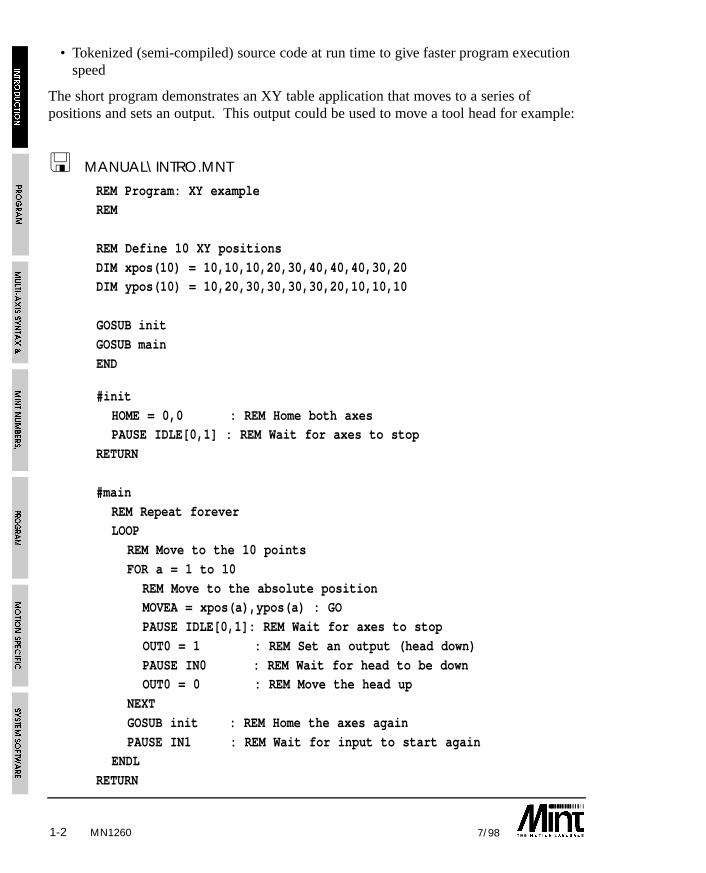
• Tokenized (semi-compiled) source code at run time to give faster program executionspeed
The short program demonstrates an XY table application that moves to a series ofpositions and sets an output. This output could be used to move a tool head for example:
< MANUAL\INTRO.MNT
REM Program: XY exampleREM
REM Define 10 XY positions
DIM xpos(10) = 10,10,10,20,30,40,40,40,30,20DIM ypos(10) = 10,20,30,30,30,30,20,10,10,10
GOSUB init
GOSUB main
END
#init
HOME = 0,0 : REM Home both axesPAUSE IDLE[0,1] : REM Wait for axes to stop
RETURN
#main
REM Repeat foreverLOOP
REM Move to the 10 points
FOR a = 1 to 10
REM Move to the absolute positionMOVEA = xpos(a),ypos(a) : GO
PAUSE IDLE[0,1]: REM Wait for axes to stop
OUT0 = 1 : REM Set an output (head down)
PAUSE IN0 : REM Wait for head to be downOUT0 = 0 : REM Move the head up
NEXT
GOSUB init : REM Home the axes again
PAUSE IN1 : REM Wait for input to start againENDL
RETURN
MN1260
1-37/98
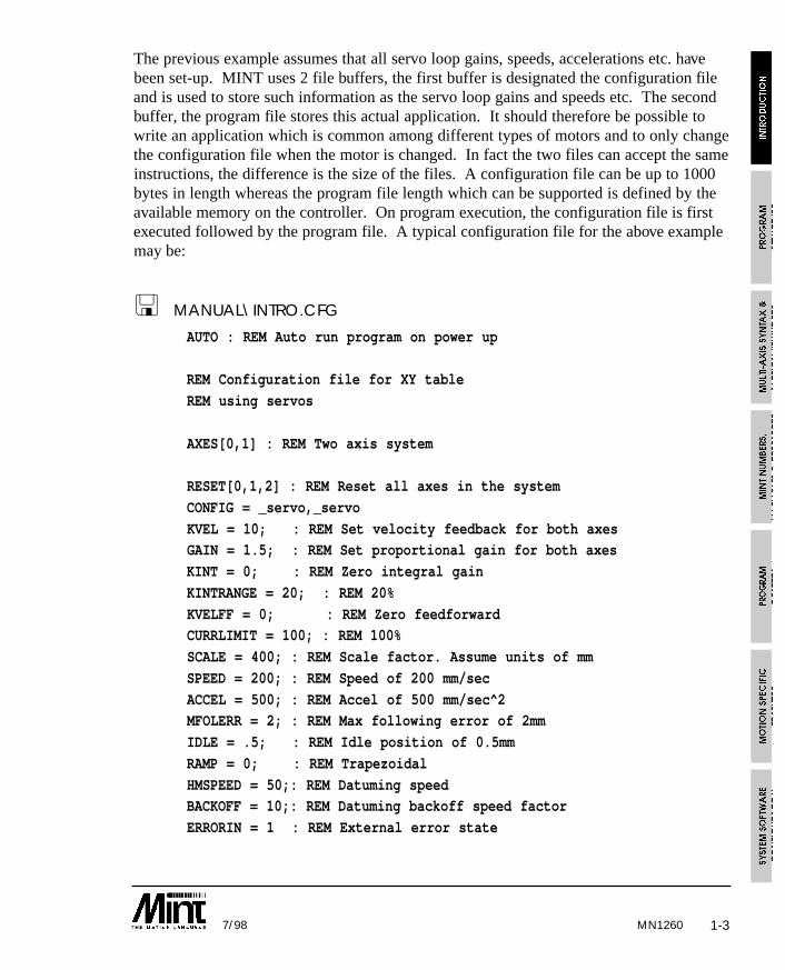
The previous example assumes that all servo loop gains, speeds, accelerations etc. havebeen set-up. MINT uses 2 file buffers, the first buffer is designated the configuration fileand is used to store such information as the servo loop gains and speeds etc. The secondbuffer, the program file stores this actual application. It should therefore be possible towrite an application which is common among different types of motors and to only changethe configuration file when the motor is changed. In fact the two files can accept the sameinstructions, the difference is the size of the files. A configuration file can be up to 1000bytes in length whereas the program file length which can be supported is defined by theavailable memory on the controller. On program execution, the configuration file is firstexecuted followed by the program file. A typical configuration file for the above examplemay be:
< MANUAL\INTRO.CFG
AUTO : REM Auto run program on power up
REM Configuration file for XY table
REM using servos
AXES[0,1] : REM Two axis system
RESET[0,1,2] : REM Reset all axes in the system
CONFIG = _servo,_servo
KVEL = 10; : REM Set velocity feedback for both axesGAIN = 1.5; : REM Set proportional gain for both axes
KINT = 0; : REM Zero integral gain
KINTRANGE = 20; : REM 20%
KVELFF = 0; : REM Zero feedforwardCURRLIMIT = 100; : REM 100%
SCALE = 400; : REM Scale factor. Assume units of mm
SPEED = 200; : REM Speed of 200 mm/sec
ACCEL = 500; : REM Accel of 500 mm/sec^2MFOLERR = 2; : REM Max following error of 2mm
IDLE = .5; : REM Idle position of 0.5mm
RAMP = 0; : REM Trapezoidal
HMSPEED = 50;: REM Datuming speed BACKOFF = 10;: REM Datuming backoff speed factor
ERRORIN = 1 : REM External error state
MN1260
1-4 7/98
The keyword, AUTO, at the top of the configuration file is used to instruct the controllerto automatically run the configuration, then the program file on power-up. AUTO must bethe first command in the configuration otherwise you will be taken to the command line.The command line allows commands to be entered for immediate execution. To execute aprogram without AUTO, the RUN command would be typed in at the command line. Toterminate an executing program, is used from the terminal.
You will note in the example, such keywords as RESET, KVEL and SPEED etc. Theseare motion specific keywords and are used to access motion control and input/outputfeatures of the system. All motion keywords, unlike the BASIC type keywords (forexample: FOR, PRINT, WHILE), can be abbreviated to two letters. For instance, SPEEDis abbreviated to SP which is useful for saving file space.
To access a particular axis, square brackets are used next to the motion keyword. Forexample:
SPEED[1] = 10
or a dot as shown:
SPEED.1 = 10
will set the speed of axis 1 to 10 units where axes are referenced as 0, 1 and 2.
ACCEL[0,1] = 600,800
will set the acceleration of axis 0 to 600 units and axis 1 to 800 units.
a = POS[2]
will assign the position of axis 2 to the user variable a.
In most cases the square brackets are optional.
SPEED[0,1] = 10,20
SPEED = 10,20
are the same depending on the value of the default axes string as defined by the AXESkeyword. The AXES keyword as seen in the configuration file example (of AXES[0,1])tells MINT that all motion keywords relate to 2 axes, i.e. 0 and 1 unless explicitlyindicated by enclosing the axes in square brackets after the keyword. For example:
RESET[0,1,2]as used in the configuration file example will reset various parameters and error flags to aknown state on axes 0,1 and 2.
Multi-axis syntax and the AXES keyword is explained in greater detail in section 3.
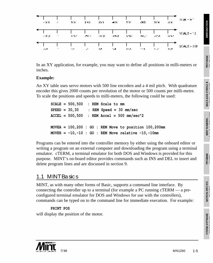
MINT by default defines all positional and speed related motion keywords in terms ofencoder quadrature counts for servo motors or steps for stepper motors. Using theSCALE keyword, these keywords can be scaled to your own units to suit your application.The diagram below shows the effect of scaling on positional information:
MN1260
1-57/98
In an XY application, for example, you may want to define all positions in milli-meters orinches.
Example:
An XY table uses servo motors with 500 line encoders and a 4 mil pitch. With quadratureencoder this gives 2000 counts per revolution of the motor or 500 counts per milli-metre.To scale the positions and speeds to milli-meters, the following could be used:
SCALE = 500,500 : REM Scale to mm
SPEED = 30,30 : REM Speed = 30 mm/sec
ACCEL = 500,500 : REM Accel = 500 mm/sec^2
MOVEA = 100,200 : GO : REM Move to position 100,200mm
MOVER = -10,-10 : GO : REM Move relative -10,-10mm
Programs can be entered into the controller memory by either using the onboard editor orwriting a program on an external computer and downloading the program using a terminalemulator. cTERM, a terminal emulator for both DOS and Windows is provided for thispurpose. MINT’s on-board editor provides commands such as INS and DEL to insert anddelete program lines and are discussed in section 9.
1.1 MINT BasicsMINT, as with many other forms of Basic, supports a command line interface. Byconnecting the controller up to a terminal (for example a PC running cTERM — a pre-configured terminal emulator for DOS and Windows for use with the controllers),commands can be typed on to the command line for immediate execution. For example:
PRINT POS
will display the position of the motor.
MN1260
1-6 7/98
Multiple commands can also be entered by separating the commands with colon (:). Forexample:
MOVEA = 100 : GO : PAUSE IDLE : OUT1 = 1
will move the motor to position 100, wait for it to come to rest and then set output bit 1.
Some commands, such as DIM, COMMSON, COMMSOFF, GOSUB and GOTO cannotbe executed from the command line.
1.1.1 Program Execution and Termination
A program (series of commands) can be created using either an offline editor or the MINTline editor (See section 9 for details on the editor and editor commands). A program, onceentered into the controller can be executed using the RUN command. Alternatively, thecommand AUTO allows the program to be executed automatically on power up.
Once a program is running execution can be terminated by sending Ctrl-E (character 05H)down the serial port. This will terminate program execution and MINT will return withthe message:
Break at line XXX
From the command line, it is possible to execute a continuous loop. In the same way asprogram execution is terminated, Ctrl-E is used to terminate command line execution. Forexample:
LOOP : ? IN : ENDL
If the MINT Comms Protocol is running, Ctrl-E will have no effect. The MINTComms Protocol must be terminated first. See section 12.3.3.1 for details.
1.2 Safety FeaturesBoth the controller card and MINT incorporate a number of safety features. These are:
• End of travel limits resulting in a limit error.
• The setting of a maximum permissible following error (MFOLERR) before cuttingpower to the motors. This is very useful if an axis hits an endstop where the followingerror can build up.
• Stop input to bring all axes to a controlled stop.
• External error input to bring all axes to a crash stop.
MINT has full control over these features, should an error occur, an ONERROR routinewill be called. From the ONERROR routine you can decide to recover from the error orperform a complete system shut-down for example.
MN1260
1-77/98
1.3 MINT VersionsMINT is available in 3 versions:
Process MINT Process MINT, incorporates such motion control features assoftware gearboxes, cam profiles and flying shears. ProcessMINT supports up to 3 axes of linear interpolation but does notsupport circular interpolation.
Is must be noted that Process MINT supports cam profiles andflying shears on the first 2 axes only (Axes 0 and 1).
Interpolation MINT Interpolation MINT provides full linear and circularinterpolation within the MINT environment. InterpolationMINT does not support the cam profiling and flying shearcapabilities of Process MINT. A subset of Process MINT’ssoftware gearboxes are supported.
MINT/3.28 MINT/3.28 is intended specifically for systems where a hostcomputer sends motion control commands to the controller inreal time. Motion control programs are not supported on thecontroller, but commands are sent by a host computer by meansof datapackets.
MINT/3.28 only supports a subset of the MINT command set,namely the motion control commands. The Process MINTcommand set is not supported.
MINT/3.28 will operate over either an RS232 or RS485 link.The physical constraints of RS232 allow only point-to-pointcommunication, i.e. one host computer can talk to onecontroller, RS485 provides longer transmission distances andallows a single host computer to communicate with up to 16controllers on one multi-drop link.
Within a multi-drop 485 system using MINT/3.28, a controllercannot act as a host to other controllers on the system.
1.4 Systems with more than Three Axes (multi-drop)MINT only supports the control of 3 axes on one controller. However, using a hostcomputer based system it is possible to connect up to 16 controllers on to a multi-dropRS485 serial link and to issue instructions to these controllers using specially constructeddata packets.
MN1260
1-8 7/98
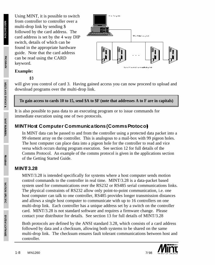
Using MINT, it is possible to switchfrom controller to controller over amulti-drop link by sending $followed by the card address. Thecard address is set by the 4 way DIPswitch, details of which can befound in the appropriate hardwareguide. Note that the card addresscan be read using the CARDkeyword.
Example:
$3
will give you control of card 3. Having gained access you can now proceed to upload anddownload programs over the multi-drop link.
To gain access to cards 10 to 15, send $A to $F (note that addresses A to F are in capitals)
It is also possible to pass data to an executing program or to issue commands forimmediate execution using one of two protocols.
MINT Host Computer Communications (Comms Protocol)In MINT data can be passed to and from the controller using a protected data packet into a99 element array on the controller. This is analogous to a mail-box with 99 pigeon holes.The host computer can place data into a pigeon hole for the controller to read and viceversa which occurs during program execution. See section 12 for full details of theComms Protocol. An example of the comms protocol is given in the applications sectionof the Getting Started Guide.
MINT/3.28MINT/3.28 is intended specifically for systems where a host computer sends motioncontrol commands to the controller in real time. MINT/3.28 is a data-packet basedsystem used for communications over the RS232 or RS485 serial communications links.The physical constraints of RS232 allow only point-to-point communication, i.e. onehost computer can talk to one controller, RS485 provides longer transmission distancesand allows a single host computer to communicate with up to 16 controllers on onemulti-drop link. Each controller has a unique address set by a switch on the controllercard. MINT/3.28 is not standard software and requires a firmware change. Pleasecontact your distributor for details. See section 13 for full details of MINT/3.28
Both protocols are defined by the ANSI standard 3.28, which consists of a card addressfollowed by data and a checksum, allowing both systems to be shared on the samemulti-drop link. The checksum ensures fault tolerant communications between host andcontroller.
MN1260
2-17/98
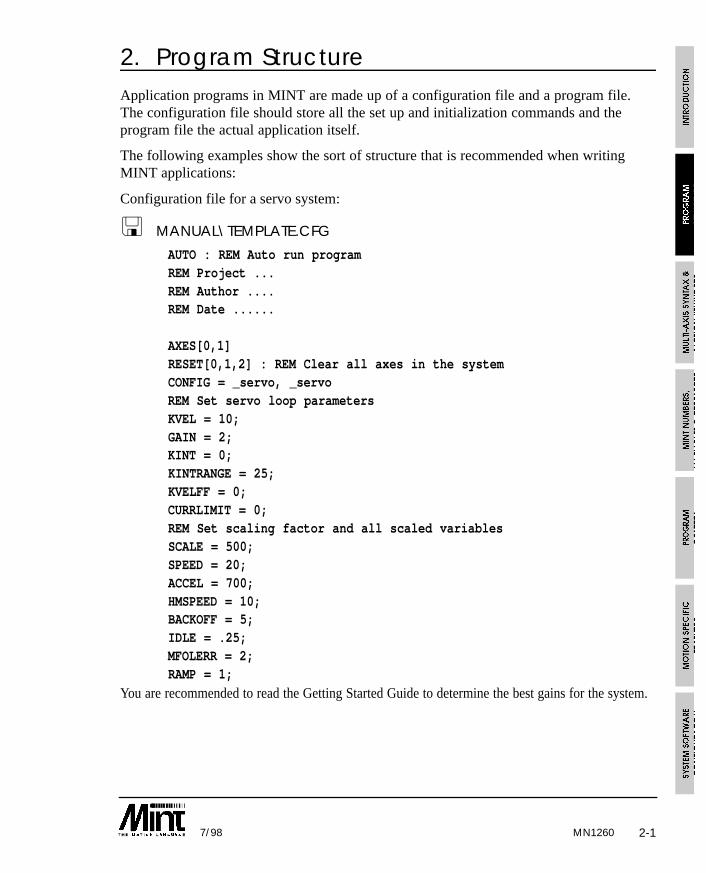
2. Program StructureApplication programs in MINT are made up of a configuration file and a program file.The configuration file should store all the set up and initialization commands and theprogram file the actual application itself.
The following examples show the sort of structure that is recommended when writingMINT applications:
Configuration file for a servo system:
< MANUAL\TEMPLATE.CFG
AUTO : REM Auto run programREM Project ...REM Author ....REM Date ......
AXES[0,1]RESET[0,1,2] : REM Clear all axes in the systemCONFIG = _servo, _servoREM Set servo loop parametersKVEL = 10;GAIN = 2;KINT = 0;KINTRANGE = 25;KVELFF = 0;CURRLIMIT = 0;REM Set scaling factor and all scaled variablesSCALE = 500;SPEED = 20;ACCEL = 700;HMSPEED = 10;BACKOFF = 5;IDLE = .25;MFOLERR = 2;RAMP = 1;
You are recommended to read the Getting Started Guide to determine the best gains for the system.
MN1260
2-2 7/98
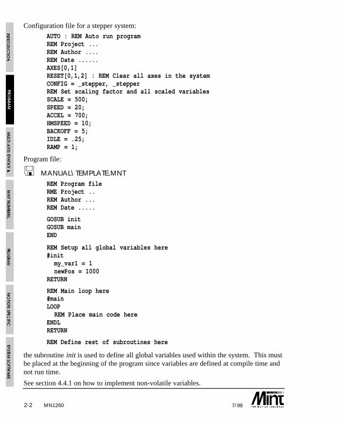
Configuration file for a stepper system:
AUTO : REM Auto run programREM Project ...REM Author ....REM Date ......AXES[0,1]RESET[0,1,2] : REM Clear all axes in the systemCONFIG = _stepper, _stepperREM Set scaling factor and all scaled variablesSCALE = 500;SPEED = 20;ACCEL = 700;HMSPEED = 10;BACKOFF = 5;IDLE = .25;RAMP = 1;
Program file:
< MANUAL\TEMPLATE.MNTREM Program fileRME Project ..REM Author ...REM Date .....
GOSUB initGOSUB mainEND
REM Setup all global variables here#init
my_var1 = 1newPos = 1000
RETURN
REM Main loop here#mainLOOP
REM Place main code hereENDLRETURN
REM Define rest of subroutines here
the subroutine init is used to define all global variables used within the system. This mustbe placed at the beginning of the program since variables are defined at compile time andnot run time.
See section 4.4.1 on how to implement non-volatile variables.
MN1260
MN1260 3-17/98
3. Multi-axis Syntax and Motion KeywordsMotion keywords can be broken down into 2 groups:
1. Motion commands
2. Motion variables
3.1 Motion CommandsMotion commands are used very much like a Basic command such as PRINT. Forexample:
STOP
will bring the axes to a controlled stop.
GO[0,1]
will begin motion on axes 0 and 1. Note the use of square brackets to reference axes.This is explained in detail later on.
3.2 Motion VariablesA motion variable is used very much like a user or Basic type variable in that it can bewritten to or read from. For example:
GAIN = 1 : REM Set the proportional gainPRINT POS : REM Print the current position
Some motion variables are read only and some are write only. For example:
a = OUT1
is invalid since OUT1 is a write only variable that is used to set the value of digital outputbit 1.
VEL = 0is invalid since VEL is a read only variable that returns the instantaneous velocity of themotor.
Motion variables are range checked when written to. For example:
SCALE = -1
will display the error message “ERROR: Out of range” (if a terminal is connected)because SCALE only accepts a value between 1 and 65000.
Square brackets are used to reference axes as for motion commands. For example:
SPEED[1,2] = 10,20
MN12603-2 7/98
set the speed of axis 1 to 10 units and axis 2 to 20 units. Multi-axis syntax is explained indetail in the next section.
3.3 Multi-Axis SyntaxWith the exception of a few motion keywords, motion keywords are axis related in thatsetting the speed, for example, on one axis has no effect on the speed of the other axes.MINT’s multi-axis syntax supports up to 3 axes on one controller.
MINT uses the convention of axis number 0 to refer to the first axis, axis number 1 torefer to the second axis and so on.
In a single axis system, you do not have to specify the axis number explicitly since MINTwill default to axis 0 (the first axis in the system). Therefore:
GAIN = 1will set the proportional gain on axis 0 to 1.
In a multi-axis system, each axis is referenced by enclosing the axis numbers in squarebrackets [] immediately after the motion keyword. For example, to set the speed of axis 0and 1 to 10 and 30 respectively:
SPEED[0,1] = 10,30
or:
SPEED[1,0] = 30,10
The number of parameters following the equal sign cannot be greater than the number ofaxes given except in a few cases (see CIRCLEA and CIRCLER). The following isinvalid:
MOVEA[0,1] = 100,150,500where MOVEA is used to set-up an absolute positional move. However:
MOVEA[0,1,2] = 10,20
is valid and will set-up an absolute move on axis 0 and 1 only of 10 and 20 unitsrespectively.
Variables can be used as axis numbers:
MOVER[a] = 100
is valid provided a is in the range of 0 <= a <= 2.
MOVER[a+1] = 100
is invalid. The expression “a+1” must be assigned to a variable before being passed as anaxis number.
MN1260 3-37/98
The keyword AXES is used to set-up a default axis string. For example:
AXES[0,1]
SCALE = 10,10SPEED = 200,300
ACCEL = 500,500
is the same as:
SCALE[0,1] = 10,10SPEED[0,1] = 200,300
ACCEL[0,1] = 500,500
Not only does the AXES keyword save on typing, but it also speeds up program execution.To see the current status of the AXES keyword, type AXES at the command line. AXESon its own in a program will result in a run time error.
When the controller is first powered up, the AXES keyword will default to the axes 0, 1and 2 (for a 3 axis controller) i.e.:
AXES[0,1,2]With the AXES string set, MINT will apply the following rules: Assuming AXES[0,1]
Example 1: Motion Commands
STOP
will perform a controlled stop on axes 0 and 1 and is equivalent to
STOP[0,1]
Example 2: Writing to Motion Variables
SPEED = 10
will set the speed of axis 0 to 10 and is equivalent to:
SPEED[0] = 10
Example 3: Reading Motion Variables
a = POS
will read the instantaneous position of axis 0 and is equivalent to:
a = POS[0]
With the AXES keyword set a single axis can still be referenced. For example, assumingAXES[0,1,2]:
SPEED = 10
will set the speed of axis 0 to 10
MN12603-4 7/98
SPEED = ,10will set the speed of axis 1 to 10
SPEED = ,,20
will set the speed of axis 2 to 10.
In some cases, the values assigned to each axis are the same. For example in a servosystem with identical amplifiers and motors, the servo gains will no doubt be the same.Instead of writing the following:
AXES[0,1,2]
KVEL = 10,10,10GAIN = 1.5,1.5,1.5
KINT = .1,.1,.1
you can write
AXES[0,1,2]KVEL = 10;
GAIN = 1.5;
KINT = .1;
The semicolon will apply the last value to all the remaining axes. For example:
SPEED[0,1,2] = 10,20;
will set the speed of axis 0 to 10 and the speed of axis 1 and 2 to 20 and 20.
It is possible to read more than 1 axis using the square bracket notation. For example:
PAUSE IDLE[0,1]
will wait for both axis 0 and axis 1 to come to a stop. This is equivalent to:
PAUSE IDLE[0] AND IDLE[1]but the first expression is both quicker to execute and takes up less code space. However:
PAUSE IDLE
will only wait for the first axis set by the AXES keyword to become idle. If we assumeAXES[0,1] has been set, then this is equivalent to:
PAUSE IDLE[0]
Where more than one axis is read, the results are ANDed together using bitwisearithmetic. This is only really useful for keywords that return true (1) or false (0).
3-57/98 MN1260
3.3.1 Single Axis References using Dot
A single axis can be reference using dot ‘.’, followed by the axis number. The axisnumber can be expressed as either a number or a variable. For example:
b = POS.1
is the same as:
b = POS[1]
The first expression has 2 advantage over the second. First, it occupies less code space,and secondly, it executes some 50% quicker.
Note that:
b = POS.a + 1is equivalent to:
b = POS[a] + 1

3-6 7/98MN1260
MN1260 4-17/98
4. MINT Numbers, Variables and Operators
4.1 Numbers
All numbers are represented as a four byte scaled integer. This gives a range of +/-8,388,607.996, where the fractional part has a resolution of one part in 256 or 0.004. Dueto the integer nature of the processor, numbers in MINT are not true floating pointnumbers since this would result in slower program execution. In a linear table application,MINT numbers would give a maximum positional resolution of 1 micron in 16 meters.
Example:
PRINT 1.002will display
1.003
to the terminal. This is because MINT will round the number to the nearest part in 256.The fractional part of a MINT number is calculated as follows:
Given a number of 1.15, what proportion of 256 is the fractional part 0.15 ?
Assuming 3 fractional places, 0.15 can be represented by 150/1000, the internal value of0.15 is given by:
INT( 150 * 256 / 1000 ) = 38
therefore 0.15 is represented as 38/256 or 0.148 (approx.). In fact the statement “PRINT0.15” will display “0.148” to the terminal screen.
4.2 Binary Numbers
Binary numbers are defined by placing a zero before the binary string. For example:
PRINT 011011
will display
27
Binary numbers are useful when writing to outputs. For example:
OUT = 011110000
this will turn the top 4 bits on and the bottom 4 bits off.
a = 11
is not a valid binary number and will assign the value of 11 to the variable a.
a = 05
MN12604-2 7/98
is an invalid binary number and will generate a syntax error, however:
a = 0.5
is acceptable and will define the value of 0.5 to the variable a.
4.3 Constants
A constant is a number in your program that does not change during program execution.For instance, the expression:
SPEED = 20.5assigns the constant value 20.5 to the motion variable SPEED.
MINT accepts four types of constants:
• Constant numbers
• Binary constants
• Character constants
• Pre-defined constant keywords
By default, MINT interprets all constant numbers as decimal unless otherwise specified.Binary constants are defined by prefixing the number with a zero, as discussed in theprevious section.
MINT also provides character constants for use with the INKEY and READKEYcommands. To define a character constant, enclose the character in single quotes, forexample:
a = ‘A’
will assign the value of 65 to a. MINT will convert all character constants to their uppercase equivalent. Therefore:
‘A’
‘a’
both have the value of 65.
Refer to an ASCII character table for the decimal value of each character.
MN1260 4-37/98
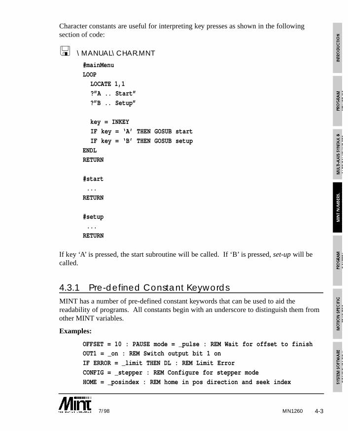
Character constants are useful for interpreting key presses as shown in the followingsection of code:
< \MANUAL\CHAR.MNT
#mainMenu
LOOPLOCATE 1,1
?”A .. Start”
?”B .. Setup”
key = INKEY
IF key = ‘A’ THEN GOSUB start
IF key = ‘B’ THEN GOSUB setup
ENDLRETURN
#start
...RETURN
#setup
...RETURN
If key ‘A’ is pressed, the start subroutine will be called. If ‘B’ is pressed, set-up will becalled.
4.3.1 Pre-defined Constant KeywordsMINT has a number of pre-defined constant keywords that can be used to aid thereadability of programs. All constants begin with an underscore to distinguish them fromother MINT variables.
Examples:
OFFSET = 10 : PAUSE mode = _pulse : REM Wait for offset to finishOUT1 = _on : REM Switch output bit 1 on
IF ERROR = _limit THEN DL : REM Limit Error
CONFIG = _stepper : REM Configure for stepper mode
HOME = _posindex : REM home in pos direction and seek index
MN12604-4 7/98
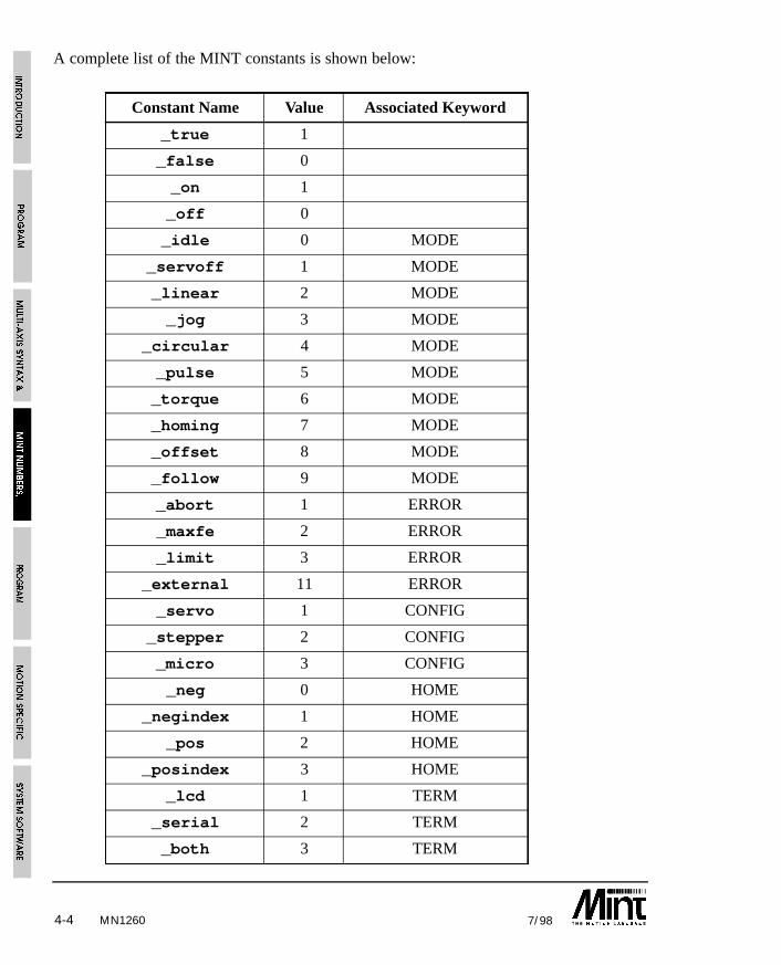
A complete list of the MINT constants is shown below:
Constant Name Value Associated Keyword
_true 1
_false 0
_on 1
_off 0
_idle 0 MODE
_servoff 1 MODE
_linear 2 MODE
_jog 3 MODE
_circular 4 MODE
_pulse 5 MODE
_torque 6 MODE
_homing 7 MODE
_offset 8 MODE
_follow 9 MODE
_abort 1 ERROR
_maxfe 2 ERROR
_limit 3 ERROR
_external 11 ERROR
_servo 1 CONFIG
_stepper 2 CONFIG
_micro 3 CONFIG
_neg 0 HOME
_negindex 1 HOME
_pos 2 HOME
_posindex 3 HOME
_lcd 1 TERM
_serial 2 TERM
_both 3 TERM
MN1260 4-57/98
4.4 VariablesVariables are meaningful names that are used to represent data in a program. You canassign a value to a variable at the beginning of a program and use it like a constant, or itsvalue may be set as the result of calculations or incremented in a loop. These variablesare referred to as user variables to distinguish them from motion variables which arereserved keywords in MINT used to perform a specific task.
User variables can have any name as long as it is not a reserved word or MINT keywordand begins with a letter followed by any alphanumeric character or an underscore.Alternatively, variable names can begin with an underscore as long as it is followed by analphanumeric. Variable names may be any length but only the first ten characters aresignificant.
Examples of variable names:
my_var1
xPosition
_myVar2Unlike many implementations of BASIC, variables must be declared before being used,otherwise an error is generated. A variable declaration is any valid assignment to thevariable. For example:
aVar = 10
bVar = aVar
will define variables aVar and bVar if they are not already defined and give them a valueof 10.
It should also be noted that the following statements will also define a variable:
FOR .. NEXT
DIM
INPUT
Variables can be used in any valid expression. For example:
newPos = 2oldPos = newPos*2
PRINT oldPos+newPos
Running this code fragment will define variables oldPos and newPos and print the value 6to the screen.
An extensive range of operators can be used on numbers and variables. These arediscussed in more detail in a later section.
MN12604-6 7/98
MINT only supports numeric variables, string variables foundin standard Basic are not implemented.
There are two MINT commands associated with user variables. DISPLAY lists allcurrently defined variables and their values. RELEASE erases the currently definedvariables from memory.
A maximum of 501 variable names can be defined in any one program.To clear all variables from memory, use RELEASE. Note that RELEASE
cannot be used in a program. If you wish to clear all variables beforeexecuting a program each time, place RELEASE in the configuration file,
ensuring that no variables are defined in the configuration file.
Motion variables have an almost identical syntax to user variable assignment and can beused in a similar way:
c = POS * 10
will assign the position of the axis, multiplied by 10, to the variable c.
4.4.1 Non-volatile Variables
Array data is by default non-volatile but variables are not since they must first be declaredby assigning a value to them which makes them volatile (ie their value at power down isnot retained). For example:
my_var1 = 0
my_var2 = 0
will assign both my_var1 and my_var2 to zero. Due to the way MINT compiles andexecutes programs, non-volatile variables can be set-up by assigning them in a subroutine,but never calling the routine. For example:
#non_volatile
my_var1 = 0my_var2 = 0
RETURN
MINT code is compiled before it is executed. It is at this stage that variables are definedin the symbol table. If the variable already exists in the table, its value is preserved. If thevariable does not exist, (i.e. has just been defined due to a change in the program), it isassigned in the table with a value of 0.
1The memory card expansion option allows a maximum of 100 variables to be defined.
MN1260 4-77/98
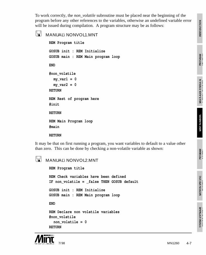
To work correctly, the non_volatile subroutine must be placed near the beginning of theprogram before any other references to the variables, otherwise an undefined variable errorwill be issued during compilation. A program structure may be as follows:
< MANUAL\NONVOL1.MNT
REM Program title
GOSUB init : REM InitializeGOSUB main : REM Main program loop
END
#non_volatilemy_var1 = 0
my_var2 = 0
RETURN
REM Rest of program here
#init
RETURN
REM Main Program loop
#main
RETURN
It may be that on first running a program, you want variables to default to a value otherthan zero. This can be done by checking a non-volatile variable as shown:
< MANUAL\NONVOL2.MNT
REM Program title
REM Check variables have been definedIF non_volatile = _false THEN GOSUB default
GOSUB init : REM InitializeGOSUB main : REM Main program loop
END
REM Declare non volatile variables#non_volatile
non_volatile = 0RETURN
MN12604-8 7/98
REM Declare variable and initialize them#default
non_volatile = _truemy_var1 = 10my_var2 = 20
RETURN
REM Rest of program here#init
RETURN
REM Main loop#main
RETURN
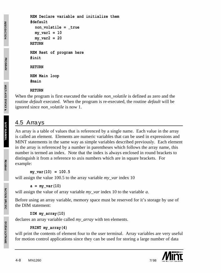
When the program is first executed the variable non_volatile is defined as zero and theroutine default executed. When the program is re-executed, the routine default will beignored since non_volatile is now 1.
4.5 ArraysAn array is a table of values that is referenced by a single name. Each value in the arrayis called an element. Elements are numeric variables that can be used in expressions andMINT statements in the same way as simple variables described previously. Each elementin the array is referenced by a number in parentheses which follows the array name, thisnumber is termed an index. Note that the index is always enclosed in round brackets todistinguish it from a reference to axis numbers which are in square brackets. Forexample:
my_var(10) = 100.5
will assign the value 100.5 to the array variable my_var index 10
a = my_var(10)
will assign the value of array variable my_var index 10 to the variable a.
Before using an array variable, memory space must be reserved for it’s storage by use ofthe DIM statement:
DIM my_array(10)
declares an array variable called my_array with ten elements.
PRINT my_array(4)
will print the contents of element four to the user terminal. Array variables are very usefulfor motion control applications since they can be used for storing a large number of data
MN1260 4-97/98
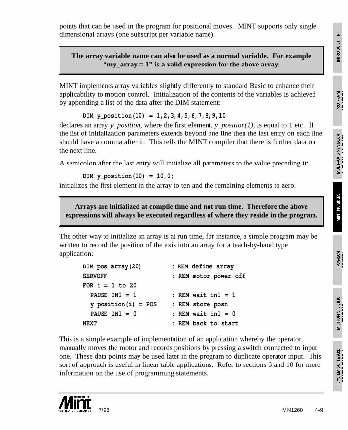
points that can be used in the program for positional moves. MINT supports only singledimensional arrays (one subscript per variable name).
The array variable name can also be used as a normal variable. For example“my_array = 1” is a valid expression for the above array.
MINT implements array variables slightly differently to standard Basic to enhance theirapplicability to motion control. Initialization of the contents of the variables is achievedby appending a list of the data after the DIM statement:
DIM y_position(10) = 1,2,3,4,5,6,7,8,9,10
declares an array y_position, where the first element, y_position(1), is equal to 1 etc. Ifthe list of initialization parameters extends beyond one line then the last entry on each lineshould have a comma after it. This tells the MINT compiler that there is further data onthe next line.
A semicolon after the last entry will initialize all parameters to the value preceding it:
DIM y_position(10) = 10,0;
initializes the first element in the array to ten and the remaining elements to zero.
Arrays are initialized at compile time and not run time. Therefore the aboveexpressions will always be executed regardless of where they reside in the program.
The other way to initialize an array is at run time, for instance, a simple program may bewritten to record the position of the axis into an array for a teach-by-hand typeapplication:
DIM pos_array(20) : REM define array
SERVOFF : REM motor power offFOR i = 1 to 20
PAUSE IN1 = 1 : REM wait in1 = 1
y_position(i) = POS : REM store posn
PAUSE IN1 = 0 : REM wait in1 = 0NEXT : REM back to start
This is a simple example of implementation of an application whereby the operatormanually moves the motor and records positions by pressing a switch connected to inputone. These data points may be used later in the program to duplicate operator input. Thissort of approach is useful in linear table applications. Refer to sections 5 and 10 for moreinformation on the use of programming statements.
4-10 7/98MN1260
One important difference between MINT and standard Basic is that array variables are notinitialized to zero at run time. This means that data stored in previous executions of theprogram is not lost when the system is turned off.
You have seen how a series of points can be stored in an array in a teach-by-handapplication. Entering this data may be a long process, so it is recommended that you savea back-up copy to disk. Array data may be uploaded and stored on a disk by using astandard terminal emulation program such as the one supplied on disk with this manual(cTERM).
Upload and Download facilities allow you to teach a machine a series of points which arestored as array data, upload the data into your computer using the SAVE command, storeas it a file and then download it, using the LOAD command, to any number of identicalcontrollers. Alternatively, with a memory card attached, array data can be saved andrestored to a memory card, again using the LOAD and SAVE keywords. More detailsabout saving and restoring array data is contained in the following sections.
4.5.1 Off-line Array Storage
A memory card interface is available which supports a 64K or 128K RAM (SmartMoveonly) for memory expansion. The memory card interface is either built into the controller(as with SmartMove), or is supplied as an expansion card. Section 9.1 containsinformation on using the memory card for memory expansion. This sections deals withusing the memory card for expansion of array data.
Consider the following example:
DIM OFFLINE xpos(1000)DIM OFFLINE ypos(1000)
DIM zpos(50)
SERVOFFFOR a = 1 TO 1000
PAUSE IN1 : REM Wait for input 1
xpos(a) = POS.0
ypos(a) = POS.1NEXT
The array data xpos and ypos have both been defined as residing off-line on the memorycard by use of the OFFLINE keyword within the DIM statement. No internal memory isused by the array data. zpos on the other hand resides within the controller memoryspace. Offline array data can then be used throughout the program as though the dataresides within the controller address space.
MN1260 4-117/98
With a 64K RAM card, some 64,256 bytes of memory are free or up to 16,064 arrayelements. A 128K RAM card, as supported by SmartMove, will double this amount of data.
Memory cards can be swapped at any time during program execution, therefore makingthe number of array elements for any program limitless. A memory card must be in placeduring program compilation otherwise an “Out of Memory” error will result. It will thenbe necessary to replace the memory card and reset the controller.
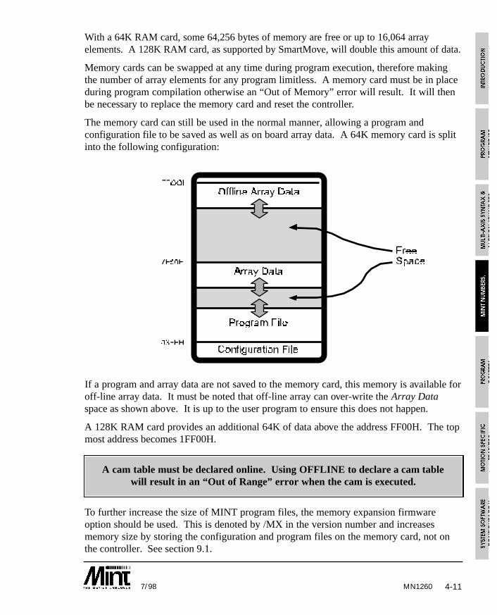
The memory card can still be used in the normal manner, allowing a program andconfiguration file to be saved as well as on board array data. A 64K memory card is splitinto the following configuration:
If a program and array data are not saved to the memory card, this memory is available foroff-line array data. It must be noted that off-line array can over-write the Array Dataspace as shown above. It is up to the user program to ensure this does not happen.
A 128K RAM card provides an additional 64K of data above the address FF00H. The topmost address becomes 1FF00H.
A cam table must be declared online. Using OFFLINE to declare a cam tablewill result in an “Out of Range” error when the cam is executed.
To further increase the size of MINT program files, the memory expansion firmwareoption should be used. This is denoted by /MX in the version number and increasesmemory size by storing the configuration and program files on the memory card, not onthe controller. See section 9.1.
4-12 7/98MN1260
4.5.2 Advanced use of Arrays
Consider an insertion application, whereby the machine must repeatedly move through aseries of points and perform an insertion operation, but different work-pieces require adifferent series of positions. This is an ideal application for array data.
The following code fragment defines two arrays, X and Y, that store fifty data points eachfor an X-Y insertion application:
DIM X(50)
DIM Y(50)
A program to read the data in the arrays and perform the insertion might look somethinglike this (the exact syntax of the move instructions is covered in later sections of thismanual, consider for now only the way that we use the data):
FOR I = 1 TO 50MOVEA = X(I),Y(I) : REM read Ith elements
GO
PAUSE IDLE[0,1] : REM wait for move to finish
OUT1 = 1 : REM output one is connected to..
WAIT = 50 : REM .. the insertion machineOUT1 = 0
NEXT
The statement MOVEA = X(I),Y(I) selects the Ith element of the arrays as the positionsfor the Ith iteration of the FOR loop. If different jobs require different numbers ofinsertion operations, we would probably store the maximum value of the loop as avariable as well.
Array data is stored in the controller memory as a table of four byte variables. Data spaceis limited by memory on board the controller to approximately 4000 elements, dependingon the size of the application program (this can be increased using a memory card and theOFFLINE keyword). Each element is a scaled integer like normal MINT variables, wherethe top three bytes represent an integer value in the range ±8,388,607 and the lower byte isa fractional part with a resolution of 1/256.
The statements:
DIM X(50)
DIM Y(50)
reserve a one hundred element (400 byte) long table of data in the controller’s memory.
For advanced users, it is possible to externally generate the array data for X and Y in theexample program above and download this is to the host without loading a new program.This data might be generated by any application that can produce a series of numbers in
4-137/98 MN1260
ASCII format. For instance, if you wished to interface a CAD (Computer Aided Design)system with your insertion machine, you could write a program that generated the dataformatted as specified in the next section.
Example Program: Teach and Replay
This simple example uses arrays to record 10 XY positions. The operator uses a joystickto move the table around; 3 operator panel keys are labeled ‘teach’ ‘replay’ and ‘record’,which return ‘A’ ‘B’ & ‘C’ up the RS232 port.
Using array data files, it is possible to learn a series of points and to save the array datausing the SAVE command. Likewise, the data can be edited using any standard texteditor, and the new data loaded using the LOAD command.
< MANUAL\TEACH.MNT
REM XY Table Example: teach and replayREM for an insertion application
DIM x_position(10) : REM 10 points of data
DIM y_position(10)GOSUB main
END
#mainLOOP
PRINT “Press Teach or Replay”
key = 0
REM Wait for a key to be pressedWHILE key = 0
key = INKEY : REM Read keyboard
IF key = ‘A’ THEN GOSUB teach
IF key = ‘B’ THEN GOSUB replay
ENDWENDL
RETURN
REM Subroutine to teach points and record in arrays#teach
PRINT “Teach mode” BEEP
WAIT = 1000 : REM Wait one second
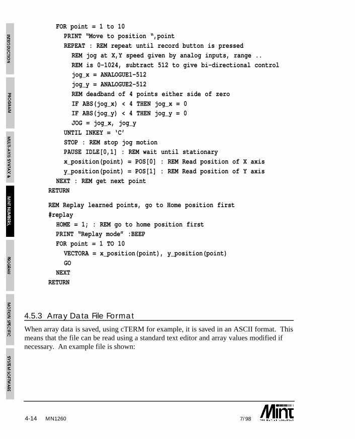
MN12604-14 7/98
FOR point = 1 to 10PRINT “Move to position “,point
REPEAT : REM repeat until record button is pressed
REM jog at X,Y speed given by analog inputs, range ..
REM is 0-1024, subtract 512 to give bi-directional controljog_x = ANALOGUE1-512
jog_y = ANALOGUE2-512
REM deadband of 4 points either side of zero
IF ABS(jog_x) < 4 THEN jog_x = 0IF ABS(jog_y) < 4 THEN jog_y = 0
JOG = jog_x, jog_y
UNTIL INKEY = ‘C’
STOP : REM stop jog motionPAUSE IDLE[0,1] : REM wait until stationary
x_position(point) = POS[0] : REM Read position of X axis
y_position(point) = POS[1] : REM Read position of Y axis
NEXT : REM get next pointRETURN
REM Replay learned points, go to Home position first
#replay
HOME = 1; : REM go to home position firstPRINT “Replay mode” :BEEP
FOR point = 1 TO 10
VECTORA = x_position(point), y_position(point)
GONEXT
RETURN
4.5.3 Array Data File Format
When array data is saved, using cTERM for example, it is saved in an ASCII format. Thismeans that the file can be read using a standard text editor and array values modified ifnecessary. An example file is shown:
MN1260 4-157/98
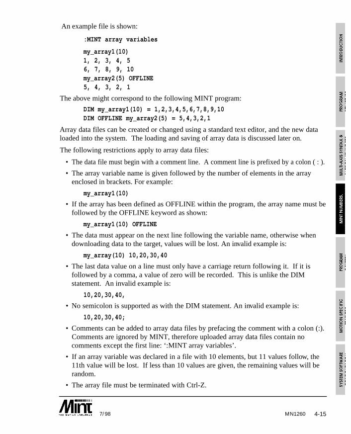
An example file is shown:
:MINT array variables
my_array1(10)1, 2, 3, 4, 56, 7, 8, 9, 10my_array2(5) OFFLINE5, 4, 3, 2, 1
The above might correspond to the following MINT program:
DIM my_array1(10) = 1,2,3,4,5,6,7,8,9,10DIM OFFLINE my_array2(5) = 5,4,3,2,1
Array data files can be created or changed using a standard text editor, and the new dataloaded into the system. The loading and saving of array data is discussed later on.
The following restrictions apply to array data files:
• The data file must begin with a comment line. A comment line is prefixed by a colon ( : ).
• The array variable name is given followed by the number of elements in the arrayenclosed in brackets. For example:
my_array1(10)
• If the array has been defined as OFFLINE within the program, the array name must befollowed by the OFFLINE keyword as shown:
my_array1(10) OFFLINE
• The data must appear on the next line following the variable name, otherwise whendownloading data to the target, values will be lost. An invalid example is:
my_array(10) 10,20,30,40
• The last data value on a line must only have a carriage return following it. If it isfollowed by a comma, a value of zero will be recorded. This is unlike the DIMstatement. An invalid example is:
10,20,30,40,
• No semicolon is supported as with the DIM statement. An invalid example is:
10,20,30,40;
• Comments can be added to array data files by prefacing the comment with a colon (:).Comments are ignored by MINT, therefore uploaded array data files contain nocomments except the first line: ‘:MINT array variables’.
• If an array variable was declared in a file with 10 elements, but 11 values follow, the11th value will be lost. If less than 10 values are given, the remaining values will berandom.
• The array file must be terminated with Ctrl-Z.
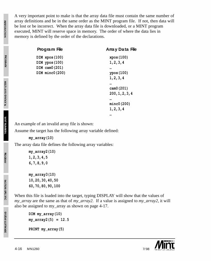
MN12604-16 7/98
A very important point to make is that the array data file must contain the same number ofarray definitions and be in the same order as the MINT program file. If not, then data willbe lost or be incorrect. When the array data file is downloaded, or a MINT programexecuted, MINT will reserve space in memory. The order of where the data lies inmemory is defined by the order of the declarations.
Program File Array Data File
DIM xpos(100) xpos(100)DIM ypos(100) 1,2,3,4DIM cam0(201) …DIM minc0(200) ypos(100)
1,2,3,4…cam0(201)200,1,2,3,4…minc0(200)1,2,3,4…
An example of an invalid array file is shown:
Assume the target has the following array variable defined:
my_array(10)
The array data file defines the following array variables:
my_array2(10)
1,2,3,4,5
6,7,8,9,0
my_array3(10)
10,20,30,40,50
60,70,80,90,100
When this file is loaded into the target, typing DISPLAY will show that the values ofmy_array are the same as that of my_array2. If a value is assigned to my_array2, it willalso be assigned to my_array as shown on page 4-17.
DIM my_array(10)
my_array2(5) = 12.5
PRINT my_array(5)
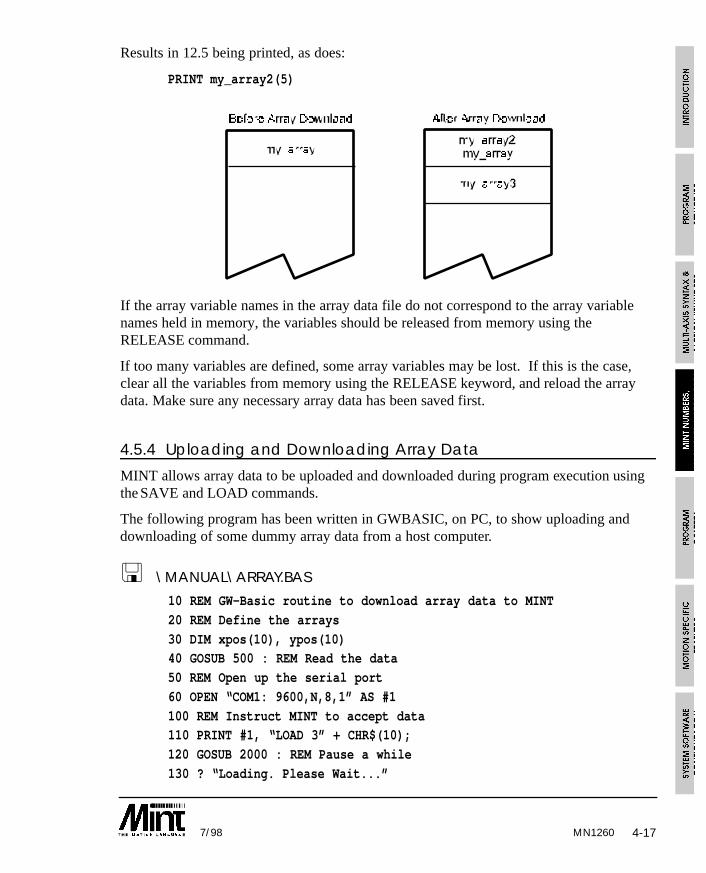
MN1260 4-177/98
Results in 12.5 being printed, as does:
PRINT my_array2(5)
If the array variable names in the array data file do not correspond to the array variablenames held in memory, the variables should be released from memory using theRELEASE command.
If too many variables are defined, some array variables may be lost. If this is the case,clear all the variables from memory using the RELEASE keyword, and reload the arraydata. Make sure any necessary array data has been saved first.
4.5.4 Uploading and Downloading Array Data
MINT allows array data to be uploaded and downloaded during program execution usingthe SAVE and LOAD commands.
The following program has been written in GWBASIC, on PC, to show uploading anddownloading of some dummy array data from a host computer.
< \MANUAL\ARRAY.BAS
10 REM GW-Basic routine to download array data to MINT
20 REM Define the arrays
30 DIM xpos(10), ypos(10)40 GOSUB 500 : REM Read the data
50 REM Open up the serial port
60 OPEN “COM1: 9600,N,8,1” AS #1
100 REM Instruct MINT to accept data110 PRINT #1, “LOAD 3” + CHR$(10);
120 GOSUB 2000 : REM Pause a while
130 ? “Loading. Please Wait...”
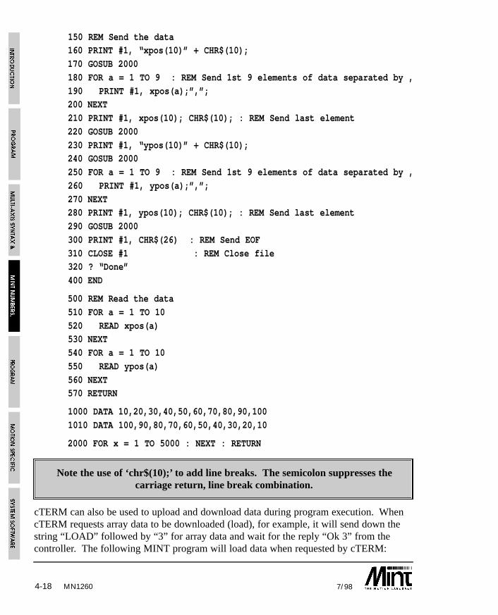
MN12604-18 7/98
150 REM Send the data160 PRINT #1, “xpos(10)” + CHR$(10);
170 GOSUB 2000
180 FOR a = 1 TO 9 : REM Send 1st 9 elements of data separated by ,
190 PRINT #1, xpos(a);”,”;200 NEXT
210 PRINT #1, xpos(10); CHR$(10); : REM Send last element
220 GOSUB 2000
230 PRINT #1, “ypos(10)” + CHR$(10);240 GOSUB 2000
250 FOR a = 1 TO 9 : REM Send 1st 9 elements of data separated by ,
260 PRINT #1, ypos(a);”,”;
270 NEXT280 PRINT #1, ypos(10); CHR$(10); : REM Send last element
290 GOSUB 2000
300 PRINT #1, CHR$(26) : REM Send EOF
310 CLOSE #1 : REM Close file320 ? “Done”
400 END
500 REM Read the data
510 FOR a = 1 TO 10
520 READ xpos(a)530 NEXT
540 FOR a = 1 TO 10
550 READ ypos(a)
560 NEXT570 RETURN
1000 DATA 10,20,30,40,50,60,70,80,90,100
1010 DATA 100,90,80,70,60,50,40,30,20,10
2000 FOR x = 1 TO 5000 : NEXT : RETURN
Note the use of ‘chr$(10);’ to add line breaks. The semicolon suppresses thecarriage return, line break combination.
cTERM can also be used to upload and download data during program execution. WhencTERM requests array data to be downloaded (load), for example, it will send down thestring “LOAD” followed by “3” for array data and wait for the reply “Ok 3” from thecontroller. The following MINT program will load data when requested by cTERM:
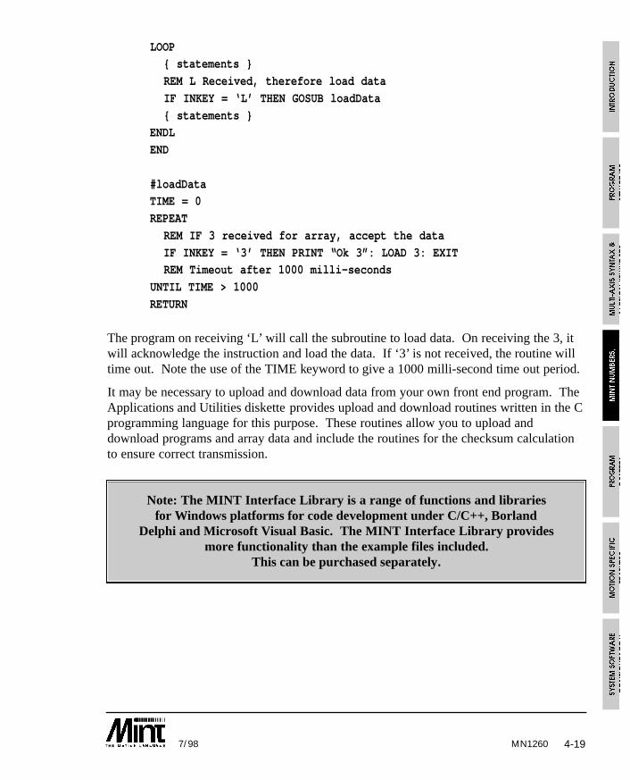
MN1260 4-197/98
LOOP{ statements }
REM L Received, therefore load data
IF INKEY = ‘L’ THEN GOSUB loadData
{ statements }ENDL
END
#loadDataTIME = 0
REPEAT
REM IF 3 received for array, accept the data
IF INKEY = ‘3’ THEN PRINT “Ok 3”: LOAD 3: EXITREM Timeout after 1000 milli-seconds
UNTIL TIME > 1000
RETURN
The program on receiving ‘L’ will call the subroutine to load data. On receiving the 3, itwill acknowledge the instruction and load the data. If ‘3’ is not received, the routine willtime out. Note the use of the TIME keyword to give a 1000 milli-second time out period.
It may be necessary to upload and download data from your own front end program. TheApplications and Utilities diskette provides upload and download routines written in the Cprogramming language for this purpose. These routines allow you to upload anddownload programs and array data and include the routines for the checksum calculationto ensure correct transmission.
Note: The MINT Interface Library is a range of functions and librariesfor Windows platforms for code development under C/C++, Borland
Delphi and Microsoft Visual Basic. The MINT Interface Library providesmore functionality than the example files included.
This can be purchased separately.
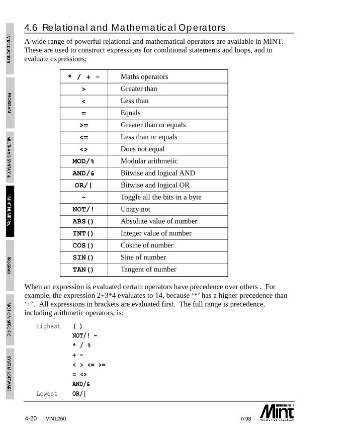
MN12604-20 7/98
4.6 Relational and Mathematical OperatorsA wide range of powerful relational and mathematical operators are available in MINT.These are used to construct expressions for conditional statements and loops, and toevaluate expressions:
* / + - Maths operators
> Greater than
< Less than
= Equals
>= Greater than or equals
<= Less than or equals
<> Does not equal
MOD/% Modular arithmetic
AND/& Bitwise and logical AND
OR/| Bitwise and logical OR
~ Toggle all the bits in a byte
NOT/! Unary not
ABS() Absolute value of number
INT() Integer value of number
COS() Cosine of number
SIN() Sine of number
TAN() Tangent of number
When an expression is evaluated certain operators have precedence over others . Forexample, the expression 2+3*4 evaluates to 14, because ‘*’ has a higher precedence than‘+’. All expressions in brackets are evaluated first. The full range is precedence,including arithmetic operators, is:
Highest ( )NOT/! ~
* / %
+ -
< > <= >== <>
AND/&
Lowest OR/|
4-217/98 MN1260
All relational and logical operators are supported within expressions. These can be usedto construct very powerful conditional statements with ease:
IF IN1 AND (IN2 OR POS > 100) THEN {statement}
Motion variables that can be read are valid within conditional statements, for instance:
PAUSE POS > 50 OR IN1 = 1
will suspend program execution until the position is greater than 50 or input one is high.Any expression or constant that is non zero is defined as true and any that is zero isdefined as false. This gives the user a lot of flexibility in the termination of loops.
count = 1
WHILE IN1 AND count < 100
count = count + 1...
ENDW
will terminate when digital input 1 goes low or count reaches 100.
4.6.1 Performing Bitwise Operations
Logical operators AND/& and OR/| can be used for more than simple comparisons, sincethey actually perform bitwise operations on the variables. For instance, consider theexpression:
5 & 6
is evaluated to 4 i.e. in its binary representation:
0101 & 0100 = 0100
The AND/& operator can therefore be used to mask inputs in conditional expressions:
PAUSE IN AND 12
PAUSE IN2 = 1 OR IN3 = 1
are equivalent since 12 (1100 binary) masks off the lower bits of the inputs (IN is a fourbit binary representation of digital inputs one to four). The advantage of the first option isthat it will execute faster. A binary constant could be used to make the expression morereadable:
PAUSE IN AND 01100PAUSE IN AND 12
are equivalent.
MN12604-22 7/98
OUT = OUT & 15will clear the digital output bits 4 to 7 leaving bit 0 to 3 intact.
OUT = OUT | 15
will set output bits 0 to 3, leaving bits 4 to 7 intact where OUT is used to set the eightdigital output bits. Reading OUT will return the last value written to the outputs.
4.6.2 Trigonometric Functions
The trigonometric functions SIN, COS and TAN are available using the keywords SIN,COS and TAN. There are no inverse functions.
Due to the inaccuracy of floating point numbers in MINT, the values returned from thetrigonometric functions are scaled by a factor a 1000. For example:
SIN 30will return 500.
All the functions will accept an angle in the range of 0 to 360 degrees. Lookup isperformed on a 90 degree table with 1000 elements. This will give an accuracy of approx.1/10th of a degree.
The angle can be expressed as any valid MINT expression but brackets must be used asfollows:
SIN 90 + a
is not the same as:
SIN(90 + a)
The first expression is equivalent to:
(SIN(90)) + a
MN1260 5-17/98
5. Program Control
5.1 Conditional StatementsThree conditional statements are supported in MINT.
• IF .. THEN• IF block structure.
• PAUSE
5.1.1 IF ..THEN statement
Format:
IF <condition> THEN <statements>
The simple IF .. THEN statement is the same as standard versions in Basic. If thecondition is true the statements following THEN and up to the end of the line areexecuted. The condition can be any valid expression, full details of the alternatives aregiven in the section on relational operators.
Examples:
IF POS[1] > 100 THEN SP = 20
IF (a > 12) AND (in1 OR (b > 20)) THEN GOSUB label1Multiple statements are separated by colons if they are to be executed in the same ifstatement.
Example:
IF IN3 THEN STOP : PAUSE IDLE : OUT0 = _off
Note that there is no ELSE statement with the simple IF statement, the IF block structuremust be used if an ELSE is required.
5.1.2 IF block structure
Whereas the IF THEN statement can only be used to conditionally execute a single line ofcommands, the IF block structure can execute a series of commands. It has the followingstructure.
Format:
IF condition DO
{statements} : REM Execute if condition is true
{ELSE
statements} : REM Execute if condition is falseENDIF
MN12605-2 7/98
If the condition is true, the statements up to the ELSE or ENDIF will be executed. If thecondition is false, the statements after the ELSE or ENDIF statement will be executed.The ELSE is optional, statements following the ELSE will be executed only if thecondition is false.
Example 1:
IF INKEY = ‘A’ DO
OUT1 = _onFOR a = 1 to 10
VR = pos_x(a), pos_y(a) : GO
NEXT
OUT1 = _offELSE
JOG = 40, 50
ENDIF
Example 2:IF IN2 OR !IN4 DO
STOP
PAUSE IDLE[0,1]
OUT1 = _on
ENDIF
IF THEN should be used for execution speed if no ELSE is required andall the statements can fit onto one line.
IF .. ENDIF constructs can be nested (IF within an IF) up to 30 levels. An example of twolevels of nesting is:
IF a = 5 DO
{statements}IF b = 2 DO
c = 3
{statements}
ENDIF{statements}
ELSE
d = 1
ENDIF
MN1260 5-37/98
5.1.3 PAUSE statement
Format:
PAUSE <expression>
The PAUSE keyword stops program execution until condition a is true. This has manyuses in synchronizing motion and waiting for inputs.
For example:
PAUSE IN1 = 1
will halt program execution until input bit 1 reads 1. Alternatively:
PAUSE IN1is the same as the previous example but is quicker to evaluate and saves code space.
PAUSE !IN1
PAUSE IN1
pause until a rising edge is seen on input bit 1.
PAUSE POS > 300
pauses until POS (axis position) is greater than 300. Due to the finite time that this looptakes to operate, the axis position upon executing the next line of code may be slightlygreater than 300, especially at high motor speeds.
Example 2:
PAUSE IDLE[0,1]
will pause until both axis 0 and axis 1 are idle. i.e. the mode is zero.
PAUSE with no parameters will stop program execution until a key is pressed at the user’sterminal. This is useful for operator interaction. Using INKEY to read the keyboard, thestatement:
PAUSE INKEY = ‘y’
will suspend program execution until key ‘y’ is pressed.
PAUSE INKEYwill wait for any key press.
PAUSE INKEY = 0
will clear the serial port buffer.
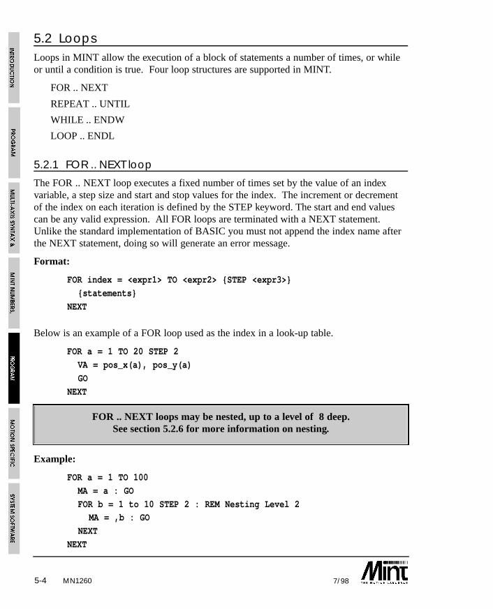
MN12605-4 7/98
5.2 LoopsLoops in MINT allow the execution of a block of statements a number of times, or whileor until a condition is true. Four loop structures are supported in MINT.
FOR .. NEXT
REPEAT .. UNTIL
WHILE .. ENDW
LOOP .. ENDL
5.2.1 FOR .. NEXT loop
The FOR .. NEXT loop executes a fixed number of times set by the value of an indexvariable, a step size and start and stop values for the index. The increment or decrementof the index on each iteration is defined by the STEP keyword. The start and end valuescan be any valid expression. All FOR loops are terminated with a NEXT statement.Unlike the standard implementation of BASIC you must not append the index name afterthe NEXT statement, doing so will generate an error message.
Format:
FOR index = <expr1> TO <expr2> {STEP <expr3>}
{statements}
NEXT
Below is an example of a FOR loop used as the index in a look-up table.
FOR a = 1 TO 20 STEP 2
VA = pos_x(a), pos_y(a)
GO
NEXT
FOR .. NEXT loops may be nested, up to a level of 8 deep.See section 5.2.6 for more information on nesting.
Example:
FOR a = 1 TO 100
MA = a : GO
FOR b = 1 to 10 STEP 2 : REM Nesting Level 2MA = ,b : GO
NEXT
NEXT
MN1260 5-57/98
5.2.2 REPEAT .. UNTIL loop
REPEAT .. UNTIL executes the statements within the loop until the condition after theUNTIL is true.
Format:
REPEAT
{statements}UNTIL <condition>
Example:
a = 0
REPEAT
MOVER = 1 : GOPRINT “Position is: “,POS; : BOL
UNTIL POS > 100
When the UNTIL statement is true, the loop will terminate. A repeat loop will alwaysexecute at least once. The EXIT statement can be used to prematurely terminate aREPEAT loop.
REPEAT .. UNTIL loops can be nested up to 10 levels.See section 5.2.6 for more information on nesting.
Example 2:
REPEAT : UNTIL INKEY = 0
this example will clear the serial port buffer. INKEY returns the value 0 when the serialbuffer contents are empty. This can be replaced by:
PAUSE INKEY = 0
5.2.3 WHILE .. ENDW loop
WHILE .. ENDW will execute until the condition after the WHILE becomes false. Unlikea REPEAT loop which will always execute at least once, a WHILE loop will only executeif the condition is true.
Example:
WHILE IN1
JOG = A1 - 127
ENDWSTOP
MN12605-6 7/98
jogs the motor at a value set by analog port 1. When input 1 goes low the loop terminatesand the motor will stop.
The EXIT statement can be used to prematurely terminate a WHILE loop.
WHILE .. ENDW loops can be nested up to 10 levels.See section 5.2.6 for more information on nesting.
5.2.4 LOOP .. ENDL loop
LOOP .. ENDL simply loops round indefinitely, for instance:
LOOPJOG = IN : REM speed set by IN0..6
IF IN7 = 1 THEN EXIT
ENDL
loops round forever reading the digital inputs and jogging the motor at a speed set by thebinary value of user inputs zero to six.
Example 2:
GOSUB start
LOOP
key = INKEY
IF key = ‘A’ THEN GOSUB teachIF key = ‘B’ THEN GOSUB replay
IF key = ‘C’ THEN GOSUB saveData
ENDL
provides a simple menu interface. Loops round forever checking the keyboard and actsaccordingly on certain key presses.
The LOOP structure can be terminated with the EXIT keyword.
LOOP .. ENDL loops can be nested up to 10 levels.See section 5.2.6 for more information on nesting.
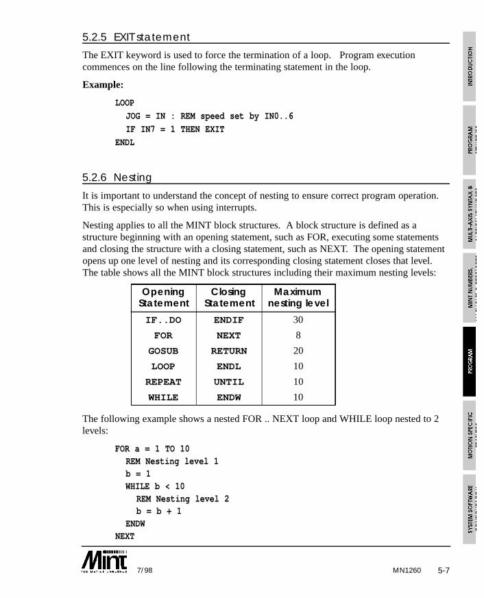
MN1260 5-77/98
5.2.5 EXIT statement
The EXIT keyword is used to force the termination of a loop. Program executioncommences on the line following the terminating statement in the loop.
Example:
LOOP
JOG = IN : REM speed set by IN0..6
IF IN7 = 1 THEN EXIT
ENDL
5.2.6 Nesting
It is important to understand the concept of nesting to ensure correct program operation.This is especially so when using interrupts.
Nesting applies to all the MINT block structures. A block structure is defined as astructure beginning with an opening statement, such as FOR, executing some statementsand closing the structure with a closing statement, such as NEXT. The opening statementopens up one level of nesting and its corresponding closing statement closes that level.The table shows all the MINT block structures including their maximum nesting levels:
Opening Closing MaximumStatement Statement nesting level
IF..DO ENDIF 30
FOR NEXT 8
GOSUB RETURN 20
LOOP ENDL 10
REPEAT UNTIL 10
WHILE ENDW 10
The following example shows a nested FOR .. NEXT loop and WHILE loop nested to 2levels:
FOR a = 1 TO 10REM Nesting level 1b = 1WHILE b < 10
REM Nesting level 2b = b + 1
ENDWNEXT

MN12605-8 7/98
In the example above, the WHILE statement gives a nesting level of 2, and if the WHILEexpression evaluates to false, i.e. b >= 10, the ENDW statement closes that level.
It is important to realize that MINT restricts the level of nesting for each block structure asshown in the table above, but there is no restriction to the number of block structures thatcan be implemented in a program. As can be seen from the table, most of the blockstructures have a maximum nesting of 10. MINT will however allow you to mix thesestructures up to a maximum of 30 levels. It is therefore possible to nest 8 FOR loops, 10REPEAT loops and 10 WHILE loops for example. Subroutines can however be nested upto 20 deep, i.e. a subroutine can call another subroutine which in turn can call another, upto the maximum allowed.
Interrupt routines are treated as subroutines and when called will result in an extra level ofnesting, as with GOSUB, until it is terminated with RETURN. Since interrupts can occurat any time during program execution, it is very important that the maximum possiblelevel of nesting in the program should conform to the following: Assuming that nointerrupt routine uses block constructs, the maximum number of nesting allowed is:
30 - (number of interrupt routines defined)
The maximum nesting of subroutines is:
20 - (number of interrupt routines defined)
If the level of nesting is at its maximum value when the interrupt routine is called, MINTwill ignore the interrupt request until the nesting level reduces by 1. See section 5.3.2 formore details on interrupts.
The subroutines #STOP and #ONERROR are considered to be interrupt routinesSee section 5.3.
5.3 SubroutinesSubroutines in MINT are called using the GOSUB command. Since MINT does notsupport line numbers, all subroutines are referenced by labels. A label is prefixed with ahash ‘#’ and can be any combination of up to ten alphanumeric characters. If two labelshave the same name, an “Invalid label” error is generated at compile time.
#my_sub
{statements}RETURN
defines a subroutine called my_sub which is called by:
GOSUB my_sub
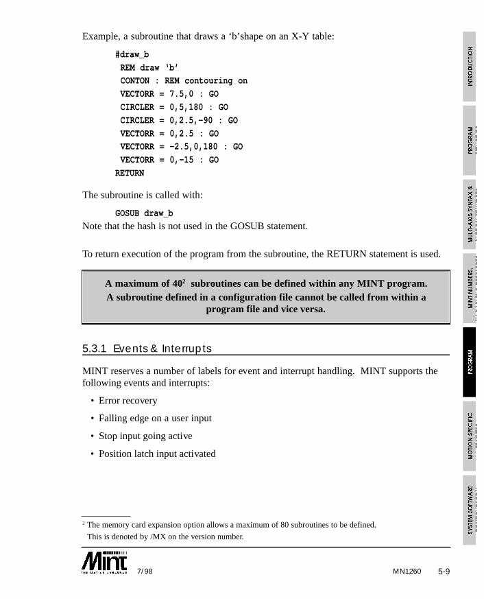
MN1260 5-97/98
Example, a subroutine that draws a ‘b’shape on an X-Y table:
#draw_b
REM draw ‘b’CONTON : REM contouring on
VECTORR = 7.5,0 : GO
CIRCLER = 0,5,180 : GO
CIRCLER = 0,2.5,-90 : GO
VECTORR = 0,2.5 : GOVECTORR = -2.5,0,180 : GO
VECTORR = 0,-15 : GO
RETURN
The subroutine is called with:
GOSUB draw_b
Note that the hash is not used in the GOSUB statement.
To return execution of the program from the subroutine, the RETURN statement is used.
A maximum of 402 subroutines can be defined within any MINT program. A subroutine defined in a configuration file cannot be called from within a
program file and vice versa.
5.3.1 Events & Interrupts
MINT reserves a number of labels for event and interrupt handling. MINT supports thefollowing events and interrupts:
• Error recovery
• Falling edge on a user input
• Stop input going active
• Position latch input activated
2 The memory card expansion option allows a maximum of 80 subroutines to be defined.
This is denoted by /MX on the version number.
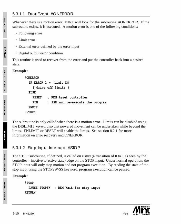
MN12605-10 7/98
5.3.1.1 Error Event: #ONERROR
Whenever there is a motion error, MINT will look for the subroutine, #ONERROR. If thesubroutine exists, it is executed. A motion error is one of the following conditions:
• Following error
• Limit error
• External error defined by the error input
• Digital output error condition
This routine is used to recover from the error and put the controller back into a desiredstate.
Example:
#ONERROR
IF ERROR.1 = _limit DO
{ drive off limits }ELSE
RESET : REM Reset controller
RUN : REM and re-execute the program
ENDIFRETURN
The subroutine is only called when there is a motion error. Limits can be disabled usingthe DISLIMIT keyword so that powered movement can be undertaken while beyond thelimits. ENLIMIT or RESET will enable the limits. See section 8.2.1 for moreinformation on error recovery and ONERROR.
5.3.1.2 Stop Input Interrupt: #STOP
The STOP subroutine, if defined, is called on rising (a transition of 0 to 1 as seen by thecontroller – inactive to active state) edge on the STOP input. Under normal operation, theSTOP input will only stop motion and not program execution. By reading the state of thestop input using the STOPSW/SS keyword, program execution can be paused.
Example:
#STOP
PAUSE STOPSW : REM Wait for stop inputRETURN

MN1260 5-117/98
The #STOP routine will not be called if the #ONERROR routine is called.#STOP will be called when #ONERROR terminates.
5.3.2 Digital Input Interrupt: #IN0 .. #IN7
MINT allows you to define an interrupt routine for each of the 8 digital inputs. Aninterrupt routine is defined by the subroutines #IN0 to #IN7, where #IN0 is the interruptroutine for digital input 0, #IN1 for digital input 1 an so on. If MINT detects any of thesesubroutines, the appropriate routine is called in response to a falling (a transition of 1 to 0as seen by the controller – active to inactive state) edge on the input. The routine is calledonly after the current statement has been completed.
Example of an interrupt routine:
#IN5
REM Interrupt routine for input 5OUT1 = 1 : REM Write to output 1
RETURN
Notes on interrupts and events:
Interrupt routines are executed only after the current statement has been executed withthe exception of GO, PAUSE and WAIT.
IF IN1 AND IN2 THEN SPEED = 100 : MOVEA = 0 : GO^ ^ ^ ^
• The points at which an interrupts can occur are marked with ^. A change of state inthe input is sampled once every 2 milliseconds (or 1 millisecond if LOOPTIME is 1).
• Interrupt routines must not include the INPUT statement.
• Interrupts are detected in the servo loop closure and therefore the input must be heldin a constant state for at least 2 milli-seconds for an interrupt to occur (this willdecrease to 1 ms if a loop closure time of 1ms is used)
• Once in the interrupt routine, it cannot not be interrupted by the same input pin untilthe routine has issued a RETURN statement. They can however be interrupted byanother input. In an input occurs while being serviced by the interrupt routine, it willbe buffered. Reading IPEND will return the status of all buffered input interrupts.
• If a simultaneous interrupt occurs, MINT uses a priority scheme to determine whichinterrupt is serviced first. #IN7 has a higher priority than #IN6 which in turn has ahigher priority than #IN5 and so on. If for example, an interrupt occurs on input 6and input 3, the interrupt routine for input 6, #IN6, will be serviced before that ofinput 3, #IN3. If the interrupts are not simultaneous then an interrupt subroutine canbe interrupted by any other interrupt routine.
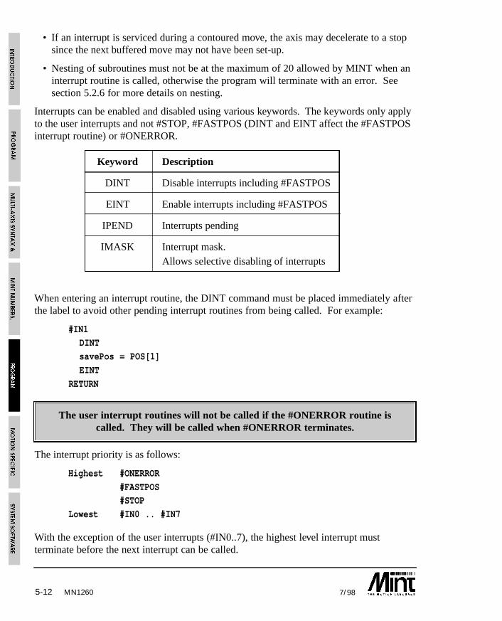
5-12 7/98MN1260
• If an interrupt is serviced during a contoured move, the axis may decelerate to a stopsince the next buffered move may not have been set-up.
• Nesting of subroutines must not be at the maximum of 20 allowed by MINT when aninterrupt routine is called, otherwise the program will terminate with an error. Seesection 5.2.6 for more details on nesting.
Interrupts can be enabled and disabled using various keywords. The keywords only applyto the user interrupts and not #STOP, #FASTPOS (DINT and EINT affect the #FASTPOSinterrupt routine) or #ONERROR.
Keyword Description
DINT Disable interrupts including #FASTPOS
EINT Enable interrupts including #FASTPOS
IPEND Interrupts pending
IMASK Interrupt mask. Allows selective disabling of interrupts
When entering an interrupt routine, the DINT command must be placed immediately afterthe label to avoid other pending interrupt routines from being called. For example:
#IN1DINT
savePos = POS[1]
EINT
RETURN
The user interrupt routines will not be called if the #ONERROR routine iscalled. They will be called when #ONERROR terminates.
The interrupt priority is as follows:
Highest #ONERROR
#FASTPOS#STOP
Lowest #IN0 .. #IN7
With the exception of the user interrupts (#IN0..7), the highest level interrupt mustterminate before the next interrupt can be called.
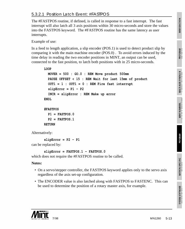
5-137/98
5.3.2.1 Position Latch Event: #FASTPOS
The #FASTPOS routine, if defined, is called in response to a fast interrupt. The fastinterrupt will also latch all 3 axis positions within 30 micro-seconds and store the valuesinto the FASTPOS keyword. The #FASTPOS routine has the same latency as userinterrupts.
Example of use:
In a feed to length application, a slip encoder (POS.1) is used to detect product slip bycomparing it with the main machine encoder (POS.0) . To avoid errors induced by thetime delay in reading the two encoder positions in MINT, an output can be used,connected to the fast position, to latch both positions with in 25 micro-seconds.
LOOP
MOVER = 500 : GO.0 : REM Move product 500mm
PAUSE OFFSET < 15 : REM Wait for last 15mm of productOUT1 = 1 : OUT1 = 0 : REM Fire fast interrupt
slipError = P1 - P2
INCR = slipError : REM Make up error
ENDL
#FASTPOS
P1 = FASTPOS.0
P2 = FASTPOS.1
RETURN
Alternatively:
slipError = P2 - P1
can be replaced by:
slipError = FASTPOS.1 - FASTPOS.0which does not require the #FASTPOS routine to be called.
Notes:
• On a servo/stepper controller, the FASTPOS keyword applies only to the servo axisregardless of the axis set-up configuration.
• The ENCODER value is also latched along with FASTPOS to FASTENC. This canbe used to determine the position of a rotary master axis, for example.
MN1260
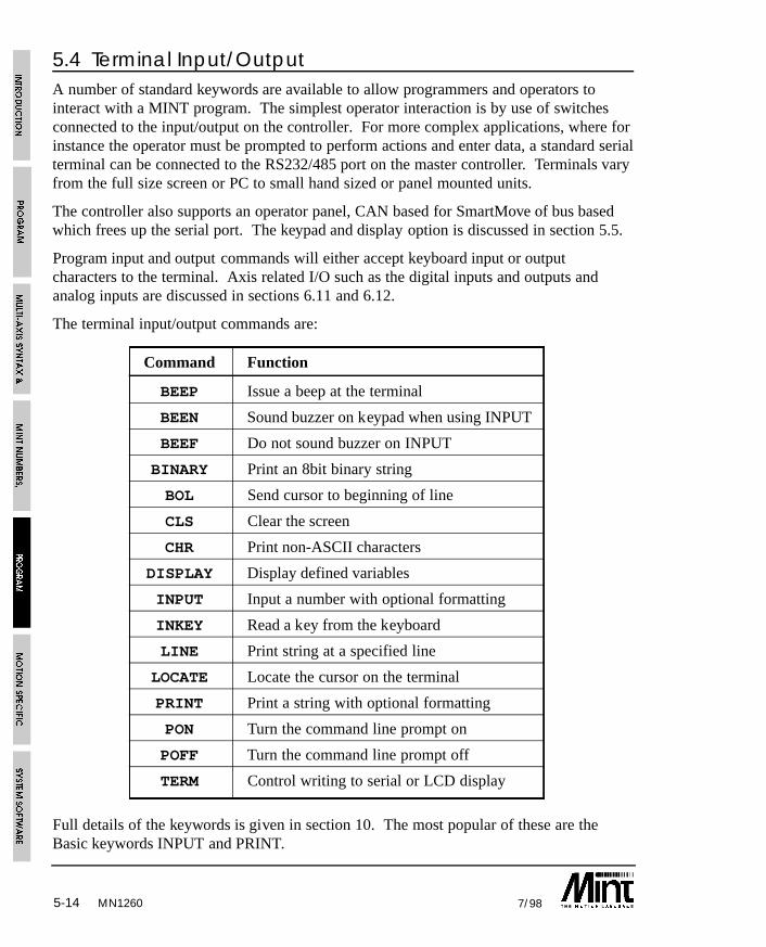
5-14 7/98MN1260
5.4 Terminal Input/OutputA number of standard keywords are available to allow programmers and operators tointeract with a MINT program. The simplest operator interaction is by use of switchesconnected to the input/output on the controller. For more complex applications, where forinstance the operator must be prompted to perform actions and enter data, a standard serialterminal can be connected to the RS232/485 port on the master controller. Terminals varyfrom the full size screen or PC to small hand sized or panel mounted units.
The controller also supports an operator panel, CAN based for SmartMove of bus basedwhich frees up the serial port. The keypad and display option is discussed in section 5.5.
Program input and output commands will either accept keyboard input or outputcharacters to the terminal. Axis related I/O such as the digital inputs and outputs andanalog inputs are discussed in sections 6.11 and 6.12.
The terminal input/output commands are:
Command Function
BEEP Issue a beep at the terminal
BEEN Sound buzzer on keypad when using INPUT
BEEF Do not sound buzzer on INPUT
BINARY Print an 8bit binary string
BOL Send cursor to beginning of line
CLS Clear the screen
CHR Print non-ASCII characters
DISPLAY Display defined variables
INPUT Input a number with optional formatting
INKEY Read a key from the keyboard
LINE Print string at a specified line
LOCATE Locate the cursor on the terminal
PRINT Print a string with optional formatting
PON Turn the command line prompt on
POFF Turn the command line prompt off
TERM Control writing to serial or LCD display
Full details of the keywords is given in section 10. The most popular of these are theBasic keywords INPUT and PRINT.
5-157/98
5.4.1 PRINT Statement
Strings may be printed with the PRINT command, delimited by double quotes.Expressions and strings may be separated by semicolons or commas. A comma will causethe next argument to print directly after the previous one. A semicolon will print the nextargument at the next tab position, where each tab position is at every 8 characters.Another PRINT statement will cause a line feed.
Example:
PRINT “The present x-y position is”
PRINT “x = “,POS[0];”y = “,POS[1]
Typical terminal output:
The present x-y position is:
x = 25 y = 15
PRINT may be abbreviated to ?. For example:
? a
Example 2:
LOOP : ? POS.0; POS.1; : BOL : ENDLthis will continuously print the position of axis 0 and axis 1 on the same line. This can beuseful for checking that an encoder is correctly wired up.
Expressions can be formatted using the USING parameter. For example:
PRINT 1234.5 USING 5,2
will display:
01234.50
where 5 dictates the number of integer places and 2 the number of fractional places. Toprinted a signed number, a negative integer place is given.
Example:
PRINT 1235.5 USING -5,1
will display:
+01234.5
If no fractional part is given, an integer number is printed:
Example:
PRINT 1234.5 USING 4
will display:
1234
MN1260
5-16 7/98
this is the same as:
PRINT INT(1234.5)
The LINE keyword is the same as PRINT but will display a string at the specified line.This is used for the standard keypad and display and will clear all characters to the end ofthe line. For example:
LINE 2, “A = “, A USING 3,2will print the value of A at line 2 using formatted output. The remaining 11 characters onthe display will be cleared.
The keyword BINARY works like PRINT, except an 8 bit number is printed in its binaryrepresentation. Negative numbers are printed in their two’s complement form.
Example:
BINARY “7 in binary is: “, 7
will display:
7 in binary is 00000111
5.4.2 INPUT Statement
INPUT is similar to standard Basic input supporting an optional string, followed by acomma, then a variable name. For example:
INPUT “Enter a number”,a
Terminal output:
Enter a number ?Only numeric input is accepted, any other characters are ignored. If the input string isinvalid the user will be requested to re-enter the number. Pressing return on an empty linewill retain the variable value. Multiple inputs cannot be separated by commas on thesame line as with most Basics.
Input can be formatted using the USING parameter:
INPUT a USING 5,2
will accept input with 5 integer places and 2 fractional places and no sign. Pressingdecimal dot will move the cursor to the number immediately after the decimal place.
Example 2:
INPUT a USING -5,2
will accept input with 5 integer places and 2 fractional places. The input can also besigned. Pressing ‘-’ will toggle the sign of the input value.
MN1260
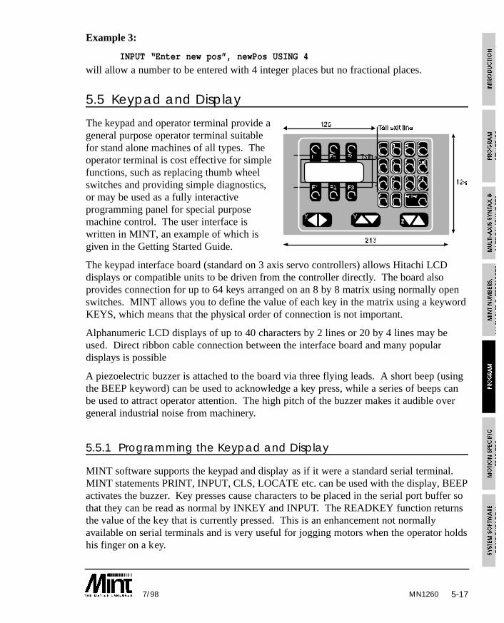
5-177/98
Example 3:
INPUT “Enter new pos”, newPos USING 4
will allow a number to be entered with 4 integer places but no fractional places.
5.5 Keypad and Display
The keypad and operator terminal provide ageneral purpose operator terminal suitablefor stand alone machines of all types. Theoperator terminal is cost effective for simplefunctions, such as replacing thumb wheelswitches and providing simple diagnostics,or may be used as a fully interactiveprogramming panel for special purposemachine control. The user interface iswritten in MINT, an example of which isgiven in the Getting Started Guide.
The keypad interface board (standard on 3 axis servo controllers) allows Hitachi LCDdisplays or compatible units to be driven from the controller directly. The board alsoprovides connection for up to 64 keys arranged on an 8 by 8 matrix using normally openswitches. MINT allows you to define the value of each key in the matrix using a keywordKEYS, which means that the physical order of connection is not important.
Alphanumeric LCD displays of up to 40 characters by 2 lines or 20 by 4 lines may beused. Direct ribbon cable connection between the interface board and many populardisplays is possible
A piezoelectric buzzer is attached to the board via three flying leads. A short beep (usingthe BEEP keyword) can be used to acknowledge a key press, while a series of beeps canbe used to attract operator attention. The high pitch of the buzzer makes it audible overgeneral industrial noise from machinery.
5.5.1 Programming the Keypad and Display
MINT software supports the keypad and display as if it were a standard serial terminal.MINT statements PRINT, INPUT, CLS, LOCATE etc. can be used with the display, BEEPactivates the buzzer. Key presses cause characters to be placed in the serial port buffer sothat they can be read as normal by INKEY and INPUT. The READKEY function returnsthe value of the key that is currently pressed. This is an enhancement not normallyavailable on serial terminals and is very useful for jogging motors when the operator holdshis finger on a key.
MN1260
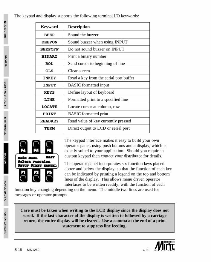
The keypad and display supports the following terminal I/O keywords:
Keyword Description
BEEP Sound the buzzer
BEEPON Sound buzzer when using INPUT
BEEPOFF Do not sound buzzer on INPUT
BINARY Print a binary number
BOL Send cursor to beginning of line
CLS Clear screen
INKEY Read a key from the serial port buffer
INPUT BASIC formatted input
KEYS Define layout of keyboard
LINE Formatted print to a specified line
LOCATE Locate cursor at column, row
PRINT BASIC formatted print
READKEY Read value of key currently pressed
TERM Direct output to LCD or serial port
The keypad interface makes it easy to build your ownoperator panel, using push buttons and a display, which isexactly suited to your application. Should you require acustom keypad then contact your distributor for details.
The operator panel incorporates six function keys placedabove and below the display, so that the function of each keycan be indicated by printing a legend on the top and bottomlines of the display. This allows menu driven operatorinterfaces to be written readily, with the function of each
function key changing depending on the menu. The middle two lines are used formessages or operator prompts.
Care must be taken when writing to the LCD display since the display does notscroll. If the last character of the display is written to followed by a carriagereturn, the entire display will be cleared. Use a comma at the end of a print
statement to suppress line feeding.
5-18 7/98MN1260

5-197/98
Example:
KEYS “”
LOOPLINE 1, “ EXIT”
LINE 2, “Sample keypad”
LINE 3, “Program”
LINE 4, “SETUP START MANUAL”,
key = 0REPEAT
key = INKEY
IF key = ‘A’ THEN BEEP: GOSUB setup
IF key = ‘B’ THEN BEEP: GOSUB startIF key = ‘C’ THEN BEEP: GOSUB manual
IF key = ‘F’ THEN BEEP: END
UNTIL key <> 0
ENDL
#start
REM Code here
RETURN
#start
REM Code here
RETURN
#manual
REM Code here
RETURN
Note the use of BEEP to provide audible feedback to the operator. BEEPON can also beused for this purpose. Also note the comma at the end of LINE 4 statement. This is usedto suppress line feeding and clearing the screen.
The KEYS statement at the beginning of the program is used to enable the keypad. If acustom keypad is used, the KEYS keyword is used to define the actual keys on thekeypad. See section 10 for further details.
Using the keypad interface, it is possible to read the currently pressed key usingREADKEY. This is unlike INKEY which returns the next keypress in the serial inputbuffer. READKEY is useful for jogging motors while a key is pressed.
MN1260
5-20 7/98
Example:
LOOP
IF READKEY = ‘X’ THEN JOG[0] = 10IF READKEY = ‘U’ THEN JOG[0] = -10
IF READKEY = 0 THEN JOG[0] = 0
ENDL
using the X left and right keys on the keypad, the motor will be jogged left or right whilethe key is pressed. When either of the keys are released (READKEY = 0) the motor willcome to a stop.
5.6 Sending Data to an Executing Program
MINT provides two methods of accepting data to an executing program:
• INPUT or INKEY can be used to read the serial port buffer or from the keypad.
• A protected protocol that allows the host computer to read and write data from/to apre-defined array variable.
5.6.1 Serial Port/Keypad Buffer
Characters received by the serial port are stored in a 128 character circular buffer untilthey are read by MINT. Use of this buffer is totally transparent to the user during normalprinting and input routines in MINT.
The buffer enables you to send information to a card at any time for use in a MINTprogram running on board.
By default, MINT receives data from both the keypad and the serial port. To switchbetween the 2, use the TERM keyword. For example:
TERM = _lcd
will direct all terminal I/O to the keypad and lcd display only. Note that Ctrl-E can beused to restore the terminal I/O state back to the serial port.
MN1260
5-217/98
5.6.2 Reading Data from the Serial Buffer using INKEY
Data may be extracted from the serial buffer by the use of INKEY or INPUT keywords.
INKEY is used to read a single character from the buffer. IF no character is present it willreturn zero, otherwise it returns the ASCII value of the character. (ASCII is aninternational standard defining binary equivalents to alphanumeric characters).
INKEY always returns the uppercase value of the characters A-Z. Thus:
MY_VAR = INKEY
will return the value 65 (the ASCII value of ‘A’) to the variable MY_VAR if the character‘A’ or ‘a’is present in the buffer.
You can test the value of MY_VAR using a simple IF statement as shown:
IF MY_VAR = 65 THEN PRINT “A received”
an alternative notation, that does not require knowledge of ASCII values is:
IF MY_VAR = ‘A’ THEN PRINT “A received”
Where the character A is enclosed in single quotes to inform MINT that it’s ASCIIrepresentation should be used.
INPUT can be used to read numeric values from the character buffer into MINT variables.A numeric value is sent down the serial link as its ASCII representation, terminated by acarriage return (ASCII 13 decimal). For instance to send the value 123.45 you wouldsend:
123.45
One very important difference between INKEY and INPUT is that INKEY does not stopprogram execution. It simply returns a zero if there is no data in the buffer and istherefore useful for testing if there is data in the buffer. INPUT will wait until it receivesa valid ASCII number terminated by a carriage return.
The following code section shows how INKEY can be used to clear the serial port:
PAUSE INKEY = 0
Example:
The following simple example programs are designed to illustrate the use of INKEY andINPUT using a terminal emulator program such as cTERM which is included with thecontroller.
The program below is a very simple example showing the use of INKEY. It simply loopsaround waiting for a character to be received (i.e. a non zero value) and then prints theASCII value of the received character. Note use of a question mark, the abbreviation forthe keyword PRINT.
MN1260
5-22 7/98
LOOPa = INKEY
IF a <> 0 THEN ? a
ENDL
The second example is more complex, it waits for ‘a’ or ‘r’ to be received and then acceptsdata which is printed back to the user. In a typical application, this data might be used toperform a MOVEA or MOVER depending on the data received.
LOOP : REM infinite loop
REM wait until a key is pressed
REPEAT : key = INKEY : UNTIL key <> 0
REM read dataIF key = ‘a’ THEN INPUT var1 : ? “a selected, value is “,var1
IF key = ‘r’ THEN INPUT var2 : ? “r selected, value is “,var2
ENDL
Note the use of the variable key to store the keypress before it is tested.
The READKEY keyword is in conjunction with the keypad option to return the value ofthe currently pressed key. Unlike INKEY which returns the next character in the serialport buffer, READKEY will return the key value while the key is pressed, and zero whenno key is pressed.
Example:
LOOP
temp = INKEY : REM Clear the serial port bufferIF READKEY = ‘A’ THEN JOG = 1
IF READKEY = ‘B’ THEN JOG = -1
IF READKEY = 0 THEN JOG = 0
ENDL
will jog the motor in a positive direction only while the key ‘A’ is pressed. The motor isjogged in a negative direction only while ‘B’ is pressed.
MN1260
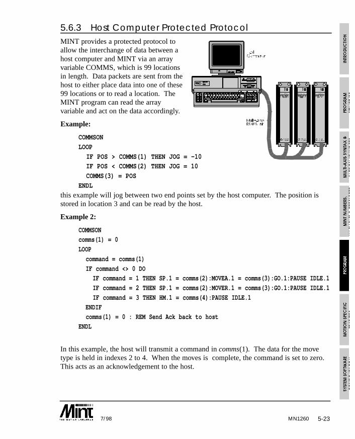
5-237/98
5.6.3 Host Computer Protected ProtocolMINT provides a protected protocol toallow the interchange of data between ahost computer and MINT via an arrayvariable COMMS, which is 99 locationsin length. Data packets are sent from thehost to either place data into one of these99 locations or to read a location. TheMINT program can read the arrayvariable and act on the data accordingly.
Example:
COMMSON
LOOP
IF POS > COMMS(1) THEN JOG = -10IF POS < COMMS(2) THEN JOG = 10
COMMS(3) = POS
ENDL
this example will jog between two end points set by the host computer. The position isstored in location 3 and can be read by the host.
Example 2:
COMMSONcomms(1) = 0
LOOP
command = comms(1)
IF command <> 0 DOIF command = 1 THEN SP.1 = comms(2):MOVEA.1 = comms(3):GO.1:PAUSE IDLE.1
IF command = 2 THEN SP.1 = comms(2):MOVER.1 = comms(3):GO.1:PAUSE IDLE.1
IF command = 3 THEN HM.1 = comms(4):PAUSE IDLE.1
ENDIFcomms(1) = 0 : REM Send Ack back to host
ENDL
In this example, the host will transmit a command in comms(1). The data for the movetype is held in indexes 2 to 4. When the moves is complete, the command is set to zero.This acts as an acknowledgement to the host.
MN1260

5-24 7/98
The COMMSON keyword activates the protected communication and defines the commsarray. Ctrl-E will be disabled and can only be enabled using a special data packet sent bythe host. If cTERM for DOS is used, pressing Shift-F8 will abort protectedcommunications.
The communications protocol is explained in detail in section 12.
MN1260
6-17/98
6. Motion Specific FeaturesThis section deals with the different modes of motion.
6.1 Torque ControlServo Axes Only
Torque control is achieved by controlling the current in the motor armature. For thispurpose the amplifier must be configured as a current amplifier i.e. the analog demandinput to the amplifier relates directly to an output current. Motor torque is directly relatedto current by the expression:
Torque = Armature Current * Kt
where Kt is the motor torque constant. The armature current will depend on the peak andcontinuous rating of the amplifier.
TORQUE will accept any value between -100.0 and +100.0. Where the maximumcorresponds to the peak current from the drive. For example, for a drive with 20A peakcurrent rating:
TORQUE = -50Sets the motor current equal to -10A, i.e. 50% of the peak current. Note that settingtorque to 100% will cause the amplifier to deliver peak current continuously, which maycause it to burn out.
Torque is terminated by the STOP command which puts the controller back into astationary positional control mode. This will cause a moving motor to instantly stop. Toavoid jarring the motor, it is recommended that the motor armature is stationary beforeSTOP is executed. This can be done with a loop:
FOR a = 50 to 1 STEP -1
TQ = a
WAIT = 50NEXT
STOP
where TQ is the abbreviated keyword for TORQUE.
You can freely change between torque, positional and speed control as the applicationdemands however you must make sure an axis is idle first. For example:
TQ = 10
WT = 1000
MOVEA = 100 : GO
MN1260
6-2 7/98
will result in a motion in progress error when the MOVEA command is executed.However, it is possible to enter torque mode from any other mode of motion. Forexample:
MOVEA = 100 : GO
PAUSE DEMAND > = 50TQ = 50
This will move the motor to a desired position until the torque demand to the motorexceeds 50%. Once exceeded, the controller will enter torque mode.
For velocity controlled drives where the motor speed is proportional to theanalog input voltage, TORQUE is useful for setting an open loop speed
demand, especially during commissioning.
6.2 Speed ControlThe JOG keyword provides straightforward speed control, note that this is different to theSPEED keyword which is used to specify the maximum slew speed in a positional move.JOG uses positional feedback from the motor, so that varying load will not affect longterm speed accuracy.
Example:
JOG.1 = 30
If the system has been set up to scale factor in revolutions, this will jog the motor at aspeed of 30 revs/sec.
Note that the GO command is not required. JOG may be changed up and down at anytime, the motor will accelerate to the new speed at the rate specified by ACCEL ordecelerate to the new speed at the rate specified by DECEL. Motion may be terminatedby:
JOG.1 = 0 or STOP.1which both cause controlled deceleration to a stop.
The rate of acceleration/deceleration for JOG is unaffected by the RAMP keyword. Theacceleration and deceleration rates can however be changed ‘on the fly’.
Example 2:
ACCEL = 500,500
JOG = 20, -20
WAIT = 1000ACCEL = 1000,1000
JOG = -10,10
MN1260
6-37/98
jogs axis 0 at 20 and axis 1 at -20, wait 1 second and then jog at -10,10, ramping to thenew speed at the new acceleration of 1000.
A JOG motion can be executed at any time regardless of the current motion on the axis.The axis will either accelerate or decelerate from its present speed to the new definedspeed set by JOG. This allows blended motion, from say a positional move to a speedcontrolled move. For example:
MOVEA = 0 : GO
PAUSE IN1JOG = -100
6.3 Positional ControlPositional control functions include:
• Simple single axis positional control (MOVEA/MOVER)
• Two/three axis linear interpolation (VECTORA/VECTORR)
• Two axis circular interpolation (CIRCLEA/CIRCLER)
which are available in both absolute and relative co-ordinates.
Additional positional control is available in Process MINT, in the form of:
• Cam profiling
• Flying shears
6.3.1 Linear Positional ControlIn the basic linear positional control mode the keywords MOVEA and MOVER providerespectively absolute and incremental position control.
MOVEA = 200 : GO
Will cause the controller to move the axis to an absolute position of 200 counts from zero.
MOVER = 100 : GO
Will move the axis a further 100 counts relative to the current position, making 300absolute. Hence the command:
PRINT POS
Will return 300 as the current axis position (assuming zero error). This is shown in thediagram:
MN1260
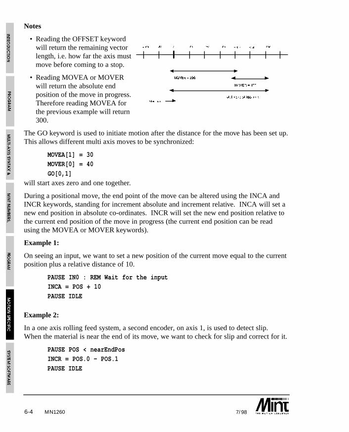
6-4 7/98
Notes
• Reading the OFFSET keywordwill return the remaining vectorlength, i.e. how far the axis mustmove before coming to a stop.
• Reading MOVEA or MOVERwill return the absolute endposition of the move in progress.Therefore reading MOVEA forthe previous example will return300.
The GO keyword is used to initiate motion after the distance for the move has been set up.This allows different multi axis moves to be synchronized:
MOVEA[1] = 30MOVER[0] = 40
GO[0,1]
will start axes zero and one together.
During a positional move, the end point of the move can be altered using the INCA andINCR keywords, standing for increment absolute and increment relative. INCA will set anew end position in absolute co-ordinates. INCR will set the new end position relative tothe current end position of the move in progress (the current end position can be readusing the MOVEA or MOVER keywords).
Example 1:
On seeing an input, we want to set a new position of the current move equal to the currentposition plus a relative distance of 10.
PAUSE IN0 : REM Wait for the inputINCA = POS + 10
PAUSE IDLE
Example 2:
In a one axis rolling feed system, a second encoder, on axis 1, is used to detect slip.When the material is near the end of its move, we want to check for slip and correct for it.
PAUSE POS < nearEndPosINCR = POS.0 - POS.1
PAUSE IDLE
MN1260
6-57/98
To use the above example, axis 1 must be put into either SERVOFF.1 (servo off) mode orturned off using CONFIG.1 = _off. This enables the encoder to read but not to generate afollowing error.
INCA and INCR cannot be used to change the end position of interpolated moves.
Reading the OFFSET keyword during a positional move will return the remaining movelength. For example:
MR = 200 : GO.0
? OFFSET
will return 200 i.e. the length of the move in operation.
MR = 200 : GO.0
PAUSE POS >= 170
? OFFSETwill return a value of approximately 30. Note that OFFSET always returns a positivenumber regardless of the direction of motion.
The OFFSET keyword is useful in indexing applications to determine how much of theindex is remaining. For example: in an indexing application, an output must be set 30mmbefore the end of the move where each index is 100mm in length:
LOOP
MOVER.1 = 100 : GO.1
PAUSE OFFSET.1 <= 30 : REM Wait for 30mm before endOUT1 = 1 : REM Set output
PAUSE IDLE.1 : REM Wait to stop
OUT1 = 0 : REM Clear output
ENDL
6.3.2 Interpolated Moves
The VECTORR/VECTORA and CIRCLER/CIRCLEA keywords provide interpolatedmotion on two/three orthogonal axes, for instance an X-Y table. These keywords arewrite only motion variables but are unique in that they always require at least two axes tobe specified. In interpolated moves, the axis speed and acceleration refer not to individualaxis speed, but to the path along which motion is in progress. Before initiating the move,it is important to ensure that the speed (SPEED), acceleration (ACCEL) and ramp factor(RAMP) on both axes are the same in terms of quad counts or steps and not scaled units(millimeters for example). This ensures that the velocity profiles on all axes stop at the
MN1260
6-6 7/98
same time (see section 6.3.5) Both axes should have the same line count/step rate forcorrect operation. For example:
SCALE = 100,200
SPEED = 20,20ACCEL = 1000,1000
the speed and acceleration are not the same in terms of quad counts or steps due to thescale factor.
SCALE = 100,200
SPEED = 40,20ACCEL = 2000,1000
is correct.
Note:
• Circular interpolation can only be performed on the first 2 axes (axes 0 and 1) of thecontroller.
• Both axes must have the same gear ratio and encoder line count for correct operation.In the case of circles, a gear ratio of 2:1 between X and Y for example will result in anellipse with an aspect ratio of 2:1. A circle cannot be drawn with different gear ratioson the motors.
6.3.3 Linear Interpolation
Two/three axis linear interpolation is executed with the keywords VECTORR andVECTORA, where VECTORR is a relative vector move, and VECTORA is an absolutevector move.
Example:
AXES[0,1]SPEED = 20;
VECTORA = 30,40 : GO
Executes an absolute linear interpolated move on orthogonal axes 0 and 1 at a speed of 20along the vector. After the AXES string and SPEED is set up, further moves require justthe VECTORR/VECTORA.
This differs from the command MOVEA:
SPEED = 20;MOVEA = 30,40 : GO
MN1260
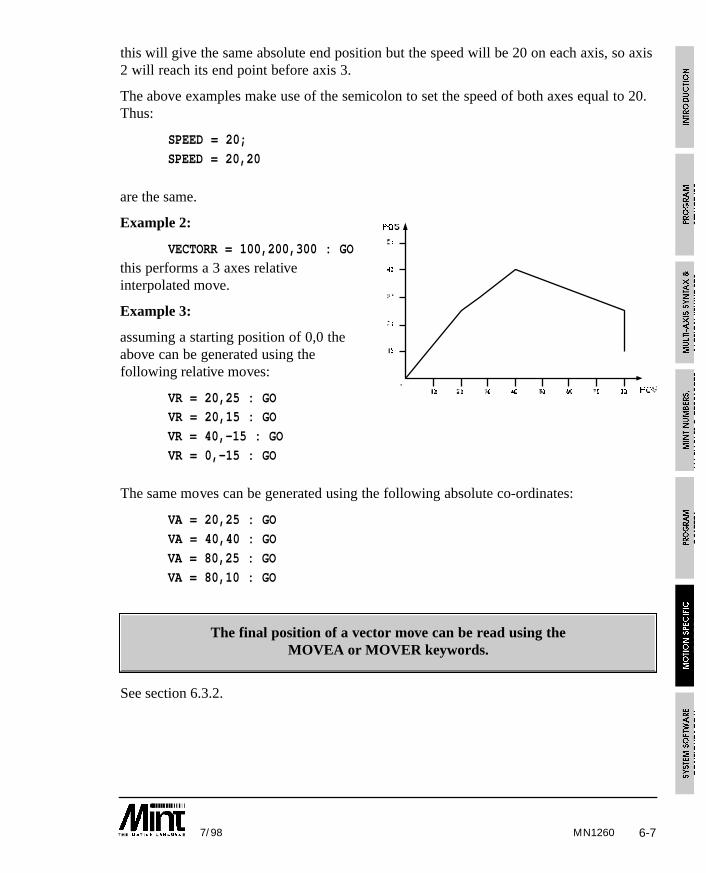
6-77/98
this will give the same absolute end position but the speed will be 20 on each axis, so axis2 will reach its end point before axis 3.
The above examples make use of the semicolon to set the speed of both axes equal to 20.Thus:
SPEED = 20;
SPEED = 20,20
are the same.
Example 2:
VECTORR = 100,200,300 : GO
this performs a 3 axes relativeinterpolated move.
Example 3:
assuming a starting position of 0,0 theabove can be generated using thefollowing relative moves:
VR = 20,25 : GOVR = 20,15 : GO
VR = 40,-15 : GO
VR = 0,-15 : GO
The same moves can be generated using the following absolute co-ordinates:
VA = 20,25 : GO
VA = 40,40 : GO
VA = 80,25 : GO
VA = 80,10 : GO
The final position of a vector move can be read using theMOVEA or MOVER keywords.
See section 6.3.2.
MN1260
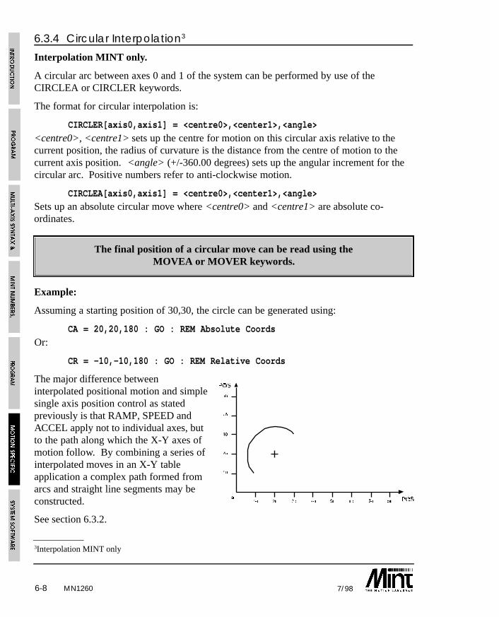
6-8 7/98
6.3.4 Circular Interpolation3
Interpolation MINT only.
A circular arc between axes 0 and 1 of the system can be performed by use of theCIRCLEA or CIRCLER keywords.
The format for circular interpolation is:
CIRCLER[axis0,axis1] = <centre0>,<center1>,<angle>
<centre0>, <centre1> sets up the centre for motion on this circular axis relative to thecurrent position, the radius of curvature is the distance from the centre of motion to thecurrent axis position. <angle> (+/-360.00 degrees) sets up the angular increment for thecircular arc. Positive numbers refer to anti-clockwise motion.
CIRCLEA[axis0,axis1] = <centre0>,<center1>,<angle>Sets up an absolute circular move where <centre0> and <centre1> are absolute co-ordinates.
The final position of a circular move can be read using theMOVEA or MOVER keywords.
Example:
Assuming a starting position of 30,30, the circle can be generated using:
CA = 20,20,180 : GO : REM Absolute Coords
Or:
CR = -10,-10,180 : GO : REM Relative Coords
The major difference betweeninterpolated positional motion and simplesingle axis position control as statedpreviously is that RAMP, SPEED andACCEL apply not to individual axes, butto the path along which the X-Y axes ofmotion follow. By combining a series ofinterpolated moves in an X-Y tableapplication a complex path formed fromarcs and straight line segments may beconstructed.
See section 6.3.2.
MN1260
3Interpolation MINT only
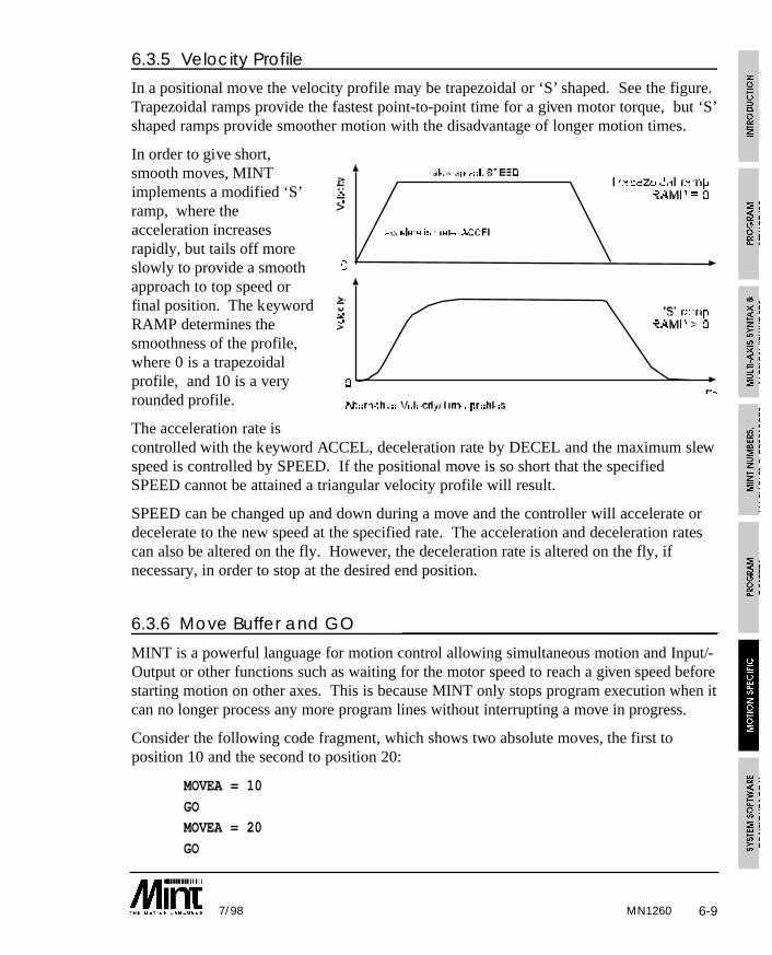
6-97/98
6.3.5 Velocity Profile
In a positional move the velocity profile may be trapezoidal or ‘S’ shaped. See the figure.Trapezoidal ramps provide the fastest point-to-point time for a given motor torque, but ‘S’shaped ramps provide smoother motion with the disadvantage of longer motion times.
In order to give short,smooth moves, MINTimplements a modified ‘S’ramp, where theacceleration increasesrapidly, but tails off moreslowly to provide a smoothapproach to top speed orfinal position. The keywordRAMP determines thesmoothness of the profile,where 0 is a trapezoidalprofile, and 10 is a veryrounded profile.
The acceleration rate iscontrolled with the keyword ACCEL, deceleration rate by DECEL and the maximum slewspeed is controlled by SPEED. If the positional move is so short that the specifiedSPEED cannot be attained a triangular velocity profile will result.
SPEED can be changed up and down during a move and the controller will accelerate ordecelerate to the new speed at the specified rate. The acceleration and deceleration ratescan also be altered on the fly. However, the deceleration rate is altered on the fly, ifnecessary, in order to stop at the desired end position.
6.3.6 Move Buffer and GO
MINT is a powerful language for motion control allowing simultaneous motion and Input/-Output or other functions such as waiting for the motor speed to reach a given speed beforestarting motion on other axes. This is because MINT only stops program execution when itcan no longer process any more program lines without interrupting a move in progress.
Consider the following code fragment, which shows two absolute moves, the first toposition 10 and the second to position 20:
MOVEA = 10
GOMOVEA = 20
GO
MN1260
6-10 7/98
MINT will encounter the first statement and immediately execute it, followed by GOwhich will start the move. (GO is used to start all positional moves). MINT nowencounters the next move statement and will set it up as the move pending on that axis.When MINT encounters the next GO statement it will identify that a move is already inprogress on the axis and wait, at this point therefore program execution will stop.
You can see that MINT is always one step ahead of the actual move in progress. Thisallows you to start a move on one axis and then execute other statements that might lookat inputs or execute other moves on other axes that start at a specified delay after the firstmove.
For example:
MOVEA = 100 : GO
PAUSE VEL > 20OUT1 = 1
will start a move on the axis and then wait until the velocity of that axis is greater than 20.After this is true then the program sets digital output one.
It is important that you should understand this concept because it is fundamental towriting MINT programs. There are some motion commands that are only valid when theaxis is not moving (in IDLE mode), these restrictions are noted against the specifickeywords in Section 10. For instance, acceleration cannot be adjusted during a positionalmove, therefore the code fragment:
MOVEA = 100 : GOACCEL = 200
will cause the program to abort with an error message:
ERROR: Motion in progress at line xx.
6.3.7 Contoured Moves
The keyword CONTON (Contouring On) allows a series of interpolated moves to beexecuted without decelerating at the end of each positional move. Thus the path is tracedout at a constant rate of motion.
Example:
SPEED = 20,20
CONTON
VECTORR = 40,40 : GOCIRCLER = 20,-20,-90 : GO
PAUSE IDLE[0,1] : REM Wait for axes to stop before
CONTOFF : REM Turning contouring off
MN1260

6-117/98
Assuming a starting position of 40,-20,this executes a straight line segment onaxes 0 and 1 followed by a circular arc of90 degrees at constant speed of 20. Notethat it is imperative to set the axis speedsand accelerations to the same value beforeexecuting the move since these refer tospeeds and accelerations along the vectorof motion.
The contouring routines maintain aconstant vector speed throughout the profile, deceleration will not occur until MINTdetects that the final vector has been reached. This gives rise to the following constraints:
• The speed must be low enough for the total deceleration phase to fit into the finalvector - otherwise the axes will come to an abrupt stop.
• Contouring should only be attempted around smooth shapes. Corners should berounded, a right angled corner will jar the machine since one axis mustinstantaneously stop and the other instantaneously start.
Contoured moves apply to the card as a whole. It is not possible to set-upcontoured moves on 2 axes and a normal positional move on the third axis.
Only the 2 axis contoured move can be executed.
6.4 Establishing a Datum
The HOME keyword is used to establish a datum position on the axis. This function isuseful for all applications that require a consistent zero point from which moves arereferenced. The HOME function should be incorporated at the beginning of the program,or in the configuration file. There are a number of alternative methods of establishing adatum that must be considered at the system design stage:
• In many applications (e.g. a linear table) the zero position may be defined by a limitswitch on the axis end stop or by a separate dedicated home switch that is placed at acentral point on the slide. If homing is to be performed on a limit switch, then thehome input must be connected to the limit input (see the hardware manual).
• The home position can be established on the basis of the opening of contacts on ahome switch, or on the first index pulse of the encoder after opening of the switch.The first method is quicker but less accurate than the second. However, the secondmethod requires a three channel encoder, with a separate marker (index) pulse.
MN1260

6-12 7/98MN1260
• With the controller, homing is always performed on the basis of a transition on thehome switch input from closed (connected to ground) to open circuit. For correctfunction of the HOME routine you must ensure that the home input is closed circuitwhen the function is called. Otherwise, the homing routine will immediatelyterminate.
6.4.1 Home Control WordThe use of an index pulse and direction of seek (positive or negative) that the systemmoves to find home is controlled by assigning a number to the homing routine as follows:
HOME[axes] = <home_control> {,<home_control> ...}
Where <home_control> is a binary number where bit zero, the least significant bit,determines index pulse usage and bit 1 determines positive or negative slew direction andbit 2 determines whether to home on the index pulse only for a rotary system. The binarynotation is shown in the table:
Home Control Word
Bit Number Action
0 1 to datum on home switch and seek index
1 1 to datum in a positive direction, 0 in a negative direction
2 1 to datum on the index pulse only
HOME values are:
Binary value Decimal Constant MeaningValue
0 0 _neg Negative seek, datum on switch
0001 1 _negindex Negative seek, datum on index
0010 2 _pos Positive seek, datum on switch
0011 3 _posindex Positive seek, datum on index
0100 4 4 Seek index pulse negative direction
0110 6 6 Seek index pulse positive direction
For instance, to perform homing on axis 1 in a positive direction with zero position as thefirst index pulse before limit switch closure, using binary notation:
HOME.1 = 011
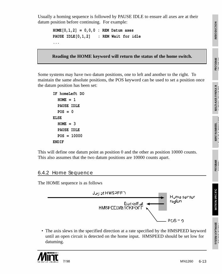
6-137/98
Usually a homing sequence is followed by PAUSE IDLE to ensure all axes are at theirdatum position before continuing. For example:
HOME[0,1,2] = 0,0,0 : REM Datum axes
PAUSE IDLE[0,1,2] : REM Wait for idle...
Reading the HOME keyword will return the status of the home switch.
Some systems may have two datum positions, one to left and another to the right. Tomaintain the same absolute positions, the POS keyword can be used to set a position oncethe datum position has been set:
IF homeLeft DO
HOME = 1
PAUSE IDLEPOS = 0
ELSE
HOME = 3
PAUSE IDLEPOS = 10000
ENDIF
This will define one datum point as position 0 and the other as position 10000 counts.This also assumes that the two datum positions are 10000 counts apart.
6.4.2 Home Sequence
The HOME sequence is as follows
• The axis slews in the specified direction at a rate specified by the HMSPEED keyworduntil an open circuit is detected on the home input. HMSPEED should be set low fordatuming.
MN1260
6-14 7/98
• The axis reverses and creeps at HMSPEED/BACKOFF until the switch input closesagain. BACKOFF is a user definable parameter.
• If home_control is configured to perform datum on switch, the position counter isreset to zero and the routine terminates.
• Otherwise, for datum on index, the axis continues at HMSPEED/BACKOFF until itdetects a transition on the index pulse. The axis stops, but because of the speed oftravel it will invariably overshoot. Therefore, the axis reverses again and creeps veryslowly back until it sees a transition on the index pulse. The position counter is thenreset to zero and the routine terminates.
Example:
HMSPEED = 200,200,200BACKOFF = 5,5,5
HOME = 1,1,1
PAUSE IDLE[0,1,2]
will set a datuming speed of 200 units/sec. When the home switch is seen, the axis willbackoff at a speed of 40 units/sec. For most applications you can leave backoff at itsdefault value of 10.
Function of the homing routine is very dependent on correct system installation, referenceshould be made to the hardware reference guide before attempting to use this facility.Establishing which direction is positive often requires a little careful experimentationduring system commissioning. This can be done simply by moving the axis manuallybackwards and forwards and reading the position. The following code can be used to dothis:
LOOP : ? POS; : BOL : ENDL
6.4.3 Order of Datuming
In most applications both axes are homed simultaneously for speed. For instance:
HOME.0 = 3
HOME.1 = 3
or:
HOME[0,1] = 3,3
or:
HM = 3;
executes simultaneous homing in a positive direction, on switch, for axes 0 and 1assuming AXES[0,1].
MN1260
6-157/98
Alternatively:
HOME = _posindex,_posindex
can be used.
In some applications there may be a requirement to datum one axis before the other toavoid mechanical obstructions. In order to achieve this you must include a PAUSE IDLEcommand between the two HOME commands:
HOME.0 = 3 : REM home axis zeroPAUSE IDLE.0 : REM wait for homing to finish on 0
HOME.1 = 3 : REM home axis one
If the limit switches are open circuit at any time other than during homing the drive unitwill cease to function and report a limit switch closure error. This is indicated by an ‘L’on the front panel status display and by the ERROR keyword which will return 3.
6.4.4 Defining a New Position
After the datum routine is complete, the zero position may be offset by performing apositional move and executing the keyword ZERO. This keyword zeros the positioncounter and establishes the current position as the new axis position.
A suggested code fragment for this is:
HOME.0 = 0 : REM execute homing routine (on switch)
MOVEA.0 = 20000:GO.0 : REM desired new home
PAUSE IDLE.0 : REM wait for end of moveZERO.0 : REM new zero position
It may be necessary to set a new datum position without actually moving the motor. Thiscan be achieved by using the POS keyword to set the position. For example:
HOME.0 = 0 : REM execute homing routine (on switch)
PAUSE IDLE.0 : REM wait for end of movePOS.0 = 10000 : REM Set new datum position to 10000
6.5 Pulse FollowingThe controller has a pulse and direction input that can be used to follow an external pulsetrain using the PULSE keyword. Pulse following is useful for master/slave typeapplications, or where the drive is intended to replace a stepper system, taking input froma stepper controller. The format is:
PULSE[axes] = <scaling factor> {,<scaling factor> ...}
MN1260

6-16 7/98MN1260
where the <scaling factor> is a number that determines the gear ratio between the pulseinput and the axis. Note that there is always a natural ratio of 2:1 since the controllercounts both the rising and falling edges of the pulse input. The gear ratio will also dependon the line density of the encoder.
PULSE = 1
will produce a movement of 2 quadrature counts on the encoder for a single pulse input(single pulse has 2 edges).
When pulse following is initiated it will ramp up to the incoming pulse speed (read usingPULSEVEL) at an acceleration rate defined by ACCEL.
The pulse input has an associated direction input which causes the pulse counter to countup or down. In many applications where you are following a machine which does notreverse, the common practice is to connect just one channel of the master encoder to thepulse input, which gives 2x multiplication by counting both rising and falling edges. Thedirection input should also be tied to either 5V or ground. It is also possible to interfaceboth channels of an incremental encoder by using an external quadrature decoder chipsuch as a Hewlett Packard 2016. This converts the A and B channels into a pulse anddirection signal. MINT also allows direct encoder following via one of the controllersencoder inputs. This is discussed in section 6.6.
Pulse following mode is terminated by the STOP command or by assigning 0 to PULSE.
Example 2:
PULSE = 2.5, -1will produce a movement of 5 counts on the motor for a single pulse input on the firstaxis, and a movement of 2 counts per pulse input on the second axis but in the oppositedirection.
There are various keywords associated with pulse following. These are:
Keyword Action
OFFSET/OF Perform an offset on the base speed
PULSEVEL/PV Velocity of pulse train
TIMER/TI Read timer (pulse follower input)
WRAP/WR Set reset value of timer
Using the reset counter input on the controller, a marker pulse on an encoder can be usedto reset the internal pulse timer every revolution of the encoder. The maximum number ofcounts received from the encoder will therefore be:
line count x 2
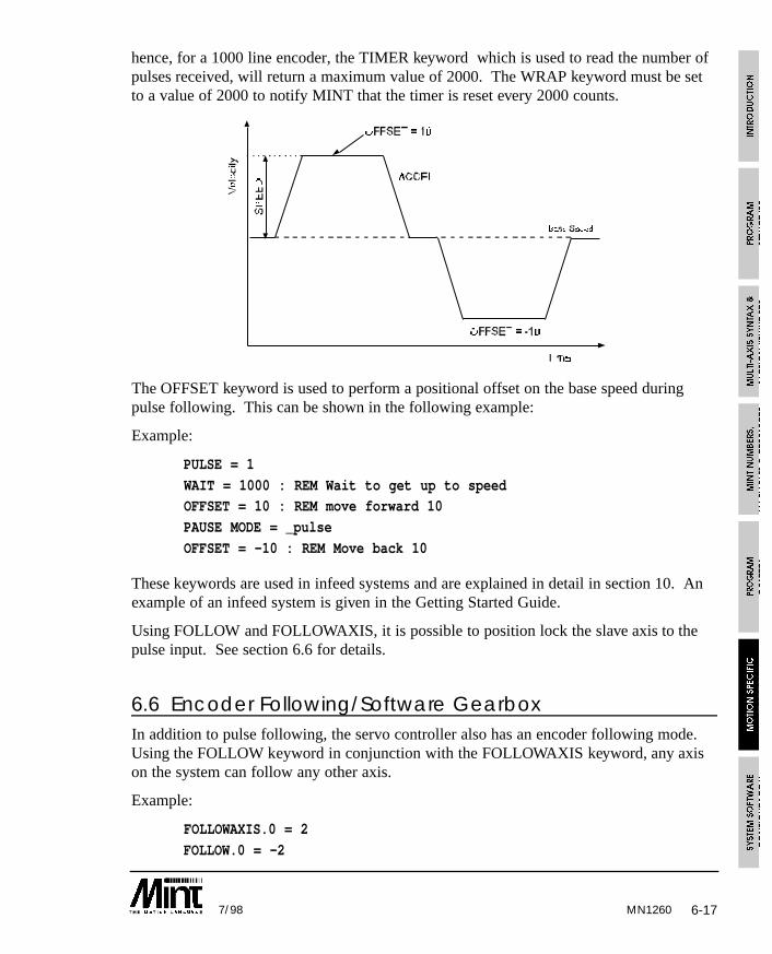
6-177/98
hence, for a 1000 line encoder, the TIMER keyword which is used to read the number ofpulses received, will return a maximum value of 2000. The WRAP keyword must be setto a value of 2000 to notify MINT that the timer is reset every 2000 counts.
The OFFSET keyword is used to perform a positional offset on the base speed duringpulse following. This can be shown in the following example:
Example:
PULSE = 1
WAIT = 1000 : REM Wait to get up to speedOFFSET = 10 : REM move forward 10
PAUSE MODE = _pulse
OFFSET = -10 : REM Move back 10
These keywords are used in infeed systems and are explained in detail in section 10. Anexample of an infeed system is given in the Getting Started Guide.
Using FOLLOW and FOLLOWAXIS, it is possible to position lock the slave axis to thepulse input. See section 6.6 for details.
6.6 Encoder Following/Software GearboxIn addition to pulse following, the servo controller also has an encoder following mode.Using the FOLLOW keyword in conjunction with the FOLLOWAXIS keyword, any axison the system can follow any other axis.
Example:
FOLLOWAXIS.0 = 2
FOLLOW.0 = -2
MN1260
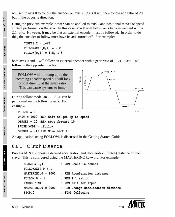
6-18 7/98
will set up axis 0 to follow the encoder on axis 2. Axis 0 will then follow at a ratio of 2:1but in the opposite direction.
Using the previous example, power can be applied to axis 2 and positional moves or speedcontrol performed on the axis. In this case, axis 0 will follow axis twos movement with a2:1 ratio. However, it may be that an external encoder must be followed. In order to dothis, the encoder to follow must have its axis turned off. For example:
CONFIG.2 = _off
FOLLOWAXIS[0,1] = 2,2FOLLOW[0,1] = 1.5,-1.5
both axes 0 and 1 will follow an external encoder with a gear ratio of 1.5:1. Axis 1 willfollow in the opposite direction.
FOLLOW will not ramp up to theincoming encoder speed but will lock
onto it directly at the given ratio.This can cause systems to jump.
During follow mode, an OFFSET can beperformed on the following axis. Forexample:
FOLLOW = 1WAIT = 1000 :REM Wait to get up to speed
OFFSET = 10 :REM move forward 10
PAUSE MODE = _follow
OFFSET = -10:REM Move back 10
An application, using FOLLOW, is discussed in the Getting Started Guide.
6.6.1 Clutch DistanceProcess MINT supports a defined acceleration and deceleration (clutch) distance on theslave. This is configured using the MASTERINC keyword. For example:
SCALE = 1,1 : REM Scale in counts
FOLLOWAXIS.0 = 1MASTERINC.0 = 1000 : REM Acceleration distance
FOLLOW.0 = 1 : REM 1:1 ratio
PAUSE !IN1 : REM Wait for input
MASTERINC.0 = 2000 : REM Change deceleration distanceSTOP.0 : STOP following
MN1260
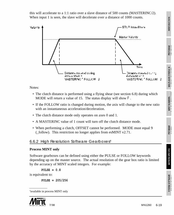
6-197/98
this will accelerate to a 1:1 ratio over a slave distance of 500 counts (MASTERINC/2).When input 1 is seen, the slave will decelerate over a distance of 1000 counts.
Notes:
• The clutch distance is performed using a flying shear (see section 6.8) during whichMODE will return a value of 15. The status display will show F .
• If the FOLLOW ratio is changed during motion, the axis will change to the new ratiowith an instantaneous acceleration/deceleration.
• The clutch distance mode only operates on axes 0 and 1.
• A MASTERINC value of 1 count will turn off the clutch distance mode.
• When performing a clutch, OFFSET cannot be performed. MODE must equal 9(_follow). This restriction no longer applies from esMINT v2.71.
6.6.2 High Resolution Software Gearboxes4
Process MINT only
Software gearboxes can be defined using either the PULSE or FOLLOW keywordsdepending up on the master source. The actual resolution of the gear box ratio is limitedby the accuracy of MINT scaled integers. For example:
PULSE = 0.8
is equivalent to:
PULSE = 205/256
MN1260
4available in process MINT only
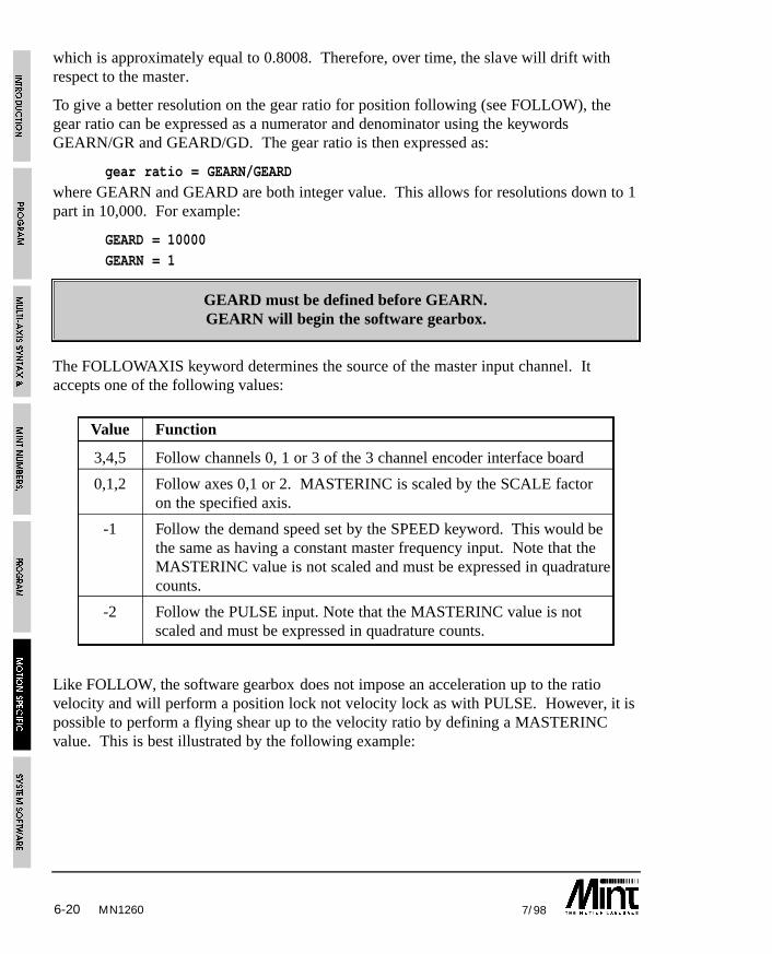
6-20 7/98
which is approximately equal to 0.8008. Therefore, over time, the slave will drift withrespect to the master.
To give a better resolution on the gear ratio for position following (see FOLLOW), thegear ratio can be expressed as a numerator and denominator using the keywordsGEARN/GR and GEARD/GD. The gear ratio is then expressed as:
gear ratio = GEARN/GEARD
where GEARN and GEARD are both integer value. This allows for resolutions down to 1part in 10,000. For example:
GEARD = 10000GEARN = 1
GEARD must be defined before GEARN.GEARN will begin the software gearbox.
The FOLLOWAXIS keyword determines the source of the master input channel. Itaccepts one of the following values:
Value Function
3,4,5 Follow channels 0, 1 or 3 of the 3 channel encoder interface board
0,1,2 Follow axes 0,1 or 2. MASTERINC is scaled by the SCALE factoron the specified axis.
-1 Follow the demand speed set by the SPEED keyword. This would bethe same as having a constant master frequency input. Note that theMASTERINC value is not scaled and must be expressed in quadraturecounts.
-2 Follow the PULSE input. Note that the MASTERINC value is notscaled and must be expressed in quadrature counts.
Like FOLLOW, the software gearbox does not impose an acceleration up to the ratiovelocity and will perform a position lock not velocity lock as with PULSE. However, it ispossible to perform a flying shear up to the velocity ratio by defining a MASTERINCvalue. This is best illustrated by the following example:
MN1260

6-217/98
SCALE = 1,1 : REM Scale in countsFOLLOWAXIS.0 = -2
MASTERINC.0 = 1000 : REM Acceleration distance
GEARD = 10
GEARN = 2 : REM Follow ratio of 0.2PAUSE !IN1 : REM Wait for input
MASTERINC.0 = 2000 : REM Change deceleration distance
STOP.0 : STOP following
Notes:
• The clutch distance is performed using a flying shear (see section 6.8) during whichMODE will return a value of 15. The status display will show F .
• Once a gear ratio has been set up, the ratio cannot be changed on the fly unlikePULSE and FOLLOW. A “motion in progress error” will occur.
• The software gearbox only applies to axes 0 and 1.
• A MASTERINC value of 1 count will turn off the clutch distance mode.
• When performing a clutch, OFFSET cannot be performed. MODE must equal 18.This restriction no longer applies from esMINT v2.71.
MN1260
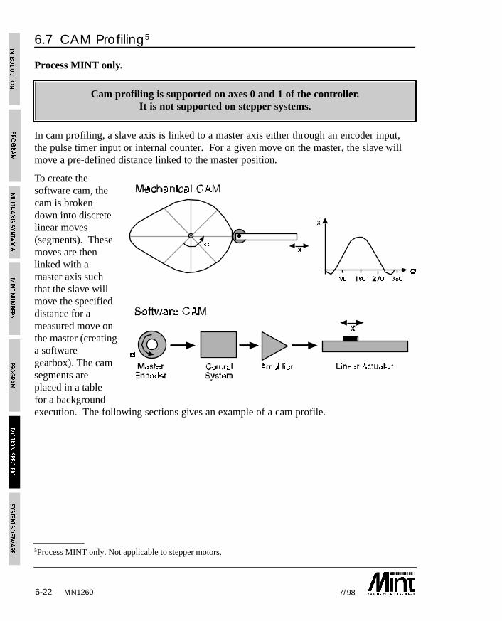
6-22 7/98
6.7 CAM Profiling5
Process MINT only.
Cam profiling is supported on axes 0 and 1 of the controller.It is not supported on stepper systems.
In cam profiling, a slave axis is linked to a master axis either through an encoder input,the pulse timer input or internal counter. For a given move on the master, the slave willmove a pre-defined distance linked to the master position.
To create thesoftware cam, thecam is brokendown into discretelinear moves(segments). Thesemoves are thenlinked with amaster axis suchthat the slave willmove the specifieddistance for ameasured move onthe master (creatinga softwaregearbox). The camsegments areplaced in a tablefor a backgroundexecution. The following sections gives an example of a cam profile.
MN1260
5Process MINT only. Not applicable to stepper motors.
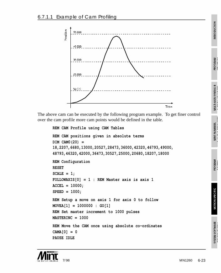
6-237/98
6.7.1.1 Example of Cam Profiling
The above cam can be executed by the following program example. To get finer controlover the cam profile more cam points would be defined in the table.
REM CAM Profile using CAM Tables
REM CAM positions given in absolute terms
DIM CAM0(20) =18,2207,6680,13000,20527,28473,36000,42320,46793,49000,
48793,46320,42000,36473,30527,25000,20680,18207,18000
REM Configuration
RESETSCALE = 1;
FOLLOWAXIS[0] = 1 : REM Master axis is axis 1
ACCEL = 10000;
SPEED = 1000;
REM Setup a move on axis 1 for axis 0 to followMOVEA[1] = 1000000 : GO[1]
REM Set master increment to 1000 pulses
MASTERINC = 1000
REM Move the CAM once using absolute co-ordinates
CAMA[0] = 0PAUSE IDLE
MN1260
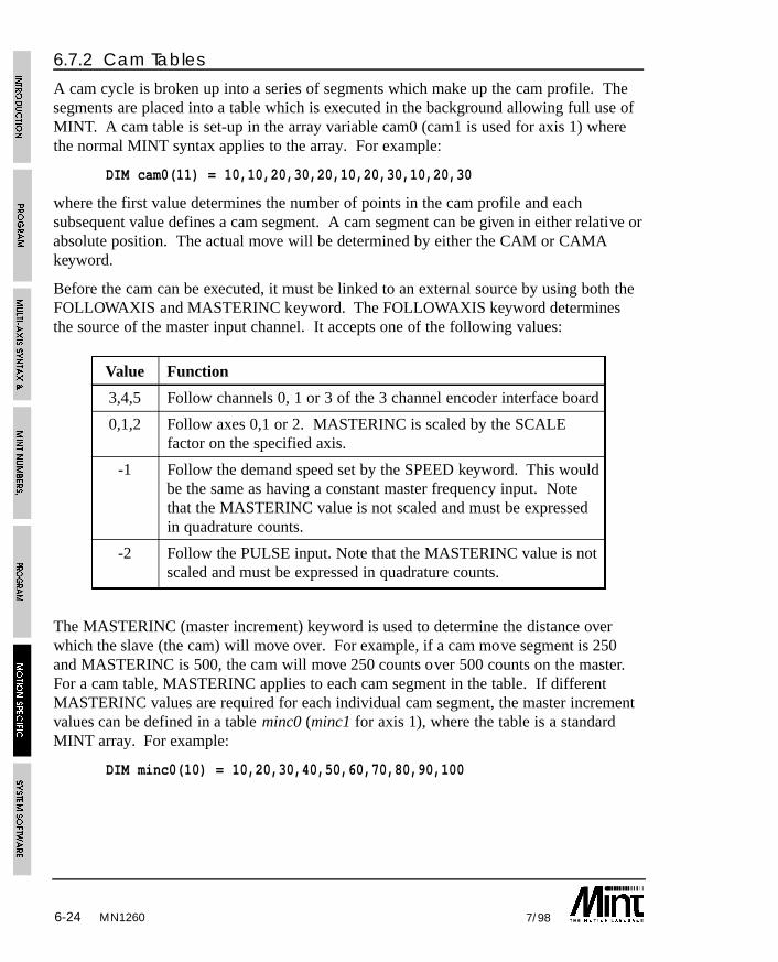
6-24 7/98MN1260
6.7.2 Cam Tables
A cam cycle is broken up into a series of segments which make up the cam profile. Thesegments are placed into a table which is executed in the background allowing full use ofMINT. A cam table is set-up in the array variable cam0 (cam1 is used for axis 1) wherethe normal MINT syntax applies to the array. For example:
DIM cam0(11) = 10,10,20,30,20,10,20,30,10,20,30
where the first value determines the number of points in the cam profile and eachsubsequent value defines a cam segment. A cam segment can be given in either relative orabsolute position. The actual move will be determined by either the CAM or CAMAkeyword.
Before the cam can be executed, it must be linked to an external source by using both theFOLLOWAXIS and MASTERINC keyword. The FOLLOWAXIS keyword determinesthe source of the master input channel. It accepts one of the following values:
Value Function
3,4,5 Follow channels 0, 1 or 3 of the 3 channel encoder interface board
0,1,2 Follow axes 0,1 or 2. MASTERINC is scaled by the SCALEfactor on the specified axis.
-1 Follow the demand speed set by the SPEED keyword. This wouldbe the same as having a constant master frequency input. Notethat the MASTERINC value is not scaled and must be expressedin quadrature counts.
-2 Follow the PULSE input. Note that the MASTERINC value is notscaled and must be expressed in quadrature counts.
The MASTERINC (master increment) keyword is used to determine the distance overwhich the slave (the cam) will move over. For example, if a cam move segment is 250and MASTERINC is 500, the cam will move 250 counts over 500 counts on the master.For a cam table, MASTERINC applies to each cam segment in the table. If differentMASTERINC values are required for each individual cam segment, the master incrementvalues can be defined in a table minc0 (minc1 for axis 1), where the table is a standardMINT array. For example:
DIM minc0(10) = 10,20,30,40,50,60,70,80,90,100
6-257/98
Notes on cam and minc tables:
• The first element in the cam table defines the number of cam segments. Allsubsequent values define the cam segments. This allows variable length cam tables tobe defined with ease.
• The values given in the minc0 array are defined as quad counts whereas the valuesgiven in the cam0 array are scaled by the scale factor, SCALE.
• The number of points in the minc table is given by the number of points in the camtable. The first element in the minc table is not used to define the number of movesegments.
• Master positions in the minc table are defined in relative terms.
• A cam segment must be defined to take no less than 4ms to execute (given a 2ms loopclosure time).
The keywords CAM and CAMA are used to start a cam profile on a cam table (cam0 orcam1). The CAM keyword defines all the values in the table as relative moves whereasCAMA treats all the values as absolute moves. For example:
CAM.0 = 0
will execute a cam for axis 0 on the cam table cam0. The cam will finish when the lastcam point has been executed.
CAM.1 = 1
will execute a cam for axis 1 on the cam table cam1. The cam will execute indefinitely.Once the last cam segment has been executed, the cam motion will begin again.
To execute a cam using absolute values in the table, use the CAMA command in the sameway as the cam command.
An absolute cam only defines absolute positions within one cam cycle and notto an absolute motor position. An absolute cam always assumes a starting
position of zero. Defining zero as the first cam segment will result in the camwaiting for the Master Increment length.
MN1260

6-26 7/98MN1260
The value passed to CAMA and CAM will determine their action. Any of the followingvalues are accepted:
CAM FunctionValue
0 One shot cam
1 Continuous cam. Cam table restarts when end is reached
2 One shot cam triggered by a fast interrupt.
3 Continuous cam. Triggered by a fast interrupt.Successive fast interrupts will reset the cam.
+4 Adding 4 to the CAMA keyword will reference all absolutepositions to the motor position and not the cam.
Stopping a continuous cam at the end if its profile can be achieved by setting up a oneshot cam as follows:
CAMA = 1 : REM Continuous cam
PAUSE IN1 : REM Wait for input 1CAMA = 0 : REM Finish current cam, execute next cam and then stop.
alternatively:
CAMA = 1 : REM continuous cam
PAUSE IN1 : REM Wait for an inputPAUSE CAMINDEX = maxIndex : STOP
this will stop when the last cam index has been executed without executing an extra camprofile.
Notes on cam profiling:
• The master must be moving in one direction only.
• The cam will move in the direction defined by the cam segment regardless of themaster direction.
6-277/98
6.7.3 Synchronizing Cams with the Fast Interrupt
A cam movement can be synchronized with the fast interrupt. This can be set-up as eithera one shot or a continuous cam that is reset on every fast interrupt. This is achieved byusing the CAM or CAMA keyword as follows:
CAM = 2
This will enable a one shot cam by waiting for the fast interrupt before starting the cam.Once the cam has executed, the mode will return to idle. Any subsequent fast interruptswill start the cam again. If a fast interrupt occurs during the cam motion, the cam willreset and begin again. Use the STOP command to terminate a one shot cam.
CAM = 3
will enable a continuous cam that begins on a fast interrupt. If a fast interrupt occursduring the cam motion, the cam will reset and begin again.
In both cases, the cam will begin within 2ms of the fast interrupt.
The cam should only be synchronized with the fast interrupt when the cam speedapproaches zero, otherwise a glitch in the cam profile may be noted.
TRIGGER can be used to synchronize the cam with a digital input (IN0 .. IN7). Seesection 6.9 for details.
6.7.4 Multiple Cam Tables
Multiple cam tables can be defined using the CAMSTART and CAMEND keywordswhich define the start and end points for a Cam table. The first element in the cam tableis still used to define the number of elements in the cam, but if a value of zero is given,the cam table will execute all points up to CAMEND. The starting cam segment will bedefined by the CAMSTART keyword. For example:
CAMSTART = 10
CAMEND = 20
DIM cam0(21) = 0,10,20,30,40,50,60,70,80,90,100,
100,90,80,70,60,50,40,30,20,10
When the cam is started using either the CAM or CAMA keyword, the cam segments 10to 20 are executed.
Note that it is assumed that the first element has an array index value of 0, and the camsegment values start at 1. The actual start cam segment value will be given by:
v = cam0(CAMSTART + 1)
MN1260
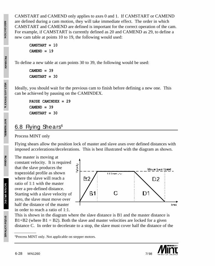
6-28 7/98
CAMSTART and CAMEND only applies to axes 0 and 1. If CAMSTART or CAMENDare defined during a cam motion, they will take immediate effect. The order in whichCAMSTART and CAMEND are defined is important for the correct operation of the cam.For example, if CAMSTART is currently defined as 20 and CAMEND as 29, to define anew cam table at points 10 to 19, the following would used:
CAMSTART = 10
CAMEND = 19
To define a new table at cam points 30 to 39, the following would be used:
CAMEND = 39
CAMSTART = 30
Ideally, you should wait for the previous cam to finish before defining a new one. Thiscan be achieved by pausing on the CAMINDEX.
PAUSE CAMINDEX = 29
CAMEND = 39
CAMSTART = 30
6.8 Flying Shears6
Process MINT only
Flying shears allow the position lock of master and slave axes over defined distances withimposed accelerations/decelerations. This is best illustrated with the diagram as shown.
The master is moving atconstant velocity. It is requiredthat the slave produces thetrapezoidal profile as shownwhere the slave will reach aratio of 1:1 with the masterover a pre-defined distance.Starting with a slave velocity ofzero, the slave must move overhalf the distance of the masterin order to reach a ratio of 1:1.This is shown in the diagram where the slave distance is B1 and the master distance isB1+B2 (where B1 = B2). Both the slave and master velocities are locked for a givendistance C. In order to decelerate to a stop, the slave must cover half the distance of the
MN1260
6Process MINT only. Not applicable on stepper motors.
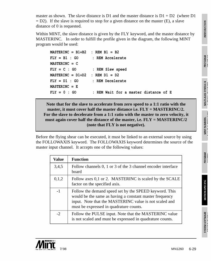
6-297/98
master as shown. The slave distance is D1 and the master distance is D1 + D2 (where D1= D2). If the slave is required to stop for a given distance on the master (E), a slavedistance of 0 is requested.
Within MINT, the slave distance is given by the FLY keyword, and the master distance byMASTERINC. In order to fulfill the profile given in the diagram, the following MINTprogram would be used:
MASTERINC = B1+B2 : REM B1 = B2
FLY = B1 : GO : REM AccelerateMASTERINC = C
FLY = C : GO : REM Slew speed
MASTERINC = D1+D2 : REM D1 = D2
FLY = D1 : GO : REM DecelerateMASTERINC = E
FLY = 0 : GO : REM Wait for a master distance of E
Note that for the slave to accelerate from zero speed to a 1:1 ratio with themaster, it must cover half the master distance i.e. FLY = MASTERINC/2.
For the slave to decelerate from a 1:1 ratio with the master to zero velocity, itmust again cover half the distance of the master, i.e. FLY = MASTERINC/2
(note that FLY is not negative).
Before the flying shear can be executed, it must be linked to an external source by usingthe FOLLOWAXIS keyword. The FOLLOWAXIS keyword determines the source of themaster input channel. It accepts one of the following values:
Value Function
3,4,5 Follow channels 0, 1 or 3 of the 3 channel encoder interfaceboard
0,1,2 Follow axes 0,1 or 2. MASTERINC is scaled by the SCALEfactor on the specified axis.
-1 Follow the demand speed set by the SPEED keyword. Thiswould be the same as having a constant master frequencyinput. Note that the MASTERINC value is not scaled andmust be expressed in quadrature counts.
-2 Follow the PULSE input. Note that the MASTERINC valueis not scaled and must be expressed in quadrature counts.
MN1260
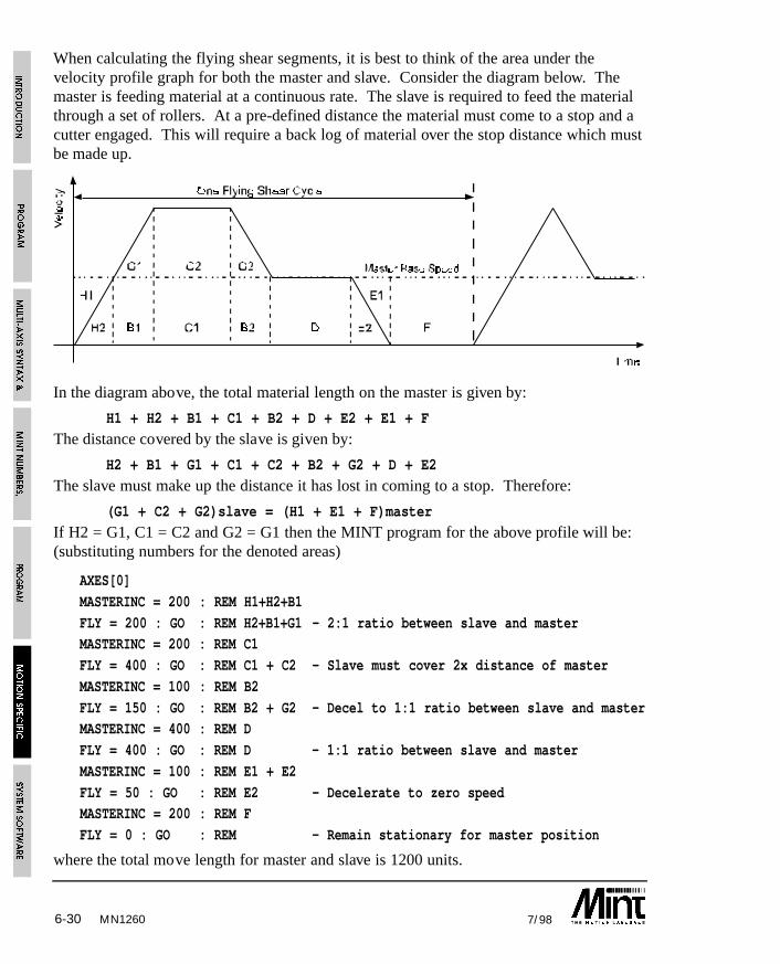
6-30 7/98
When calculating the flying shear segments, it is best to think of the area under thevelocity profile graph for both the master and slave. Consider the diagram below. Themaster is feeding material at a continuous rate. The slave is required to feed the materialthrough a set of rollers. At a pre-defined distance the material must come to a stop and acutter engaged. This will require a back log of material over the stop distance which mustbe made up.
In the diagram above, the total material length on the master is given by:
H1 + H2 + B1 + C1 + B2 + D + E2 + E1 + F
The distance covered by the slave is given by:
H2 + B1 + G1 + C1 + C2 + B2 + G2 + D + E2
The slave must make up the distance it has lost in coming to a stop. Therefore:
(G1 + C2 + G2)slave = (H1 + E1 + F)master
If H2 = G1, C1 = C2 and G2 = G1 then the MINT program for the above profile will be:(substituting numbers for the denoted areas)
AXES[0]
MASTERINC = 200 : REM H1+H2+B1
FLY = 200 : GO : REM H2+B1+G1 - 2:1 ratio between slave and masterMASTERINC = 200 : REM C1
FLY = 400 : GO : REM C1 + C2 - Slave must cover 2x distance of master
MASTERINC = 100 : REM B2
FLY = 150 : GO : REM B2 + G2 - Decel to 1:1 ratio between slave and masterMASTERINC = 400 : REM D
FLY = 400 : GO : REM D - 1:1 ratio between slave and master
MASTERINC = 100 : REM E1 + E2
FLY = 50 : GO : REM E2 - Decelerate to zero speedMASTERINC = 200 : REM F
FLY = 0 : GO : REM - Remain stationary for master position
where the total move length for master and slave is 1200 units.
MN1260
6-317/98
Notes on Flying Shears
• 10 milli-seconds should be allowed in order to set-up a flying shear segment, where aflying shear segment is defined as a FLY/MASTERINC combination.
• The master position must be uni-directional.
• The slave (fly) will move on the direction defined by the FLY keyword regardless ofthe direction of the master. In order to move the slave backwards, the negative FLYmust be given.
• From esMINT v2.71, an OFFSET move can be placed on a FLY (or multiple FLY)segments.
6.8.1 Example of a Flying ShearA common problem in industrial automation is to perform an operation on a continuouslymoving web, extrusion, or other material which is generated by a continuous productionprocess. Examples of this type of operation are cropping metal produced from a rollingmill, slitting plastic bags across their width or placing labels on a backing strip.
Each application has the common requirement that the operation must be performed at aregular distance on the moving web. The usual method of achieving this is to use a linearslide which moves forward in synchronism with the web during the operation and returnsquickly to datum before commencing the next operation.
At a programmable count the controller causes the servo motor to accelerate to web speedbefore turning on an output that causes the shear to operate. The servo motor thendecelerates to a stop and reverses to return the slide to the start position. The velocity ofthe linear slide with respect to the position of the web for one cycle is shown on thefigure. This profile is repeated for each operation on the web.
The FLY keyword in MINT is used to perform this velocity profile. The FLY functionallows the position of the slave axis to be specified with respect to the position of a masteraxis so that the two are locked together.
This is analogous to a mechanical cam and push rod assembly, the major advantage beingthat the software system is mechanically simpler and can be changed (i.e. different lengthsof cut) at the press of a button. The controller can also synchronize other machinefunctions in a similar way to a PLC and keep track of the total amount of material cut etc.,which can be displayed on an operator message panel.
The following MINT program specifies each movement segment in terms of the distanceto be moved on the linear slide for a given distance on the master encoder. The shear andproduct are therefore always in correct synchronism even if the speed of the product variesthroughout a cycle.
MN1260
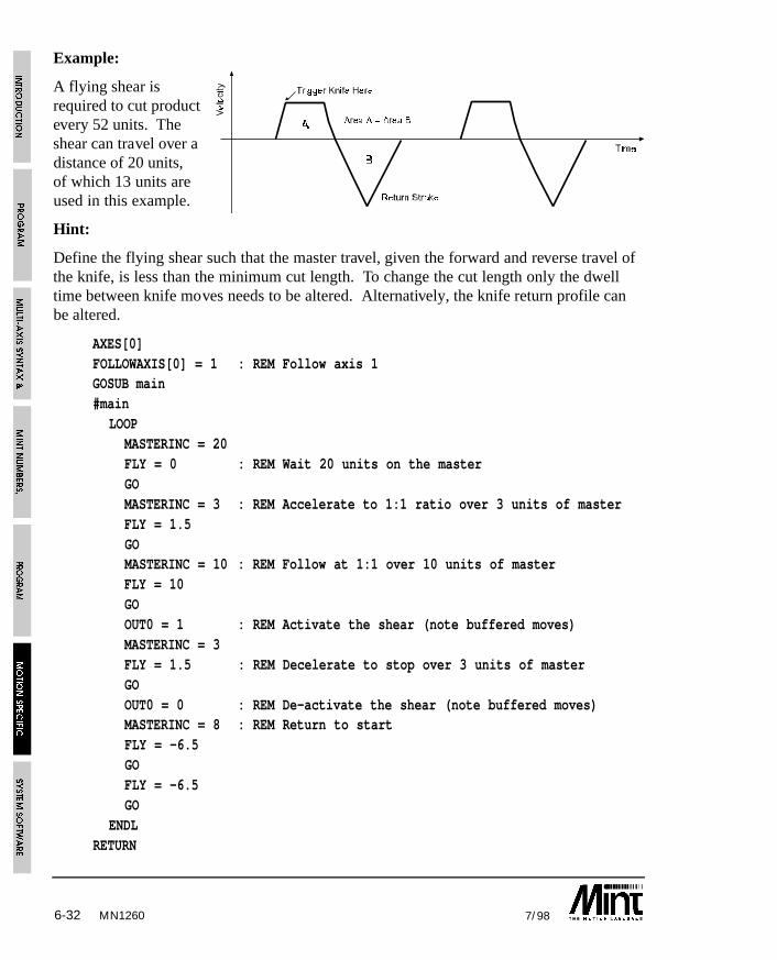
6-32 7/98
Example:
A flying shear isrequired to cut productevery 52 units. Theshear can travel over adistance of 20 units,of which 13 units areused in this example.
Hint:
Define the flying shear such that the master travel, given the forward and reverse travel ofthe knife, is less than the minimum cut length. To change the cut length only the dwelltime between knife moves needs to be altered. Alternatively, the knife return profile canbe altered.
AXES[0]FOLLOWAXIS[0] = 1 : REM Follow axis 1GOSUB main#main
LOOPMASTERINC = 20FLY = 0 : REM Wait 20 units on the masterGOMASTERINC = 3 : REM Accelerate to 1:1 ratio over 3 units of masterFLY = 1.5GOMASTERINC = 10 : REM Follow at 1:1 over 10 units of masterFLY = 10GOOUT0 = 1 : REM Activate the shear (note buffered moves)MASTERINC = 3FLY = 1.5 : REM Decelerate to stop over 3 units of masterGOOUT0 = 0 : REM De-activate the shear (note buffered moves)MASTERINC = 8 : REM Return to startFLY = -6.5GOFLY = -6.5GO
ENDLRETURN
MN1260

6-337/98
Note the placement of the OUT0 statements. These appear to occur at the wrong flysegment, however, due to the nature of MINT with buffered moves, it is necessary to placethe OUT0 statement after the fly segment following the segment where you require thecommand to be performed. For example:
FLY = 10 : GO
OUT2 = 1 : REM Executed immediately, before FLY = 10 has completed ie: REM when FLY = 10 starts
FLY = 20 : GO
OUT1 = 1 : REM Executed when FLY = 20 has started, ie when FLY=10
: REM has finished
The total movement of the material is given by:
20 + 3 + 10 + 3 + 8 + 8 = 52
The first cut will however be short by 29 units, since the shear will cut at 20 + 3 units.
The shear moves 1.5 units to accelerate to a ratio of 1:1, moves 10 units with the materialand decelerates over 1.5 units, giving a total distance on the slave of 13 units.
Note that to ramp up to a ratio of 1:1, the ratio of MASTERINC to FLY is 2:1.
6.9 Triggered Moves
Process MINT only
The TRIGGER keyword allows a move to be defined but not executed until an input goeslow. TRIGGER uses the syntax as shown:
TRIGGER.axis = <input channel>
For example:
TRIGGER.2 = 1
MOVEA.2 = 100 : GO.2
When input 1 goes low, axis 2 will move to position 100. This replaces the followingcode:
#IN1
MOVEA.2 = 100 : GO.2RETURN
The advantage of using TRIGGER over an interrupt, is that the move is guaranteed to startwithin 1 servo cycle (2ms typically).
MN1260
6-34 7/98
TRIGGER applies to all move types: CAM, CAMS, FOLLOW, GEARN/GEARD, JOG,MOVEA, MOVER, OFFSET, PULSE.
Example 2:
MASTERINC.0 = 100
GEARD.0 = 15TRIGGER.0 = 7
GEARN.0 = 1
will begin a high resolution gearbox in input 7.
Reading the TRIGGER keyword will return the mode of motion (see section 6.10) whichis awaiting the trigger signal. If no move is awaiting a trigger signal, it will return -1.
A move can be triggered of the fast interrupt using a TRIGGER value of 8. If a CAM,FOLLOW or FLY is triggered off the fast interrupt, the distance covered by the masterfrom the time the position was latched to the point where the move starts is taken intoaccount.
A triggered move can be masked off using the IMASK keyword. For example:
IMASK = IMASK AND 0011
TRIGGER.0 = 2
MOVEA = 0 : GO
When the input goes low, the triggered move will be held pending until the appropriate bitin IMASK (bit 2 in the example) is set.
IMASK = IMASK OR 0100IPEND can be used to clear down the trigger event.
6.10 Mode of MotionDuring positional, speed or torque control, the mode of motion can be interrogated usingthe MODE keyword. The MODE values are given in the keyword section under MODE.
This keyword is primarily useful for detecting when a positional move is complete, sincethe MODE will always return to zero at this point. Imagine that you wish to set outputone after the finish of a relative move:
MOVER = 150 : GO : REM mode is set to 2
PAUSE MODE = 0 : REM wait for motion to finish
OUT1 = 1 : REM set output one
MN1260
6-357/98
Alternatively:
PAUSE MODE = 0
can be replaced by:
PAUSE IDLE
Example 2:
PAUSE MODE.0 = 0 AND MODE.1 = 0
can be replaced by:
PAUSE IDLE[0,1]
Example 3:
PULSE = 1 : REM Pulse following mode at ratio of 1:1
LOOP
PAUSE IN1 : REM Wait for a falling edge on input 1
PAUSE !IN1REM Perform a positional offset on seeing the input
REM signal
OFFSET = offsetValue
REM Wait for offset to finishPAUSE MODE = _pulse
ENDL
this will follow an incoming pulse train and perform a positional offset on seeing digitalinput 1. The use of “PAUSE MODE = _pulse” will wait for the offset to finish execution.
The 7 segment status display also indicates the mode of motion. Section 8.3 covers this indetail.
6.11 Digital Input/Output
The controller has 8 general purpose digital inputs and 8 general purpose digital outputsthat are software controlled from MINT. The keywords IN and OUT are used to read andwrite to the I/O. Alternatively, interrupts can be set-up on the inputs using the #INxsubroutines (see section 5.3.2).
MN1260
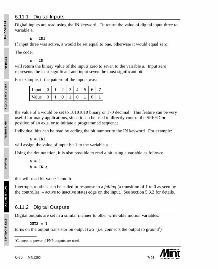
6-36 7/98MN1260
7Connect to power if PNP outputs are used.
6.11.1 Digital Inputs
Digital inputs are read using the IN keyword. To return the value of digital input three tovariable a:
a = IN3
If input three was active, a would be set equal to one, otherwise it would equal zero.
The code:
a = IN
will return the binary value of the inputs zero to seven to the variable a. Input zerorepresents the least significant and input seven the most significant bit.
For example, if the pattern of the inputs was:
Input 0 1 2 3 4 5 6 7
Value 0 1 0 1 0 1 0 1
the value of a would be set to 10101010 binary or 170 decimal. This feature can be veryuseful for many applications, since it can be used to directly control the SPEED orposition of an axis, or to initiate a programmed sequence.
Individual bits can be read by adding the bit number to the IN keyword. For example:
a = IN1
will assign the value of input bit 1 to the variable a.
Using the dot notation, it is also possible to read a bit using a variable as follows:
a = 1
b = IN.a
this will read bit value 1 into b.
Interrupts routines can be called in response to a falling (a transition of 1 to 0 as seen bythe controller – active to inactive state) edge on the input. See section 5.3.2 for details.
6.11.2 Digital Outputs
Digital outputs are set in a similar manner to other write-able motion variables:
OUT2 = 1
turns on the output transistor on output two (i.e. connects the output to ground7)
6-377/98
Outputs zero to seven may be set simultaneously by the use of the OUT keyword, thisworks in a similar manner to the IN keyword, the outputs are set to the digital value of thenumber or variable assigned to them.
If a number greater than 255 is written to the outputs, an error is generated and thefollowing message is printed:
Out of range on line XX.
Individual bits can be set by adding the bit number to the OUT keyword. For example:
OUT2 = 1will set output 2.
Using the dot notation, it is also possible to set an output bit using a variable as follows:
a = 1
OUT.a = 0
will clear output bit 1.
An I/O expansion module can be used to increase the number of I/O lines by24 inputs and 24 outputs. These are referenced using the XIO keyword.
SmartMove I/O can be expanded with CAN modules.Contact your distributor for details.
On SmartMove, the outputs are protected against over current, short circuit and overtemperature. In the event of an error, the ONERROR routine will be called with anERROR value of 13.
6.12 Analog Inputs
Depending on the controller, two or three analog inputs are provided, which have aresolution of 10 bits (one part in 1024) in the voltage range +/-10V or 0 to 5V. These areindividually jumper selectable (see Hardware Guide). Analog inputs are very useful in alarge number of applications.
A low cost manual control positioning system for an x-y table could be based around ajoystick fitted with two potentiometers. The two potentiometers are connected to analoginputs one and two on the controller. The following code fragment will loop around(while input one is active) testing analog inputs A1 and A2 and jogging the motor at aspeed set by these inputs. Assuming that the scale factor is set such that SPEEDs are inmm/sec on the table, this program gives a SPEED range of +/-512 mm/sec.
MN1260
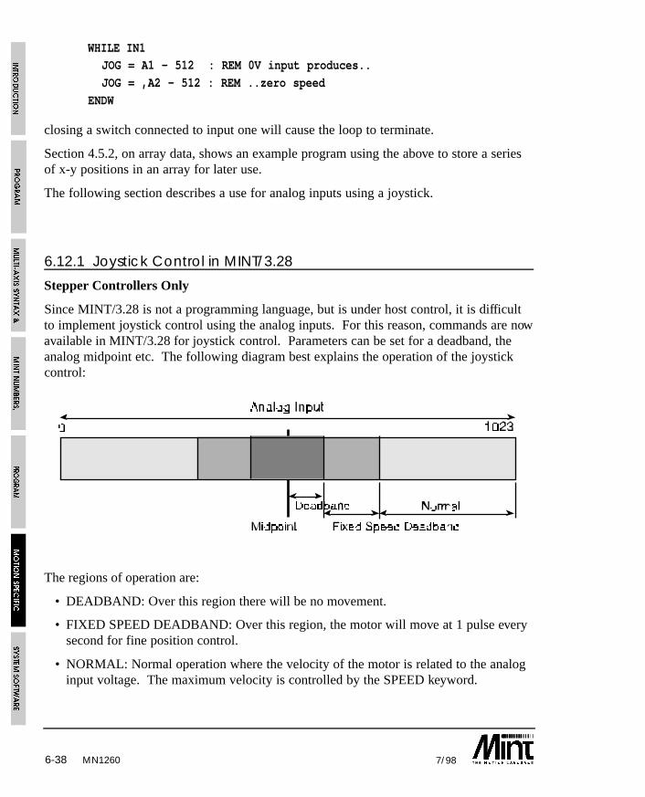
6-38 7/98
WHILE IN1JOG = A1 - 512 : REM 0V input produces..
JOG = ,A2 - 512 : REM ..zero speed
ENDW
closing a switch connected to input one will cause the loop to terminate.
Section 4.5.2, on array data, shows an example program using the above to store a seriesof x-y positions in an array for later use.
The following section describes a use for analog inputs using a joystick.
6.12.1 Joystick Control in MINT/3.28
Stepper Controllers Only
Since MINT/3.28 is not a programming language, but is under host control, it is difficultto implement joystick control using the analog inputs. For this reason, commands are nowavailable in MINT/3.28 for joystick control. Parameters can be set for a deadband, theanalog midpoint etc. The following diagram best explains the operation of the joystickcontrol:
The regions of operation are:
• DEADBAND: Over this region there will be no movement.
• FIXED SPEED DEADBAND: Over this region, the motor will move at 1 pulse everysecond for fine position control.
• NORMAL: Normal operation where the velocity of the motor is related to the analoginput voltage. The maximum velocity is controlled by the SPEED keyword.
MN1260
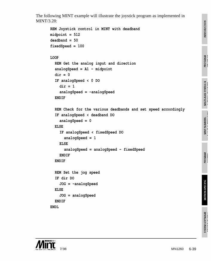
6-397/98
The following MINT example will illustrate the joystick program as implemented inMINT/3.28:
REM Joystick control in MINT with deadband
midpoint = 512deadband = 50
fixedSpeed = 100
LOOP
REM Get the analog input and directionanalogSpeed = A1 - midpoint
dir = 0
IF analogSpeed < 0 DO
dir = 1analogSpeed = -analogSpeed
ENDIF
REM Check for the various deadbands and set speed accordinglyIF analogSpeed < deadband DO
analogSpeed = 0
ELSE
IF analogSpeed < fixedSpeed DOanalogSpeed = 1
ELSE
analogSpeed = analogSpeed - fixedSpeed
ENDIFENDIF
REM Set the jog speed
IF dir DOJOG = -analogSpeed
ELSE
JOG = analogSpeed
ENDIF
ENDL
MN1260
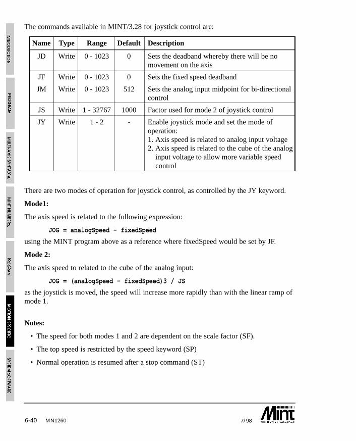
6-40 7/98MN1260
The commands available in MINT/3.28 for joystick control are:
Name Type Range Default Description
JD Write 0 - 1023 0 Sets the deadband whereby there will be nomovement on the axis
JF Write 0 - 1023 0 Sets the fixed speed deadband
JM Write 0 - 1023 512 Sets the analog input midpoint for bi-directionalcontrol
JS Write 1 - 32767 1000 Factor used for mode 2 of joystick control
JY Write 1 - 2 - Enable joystick mode and set the mode ofoperation:1. Axis speed is related to analog input voltage2. Axis speed is related to the cube of the analog
input voltage to allow more variable speedcontrol
There are two modes of operation for joystick control, as controlled by the JY keyword.
Mode1:
The axis speed is related to the following expression:
JOG = analogSpeed - fixedSpeed
using the MINT program above as a reference where fixedSpeed would be set by JF.
Mode 2:
The axis speed to related to the cube of the analog input:
JOG = (analogSpeed - fixedSpeed)3 / JS
as the joystick is moved, the speed will increase more rapidly than with the linear ramp ofmode 1.
Notes:
• The speed for both modes 1 and 2 are dependent on the scale factor (SF).
• The top speed is restricted by the speed keyword (SP)
• Normal operation is resumed after a stop command (ST)
6-417/98
Using cTERM for DOS, the following file can be sent to the controller using theMINT/3.28 ‘Load File’ option.
C;0;RE;6
C;0;DL;6W;0;SP;3;5000,5000
W;0;JD;3;50,50
W;0;JF;3;100,100
W;0;JM;3;512,512
W;0;JS;3;3000,3000W;0;JY;3;2,2
The above parameters will set a deadband (JD) of 50 bits from a midpoint of 512. Thefixed speed deadband (JF) will be between 50 and 100 bits from the midpoint. Mode 2joystick operation is used.
6.13 Input/Output ‘On the Fly’MINT can test and respond to inputs during execution of positional moves because it willcontinue to run until it detects that a move instruction will interfere with one that isalready executing. Consider the following code fragment:
MOVEA = 100 : REM move first axis
GO.0MOVEA = ,200 : REM move second axis
GO.1
MOVEA = 200 : REM set-up next move
GO.0 : REM program hangs here
MINT will start the positional move on axis 0, then start the positional move on axis 1. Itwill then set-up the next positional move on axis 0 as the move pending, but when itcomes to execute GO[0], the program will stop execution until the move on axis 0 iscomplete. Similarly, if a statement GO[0,1] was encountered and a move was in progresson either axis 0 or axis 1, the program would stop execution until that move was complete.
Because MINT does not stop executing instructions until there is a move pending it iseasy to write applications that perform AND operations while a move is in progress.
An example is glue laying around car windows. In this application, the glue cannot beturned on until the axis has reached a critical velocity (VEL), otherwise the line of gluewill not be consistently thick. Therefore we must wait until the axis has acceleratedbefore turning on the glue gun:
MN1260
6-42 7/98
MOVEA = 200 : GO : REM start move PAUSE VEL > 20 : REM wait until VEL > 20
OUT1 = 1 : REM turn on glue
PAUSE VEL < 20 : REM decelerating to end
OUT1 = 0 : REM turn off glue
There are instances when you may wish to halt the program until the current move iscomplete. For instance:
OUT2 = 0
MOVER = 10 : GO : REM relative movePAUSE IDLE : REM wait for end move
OUT2 = 1 : REM flag end move
In this code fragment the requirement is that output two is not set until the move iscomplete. The IDLE keyword will return zero during a positional move and one whenthe axis is idle at the end of the move. Therefore PAUSEing on IDLE will hang theprogram as required.
For a 2 axis move, the code segment will be:
OUT2 = 0MOVER = 10,20 : GO : REM relative move
PAUSE IDLE[0,1] : REM wait for end move
OUT2 = 1 : REM flag end move
Using interrupts, it is possible to interrupt program execution to perform anotheroperation. See section 5.3.2.
6.14 The STOP InputThe STOP input is used to halt motion on all axes. When stop is asserted, motion willramp down to a stop at a deceleration rate set by the ACCEL keyword or crash stop in thecase of FOLLOW and cam profiling. If the input is negated (closed circuit) motion willcommence again and the program will continue to run as normal. An S is displayed onthe status display to indicate that motion has been interrupted.
Typically, the STOP input should be wired to the safety guard on the installation, this willensure that motion is prevented when the guard is lifted. This is a safety requirement.Where the application permits, it is recommended that an external circuit breaker isinstalled to physically cut power to the motor for maximum operator safety.
MN1260
6-437/98
If the STOP subroutine is defined, this will be called if the stop input is asserted. TheSTOP subroutine can be used to pause program execution by reading the state of the stopinput using the STOPSW keyword.
Example:
#STOP
PAUSE !STOPSW : REM Wait for stop input to go lowRETURN : REM Resume execution
The stop input can be configured to initiate a CANCEL on the move in progress. This isconfigured using the STOPMODE keyword.
See the Hardware Guide for more details on the stop input.
6.15 End of Travel Limit InputsThe keyword LIMIT has been provided so that software can directly read the value of theLIMIT switch inputs on axes 0, 1 and 2. The keyword accepts axis parameters in thenormal manner.
Example:
a = LIMIT.1
returns 1 to variable a if the limit input on axis 1 is asserted, 0 if the input is negated.
Example 2:
a = LIMIT[0,1,2]
returns 1 to variable a if the limit inputs on axes 0, 1 and 2 are asserted, 0 if any input isnegated.
When the limit switches are closed, the motion control algorithms will not allow themotors to be driven. Therefore the limit keyword has limited use except in the errorhandling routine ONERROR. The limits can be disables using the DISLIMIT keyword,allowing powered movement to be undertaken while beyond limits. ENLIMIT or RESETwill re-enable the limit switches, RESET will also set the position to zero.
MN1260

6-44 7/98
Example:
#ONERROR
IF ERROR.1 = _limit DO : REM Limit on axis 1?DISLIMIT.1
SERVOFF.1
PAUSE !LIMIT.1
SERVOC.1
ENLIMIT.1ENDIF
RETURN
this example will, on detecting a limit error, disable the limits, and allow manualmovement off the limits. Power is restored and the limits are enabled.
In many applications it is necessary to have separate limit and home switches. Since thecontroller has only one limit input per axis it is best to arrange the active areas of theswitches as shown below:
Hitting a limit switch causes an error which is handled in software by the ONERRORsubroutine. By reading both the state of the limit and home inputs, the left or right limitswitch can be determined as shown in the table:
HOME LIMIT Action
on on Left limit hit
off on Right limit hit
If the home position is midway between the two limits, the active area of the home shouldbe made to extend to either the right or the left to the limit active area.
In an application where not all 3 axes are used, the redundant axes must have theirrespective limit switches grounded (connect to power if PNP inputs are used) for normaloperation. Alternatively the MINT keyword DISLIMIT can be used to disable thedetection of limit switches.
MN1260
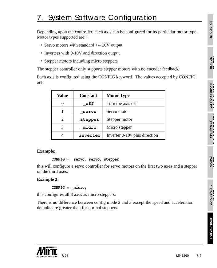
7-17/98 MN1260
7. System Software Configuration
Depending upon the controller, each axis can be configured for its particular motor type.Motor types supported are::
• Servo motors with standard +/- 10V output
• Inverters with 0-10V and direction output
• Stepper motors including micro steppers
The stepper controller only supports stepper motors with no encoder feedback:
Each axis is configured using the CONFIG keyword. The values accepted by CONFIGare:
Value Constant Motor Type
0 _off Turn the axis off
1 _servo Servo motor
2 _stepper Stepper motor
3 _micro Micro stepper
4 _inverter Inverter 0-10v plus direction
Example:
CONFIG = _servo,_servo,_stepper
this will configure a servo controller for servo motors on the first two axes and a stepperon the third axes.
Example 2:
CONFIG = _micro;
this configures all 3 axes as micro steppers.
There is no difference between config mode 2 and 3 except the speed and accelerationdefaults are greater than for normal steppers.
7-2 7/98
7.1 Servo LoopServo Axes Only
At the lowest level of control software, instantaneous axis position demands produced bythe controller software must be translated into motor demands. This is easy with a steppermotor since the control program can simply output a series of steps. As long as thevelocity profile and loading is within the motor’s capability it will follow without missingsteps.
With a servo motor, the inclusion of feedback is necessary, which complicates matterssomewhat. The motor is controlled to minimize the error (the following error) betweendemand and actual position (measured with an incremental encoder). Five hundred timesa second, the controller compares desired and actual positions and calculates the correctdemand for the motor. The torque is calculated by a PIVF (Proportional Integral VelocityFeedback and Velocity Feedforward) algorithm.
Control could be achieved by applying a torque proportional to the error alone, but this isa rather simplistic approach. Imagine that there is a small error between demanded andactual position. A proportional controller will simply multiply the error by some constant,the Proportional gain (GAIN), and apply the resultant to the motor via an amplifier. If thegain is too high this may cause overshoot, which will result in the motor vibrating backand forth around the desired position. As the gain is increased, the controller will presentmore resistance to positional error, but oscillations will increase in magnitude until thesystem becomes completely unstable.
To reduce the onset of instability a damping term is incorporated in the servo loopalgorithm, called Velocity feedback gain (KVEL). This is analogous to putting the motoroutput shaft in syrup. Velocity feedback acts to resist rapid movement of the motor andhence allows the proportional gain to be set higher before vibration sets in.
When the motor is stationary at a set point there may be a small positional error. This ismultiplied by the proportional term to produce an applied torque, but for very small errorsthe torque may not be large enough to overcome static friction. Therefore integral actionis also incorporated in the loop calculations, this involves summing the error over time sothat the torque may be gradually increased until the positional error falls to zero. Thespeed at which integral action works is controlled by the Integral gain (KINT). Integralgain is useful to eliminate steady state positional errors, but will result in reduced dynamicresponse for the system.
The final term in the control loop is Velocity feedforward (KVELFF). This is useful forincreasing the response for velocity servos.
Two types of servo amplifiers may be used with the controller:
• Current or torque amplifiers use the demand signal to control the current flowing inthe motor armature and hence the torque of the motor.
• Velocity controlled amplifiers use the demand signal as a servo speed reference.
MN1260
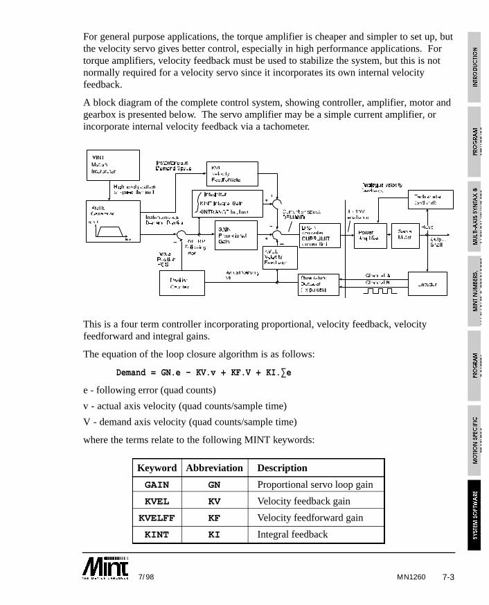
7-37/98
For general purpose applications, the torque amplifier is cheaper and simpler to set up, butthe velocity servo gives better control, especially in high performance applications. Fortorque amplifiers, velocity feedback must be used to stabilize the system, but this is notnormally required for a velocity servo since it incorporates its own internal velocityfeedback.
A block diagram of the complete control system, showing controller, amplifier, motor andgearbox is presented below. The servo amplifier may be a simple current amplifier, orincorporate internal velocity feedback via a tachometer.
This is a four term controller incorporating proportional, velocity feedback, velocityfeedforward and integral gains.
The equation of the loop closure algorithm is as follows:
Demand = GN.e - KV.v + KF.V + KI.∑e
e - following error (quad counts)
v - actual axis velocity (quad counts/sample time)
V - demand axis velocity (quad counts/sample time)
where the terms relate to the following MINT keywords:
Keyword Abbreviation Description
GAIN GN Proportional servo loop gain
KVEL KV Velocity feedback gain
KVELFF KF Velocity feedforward gain
KINT KI Integral feedback
MN1260
7-4 7/98
Tuning the drive involves changing the four servo loop gains, GN, KI, KV and KF toprovide the best performance for your particular motor/encoder combination and loadinertia. In view of the diversity of application, these values all default to zero and shouldbe set up in the system configuration file. You are advised to read the Getting StartedGuide for details on setting these parameters.
Two other keywords, KINTRANGE and CURRLIMIT, are used to control the DACoutput. KINTRANGE, the integration limit, determines the maximum value of the effectof integral action, KI.Se. KINTRANGE is specified as a percentage (%) of the full scaledemand output in the range of ±10V. Therefore if KINTRANGE = 25, the maximumeffect of integral action is ±2.5V.
CURRLIMIT, the current limit, so called for its use with current amplifiers, determinesthe maximum value of the demand output as a percentage of the full scale demand.Therefore if CURRLIMIT = 50, the maximum demand output will be ±5V.
The encoder gain (measured in pulses/rev) is one factor that is hardware dependent but hasa direct effect on the overall loop gain. The other four parameters are software controlledin the range of 0.0-255.0, the resolution of the decimal part is one part in 256 as withnormal MINT variables.
MN1260
7-57/98 MN1260
7.2 Inverter ControlMany inverters have a uni-directional input instead of a bi-directional input. MINTsupports inverters with a uni-directional input by giving a 0-10V reference voltage and adirection output. The actual direction output pin will depend upon the system used whichcan be found from the following lookup table:
System Axis Output pin Output Type
EuroSystem 0 Stepper direction 0 NPN open collector
(including STE) 1 Stepper direction 1 NPN open collector
2 Stepper direction 2 NPN open collector
SmartSystem/1 0 direction axis 0 NPN open collector
SmartSystem/2 0 direction axis 0 NPN open collector
1 direction axis 1 NPN open collector
0 Output bit 7 PNP open collector
EuroServo/3 1 Output bit 6 PNP open collector
2 Output bit 5 PNP open collector
0 Output bit 7 PNP open collector
SmartSystem/3 1 Output bit 6 PNP open collector
2 Output bit 5 PNP open collector
0 Output bit 7 PNP open collector
SmartMove 1 Output bit 6 PNP open collector
2 Output bit 5 PNP open collector
To enable inverter control, write 4 (_inverter) to the CONFIG keyword. For example:
CONFIG = _inverter
Note that for EuroServo/3 and SmartSystem/3, one of the user digital outputs will becomea direction output and cannot be used as a general purpose output.
Since it is not possible to swap the motor demand cables over, as with a bi-directionalsystem, the active output state of the inverter direction can be changed by writing to theDIR keyword.
DIR = 0
the output will be low for a requested negative motor direction (e.g. TQ = -10)
DIR = 1
the output will be high for a requested negative motor direction (e.g. TQ = -10)
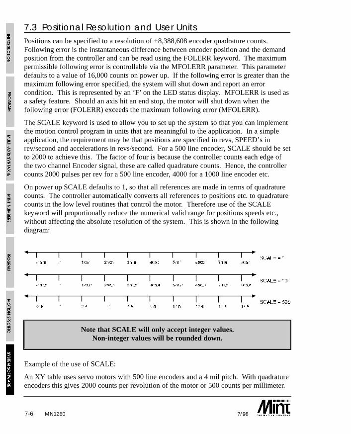
7-6 7/98
7.3 Positional Resolution and User UnitsPositions can be specified to a resolution of ±8,388,608 encoder quadrature counts.Following error is the instantaneous difference between encoder position and the demandposition from the controller and can be read using the FOLERR keyword. The maximumpermissible following error is controllable via the MFOLERR parameter. This parameterdefaults to a value of 16,000 counts on power up. If the following error is greater than themaximum following error specified, the system will shut down and report an errorcondition. This is represented by an ‘F’ on the LED status display. MFOLERR is used asa safety feature. Should an axis hit an end stop, the motor will shut down when thefollowing error (FOLERR) exceeds the maximum following error (MFOLERR).
The SCALE keyword is used to allow you to set up the system so that you can implementthe motion control program in units that are meaningful to the application. In a simpleapplication, the requirement may be that positions are specified in revs, SPEED’s inrev/second and accelerations in revs/second. For a 500 line encoder, SCALE should be setto 2000 to achieve this. The factor of four is because the controller counts each edge ofthe two channel Encoder signal, these are called quadrature counts. Hence, the controllercounts 2000 pulses per rev for a 500 line encoder, 4000 for a 1000 line encoder etc.
On power up SCALE defaults to 1, so that all references are made in terms of quadraturecounts. The controller automatically converts all references to positions etc. to quadraturecounts in the low level routines that control the motor. Therefore use of the SCALEkeyword will proportionally reduce the numerical valid range for positions speeds etc.,without affecting the absolute resolution of the system. This is shown in the followingdiagram:
Note that SCALE will only accept integer values.Non-integer values will be rounded down.
Example of the use of SCALE:
An XY table uses servo motors with 500 line encoders and a 4 mil pitch. With quadratureencoders this gives 2000 counts per revolution of the motor or 500 counts per millimeter.
MN1260
7-77/98
To scale the positions and speeds to millimeters, the following could be used:
SCALE = 500,500 : REM Scale to mm
SPEED = 30,30 : REM Speed = 30 mm/secACCEL = 500,500 : REM Accel = 500 mm/sec^2
MFOLERR = 10,10 : REM Max following error of 10mm
MOVEA = 100,200 : GO : REM Move to position 100,200mm
MOVER = -10,-10 : GO : REM Move relative -10,-10mm
7.4 The Configuration FileThe configuration file is used to store all the defaults appropriate to the particular system.Whenever the program is RUN, the configuration file is first executed. A list ofparameters that you may wish to set up follows:
• Motor type, i.e. stepper or servo.
• Servo loop gains - to tune the system response. See the Getting Started Guide
• Scale factor - to set the units of measure of the application.
• Maximum following error (MFOLERR) - to set a safe maximum difference betweenactual and desired positions.
• Default speeds (SPEED) and accelerations (ACCEL) for the system - to determine theshape of the trapezoidal velocity profile (RAMP).
These parameters are generally set up only once for an application, but can at any time bealtered in the Program File.
MN1260

7-8 7/98
A typical Configuration file for a three axis system is:
< \MANUAL\3AXIS.CFG
AUTO : REM automatic execution on power up
REM Config file for XYZ motor
RESET[0,1,2] : REM to ensure previous setting cleared
AXES[0,1,2]: : REM 3 axis servo system
CONFIG = _servo;
REM system gains
KVEL = 40;GAIN = 10.5;
KINT = 0; : REM in program for 0 posn error
KR = 25;
KVELFF = 0;CURRLIMIT = 100; : REM 100%
REM position/SPEED parameters
SCALE = 2000; : REM units revs (500 line enc)
SPEED = 60; : REM max SPEED 60 revs/sec
ACCEL = 150; : REM max accel 150 revs/sec^2MFOLERR = 1; : REM 1 rev
IDLE = .25;
HMSPEED = 20;
BACKOFF = 10;
In the above example, the default axis list is 0,1,2 so the semicolon is used to apply all theparameters to all three axes.
7.5 Data CaptureMany of the controllers provide a DAC output for system tuning using the AUX keyword.Alternatively, the data capture facility in cTERM for Windows can be used for systemtuning.
There are a number of common problems associated with using the DAC output forsystem tuning:
• An oscilloscope must be available for use.
• The signal from which you are trying to tune from can suffer from noise.
• It can be difficult to record results with all but the most expensive oscilloscopes.
MN1260
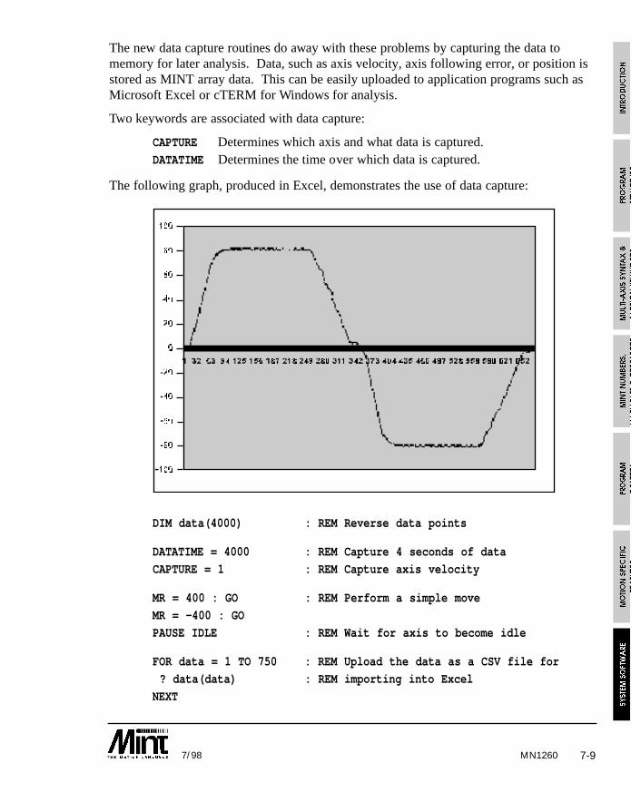
7-97/98
The new data capture routines do away with these problems by capturing the data tomemory for later analysis. Data, such as axis velocity, axis following error, or position isstored as MINT array data. This can be easily uploaded to application programs such asMicrosoft Excel or cTERM for Windows for analysis.
Two keywords are associated with data capture:
CAPTURE Determines which axis and what data is captured. DATATIME Determines the time over which data is captured.
The following graph, produced in Excel, demonstrates the use of data capture:
DIM data(4000) : REM Reverse data points
DATATIME = 4000 : REM Capture 4 seconds of data
CAPTURE = 1 : REM Capture axis velocity
MR = 400 : GO : REM Perform a simple move
MR = -400 : GO
PAUSE IDLE : REM Wait for axis to become idle
FOR data = 1 TO 750 : REM Upload the data as a CSV file for
? data(data) : REM importing into Excel
NEXT
MN1260
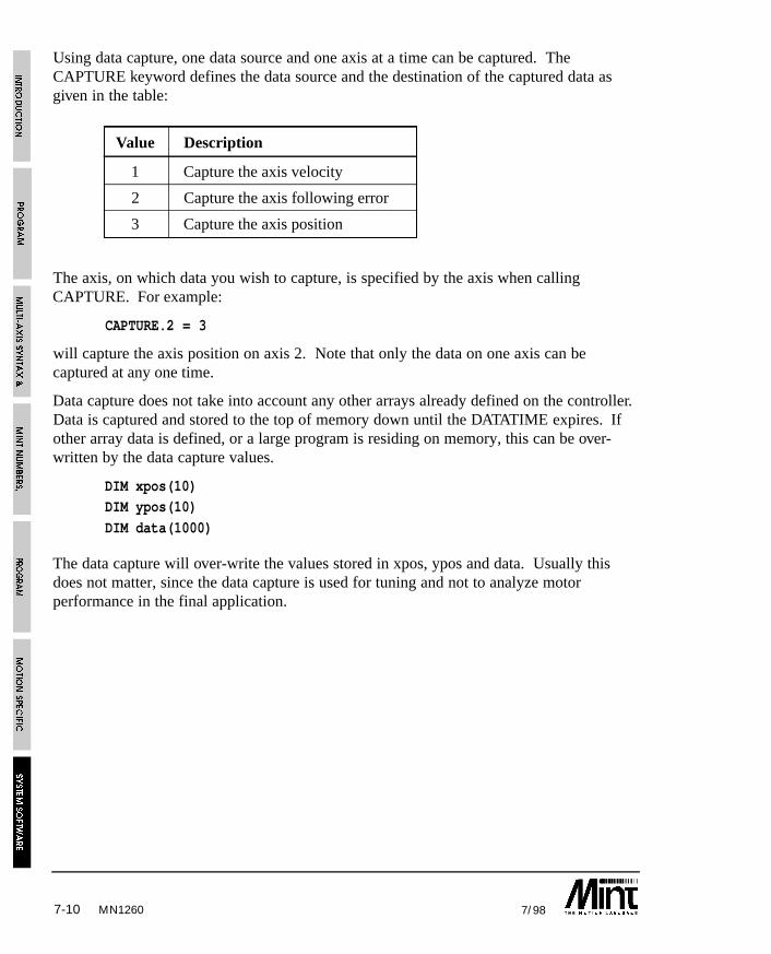
7-10 7/98MN1260
Using data capture, one data source and one axis at a time can be captured. TheCAPTURE keyword defines the data source and the destination of the captured data asgiven in the table:
Value Description
1 Capture the axis velocity
2 Capture the axis following error
3 Capture the axis position
The axis, on which data you wish to capture, is specified by the axis when callingCAPTURE. For example:
CAPTURE.2 = 3
will capture the axis position on axis 2. Note that only the data on one axis can becaptured at any one time.
Data capture does not take into account any other arrays already defined on the controller.Data is captured and stored to the top of memory down until the DATATIME expires. Ifother array data is defined, or a large program is residing on memory, this can be over-written by the data capture values.
DIM xpos(10)DIM ypos(10)
DIM data(1000)
The data capture will over-write the values stored in xpos, ypos and data. Usually thisdoes not matter, since the data capture is used for tuning and not to analyze motorperformance in the final application.
MN1260 8-17/98
8. Program and Motion ErrorsErrors can be broken down into the following groups:
1. System errors
System errors include:
• Motion in Progress
• Out of Range
• Invalid Mode
• Servo Off
2. Motion errors
Motion errors include:
• Limit error
• Following error exceeded.
• External error
3. Programming errors
Run-time language errors such as Syntax Error.
MINT is able to handle a number of error conditions through the use of the keywordsERROR, ERRAXIS and ERR. When an error occurs, the error handler is called. This isdefined by placing a subroutine, #ONERROR, within the program. Only System Errorsand Motion Errors can be trapped within an ONERROR routine.
The ERR keyword is used to determine the nature of the error and ERRAXIS the axis onwhich the error occurred. ERR codes are as follows:
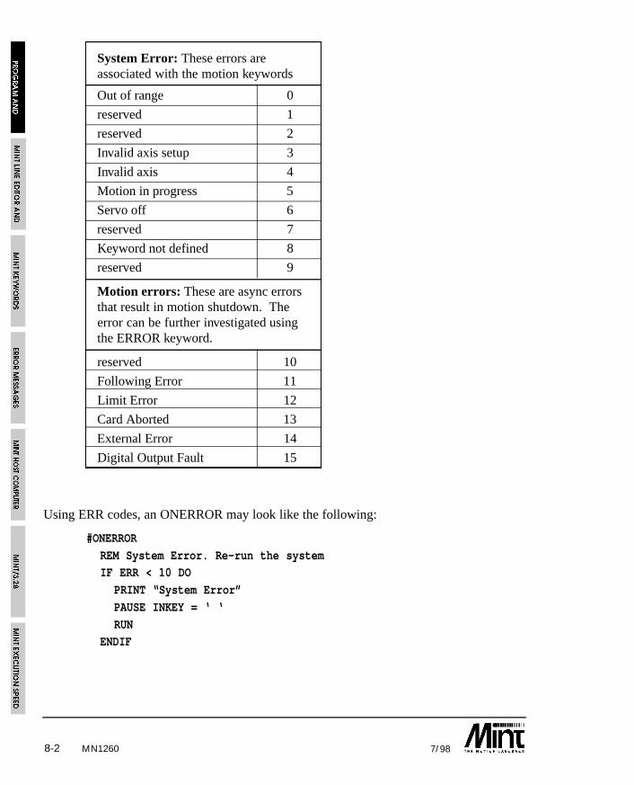
MN12608-2 7/98
System Error: These errors areassociated with the motion keywords
Out of range 0
reserved 1
reserved 2
Invalid axis setup 3
Invalid axis 4
Motion in progress 5
Servo off 6
reserved 7
Keyword not defined 8
reserved 9
Motion errors: These are async errorsthat result in motion shutdown. Theerror can be further investigated usingthe ERROR keyword.
reserved 10
Following Error 11
Limit Error 12
Card Aborted 13
External Error 14
Digital Output Fault 15
Using ERR codes, an ONERROR may look like the following:
#ONERROR
REM System Error. Re-run the systemIF ERR < 10 DO
PRINT “System Error”
PAUSE INKEY = ‘ ‘
RUNENDIF
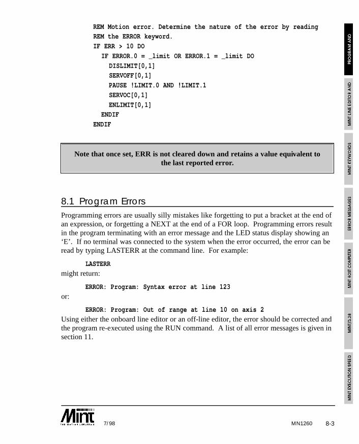
MN1260 8-37/98
REM Motion error. Determine the nature of the error by readingREM the ERROR keyword.
IF ERR > 10 DO
IF ERROR.0 = _limit OR ERROR.1 = _limit DO
DISLIMIT[0,1]SERVOFF[0,1]
PAUSE !LIMIT.0 AND !LIMIT.1
SERVOC[0,1]
ENLIMIT[0,1]ENDIF
ENDIF
Note that once set, ERR is not cleared down and retains a value equivalent tothe last reported error.
8.1 Program ErrorsProgramming errors are usually silly mistakes like forgetting to put a bracket at the end ofan expression, or forgetting a NEXT at the end of a FOR loop. Programming errors resultin the program terminating with an error message and the LED status display showing an‘E’. If no terminal was connected to the system when the error occurred, the error can beread by typing LASTERR at the command line. For example:
LASTERR
might return:
ERROR: Program: Syntax error at line 123
or:
ERROR: Program: Out of range at line 10 on axis 2
Using either the onboard line editor or an off-line editor, the error should be corrected andthe program re-executed using the RUN command. A list of all error messages is given insection 11.
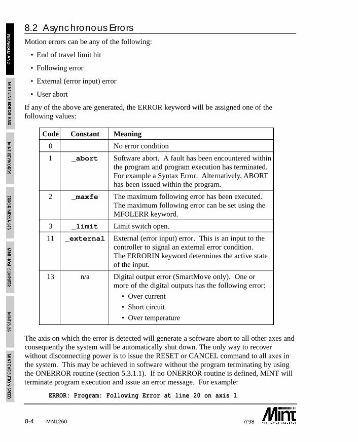
MN12608-4 7/98
8.2 Asynchronous ErrorsMotion errors can be any of the following:
• End of travel limit hit
• Following error
• External (error input) error
• User abort
If any of the above are generated, the ERROR keyword will be assigned one of thefollowing values:
Code Constant Meaning
0 No error condition
1 _abort Software abort. A fault has been encountered withinthe program and program execution has terminated.For example a Syntax Error. Alternatively, ABORThas been issued within the program.
2 _maxfe The maximum following error has been executed.The maximum following error can be set using theMFOLERR keyword.
3 _limit Limit switch open.
11 _external External (error input) error. This is an input to thecontroller to signal an external error condition.The ERRORIN keyword determines the active stateof the input.
13 n/a Digital output error (SmartMove only). One ormore of the digital outputs has the following error:
• Over current
• Short circuit
• Over temperature
The axis on which the error is detected will generate a software abort to all other axes andconsequently the system will be automatically shut down. The only way to recoverwithout disconnecting power is to issue the RESET or CANCEL command to all axes inthe system. This may be achieved in software without the program terminating by usingthe ONERROR routine (section 5.3.1.1). If no ONERROR routine is defined, MINT willterminate program execution and issue an error message. For example:
ERROR: Program: Following Error at line 20 on axis 1
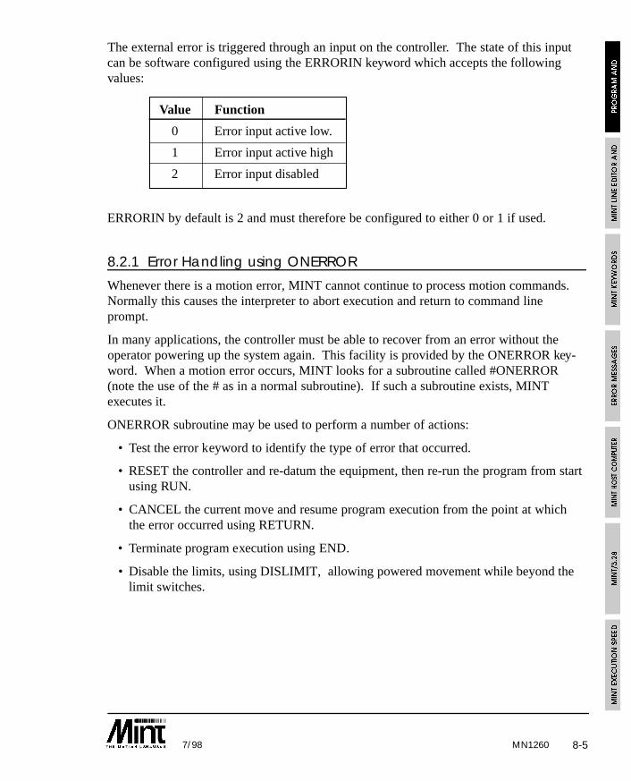
MN1260 8-57/98
The external error is triggered through an input on the controller. The state of this inputcan be software configured using the ERRORIN keyword which accepts the followingvalues:
Value Function
0 Error input active low.
1 Error input active high
2 Error input disabled
ERRORIN by default is 2 and must therefore be configured to either 0 or 1 if used.
8.2.1 Error Handling using ONERROR
Whenever there is a motion error, MINT cannot continue to process motion commands.Normally this causes the interpreter to abort execution and return to command lineprompt.
In many applications, the controller must be able to recover from an error without theoperator powering up the system again. This facility is provided by the ONERROR key-word. When a motion error occurs, MINT looks for a subroutine called #ONERROR(note the use of the # as in a normal subroutine). If such a subroutine exists, MINTexecutes it.
ONERROR subroutine may be used to perform a number of actions:
• Test the error keyword to identify the type of error that occurred.
• RESET the controller and re-datum the equipment, then re-run the program from startusing RUN.
• CANCEL the current move and resume program execution from the point at whichthe error occurred using RETURN.
• Terminate program execution using END.
• Disable the limits, using DISLIMIT, allowing powered movement while beyond thelimit switches.
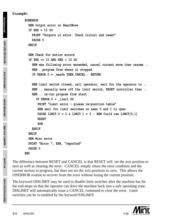
MN12608-6 7/98
Example:
#ONERROR
REM Output error on SmartMoveIF ERR = 15 DO
PRINT “Outputs in error. Check circuit and reset”
PAUSE 0
ENDIF
REM Check for motion errors
IF ERR >= 10 AND ERR < 15 DO
REM max following error exceeded, cancel current move then resume ..
REM ..program from where it stoppedIF ERROR.0 = _maxfe THEN CANCEL : RETURN
REM limit switch closed, call operator, wait for the operator to ..
REM .. manually move off the limit switch, RESET controller then ..REM .. re-run program from start
IF ERROR.0 = _limit DO
PRINT “Limit error - please re-position table”
REM wait for limit switches on axes 0 and 1 to open PAUSE LIMIT.0 = 0 & LIMIT.1 = 0 : REM Could use LIMIT[0,1]
RESET
RUN
ENDIFENDIF
REM Misc error
PRINT “Error “, ERR, “reported”
PAUSE 0END
The difference between RESET and CANCEL is that RESET will set the axis position tozero as well as clearing the error. CANCEL simply clears the error condition and thecurrent motion in progress, but does not set the axis positions to zero. This allows theONERROR routine to recover from the error without losing the current position.
The keyword DISLIMIT may be used to disable limit switches after the machine has hitthe end-stops so that the operator can drive the machine back into a safe operating zone.DISLIMIT will automatically issue a CANCEL command to clear the error. Limitswitches can be re-enabled by the keyword ENLIMIT.
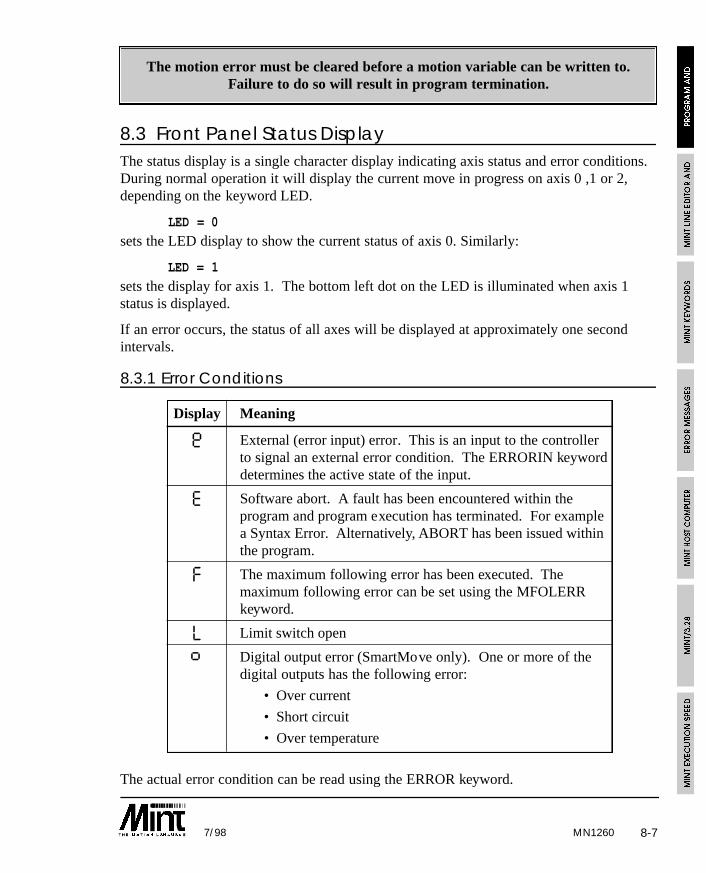
MN1260 8-77/98
The motion error must be cleared before a motion variable can be written to.Failure to do so will result in program termination.
8.3 Front Panel Status DisplayThe status display is a single character display indicating axis status and error conditions.During normal operation it will display the current move in progress on axis 0 ,1 or 2,depending on the keyword LED.
LED = 0
sets the LED display to show the current status of axis 0. Similarly:
LED = 1
sets the display for axis 1. The bottom left dot on the LED is illuminated when axis 1status is displayed.
If an error occurs, the status of all axes will be displayed at approximately one secondintervals.
8.3.1 Error Conditions
Display Meaning
Ø External (error input) error. This is an input to the controllerto signal an external error condition. The ERRORIN keyworddetermines the active state of the input.
E Software abort. A fault has been encountered within theprogram and program execution has terminated. For examplea Syntax Error. Alternatively, ABORT has been issued withinthe program.
F The maximum following error has been executed. Themaximum following error can be set using the MFOLERRkeyword.
L Limit switch open
ß Digital output error (SmartMove only). One or more of thedigital outputs has the following error:
• Over current
• Short circuit
• Over temperature
The actual error condition can be read using the ERROR keyword.
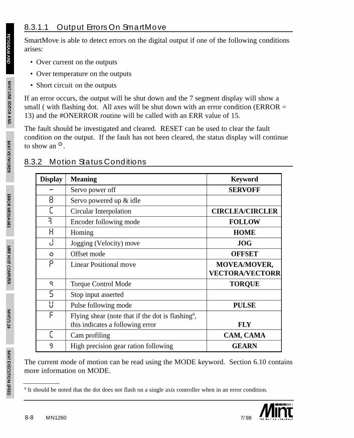
MN12608-8 7/98
8 It should be noted that the dot does not flash on a single axis controller when in an error condition.
8.3.1.1 Output Errors On SmartMove
SmartMove is able to detect errors on the digital output if one of the following conditionsarises:
• Over current on the outputs
• Over temperature on the outputs
• Short circuit on the outputs
If an error occurs, the output will be shut down and the 7 segment display will show asmall ( with flashing dot. All axes will be shut down with an error condition (ERROR =13) and the #ONERROR routine will be called with an ERR value of 15.
The fault should be investigated and cleared. RESET can be used to clear the faultcondition on the output. If the fault has not been cleared, the status display will continueto show an ß.
8.3.2 Motion Status Conditions
Display Meaning Keyword
– Servo power off SERVOFF
8 Servo powered up & idle
C Circular Interpolation CIRCLEA/CIRCLER
Æ Encoder following mode FOLLOW
H Homing HOME
J Jogging (Velocity) move JOG
o Offset mode OFFSET
P Linear Positional move MOVEA/MOVER,VECTORA/VECTORR
q Torque Control Mode TORQUE
S Stop input asserted
U Pulse following mode PULSE
F Flying shear (note that if the dot is flashing8,this indicates a following error FLY
C Cam profiling CAM, CAMA
g High precision gear ration following GEARN
The current mode of motion can be read using the MODE keyword. Section 6.10 containsmore information on MODE.
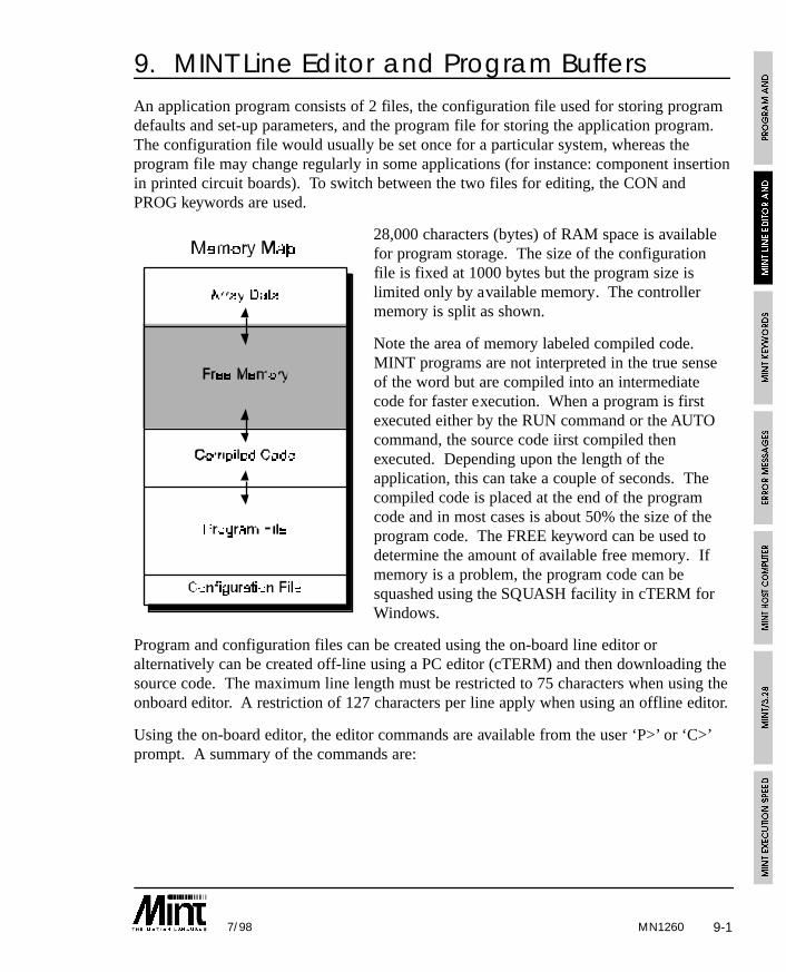
MN1260 9-17/98
9. MINT Line Editor and Program BuffersAn application program consists of 2 files, the configuration file used for storing programdefaults and set-up parameters, and the program file for storing the application program.The configuration file would usually be set once for a particular system, whereas theprogram file may change regularly in some applications (for instance: component insertionin printed circuit boards). To switch between the two files for editing, the CON andPROG keywords are used.
28,000 characters (bytes) of RAM space is availablefor program storage. The size of the configurationfile is fixed at 1000 bytes but the program size islimited only by available memory. The controllermemory is split as shown.
Note the area of memory labeled compiled code.MINT programs are not interpreted in the true senseof the word but are compiled into an intermediatecode for faster execution. When a program is firstexecuted either by the RUN command or the AUTOcommand, the source code iirst compiled thenexecuted. Depending upon the length of theapplication, this can take a couple of seconds. Thecompiled code is placed at the end of the programcode and in most cases is about 50% the size of theprogram code. The FREE keyword can be used todetermine the amount of available free memory. Ifmemory is a problem, the program code can besquashed using the SQUASH facility in cTERM forWindows.
Program and configuration files can be created using the on-board line editor oralternatively can be created off-line using a PC editor (cTERM) and then downloading thesource code. The maximum line length must be restricted to 75 characters when using theonboard editor. A restriction of 127 characters per line apply when using an offline editor.
Using the on-board editor, the editor commands are available from the user ‘P>’ or ‘C>’prompt. A summary of the commands are:
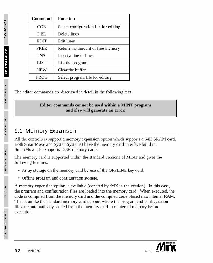
MN12609-2 7/98
Command Function
CON Select configuration file for editing
DEL Delete lines
EDIT Edit lines
FREE Return the amount of free memory
INS Insert a line or lines
LIST List the program
NEW Clear the buffer
PROG Select program file for editing
The editor commands are discussed in detail in the following text.
Editor commands cannot be used within a MINT programand if so will generate an error.
9.1 Memory ExpansionAll the controllers support a memory expansion option which supports a 64K SRAM card.Both SmartMove and SystemSystem/3 have the memory card interface build in.SmartMove also supports 128K memory cards.
The memory card is supported within the standard versions of MINT and gives thefollowing features:
• Array storage on the memory card by use of the OFFLINE keyword.
• Offline program and configuration storage.
A memory expansion option is available (denoted by /MX in the version). In this case,the program and configuration files are loaded into the memory card. When executed, thecode is compiled from the memory card and the compiled code placed into internal RAM.This is unlike the standard memory card support where the program and configurationfiles are automatically loaded from the memory card into internal memory beforeexecution.
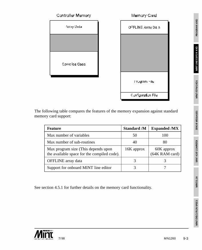
MN1260 9-37/98
The following table compares the features of the memory expansion against standardmemory card support:
Feature Standard /M Expanded /MX
Max number of variables 50 100
Max number of sub-routines 40 80
Max program size (This depends upon 16K approx 60K approxthe available space for the compiled code). (64K RAM card)
OFFLINE array data 3 3
Support for onboard MINT line editor 3 7
See section 4.5.1 for further details on the memory card functionality.
MN12609-4 7/98
9.2 Password ProtectionThe program and configuration file can be password protected by use of the PROTECTkeyword. The keyword is placed at the top of the program file following by the password.For example:
PROTECT abc
REM Program #1
GOSUB init
GOSUB main#init
...
If any of the editor commands are used such as LIST, LOAD or SAVE, MINT will displaythe following:
Password?
requesting you to enter the password. The password when entered is displayed as *’s. Ifthe password is rejected, nothing happens, if the password is accepted the editor commandwill be carried out.
See the PROTECT keyword in section 10 for further details.
9.3 Editor Commands
CON
Purpose:
Select the configuration file for editing.
Format:
CONSelects the configuration file for editing. The command line prompt will change to ‘C>’and the number of bytes used by the configuration file will be displayed:
Card #0
Configuration: 249 Bytes Free (750 Used) 21 lines
Variables: #16 Arrays: #0
See also:
FREE, NEW, PROG
MN1260 9-57/98
DEL
Format:
DEL <line number> {, <line number>}
Deletes a single line, or a block of lines between two line numbers, from the source code.Once a line is deleted, it cannot be recovered.
Example:
DEL 10,20delete lines 10 to 20 inclusive.
See also:
EDIT, INS
EDIT
Format:
EDIT {<line number>}
If no line number is specified, the EDIT keyword appends lines of text to the end of theprogram. The prompt will change to the line number and ‘>’ character. To terminateediting, press Return on a blank line.
If a line number is specified, the line to be edited will be displayed. For instance, to editline 4 of a program, type:
EDIT 4
The line editor allows you to edit lines using the cursor keys on a PC. With cTERM thecursor keys are used to move the cursor left and right over the line. The text can beoverwritten or blank spaces inserted into the line using the Ins key. The backspace keywill delete characters to the left of the cursor. All characters to the right of the cursor aremoved left one character space. The Home key will move the cursor to the beginning ofthe line and the End key will move the cursor to the end of the line.
The editor keys are duplicated on the control keys:
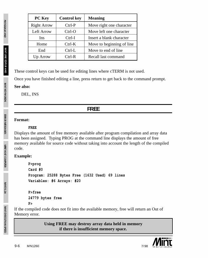
MN12609-6 7/98
PC Key Control key Meaning
Right Arrow Ctrl-P Move right one character
Left Arrow Ctrl-O Move left one character
Ins Ctrl-I Insert a blank character
Home Ctrl-K Move to beginning of line
End Ctrl-L Move to end of line
Up Arrow Ctrl-R Recall last command
These control keys can be used for editing lines where cTERM is not used.
Once you have finished editing a line, press return to get back to the command prompt.
See also:
DEL, INS
FREE
Format:
FREEDisplays the amount of free memory available after program compilation and array datahas been assigned. Typing PROG at the command line displays the amount of freememory available for source code without taking into account the length of the compiledcode.
Example:
P>prog
Card #0
Program: 25288 Bytes Free (1632 Used) 69 linesVariables: #6 Arrays: #20
P>free
24779 bytes freeP>
If the compiled code does not fit into the available memory, free will return an Out ofMemory error.
Using FREE may destroy array data held in memoryif there is insufficient memory space.
MN1260 9-77/98
INS
Format:
INS <line number>
A line is inserted above the line number specified and the line numbers are adjustedaccordingly. For example:
INS 4will insert the new line between line 3 and 4. Further lines will be inserted as long as youcontinue to type. To terminate editing press Return/Enter on an empty line.
See also:
DEL, EDIT
LIST
Format:
LIST {<line number> {,<line number>}}
Lists a single line, or a block of lines between two line numbers. By entering LIST withno parameters, the entire program will be listed to the screen, this can be aborted bypressing Ctrl-E.
Example:
LIST 10,30
will list program lines 10 to 30 inclusive.
NEW
Format:
NEW
Clears the current buffer of all text. Once NEW has been entered, the source code cannotbe retrieved.
See also:
CON, PROG
MN12609-8 7/98
PROG
Format:
PROG
Selects the program file for editing. The command line prompt will change to ‘P>’ andthe number of bytes used by the program file will be displayed:
Card #0Program: 23179 Bytes Free (3821 Used) 263 lines
Variables: #16 Arrays: #0
See also:
CON, FREE, NEW
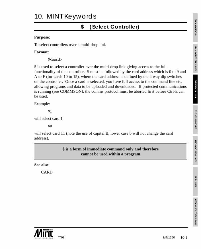
MN1260 10-17/98
10. MINT Keywords
$ (Select Controller)
Purpose:
To select controllers over a multi-drop link
Format:
$<card>
$ is used to select a controller over the multi-drop link giving access to the fullfunctionality of the controller. $ must be followed by the card address which is 0 to 9 andA to F (for cards 10 to 15), where the card address is defined by the 4 way dip switcheson the controller. Once a card is selected, you have full access to the command line etc.allowing programs and data to be uploaded and downloaded. If protected communicationsis running (see COMMSON), the comms protocol must be aborted first before Ctrl-E canbe used.
Example:
$1
will select card 1
$B
will select card 11 (note the use of capital B, lower case b will not change the cardaddress).
$ is a form of immediate command only and thereforecannot be used within a program
See also:
CARD
MN126010-2 7/98
: (Command Separator)
Purpose:
To separate multiple commands on a line.
Format:
:
A colon separates multiple statement on a single line of code.
Examples:
gain = 10 : PRINT gain
IF IN1 THEN OUT1 = 1 : SPEED = 10
# (Subroutine Label)
Purpose:
To define a label for use with GOSUB or GOTO.
Format:
# subroutine_name
A subroutine label is prefixed with a hash ‘#’ where each label can be up to 10 charactersin length. If two labels have the same name, an error is generated.
Example:
A subroutine that performs ten incremental moves:
#move_10
FOR i = 0 to 10
MOVER = 1 : GO
NEXTRETURN
The subroutine is called with:
GOSUB move_10
Note that the hash is not used in the GOSUB statement.
See also:
#FASTPOS, #IN0..#IN7, #ONERROR, #STOP, GOSUB, GOTO, RETURN
10-37/98
#FASTPOS
Purpose:
To define an interrupt routine that is called in response to a fast interrupt.
Format:
#FASTPOS...RETURN
Defines an interrupt routine on the fast interrupt input pin. The interrupt routine is calledon a rising edge (a transition of 0 to 1 as seen by the controller – inactive to active state)of the input. The fast interrupt will also latch the instantaneous axis positions and storethe values to the FASTPOS keyword. The routine can be disabled using the DINTkeyword and re-enabled using EINT.
In addition to latching the axis positions, the interrupt will also latch the encoder values tothe FASTENC keyword.
See the section 5.3.2.1 for more details.
See also:DINT, EINT, FASTENC, FASTPOS, #IN0..#IN7, RETURN
#IN0 .. #IN7 (User Interrupts)
Purpose:
To define an interrupt routine on a digital input.
Format:
#INx
Defines an interrupt routine on a digital input (IN0 to IN7). The interrupt routine is calledon a falling edge (a transition of 1 to 0 as seen by the controller – active to inactive state)of the input. See the section 5.3.3 for more details.
Example:
#IN3STOP.0PAUSE IDLE.0
RETURN
will stop any motion on axis 0 if a falling edge is seen on interrupt 3.
See also:IN0..IN7, RETURN
MN1260
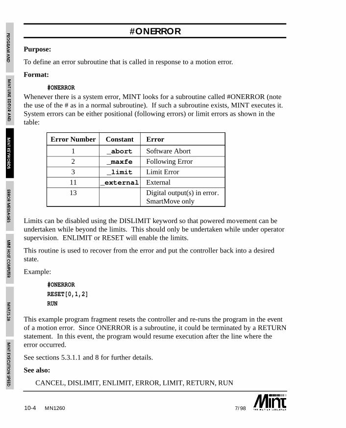
10-4 7/98MN1260
#ONERROR
Purpose:
To define an error subroutine that is called in response to a motion error.
Format:
#ONERROR
Whenever there is a system error, MINT looks for a subroutine called #ONERROR (notethe use of the # as in a normal subroutine). If such a subroutine exists, MINT executes it.System errors can be either positional (following errors) or limit errors as shown in thetable:
Error Number Constant Error
1 _abort Software Abort
2 _maxfe Following Error
3 _limit Limit Error
11 _external External
13 Digital output(s) in error.SmartMove only
Limits can be disabled using the DISLIMIT keyword so that powered movement can beundertaken while beyond the limits. This should only be undertaken while under operatorsupervision. ENLIMIT or RESET will enable the limits.
This routine is used to recover from the error and put the controller back into a desiredstate.
Example:
#ONERROR
RESET[0,1,2]
RUN
This example program fragment resets the controller and re-runs the program in the eventof a motion error. Since ONERROR is a subroutine, it could be terminated by a RETURNstatement. In this event, the program would resume execution after the line where theerror occurred.
See sections 5.3.1.1 and 8 for further details.
See also:
CANCEL, DISLIMIT, ENLIMIT, ERROR, LIMIT, RETURN, RUN
10-57/98
#STOP
Purpose:
To define a STOP subroutine that is called in response to a stop input.
Format:
#STOP
Subroutine called in response to a rising edge (a transition of 0 to 1 as seen by thecontroller – inactive to active state) on the stop input. This can be used to halt programexecution and set some inputs etc. on a stop input.
Example:
#STOP
PAUSE !STOPSW : REM Wait for stop input
RETURN : REM Resume execution
Should the STOP subroutine terminate before the stop input is de-activated, the STOPsubroutine will not be called until another rising edge is seen.
See section 5.3 for more details on MINT interrupt routines.
See also:
RETURN, STOPMODE, STOPSW
ABORT/AB
Purpose:
To abort motion on all axes.
Format:
ABORT
MN1260
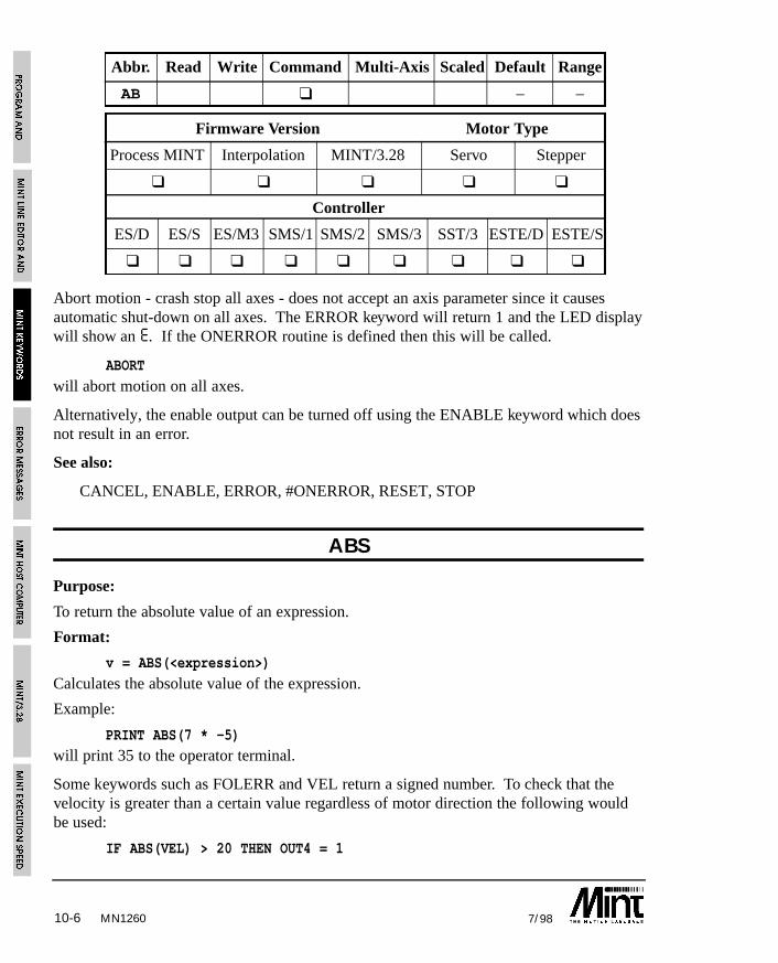
10-6 7/98MN1260
Abbr. Read Write Command Multi-Axis Scaled Default Range
AB ❑ – –
Firmware Version Motor Type
Process MINT Interpolation MINT/3.28 Servo Stepper
❑ ❑ ❑ ❑ ❑
Controller
ES/D ES/S ES/M3 SMS/1 SMS/2 SMS/3 SST/3 ESTE/D ESTE/S
❑ ❑ ❑ ❑ ❑ ❑ ❑ ❑ ❑
Abort motion - crash stop all axes - does not accept an axis parameter since it causesautomatic shut-down on all axes. The ERROR keyword will return 1 and the LED displaywill show an E. If the ONERROR routine is defined then this will be called.
ABORT
will abort motion on all axes.
Alternatively, the enable output can be turned off using the ENABLE keyword which doesnot result in an error.
See also:
CANCEL, ENABLE, ERROR, #ONERROR, RESET, STOP
ABS
Purpose:
To return the absolute value of an expression.
Format:
v = ABS(<expression>)
Calculates the absolute value of the expression.
Example:
PRINT ABS(7 * -5)will print 35 to the operator terminal.
Some keywords such as FOLERR and VEL return a signed number. To check that thevelocity is greater than a certain value regardless of motor direction the following wouldbe used:
IF ABS(VEL) > 20 THEN OUT4 = 1
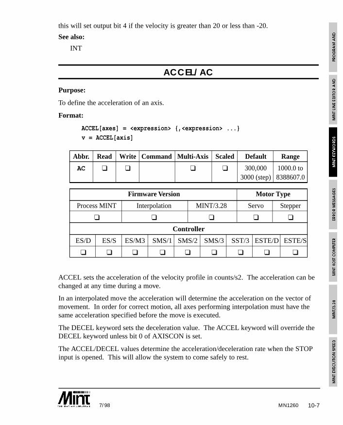
10-77/98 MN1260
this will set output bit 4 if the velocity is greater than 20 or less than -20.
See also:
INT
ACCEL/AC
Purpose:
To define the acceleration of an axis.
Format:
ACCEL[axes] = <expression> {,<expression> ...}
v = ACCEL[axis]
Abbr. Read Write Command Multi-Axis Scaled Default Range
AC ❑ ❑ ❑ ❑ 300,000 1000.0 to3000 (step) 8388607.0
Firmware Version Motor Type
Process MINT Interpolation MINT/3.28 Servo Stepper
❑ ❑ ❑ ❑ ❑
Controller
ES/D ES/S ES/M3 SMS/1 SMS/2 SMS/3 SST/3 ESTE/D ESTE/S
❑ ❑ ❑ ❑ ❑ ❑ ❑ ❑ ❑
ACCEL sets the acceleration of the velocity profile in counts/s2. The acceleration can bechanged at any time during a move.
In an interpolated move the acceleration will determine the acceleration on the vector ofmovement. In order for correct motion, all axes performing interpolation must have thesame acceleration specified before the move is executed.
The DECEL keyword sets the deceleration value. The ACCEL keyword will override theDECEL keyword unless bit 0 of AXISCON is set.
The ACCEL/DECEL values determine the acceleration/deceleration rate when the STOPinput is opened. This will allow the system to come safely to rest.
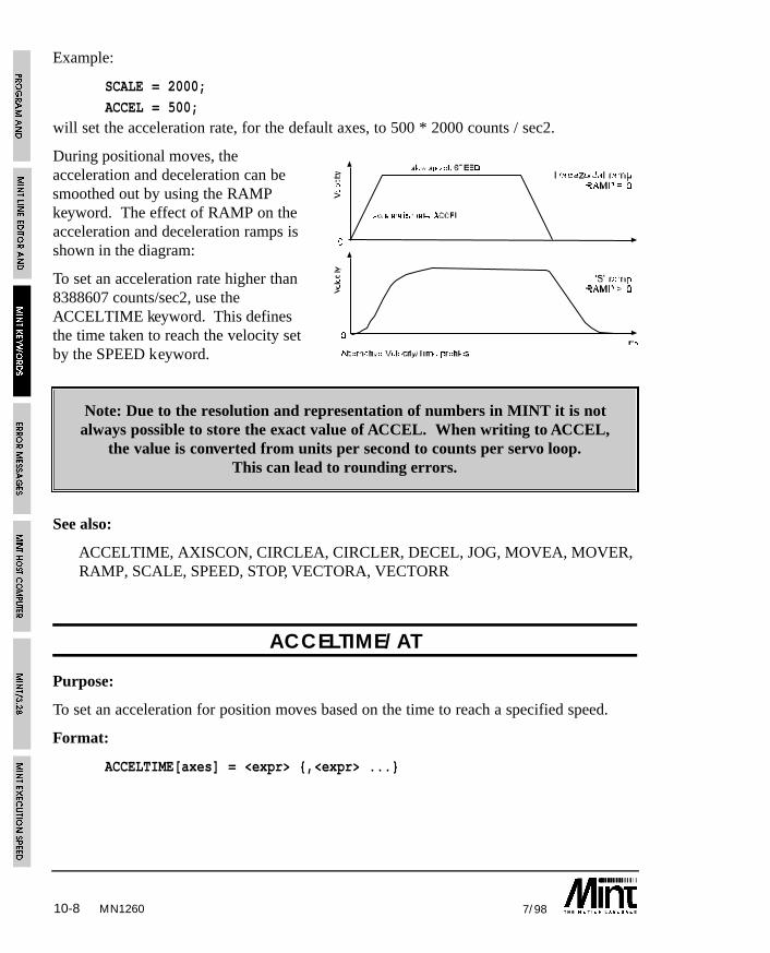
10-8 7/98
Example:
SCALE = 2000;
ACCEL = 500;will set the acceleration rate, for the default axes, to 500 * 2000 counts / sec2.
During positional moves, theacceleration and deceleration can besmoothed out by using the RAMPkeyword. The effect of RAMP on theacceleration and deceleration ramps isshown in the diagram:
To set an acceleration rate higher than8388607 counts/sec2, use theACCELTIME keyword. This definesthe time taken to reach the velocity setby the SPEED keyword.
Note: Due to the resolution and representation of numbers in MINT it is notalways possible to store the exact value of ACCEL. When writing to ACCEL,
the value is converted from units per second to counts per servo loop.This can lead to rounding errors.
See also:
ACCELTIME, AXISCON, CIRCLEA, CIRCLER, DECEL, JOG, MOVEA, MOVER, RAMP, SCALE, SPEED, STOP, VECTORA, VECTORR
ACCELTIME/AT
Purpose:
To set an acceleration for position moves based on the time to reach a specified speed.
Format:
ACCELTIME[axes] = <expr> {,<expr> ...}
MN1260
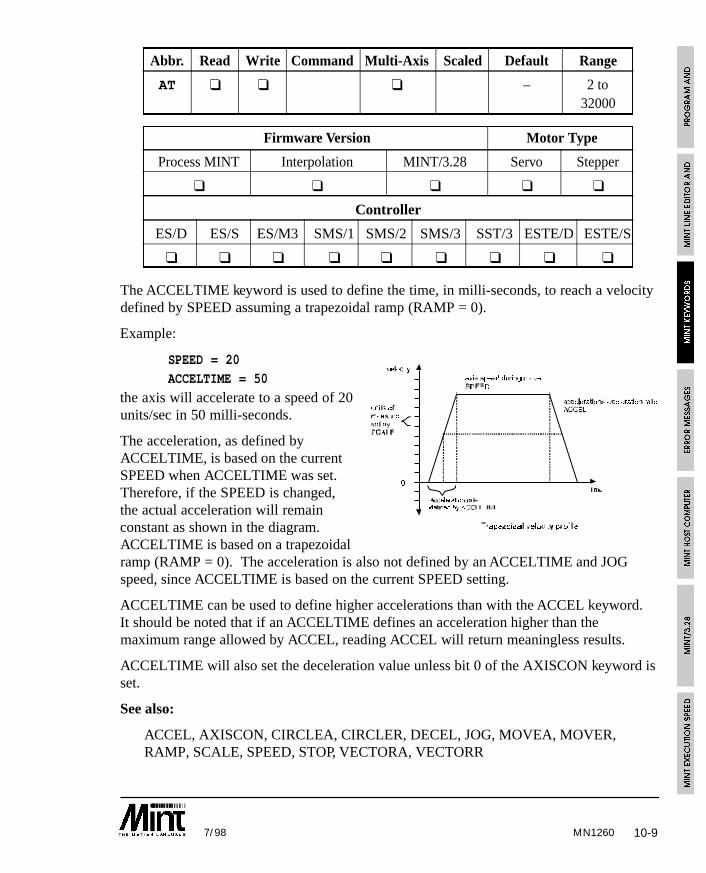
10-97/98 MN1260
Abbr. Read Write Command Multi-Axis Scaled Default Range
AT ❑ ❑ ❑ – 2 to32000
Firmware Version Motor Type
Process MINT Interpolation MINT/3.28 Servo Stepper
❑ ❑ ❑ ❑ ❑
Controller
ES/D ES/S ES/M3 SMS/1 SMS/2 SMS/3 SST/3 ESTE/D ESTE/S
❑ ❑ ❑ ❑ ❑ ❑ ❑ ❑ ❑
The ACCELTIME keyword is used to define the time, in milli-seconds, to reach a velocitydefined by SPEED assuming a trapezoidal ramp (RAMP = 0).
Example:
SPEED = 20ACCELTIME = 50
the axis will accelerate to a speed of 20units/sec in 50 milli-seconds.
The acceleration, as defined byACCELTIME, is based on the currentSPEED when ACCELTIME was set.Therefore, if the SPEED is changed,the actual acceleration will remainconstant as shown in the diagram.ACCELTIME is based on a trapezoidalramp (RAMP = 0). The acceleration is also not defined by an ACCELTIME and JOGspeed, since ACCELTIME is based on the current SPEED setting.
ACCELTIME can be used to define higher accelerations than with the ACCEL keyword.It should be noted that if an ACCELTIME defines an acceleration higher than themaximum range allowed by ACCEL, reading ACCEL will return meaningless results.
ACCELTIME will also set the deceleration value unless bit 0 of the AXISCON keyword isset.
See also:
ACCEL, AXISCON, CIRCLEA, CIRCLER, DECEL, JOG, MOVEA, MOVER,RAMP, SCALE, SPEED, STOP, VECTORA, VECTORR

10-10 7/98MN1260
9Available only on 3 axis servo controller
ANALOGUE1/A1ANALOGUE2/A2
ANALOGUE3/A3*
Purpose:
To read the 10 bit analog inputs.
Format:v = ANALOGUE1V = ANALOGUE2V = ANALOGUE3
Abbr. Read Write Command Multi-Axis Scaled Default Range
A1 ❑ – 0 toA2 1023A39
Firmware Version Motor Type
Process MINT Interpolation MINT/3.28 Servo Stepper
❑ ❑ ❑ ❑ ❑
Controller
ES/D ES/S ES/M3 SMS/1 SMS/2 SMS/3 SST/3 ESTE/D ESTE/S
❑ ❑ ❑ ❑ ❑ ❑ ❑ ❑ ❑
Returns the value of the specified analog input. Each input has a ±10V or 0 to 5V rangewhich is jumper selectable, with 10 bit conversion resolution. See the hardwareinstallation manual for further details.
The analog ports can be used to provide XY control through a joystick (see section6.12.1).
Example:
JOG = ANALOGUE1-512,ANALOGUE2-512
this will jog both X and Y at a speed specified by the analog inputs. ANALOGUE1-512will return a value of -512 to 512.
ANALOGUE3 is only available on the 3 axis servo controller.
See also:
DAC

10-117/98 MN1260
AND/&
Purpose:
To perform a logical or bitwise AND.
Format:
v = <expr> AND <expr>
Abbreviation:
&Logical AND used in conditional statements and loops, for example:
IF key = ‘A’ AND userEnable THEN GOSUB setup
“GOSUB setup” is only executed if both key = ‘A’ and userEnable are true.
Logical AND is based on the following truth table:
<expr1> <expr2> <expr1> AND <expr2>
0 0 0
0 1 0
1 0 0
1 1 1
AND is a bitwise logical operator and can be used to mask bits on outputs for example:
OUT = OUT & 15
will clear bits 4 to 7 leaving bits 0 to 3 intact.
IF IN & 010101010 THEN OUT1 = 1will set output bit 1 if any of the even input bits are active.
See also:
NOT, OR
10-12 7/98
AUTO
Purpose:
To automatically execute a program on power up.
Format:
AUTO
AUTO causes the program within the controllers non-volatile RAM to be executedautomatically on power-up. AUTO must be the first command in the configuration file. IfAUTO is found anywhere else in either files, it will be ignored. Once this is set the onlyway to regain user control is by sending 05H down the master serial port (press Ctrl-E atthe keyboard). Ctrl-E will cause the interpreter to return to immediate mode at any timeduring code execution. If MINT Host Computer Communications (COMMSON) isenabled, a special data packet must be sent to the controller to abort the comms protocolbefore Ctrl-E is interpreted.
AUTO
REM Set system defaults
RESET[0,1,2]
KVEL = 10;GAIN = 2;
KINT = .1;
SCALE = 1000
...
If protected datapackets are sent the controller before it has powered up,there is the danger that Ctrl-E within a data packet could result in the
program termination. In order to minimize this risk, COMMSON shouldbe placed immediately after AUTO.
See also:
COMMSON, RUN
MN1260
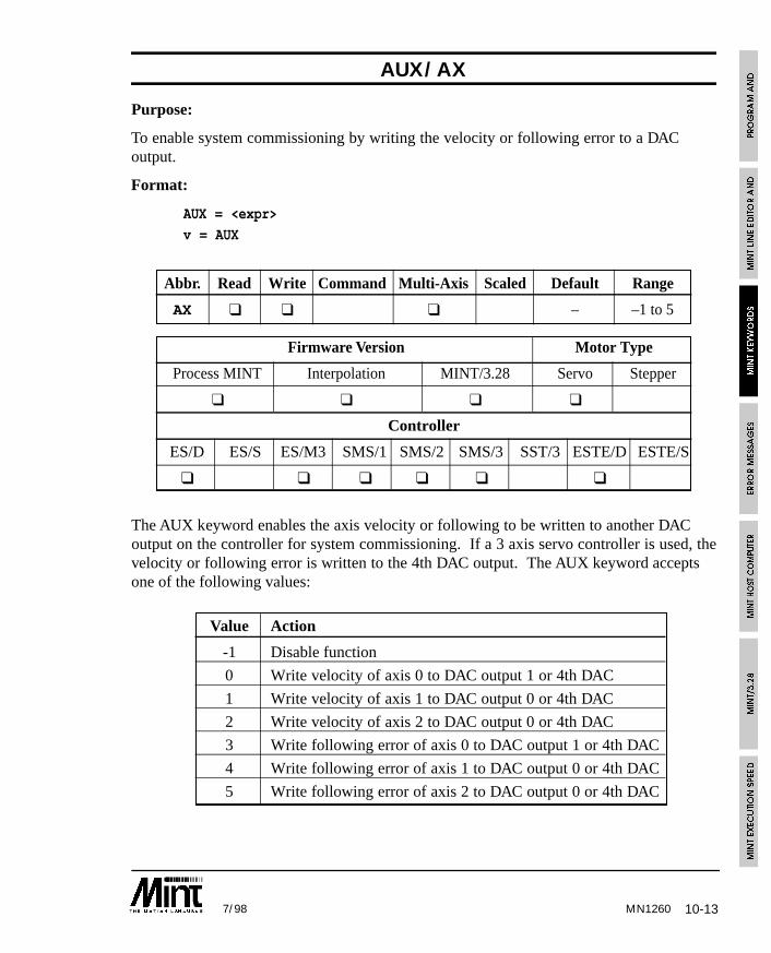
10-137/98 MN1260
AUX/AX
Purpose:
To enable system commissioning by writing the velocity or following error to a DACoutput.
Format:
AUX = <expr>
v = AUX
Abbr. Read Write Command Multi-Axis Scaled Default Range
AX ❑ ❑ ❑ – –1 to 5
Firmware Version Motor Type
Process MINT Interpolation MINT/3.28 Servo Stepper
❑ ❑ ❑ ❑
Controller
ES/D ES/S ES/M3 SMS/1 SMS/2 SMS/3 SST/3 ESTE/D ESTE/S
❑ ❑ ❑ ❑ ❑ ❑
The AUX keyword enables the axis velocity or following to be written to another DACoutput on the controller for system commissioning. If a 3 axis servo controller is used, thevelocity or following error is written to the 4th DAC output. The AUX keyword acceptsone of the following values:
Value Action
-1 Disable function
0 Write velocity of axis 0 to DAC output 1 or 4th DAC
1 Write velocity of axis 1 to DAC output 0 or 4th DAC
2 Write velocity of axis 2 to DAC output 0 or 4th DAC
3 Write following error of axis 0 to DAC output 1 or 4th DAC
4 Write following error of axis 1 to DAC output 0 or 4th DAC
5 Write following error of axis 2 to DAC output 0 or 4th DAC
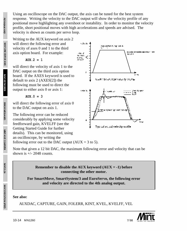
10-14 7/98
Using an oscilloscope on the DAC output, the axis can be tuned for the best systemresponse. Writing the velocity to the DAC output will show the velocity profile of anypositional move highlighting any overshoot or instability. In order to monitor the velocityprofile, short positional moves with high accelerations and speeds are advised. Thevelocity is shown as counts per servo loop.
Writing to the AUX keyword on axis 2will direct the following error andvelocity of axes 0 and 1 to the thirdaxis option board. For example:
AUX.2 = 1
will direct the velocity of axis 1 to theDAC output on the third axis optionboard. If the AXES keyword is used todefault to axis 2 (AXES[2]) thefollowing must be used to direct theoutput to either axis 0 or axis 1:
AUX.0 = 3
will direct the following error of axis 0to the DAC output on axis 1.
The following error can be reducedconsiderably by applying some velocityfeedforward gain, KVELFF (see theGetting Started Guide for furtherdetails). This can be monitored, usingan oscilloscope, by writing thefollowing error out to the DAC output (AUX = 3 to 5).
Note that given a 12 bit DAC, the maximum following error and velocity that can beshown is +/- 2048 counts.
Remember to disable the AUX keyword (AUX = -1) beforeconnecting the other motor.
For SmartMove, SmartSystem/3 and EuroServo, the following errorand velocity are directed to the 4th analog output.
See also:
AUXDAC, CAPTURE, GAIN, FOLERR, KINT, KVEL, KVELFF, VEL
MN1260
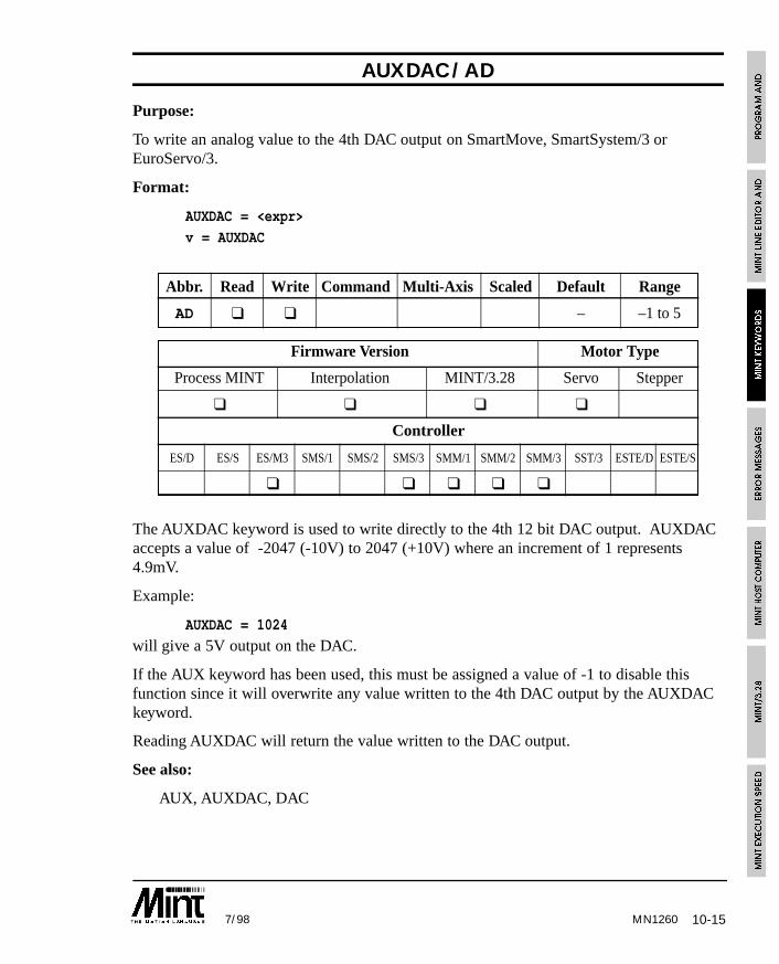
10-157/98 MN1260
AUXDAC/AD
Purpose:
To write an analog value to the 4th DAC output on SmartMove, SmartSystem/3 orEuroServo/3.
Format:
AUXDAC = <expr>
v = AUXDAC
Abbr. Read Write Command Multi-Axis Scaled Default Range
AD ❑ ❑ – –1 to 5
Firmware Version Motor Type
Process MINT Interpolation MINT/3.28 Servo Stepper
❑ ❑ ❑ ❑
Controller
ES/D ES/S ES/M3 SMS/1 SMS/2 SMS/3 SMM/1 SMM/2 SMM/3 SST/3 ESTE/D ESTE/S
❑ ❑ ❑ ❑ ❑
The AUXDAC keyword is used to write directly to the 4th 12 bit DAC output. AUXDACaccepts a value of -2047 (-10V) to 2047 (+10V) where an increment of 1 represents4.9mV.
Example:
AUXDAC = 1024
will give a 5V output on the DAC.
If the AUX keyword has been used, this must be assigned a value of -1 to disable thisfunction since it will overwrite any value written to the 4th DAC output by the AUXDACkeyword.
Reading AUXDAC will return the value written to the DAC output.
See also:
AUX, AUXDAC, DAC
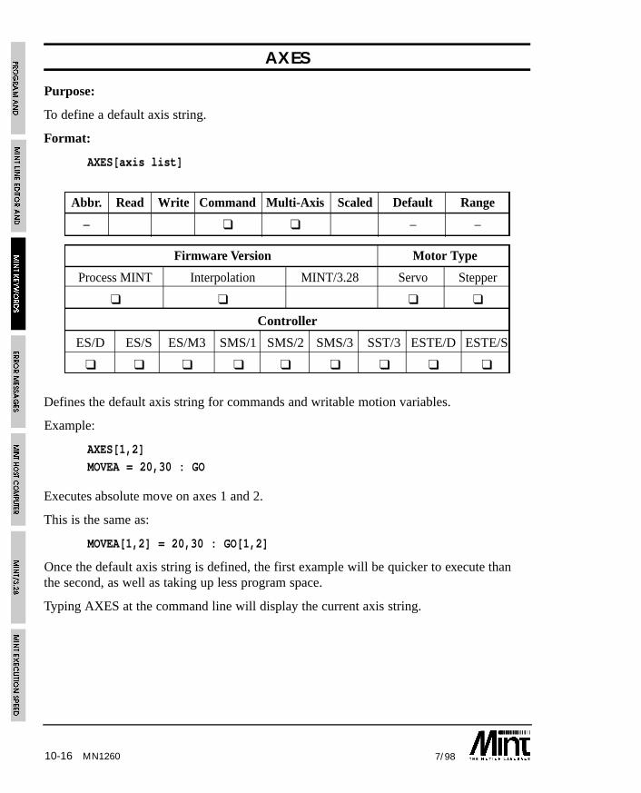
10-16 7/98MN1260
AXES
Purpose:
To define a default axis string.
Format:
AXES[axis list]
Abbr. Read Write Command Multi-Axis Scaled Default Range
– ❑ ❑ – –
Firmware Version Motor Type
Process MINT Interpolation MINT/3.28 Servo Stepper
❑ ❑ ❑ ❑
Controller
ES/D ES/S ES/M3 SMS/1 SMS/2 SMS/3 SST/3 ESTE/D ESTE/S
❑ ❑ ❑ ❑ ❑ ❑ ❑ ❑ ❑
Defines the default axis string for commands and writable motion variables.
Example:
AXES[1,2]
MOVEA = 20,30 : GO
Executes absolute move on axes 1 and 2.
This is the same as:
MOVEA[1,2] = 20,30 : GO[1,2]
Once the default axis string is defined, the first example will be quicker to execute thanthe second, as well as taking up less program space.
Typing AXES at the command line will display the current axis string.
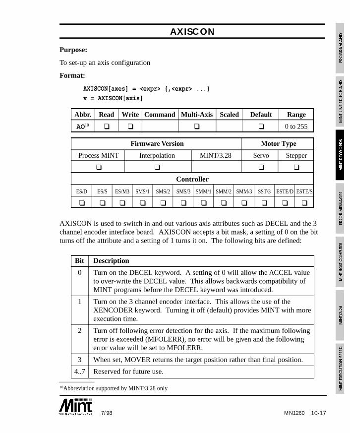
10-177/98 MN1260
10Abbreviation supported by MINT/3.28 only
AXISCON
Purpose:
To set-up an axis configuration
Format:
AXISCON[axes] = <expr> {,<expr> ...}
v = AXISCON[axis]
Abbr. Read Write Command Multi-Axis Scaled Default Range
AO10 ❑ ❑ ❑ ❑ 0 to 255
Firmware Version Motor Type
Process MINT Interpolation MINT/3.28 Servo Stepper
❑ ❑ ❑ ❑
Controller
ES/D ES/S ES/M3 SMS/1 SMS/2 SMS/3 SMM/1 SMM/2 SMM/3 SST/3 ESTE/D ESTE/S
❑ ❑ ❑ ❑ ❑ ❑ ❑ ❑ ❑ ❑ ❑ ❑
AXISCON is used to switch in and out various axis attributes such as DECEL and the 3channel encoder interface board. AXISCON accepts a bit mask, a setting of 0 on the bitturns off the attribute and a setting of 1 turns it on. The following bits are defined:
Bit Description
0 Turn on the DECEL keyword. A setting of 0 will allow the ACCEL valueto over-write the DECEL value. This allows backwards compatibility ofMINT programs before the DECEL keyword was introduced.
1 Turn on the 3 channel encoder interface. This allows the use of theXENCODER keyword. Turning it off (default) provides MINT with moreexecution time.
2 Turn off following error detection for the axis. If the maximum followingerror is exceeded (MFOLERR), no error will be given and the followingerror value will be set to MFOLERR.
3 When set, MOVER returns the target position rather than final position.
4..7 Reserved for future use.
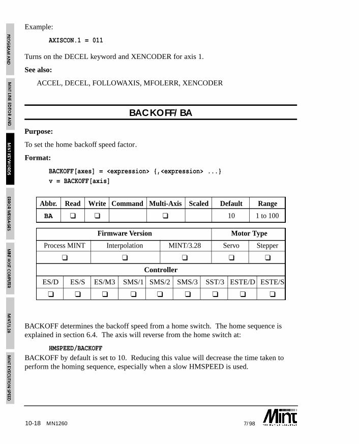
10-18 7/98MN1260
Example:
AXISCON.1 = 011
Turns on the DECEL keyword and XENCODER for axis 1.
See also:
ACCEL, DECEL, FOLLOWAXIS, MFOLERR, XENCODER
BACKOFF/BA
Purpose:
To set the home backoff speed factor.
Format:
BACKOFF[axes] = <expression> {,<expression> ...}
v = BACKOFF[axis]
Abbr. Read Write Command Multi-Axis Scaled Default Range
BA ❑ ❑ ❑ 10 1 to 100
Firmware Version Motor Type
Process MINT Interpolation MINT/3.28 Servo Stepper
❑ ❑ ❑ ❑ ❑
Controller
ES/D ES/S ES/M3 SMS/1 SMS/2 SMS/3 SST/3 ESTE/D ESTE/S
❑ ❑ ❑ ❑ ❑ ❑ ❑ ❑ ❑
BACKOFF determines the backoff speed from a home switch. The home sequence isexplained in section 6.4. The axis will reverse from the home switch at:
HMSPEED/BACKOFF
BACKOFF by default is set to 10. Reducing this value will decrease the time taken toperform the homing sequence, especially when a slow HMSPEED is used.
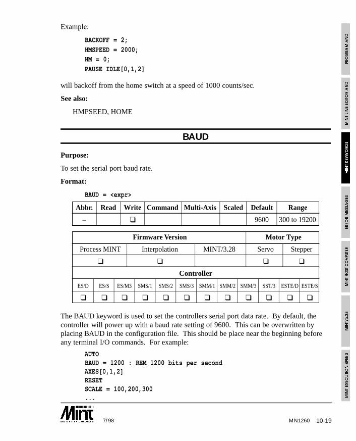
10-197/98 MN1260
Example:
BACKOFF = 2;
HMSPEED = 2000;HM = 0;
PAUSE IDLE[0,1,2]
will backoff from the home switch at a speed of 1000 counts/sec.
See also:
HMPSEED, HOME
BAUD
Purpose:
To set the serial port baud rate.
Format:
BAUD = <expr>
Abbr. Read Write Command Multi-Axis Scaled Default Range
– ❑ 9600 300 to 19200
Firmware Version Motor Type
Process MINT Interpolation MINT/3.28 Servo Stepper
❑ ❑ ❑ ❑
Controller
ES/D ES/S ES/M3 SMS/1 SMS/2 SMS/3 SMM/1 SMM/2 SMM/3 SST/3 ESTE/D ESTE/S
❑ ❑ ❑ ❑ ❑ ❑ ❑ ❑ ❑ ❑ ❑ ❑
The BAUD keyword is used to set the controllers serial port data rate. By default, thecontroller will power up with a baud rate setting of 9600. This can be overwritten byplacing BAUD in the configuration file. This should be place near the beginning beforeany terminal I/O commands. For example:
AUTOBAUD = 1200 : REM 1200 bits per secondAXES[0,1,2]RESETSCALE = 100,200,300...
10-20 7/98
Note that MINT will accept any value of BAUD between the range of 300 and 19,200 andis not restricted to common baud rates such as 1200, 2400, 4800 etc.
BEEP
Purpose:
To issue a beep at the user terminal.
Format:
BEEPIssues a beep at the user terminal. This is useful to attract the attention of an operator. Ifa keypad and display is connected, the keypad buzzer will sound.
Example:
#ONERROR
CLS
? “*** ERROR ***”
REM Beep to attract attention until a key press
REPEAT
BEEP : WAIT = 200
UNTIL INKEYRESET[0,1,2]
RUN
See also:
BEEPOFF, BEEPON, CHR
MN1260
10-217/98
BEEPOFF
Purpose:
To disable the keypad buzzer during INPUT and INKEY. This is the default mode onpower up.
Format:
BEEPOFF
Disable the keypad buzzer during INPUT and INKEY. For example:
BEEPOFF
INPUT a USING 5,2
No beep will be emitted when a key is pressed unlike:
BEEPON
INPUT a USING 5,2
See also:
BEEP, BEEPON, INKEY, INPUT
BEEPON
Purpose:
To enable the keypad buzzer during INPUT and INKEY.
Format:
BEEPON
To provide a form of tactile feedback from the keypad, BEEPON will cause INPUT andINKEY to issue a beep when a key is pressed. Note that on power up, the controller willdefault to BEEPOFF.
Example:
BEEPON
INPUT a USING 5,2
BEEPOFF
A beep will be emitted from the keypad buzzer every time a key is pressed.
See also:
BEEP, BEEPOFF, INKEY, INPUT
MN1260
10-22 7/98
BINARY
Purpose:
To display an 8 bit binary number.
Format:
BINARY argument list
The BINARY keyword has the same syntax as PRINT except numbers are printed inbinary. All numbers are stripped of their fractional part.
Example:
BINARY “12 in binary is : “,12will print:
12 in binary is : 00001100
Numbers will be printed up to 8 bits in length and are prefixed with zeroes wherenecessary. BINARY is useful for reading the digital inputs:
BINARY IN
See also:
BOL, LOCATE, PRINT
BOL
Purpose:
To move the cursor to the beginning of the line.
Format:
BOL
Return the cursor to the Beginning Of Line without feeding a new line. Useful forrepeatedly printing a position (POS) or velocity (VEL) at a terminal on a single line.
Example:
LOOP : ? POS[0]; : BOL : ENDL
Note the use of the semicolon after PRINT to suppress line feeding and to clear anycharacters to the next tab stop.
See also:
LINE, LOCATE, PRINT
MN1260
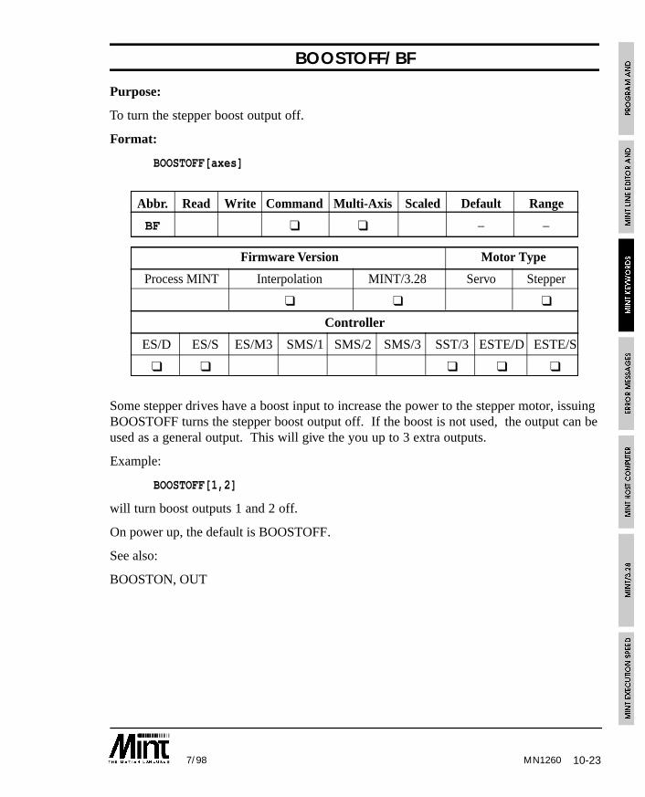
10-237/98 MN1260
BOOSTOFF/BF
Purpose:
To turn the stepper boost output off.
Format:
BOOSTOFF[axes]
Abbr. Read Write Command Multi-Axis Scaled Default Range
BF ❑ ❑ – –
Firmware Version Motor Type
Process MINT Interpolation MINT/3.28 Servo Stepper
❑ ❑ ❑
Controller
ES/D ES/S ES/M3 SMS/1 SMS/2 SMS/3 SST/3 ESTE/D ESTE/S
❑ ❑ ❑ ❑ ❑
Some stepper drives have a boost input to increase the power to the stepper motor, issuingBOOSTOFF turns the stepper boost output off. If the boost is not used, the output can beused as a general output. This will give the you up to 3 extra outputs.
Example:
BOOSTOFF[1,2]
will turn boost outputs 1 and 2 off.
On power up, the default is BOOSTOFF.
See also:
BOOSTON, OUT
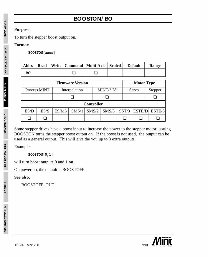
10-24 7/98MN1260
BOOSTON/BO
Purpose:
To turn the stepper boost output on.
Format:
BOOSTON[axes]
Abbr. Read Write Command Multi-Axis Scaled Default Range
BO ❑ ❑ – –
Firmware Version Motor Type
Process MINT Interpolation MINT/3.28 Servo Stepper
❑ ❑ ❑
Controller
ES/D ES/S ES/M3 SMS/1 SMS/2 SMS/3 SST/3 ESTE/D ESTE/S
❑ ❑ ❑ ❑ ❑
Some stepper drives have a boost input to increase the power to the stepper motor, issuingBOOSTON turns the stepper boost output on. If the boost is not used, the output can beused as a general output. This will give the you up to 3 extra outputs.
Example:
BOOSTON[0,1]
will turn boost outputs 0 and 1 on.
On power up, the default is BOOSTOFF.
See also:
BOOSTOFF, OUT
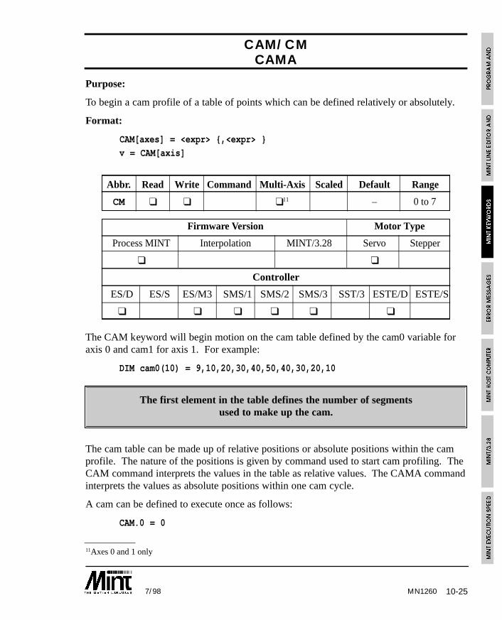
10-257/98 MN1260
11Axes 0 and 1 only
CAM/CMCAMA
Purpose:
To begin a cam profile of a table of points which can be defined relatively or absolutely.
Format:
CAM[axes] = <expr> {,<expr> }
v = CAM[axis]
Abbr. Read Write Command Multi-Axis Scaled Default Range
CM ❑ ❑ ❑11 – 0 to 7
Firmware Version Motor Type
Process MINT Interpolation MINT/3.28 Servo Stepper
❑ ❑
Controller
ES/D ES/S ES/M3 SMS/1 SMS/2 SMS/3 SST/3 ESTE/D ESTE/S
❑ ❑ ❑ ❑ ❑ ❑
The CAM keyword will begin motion on the cam table defined by the cam0 variable foraxis 0 and cam1 for axis 1. For example:
DIM cam0(10) = 9,10,20,30,40,50,40,30,20,10
The first element in the table defines the number of segmentsused to make up the cam.
The cam table can be made up of relative positions or absolute positions within the camprofile. The nature of the positions is given by command used to start cam profiling. TheCAM command interprets the values in the table as relative values. The CAMA commandinterprets the values as absolute positions within one cam cycle.
A cam can be defined to execute once as follows:
CAM.0 = 0
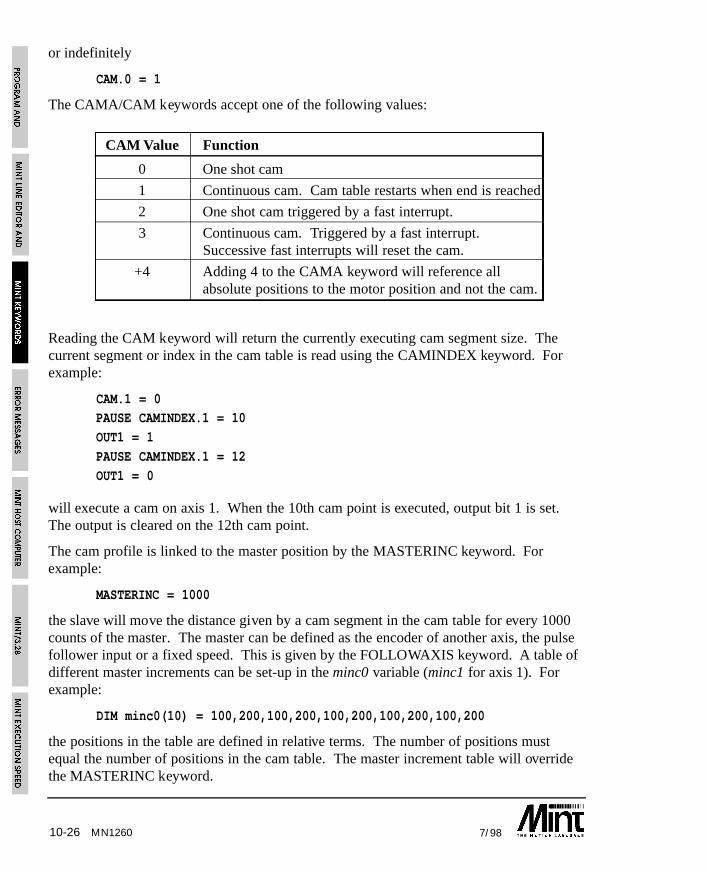
10-26 7/98MN1260
or indefinitely
CAM.0 = 1
The CAMA/CAM keywords accept one of the following values:
CAM Value Function
0 One shot cam
1 Continuous cam. Cam table restarts when end is reached
2 One shot cam triggered by a fast interrupt.
3 Continuous cam. Triggered by a fast interrupt.Successive fast interrupts will reset the cam.
+4 Adding 4 to the CAMA keyword will reference allabsolute positions to the motor position and not the cam.
Reading the CAM keyword will return the currently executing cam segment size. Thecurrent segment or index in the cam table is read using the CAMINDEX keyword. Forexample:
CAM.1 = 0PAUSE CAMINDEX.1 = 10
OUT1 = 1
PAUSE CAMINDEX.1 = 12
OUT1 = 0
will execute a cam on axis 1. When the 10th cam point is executed, output bit 1 is set.The output is cleared on the 12th cam point.
The cam profile is linked to the master position by the MASTERINC keyword. Forexample:
MASTERINC = 1000
the slave will move the distance given by a cam segment in the cam table for every 1000counts of the master. The master can be defined as the encoder of another axis, the pulsefollower input or a fixed speed. This is given by the FOLLOWAXIS keyword. A table ofdifferent master increments can be set-up in the minc0 variable (minc1 for axis 1). Forexample:
DIM minc0(10) = 100,200,100,200,100,200,100,200,100,200
the positions in the table are defined in relative terms. The number of positions mustequal the number of positions in the cam table. The master increment table will overridethe MASTERINC keyword.

10-277/98
Notes:
• The first element in the cam table defines the number of cam segments. This allowsfor greater flexibility in defining different tables.
• When a CAM command is executed, the status display will show a small ‘c’ andMODE will return 16.
• Assigning a value of 0 to a cam segment will cause the slave to wait the measureddistance on the master.
• It is assumed that the master is moving in one direction only.
• Absolute cams have a starting position of 0 within the cam cycle.
• If the MASTERINC value is less than the maximum master input speed (per servoloop closure), the cam will not execute correctly. Ideally the MASTERINC valueshould be at least 5 times the master speed i.e. a cam segment will be executed over 5servo loops. For example:
• Maximum master input speed is 60000 counts per second. With a 2ms loop closuretime, the speed per servo loop is 60000/500 = 120 counts. This would make aminimum MASTERINC value of 600 counts.
• Multiple cam tables can be defined using the CAMSTART and CAMEND keywords.
• Cam profiling is applicable only to axes 0 and 1.
See section 6.7 for further details on cam profiling.
See also:
CAMEND, CAMINDEX, CAMSTART, FLY, FOLLOWAXIS, GEARN, GEARD,MASTERINC, MOVECAM
MN1260
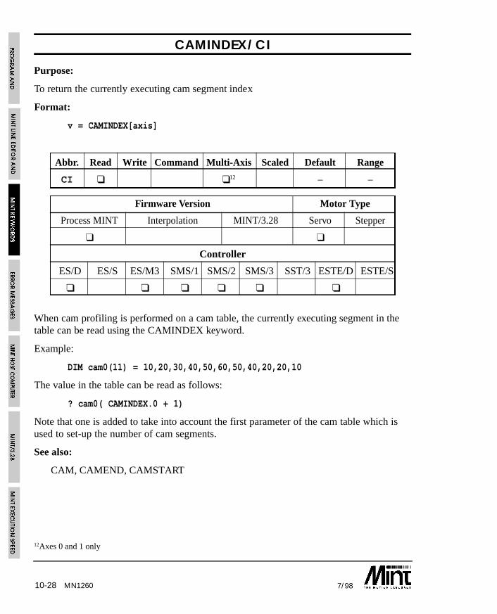
10-28 7/98MN1260
12Axes 0 and 1 only
CAMINDEX/CI
Purpose:
To return the currently executing cam segment index
Format:
v = CAMINDEX[axis]
Abbr. Read Write Command Multi-Axis Scaled Default Range
CI ❑ ❑12 – –
Firmware Version Motor Type
Process MINT Interpolation MINT/3.28 Servo Stepper
❑ ❑
Controller
ES/D ES/S ES/M3 SMS/1 SMS/2 SMS/3 SST/3 ESTE/D ESTE/S
❑ ❑ ❑ ❑ ❑ ❑
When cam profiling is performed on a cam table, the currently executing segment in thetable can be read using the CAMINDEX keyword.
Example:
DIM cam0(11) = 10,20,30,40,50,60,50,40,20,20,10
The value in the table can be read as follows:
? cam0( CAMINDEX.0 + 1)
Note that one is added to take into account the first parameter of the cam table which isused to set-up the number of cam segments.
See also:
CAM, CAMEND, CAMSTART
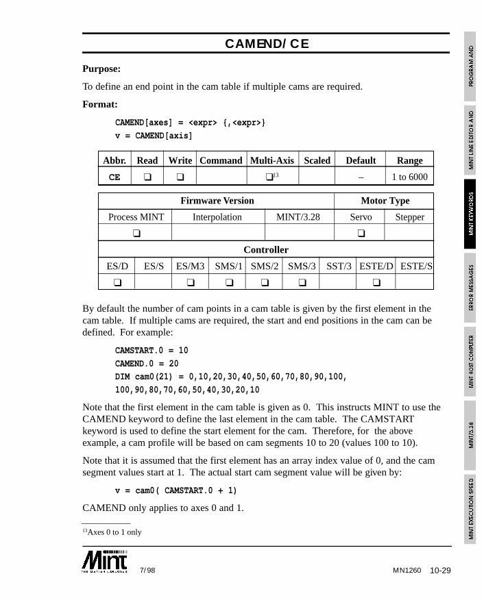
10-297/98 MN1260
13Axes 0 to 1 only
CAMEND/CE
Purpose:
To define an end point in the cam table if multiple cams are required.
Format:
CAMEND[axes] = <expr> {,<expr>}
v = CAMEND[axis]
Abbr. Read Write Command Multi-Axis Scaled Default Range
CE ❑ ❑ ❑13 – 1 to 6000
Firmware Version Motor Type
Process MINT Interpolation MINT/3.28 Servo Stepper
❑ ❑
Controller
ES/D ES/S ES/M3 SMS/1 SMS/2 SMS/3 SST/3 ESTE/D ESTE/S
❑ ❑ ❑ ❑ ❑ ❑
By default the number of cam points in a cam table is given by the first element in thecam table. If multiple cams are required, the start and end positions in the cam can bedefined. For example:
CAMSTART.0 = 10
CAMEND.0 = 20DIM cam0(21) = 0,10,20,30,40,50,60,70,80,90,100,
100,90,80,70,60,50,40,30,20,10
Note that the first element in the cam table is given as 0. This instructs MINT to use theCAMEND keyword to define the last element in the cam table. The CAMSTARTkeyword is used to define the start element for the cam. Therefore, for the aboveexample, a cam profile will be based on cam segments 10 to 20 (values 100 to 10).
Note that it is assumed that the first element has an array index value of 0, and the camsegment values start at 1. The actual start cam segment value will be given by:
v = cam0( CAMSTART.0 + 1)
CAMEND only applies to axes 0 and 1.
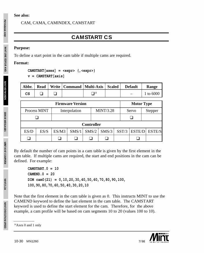
10-30 7/98MN1260
14Axes 0 and 1 only
See also:
CAM, CAMA, CAMINDEX, CAMSTART
CAMSTART/CS
Purpose:
To define a start point in the cam table if multiple cams are required.
Format:
CAMSTART[axes] = <expr> {,<expr>}v = CAMSTART[axis]
Abbr. Read Write Command Multi-Axis Scaled Default Range
CS ❑ ❑ ❑14 – 1 to 6000
Firmware Version Motor Type
Process MINT Interpolation MINT/3.28 Servo Stepper
❑ ❑
Controller
ES/D ES/S ES/M3 SMS/1 SMS/2 SMS/3 SST/3 ESTE/D ESTE/S
❑ ❑ ❑ ❑ ❑ ❑
By default the number of cam points in a cam table is given by the first element in thecam table. If multiple cams are required, the start and end positions in the cam can bedefined. For example:
CAMSTART.0 = 10CAMEND.0 = 20
DIM cam0(21) = 0,10,20,30,40,50,60,70,80,90,100,
100,90,80,70,60,50,40,30,20,10
Note that the first element in the cam table is given as 0. This instructs MINT to use theCAMEND keyword to define the last element in the cam table. The CAMSTARTkeyword is used to define the start element for the cam. Therefore, for the aboveexample, a cam profile will be based on cam segments 10 to 20 (values 100 to 10).

10-317/98 MN1260
Note that it is assumed that the first element has an array index value of 0, and the camsegment values start at 1. The actual start cam segment value will be given bycam0(CAMSTART.0 + 1).
See also:
CAM, CAMA, CAMEND, CAMSTART
CANCEL/CN
Purpose:
To cancel any errors but retain the current position.
Format:
CANCEL[axes]
Abbr. Read Write Command Multi-Axis Scaled Default Range
CN ❑ ❑ – –
Firmware Version Motor Type
Process MINT Interpolation MINT/3.28 Servo Stepper
❑ ❑ ❑ ❑ ❑
Controller
ES/D ES/S ES/M3 SMS/1 SMS/2 SMS/3 SST/3 ESTE/D ESTE/S
❑ ❑ ❑ ❑ ❑ ❑ ❑ ❑ ❑
CANCEL will clear any motion errors and the move in progress but retain the motorposition, unlike RESET. This can be used to recover from errors in an ONERROR routinewith the exception of limit errors. If a limit error exists and the limit is still active, issuinga CANCEL will not clear the error, use the DISLIMIT keyword instead.
CANCEL will also turn contouring off, and reset GEARN and GEARD to 0 and 1respectively. The following error (FOLERR) is set to zero.
On SmartMove, if the outputs are in error, CANCEL will clear all the digital outputs.
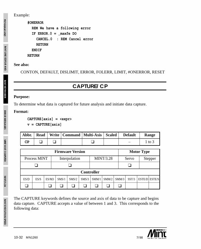
10-32 7/98MN1260
Example:
#ONERROR
REM We have a following errorIF ERROR.0 = _maxfe DO
CANCEL.0 : REM Cancel error
RETURN
ENDIF
RETURN
See also:
CONTON, DEFAULT, DISLIMIT, ERROR, FOLERR, LIMIT, #ONERROR, RESET
CAPTURE/CP
Purpose:
To determine what data is captured for future analysis and initiate data capture.
Format:
CAPTURE[axis] = <expr>
v = CAPTURE[axis]
Abbr. Read Write Command Multi-Axis Scaled Default Range
CP ❑ ❑ ❑ – 1 to 3
Firmware Version Motor Type
Process MINT Interpolation MINT/3.28 Servo Stepper
❑ ❑ ❑
Controller
ES/D ES/S ES/M3 SMS/1 SMS/2 SMS/3 SMM/1 SMM/2 SMM/3 SST/3 ESTE/D ESTE/S
❑ ❑ ❑ ❑ ❑ ❑ ❑ ❑
The CAPTURE keywords defines the source and axis of data to be capture and beginsdata capture. CAPTURE accepts a value of between 1 and 3. This corresponds to thefollowing data:
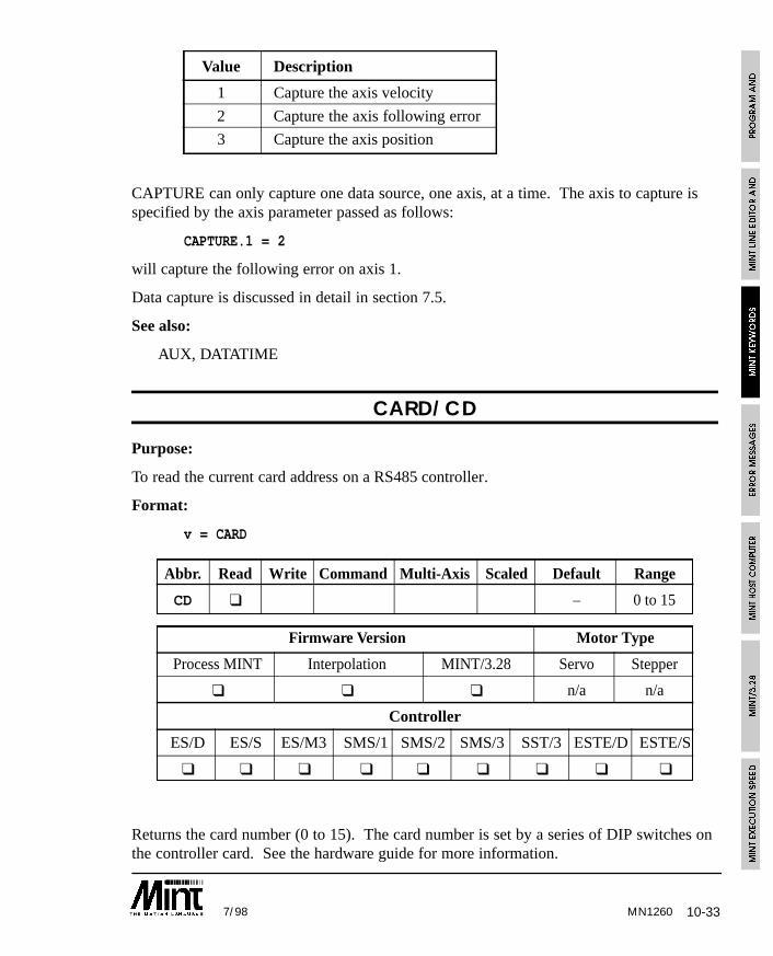
10-337/98 MN1260
Value Description
1 Capture the axis velocity
2 Capture the axis following error
3 Capture the axis position
CAPTURE can only capture one data source, one axis, at a time. The axis to capture isspecified by the axis parameter passed as follows:
CAPTURE.1 = 2
will capture the following error on axis 1.
Data capture is discussed in detail in section 7.5.
See also:
AUX, DATATIME
CARD/CD
Purpose:
To read the current card address on a RS485 controller.
Format:
v = CARD
Abbr. Read Write Command Multi-Axis Scaled Default Range
CD ❑ – 0 to 15
Firmware Version Motor Type
Process MINT Interpolation MINT/3.28 Servo Stepper
❑ ❑ ❑ n/a n/a
Controller
ES/D ES/S ES/M3 SMS/1 SMS/2 SMS/3 SST/3 ESTE/D ESTE/S
❑ ❑ ❑ ❑ ❑ ❑ ❑ ❑ ❑
Returns the card number (0 to 15). The card number is set by a series of DIP switches onthe controller card. See the hardware guide for more information.
10-34 7/98
In a multi-drop system, the CARD keyword can be useful for establishing the controllernumber.
See also:
$ (select controller)
CHR
Purpose:
To print non-ASCII characters. Used in conjunction with PRINT.
Format:
PRINT CHR(<expr>)
CHR is used within the PRINT statement to issue special characters to a terminalemulator.
Example:
PRINT CHR(7)
will issue a beep at the user terminal.
CHR is useful for sending Escape string to a terminal. For example:
PRINT CHR(27),”[1;1”,CHR(27),”[J”,
will home the cursor and clear the screen on a VT100 compatible terminal.
Note the use of the comma to suppress line feeding.
See also:
BINARY, LINE, PRINT
CIRCLEA/CA
Purpose:
To perform a circular move with absolute co-ordinates.
Format:
CIRCLEA[axis0,axis1] = <centre0>,<centre1>,<angle>
MN1260
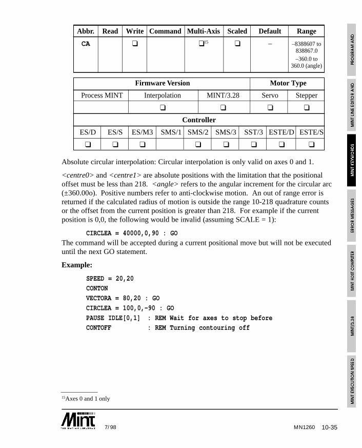
10-357/98 MN1260
15Axes 0 and 1 only
Abbr. Read Write Command Multi-Axis Scaled Default Range
CA ❑ ❑15 ❑ – –8388607 to838867.0–360.0 to
360.0 (angle)
Firmware Version Motor Type
Process MINT Interpolation MINT/3.28 Servo Stepper
❑ ❑ ❑ ❑
Controller
ES/D ES/S ES/M3 SMS/1 SMS/2 SMS/3 SST/3 ESTE/D ESTE/S
❑ ❑ ❑ ❑ ❑ ❑ ❑ ❑
Absolute circular interpolation: Circular interpolation is only valid on axes 0 and 1.
<centre0> and <centre1> are absolute positions with the limitation that the positionaloffset must be less than 218. <angle> refers to the angular increment for the circular arc(±360.00o). Positive numbers refer to anti-clockwise motion. An out of range error isreturned if the calculated radius of motion is outside the range 10-218 quadrature countsor the offset from the current position is greater than 218. For example if the currentposition is 0,0, the following would be invalid (assuming SCALE = 1):
CIRCLEA = 40000,0,90 : GO
The command will be accepted during a current positional move but will not be executeduntil the next GO statement.
Example:
SPEED = 20,20CONTON
VECTORA = 80,20 : GO
CIRCLEA = 100,0,-90 : GO
PAUSE IDLE[0,1] : REM Wait for axes to stop beforeCONTOFF : REM Turning contouring off
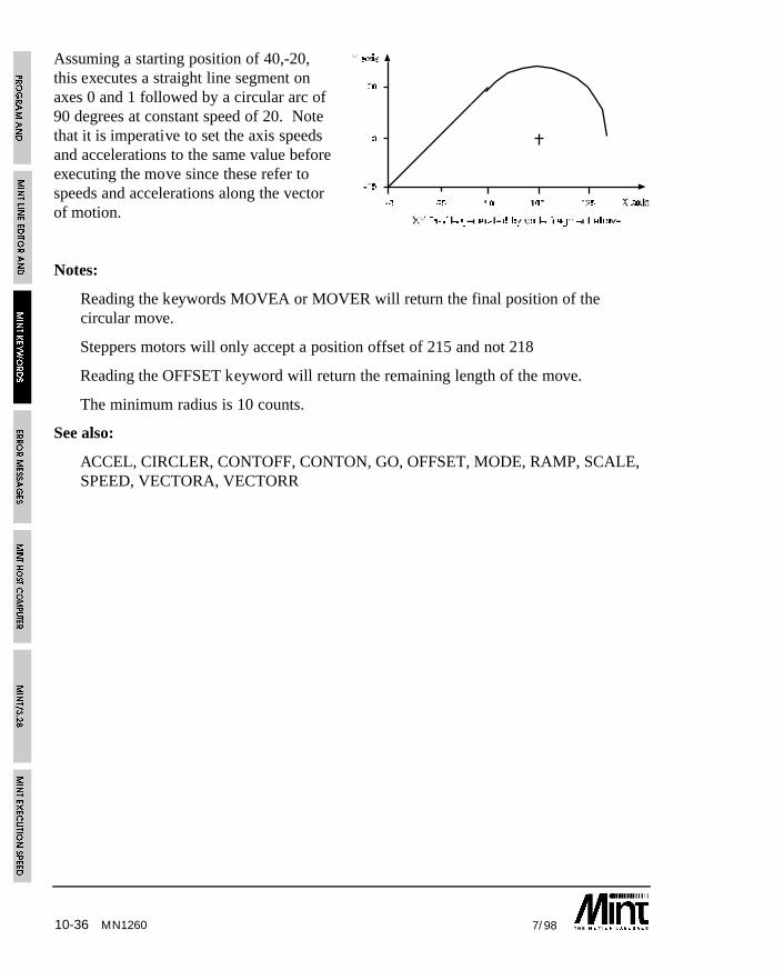
10-36 7/98
Assuming a starting position of 40,-20,this executes a straight line segment onaxes 0 and 1 followed by a circular arc of90 degrees at constant speed of 20. Notethat it is imperative to set the axis speedsand accelerations to the same value beforeexecuting the move since these refer tospeeds and accelerations along the vectorof motion.
Notes:
Reading the keywords MOVEA or MOVER will return the final position of thecircular move.
Steppers motors will only accept a position offset of 215 and not 218
Reading the OFFSET keyword will return the remaining length of the move.
The minimum radius is 10 counts.
See also:
ACCEL, CIRCLER, CONTOFF, CONTON, GO, OFFSET, MODE, RAMP, SCALE, SPEED, VECTORA, VECTORR
MN1260
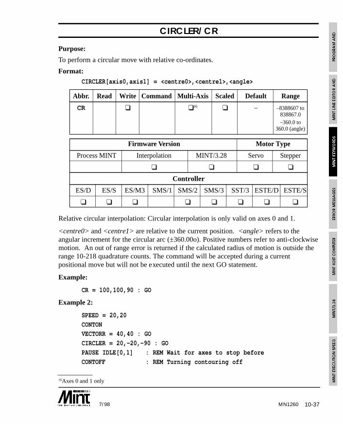
10-377/98 MN1260
16Axes 0 and 1 only
CIRCLER/CR
Purpose:
To perform a circular move with relative co-ordinates.
Format: CIRCLER[axis0,axis1] = <centre0>,<centre1>,<angle>
Abbr. Read Write Command Multi-Axis Scaled Default Range
CR ❑ ❑16 ❑ – –8388607 to838867.0–360.0 to
360.0 (angle)
Firmware Version Motor Type
Process MINT Interpolation MINT/3.28 Servo Stepper
❑ ❑ ❑ ❑
Controller
ES/D ES/S ES/M3 SMS/1 SMS/2 SMS/3 SST/3 ESTE/D ESTE/S
❑ ❑ ❑ ❑ ❑ ❑ ❑ ❑
Relative circular interpolation: Circular interpolation is only valid on axes 0 and 1.
<centre0> and <centre1> are relative to the current position. <angle> refers to theangular increment for the circular arc (±360.00o). Positive numbers refer to anti-clockwisemotion. An out of range error is returned if the calculated radius of motion is outside therange 10-218 quadrature counts. The command will be accepted during a currentpositional move but will not be executed until the next GO statement.
Example:
CR = 100,100,90 : GO
Example 2:
SPEED = 20,20
CONTONVECTORR = 40,40 : GO
CIRCLER = 20,-20,-90 : GO
PAUSE IDLE[0,1] : REM Wait for axes to stop before
CONTOFF : REM Turning contouring off
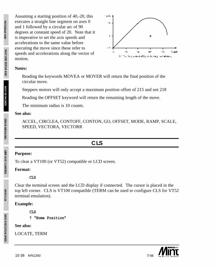
10-38 7/98
Assuming a starting position of 40,-20, thisexecutes a straight line segment on axes 0and 1 followed by a circular arc of 90degrees at constant speed of 20. Note that itis imperative to set the axis speeds andaccelerations to the same value beforeexecuting the move since these refer tospeeds and accelerations along the vector ofmotion.
Notes:
Reading the keywords MOVEA or MOVER will return the final position of thecircular move.
Steppers motors will only accept a maximum position offset of 215 and not 218
Reading the OFFSET keyword will return the remaining length of the move.
The minimum radius is 10 counts.
See also:
ACCEL, CIRCLEA, CONTOFF, CONTON, GO, OFFSET, MODE, RAMP, SCALE,SPEED, VECTORA, VECTORR
CLS
Purpose:
To clear a VT100 (or VT52) compatible or LCD screen.
Format:
CLS
Clear the terminal screen and the LCD display if connected. The cursor is placed in thetop left corner. CLS is VT100 compatible (TERM can be used to configure CLS for VT52terminal emulation).
Example:
CLS
? “Home Position”
See also:
LOCATE, TERM
MN1260
10-397/98
COMMSOFF
Purpose:
To turn protected communications protocol off.
Format:
COMMSOFF
Turns the protected communications protocol off allowing the serial port to be used tostandard I/O statements such as PRINT and INPUT.
See also:
COMMSON, DIM
COMMSON
Purpose:
To turn protected communications protocol on.
Format:
COMMSON
Turns the protected communications protocol on. COMMSON will make MINT aware ofprotected data packets. Issuing COMMSON will automatically define an array variableCOMMS which is 99 elements in length. This must be placed before any DIM statementsfor correct execution. For example:
COMMSONDIM xpos(100)
DIM ypos(100)
COMMSON will disable Ctrl-E until COMMSON is terminated by sending a special datapacket.
COMMSON cannot be issued at the command line.
Subsequent uses of COMMSON will turn the protected protocol on and can be used inconjunction with COMMSOFF to turns communications on and off from within theprogram.
See section 12 on protected communications for full details.
See also:
COMMSOFF, DIM
MN1260
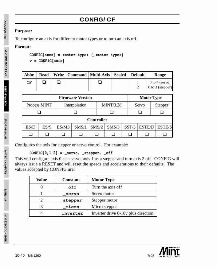
10-40 7/98MN1260
CONFIG/CF
Purpose:
To configure an axis for different motor types or to turn an axis off.
Format:
CONFIG[axes] = <motor type> {,<motor type>}
v = CONFIG[axis]
Abbr. Read Write Command Multi-Axis Scaled Default Range
CF ❑ ❑ ❑ 1 0 to 4 (servo)2 0 to 3 (stepper)
Firmware Version Motor Type
Process MINT Interpolation MINT/3.28 Servo Stepper
❑ ❑ ❑ ❑ ❑
Controller
ES/D ES/S ES/M3 SMS/1 SMS/2 SMS/3 SST/3 ESTE/D ESTE/S
❑ ❑ ❑ ❑ ❑ ❑ ❑ ❑ ❑
Configures the axis for stepper or servo control. For example:
CONFIG[0,1,2] = _servo, _stepper, _off
This will configure axis 0 as a servo, axis 1 as a stepper and turn axis 2 off. CONFIG willalways issue a RESET and will reset the speeds and accelerations to their defaults. Thevalues accepted by CONFIG are:
Value Constant Motor Type
0 _off Turn the axis off
1 _servo Servo motor
2 _stepper Stepper motor
3 _micro Micro stepper
4 _inverter Inverter drive 0-10v plus direction
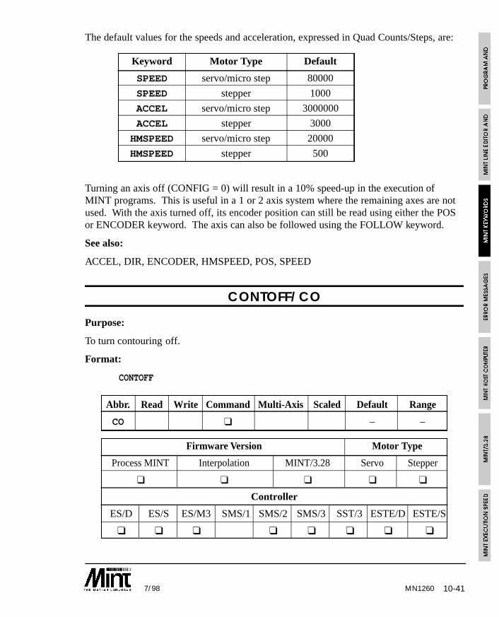
10-417/98 MN1260
The default values for the speeds and acceleration, expressed in Quad Counts/Steps, are:
Keyword Motor Type Default
SPEED servo/micro step 80000
SPEED stepper 1000
ACCEL servo/micro step 3000000
ACCEL stepper 3000
HMSPEED servo/micro step 20000
HMSPEED stepper 500
Turning an axis off (CONFIG = 0) will result in a 10% speed-up in the execution ofMINT programs. This is useful in a 1 or 2 axis system where the remaining axes are notused. With the axis turned off, its encoder position can still be read using either the POSor ENCODER keyword. The axis can also be followed using the FOLLOW keyword.
See also:
ACCEL, DIR, ENCODER, HMSPEED, POS, SPEED
CONTOFF/CO
Purpose:
To turn contouring off.
Format:
CONTOFF
Abbr. Read Write Command Multi-Axis Scaled Default Range
CO ❑ – –
Firmware Version Motor Type
Process MINT Interpolation MINT/3.28 Servo Stepper
❑ ❑ ❑ ❑ ❑
Controller
ES/D ES/S ES/M3 SMS/1 SMS/2 SMS/3 SST/3 ESTE/D ESTE/S
❑ ❑ ❑ ❑ ❑ ❑ ❑ ❑
10-42 7/98MN1260
Sets contouring off at the end of a coordinated motion sequence.
Example:
SPEED = 20,20
CONTONVECTORR = 40,40 : GO
CIRCLER = 20,-20,-90 : GO
PAUSE IDLE[0,1]
CONTOFF
Execute a straight line segment on axes 0 and 1 followed by a circular arc of 90 degrees ata constant speed of 20.
See also:
CONTON
CONTON/CT
Purpose:
To turn contouring on.
Format:
CONTON
Abbr. Read Write Command Multi-Axis Scaled Default Range
CT ❑ – –
Firmware Version Motor Type
Process MINT Interpolation MINT/3.28 Servo Stepper
❑ ❑ ❑ ❑ ❑
Controller
ES/D ES/S ES/M3 SMS/1 SMS/2 SMS/3 SST/3 ESTE/D ESTE/S
❑ ❑ ❑ ❑ ❑ ❑ ❑ ❑
Sets contouring on for the specified axes. This allows a coordinated positional motionsequence to be executed without slowing down at the end of each move. Only valid whena move is not in progress.
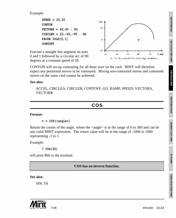
10-437/98
Example:
SPEED = 20,20
CONTONVECTORR = 40,40 : GO
CIRCLER = 20,-20,-90 : GO
PAUSE IDLE[0,1]
CONTOFF
Execute a straight line segment on axes0 and 1 followed by a circular arc of 90degrees at a constant speed of 20.
CONTON will set-up contouring for all three axes on the card. MINT will thereforeexpect any positional moves to be contoured. Mixing non-contoured moves and contouredmoves on the same card cannot be achieved.
See also:
ACCEL, CIRCLEA, CIRCLER, CONTOFF, GO, RAMP, SPEED, VECTORA,VECTORR
COS
Format:
v = COS(<angle>)
Return the cosine of the angle, where the <angle> is in the range of 0 to 360 and can beany valid MINT expression. The return value will be in the range of -1000 to 1000representing -1 to 1.
Example:
? COS(30)
will print 866 to the terminal.
COS has no inverse function.
See also:
SIN, TA
MN1260
10-44 7/98MN1260
CURRLIMIT/CL
Purpose:
To restrict the DAC output voltage to within a defined range.
Format:
CURRLIMIT[axes] = <expression> {,<expression> ...}
v = CURRLIMIT[axis]
Abbr. Read Write Command Multi-Axis Scaled Default Range
CL ❑ ❑ ❑ 100 1 to 100.0
Firmware Version Motor Type
Process MINT Interpolation MINT/3.28 Servo Stepper
❑ ❑ ❑ ❑
Controller
ES/D ES/S ES/M3 SMS/1 SMS/2 SMS/3 SST/3 ESTE/D ESTE/S
❑ ❑ ❑ ❑ ❑ ❑
CURRLIMIT restricts the output voltage of the DAC output. A value of 50 (%) will limitthe DAC output to ±5V. For example:
CURRLIMIT[0,1,2] = 50,50,60
will set the current limit of axes 0 and 1 to 50% and axis 2 to 60%.
CURRLIMIT is only applicable to current amplifiers. Using CURRLIMIT with velocityamplifiers will only restrict the maximum velocity.
See also:
DAC, DEMAND, KINTRANGE
10-457/98 MN1260
DAC/DC
Purpose:
To write a value to the 12bit DAC.
Format:
DAC[axes] = <expression> {,<expression> ...}
v = DAC[axis]
Abbr. Read Write Command Multi-Axis Scaled Default Range
DC ❑ ❑ ❑ – -2047 to2047
Firmware Version Motor Type
Process MINT Interpolation MINT/3.28 Servo Stepper
❑ ❑ ❑ ❑
Controller
ES/D ES/S ES/M3 SMS/1 SMS/2 SMS/3 SST/3 ESTE/D ESTE/S
❑ ❑ ❑ ❑ ❑ ❑
DAC is used to write directly to the 12 bit DAC output. The axis must first be eitherturned off or configured for stepper mode i.e.
CONFIG.0 = _offDAC.0 = -1024
or:
CONFIG.0 = _stepper
DAC.0 = -1024
will give -5V output on the DAC.
Reading DAC in servo mode will return the current DAC value in the range of -2047 to+2047.
DAC is similar to TORQUE mode but provides for more accurate control over the DACoutput.
See also:
AUXDAC, CONFIG, DEMAND

10-46 7/98MN1260
DATATIME/DT
Purpose:
To specify the time over which data capture occurs
Format:
DATATIME = <expr>
v = DATATIME
Abbr. Read Write Command Multi-Axis Scaled Default Range
DT ❑ ❑ – 0 to 32000
Firmware Version Motor Type
Process MINT Interpolation MINT/3.28 Servo Stepper
❑ ❑ ❑
Controller
ES/D ES/S ES/M3 SMS/1 SMS/2 SMS/3 SMM/1 SMM/2 SMM/3 SST/3 ESTE/D ESTE/S
❑ ❑ ❑ ❑ ❑ ❑ ❑ ❑
DATATIME specifies the time in milli-seconds over which data capture will occur.DATATIME should be called prior to the first call to CAPTURE.
Reading DATATIME will return the remaining capture time.
Data capture is discussed in detail in section 7.5.
See also:
AUX, CAPTURE
DECEL/DE
Purpose:
To set a deceleration rate on the axis.
Format:
DECEL[axes] = <expr> {,<expr> ...}
v = DECEL[axis]
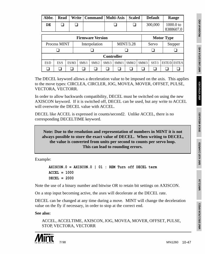
10-477/98 MN1260
Abbr. Read Write Command Multi-Axis Scaled Default Range
DE ❑ ❑ ❑ ❑ 300,000 1000.0 to8388607.0
Firmware Version Motor Type
Process MINT Interpolation MINT/3.28 Servo Stepper
❑ ❑ ❑ ❑ ❑
Controller
ES/D ES/S ES/M3 SMS/1 SMS/2 SMS/3 SMM/1 SMM/2 SMM/3 SST/3 ESTE/D ESTE/S
❑ ❑ ❑ ❑ ❑ ❑ ❑ ❑ ❑ ❑ ❑ ❑
The DECEL keyword allows a deceleration value to be imposed on the axis. This appliesto the move types: CIRCLEA, CIRCLER, JOG, MOVEA, MOVER, OFFSET, PULSE,VECTORA, VECTORR.
In order to allow backwards compatibility, DECEL must be switched on using the newAXISCON keyword. If it is switched off, DECEL can be used, but any write to ACCELwill overwrite the DECEL value with ACCEL.
DECEL like ACCEL is expressed in counts/second2. Unlike ACCEL, there is nocorresponding DECELTIME keyword.
Note: Due to the resolution and representation of numbers in MINT it is notalways possible to store the exact value of DECEL. When writing to DECEL,
the value is converted from units per second to counts per servo loop.This can lead to rounding errors.
Example:
AXISCON.0 = AXISCON.0 | 01 : REM Turn off DECEL termACCEL = 1000
DECEL = 2000
Note the use of a binary number and bitwise OR to retain bit settings on AXISCON.
On a stop input becoming active, the axes will decelerate at the DECEL rate.
DECEL can be changed at any time during a move. MINT will change the decelerationvalue on the fly if necessary, in order to stop at the correct end.
See also:
ACCEL, ACCELTIME, AXISCON, JOG, MOVEA, MOVER, OFFSET, PULSE,STOP, VECTORA, VECTORR
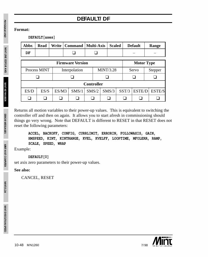
10-48 7/98MN1260
DEFAULT/DF
Format:
DEFAULT[axes]
Abbr. Read Write Command Multi-Axis Scaled Default Range
DF ❑ ❑ – –
Firmware Version Motor Type
Process MINT Interpolation MINT/3.28 Servo Stepper
❑ ❑ ❑ ❑ ❑
Controller
ES/D ES/S ES/M3 SMS/1 SMS/2 SMS/3 SST/3 ESTE/D ESTE/S
❑ ❑ ❑ ❑ ❑ ❑ ❑ ❑ ❑
Returns all motion variables to their power-up values. This is equivalent to switching thecontroller off and then on again. It allows you to start afresh in commissioning shouldthings go very wrong. Note that DEFAULT is different to RESET in that RESET does notreset the following parameters:
ACCEL, BACKOFF, CONFIG, CURRLIMIT, ERRORIN, FOLLOWAXIS, GAIN,HMSPEED, KINT, KINTRANGE, KVEL, KVELFF, LOOPTIME, MFOLERR, RAMP,SCALE, SPEED, WRAP
Example:
DEFAULT[0]
set axis zero parameters to their power-up values.
See also:
CANCEL, RESET
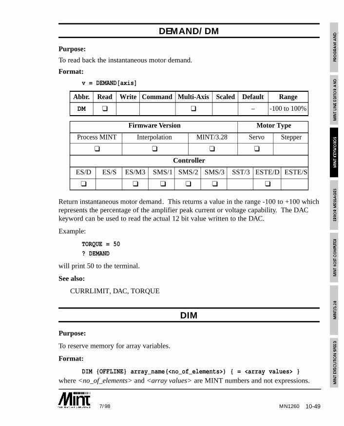
10-497/98 MN1260
DEMAND/DM
Purpose:
To read back the instantaneous motor demand.
Format:
v = DEMAND[axis]
Abbr. Read Write Command Multi-Axis Scaled Default Range
DM ❑ ❑ – -100 to 100%
Firmware Version Motor Type
Process MINT Interpolation MINT/3.28 Servo Stepper
❑ ❑ ❑ ❑
Controller
ES/D ES/S ES/M3 SMS/1 SMS/2 SMS/3 SST/3 ESTE/D ESTE/S
❑ ❑ ❑ ❑ ❑ ❑
Return instantaneous motor demand. This returns a value in the range -100 to +100 whichrepresents the percentage of the amplifier peak current or voltage capability. The DACkeyword can be used to read the actual 12 bit value written to the DAC.
Example:
TORQUE = 50
? DEMAND
will print 50 to the terminal.
See also:
CURRLIMIT, DAC, TORQUE
DIM
Purpose:
To reserve memory for array variables.
Format:
DIM {OFFLINE} array_name(<no_of_elements>) { = <array values> }
where <no_of_elements> and <array values> are MINT numbers and not expressions.
10-50 7/98MN1260
Reserves data space for array variables and optionally initializes them. Example:
DIM my_array(100)
declares an array variable called my_array with one hundred elements.
DIM y_position(10) = 1,2,3,4,5,6,7,8,9,10
declares an array y_position, where the first element, y_position(1), is equal to 1, secondequal to 2 etc.
The array variable name can also be used as a normal variable. For example:
y_position = 1
will treat y_position as a standard variable.
Data can also be reserved to reside on a memory card using the OFFLINE keyword. Forexample:
DIM OFFLINE myData(100)
See section 4.5 on array data for more detail on the use of DIM.
Notes:
DIM cannot be used on the command line.
The COMMSON keyword, used to enable protected protocol mode, will automaticallycreate a 99 element array with the variable name comms. COMMSON must be placedbefore any DIM statements.
Expressions or variables cannot be used in the array declaration. The following willall result in an error:
DIM myData(x)
DIM myData2( 3 ) = a,a+1,b+2
Character constants can be used in an array declaration:
DIM funcKey(6) = ‘A’, ‘B’, ‘C’, ‘D’, ‘E’, ‘F’
See also:
COMMSON, DISPLAY, FREE, LOAD, OFFLINE, RELEASE, SAVE
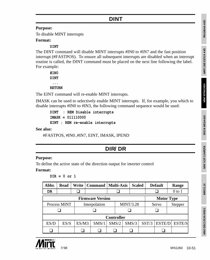
10-517/98 MN1260
DINTPurpose:To disable MINT interruptsFormat:
DINTThe DINT command will disable MINT interrupts #IN0 to #IN7 and the fast positioninterrupt (#FASTPOS). To ensure all subsequent interrupts are disabled when an interruptroutine is called, the DINT command must be placed on the next line following the label.For example:
#IN0DINT...
RETURN
The EINT command will re-enable MINT interrupts.
IMASK can be used to selectively enable MINT interrupts. If, for example, you which todisable interrupts #IN0 to #IN3, the following command sequence would be used:
DINT : REM Disable interruptsIMASK = 011110000EINT : REM re-enable interrupts
See also:#FASTPOS, #IN0..#IN7, EINT, IMASK, IPEND
DIR/DRPurpose:To define the active state of the direction output for inverter control
Format:DIR = 0 or 1
Abbr. Read Write Command Multi-Axis Scaled Default RangeDR ❑ ❑ ❑ 0 to 1
Firmware Version Motor TypeProcess MINT Interpolation MINT/3.28 Servo Stepper
❑ ❑ ❑ ❑
ControllerES/D ES/S ES/M3 SMS/1 SMS/2 SMS/3 SST/3 ESTE/D ESTE/S
❑ ❑ ❑ ❑ ❑ ❑
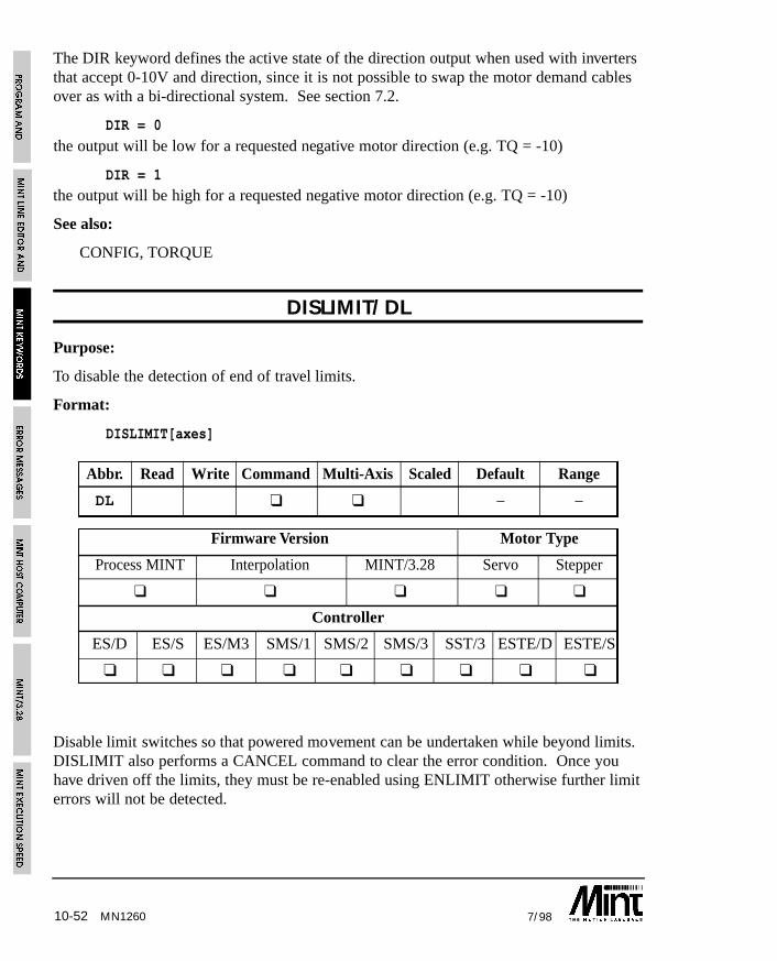
10-52 7/98MN1260
The DIR keyword defines the active state of the direction output when used with invertersthat accept 0-10V and direction, since it is not possible to swap the motor demand cablesover as with a bi-directional system. See section 7.2.
DIR = 0
the output will be low for a requested negative motor direction (e.g. TQ = -10)
DIR = 1the output will be high for a requested negative motor direction (e.g. TQ = -10)
See also:
CONFIG, TORQUE
DISLIMIT/DL
Purpose:
To disable the detection of end of travel limits.
Format:
DISLIMIT[axes]
Abbr. Read Write Command Multi-Axis Scaled Default Range
DL ❑ ❑ – –
Firmware Version Motor Type
Process MINT Interpolation MINT/3.28 Servo Stepper
❑ ❑ ❑ ❑ ❑
Controller
ES/D ES/S ES/M3 SMS/1 SMS/2 SMS/3 SST/3 ESTE/D ESTE/S
❑ ❑ ❑ ❑ ❑ ❑ ❑ ❑ ❑
Disable limit switches so that powered movement can be undertaken while beyond limits.DISLIMIT also performs a CANCEL command to clear the error condition. Once youhave driven off the limits, they must be re-enabled using ENLIMIT otherwise further limiterrors will not be detected.
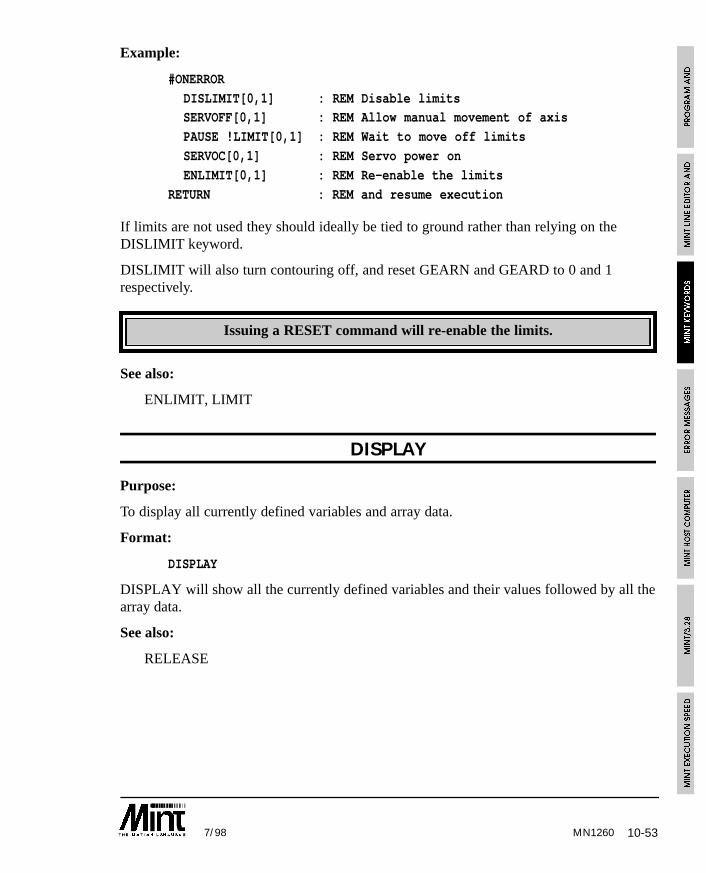
10-537/98 MN1260
Example:
#ONERROR
DISLIMIT[0,1] : REM Disable limitsSERVOFF[0,1] : REM Allow manual movement of axis
PAUSE !LIMIT[0,1] : REM Wait to move off limits
SERVOC[0,1] : REM Servo power on
ENLIMIT[0,1] : REM Re-enable the limits
RETURN : REM and resume execution
If limits are not used they should ideally be tied to ground rather than relying on theDISLIMIT keyword.
DISLIMIT will also turn contouring off, and reset GEARN and GEARD to 0 and 1respectively.
Issuing a RESET command will re-enable the limits.
See also:
ENLIMIT, LIMIT
DISPLAY
Purpose:
To display all currently defined variables and array data.
Format:
DISPLAY
DISPLAY will show all the currently defined variables and their values followed by all thearray data.
See also:
RELEASE
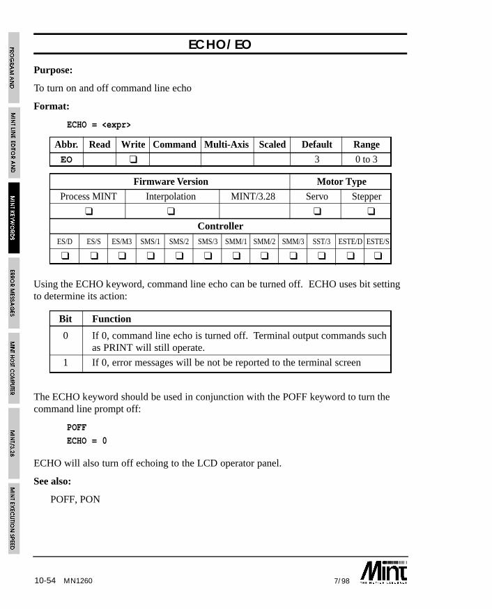
10-54 7/98MN1260
ECHO/EO
Purpose:
To turn on and off command line echo
Format:
ECHO = <expr>
Abbr. Read Write Command Multi-Axis Scaled Default Range
EO ❑ 3 0 to 3
Firmware Version Motor Type
Process MINT Interpolation MINT/3.28 Servo Stepper
❑ ❑ ❑ ❑
Controller
ES/D ES/S ES/M3 SMS/1 SMS/2 SMS/3 SMM/1 SMM/2 SMM/3 SST/3 ESTE/D ESTE/S
❑ ❑ ❑ ❑ ❑ ❑ ❑ ❑ ❑ ❑ ❑ ❑
Using the ECHO keyword, command line echo can be turned off. ECHO uses bit settingto determine its action:
Bit Function
0 If 0, command line echo is turned off. Terminal output commands suchas PRINT will still operate.
1 If 0, error messages will be not be reported to the terminal screen
The ECHO keyword should be used in conjunction with the POFF keyword to turn thecommand line prompt off:
POFF
ECHO = 0
ECHO will also turn off echoing to the LCD operator panel.
See also:
POFF, PON
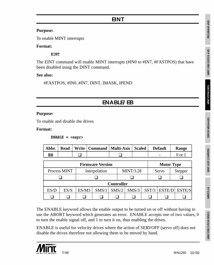
10-557/98 MN1260
EINT
Purpose:
To enable MINT interrupts
Format:
EINT
The EINT command will enable MINT interrupts (#IN0 to #IN7, #FASTPOS) that havebeen disabled using the DINT command.
See also:
#FASTPOS, #IN0..#IN7, DINT, IMASK, IPEND
ENABLE/EB
Purpose:
To enable and disable the drives
Format:
ENABLE = <expr>
Abbr. Read Write Command Multi-Axis Scaled Default Range
EB ❑ ❑ – 0 or 1
Firmware Version Motor Type
Process MINT Interpolation MINT/3.28 Servo Stepper
❑ ❑ ❑ ❑ ❑
Controller
ES/D ES/S ES/M3 SMS/1 SMS/2 SMS/3 SST/3 ESTE/D ESTE/S
❑ ❑ ❑ ❑ ❑ ❑ ❑ ❑ ❑
The ENABLE keyword allows the enable output to be turned on or off without having touse the ABORT keyword which generates an error. ENABLE accepts one of two values, 0to turn the enable signal off, and 1 to turn it on, thus enabling the drives.
ENABLE is useful for velocity drives where the action of SERVOFF (servo off) does notdisable the drives therefore not allowing them to be moved by hand.
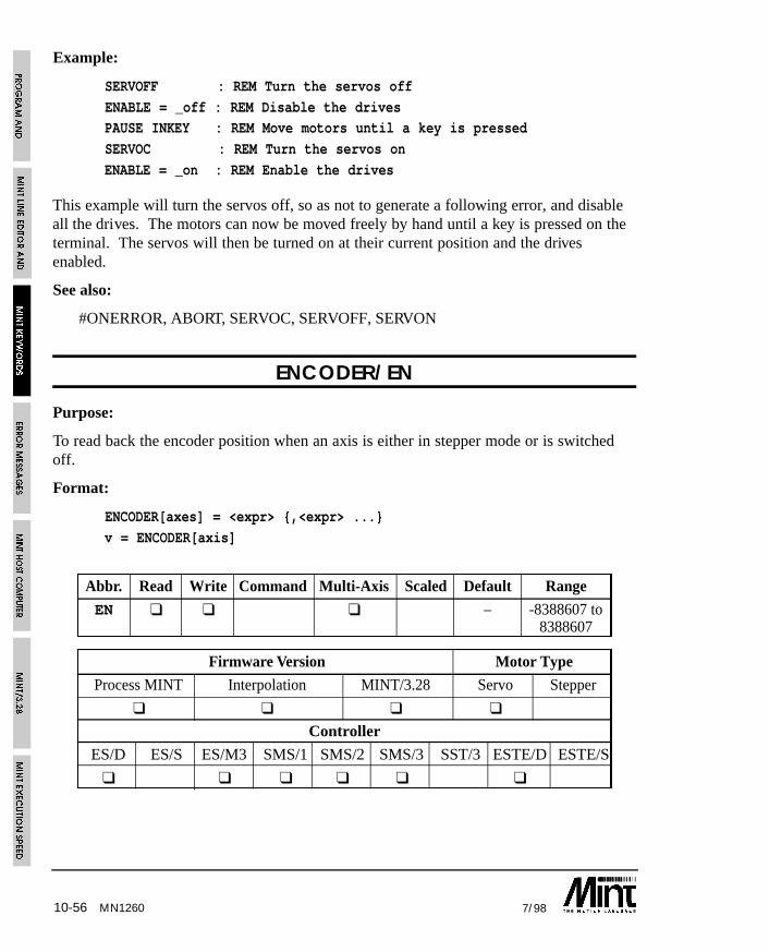
10-56 7/98MN1260
Example:
SERVOFF : REM Turn the servos off
ENABLE = _off : REM Disable the drivesPAUSE INKEY : REM Move motors until a key is pressed
SERVOC : REM Turn the servos on
ENABLE = _on : REM Enable the drives
This example will turn the servos off, so as not to generate a following error, and disableall the drives. The motors can now be moved freely by hand until a key is pressed on theterminal. The servos will then be turned on at their current position and the drivesenabled.
See also:
#ONERROR, ABORT, SERVOC, SERVOFF, SERVON
ENCODER/EN
Purpose:
To read back the encoder position when an axis is either in stepper mode or is switchedoff.
Format:
ENCODER[axes] = <expr> {,<expr> ...}
v = ENCODER[axis]
Abbr. Read Write Command Multi-Axis Scaled Default Range
EN ❑ ❑ ❑ – -8388607 to8388607
Firmware Version Motor Type
Process MINT Interpolation MINT/3.28 Servo Stepper
❑ ❑ ❑ ❑
Controller
ES/D ES/S ES/M3 SMS/1 SMS/2 SMS/3 SST/3 ESTE/D ESTE/S
❑ ❑ ❑ ❑ ❑ ❑
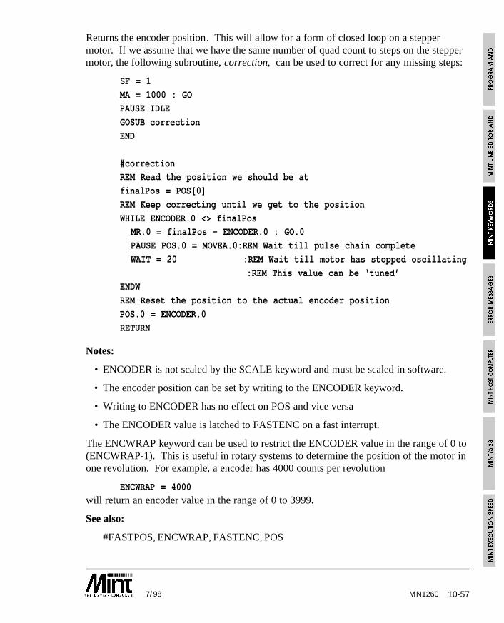
10-577/98
Returns the encoder position. This will allow for a form of closed loop on a steppermotor. If we assume that we have the same number of quad count to steps on the steppermotor, the following subroutine, correction, can be used to correct for any missing steps:
SF = 1
MA = 1000 : GOPAUSE IDLE
GOSUB correction
END
#correctionREM Read the position we should be at
finalPos = POS[0]
REM Keep correcting until we get to the position
WHILE ENCODER.0 <> finalPosMR.0 = finalPos - ENCODER.0 : GO.0
PAUSE POS.0 = MOVEA.0:REM Wait till pulse chain complete
WAIT = 20 :REM Wait till motor has stopped oscillating
:REM This value can be ‘tuned’ENDW
REM Reset the position to the actual encoder position
POS.0 = ENCODER.0
RETURN
Notes:
• ENCODER is not scaled by the SCALE keyword and must be scaled in software.
• The encoder position can be set by writing to the ENCODER keyword.
• Writing to ENCODER has no effect on POS and vice versa
• The ENCODER value is latched to FASTENC on a fast interrupt.
The ENCWRAP keyword can be used to restrict the ENCODER value in the range of 0 to(ENCWRAP-1). This is useful in rotary systems to determine the position of the motor inone revolution. For example, a encoder has 4000 counts per revolution
ENCWRAP = 4000will return an encoder value in the range of 0 to 3999.
See also:
#FASTPOS, ENCWRAP, FASTENC, POS
MN1260
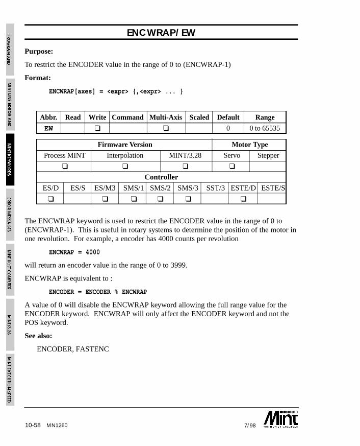
10-58 7/98MN1260
ENCWRAP/EW
Purpose:
To restrict the ENCODER value in the range of 0 to (ENCWRAP-1)
Format:
ENCWRAP[axes] = <expr> {,<expr> ... }
Abbr. Read Write Command Multi-Axis Scaled Default Range
EW ❑ ❑ 0 0 to 65535
Firmware Version Motor Type
Process MINT Interpolation MINT/3.28 Servo Stepper
❑ ❑ ❑ ❑
Controller
ES/D ES/S ES/M3 SMS/1 SMS/2 SMS/3 SST/3 ESTE/D ESTE/S
❑ ❑ ❑ ❑ ❑ ❑
The ENCWRAP keyword is used to restrict the ENCODER value in the range of 0 to(ENCWRAP-1). This is useful in rotary systems to determine the position of the motor inone revolution. For example, a encoder has 4000 counts per revolution
ENCWRAP = 4000
will return an encoder value in the range of 0 to 3999.
ENCWRAP is equivalent to :
ENCODER = ENCODER % ENCWRAP
A value of 0 will disable the ENCWRAP keyword allowing the full range value for theENCODER keyword. ENCWRAP will only affect the ENCODER keyword and not thePOS keyword.
See also:
ENCODER, FASTENC
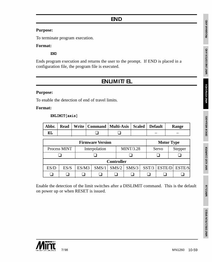
10-597/98 MN1260
END
Purpose:
To terminate program execution.
Format:
END
Ends program execution and returns the user to the prompt. If END is placed in aconfiguration file, the program file is executed.
ENLIMIT/EL
Purpose:
To enable the detection of end of travel limits.
Format:
ENLIMIT[axis]
Abbr. Read Write Command Multi-Axis Scaled Default Range
EL ❑ ❑ – –
Firmware Version Motor Type
Process MINT Interpolation MINT/3.28 Servo Stepper
❑ ❑ ❑ ❑ ❑
Controller
ES/D ES/S ES/M3 SMS/1 SMS/2 SMS/3 SST/3 ESTE/D ESTE/S
❑ ❑ ❑ ❑ ❑ ❑ ❑ ❑ ❑
Enable the detection of the limit switches after a DISLIMIT command. This is the defaulton power up or when RESET is issued.

10-60 7/98
Example:
#ONERROR
DISLIMIT[0,1] : REM Disable limitsSERVOFF[0,1] : REM Allow manual movement of axis
PAUSE !LIMIT[0,1] : REM Wait to move off limits
SERVOC[0,1] : REM Servo power on
ENLIMIT[0,1] : REM Re-enable the limits
RETURN : REM and resume execution
ENLIMIT is different from DISLIMIT in that it does not force a CANCEL.
See also:
DISLIMIT, LIMIT, RESET
ERR
Purpose:
To read the MINT error which resulted in the calling of ONERROR.
Format:
v = ERR
When ONERROR is called, ERR is set with an error number. This can be used in theONERROR routine to determine the error. ERR should be used on conjunction withERROR to determine the axis error.
Error handling is explained in more detail in section 8.
See Also:
ERROR, ERRAXIS
MN1260
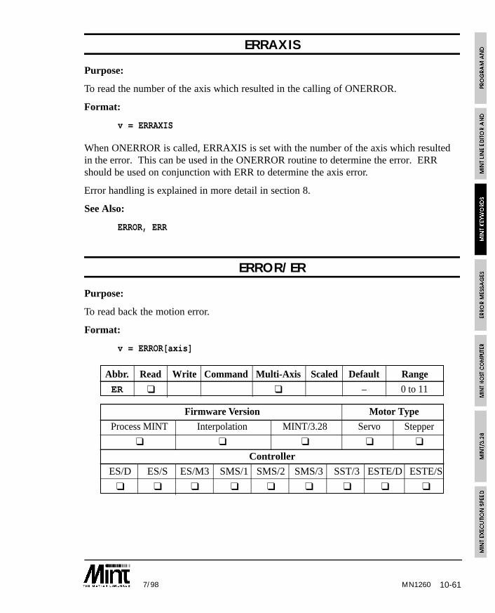
10-617/98 MN1260
ERRAXIS
Purpose:
To read the number of the axis which resulted in the calling of ONERROR.
Format:
v = ERRAXIS
When ONERROR is called, ERRAXIS is set with the number of the axis which resultedin the error. This can be used in the ONERROR routine to determine the error. ERRshould be used on conjunction with ERR to determine the axis error.
Error handling is explained in more detail in section 8.
See Also:
ERROR, ERR
ERROR/ER
Purpose:
To read back the motion error.
Format:
v = ERROR[axis]
Abbr. Read Write Command Multi-Axis Scaled Default Range
ER ❑ ❑ – 0 to 11
Firmware Version Motor Type
Process MINT Interpolation MINT/3.28 Servo Stepper
❑ ❑ ❑ ❑ ❑
Controller
ES/D ES/S ES/M3 SMS/1 SMS/2 SMS/3 SST/3 ESTE/D ESTE/S
❑ ❑ ❑ ❑ ❑ ❑ ❑ ❑ ❑
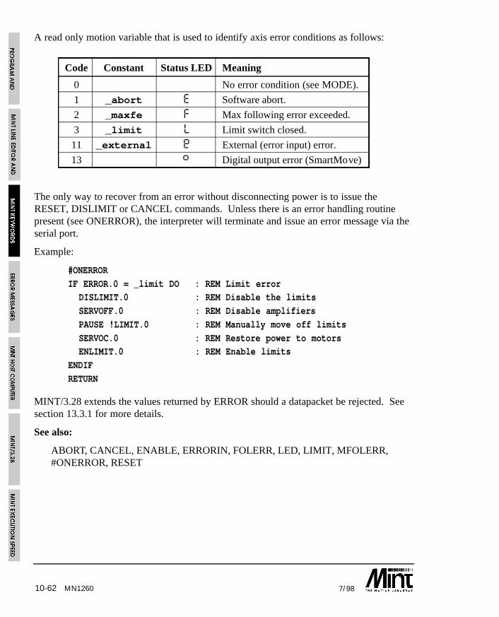
10-62 7/98MN1260
A read only motion variable that is used to identify axis error conditions as follows:
Code Constant Status LED Meaning
0 No error condition (see MODE).
1 _abort E Software abort.
2 _maxfe F Max following error exceeded.
3 _limit L Limit switch closed.
11 _external Ø External (error input) error.
13 ß Digital output error (SmartMove)
The only way to recover from an error without disconnecting power is to issue theRESET, DISLIMIT or CANCEL commands. Unless there is an error handling routinepresent (see ONERROR), the interpreter will terminate and issue an error message via theserial port.
Example:
#ONERROR
IF ERROR.0 = _limit DO : REM Limit errorDISLIMIT.0 : REM Disable the limits
SERVOFF.0 : REM Disable amplifiers
PAUSE !LIMIT.0 : REM Manually move off limits
SERVOC.0 : REM Restore power to motorsENLIMIT.0 : REM Enable limits
ENDIF
RETURN
MINT/3.28 extends the values returned by ERROR should a datapacket be rejected. Seesection 13.3.1 for more details.
See also:
ABORT, CANCEL, ENABLE, ERRORIN, FOLERR, LED, LIMIT, MFOLERR,#ONERROR, RESET

10-637/98 MN1260
ERRORIN/EI
Purpose:
To set the active state of the external error input or read the current state of the input.
Format:
ERRORIN = <expr>
Abbr. Read Write Command Multi-Axis Scaled Default Range
EI ❑ ❑ 2 0 to 2
Firmware Version Motor Type
Process MINT Interpolation MINT/3.28 Servo Stepper
❑ ❑ ❑ ❑ ❑
Controller
ES/D ES/S ES/M3 SMS/1 SMS/2 SMS/3 SST/3 ESTE/D ESTE/S
❑ ❑ ❑ ❑ ❑ ❑ ❑ ❑ ❑
Determines the state of the error input (external error). ERRORIN accepts one of thefollowing values:
Value Function
0 Error input active low.
1 Error input active high
2 Error input disabled
ERRORIN will default to 2 on power up and should be changed to suit your system.
Example:
ERRORIN = 0will set the error input to active low. If an ONERROR subroutine is defined, this will becalled when the error input is grounded (connect to power if PNP inputs are used).
Reading ERRORIN will return the state of the error input.
See also:
ERROR, #ONERROR
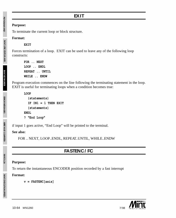
10-64 7/98
EXIT
Purpose:
To terminate the current loop or block structure.
Format:
EXIT
Forces termination of a loop. EXIT can be used to leave any of the following loopconstructs:
FOR .. NEXTLOOP .. ENDL
REPEAT .. UNTIL
WHILE .. ENDW
Program execution commences on the line following the terminating statement in the loop.EXIT is useful for terminating loops when a condition becomes true:
LOOP{statements}
IF IN1 = 1 THEN EXIT
{statements}
ENDL
? “End Loop”
if input 1 goes active, “End Loop” will be printed to the terminal.
See also:
FOR .. NEXT, LOOP..ENDL, REPEAT..UNTIL, WHILE..ENDW
FASTENC/FC
Purpose:
To return the instantaneous ENCODER position recorded by a fast interrupt
Format:
v = FASTENC[axis]
MN1260

10-657/98 MN1260
Abbr. Read Write Command Multi-Axis Scaled Default Range
FC ❑ ❑ – –
Firmware Version Motor Type
Process MINT Interpolation MINT/3.28 Servo Stepper
❑ ❑ ❑ ❑
Controller
ES/D ES/S ES/M3 SMS/1 SMS/2 SMS/3 SMM/1 SMM/2 SMM/3 SST/3 ESTE/D ESTE/S
❑ ❑ ❑ ❑ ❑ ❑ ❑ ❑ ❑
The ENCODER position is latched to the FASTENC keyword on the fast interrupt. Thisoperates in the same way as FASTPOS. If an ENCWRAP value is defined, the FASTENCvalue will be returned within the range of 0 to (ENCWRAP - 1).
Example:
#FASTPOS
IF MODE = _follow THEN OFFSET = FASTENC - 1000
RETURN
See also:
#FASTPOS, ENCODER, ENCWRAP, FASTPOS
FASTPOS/FP
Purpose:
To return the instantaneous position that was recorded on the fast interrupt.
Format:
v = FASTPOS[axis]
Abbr. Read Write Command Multi-Axis Scaled Default Range
FP ❑ ❑ ❑ – –
Firmware Version Motor Type
Process MINT Interpolation MINT/3.28 Servo Stepper
❑ ❑ ❑ ❑ ❑
Controller
ES/D ES/S ES/M3 SMS/1 SMS/2 SMS/3 SST/3 ESTE/D ESTE/S
❑ ❑ ❑ ❑ ❑ ❑ ❑ ❑ ❑
10-66 7/98
When the controller receives a fast interrupt, the axis position is read and stored in theFASTPOS keyword. Unlike the POS keyword which is updated every loop closure (1 or 2milli-seconds), the FASTPOS position is the axis position read at the time of the fastinterrupt. The maximum latency to read the fast position is in the order of 30 micro-seconds.
If the #FASTPOS subroutine is defined, this will be called in response to the fast interrupt.Unlike the MINT interrupts which require a minimum pulse width of 2ms, the fastinterrupt will be latched on a pulse width of about 30 micro-seconds, although a width of100 micro-seconds is recommended. The fast interrupt is level dependent, the positionbeing latched when the fast interrupt is high.
Due to the speed of the fast interrupt, it may be necessary to de-couple the input to avoidspurious calls to the #FASTPOS routine.
The value returned by the FASTPOS keyword is dependent on the scale factor.
Example:
#FASTPOSREM Measure distance between 2 consecutive fast interrupts
IF FASTPOS.1 - lastFastPos > labelLength/2 DO
measured = FASTPOS.1 - lastFastPos
lastFastPos = FASTPOS.1ENDIF
RETURN
In a mixed servo/stepper system, only the servo axes will be latched by the fast interrupt.
See also:
#FASTPOS, ENCODER, FASTENC, POS
FLY/FY
Purpose:
To create a flying shear by locking the slave position to master position with controlledacceleration and deceleration.
Format:
FLY[axes] = <expr> {,<expr>}
MN1260
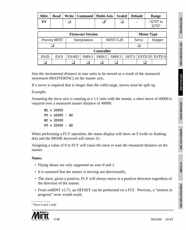
10-677/98 MN1260
17Axes 0 and 1 only
Abbr. Read Write Command Multi-Axis Scaled Default Range
FY ❑ ❑17 ❑ – -32767 to32767
Firmware Version Motor Type
Process MINT Interpolation MINT/3.28 Servo Stepper
❑ ❑
Controller
ES/D ES/S ES/M3 SMS/1 SMS/2 SMS/3 SST/3 ESTE/D ESTE/S
❑ ❑ ❑ ❑ ❑ ❑
Sets the incremental distance in user units to be moved as a result of the measuredmovement (MASTERINC) on the master axis.
If a move is required that is longer than the valid range, moves must be split up.
Example:
Assuming the slave axis is running at a 1:1 ratio with the master, a slave move of 40000 isrequired over a measured master distance of 40000:
MI = 20000FY = 20000 : GO
MI = 20000
FY = 20000 : GO
When performing a FLY operation, the status display will show an F (with no flashingdot) and the MODE keyword will return 15.
Assigning a value of 0 to FLY will cause the slave to wait the measured distance on themaster.
Notes:
• Flying shears are only supported on axes 0 and 1.
• It is assumed that the master is moving uni-directionally.
• The slave, given a positive, FLY will always move in a positive direction regardless ofthe direction of the master.
• From esMINT v2.71, an OFFSET can be performed on a FLY. Previous, a “motion inprogress” error would result.
10-68 7/98MN1260
• FLY moves are buffered in the same was as position moves. To set an output, forexample, when the slave has reached its desired position, the OUT statement must beplaced after the buffered move as shown:
MI = 1000
FY = 500 : GOFY = 1000 : GO
OUT0 = 1 : REM Set output when FY = 500 has finished
See section 6.8 for details on flying shears.
See also:
CAM. CAMA, FOLLOW, FOLLOWAXIS, GEARN, GEARD, GO, MASTERINC,TRIGGER
FOLERR/FE
Purpose:
To return the instantaneous following error value.
Format:
v = FOLERR[axis]
Abbr. Read Write Command Multi-Axis Scaled Default Range
FE ❑ ❑ ❑ – -32767 to32767
Firmware Version Motor Type
Process MINT Interpolation MINT/3.28 Servo Stepper
❑ ❑ ❑ ❑ ❑
Controller
ES/D ES/S ES/M3 SMS/1 SMS/2 SMS/3 SST/3 ESTE/D ESTE/S
❑ ❑ ❑ ❑ ❑ ❑
10-697/98
Returns instantaneous following error where the following error is defined as the demandposition (where you want to be) minus the actual motor position. If the following errorexceeds the value set by MFOLERR (maximum following error) an error is generatedwhich is shown by an ‘F’ on the LCD display and the ERROR keyword will be set to 2. Ifan ONERROR routine is defined, this will be called otherwise program execution will beaborted with the error message:
ERROR: Program: Following error on axis Y at line XXX
Reading the following error during a move is useful for tuning the system. For example:
MOVEA = 100 : GO.0
WHILE !IDLE.0? FE.0
ENDW
? FE.0
will print the following error continuously to the terminal while the move is in progress.
Note that the value returned is dependent on the scale factor, SCALE. For systemcommissioning, the following error can be written to a DAC output using the AUXkeyword. This allows you to view the following error using an oscilloscope.
Velocity feedforward (KVELFF) can be used to reduce the dynamic following error.KINT can be used to reduce the static following error.
See also:
AUX, ERROR, MFOLERR, POS, SCALE
FOLLOW/FL
Purpose:
To enable encoder following with a specified gear ratio.
Format:
FOLLOW[axes] = <expression> {,<expression> ...}
v = FOLLOW[axis]
MN1260
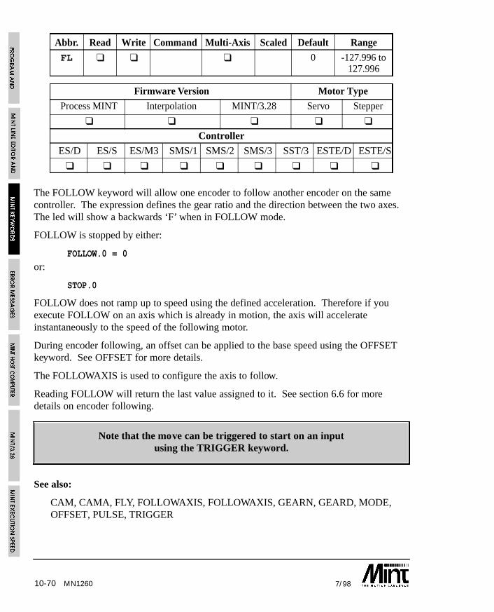
10-70 7/98MN1260
Abbr. Read Write Command Multi-Axis Scaled Default Range
FL ❑ ❑ ❑ 0 -127.996 to127.996
Firmware Version Motor Type
Process MINT Interpolation MINT/3.28 Servo Stepper
❑ ❑ ❑ ❑ ❑
Controller
ES/D ES/S ES/M3 SMS/1 SMS/2 SMS/3 SST/3 ESTE/D ESTE/S
❑ ❑ ❑ ❑ ❑ ❑ ❑ ❑ ❑
The FOLLOW keyword will allow one encoder to follow another encoder on the samecontroller. The expression defines the gear ratio and the direction between the two axes.The led will show a backwards ‘F’ when in FOLLOW mode.
FOLLOW is stopped by either:
FOLLOW.0 = 0
or:
STOP.0
FOLLOW does not ramp up to speed using the defined acceleration. Therefore if youexecute FOLLOW on an axis which is already in motion, the axis will accelerateinstantaneously to the speed of the following motor.
During encoder following, an offset can be applied to the base speed using the OFFSETkeyword. See OFFSET for more details.
The FOLLOWAXIS is used to configure the axis to follow.
Reading FOLLOW will return the last value assigned to it. See section 6.6 for moredetails on encoder following.
Note that the move can be triggered to start on an inputusing the TRIGGER keyword.
See also:
CAM, CAMA, FLY, FOLLOWAXIS, FOLLOWAXIS, GEARN, GEARD, MODE,OFFSET, PULSE, TRIGGER
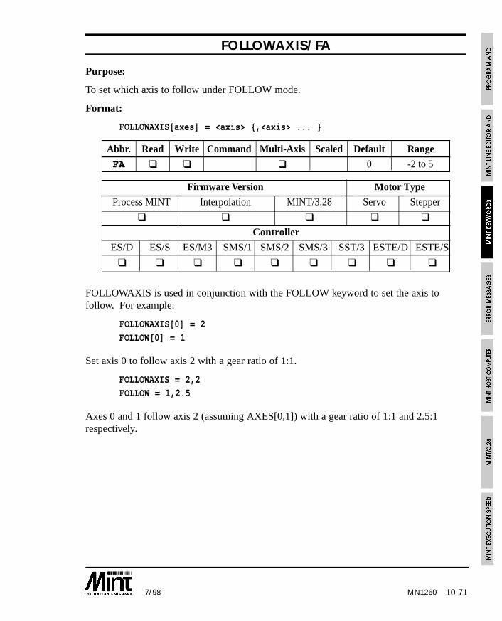
10-717/98 MN1260
FOLLOWAXIS/FA
Purpose:
To set which axis to follow under FOLLOW mode.
Format:
FOLLOWAXIS[axes] = <axis> {,<axis> ... }
Abbr. Read Write Command Multi-Axis Scaled Default Range
FA ❑ ❑ ❑ 0 -2 to 5
Firmware Version Motor Type
Process MINT Interpolation MINT/3.28 Servo Stepper
❑ ❑ ❑ ❑ ❑
Controller
ES/D ES/S ES/M3 SMS/1 SMS/2 SMS/3 SST/3 ESTE/D ESTE/S
❑ ❑ ❑ ❑ ❑ ❑ ❑ ❑ ❑
FOLLOWAXIS is used in conjunction with the FOLLOW keyword to set the axis tofollow. For example:
FOLLOWAXIS[0] = 2
FOLLOW[0] = 1
Set axis 0 to follow axis 2 with a gear ratio of 1:1.
FOLLOWAXIS = 2,2FOLLOW = 1,2.5
Axes 0 and 1 follow axis 2 (assuming AXES[0,1]) with a gear ratio of 1:1 and 2.5:1respectively.
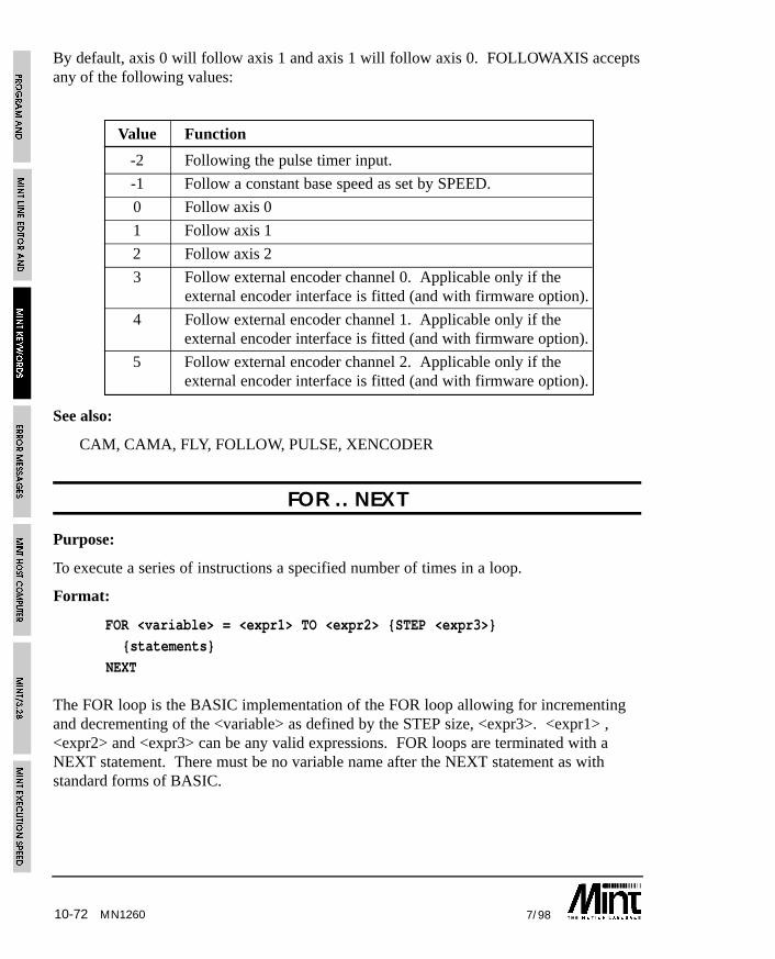
10-72 7/98MN1260
By default, axis 0 will follow axis 1 and axis 1 will follow axis 0. FOLLOWAXIS acceptsany of the following values:
Value Function
-2 Following the pulse timer input.
-1 Follow a constant base speed as set by SPEED.
0 Follow axis 0
1 Follow axis 1
2 Follow axis 2
3 Follow external encoder channel 0. Applicable only if theexternal encoder interface is fitted (and with firmware option).
4 Follow external encoder channel 1. Applicable only if theexternal encoder interface is fitted (and with firmware option).
5 Follow external encoder channel 2. Applicable only if theexternal encoder interface is fitted (and with firmware option).
See also:
CAM, CAMA, FLY, FOLLOW, PULSE, XENCODER
FOR .. NEXT
Purpose:
To execute a series of instructions a specified number of times in a loop.
Format:
FOR <variable> = <expr1> TO <expr2> {STEP <expr3>}
{statements}
NEXT
The FOR loop is the BASIC implementation of the FOR loop allowing for incrementingand decrementing of the <variable> as defined by the STEP size, <expr3>. <expr1> ,<expr2> and <expr3> can be any valid expressions. FOR loops are terminated with aNEXT statement. There must be no variable name after the NEXT statement as withstandard forms of BASIC.

10-737/98
Example:
FOR a = 1 TO 10 : REM Perform loop 10 times
REM Move to the XY position in the arrayMOVEA = xpos(a), ypos(a) : GO
PAUSE IDLE[0,1] : REM Wait for axes to stop
OUT1 = _on : REM Set the output
WAIT = 250 : REM Wait 1/4 second
OUT = _off : REM Turn the output offNEXT
When the loop terminates, the value of the variable will equal the upper limit (expr2). Itwill never exceed it for a positive number.
FOR .. NEXT loops may be nested up to 10 levels as follows:
FOR a = 1 TO 100 STEP 10MOVEA[0] = a : GO
FOR b = 1 to 10
MOVEA[1] = b : GO
NEXTNEXT
A FOR NEXT loop can be terminated prematurely using the EXIT keyword.
See also:
EXIT, LOOP..ENDL, REPEAT..UNTIL, WHILE..ENDW
FREQ/FQ
Purpose:
To set a constant frequency output.
Format:
FREQ[axes] = <expression> {,<expression> ...}v = FREQ[axis]
MN1260
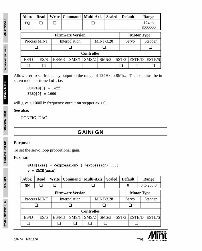
10-74 7/98MN1260
Abbr. Read Write Command Multi-Axis Scaled Default Range
FQ ❑ ❑ ❑ – 124 to8000000
Firmware Version Motor Type
Process MINT Interpolation MINT/3.28 Servo Stepper
❑ ❑ ❑ ❑
Controller
ES/D ES/S ES/M3 SMS/1 SMS/2 SMS/3 SST/3 ESTE/D ESTE/S
❑ ❑ ❑ ❑ ❑
Allow user to set frequency output in the range of 124Hz to 8Mhz. The axis must be inservo mode or turned off. i.e.
CONFIG[0] = _off
FREQ[0] = 1000
will give a 1000Hz frequency output on stepper axis 0.
See also:
CONFIG, DAC
GAIN/GN
Purpose:
To set the servo loop proportional gain.
Format:
GAIN[axes] = <expression> {,<expression> ...}v = GAIN[axis]
Abbr. Read Write Command Multi-Axis Scaled Default Range
GN ❑ ❑ ❑ 0 0 to 255.0
Firmware Version Motor Type
Process MINT Interpolation MINT/3.28 Servo Stepper
❑ ❑ ❑ ❑
Controller
ES/D ES/S ES/M3 SMS/1 SMS/2 SMS/3 SST/3 ESTE/D ESTE/S
❑ ❑ ❑ ❑ ❑ ❑
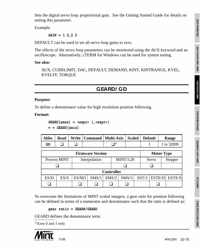
10-757/98 MN1260
18Axes 0 and 1 only
Sets the digital servo loop proportional gain. See the Getting Started Guide for details onsetting this parameter.
Example:
GAIN = 1.5,2.5
DEFAULT can be used to set all servo loop gains to zero.
The effects of the servo loop parameters can be monitored using the AUX keyword and anoscilloscope. Alternatively, cTERM for Windows can be used for system tuning.
See also:
AUX, CURRLIMIT, DAC, DEFAULT, DEMAND, KINT, KINTRANGE, KVEL,KVELFF, TORQUE
GEARD/GD
Purpose:
To define a denominator value for high resolution position following.
Format:
GEARD[axes] = <expr> {,<expr>}
v = GEARD[axis]
Abbr. Read Write Command Multi-Axis Scaled Default Range
GD ❑ ❑ ❑18 1 1 to 32000
Firmware Version Motor Type
Process MINT Interpolation MINT/3.28 Servo Stepper
❑ ❑ ❑
Controller
ES/D ES/S ES/M3 SMS/1 SMS/2 SMS/3 SST/3 ESTE/D ESTE/S
❑ ❑ ❑ ❑ ❑ ❑
To overcome the limitations of MINT scaled integers, a gear ratio for position followingcan be defined in terms of a numerator and denominator such that the ratio is defined as:
gear ratio = GEARN/GEARD
GEARD defines the denominator term.
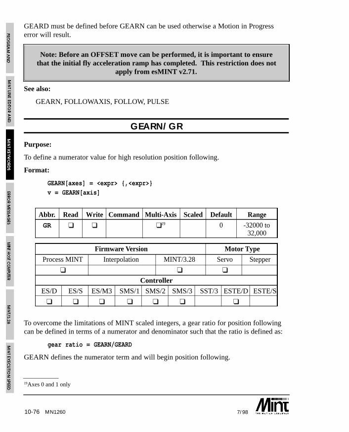
10-76 7/98MN1260
19Axes 0 and 1 only
GEARD must be defined before GEARN can be used otherwise a Motion in Progresserror will result.
Note: Before an OFFSET move can be performed, it is important to ensurethat the initial fly acceleration ramp has completed. This restriction does not
apply from esMINT v2.71.
See also:
GEARN, FOLLOWAXIS, FOLLOW, PULSE
GEARN/GR
Purpose:
To define a numerator value for high resolution position following.
Format:
GEARN[axes] = <expr> {,<expr>}v = GEARN[axis]
Abbr. Read Write Command Multi-Axis Scaled Default Range
GR ❑ ❑ ❑19 0 -32000 to32,000
Firmware Version Motor Type
Process MINT Interpolation MINT/3.28 Servo Stepper
❑ ❑ ❑
Controller
ES/D ES/S ES/M3 SMS/1 SMS/2 SMS/3 SST/3 ESTE/D ESTE/S
❑ ❑ ❑ ❑ ❑ ❑ ❑
To overcome the limitations of MINT scaled integers, a gear ratio for position followingcan be defined in terms of a numerator and denominator such that the ratio is defined as:
gear ratio = GEARN/GEARD
GEARN defines the numerator term and will begin position following.
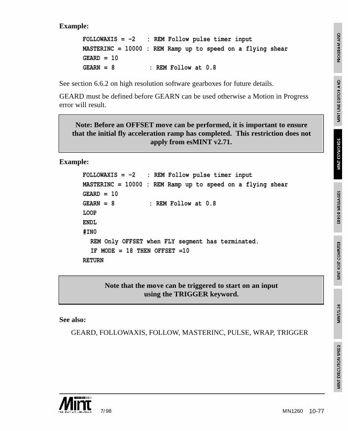
10-777/98
Example:
FOLLOWAXIS = -2 : REM Follow pulse timer input
MASTERINC = 10000 : REM Ramp up to speed on a flying shearGEARD = 10
GEARN = 8 : REM Follow at 0.8
See section 6.6.2 on high resolution software gearboxes for future details.
GEARD must be defined before GEARN can be used otherwise a Motion in Progresserror will result.
Note: Before an OFFSET move can be performed, it is important to ensurethat the initial fly acceleration ramp has completed. This restriction does not
apply from esMINT v2.71.
Example:
FOLLOWAXIS = -2 : REM Follow pulse timer input
MASTERINC = 10000 : REM Ramp up to speed on a flying shear
GEARD = 10
GEARN = 8 : REM Follow at 0.8LOOP
ENDL
#IN0
REM Only OFFSET when FLY segment has terminated. IF MODE = 18 THEN OFFSET =10
RETURN
Note that the move can be triggered to start on an inputusing the TRIGGER keyword.
See also:
GEARD, FOLLOWAXIS, FOLLOW, MASTERINC, PULSE, WRAP, TRIGGER
MN1260
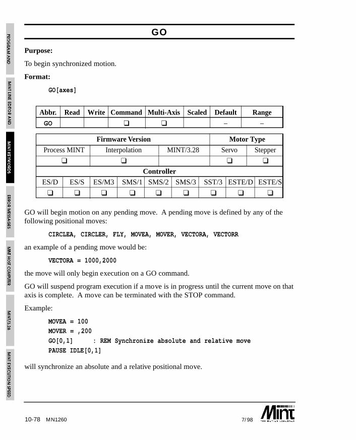
10-78 7/98MN1260
GO
Purpose:
To begin synchronized motion.
Format:
GO[axes]
Abbr. Read Write Command Multi-Axis Scaled Default Range
GO ❑ ❑ – –
Firmware Version Motor Type
Process MINT Interpolation MINT/3.28 Servo Stepper
❑ ❑ ❑ ❑
Controller
ES/D ES/S ES/M3 SMS/1 SMS/2 SMS/3 SST/3 ESTE/D ESTE/S
❑ ❑ ❑ ❑ ❑ ❑ ❑ ❑ ❑
GO will begin motion on any pending move. A pending move is defined by any of thefollowing positional moves:
CIRCLEA, CIRCLER, FLY, MOVEA, MOVER, VECTORA, VECTORR
an example of a pending move would be:
VECTORA = 1000,2000
the move will only begin execution on a GO command.
GO will suspend program execution if a move is in progress until the current move on thataxis is complete. A move can be terminated with the STOP command.
Example:
MOVEA = 100MOVER = ,200
GO[0,1] : REM Synchronize absolute and relative move
PAUSE IDLE[0,1]
will synchronize an absolute and a relative positional move.
10-797/98
GO will take into account the AXES string as in the following example:
AXES[0,1] : REM Default to axis 0 and 1
JOG.1 = 100 : REM Jog axis 1MA = 10 : GO : REM Absolute move on axis 0
will result in a motion in progress error. This can be solved as follows:
AXES[0,1] : REM Default to axis 0 and 1
JOG.1 = 100 : REM Jog axis 1MA = 10 : GO.0 : REM Explicit axis reference on GO
It is possible to synchronize moves off a digital input using the TRIGGER command asshown:
TRIGGER.1 = 1 : REM Trigger off input 1
MOVEA.1 = 100 : GO.1
The axis will move to position 100 when digital input 1 goes from active to inactive.
See section 6.3.6 for more detail on GO.
Note that move commands sent to a MINT/3.28 based controller will executeimmediately without the need for the GO command.
See also:
CIRCLEA, CIRCLER, FLY, IDLE, MODE, MOVEA, MOVECAM, MOVER, STOP,TRIGGER, VECTORA, VECTORR
GOSUB
Purpose:
To branch program execution to a subroutine.
Format:
GOSUB <subroutine_name>
Causes the program to branch to the subroutine with the label given by<subroutine_name>. Since MINT does not support line numbers, all subroutines arereferenced by labels. RETURN is used to resume execution from the statementimmediately following the GOSUB statement.
MN1260
10-80 7/98
Example:
GOSUB init
...END
#init
xpos = 0
ypos = 0fast = 100
slow = 10
RETURN
Notes:
Subroutines can be nested up to 20 levels deep i.e. a subroutine can call anothersubroutine which in turn can call another up to 20 levels.
A maximum of 40* labels can be defined for any given program.
A subroutine defined in the configuration file cannot be called from within theprogram file and vice versa.
GOSUB cannot be used on the command line.
See also:
#, GOTO, #IN0..#IN7, #ONERROR, RETURN, #STOP
MN1260
10-817/98
GOTO
Purpose:
To branch unconditionally out of the normal program sequence to a specified label.
Format:
GOTO label_name
Branches unconditionally to a specified label.
Example:
{ statements }GOTO label1
{statements }
#label1
GOTO should be used with care. Do not use GOTO to jump out of an interrupt routine,loops or block IFs. For example:
LOOP
...
IF IN1 DO
...IF IN2 THEN GOTO abortLoop
...
ENDIF
#abortLoop...
ENDL
will eventually result in a “Stack overflow” error message.
GOTO cannot be used on the command line.
See also:
#, GOSUB
MN1260
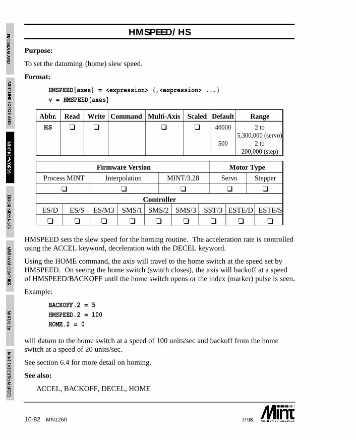
10-82 7/98MN1260
HMSPEED/HS
Purpose:
To set the datuming (home) slew speed.
Format:
HMSPEED[axes] = <expression> {,<expression> ...}
v = HMSPEED[axes]
Abbr. Read Write Command Multi-Axis Scaled Default Range
HS ❑ ❑ ❑ ❑ 40000 2 to 5,300,000 (servo)
500 2 to200,000 (step)
Firmware Version Motor Type
Process MINT Interpolation MINT/3.28 Servo Stepper
❑ ❑ ❑ ❑ ❑
Controller
ES/D ES/S ES/M3 SMS/1 SMS/2 SMS/3 SST/3 ESTE/D ESTE/S
❑ ❑ ❑ ❑ ❑ ❑ ❑ ❑ ❑
HMSPEED sets the slew speed for the homing routine. The acceleration rate is controlledusing the ACCEL keyword, deceleration with the DECEL keyword.
Using the HOME command, the axis will travel to the home switch at the speed set byHMSPEED. On seeing the home switch (switch closes), the axis will backoff at a speedof HMSPEED/BACKOFF until the home switch opens or the index (marker) pulse is seen.
Example:
BACKOFF.2 = 5
HMSPEED.2 = 100HOME.2 = 0
will datum to the home switch at a speed of 100 units/sec and backoff from the homeswitch at a speed of 20 units/sec.
See section 6.4 for more detail on homing.
See also:
ACCEL, BACKOFF, DECEL, HOME
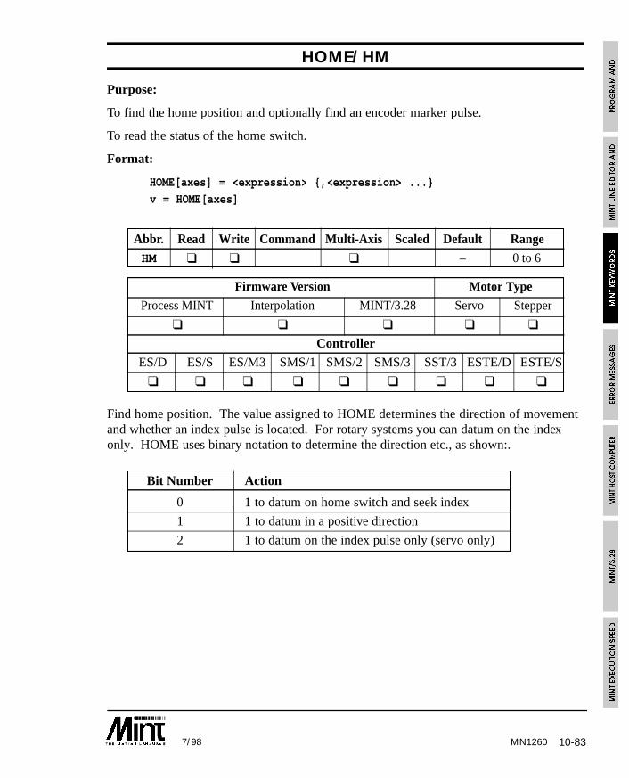
10-837/98 MN1260
HOME/HM
Purpose:
To find the home position and optionally find an encoder marker pulse.
To read the status of the home switch.
Format:
HOME[axes] = <expression> {,<expression> ...}v = HOME[axes]
Abbr. Read Write Command Multi-Axis Scaled Default Range
HM ❑ ❑ ❑ – 0 to 6
Firmware Version Motor Type
Process MINT Interpolation MINT/3.28 Servo Stepper
❑ ❑ ❑ ❑ ❑
Controller
ES/D ES/S ES/M3 SMS/1 SMS/2 SMS/3 SST/3 ESTE/D ESTE/S
❑ ❑ ❑ ❑ ❑ ❑ ❑ ❑ ❑
Find home position. The value assigned to HOME determines the direction of movementand whether an index pulse is located. For rotary systems you can datum on the indexonly. HOME uses binary notation to determine the direction etc., as shown:.
Bit Number Action
0 1 to datum on home switch and seek index
1 1 to datum in a positive direction
2 1 to datum on the index pulse only (servo only)
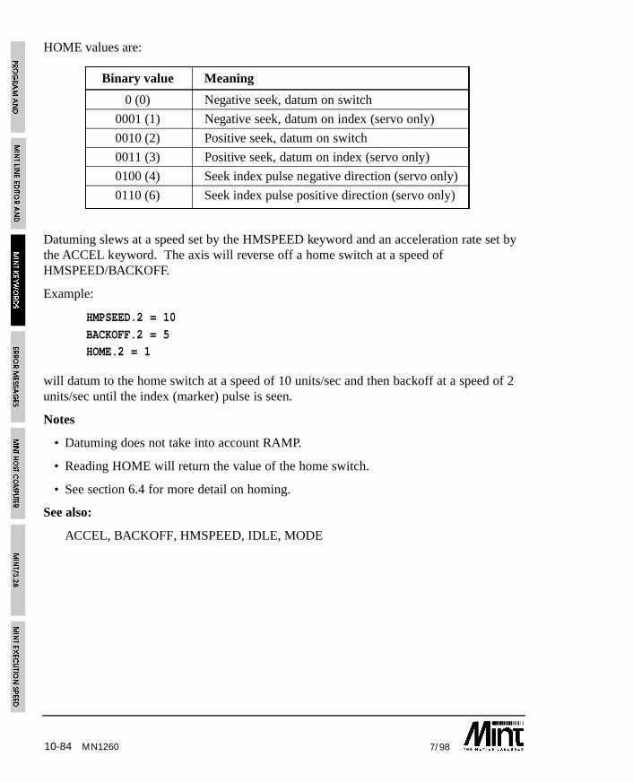
10-84 7/98MN1260
HOME values are:
Binary value Meaning
0 (0) Negative seek, datum on switch
0001 (1) Negative seek, datum on index (servo only)
0010 (2) Positive seek, datum on switch
0011 (3) Positive seek, datum on index (servo only)
0100 (4) Seek index pulse negative direction (servo only)
0110 (6) Seek index pulse positive direction (servo only)
Datuming slews at a speed set by the HMSPEED keyword and an acceleration rate set bythe ACCEL keyword. The axis will reverse off a home switch at a speed ofHMSPEED/BACKOFF.
Example:
HMPSEED.2 = 10
BACKOFF.2 = 5HOME.2 = 1
will datum to the home switch at a speed of 10 units/sec and then backoff at a speed of 2units/sec until the index (marker) pulse is seen.
Notes
• Datuming does not take into account RAMP.
• Reading HOME will return the value of the home switch.
• See section 6.4 for more detail on homing.
See also:
ACCEL, BACKOFF, HMSPEED, IDLE, MODE
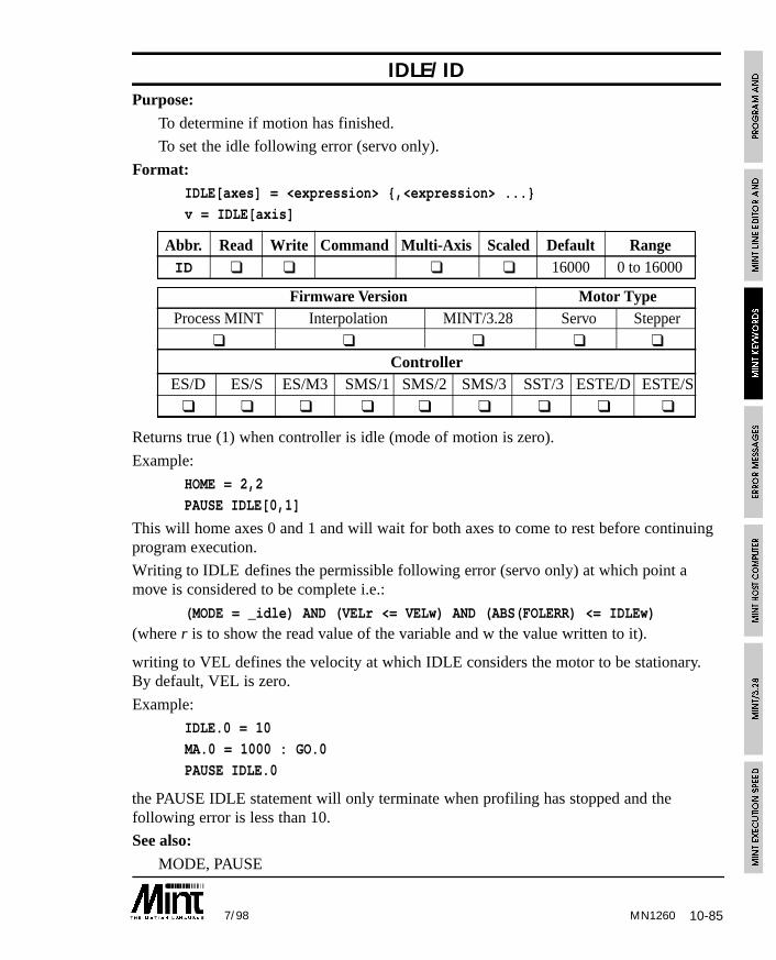
10-857/98 MN1260
IDLE/IDPurpose:
To determine if motion has finished.
To set the idle following error (servo only).
Format: IDLE[axes] = <expression> {,<expression> ...}
v = IDLE[axis]
Abbr. Read Write Command Multi-Axis Scaled Default RangeID ❑ ❑ ❑ ❑ 16000 0 to 16000
Firmware Version Motor TypeProcess MINT Interpolation MINT/3.28 Servo Stepper
❑ ❑ ❑ ❑ ❑
ControllerES/D ES/S ES/M3 SMS/1 SMS/2 SMS/3 SST/3 ESTE/D ESTE/S
❑ ❑ ❑ ❑ ❑ ❑ ❑ ❑ ❑
Returns true (1) when controller is idle (mode of motion is zero).
Example:
HOME = 2,2
PAUSE IDLE[0,1]
This will home axes 0 and 1 and will wait for both axes to come to rest before continuingprogram execution.
Writing to IDLE defines the permissible following error (servo only) at which point amove is considered to be complete i.e.:
(MODE = _idle) AND (VELr <= VELw) AND (ABS(FOLERR) <= IDLEw)(where r is to show the read value of the variable and w the value written to it).
writing to VEL defines the velocity at which IDLE considers the motor to be stationary.By default, VEL is zero.
Example:
IDLE.0 = 10
MA.0 = 1000 : GO.0
PAUSE IDLE.0
the PAUSE IDLE statement will only terminate when profiling has stopped and thefollowing error is less than 10.
See also:
MODE, PAUSE
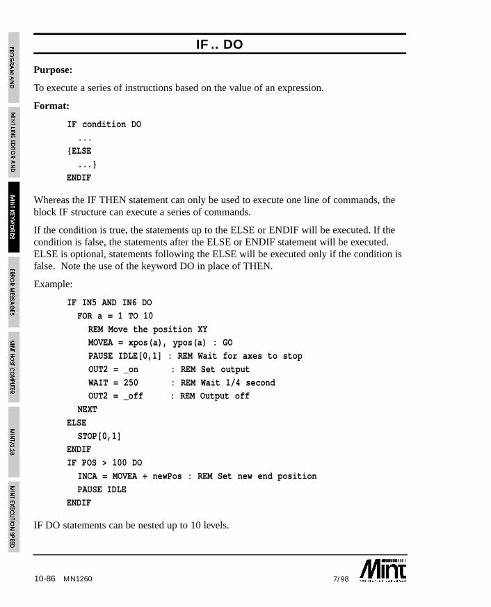
10-86 7/98
IF .. DO
Purpose:
To execute a series of instructions based on the value of an expression.
Format:
IF condition DO
...{ELSE
...}
ENDIF
Whereas the IF THEN statement can only be used to execute one line of commands, theblock IF structure can execute a series of commands.
If the condition is true, the statements up to the ELSE or ENDIF will be executed. If thecondition is false, the statements after the ELSE or ENDIF statement will be executed.ELSE is optional, statements following the ELSE will be executed only if the condition isfalse. Note the use of the keyword DO in place of THEN.
Example:
IF IN5 AND IN6 DO
FOR a = 1 TO 10
REM Move the position XYMOVEA = xpos(a), ypos(a) : GO
PAUSE IDLE[0,1] : REM Wait for axes to stop
OUT2 = _on : REM Set output
WAIT = 250 : REM Wait 1/4 secondOUT2 = _off : REM Output off
NEXT
ELSE
STOP[0,1]ENDIF
IF POS > 100 DO
INCA = MOVEA + newPos : REM Set new end position
PAUSE IDLEENDIF
IF DO statements can be nested up to 10 levels.
MN1260
10-877/98
If the statements can fit onto one line and no ELSE is required,IF .. THEN should be used for program speed.
See also:
IF..THEN
IF .. THEN
Purpose:
To execute a series of instructions based on the value of an expression.
Format:
IF <condition> THEN statements
If the condition is true the statements following THEN and up to the end of the line areexecuted. The condition can be any valid expression (see section 4.6 on relationaloperators).
Examples:
IF POS[0] > 100 AND POS[1] > 200 THEN STOP[0,1]
IF IN2 OR IN3 THEN GOSUB label1
Multiple statements are separated by colons and must be on the same line if they are to beexecuted in the same IF statement.
Example:
IF IN1 THEN OUT1 = 0 : OUT2 = 1
If the statements cannot fit onto one line or an ELSE clause is required,use the IF .. DO structure.
See also:
IF..DO
MN1260
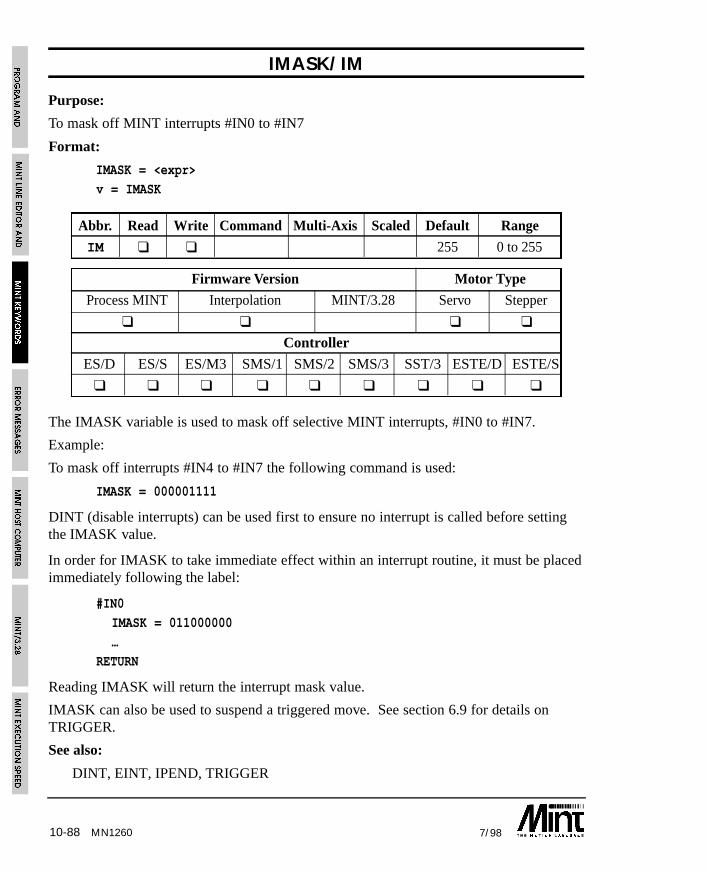
10-88 7/98MN1260
IMASK/IM
Purpose:
To mask off MINT interrupts #IN0 to #IN7
Format:
IMASK = <expr>
v = IMASK
Abbr. Read Write Command Multi-Axis Scaled Default Range
IM ❑ ❑ 255 0 to 255
Firmware Version Motor Type
Process MINT Interpolation MINT/3.28 Servo Stepper
❑ ❑ ❑ ❑
Controller
ES/D ES/S ES/M3 SMS/1 SMS/2 SMS/3 SST/3 ESTE/D ESTE/S
❑ ❑ ❑ ❑ ❑ ❑ ❑ ❑ ❑
The IMASK variable is used to mask off selective MINT interrupts, #IN0 to #IN7.
Example:
To mask off interrupts #IN4 to #IN7 the following command is used:
IMASK = 000001111
DINT (disable interrupts) can be used first to ensure no interrupt is called before settingthe IMASK value.
In order for IMASK to take immediate effect within an interrupt routine, it must be placedimmediately following the label:
#IN0
IMASK = 011000000
…
RETURN
Reading IMASK will return the interrupt mask value.
IMASK can also be used to suspend a triggered move. See section 6.9 for details onTRIGGER.
See also:
DINT, EINT, IPEND, TRIGGER
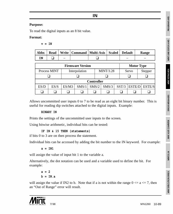
10-897/98 MN1260
IN
Purpose:
To read the digital inputs as an 8 bit value.
Format:
v = IN
Abbr. Read Write Command Multi-Axis Scaled Default Range
IN ❑ – ❑ – –
Firmware Version Motor Type
Process MINT Interpolation MINT/3.28 Servo Stepper
❑ ❑ ❑ ❑ ❑
Controller
ES/D ES/S ES/M3 SMS/1 SMS/2 SMS/3 SST/3 ESTE/D ESTE/S
❑ ❑ ❑ ❑ ❑ ❑ ❑ ❑ ❑
Allows uncommitted user inputs 0 to 7 to be read as an eight bit binary number. This isuseful for reading dip switches attached to the digital inputs. Example:
BINARY IN
Prints the settings of the uncommitted user inputs to the screen.
Using bitwise arithmetic, individual bits can be tested:
IF IN & 15 THEN {statements}
if bits 0 to 3 are on then process the statement.
Individual bits can be accessed by adding the bit number to the IN keyword. For example:
a = IN1
will assign the value of input bit 1 to the variable a.
Alternatively, the dot notation can be used and a variable used to define the bit. Forexample:
a = 2
b = IN.a
will assign the value if IN2 to b. Note that if a is not within the range 0 <= a <= 7, thenan “Out of Range” error will result.
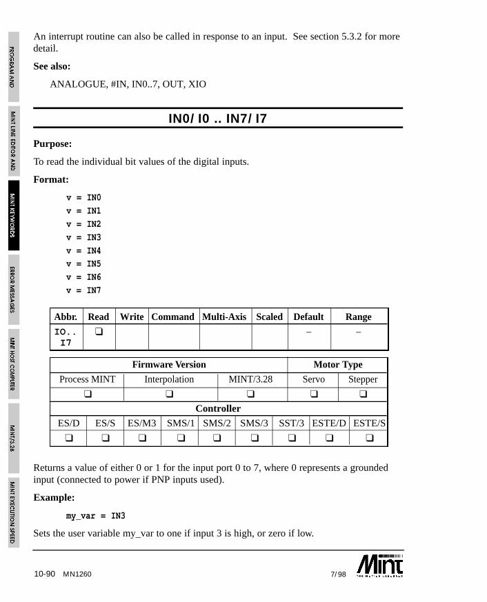
10-90 7/98MN1260
An interrupt routine can also be called in response to an input. See section 5.3.2 for moredetail.
See also:
ANALOGUE, #IN, IN0..7, OUT, XIO
IN0/I0 .. IN7/I7
Purpose:
To read the individual bit values of the digital inputs.
Format:
v = IN0
v = IN1
v = IN2
v = IN3
v = IN4v = IN5
v = IN6
v = IN7
Abbr. Read Write Command Multi-Axis Scaled Default Range
IO.. ❑ – –I7
Firmware Version Motor Type
Process MINT Interpolation MINT/3.28 Servo Stepper
❑ ❑ ❑ ❑ ❑
Controller
ES/D ES/S ES/M3 SMS/1 SMS/2 SMS/3 SST/3 ESTE/D ESTE/S
❑ ❑ ❑ ❑ ❑ ❑ ❑ ❑ ❑
Returns a value of either 0 or 1 for the input port 0 to 7, where 0 represents a groundedinput (connected to power if PNP inputs used).
Example:
my_var = IN3
Sets the user variable my_var to one if input 3 is high, or zero if low.
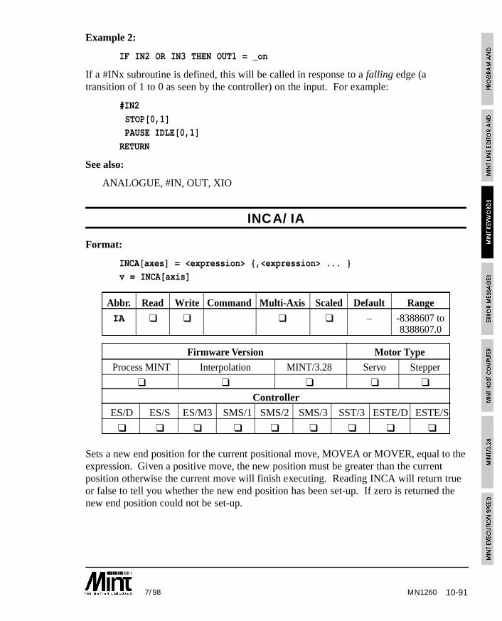
10-917/98 MN1260
Example 2:
IF IN2 OR IN3 THEN OUT1 = _on
If a #INx subroutine is defined, this will be called in response to a falling edge (atransition of 1 to 0 as seen by the controller) on the input. For example:
#IN2
STOP[0,1]PAUSE IDLE[0,1]
RETURN
See also:
ANALOGUE, #IN, OUT, XIO
INCA/IA
Format:
INCA[axes] = <expression> {,<expression> ... }v = INCA[axis]
Abbr. Read Write Command Multi-Axis Scaled Default Range
IA ❑ ❑ ❑ ❑ – -8388607 to8388607.0
Firmware Version Motor Type
Process MINT Interpolation MINT/3.28 Servo Stepper
❑ ❑ ❑ ❑ ❑
Controller
ES/D ES/S ES/M3 SMS/1 SMS/2 SMS/3 SST/3 ESTE/D ESTE/S
❑ ❑ ❑ ❑ ❑ ❑ ❑ ❑ ❑
Sets a new end position for the current positional move, MOVEA or MOVER, equal to theexpression. Given a positive move, the new position must be greater than the currentposition otherwise the current move will finish executing. Reading INCA will return trueor false to tell you whether the new end position has been set-up. If zero is returned thenew end position could not be set-up.
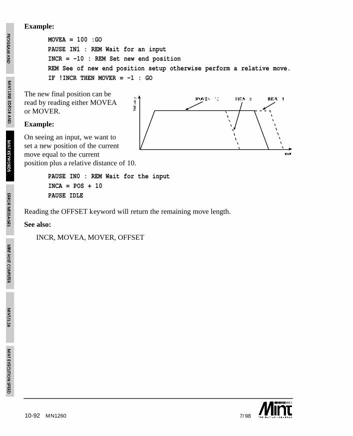
10-92 7/98
Example:
MOVEA = 100 :GO
PAUSE IN1 : REM Wait for an inputINCR = -10 : REM Set new end position
REM See of new end position setup otherwise perform a relative move.
IF !INCR THEN MOVER = -1 : GO
The new final position can beread by reading either MOVEAor MOVER.
Example:
On seeing an input, we want toset a new position of the currentmove equal to the currentposition plus a relative distance of 10.
PAUSE IN0 : REM Wait for the input
INCA = POS + 10
PAUSE IDLE
Reading the OFFSET keyword will return the remaining move length.
See also:
INCR, MOVEA, MOVER, OFFSET
MN1260
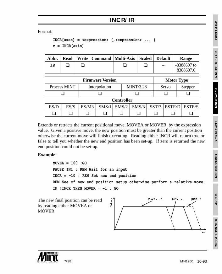
10-937/98 MN1260
INCR/IR
Format:
INCR[axes] = <expression> {,<expression> ... }
v = INCR[axis]
Abbr. Read Write Command Multi-Axis Scaled Default Range
IR ❑ ❑ ❑ ❑ – -8388607 to8388607.0
Firmware Version Motor Type
Process MINT Interpolation MINT/3.28 Servo Stepper
❑ ❑ ❑ ❑ ❑
Controller
ES/D ES/S ES/M3 SMS/1 SMS/2 SMS/3 SST/3 ESTE/D ESTE/S
❑ ❑ ❑ ❑ ❑ ❑ ❑ ❑ ❑
Extends or retracts the current positional move, MOVEA or MOVER, by the expressionvalue. Given a positive move, the new position must be greater than the current positionotherwise the current move will finish executing. Reading either INCR will return true orfalse to tell you whether the new end position has been set-up. If zero is returned the newend position could not be set-up.
Example:
MOVEA = 100 :GO
PAUSE IN1 : REM Wait for an input
INCR = -10 : REM Set new end position
REM See of new end position setup otherwise perform a relative move.
IF !INCR THEN MOVER = -1 : GO
The new final position can be readby reading either MOVEA orMOVER.
10-94 7/98
Example:
In a one axis rolling feed system, a second encoder, on axis 1, is used to detect slip.When the material is near the end of its move, we want to check for slip and correct for it.
PAUSE POS < nearEndPos
INCR = POS.0 - POS.1PAUSE IDLE
Note that axis 1 should be set to servo off mode (SERVOFF) or its axis turned off(CONFIG.1 = _off) to avoid following errors. Reading the OFFSET keyword will returnthe remaining move length.
See also:
INCA, MOVEA, MOVER, OFFSET
INKEY/IK
Purpose:
To read the next key in the serial/keypad buffer.
Format:
v = INKEY
Abbreviation:
IK
INKEY reads a single character from the serial port buffer. IF no character is present itwill return zero, otherwise it returns the ASCII value of the character. (ASCII is aninternational standard defining numeric equivalents to alphanumeric characters).
INKEY always returns the uppercase value of the characters A-Z. Thus:
my_var = INKEY
will return the value 65 (the ASCII value of ‘A’) to the variable my_var if the character ‘A’or ‘a’is present in the buffer.
MN1260
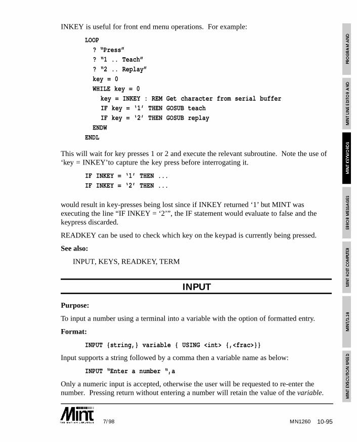
10-957/98
INKEY is useful for front end menu operations. For example:
LOOP
? “Press”? “1 .. Teach”
? “2 .. Replay”
key = 0
WHILE key = 0
key = INKEY : REM Get character from serial bufferIF key = ‘1’ THEN GOSUB teach
IF key = ‘2’ THEN GOSUB replay
ENDW
ENDL
This will wait for key presses 1 or 2 and execute the relevant subroutine. Note the use of‘key = INKEY’to capture the key press before interrogating it.
IF INKEY = ‘1’ THEN ...
IF INKEY = ‘2’ THEN ...
would result in key-presses being lost since if INKEY returned ‘1’ but MINT wasexecuting the line “IF INKEY = ‘2’”, the IF statement would evaluate to false and thekeypress discarded.
READKEY can be used to check which key on the keypad is currently being pressed.
See also:
INPUT, KEYS, READKEY, TERM
INPUT
Purpose:
To input a number using a terminal into a variable with the option of formatted entry.
Format:
INPUT {string,} variable { USING <int> {,<frac>}}
Input supports a string followed by a comma then a variable name as below:
INPUT “Enter a number “,a
Only a numeric input is accepted, otherwise the user will be requested to re-enter thenumber. Pressing return without entering a number will retain the value of the variable.
MN1260
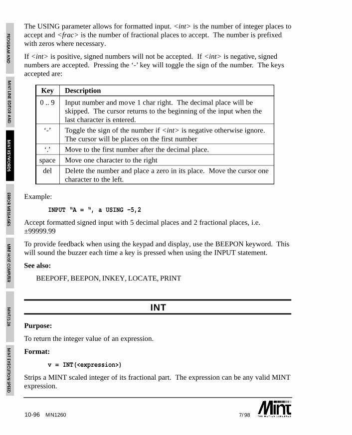
10-96 7/98MN1260
The USING parameter allows for formatted input. <int> is the number of integer places toaccept and <frac> is the number of fractional places to accept. The number is prefixedwith zeros where necessary.
If <int> is positive, signed numbers will not be accepted. If <int> is negative, signednumbers are accepted. Pressing the ‘-’ key will toggle the sign of the number. The keysaccepted are:
Key Description
0 .. 9 Input number and move 1 char right. The decimal place will beskipped. The cursor returns to the beginning of the input when thelast character is entered.
‘-’ Toggle the sign of the number if <int> is negative otherwise ignore.The cursor will be places on the first number
‘.’ Move to the first number after the decimal place.
space Move one character to the right
del Delete the number and place a zero in its place. Move the cursor onecharacter to the left.
Example:
INPUT “A = “, a USING -5,2
Accept formatted signed input with 5 decimal places and 2 fractional places, i.e.±99999.99
To provide feedback when using the keypad and display, use the BEEPON keyword. Thiswill sound the buzzer each time a key is pressed when using the INPUT statement.
See also:
BEEPOFF, BEEPON, INKEY, LOCATE, PRINT
INT
Purpose:
To return the integer value of an expression.
Format:
v = INT(<expression>)
Strips a MINT scaled integer of its fractional part. The expression can be any valid MINTexpression.
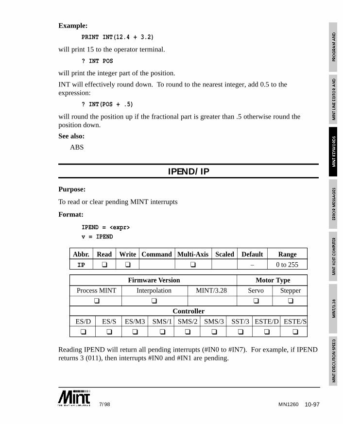
10-977/98 MN1260
Example:
PRINT INT(12.4 + 3.2)
will print 15 to the operator terminal.
? INT POS
will print the integer part of the position.
INT will effectively round down. To round to the nearest integer, add 0.5 to theexpression:
? INT(POS + .5)
will round the position up if the fractional part is greater than .5 otherwise round theposition down.
See also:
ABS
IPEND/IP
Purpose:
To read or clear pending MINT interrupts
Format:
IPEND = <expr>
v = IPEND
Abbr. Read Write Command Multi-Axis Scaled Default Range
IP ❑ ❑ ❑ – 0 to 255
Firmware Version Motor Type
Process MINT Interpolation MINT/3.28 Servo Stepper
❑ ❑ ❑ ❑
Controller
ES/D ES/S ES/M3 SMS/1 SMS/2 SMS/3 SST/3 ESTE/D ESTE/S
❑ ❑ ❑ ❑ ❑ ❑ ❑ ❑ ❑
Reading IPEND will return all pending interrupts (#IN0 to #IN7). For example, if IPENDreturns 3 (011), then interrupts #IN0 and #IN1 are pending.
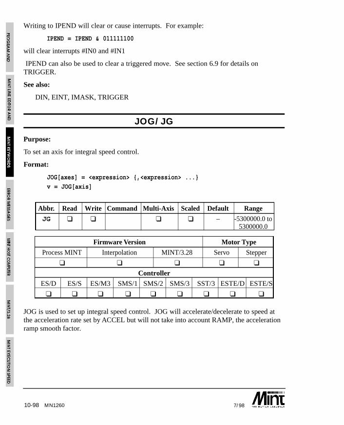
10-98 7/98MN1260
Writing to IPEND will clear or cause interrupts. For example:
IPEND = IPEND & 011111100
will clear interrupts #IN0 and #IN1
IPEND can also be used to clear a triggered move. See section 6.9 for details onTRIGGER.
See also:
DIN, EINT, IMASK, TRIGGER
JOG/JG
Purpose:
To set an axis for integral speed control.
Format:
JOG[axes] = <expression> {,<expression> ...}
v = JOG[axis]
Abbr. Read Write Command Multi-Axis Scaled Default Range
JG ❑ ❑ ❑ ❑ – -5300000.0 to5300000.0
Firmware Version Motor Type
Process MINT Interpolation MINT/3.28 Servo Stepper
❑ ❑ ❑ ❑ ❑
Controller
ES/D ES/S ES/M3 SMS/1 SMS/2 SMS/3 SST/3 ESTE/D ESTE/S
❑ ❑ ❑ ❑ ❑ ❑ ❑ ❑ ❑
JOG is used to set up integral speed control. JOG will accelerate/decelerate to speed atthe acceleration rate set by ACCEL but will not take into account RAMP, the accelerationramp smooth factor.
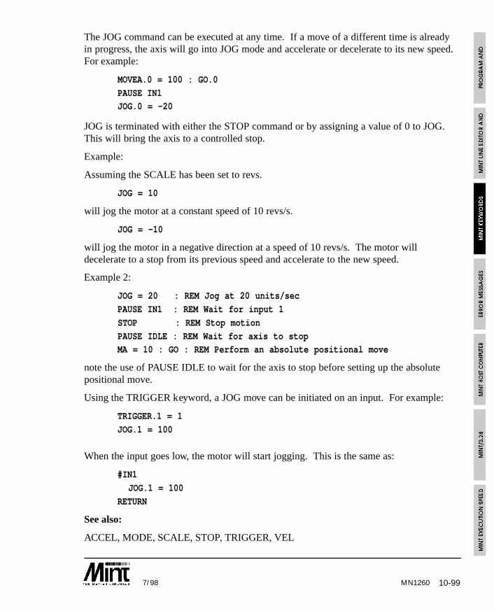
10-997/98
The JOG command can be executed at any time. If a move of a different time is alreadyin progress, the axis will go into JOG mode and accelerate or decelerate to its new speed.For example:
MOVEA.0 = 100 : GO.0
PAUSE IN1JOG.0 = -20
JOG is terminated with either the STOP command or by assigning a value of 0 to JOG.This will bring the axis to a controlled stop.
Example:
Assuming the SCALE has been set to revs.
JOG = 10
will jog the motor at a constant speed of 10 revs/s.
JOG = -10
will jog the motor in a negative direction at a speed of 10 revs/s. The motor willdecelerate to a stop from its previous speed and accelerate to the new speed.
Example 2:
JOG = 20 : REM Jog at 20 units/sec
PAUSE IN1 : REM Wait for input 1
STOP : REM Stop motion
PAUSE IDLE : REM Wait for axis to stopMA = 10 : GO : REM Perform an absolute positional move
note the use of PAUSE IDLE to wait for the axis to stop before setting up the absolutepositional move.
Using the TRIGGER keyword, a JOG move can be initiated on an input. For example:
TRIGGER.1 = 1
JOG.1 = 100
When the input goes low, the motor will start jogging. This is the same as:
#IN1
JOG.1 = 100
RETURN
See also:
ACCEL, MODE, SCALE, STOP, TRIGGER, VEL
MN1260
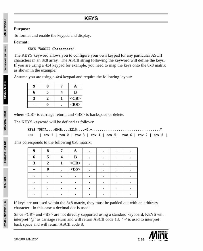
10-100 7/98MN1260
KEYS
Purpose:
To format and enable the keypad and display.
Format:
KEYS “ASCII Characters”
The KEYS keyword allows you to configure your own keypad for any particular ASCIIcharacters in an 8x8 array. The ASCII string following the keyword will define the keys.If you are using a 4x4 keypad for example, you need to map the keys onto the 8x8 matrixas shown in the example:
Assume you are using a 4x4 keypad and require the following layout:
9 8 7 A
6 5 4 B
3 2 1 <CR>
– 0 . <BS>
where <CR> is carriage return, and <BS> is backspace or delete.
The KEYS keyword will be defined as follows:
KEYS “[email protected].~....................................”REM | row 1 | row 2 | row 3 | row 4 | row 5 | row 6 | row 7 | row 8 |
This corresponds to the following 8x8 matrix:
9 8 7 A . . . .
6 5 4 B . . . .
3 2 1 <CR> . . . .
– 0 . <BS> . . . .
. . . . . . . .
. . . . . . . .
. . . . . . . .
. . . . . . . .
If keys are not used within the 8x8 matrix, they must be padded out with an arbitrarycharacter. In this case a decimal dot is used.
Since <CR> and <BS> are not directly supported using a standard keyboard, KEYS willinterpret ‘@’ as carriage return and will return ASCII code 13. ‘~’ is used to interpretback space and will return ASCII code 8.
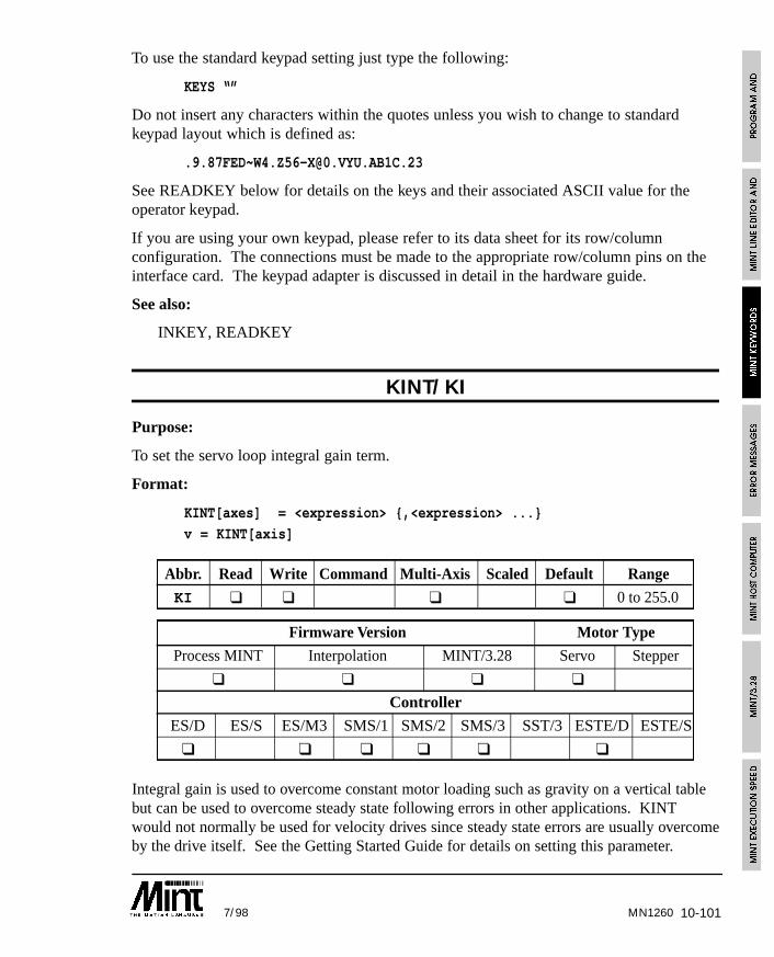
10-1017/98 MN1260
To use the standard keypad setting just type the following:
KEYS “”
Do not insert any characters within the quotes unless you wish to change to standardkeypad layout which is defined as:
See READKEY below for details on the keys and their associated ASCII value for theoperator keypad.
If you are using your own keypad, please refer to its data sheet for its row/columnconfiguration. The connections must be made to the appropriate row/column pins on theinterface card. The keypad adapter is discussed in detail in the hardware guide.
See also:
INKEY, READKEY
KINT/KI
Purpose:
To set the servo loop integral gain term.
Format:
KINT[axes] = <expression> {,<expression> ...}
v = KINT[axis]
Abbr. Read Write Command Multi-Axis Scaled Default Range
KI ❑ ❑ ❑ ❑ 0 to 255.0
Firmware Version Motor Type
Process MINT Interpolation MINT/3.28 Servo Stepper
❑ ❑ ❑ ❑
Controller
ES/D ES/S ES/M3 SMS/1 SMS/2 SMS/3 SST/3 ESTE/D ESTE/S
❑ ❑ ❑ ❑ ❑ ❑
Integral gain is used to overcome constant motor loading such as gravity on a vertical tablebut can be used to overcome steady state following errors in other applications. KINTwould not normally be used for velocity drives since steady state errors are usually overcomeby the drive itself. See the Getting Started Guide for details on setting this parameter.
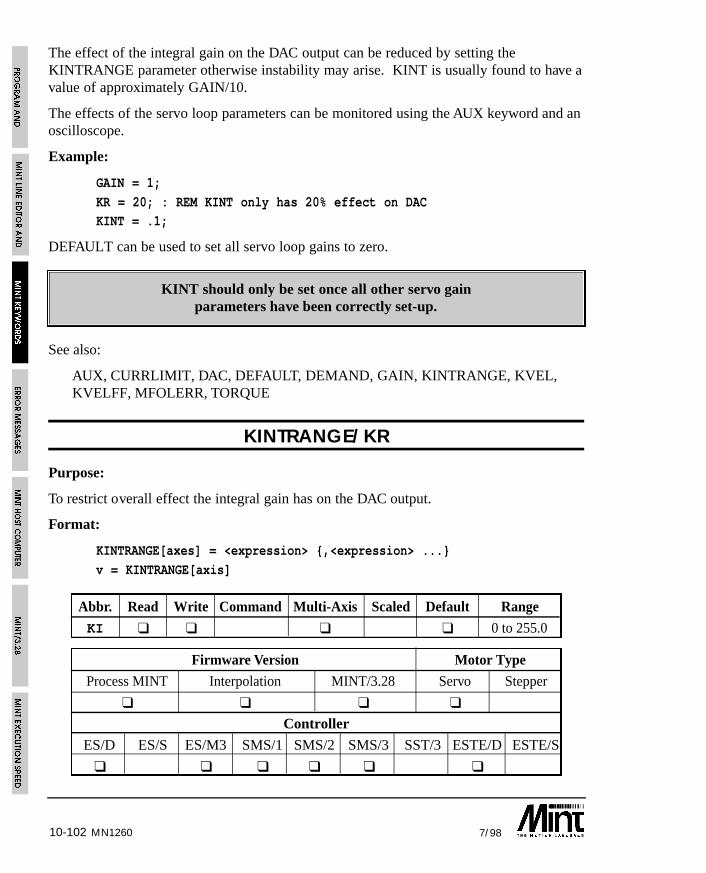
10-102 7/98MN1260
The effect of the integral gain on the DAC output can be reduced by setting theKINTRANGE parameter otherwise instability may arise. KINT is usually found to have avalue of approximately GAIN/10.
The effects of the servo loop parameters can be monitored using the AUX keyword and anoscilloscope.
Example:
GAIN = 1;
KR = 20; : REM KINT only has 20% effect on DACKINT = .1;
DEFAULT can be used to set all servo loop gains to zero.
KINT should only be set once all other servo gainparameters have been correctly set-up.
See also:
AUX, CURRLIMIT, DAC, DEFAULT, DEMAND, GAIN, KINTRANGE, KVEL,KVELFF, MFOLERR, TORQUE
KINTRANGE/KR
Purpose:
To restrict overall effect the integral gain has on the DAC output.
Format:
KINTRANGE[axes] = <expression> {,<expression> ...}
v = KINTRANGE[axis]
Abbr. Read Write Command Multi-Axis Scaled Default Range
KI ❑ ❑ ❑ ❑ 0 to 255.0
Firmware Version Motor Type
Process MINT Interpolation MINT/3.28 Servo Stepper
❑ ❑ ❑ ❑
Controller
ES/D ES/S ES/M3 SMS/1 SMS/2 SMS/3 SST/3 ESTE/D ESTE/S
❑ ❑ ❑ ❑ ❑ ❑
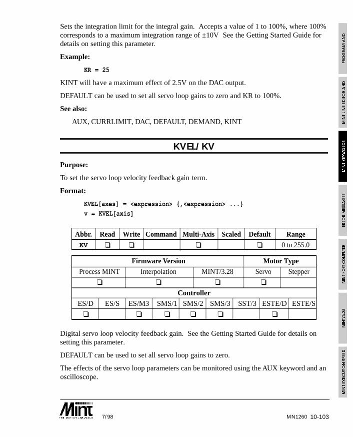
10-1037/98 MN1260
Sets the integration limit for the integral gain. Accepts a value of 1 to 100%, where 100%corresponds to a maximum integration range of ±10V See the Getting Started Guide fordetails on setting this parameter.
Example:
KR = 25
KINT will have a maximum effect of 2.5V on the DAC output.
DEFAULT can be used to set all servo loop gains to zero and KR to 100%.
See also:
AUX, CURRLIMIT, DAC, DEFAULT, DEMAND, KINT
KVEL/KV
Purpose:
To set the servo loop velocity feedback gain term.
Format:
KVEL[axes] = <expression> {,<expression> ...}
v = KVEL[axis]
Abbr. Read Write Command Multi-Axis Scaled Default Range
KV ❑ ❑ ❑ ❑ 0 to 255.0
Firmware Version Motor Type
Process MINT Interpolation MINT/3.28 Servo Stepper
❑ ❑ ❑ ❑
Controller
ES/D ES/S ES/M3 SMS/1 SMS/2 SMS/3 SST/3 ESTE/D ESTE/S
❑ ❑ ❑ ❑ ❑ ❑
Digital servo loop velocity feedback gain. See the Getting Started Guide for details onsetting this parameter.
DEFAULT can be used to set all servo loop gains to zero.
The effects of the servo loop parameters can be monitored using the AUX keyword and anoscilloscope.
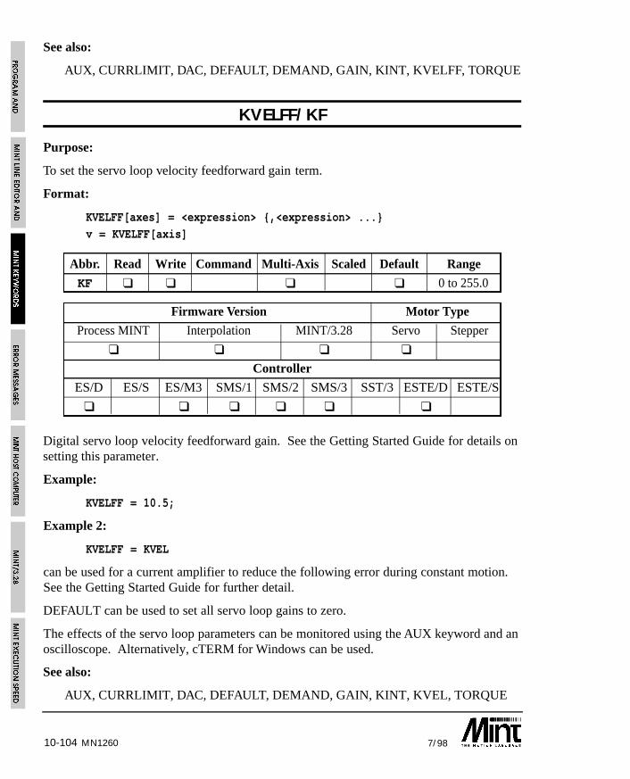
10-104 7/98MN1260
See also:
AUX, CURRLIMIT, DAC, DEFAULT, DEMAND, GAIN, KINT, KVELFF, TORQUE
KVELFF/KF
Purpose:
To set the servo loop velocity feedforward gain term.
Format:
KVELFF[axes] = <expression> {,<expression> ...}v = KVELFF[axis]
Abbr. Read Write Command Multi-Axis Scaled Default Range
KF ❑ ❑ ❑ ❑ 0 to 255.0
Firmware Version Motor Type
Process MINT Interpolation MINT/3.28 Servo Stepper
❑ ❑ ❑ ❑
Controller
ES/D ES/S ES/M3 SMS/1 SMS/2 SMS/3 SST/3 ESTE/D ESTE/S
❑ ❑ ❑ ❑ ❑ ❑
Digital servo loop velocity feedforward gain. See the Getting Started Guide for details onsetting this parameter.
Example:
KVELFF = 10.5;
Example 2:
KVELFF = KVEL
can be used for a current amplifier to reduce the following error during constant motion.See the Getting Started Guide for further detail.
DEFAULT can be used to set all servo loop gains to zero.
The effects of the servo loop parameters can be monitored using the AUX keyword and anoscilloscope. Alternatively, cTERM for Windows can be used.
See also:
AUX, CURRLIMIT, DAC, DEFAULT, DEMAND, GAIN, KINT, KVEL, TORQUE
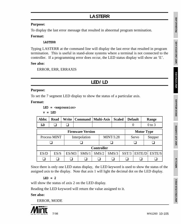
10-1057/98 MN1260
LASTERRPurpose:
To display the last error message that resulted in abnormal program termination.
Format:
LASTERR
Typing LASTERR at the command line will display the last error that resulted in programtermination. This is useful in stand-alone systems where a terminal is not connected to thecontroller. If a programming error does occur, the LED status display will show an ‘E’.
See also:
ERROR, ERR, ERRAXIS
LED/LDPurpose:
To set the 7 segment LED display to show the status of a particular axis.
Format:LED = <expression>
v = LED
Abbr. Read Write Command Multi-Axis Scaled Default Range
LD ❑ ❑ 0 0 to 3
Firmware Version Motor Type
Process MINT Interpolation MINT/3.28 Servo Stepper
❑ ❑ ❑ ❑ ❑
Controller
ES/D ES/S ES/M3 SMS/1 SMS/2 SMS/3 SST/3 ESTE/D ESTE/S
❑ ❑ ❑ ❑ ❑ ❑ ❑ ❑ ❑
Since there is only one LED status display, the LED keyword is used to show the status of theassigned axis to the display. Note that axis 1 will light the decimal dot on the LED display.
LED = 2
will show the status of axis 2 on the LED display.
Reading the LED keyword will return the value assigned to it.
See also:
ERROR, MODE
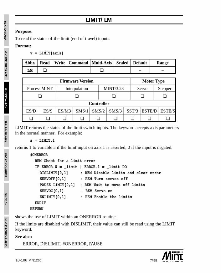
10-106 7/98MN1260
LIMIT/LM
Purpose:
To read the status of the limit (end of travel) inputs.
Format:
v = LIMIT[axis]
Abbr. Read Write Command Multi-Axis Scaled Default Range
LM ❑ ❑ – –
Firmware Version Motor Type
Process MINT Interpolation MINT/3.28 Servo Stepper
❑ ❑ ❑ ❑ ❑
Controller
ES/D ES/S ES/M3 SMS/1 SMS/2 SMS/3 SST/3 ESTE/D ESTE/S
❑ ❑ ❑ ❑ ❑ ❑ ❑ ❑ ❑
LIMIT returns the status of the limit switch inputs. The keyword accepts axis parametersin the normal manner. For example:
a = LIMIT.1
returns 1 to variable a if the limit input on axis 1 is asserted, 0 if the input is negated.
#ONERROR
REM Check for a limit error
IF ERROR.0 = _limit | ERROR.1 = _limit DO
DISLIMIT[0,1] : REM Disable limits and clear errorSERVOFF[0,1] : REM Turn servos off
PAUSE LIMIT[0,1] : REM Wait to move off limits
SERVOC[0,1] : REM Servo on
ENLIMIT[0,1] : REM Enable the limits
ENDIFRETURN
shows the use of LIMIT within an ONERROR routine.
If the limits are disabled with DISLIMIT, their value can still be read using the LIMITkeyword.
See also:
ERROR, DISLIMIT, #ONERROR, PAUSE
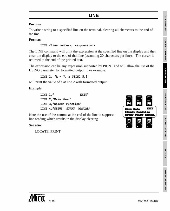
10-1077/98
LINE
Purpose:
To write a string to a specified line on the terminal, clearing all characters to the end ofthe line.
Format:
LINE <line number>, <expression>
The LINE command will print the expression at the specified line on the display and thenclear the display to the end of that line (assuming 20 characters per line). The cursor isreturned to the end of the printed text.
The expression can be any expression supported by PRINT and will allow the use of theUSING parameter for formatted output. For example:
LINE 2, “A = “, a USING 5,2
will print the value of a at line 2 with formatted output.
Example
LINE 1,” EXIT”LINE 2,”Main Menu”
LINE 3,”Select Function”
LINE 4,”SETUP START MANUAL”,
Note the use of the comma at the end of the line to suppressline feeding which results in the display clearing.
See also:
LOCATE, PRINT
MN1260
10-108 7/98MN1260
LOAD
Purpose:
To load a file into the controller using a terminal editor other than cTERM or to load arraydata into an executing program.
Format:
LOAD <buffer>
LOAD can be used to load programs and data into the controller if cTERM is not used.Buffer corresponds to:
Value Buffer
-3 Load array data from memory card if fitted
-2 Load configuration file from memory card if fitted
-1 Load program from memory card if fitted
1 Program buffer, no checksum
2 Configuration buffer, no checksum
3 Array data, no checksum
4 Program buffer with checksum
5 Configuration buffer with checksum
6 Array data with checksum
LOAD can also be used within a program for downloading array data into an executingprogram.
Example:
{ statements }
IF INKEY = ‘L’ THEN GOSUB getData
{ statements }
END#getData
TIME = 0
REPEAT
IF INKEY = ‘3’ THEN : ? “Ok 3”: LOAD 3 : RETURNUNTIL TIME > 1000 : REM TImeout after 1000ms
RETURN

10-1097/98
on receiving an ‘L’, the subroutine getData will be called. If ‘3’ is received the data willbe loaded, otherwise the routine will time-out. This can be used with cTERM which onfile load will send down the string “LOAD” followed by “3” for array data. cTERM willthen expect the response “Ok 3” before downloading the data.
Buffer values 4 to 6 should only be used with cTERM which provides a checksum tocheck for data corruption. Always send “Ok 1” to “Ok 3” in acknowledgement and not“Ok 4” to “Ok 6”.
Data can be loaded to the memory simply using the LOAD command. In order to retrievethe array data from the memory card
LOAD -3
is used.
The upload/download routines as used within cTERM for DOS can be found on theaccompanying diskette. These are written in Turbo C but should be portable among mostC compilers. Alternatively the MINT Interface Library provides functions for Windowsfor many of the popular development suites.
See also:
DIM, DISPLAY, SAVE
LOCATE
Purpose:
To locate the cursor on a VT100 (or VT52) terminal or the LCD display.
Format:
LOCATE <x>,<y>
Using VT100 (or VT52; see TERM) emulation, the cursor is located at column <x>, row<y>, where the top left corner is at location column 1, row 1. <x> and <y> are not rangechecked. The cursor will remain stationary if <x> or <y> are out of bounds of the screenco-ordinates. Example:
LOCATE 10,10 : PRINT “Column 10, Row 10”
The string “Column 10, Row 10” will be printed at column 10, row 10.
<x> and <y> can be any valid MINT expression. If an LCD terminal is connected, thecursor will be located at the given co-ordinates.
See also:
BOL, CLS, INPUT, LINE, PRINT, TERM
MN1260
10-110 7/98
LOOP .. ENDL
Purpose:
To perform an endless loop.
Format:
LOOP{statements}
ENDL
This is the simplest type of loop in MINT, it loops round forever, for instance:
LOOP
JOG = ANALOGUE1/100
ENDL
loops round forever reading analog input one and jogging the motor to a maximum valueof 10.
Notes:
A loop can be terminated by use of the EXIT keyword.
LOOPs can be nested up to 10 levels deep.
See also:
EXIT, FOR..NEXT, REPEAT..UNTIL, WHILE..ENDW
MN1260

10-1117/98 MN1260
LOOPTIME/LT
Purpose:
To set the servo loop time and the number of axes supported.
Format:
LOOPTIME = <expression>
Abbr. Read Write Command Multi-Axis Scaled Default Range
LT ❑ ❑ 2 1 to 2
Firmware Version Motor Type
Process MINT Interpolation MINT/3.28 Servo Stepper
❑ ❑ ❑ ❑
Controller
ES/D ES/S ES/M3 SMS/1 SMS/2 SMS/3 SST/3 ESTE/D ESTE/S
❑ ❑ ❑ ❑ ❑ ❑
Sets the loop closure time and the number of axes supported by MINT. SettingLOOPTIME to 1 will give a loop closure time of 1 ms for one axis of servo control. Thesecond encoder is still accessible using the POS or ENCODER keyword.
LT = 1
A LOOPTIME of 2 will set a loop closure time of 2ms and support 3 axes of motion.
DEFAULT will set LOOPTIME to 2.
See also:
AXES, DEFAULT, TIME
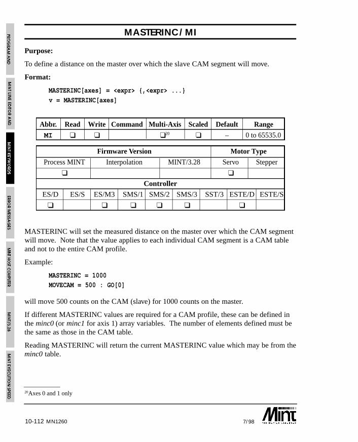
10-112 7/98MN1260
20Axes 0 and 1 only
MASTERINC/MI
Purpose:
To define a distance on the master over which the slave CAM segment will move.
Format:
MASTERINC[axes] = <expr> {,<expr> ...}
v = MASTERINC[axes]
Abbr. Read Write Command Multi-Axis Scaled Default Range
MI ❑ ❑ ❑20 ❑ – 0 to 65535.0
Firmware Version Motor Type
Process MINT Interpolation MINT/3.28 Servo Stepper
❑ ❑
Controller
ES/D ES/S ES/M3 SMS/1 SMS/2 SMS/3 SST/3 ESTE/D ESTE/S
❑ ❑ ❑ ❑ ❑ ❑
MASTERINC will set the measured distance on the master over which the CAM segmentwill move. Note that the value applies to each individual CAM segment is a CAM tableand not to the entire CAM profile.
Example:
MASTERINC = 1000MOVECAM = 500 : GO[0]
will move 500 counts on the CAM (slave) for 1000 counts on the master.
If different MASTERINC values are required for a CAM profile, these can be defined inthe minc0 (or minc1 for axis 1) array variables. The number of elements defined must bethe same as those in the CAM table.
Reading MASTERINC will return the current MASTERINC value which may be from theminc0 table.
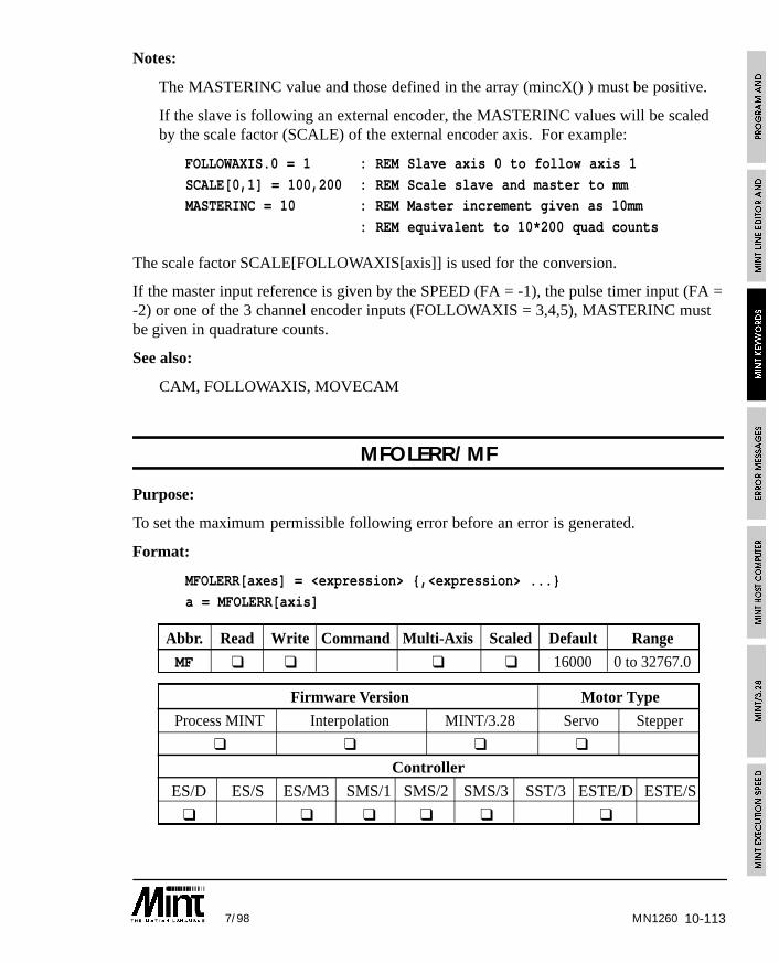
10-1137/98 MN1260
Notes:
The MASTERINC value and those defined in the array (mincX() ) must be positive.
If the slave is following an external encoder, the MASTERINC values will be scaledby the scale factor (SCALE) of the external encoder axis. For example:
FOLLOWAXIS.0 = 1 : REM Slave axis 0 to follow axis 1
SCALE[0,1] = 100,200 : REM Scale slave and master to mmMASTERINC = 10 : REM Master increment given as 10mm
: REM equivalent to 10*200 quad counts
The scale factor SCALE[FOLLOWAXIS[axis]] is used for the conversion.
If the master input reference is given by the SPEED (FA = -1), the pulse timer input (FA =-2) or one of the 3 channel encoder inputs (FOLLOWAXIS = 3,4,5), MASTERINC mustbe given in quadrature counts.
See also:
CAM, FOLLOWAXIS, MOVECAM
MFOLERR/MF
Purpose:
To set the maximum permissible following error before an error is generated.
Format:
MFOLERR[axes] = <expression> {,<expression> ...}
a = MFOLERR[axis]
Abbr. Read Write Command Multi-Axis Scaled Default Range
MF ❑ ❑ ❑ ❑ 16000 0 to 32767.0
Firmware Version Motor Type
Process MINT Interpolation MINT/3.28 Servo Stepper
❑ ❑ ❑ ❑
Controller
ES/D ES/S ES/M3 SMS/1 SMS/2 SMS/3 SST/3 ESTE/D ESTE/S
❑ ❑ ❑ ❑ ❑ ❑

10-114 7/98MN1260
Sets the maximum permissible following error before an error is generated. The followingerror is defined as the demand position (where you want to be) minus the actual motorposition (where you are). If the following error exceeds the value set by MFOLERR(maximum following error) an error is generated which is shown by an ‘F’ on the LCDdisplay and the ERROR keyword will be set to 2. If an ONERROR routine is defined,this will be called otherwise program execution will be aborted with the error message:
ERROR: Program: Following error on axis Y at line XXX
Example:
SCALE = 500; : REM Scale to mm
MFOLERR = 4; : REM Max following error = 4mm
should the following exceed 4mm, an error will be generated.
See also:
AXISCON, ERROR, FOLERR, SCALE
MODE/MD
Purpose:
To return the current mode of motion.
Format:
v = MODE[axis]
Abbr. Read Write Command Multi-Axis Scaled Default Range
MD ❑ ❑ – 0 to 20
Firmware Version Motor Type
Process MINT Interpolation MINT/3.28 Servo Stepper
❑ ❑ ❑ ❑ ❑
Controller
ES/D ES/S ES/M3 SMS/1 SMS/2 SMS/3 SST/3 ESTE/D ESTE/S
❑ ❑ ❑ ❑ ❑ ❑ ❑ ❑ ❑
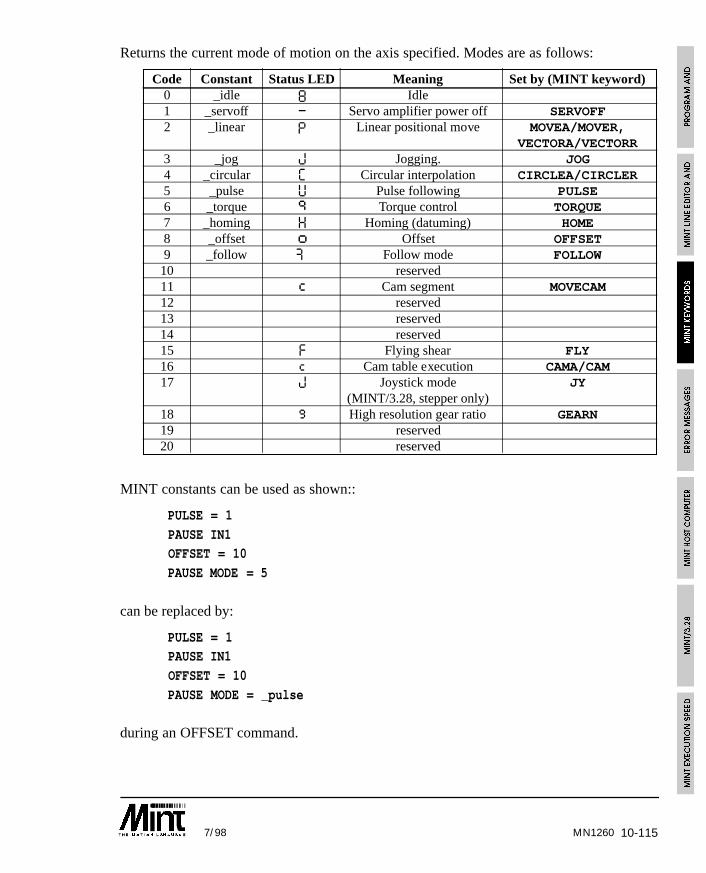
10-1157/98 MN1260
Returns the current mode of motion on the axis specified. Modes are as follows:
Code Constant Status LED Meaning Set by (MINT keyword)0 _idle 8 Idle1 _servoff – Servo amplifier power off SERVOFF2 _linear P Linear positional move MOVEA/MOVER,
VECTORA/VECTORR3 _jog J Jogging. JOG4 _circular C Circular interpolation CIRCLEA/CIRCLER5 _pulse U Pulse following PULSE6 _torque q Torque control TORQUE7 _homing H Homing (datuming) HOME8 _offset o Offset OFFSET9 _follow Æ Follow mode FOLLOW
10 reserved11 c Cam segment MOVECAM12 reserved13 reserved14 reserved15 F Flying shear FLY16 c Cam table execution CAMA/CAM17 J Joystick mode JY
(MINT/3.28, stepper only)18 g High resolution gear ratio GEARN19 reserved20 reserved
MINT constants can be used as shown::
PULSE = 1
PAUSE IN1OFFSET = 10
PAUSE MODE = 5
can be replaced by:
PULSE = 1PAUSE IN1
OFFSET = 10
PAUSE MODE = _pulse
during an OFFSET command.
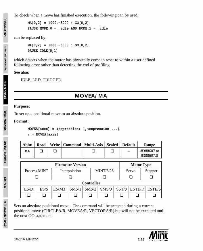
10-116 7/98MN1260
To check when a move has finished execution, the following can be used:
MA[0,2] = 1000,-3000 : GO[0,2]
PAUSE MODE.0 = _idle AND MODE.2 = _idle
can be replaced by:
MA[0,2] = 1000,-3000 : GO[0,2]
PAUSE IDLE[0,1]
which detects when the motor has physically come to reset to within a user definedfollowing error rather than detecting the end of profiling.
See also:
IDLE, LED, TRIGGER
MOVEA/MA
Purpose:
To set up a positional move to an absolute position.
Format:
MOVEA[axes] = <expression> {,<expression ...}
v = MOVEA[axis]
Abbr. Read Write Command Multi-Axis Scaled Default Range
MA ❑ ❑ ❑ ❑ – -8388607 to8388607.0
Firmware Version Motor Type
Process MINT Interpolation MINT/3.28 Servo Stepper
❑ ❑ ❑ ❑ ❑
Controller
ES/D ES/S ES/M3 SMS/1 SMS/2 SMS/3 SST/3 ESTE/D ESTE/S
❑ ❑ ❑ ❑ ❑ ❑ ❑ ❑ ❑
Sets an absolute positional move. The command will be accepted during a currentpositional move (CIRCLEA/R, MOVEA/R, VECTORA/R) but will not be executed untilthe next GO statement.
10-1177/98
Example:
MOVEA[2] = -50 : GO[2]
Moves axis two to absolute position -50 counts from datum (zero point).
MA = 100,200 : GO
moves to absolute position 100,200 from the zero position. Reading MOVEA will returnthe desired end position.
MOVEA = 100,200 : GO[0,1]
PRINT MOVEA.0;MOVEA.1
will print:
100 200
Setting AXISCON bit 3 to 1 will allow MOVEA to return the target position from theprofile generator. This value is passed to the servo/stepper control loop every cycle(typically 2ms) and determines the position of the motor.
The positional move will follow the velocity profile defined by ACCEL, SPEED andRAMP. During a positional move, the slew speed can be changed using the SPEEDkeyword. The end position of the current move can be altered using either the INCA orINCR keywords. For example:
MOVEA = 10 : GO
PAUSE IN1INCA = 20
PAUSE IDLE
will set the end position to 20 on seeing digital input 1.
Reading the OFFSET keyword during a positional move will return the remaining movelength. For example, assuming a start position of 100:
MA = 200 : GO
? OFFSET
will return 100 since this is the length of the move in operation i.e. from position 100 to200.
MA = 200 : GO
PAUSE POS >= 170
? OFFSET
will return a value of approximately 30. Note that OFFSET always returns a positivenumber regardless of the direction of motion.
MN1260
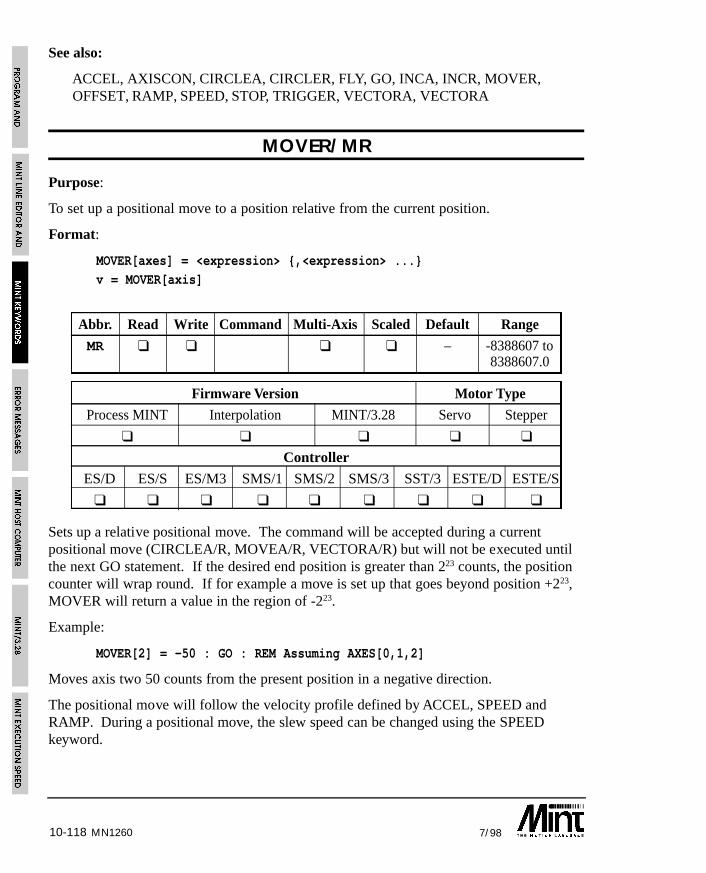
10-118 7/98MN1260
See also:
ACCEL, AXISCON, CIRCLEA, CIRCLER, FLY, GO, INCA, INCR, MOVER,OFFSET, RAMP, SPEED, STOP, TRIGGER, VECTORA, VECTORA
MOVER/MR
Purpose:
To set up a positional move to a position relative from the current position.
Format:
MOVER[axes] = <expression> {,<expression> ...}v = MOVER[axis]
Abbr. Read Write Command Multi-Axis Scaled Default Range
MR ❑ ❑ ❑ ❑ – -8388607 to8388607.0
Firmware Version Motor Type
Process MINT Interpolation MINT/3.28 Servo Stepper
❑ ❑ ❑ ❑ ❑
Controller
ES/D ES/S ES/M3 SMS/1 SMS/2 SMS/3 SST/3 ESTE/D ESTE/S
❑ ❑ ❑ ❑ ❑ ❑ ❑ ❑ ❑
Sets up a relative positional move. The command will be accepted during a currentpositional move (CIRCLEA/R, MOVEA/R, VECTORA/R) but will not be executed untilthe next GO statement. If the desired end position is greater than 223 counts, the positioncounter will wrap round. If for example a move is set up that goes beyond position +223,MOVER will return a value in the region of -223.
Example:
MOVER[2] = -50 : GO : REM Assuming AXES[0,1,2]
Moves axis two 50 counts from the present position in a negative direction.
The positional move will follow the velocity profile defined by ACCEL, SPEED andRAMP. During a positional move, the slew speed can be changed using the SPEEDkeyword.
10-1197/98
The end position of the current move can be altered using either the INCA or INCRkeywords. For example:
MOVER = 10 : GO
PAUSE IN1INCR = 20
PAUSE IDLE
will set a relative end position of 20 on seeing digital input 1.
Reading the OFFSET keyword during a positional move will return the remaining movelength. For example:
MR = 200 : GO
? OFFSET
will return 200 i.e. the length of the move in operation.
MR = 200 : GOPAUSE POS >= 170
? OFFSET
will return a value of approximately 30. Note that OFFSET always returns a positivenumber regardless of the direction of motion.
The OFFSET keyword is useful in indexing applications to determine how much of theindex is remaining. For example: in an indexing application, an output must be set 30mmbefore the end of the move where each index is 100mm in length:
LOOP
MOVER = 100 : GOPAUSE OFFSET <= 30 : REM Wait for 30mm before end
OUT1 = 1 : REM Set output
PAUSE IDLE : REM Wait to stop
OUT1 = 0 : REM Clear outputENDL
See also:
ACCEL, CIRCLEA, CIRCLER, GO, INCA, INCR, MOVEA, OFFSET, RAMP,SPEED, STOP, TRIGGER, VECTORA, VECTORA
MN1260
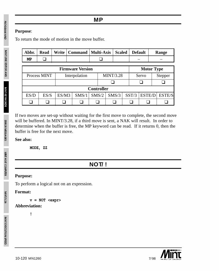
10-120 7/98MN1260
MP
Purpose:
To return the mode of motion in the move buffer.
Abbr. Read Write Command Multi-Axis Scaled Default Range
MP ❑ ❑ – –
Firmware Version Motor Type
Process MINT Interpolation MINT/3.28 Servo Stepper
❑ ❑ ❑
Controller
ES/D ES/S ES/M3 SMS/1 SMS/2 SMS/3 SST/3 ESTE/D ESTE/S
❑ ❑ ❑ ❑ ❑ ❑ ❑ ❑ ❑
If two moves are set-up without waiting for the first move to complete, the second movewill be buffered. In MINT/3.28, if a third move is sent, a NAK will result. In order todetermine when the buffer is free, the MP keyword can be read. If it returns 0, then thebuffer is free for the next move.
See also:
MODE, ZZ
NOT/!
Purpose:
To perform a logical not on an expression.
Format:
v = NOT <expr>
Abbreviation:
!
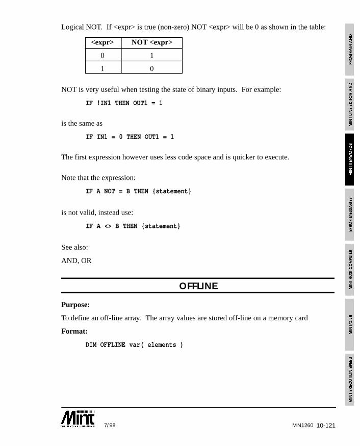
10-1217/98 MN1260
Logical NOT. If <expr> is true (non-zero) NOT <expr> will be 0 as shown in the table:
<expr> NOT <expr>
0 1
1 0
NOT is very useful when testing the state of binary inputs. For example:
IF !IN1 THEN OUT1 = 1
is the same as
IF IN1 = 0 THEN OUT1 = 1
The first expression however uses less code space and is quicker to execute.
Note that the expression:
IF A NOT = B THEN {statement}
is not valid, instead use:
IF A <> B THEN {statement}
See also:
AND, OR
OFFLINE
Purpose:
To define an off-line array. The array values are stored off-line on a memory card
Format:
DIM OFFLINE var( elements )
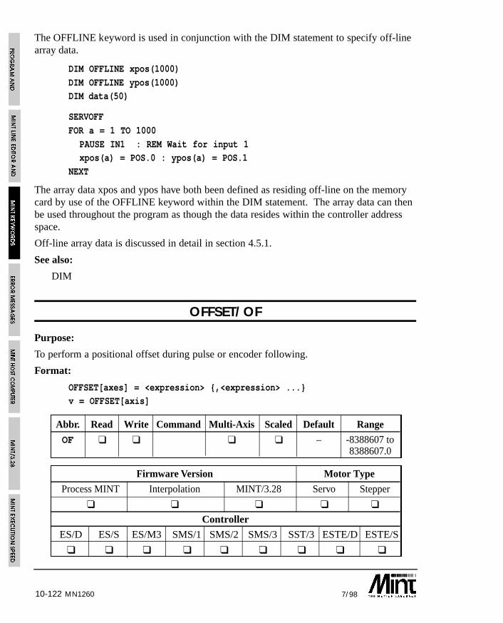
10-122 7/98MN1260
The OFFLINE keyword is used in conjunction with the DIM statement to specify off-linearray data.
DIM OFFLINE xpos(1000)
DIM OFFLINE ypos(1000)DIM data(50)
SERVOFF
FOR a = 1 TO 1000
PAUSE IN1 : REM Wait for input 1xpos(a) = POS.0 : ypos(a) = POS.1
NEXT
The array data xpos and ypos have both been defined as residing off-line on the memorycard by use of the OFFLINE keyword within the DIM statement. The array data can thenbe used throughout the program as though the data resides within the controller addressspace.
Off-line array data is discussed in detail in section 4.5.1.
See also:
DIM
OFFSET/OF
Purpose:
To perform a positional offset during pulse or encoder following.
Format:
OFFSET[axes] = <expression> {,<expression> ...}v = OFFSET[axis]
Abbr. Read Write Command Multi-Axis Scaled Default Range
OF ❑ ❑ ❑ ❑ – -8388607 to8388607.0
Firmware Version Motor Type
Process MINT Interpolation MINT/3.28 Servo Stepper
❑ ❑ ❑ ❑ ❑
Controller
ES/D ES/S ES/M3 SMS/1 SMS/2 SMS/3 SST/3 ESTE/D ESTE/S
❑ ❑ ❑ ❑ ❑ ❑ ❑ ❑ ❑
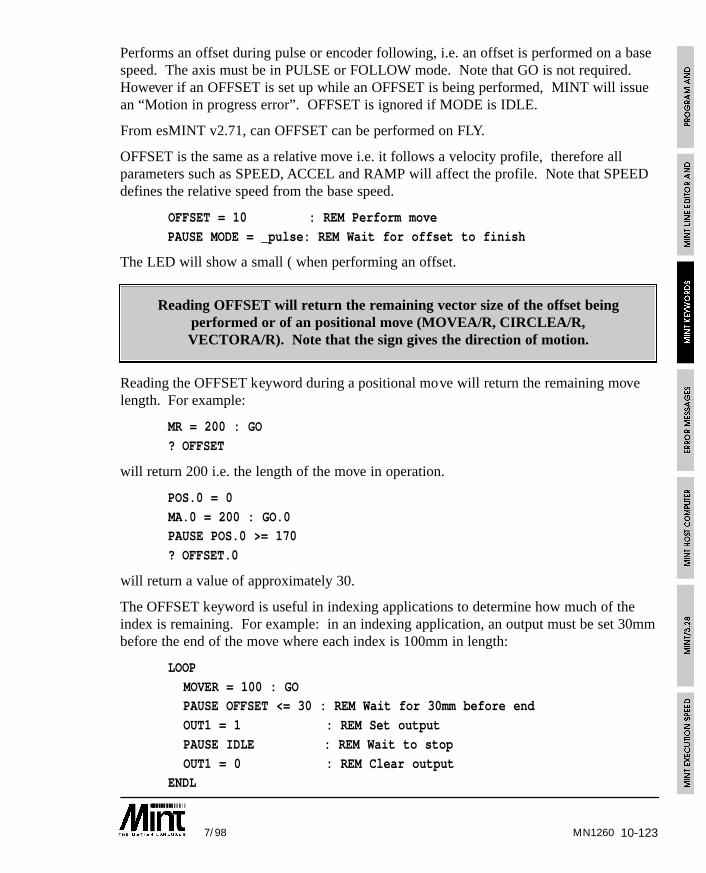
10-1237/98
Performs an offset during pulse or encoder following, i.e. an offset is performed on a basespeed. The axis must be in PULSE or FOLLOW mode. Note that GO is not required.However if an OFFSET is set up while an OFFSET is being performed, MINT will issuean “Motion in progress error”. OFFSET is ignored if MODE is IDLE.
From esMINT v2.71, can OFFSET can be performed on FLY.
OFFSET is the same as a relative move i.e. it follows a velocity profile, therefore allparameters such as SPEED, ACCEL and RAMP will affect the profile. Note that SPEEDdefines the relative speed from the base speed.
OFFSET = 10 : REM Perform move
PAUSE MODE = _pulse: REM Wait for offset to finish
The LED will show a small ( when performing an offset.
Reading OFFSET will return the remaining vector size of the offset beingperformed or of an positional move (MOVEA/R, CIRCLEA/R,VECTORA/R). Note that the sign gives the direction of motion.
Reading the OFFSET keyword during a positional move will return the remaining movelength. For example:
MR = 200 : GO
? OFFSET
will return 200 i.e. the length of the move in operation.
POS.0 = 0
MA.0 = 200 : GO.0PAUSE POS.0 >= 170
? OFFSET.0
will return a value of approximately 30.
The OFFSET keyword is useful in indexing applications to determine how much of theindex is remaining. For example: in an indexing application, an output must be set 30mmbefore the end of the move where each index is 100mm in length:
LOOP
MOVER = 100 : GOPAUSE OFFSET <= 30 : REM Wait for 30mm before end
OUT1 = 1 : REM Set output
PAUSE IDLE : REM Wait to stop
OUT1 = 0 : REM Clear outputENDL
MN1260
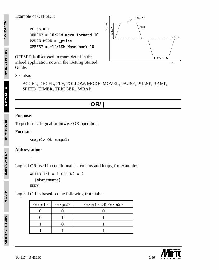
10-124 7/98
Example of OFFSET:
PULSE = 1
OFFSET = 10:REM move forward 10PAUSE MODE = _pulse
OFFSET = -10:REM Move back 10
OFFSET is discussed in more detail in theinfeed application note in the Getting StartedGuide.
See also:
ACCEL, DECEL, FLY, FOLLOW, MODE, MOVER, PAUSE, PULSE, RAMP,SPEED, TIMER, TRIGGER, WRAP
OR/|
Purpose:
To perform a logical or bitwise OR operation.
Format:
<expr1> OR <expr1>
Abbreviation:
|
Logical OR used in conditional statements and loops, for example:
WHILE IN1 = 1 OR IN2 = 0
{statements}
ENDW
Logical OR is based on the following truth table
<expr1> <expr2> <expr1> OR <expr2>
0 0 0
0 1 1
1 0 1
1 1 1
MN1260
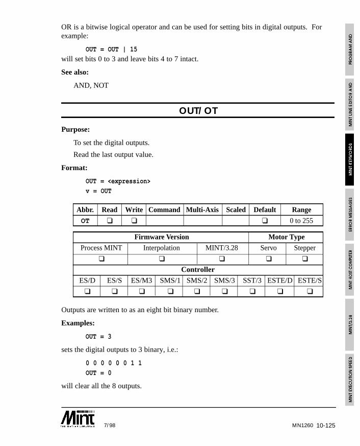
10-1257/98 MN1260
OR is a bitwise logical operator and can be used for setting bits in digital outputs. Forexample:
OUT = OUT | 15
will set bits 0 to 3 and leave bits 4 to 7 intact.
See also:
AND, NOT
OUT/OT
Purpose:
To set the digital outputs.
Read the last output value.
Format:
OUT = <expression>
v = OUT
Abbr. Read Write Command Multi-Axis Scaled Default Range
OT ❑ ❑ ❑ 0 to 255
Firmware Version Motor Type
Process MINT Interpolation MINT/3.28 Servo Stepper
❑ ❑ ❑ ❑ ❑
Controller
ES/D ES/S ES/M3 SMS/1 SMS/2 SMS/3 SST/3 ESTE/D ESTE/S
❑ ❑ ❑ ❑ ❑ ❑ ❑ ❑ ❑
Outputs are written to as an eight bit binary number.
Examples:
OUT = 3
sets the digital outputs to 3 binary, i.e.:
0 0 0 0 0 0 1 1
OUT = 0
will clear all the 8 outputs.
10-126 7/98
Alternatively binary numbers can be used to set the outputs.
Example:
OUT = 011 : REM Same as OUT = 3
Reading OUT will return the last value written to the digital outputs. For example:
OUT = OUT & 15
will clear output bits 4 to 7 while retaining bits 0 to 3.
Individual bits can be set by adding the bit number to the OUT keyword. For example:
OUT2 = 1
will set output 2.
Using the dot notation, it is also possible to set an output bit using a variable as follows:
a = 1
OUT.a = 0
will clear output bit 1. Note that if a lies outside the range 0 to 7, an “Out of Range” errorwill occur.
RESET will set all the outputs to zero (this is equivalent to OUT = 0).
SmartMove provides over current, over temperature and short circuit protection on theoutputs. If an error occurs, the ONERROR routine will be called with an ERROR valueof 13 and ERR value of 15. The error condition can be reset using the RESET andCANCEL command.
See also:
BOOSTOFF, BOOSTON, IN, OUT0..7, XIO, XOUT
MN1260
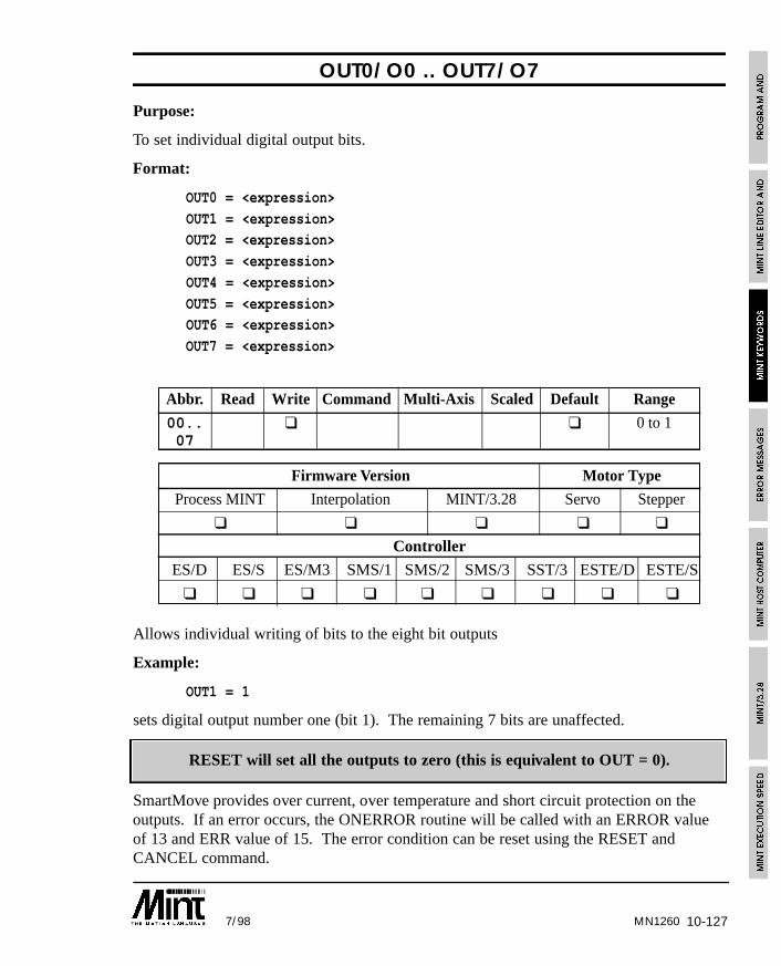
10-1277/98 MN1260
OUT0/O0 .. OUT7/O7
Purpose:
To set individual digital output bits.
Format:
OUT0 = <expression>
OUT1 = <expression>OUT2 = <expression>
OUT3 = <expression>
OUT4 = <expression>
OUT5 = <expression>OUT6 = <expression>
OUT7 = <expression>
Abbr. Read Write Command Multi-Axis Scaled Default Range
00.. ❑ ❑ 0 to 107
Firmware Version Motor Type
Process MINT Interpolation MINT/3.28 Servo Stepper
❑ ❑ ❑ ❑ ❑
Controller
ES/D ES/S ES/M3 SMS/1 SMS/2 SMS/3 SST/3 ESTE/D ESTE/S
❑ ❑ ❑ ❑ ❑ ❑ ❑ ❑ ❑
Allows individual writing of bits to the eight bit outputs
Example:
OUT1 = 1
sets digital output number one (bit 1). The remaining 7 bits are unaffected.
RESET will set all the outputs to zero (this is equivalent to OUT = 0).
SmartMove provides over current, over temperature and short circuit protection on theoutputs. If an error occurs, the ONERROR routine will be called with an ERROR valueof 13 and ERR value of 15. The error condition can be reset using the RESET andCANCEL command.
10-128 7/98
See also:
BOOSTOFF, BOOSTON, IN, OUT, XIO, XOUT
PAUSE
Purpose:
To pause program execution until a condition becomes true.
Format:
PAUSE <condition>
Execution is paused until the condition is true, where the condition is any valid MINTexpression. This has many uses in for example synchronizing motion or waiting forinputs.
PAUSE I1 = 1
pause until input bit 1 equals 1
PAUSE I1
has the same effect but will respond quicker to the input.
Pause can also be used to respond to edges on inputs. For example:
PAUSE IN1
PAUSE !IN1
this will wait for a falling edge on input 1.
PAUSE POS > 300
pause until position is greater than 300
PAUSE is more commonly used to wait for the axis to become idle.
PAUSE IDLE[0,1]
This will wait for both axis 0 and axis 1 to become idle before executing the next programstatement.
PAUSE INKEY
Will wait for any key to pressed at the user terminal. Alternatively:
PAUSE IK = ‘y’
MN1260
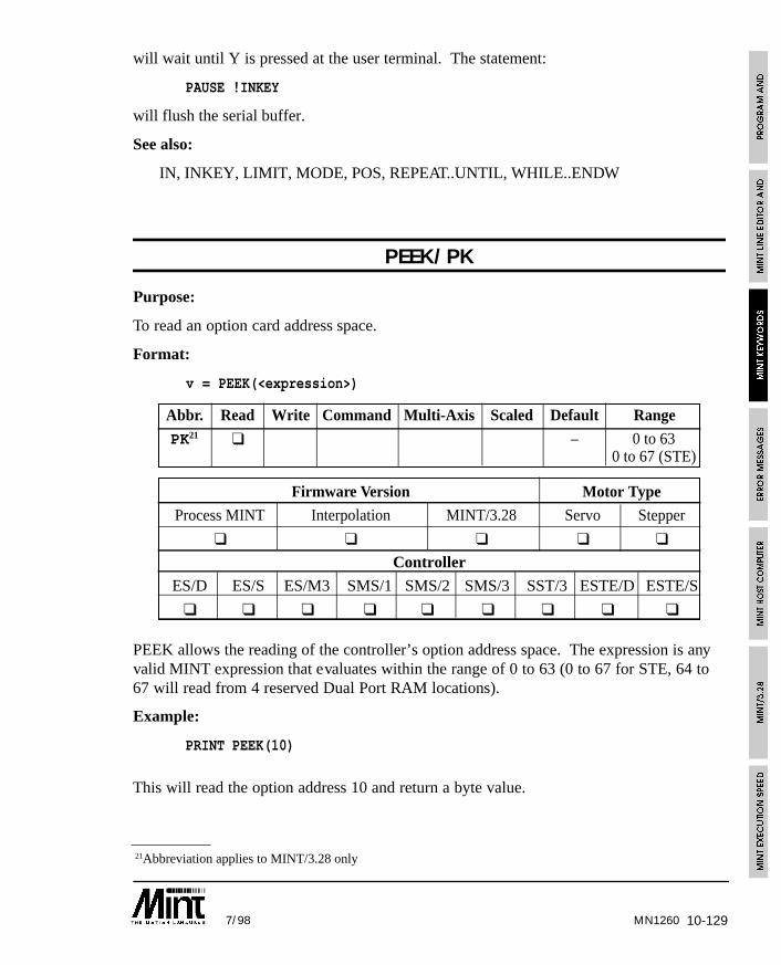
10-1297/98 MN1260
21Abbreviation applies to MINT/3.28 only
will wait until Y is pressed at the user terminal. The statement:
PAUSE !INKEY
will flush the serial buffer.
See also:
IN, INKEY, LIMIT, MODE, POS, REPEAT..UNTIL, WHILE..ENDW
PEEK/PK
Purpose:
To read an option card address space.
Format:
v = PEEK(<expression>)
Abbr. Read Write Command Multi-Axis Scaled Default Range
PK21 ❑ – 0 to 630 to 67 (STE)
Firmware Version Motor Type
Process MINT Interpolation MINT/3.28 Servo Stepper
❑ ❑ ❑ ❑ ❑
Controller
ES/D ES/S ES/M3 SMS/1 SMS/2 SMS/3 SST/3 ESTE/D ESTE/S
❑ ❑ ❑ ❑ ❑ ❑ ❑ ❑ ❑
PEEK allows the reading of the controller’s option address space. The expression is anyvalid MINT expression that evaluates within the range of 0 to 63 (0 to 67 for STE, 64 to67 will read from 4 reserved Dual Port RAM locations).
Example:
PRINT PEEK(10)
This will read the option address 10 and return a byte value.
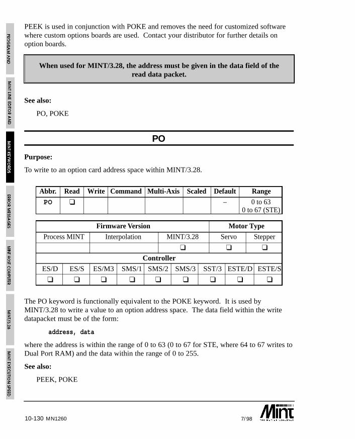
10-130 7/98MN1260
PEEK is used in conjunction with POKE and removes the need for customized softwarewhere custom options boards are used. Contact your distributor for further details onoption boards.
When used for MINT/3.28, the address must be given in the data field of theread data packet.
See also:
PO, POKE
PO
Purpose:
To write to an option card address space within MINT/3.28.
Abbr. Read Write Command Multi-Axis Scaled Default Range
PO ❑ – 0 to 630 to 67 (STE)
Firmware Version Motor Type
Process MINT Interpolation MINT/3.28 Servo Stepper
❑ ❑ ❑
Controller
ES/D ES/S ES/M3 SMS/1 SMS/2 SMS/3 SST/3 ESTE/D ESTE/S
❑ ❑ ❑ ❑ ❑ ❑ ❑ ❑ ❑
The PO keyword is functionally equivalent to the POKE keyword. It is used byMINT/3.28 to write a value to an option address space. The data field within the writedatapacket must be of the form:
address, data
where the address is within the range of 0 to 63 (0 to 67 for STE, where 64 to 67 writes toDual Port RAM) and the data within the range of 0 to 255.
See also:
PEEK, POKE
10-1317/98
POFF
Purpose:
To turn the command line and INPUT prompt off.
Format:
POFF
Turns P> or C> user prompt off, useful for host computer communications. Will also turnthe INPUT prompt off.
ECHO can be used to turn off echoing from the commands line and the echoing of errormessages to the terminal.
See also:
ECHO, PON
POKE
Purpose:
To write a byte value to the option card address space.
Format:
POKE <address>,<expression>
Writes a byte value to the option board address space. The address can be any validMINT expression as long as its evaluates within the range of 0 to 63 (0 to 67 for STE, 64to 67 will write to 4 reserved Dual Port RAM locations). The expression is the byte valueyou wish to write, in the range of 0 to 255.
Example:
POKE 1,127
will write 127 to option address 1.
POKE is used in conjunction with PEEK and removes the need for customized softwarewhere custom options boards are used. Contact your distributor for further details onoption boards.
See also:
PEEK
MN1260

10-132 7/98MN1260
PON
Purpose:
To turn the command line and INPUT prompt on.
Format:
PON
Turns P> or C> user prompt on. Also turn the INPUT (?) prompt on. PON is the defaulton power up.
See also:
ECHO, POFF
POS/PS
Purpose:
To read the instantaneous axis position.
To set the axis position.
Format:
POS[axes] = <expression> {,<expression> ...}
v = POS[axis]
Abbr. Read Write Command Multi-Axis Scaled Default Range
PS ❑ ❑ ❑ ❑ – -8388607.0 to8388607.0
Firmware Version Motor Type
Process MINT Interpolation MINT/3.28 Servo Stepper
❑ ❑ ❑ ❑ ❑
Controller
ES/D ES/S ES/M3 SMS/1 SMS/2 SMS/3 SST/3 ESTE/D ESTE/S
❑ ❑ ❑ ❑ ❑ ❑ ❑ ❑ ❑
Returns the instantaneous axis position.

10-1337/98
Example:
MR = 100 : GO
WHILE !IDLE? POS; : BOL
ENDW
This will print the position to the user terminal until the axis is idle.
Writing to POS will set the position to the value of the expression. Make sure the axis isidle before setting the new position. If the axis is currently executing a move, an errorwill be generated. Using POS with HOME allows you to set your own datum positions.For example:
HOME = 1,1 : REM Datum axesPAUSE IDLE[0,1] : REM Wait for axes to stop
POS = 100,200 : REM Set new datum positions
The ENCODER keyword can be used to provide a form of closed loop on a stepper motor.If we assume that we have the same number of quad count to steps on the stepper motor,the following subroutine, correction, can be used to correct for any missing steps:
< MANUAL\CORRECT.MNT
SF = 1MA.0 = 1000 : GO.0
PAUSE IDLE.0
GOSUB correction
END
#correction
REM Read the position we should be at
finalPos = POS.0
REM Keep correcting until we get to the position
WHILE ENCODER.0 <> finalPos
MR.0 = finalPos - ENCODER.0 : GO.0PAUSE IDLE.0
ENDW
REM Reset the position to the actual encoder positionPOS.0 = ENCODER.0
RETURN
MN1260
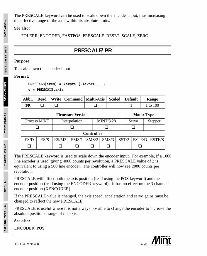
10-134 7/98MN1260
The PRESCALE keyword can be used to scale down the encoder input, thus increasingthe effective range of the axis within its absolute limits.
See also:
FOLERR, ENCODER, FASTPOS, PRESCALE. RESET, SCALE, ZERO
PRESCALE/PR
Purpose:
To scale down the encoder input
Format:
PRESCALE[axes] = <expr> {,<expr> ...}
v = PRESCALE.axis
Abbr. Read Write Command Multi-Axis Scaled Default Range
PR ❑ ❑ ❑ 1 1 to 100
Firmware Version Motor Type
Process MINT Interpolation MINT/3.28 Servo Stepper
❑ ❑ ❑ ❑
Controller
ES/D ES/S ES/M3 SMS/1 SMS/2 SMS/3 SST/3 ESTE/D ESTE/S
❑ ❑ ❑ ❑ ❑ ❑
The PRESCALE keyword is used to scale down the encoder input. For example, if a 1000line encoder is used, giving 4000 counts per revolution, a PRESCALE value of 2 isequivalent to using a 500 line encoder. The controller will now see 2000 counts perrevolution.
PRESCALE will affect both the axis position (read using the POS keyword) and theencoder position (read using the ENCODER keyword). It has no effect on the 3 channelencoder position (XENCODER).
If the PRESCALE value is changed, the axis speed, acceleration and servo gains must bechanged to reflect the new PRESCALE.
PRESCALE is useful where it is not always possible to change the encoder to increase theabsolute positional range of the axis.
See also:
ENCODER, POS
10-1357/98
PRINT/?
Purpose:
To display expressions and strings to the terminal.
Format:
PRINT argument list {USING <int> {,<frac>}}
Abbreviation:
?
Strings may be printed with the PRINT command delimited by double quotes.Expressions and strings may be separated by semicolons or commas. A comma will causethe next argument to print directly after the previous one; a semicolon will print the nextargument at the next tab position, where each tab position is at every 8 characters. PRINTmay be abbreviated by a question mark (?).
Example:
PRINT “a = “,a,” POS = “,POS[0]
or
? “a = “,a,” POS = “,POS[0]
Example 2:
LOOP : ? POS[0];POS[1];POS[2]; : BOL : ENDL
will repeatedly print the position of axes 0, 1 and 2 to the same line. This is achieved byuse of the BOL (Beginning Of Line) keyword. Note the use of semicolon to suppress linefeeding. This is especially useful when writing to the LCD display. If a carriage return ifperformed on the last line of the display, the display will be cleared. Use a comma tosuppress this.
The USING parameter allows for formatted output. <int> is the number of decimalplaces to print and <frac> is the number of fractional places to print. The printed numberis prefixed with zeroes where necessary.
If <int> is positive, the number will be printed without a sign. If <int> is negative, thenumber will be printed with a leading + or - sign.
MN1260
10-136 7/98
Example 3:
a = -123.5
PRINT a USING -5,1
will display:
-00123.5
Example 4:
a = 123.5
PRINT a USING 5,2
will display:
00123.50
Example 5:
a = 123.5
PRINT a USING 4
will display:
0123
Fractional numbers are not rounded up.
In addition to the PRINT keyword, MINT also has the BINARY and the LINE keywordsfor terminal output. The BINARY keyword is used to print 8 bit binary numbers. TheLINE keyword is used, in conjunction with the LCD display, to write to a specified lineand clearing all characters to the end of that line. LINE will replace:
LOCATE 1,2 : REM Locate to line 2PRINT “A Message “ REM Print message and clear rest ofline
with:
LINE 2, “A Message”
LINE accepts all the parameters that PRINT uses.
See also:
BINARY, CHR, INPUT, INKEY, LINE, LOCATE
MN1260
10-1377/98
PROTECT
Purpose:
To password protect the program and configuration files.
Format:
PROTECT password
The PROTECT keyword provides password protection for the program and configurationfiles. The keyword PROTECT must be placed on the first line of the program file (not theconfiguration file) followed by the password. When this has been entered into theprogram, any editor commands used will require the password to be entered. On issuingan editor command, the prompt “password” is displayed requesting a password. Enterthe correct password for the operation to be carried out (note that *’s are printed to theterminal in place of the characters pressed).
Editor commands affected by password control are:
DEL, EDIT, INS, LIST, LOAD, NEW, SAVE
Notes:
• The keyword PROTECT must be in upper case otherwise it will be ignored.
• The password is case sensitive and will accept letters, numbers, spaces andpunctuation. A password length of 20 characters is allowed.
• Only the keyword PROTECT and the password must exist on line 1 of the program.Additional keywords such as REM cannot be placed on this line since these willbecome part of the password.
• In order to gain full control of the editor without entering the password each time, thePROTECT keyword must be removed. This can be achieved by either placing REMbefore PROTECT or inserting a line at line 1 before the PROTECT keyword.
• Programs cannot be loaded and saved using cTERM with password protection inoperation. The loading and saving of array data is not affected by passwordprotection.
Example:
PROTECT abcREM Program example
GOSUB init
GOSUB main
#init
...
MN1260
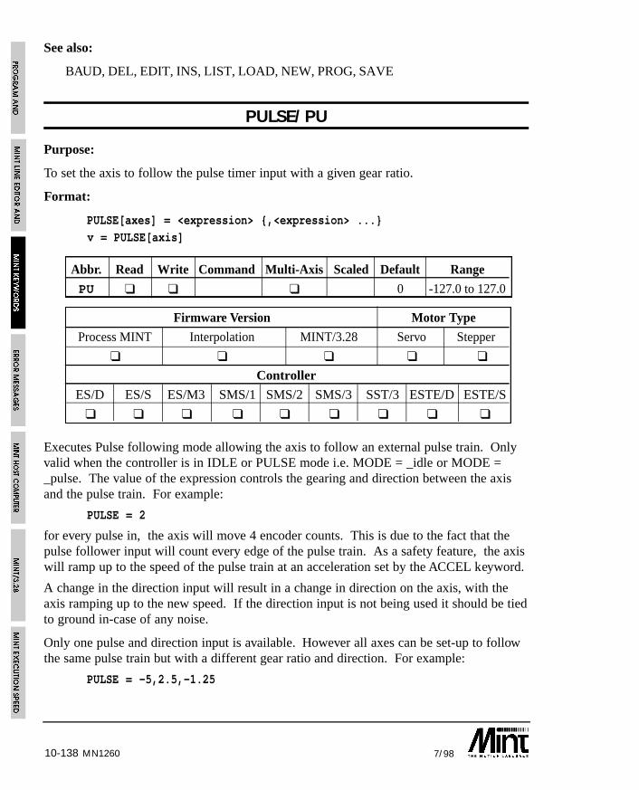
MN126010-138 7/98
See also:
BAUD, DEL, EDIT, INS, LIST, LOAD, NEW, PROG, SAVE
PULSE/PU
Purpose:
To set the axis to follow the pulse timer input with a given gear ratio.
Format:
PULSE[axes] = <expression> {,<expression> ...}v = PULSE[axis]
Abbr. Read Write Command Multi-Axis Scaled Default Range
PU ❑ ❑ ❑ 0 -127.0 to 127.0
Firmware Version Motor Type
Process MINT Interpolation MINT/3.28 Servo Stepper
❑ ❑ ❑ ❑ ❑
Controller
ES/D ES/S ES/M3 SMS/1 SMS/2 SMS/3 SST/3 ESTE/D ESTE/S
❑ ❑ ❑ ❑ ❑ ❑ ❑ ❑ ❑
Executes Pulse following mode allowing the axis to follow an external pulse train. Onlyvalid when the controller is in IDLE or PULSE mode i.e. MODE = _idle or MODE =_pulse. The value of the expression controls the gearing and direction between the axisand the pulse train. For example:
PULSE = 2
for every pulse in, the axis will move 4 encoder counts. This is due to the fact that thepulse follower input will count every edge of the pulse train. As a safety feature, the axiswill ramp up to the speed of the pulse train at an acceleration set by the ACCEL keyword.
A change in the direction input will result in a change in direction on the axis, with theaxis ramping up to the new speed. If the direction input is not being used it should be tiedto ground in-case of any noise.
Only one pulse and direction input is available. However all axes can be set-up to followthe same pulse train but with a different gear ratio and direction. For example:
PULSE = -5,2.5,-1.25
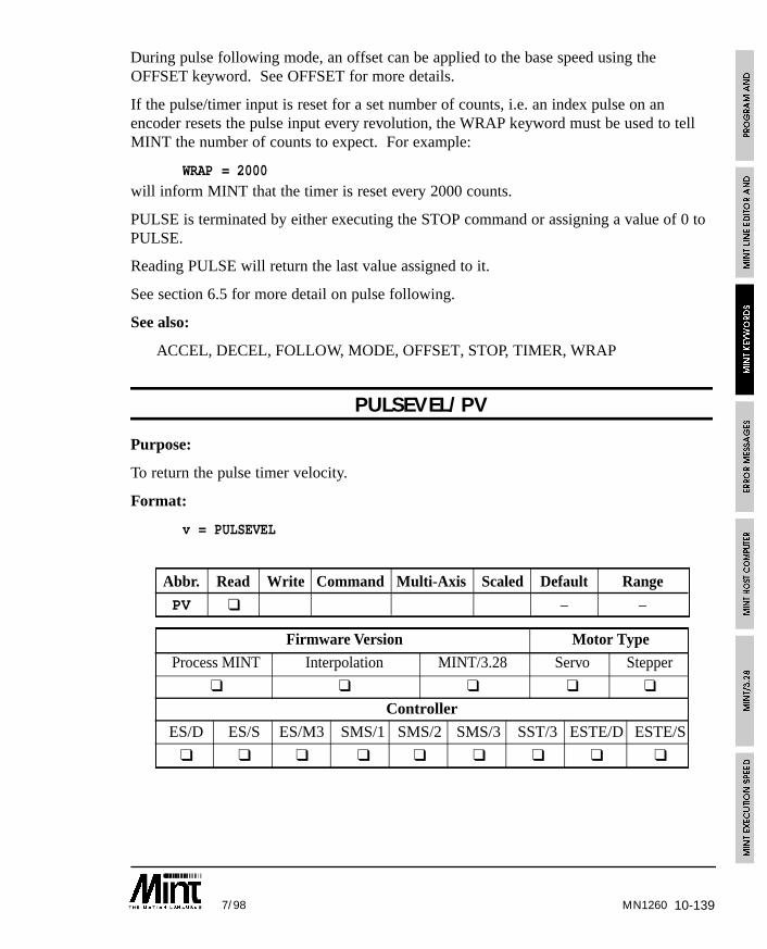
10-1397/98 MN1260
During pulse following mode, an offset can be applied to the base speed using theOFFSET keyword. See OFFSET for more details.
If the pulse/timer input is reset for a set number of counts, i.e. an index pulse on anencoder resets the pulse input every revolution, the WRAP keyword must be used to tellMINT the number of counts to expect. For example:
WRAP = 2000
will inform MINT that the timer is reset every 2000 counts.
PULSE is terminated by either executing the STOP command or assigning a value of 0 toPULSE.
Reading PULSE will return the last value assigned to it.
See section 6.5 for more detail on pulse following.
See also:
ACCEL, DECEL, FOLLOW, MODE, OFFSET, STOP, TIMER, WRAP
PULSEVEL/PV
Purpose:
To return the pulse timer velocity.
Format:
v = PULSEVEL
Abbr. Read Write Command Multi-Axis Scaled Default Range
PV ❑ – –
Firmware Version Motor Type
Process MINT Interpolation MINT/3.28 Servo Stepper
❑ ❑ ❑ ❑ ❑
Controller
ES/D ES/S ES/M3 SMS/1 SMS/2 SMS/3 SST/3 ESTE/D ESTE/S
❑ ❑ ❑ ❑ ❑ ❑ ❑ ❑ ❑
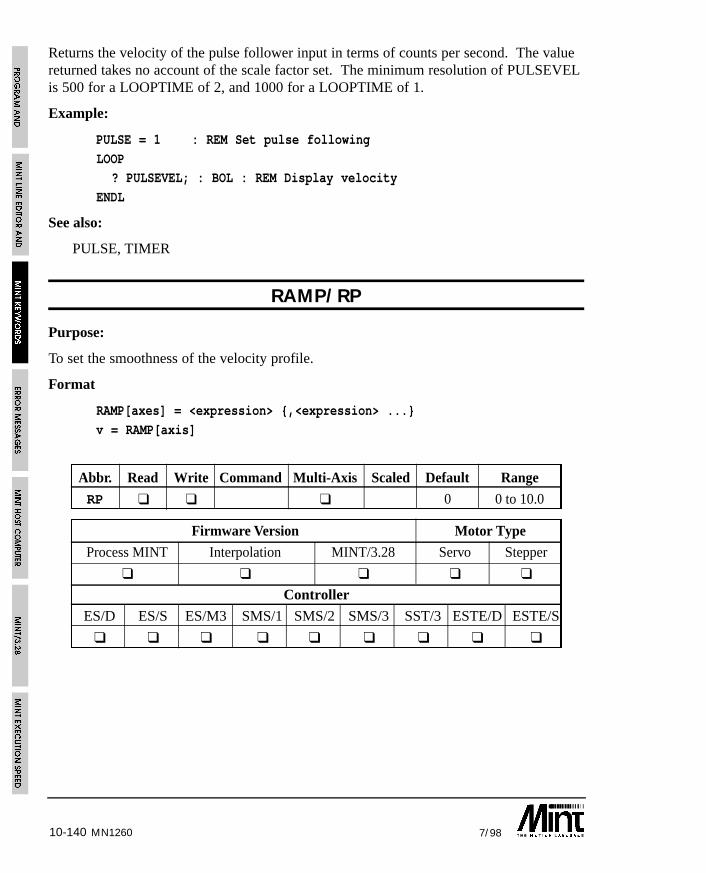
10-140 7/98MN1260
Returns the velocity of the pulse follower input in terms of counts per second. The valuereturned takes no account of the scale factor set. The minimum resolution of PULSEVELis 500 for a LOOPTIME of 2, and 1000 for a LOOPTIME of 1.
Example:
PULSE = 1 : REM Set pulse following
LOOP? PULSEVEL; : BOL : REM Display velocity
ENDL
See also:
PULSE, TIMER
RAMP/RP
Purpose:
To set the smoothness of the velocity profile.
Format
RAMP[axes] = <expression> {,<expression> ...}
v = RAMP[axis]
Abbr. Read Write Command Multi-Axis Scaled Default Range
RP ❑ ❑ ❑ 0 0 to 10.0
Firmware Version Motor Type
Process MINT Interpolation MINT/3.28 Servo Stepper
❑ ❑ ❑ ❑ ❑
Controller
ES/D ES/S ES/M3 SMS/1 SMS/2 SMS/3 SST/3 ESTE/D ESTE/S
❑ ❑ ❑ ❑ ❑ ❑ ❑ ❑ ❑
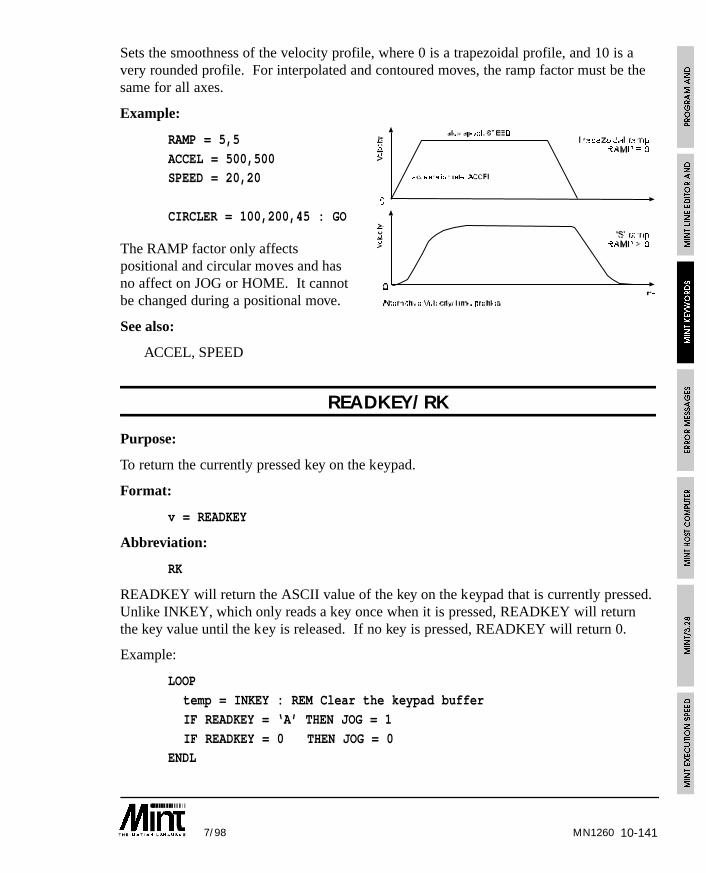
10-1417/98
Sets the smoothness of the velocity profile, where 0 is a trapezoidal profile, and 10 is avery rounded profile. For interpolated and contoured moves, the ramp factor must be thesame for all axes.
Example:
RAMP = 5,5
ACCEL = 500,500SPEED = 20,20
CIRCLER = 100,200,45 : GO
The RAMP factor only affectspositional and circular moves and hasno affect on JOG or HOME. It cannotbe changed during a positional move.
See also:
ACCEL, SPEED
READKEY/RK
Purpose:
To return the currently pressed key on the keypad.
Format:
v = READKEY
Abbreviation:
RK
READKEY will return the ASCII value of the key on the keypad that is currently pressed.Unlike INKEY, which only reads a key once when it is pressed, READKEY will returnthe key value until the key is released. If no key is pressed, READKEY will return 0.
Example:
LOOP
temp = INKEY : REM Clear the keypad buffer
IF READKEY = ‘A’ THEN JOG = 1
IF READKEY = 0 THEN JOG = 0ENDL
MN1260
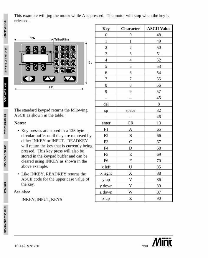
MN126010-142 7/98
This example will jog the motor while A is pressed. The motor will stop when the key isreleased.
The standard keypad returns the followingASCII as shown in the table:
Notes:
• Key presses are stored in a 128 bytecircular buffer until they are removed byeither INKEY or INPUT. READKEYwill return the key that is currently beingpressed. This key press will also bestored in the keypad buffer and can becleared using INKEY as shown in theabove example.
• Like INKEY, READKEY returns theASCII code for the upper case value ofthe key.
See also:
INKEY, INPUT, KEYS
Key Character ASCII Value
0 0 48
1 1 49
2 2 50
3 3 51
4 4 52
5 5 53
6 6 54
7 7 55
8 8 56
9 9 57
– – 45
del 8
sp space 32
– – 46
enter CR 13
F1 A 65
F2 B 66
F3 C 67
F4 D 68
F5 E 69
F6 F 70
x left U 85
x right X 88
y up V 86
y down Y 89
z down W 87
z up Z 90

10-1437/98
RELEASE
Purpose:
To clear all user variables from memory.
Format:
RELEASE
The currently defined variables are released from memory. All array values are stillmaintained in non-volatile memory and will not be cleared by RELEASE. Re-executingthe DIM statements will restore the array values.
RELEASE cannot be used within a program. Variables are defined atcompile time and RELEASE will clear them at run time.
See also:
DIM, DISPLAY
REM
Purpose:
To place comments into a program file.
Format:
REM {string}
Allows remarks to be placed in a program file. All characters after the REM until the endof line are ignored. If remarks are to be placed after a line of code, the REM should beseparated from the statement by a colon although this is not necessary. For example:
PRINT : REM this prints a blank linePRINT REM This also prints a blank line
The colon is not necessary as a consequence of the MINT code being semi-compiled atrun time. However, to aid readability and future compatibility, the colon should be used.
MN1260
10-144 7/98
REPEAT .. UNTIL
Purpose:
To perform a loop until a condition becomes true.
Format:
REPEAT
{statements}UNTIL <condition>
Executes the statements until the condition becomes true. In MINT any value other than 0is defined as true and only 0 is false. A REPEAT loop can be terminated by setting thecondition after UNTIL to zero. By defining a variable, the loop could terminate for anumber of conditions.
Example:
a = _falseREPEAT
{statements}
IF POS > 10 THEN a = _true
IF IN1 THEN a = _trueUNTIL a
A repeat loop will always execute at least once. REPEAT .. UNTIL loops can be nestedup to 10 levels.
EXIT can be used to prematurely terminate the loop.
See also:
EXIT, FOR..NEXT, LOOP..ENDL, PAUSE, WHILE..ENDW
MN1260
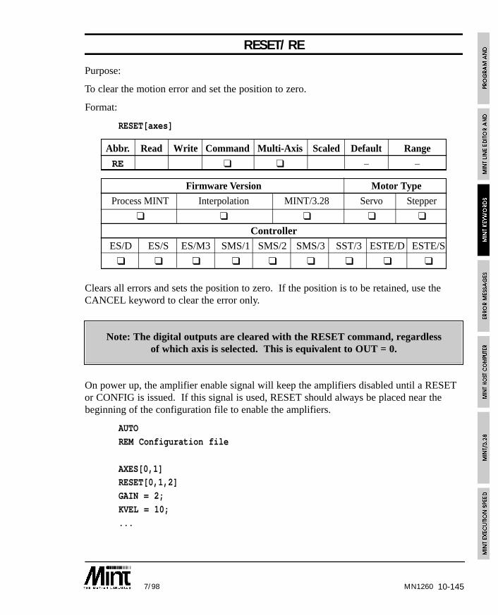
10-1457/98 MN1260
RESET/RE
Purpose:
To clear the motion error and set the position to zero.
Format:
RESET[axes]
Abbr. Read Write Command Multi-Axis Scaled Default Range
RE ❑ ❑ – –
Firmware Version Motor Type
Process MINT Interpolation MINT/3.28 Servo Stepper
❑ ❑ ❑ ❑ ❑
Controller
ES/D ES/S ES/M3 SMS/1 SMS/2 SMS/3 SST/3 ESTE/D ESTE/S
❑ ❑ ❑ ❑ ❑ ❑ ❑ ❑ ❑
Clears all errors and sets the position to zero. If the position is to be retained, use theCANCEL keyword to clear the error only.
Note: The digital outputs are cleared with the RESET command, regardlessof which axis is selected. This is equivalent to OUT = 0.
On power up, the amplifier enable signal will keep the amplifiers disabled until a RESETor CONFIG is issued. If this signal is used, RESET should always be placed near thebeginning of the configuration file to enable the amplifiers.
AUTO
REM Configuration file
AXES[0,1]RESET[0,1,2]
GAIN = 2;
KVEL = 10;
...
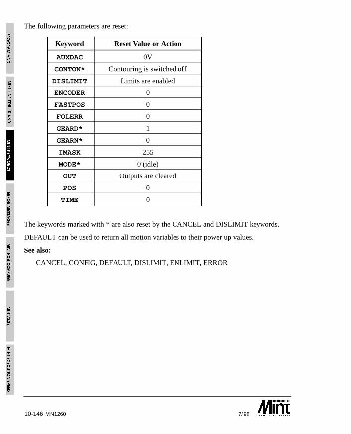
10-146 7/98MN1260
The following parameters are reset:
Keyword Reset Value or Action
AUXDAC 0V
CONTON* Contouring is switched off
DISLIMIT Limits are enabled
ENCODER 0
FASTPOS 0
FOLERR 0
GEARD* 1
GEARN* 0
IMASK 255
MODE* 0 (idle)
OUT Outputs are cleared
POS 0
TIME 0
The keywords marked with * are also reset by the CANCEL and DISLIMIT keywords.
DEFAULT can be used to return all motion variables to their power up values.
See also:
CANCEL, CONFIG, DEFAULT, DISLIMIT, ENLIMIT, ERROR
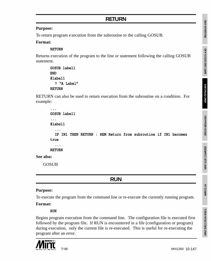
10-1477/98
RETURNPurpose:
To return program execution from the subroutine to the calling GOSUB.
Format:
RETURN
Returns execution of the program to the line or statement following the calling GOSUBstatement.
GOSUB label1END#label1
? “A Label”RETURN
RETURN can also be used to return execution from the subroutine on a condition. Forexample:
...GOSUB label1...#label1
...IF IN1 THEN RETURN : REM Return from subroutine if IN1 becomes
true...
RETURN
See also:
GOSUB
RUN
Purpose:
To execute the program from the command line or re-execute the currently running program.
Format:
RUN
Begins program execution from the command line. The configuration file is executed firstfollowed by the program file. If RUN is encountered in a file (configuration or program)during execution, only the current file is re-executed. This is useful for re-executing theprogram after an error.
MN1260
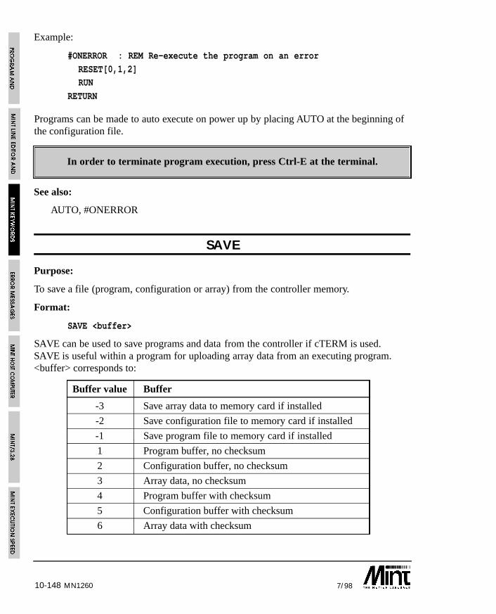
10-148 7/98MN1260
Example:
#ONERROR : REM Re-execute the program on an error
RESET[0,1,2]RUN
RETURN
Programs can be made to auto execute on power up by placing AUTO at the beginning ofthe configuration file.
In order to terminate program execution, press Ctrl-E at the terminal.
See also:
AUTO, #ONERROR
SAVE
Purpose:
To save a file (program, configuration or array) from the controller memory.
Format:
SAVE <buffer>
SAVE can be used to save programs and data from the controller if cTERM is used.SAVE is useful within a program for uploading array data from an executing program.<buffer> corresponds to:
Buffer value Buffer
-3 Save array data to memory card if installed
-2 Save configuration file to memory card if installed
-1 Save program file to memory card if installed
1 Program buffer, no checksum
2 Configuration buffer, no checksum
3 Array data, no checksum
4 Program buffer with checksum
5 Configuration buffer with checksum
6 Array data with checksum
10-1497/98
Example:
{ statements }
IF INKEY = ‘S’ THEN GOSUB saveData{ statements }
END
#saveData
TIME = 0
REPEATIF INKEY = ‘3’ THEN : ? “Ok 3”: SAVE 3
UNTIL TIME > 1000 : REM Timeout after 1000ms
RETURN
on receiving an ‘S’, the subroutine saveData will be called. If ‘3’ is received the data willbe save, otherwise the routine will time-out. This can be used with cTERM which on filesave will send down the string “SAVE” followed by “3” for array data. cTERM will thenexpect the response “Ok 3” before saving the data.
Buffer values 4 to 6 should only be used with cTERM which provides a checksum tocheck for data corruption. Always send “Ok 1” to “Ok 3” in acknowledgement and not“Ok 4” to “Ok 6”.
If the memory card is installed and AUTO is present in the configuration file, the programand config files will be copied automatically into memory. In order to save the files intothe memory card, first download them into internal memory and type the following at thecommand line:
SAVE -1
SAVE -2
The upload/download routines as used within cTERM for DOS can be found on theaccompanying diskette. These are written in Turbo C but should be portable among mostC compilers. Alternatively the MINT Interface Library provides functions for Windowsfor many of the popular development suites.
See also:
DIM, DISPLAY, LOAD
MN1260
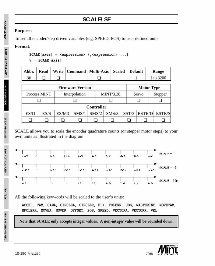
10-150 7/98MN1260
SCALE/SF
Purpose:
To set all encoder/step driven variables (e.g. SPEED, POS) to user defined units.
Format:
SCALE[axes] = <expression> {,<expression> ...}
v = SCALE[axis]
Abbr. Read Write Command Multi-Axis Scaled Default Range
SF ❑ ❑ ❑ 1 1 to 3200
Firmware Version Motor Type
Process MINT Interpolation MINT/3.28 Servo Stepper
❑ ❑ ❑ ❑ ❑
Controller
ES/D ES/S ES/M3 SMS/1 SMS/2 SMS/3 SST/3 ESTE/D ESTE/S
❑ ❑ ❑ ❑ ❑ ❑ ❑ ❑ ❑
SCALE allows you to scale the encoder quadrature counts (or stepper motor steps) to yourown units as illustrated in the diagram:
All the following keywords will be scaled to the user’s units:
ACCEL, CAM, CAMA, CIRCLEA, CIRCLER, FLY, FOLERR, JOG, MASTERINC, MOVECAM,MFOLERR, MOVEA, MOVER, OFFSET, POS, SPEED, VECTORA, VECTORR, VEL
Note that SCALE only accepts integer values. A non-integer value will be rounded down.
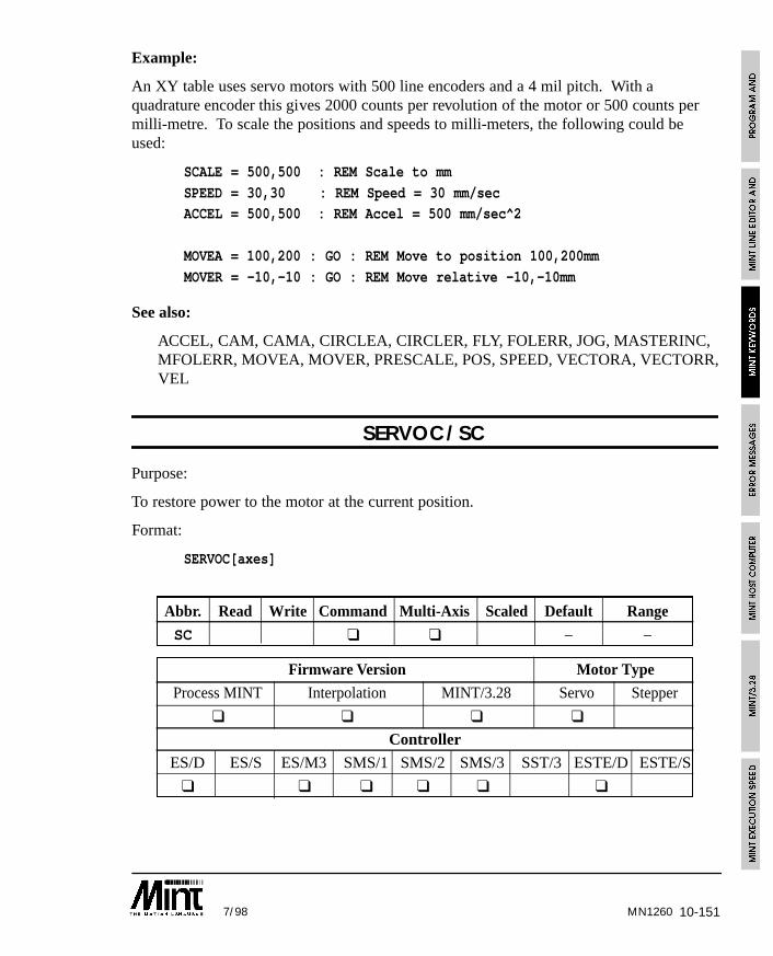
10-1517/98 MN1260
Example:
An XY table uses servo motors with 500 line encoders and a 4 mil pitch. With aquadrature encoder this gives 2000 counts per revolution of the motor or 500 counts permilli-metre. To scale the positions and speeds to milli-meters, the following could beused:
SCALE = 500,500 : REM Scale to mm
SPEED = 30,30 : REM Speed = 30 mm/secACCEL = 500,500 : REM Accel = 500 mm/sec^2
MOVEA = 100,200 : GO : REM Move to position 100,200mm
MOVER = -10,-10 : GO : REM Move relative -10,-10mm
See also:
ACCEL, CAM, CAMA, CIRCLEA, CIRCLER, FLY, FOLERR, JOG, MASTERINC,MFOLERR, MOVEA, MOVER, PRESCALE, POS, SPEED, VECTORA, VECTORR,VEL
SERVOC/SC
Purpose:
To restore power to the motor at the current position.
Format:
SERVOC[axes]
Abbr. Read Write Command Multi-Axis Scaled Default Range
SC ❑ ❑ – –
Firmware Version Motor Type
Process MINT Interpolation MINT/3.28 Servo Stepper
❑ ❑ ❑ ❑
Controller
ES/D ES/S ES/M3 SMS/1 SMS/2 SMS/3 SST/3 ESTE/D ESTE/S
❑ ❑ ❑ ❑ ❑ ❑
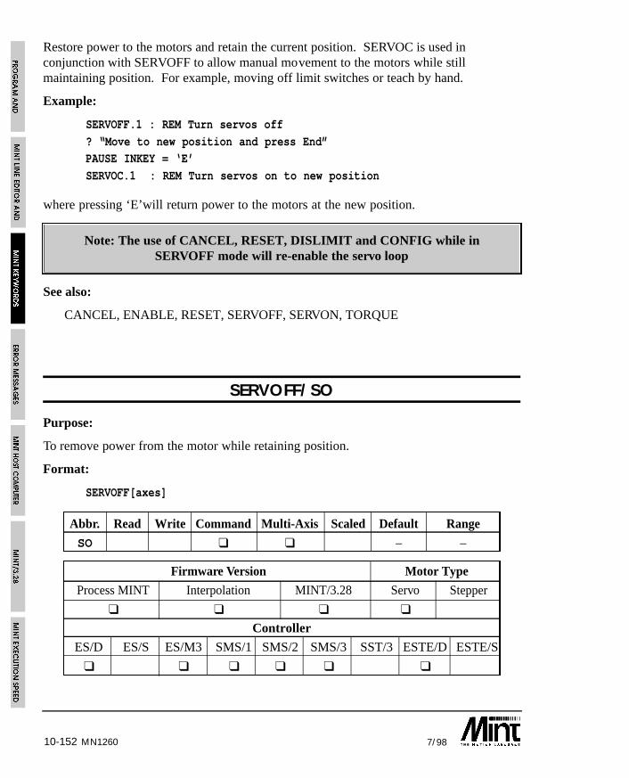
10-152 7/98MN1260
Restore power to the motors and retain the current position. SERVOC is used inconjunction with SERVOFF to allow manual movement to the motors while stillmaintaining position. For example, moving off limit switches or teach by hand.
Example:
SERVOFF.1 : REM Turn servos off
? “Move to new position and press End”PAUSE INKEY = ‘E’
SERVOC.1 : REM Turn servos on to new position
where pressing ‘E’will return power to the motors at the new position.
Note: The use of CANCEL, RESET, DISLIMIT and CONFIG while inSERVOFF mode will re-enable the servo loop
See also:
CANCEL, ENABLE, RESET, SERVOFF, SERVON, TORQUE
SERVOFF/SO
Purpose:
To remove power from the motor while retaining position.
Format:
SERVOFF[axes]
Abbr. Read Write Command Multi-Axis Scaled Default Range
SO ❑ ❑ – –
Firmware Version Motor Type
Process MINT Interpolation MINT/3.28 Servo Stepper
❑ ❑ ❑ ❑
Controller
ES/D ES/S ES/M3 SMS/1 SMS/2 SMS/3 SST/3 ESTE/D ESTE/S
❑ ❑ ❑ ❑ ❑ ❑
10-1537/98
Turns the power off to the current amplifiers allowing for manual movement of the axis.SERVOFF will display a minus sign on the LED display and MODE will return a value of 1.
The following example shows how SERVOFF can be used to manually move off a limitswitch and then restore power using SERVOC.
SERVOFF.0
PAUSE !LIMIT : REM Wait to move off limitSERVOC.0 : REM Restore power to current position.
Alternatively:
TORQUE = 0
PAUSE !LIMIT
STOP.0
will produce the same effect as the previous example.
Example 2:
During encoder following (FOLLOW), it may be necessary to turn the axis off that youare following, to avoid following errors resulting in a system shut down. The axis can beeither turned off using SERVOFF or CONFIG = _off.
SERVOFF.2 : REM Servo off axis 2
REM Could use CONFIG.2 = _off
FOLLOWAXIS.0 = 2 : REM Follow axis 2
FOLLOW.0 = 2 : REM Follow at a ratio of 2:1
SERVOFF turns off the servo control loops within the controller but will not turn off theamplifiers. When using velocity amplifiers it will be necessary to turn off the drives usingthe ENABLE keyword before turning the servo control off.
ENABLE = _off
SERVOFF
The ENABLE keyword will turn all the drives off since it controls the error output signal.
Note: The use of CANCEL, RESET, DISLIMIT and CONFIG while inSERVOFF mode will re-enable the servo loop
See also:
CANCEL, ENABLE, RESET, SERVOC, SERVON
MN1260
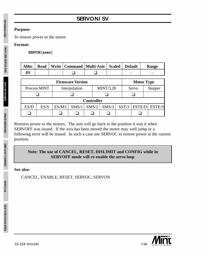
10-154 7/98MN1260
SERVON/SV
Purpose:
To restore power to the motor.
Format:
SERVON[axes]
Abbr. Read Write Command Multi-Axis Scaled Default Range
SV ❑ ❑ – –
Firmware Version Motor Type
Process MINT Interpolation MINT/3.28 Servo Stepper
❑ ❑ ❑ ❑
Controller
ES/D ES/S ES/M3 SMS/1 SMS/2 SMS/3 SST/3 ESTE/D ESTE/S
❑ ❑ ❑ ❑ ❑ ❑
Restores power to the motors. The axis will go back to the position it was it whenSERVOFF was issued. If the axis has been moved the motor may well jump or afollowing error will be issued. In such a case use SERVOC to restore power at the currentposition.
Note: The use of CANCEL, RESET, DISLIMIT and CONFIG while inSERVOFF mode will re-enable the servo loop
See also:
CANCEL, ENABLE, RESET, SERVOC, SERVON
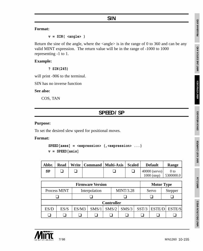
10-1557/98 MN1260
SIN
Format:
v = SIN( <angle> )
Return the sine of the angle, where the <angle> is in the range of 0 to 360 and can be anyvalid MINT expression. The return value will be in the range of -1000 to 1000representing -1 to 1.
Example:
? SIN(245)
will print -906 to the terminal.
SIN has no inverse function
See also:
COS, TAN
SPEED/SP
Purpose:
To set the desired slew speed for positional moves.
Format:
SPEED[axes] = <expression> {,<expression> ...}
v = SPEED[axis]
Abbr. Read Write Command Multi-Axis Scaled Default Range
SP ❑ ❑ ❑ ❑ 40000 (servo) 0 to1000 (step) 5300000.0
Firmware Version Motor Type
Process MINT Interpolation MINT/3.28 Servo Stepper
❑ ❑ ❑ ❑ ❑
Controller
ES/D ES/S ES/M3 SMS/1 SMS/2 SMS/3 SST/3 ESTE/D ESTE/S
❑ ❑ ❑ ❑ ❑ ❑ ❑ ❑ ❑
10-156 7/98
Sets the desired slew speed for positional moves. This variable can be changed during apositional move and the axis will control acceleration to the new SPEED at anacceleration defined by the ACCEL keyword. Deceleration is controlled with the DECELkeyword.
Example:
SCALE = 2000 : REM Scale to revs
SPEED = 20 : REM Speed = 20 revs/secMA = 10 : GO : REM Move to position 10 revs
will move to absolute position 10 revs at a speed of 20 revs/sec.
In an interpolated move the SPEED will determine the SPEED on the vector ofmovement. In order for correct motion, all axes performing interpolation must have thesame SPEED specified before the move is executed.
Example:
ACCEL = 2500,2500RAMP = 5,5
SPEED = 100,100
CIRCLEA = 100,200,270 : GO
See also:
ACCEL, ACCELTIME, AXISCON, CAM, CIRCLEA, CIRCLER, DECEL, FLY,FOLLOWAXIS, INCA, INCR, MOVEA, MOVER, OFFSET, SCALE, VECTORA,VECTORR
MN1260
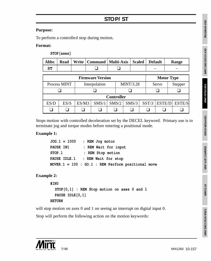
10-1577/98 MN1260
STOP/ST
Purpose:
To perform a controlled stop during motion.
Format:
STOP[axes]
Abbr. Read Write Command Multi-Axis Scaled Default Range
ST ❑ ❑ – –
Firmware Version Motor Type
Process MINT Interpolation MINT/3.28 Servo Stepper
❑ ❑ ❑ ❑ ❑
Controller
ES/D ES/S ES/M3 SMS/1 SMS/2 SMS/3 SST/3 ESTE/D ESTE/S
❑ ❑ ❑ ❑ ❑ ❑ ❑ ❑ ❑
Stops motion with controlled deceleration set by the DECEL keyword. Primary use is toterminate jog and torque modes before entering a positional mode.
Example 1:
JOG.1 = 1000 : REM Jog motor
PAUSE IN1 : REM Wait for inputSTOP.1 : REM Stop motion
PAUSE IDLE.1 : REM Wait for stop
MOVER.1 = 100 : GO.1 : REM Perform positional move
Example 2:
#IN0
STOP[0,1] : REM Stop motion on axes 0 and 1
PAUSE IDLE[0,1]
RETURN
will stop motion on axes 0 and 1 on seeing an interrupt on digital input 0.
Stop will perform the following action on the motion keywords:
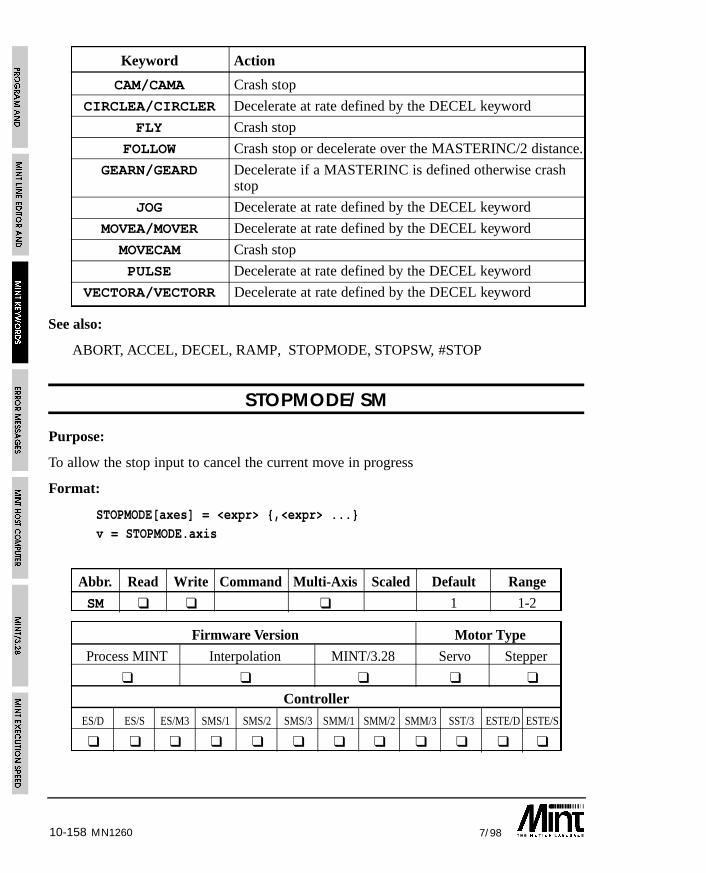
10-158 7/98MN1260
Keyword Action
CAM/CAMA Crash stop
CIRCLEA/CIRCLER Decelerate at rate defined by the DECEL keyword
FLY Crash stop
FOLLOW Crash stop or decelerate over the MASTERINC/2 distance.
GEARN/GEARD Decelerate if a MASTERINC is defined otherwise crashstop
JOG Decelerate at rate defined by the DECEL keyword
MOVEA/MOVER Decelerate at rate defined by the DECEL keyword
MOVECAM Crash stop
PULSE Decelerate at rate defined by the DECEL keyword
VECTORA/VECTORR Decelerate at rate defined by the DECEL keyword
See also:
ABORT, ACCEL, DECEL, RAMP, STOPMODE, STOPSW, #STOP
STOPMODE/SM
Purpose:
To allow the stop input to cancel the current move in progress
Format:
STOPMODE[axes] = <expr> {,<expr> ...}v = STOPMODE.axis
Abbr. Read Write Command Multi-Axis Scaled Default Range
SM ❑ ❑ ❑ 1 1-2
Firmware Version Motor Type
Process MINT Interpolation MINT/3.28 Servo Stepper
❑ ❑ ❑ ❑ ❑
Controller
ES/D ES/S ES/M3 SMS/1 SMS/2 SMS/3 SMM/1 SMM/2 SMM/3 SST/3 ESTE/D ESTE/S
❑ ❑ ❑ ❑ ❑ ❑ ❑ ❑ ❑ ❑ ❑ ❑
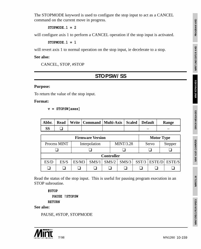
10-1597/98 MN1260
The STOPMODE keyword is used to configure the stop input to act as a CANCELcommand on the current move in progress.
STOPMODE.1 = 2
will configure axis 1 to perform a CANCEL operation if the stop input is activated.
STOPMODE.1 = 1
will revert axis 1 to normal operation on the stop input, ie decelerate to a stop.
See also:
CANCEL, STOP, #STOP
STOPSW/SS
Purpose:
To return the value of the stop input.
Format:
v = STOPSW[axes]
Abbr. Read Write Command Multi-Axis Scaled Default Range
SS ❑ – –
Firmware Version Motor Type
Process MINT Interpolation MINT/3.28 Servo Stepper
❑ ❑ ❑ ❑ ❑
Controller
ES/D ES/S ES/M3 SMS/1 SMS/2 SMS/3 SST/3 ESTE/D ESTE/S
❑ ❑ ❑ ❑ ❑ ❑ ❑ ❑ ❑
Read the status of the stop input. This is useful for pausing program execution in anSTOP subroutine.
#STOP
PAUSE !STOPSW
RETURNSee also:
PAUSE, #STOP, STOPMODE
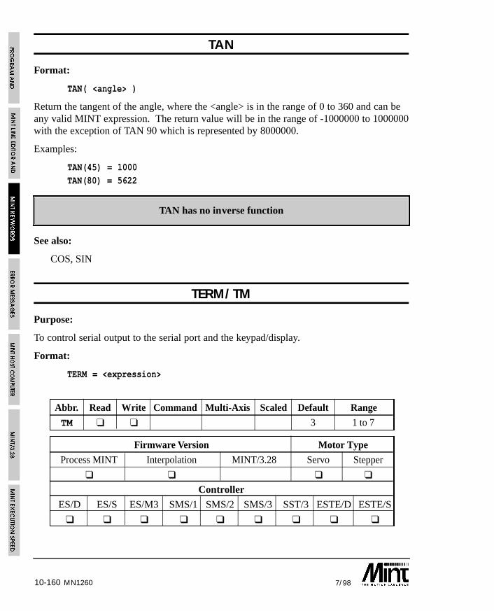
10-160 7/98MN1260
TAN
Format:
TAN( <angle> )
Return the tangent of the angle, where the <angle> is in the range of 0 to 360 and can beany valid MINT expression. The return value will be in the range of -1000000 to 1000000with the exception of TAN 90 which is represented by 8000000.
Examples:
TAN(45) = 1000TAN(80) = 5622
TAN has no inverse function
See also:
COS, SIN
TERM/TM
Purpose:
To control serial output to the serial port and the keypad/display.
Format:
TERM = <expression>
Abbr. Read Write Command Multi-Axis Scaled Default Range
TM ❑ ❑ 3 1 to 7
Firmware Version Motor Type
Process MINT Interpolation MINT/3.28 Servo Stepper
❑ ❑ ❑ ❑
Controller
ES/D ES/S ES/M3 SMS/1 SMS/2 SMS/3 SST/3 ESTE/D ESTE/S
❑ ❑ ❑ ❑ ❑ ❑ ❑ ❑ ❑
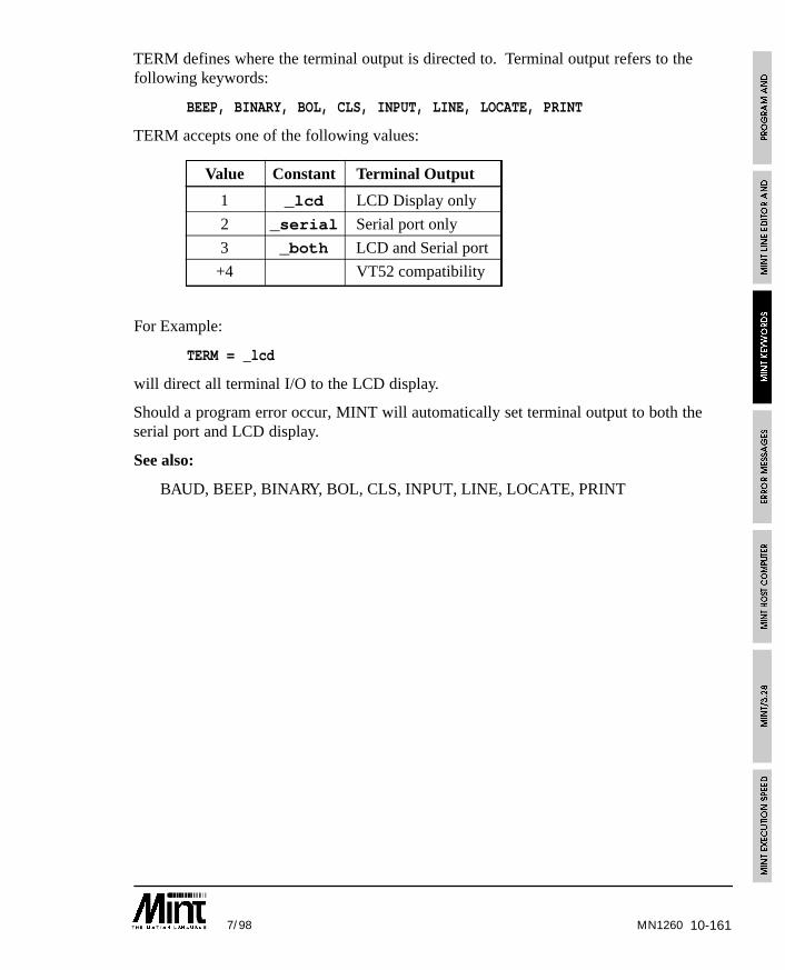
10-1617/98 MN1260
TERM defines where the terminal output is directed to. Terminal output refers to thefollowing keywords:
BEEP, BINARY, BOL, CLS, INPUT, LINE, LOCATE, PRINT
TERM accepts one of the following values:
Value Constant Terminal Output
1 _lcd LCD Display only
2 _serial Serial port only
3 _both LCD and Serial port
+4 VT52 compatibility
For Example:
TERM = _lcd
will direct all terminal I/O to the LCD display.
Should a program error occur, MINT will automatically set terminal output to both theserial port and LCD display.
See also:
BAUD, BEEP, BINARY, BOL, CLS, INPUT, LINE, LOCATE, PRINT
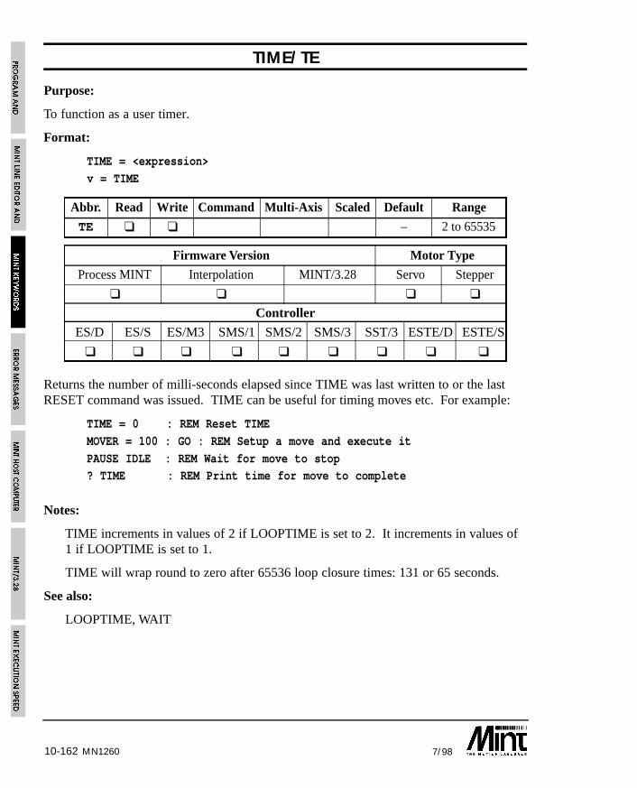
10-162 7/98MN1260
TIME/TE
Purpose:
To function as a user timer.
Format:
TIME = <expression>
v = TIME
Abbr. Read Write Command Multi-Axis Scaled Default Range
TE ❑ ❑ – 2 to 65535
Firmware Version Motor Type
Process MINT Interpolation MINT/3.28 Servo Stepper
❑ ❑ ❑ ❑
Controller
ES/D ES/S ES/M3 SMS/1 SMS/2 SMS/3 SST/3 ESTE/D ESTE/S
❑ ❑ ❑ ❑ ❑ ❑ ❑ ❑ ❑
Returns the number of milli-seconds elapsed since TIME was last written to or the lastRESET command was issued. TIME can be useful for timing moves etc. For example:
TIME = 0 : REM Reset TIME
MOVER = 100 : GO : REM Setup a move and execute it
PAUSE IDLE : REM Wait for move to stop? TIME : REM Print time for move to complete
Notes:
TIME increments in values of 2 if LOOPTIME is set to 2. It increments in values of1 if LOOPTIME is set to 1.
TIME will wrap round to zero after 65536 loop closure times: 131 or 65 seconds.
See also:
LOOPTIME, WAIT
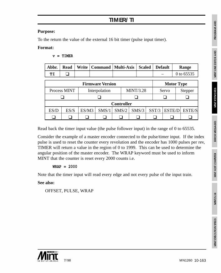
10-1637/98 MN1260
TIMER/TI
Purpose:
To the return the value of the external 16 bit timer (pulse input timer).
Format:
v = TIMER
Abbr. Read Write Command Multi-Axis Scaled Default Range
TI ❑ – 0 to 65535
Firmware Version Motor Type
Process MINT Interpolation MINT/3.28 Servo Stepper
❑ ❑ ❑ ❑ ❑
Controller
ES/D ES/S ES/M3 SMS/1 SMS/2 SMS/3 SST/3 ESTE/D ESTE/S
❑ ❑ ❑ ❑ ❑ ❑ ❑ ❑ ❑
Read back the timer input value (the pulse follower input) in the range of 0 to 65535.
Consider the example of a master encoder connected to the pulse/timer input. If the indexpulse is used to reset the counter every revolution and the encoder has 1000 pulses per rev,TIMER will return a value in the region of 0 to 1999. This can be used to determine theangular position of the master encoder. The WRAP keyword must be used to informMINT that the counter is reset every 2000 counts i.e.
WRAP = 2000
Note that the timer input will read every edge and not every pulse of the input train.
See also:
OFFSET, PULSE, WRAP
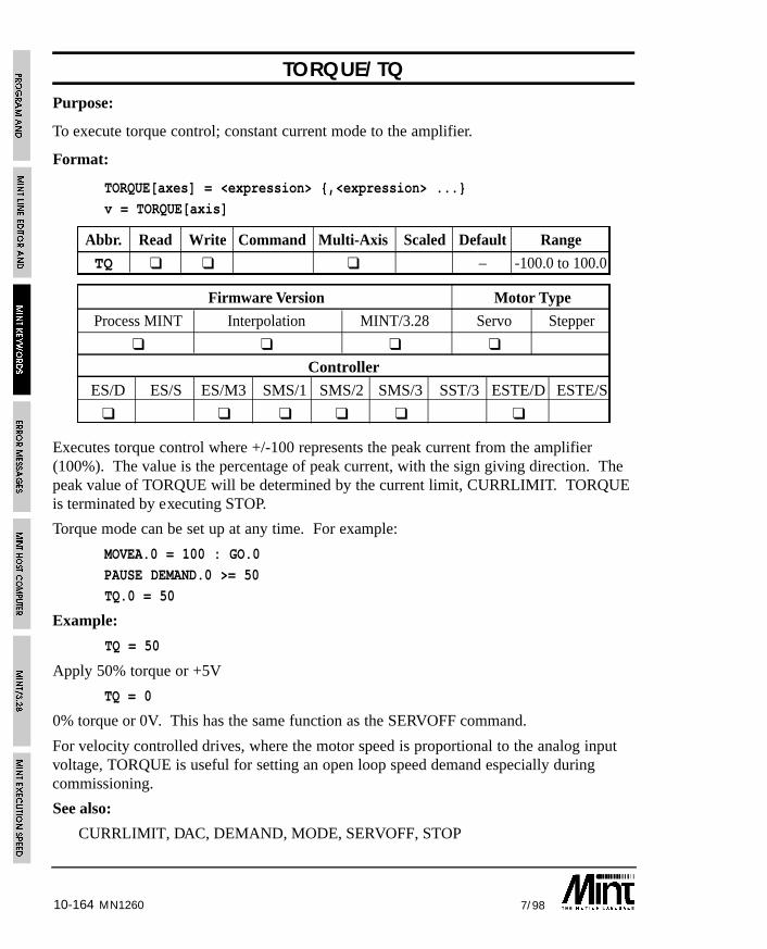
10-164 7/98MN1260
TORQUE/TQPurpose:
To execute torque control; constant current mode to the amplifier.
Format:
TORQUE[axes] = <expression> {,<expression> ...}
v = TORQUE[axis]
Abbr. Read Write Command Multi-Axis Scaled Default Range
TQ ❑ ❑ ❑ – -100.0 to 100.0
Firmware Version Motor Type
Process MINT Interpolation MINT/3.28 Servo Stepper
❑ ❑ ❑ ❑
Controller
ES/D ES/S ES/M3 SMS/1 SMS/2 SMS/3 SST/3 ESTE/D ESTE/S
❑ ❑ ❑ ❑ ❑ ❑
Executes torque control where +/-100 represents the peak current from the amplifier(100%). The value is the percentage of peak current, with the sign giving direction. Thepeak value of TORQUE will be determined by the current limit, CURRLIMIT. TORQUEis terminated by executing STOP.
Torque mode can be set up at any time. For example:
MOVEA.0 = 100 : GO.0
PAUSE DEMAND.0 >= 50
TQ.0 = 50
Example:
TQ = 50
Apply 50% torque or +5V
TQ = 0
0% torque or 0V. This has the same function as the SERVOFF command.
For velocity controlled drives, where the motor speed is proportional to the analog inputvoltage, TORQUE is useful for setting an open loop speed demand especially duringcommissioning.
See also:
CURRLIMIT, DAC, DEMAND, MODE, SERVOFF, STOP
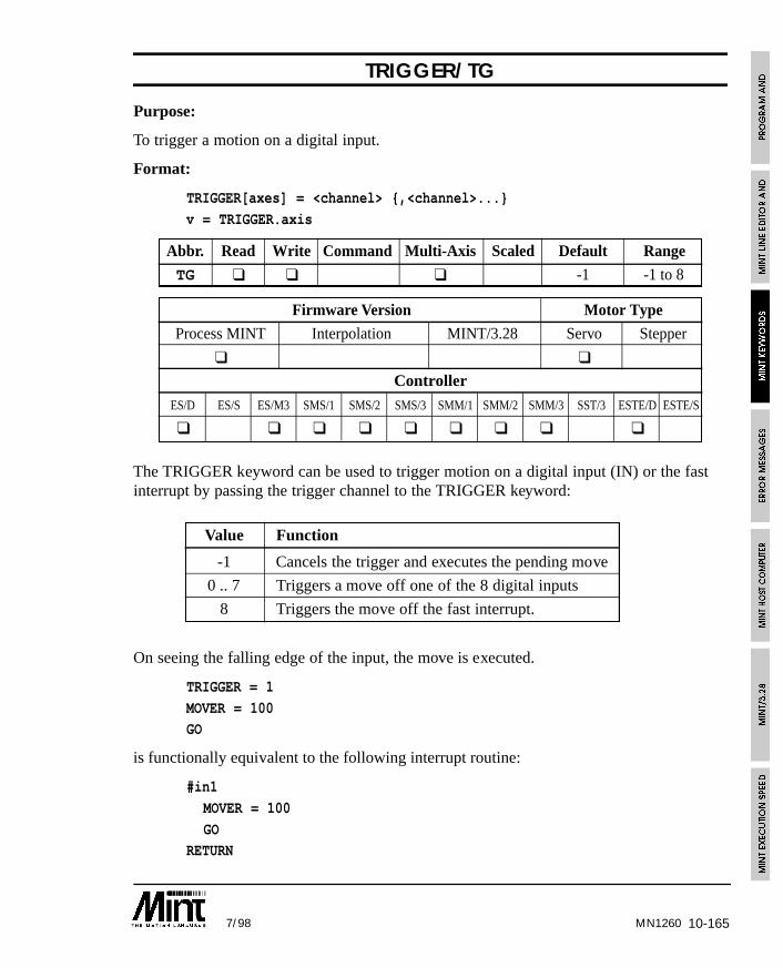
10-1657/98 MN1260
TRIGGER/TG
Purpose:
To trigger a motion on a digital input.
Format:
TRIGGER[axes] = <channel> {,<channel>...}
v = TRIGGER.axis
Abbr. Read Write Command Multi-Axis Scaled Default Range
TG ❑ ❑ ❑ -1 -1 to 8
Firmware Version Motor Type
Process MINT Interpolation MINT/3.28 Servo Stepper
❑ ❑
Controller
ES/D ES/S ES/M3 SMS/1 SMS/2 SMS/3 SMM/1 SMM/2 SMM/3 SST/3 ESTE/D ESTE/S
❑ ❑ ❑ ❑ ❑ ❑ ❑ ❑ ❑
The TRIGGER keyword can be used to trigger motion on a digital input (IN) or the fastinterrupt by passing the trigger channel to the TRIGGER keyword:
Value Function
-1 Cancels the trigger and executes the pending move
0 .. 7 Triggers a move off one of the 8 digital inputs
8 Triggers the move off the fast interrupt.
On seeing the falling edge of the input, the move is executed.
TRIGGER = 1
MOVER = 100GO
is functionally equivalent to the following interrupt routine:
#in1
MOVER = 100
GORETURN
10-166 7/98
Using the TRIGGER keyword however, guarantees that the move will begin executionwith 2ms.
The digital input channel (0 to 7) is passed to TRIGGER to specify which input starts themove. Once a move has been triggered, it must be re-triggered using the TRIGGERcommand. For example:
TRIGGER = 1
MOVER = 100GO
MOVER = 200
GO
The first GO will wait for the trigger signal, the second GO will execute immediately.
Triggering can be applied to the following move types:
• CAM, CAMA
• FLY
• FOLLOW
• GEARN/GEARD
• JOG
• MOVEA, MOVER (GO must also be executed)
• OFFSET
• PULSE
• VECTORA, VECTORR (GO must also be executed)
If a slaved move (CAM, FLY, FOLLOW, GEARN/GEARD) is triggered off the fastinterrupt where the master input is one of the 3 internal axes (FOLLOWAXIS = 0,1 or 2),the position of the master will be recorded. The recorded master position will be used tocalculate the slave position allowing for accurate registration to the fast interrupt.
The triggered move can be cleared and executed by setting TRIGGER to -1. For example:
TRIGGER = 1,1
MOVER = 100,200 :GO
TIME = 0
PAUSE TIME > 100 OR TRIGGER = 0TRIGGER = -1,-1
will trigger 2 moves on input 1. If the trigger does not come within 100 milli-seconds, themove will be triggered in software.
MN1260
10-1677/98
Reading TRIGGER will return the move type that is currently waiting for a trigger input.If no move is waiting, TRIGGER will return 0 (see MODE keyword for details of movetypes).
IMASK can be used to mask out the triggered move. IPEND can be used to clear atriggered move. See section 6.9 for more detail on TRIGGER>
Care must be taken to ensure a move has been triggered and executed beforeanother triggered move is setup. This can be tested by reading TRIGGER
which returns 0 if no moves are waiting for a trigger signal.
Special Case for FLY:
Flying shears must be treated slightly different to ensure correct motion.
MASTERINC = b
TRIGGER = 1FLY = 4096 : GO
PAUSE !TRIGGER : REM Wait for trigger to start
MASTERINC = b
FLY = 8192 : GO
Note the use of PAUSE !TRIGGER. Without this statement, the flying shear will not betriggered correctly.
See also:
INx, #INx, IMASK, IPEND
TROFF
Purpose:
To turn program trace off.
Format:
TROFF
Trace program execution off. See TRON for details of tracing program execution.
See also:
TRON
MN1260
10-168 7/98
TRON
Purpose:
To turn program trace on.
Format:
TRON
Trace program execution on. To aid program debugging, TRON will print each linenumber of the program as it is executed. The line numbers are enclosed in squarebrackets, prefixed by ‘C’ for the configuration file and ‘P’ for the program file. TRON andTROFF can be used within a program.
Example:
TRONFOR a = 1 to 5
PRINT a
NEXT
TROFF
On execution the following will be displayed:
[C 1]
[P 1] [P 2] [P 3] 1[P 4] [P 3] 2
[P 4] [P 3] 3
[P 4] [P 3] 4
[P 4] [P 3] 5
[P 5][P 6]
Using cTERM for DOS, the displayed output can be saved to a file for later inspection.Press F4 to save, select “other” and enter the filename. All displayed output will be savedto file. Press Esc to save the file. The file can now be inspected using an editor.
See also:
TROFF
MN1260
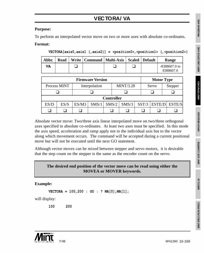
10-1697/98 MN1260
VECTORA/VA
Purpose:
To perform an interpolated vector move on two or more axes with absolute co-ordinates.
Format:
VECTORA[axis0,axis1 {,axis2}] = <position0>,<position1> {,<position2>}
Abbr. Read Write Command Multi-Axis Scaled Default Range
VA ❑ ❑ ❑ -8388607.0 to8388607.0
Firmware Version Motor Type
Process MINT Interpolation MINT/3.28 Servo Stepper
❑ ❑ ❑ ❑ ❑
Controller
ES/D ES/S ES/M3 SMS/1 SMS/2 SMS/3 SST/3 ESTE/D ESTE/S
❑ ❑ ❑ ❑ ❑ ❑ ❑ ❑
Absolute vector move: Two/three axis linear interpolated move on two/three orthogonalaxes specified in absolute co-ordinates. At least two axes must be specified. In this modethe axis speed, acceleration and ramp apply not to the individual axis but to the vectoralong which movement occurs. The command will be accepted during a current positionalmove but will not be executed until the next GO statement.
Although vector moves can be mixed between stepper and servo motors, it is desirablethat the step count on the stepper is the same as the encoder count on the servo.
The desired end position of the vector move can be read using either theMOVEA or MOVER keywords.
Example:
VECTORA = 100,200 : GO : ? MA[0];MA[1];
will display:
100 200
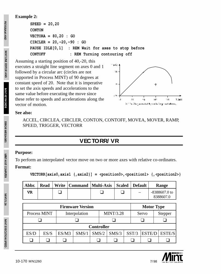
10-170 7/98MN1260
Example 2:
SPEED = 20,20
CONTON
VECTORA = 80,20 : GO
CIRCLER = 20,-20,-90 : GOPAUSE IDLE[0,1] : REM Wait for axes to stop before
CONTOFF : REM Turning contouring off
Assuming a starting position of 40,-20, thisexecutes a straight line segment on axes 0 and 1followed by a circular arc (circles are notsupported in Process MINT) of 90 degrees atconstant speed of 20. Note that it is imperativeto set the axis speeds and accelerations to thesame value before executing the move sincethese refer to speeds and accelerations along thevector of motion.
See also:
ACCEL, CIRCLEA, CIRCLER, CONTON, CONTOFF, MOVEA, MOVER, RAMP,SPEED, TRIGGER, VECTORR
VECTORR/VR
Purpose:
To perform an interpolated vector move on two or more axes with relative co-ordinates.
Format:
VECTORR[axis0,axis1 {,axis2}] = <position0>,<position1> {,<position2>}
Abbr. Read Write Command Multi-Axis Scaled Default Range
VR ❑ ❑ ❑ – -8388607.0 to8388607.0
Firmware Version Motor Type
Process MINT Interpolation MINT/3.28 Servo Stepper
❑ ❑ ❑ ❑ ❑
Controller
ES/D ES/S ES/M3 SMS/1 SMS/2 SMS/3 SST/3 ESTE/D ESTE/S
❑ ❑ ❑ ❑ ❑ ❑ ❑ ❑
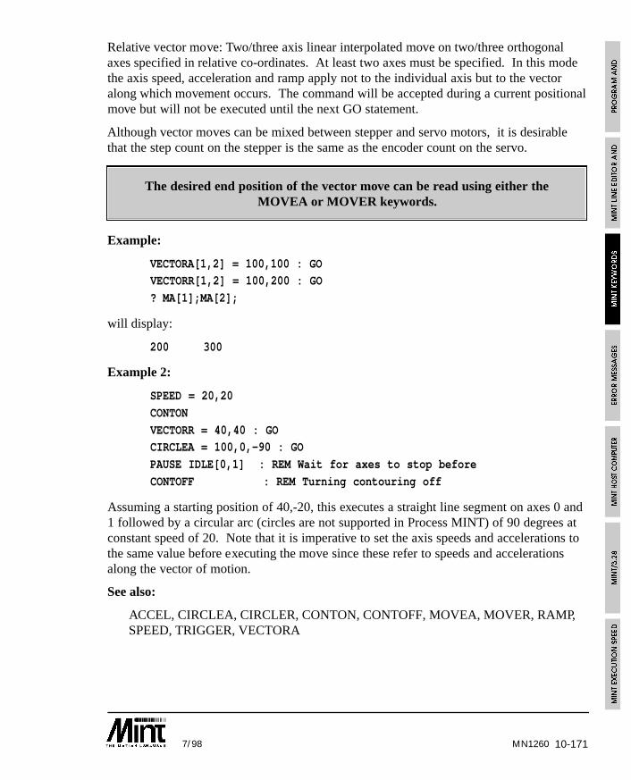
10-1717/98
Relative vector move: Two/three axis linear interpolated move on two/three orthogonalaxes specified in relative co-ordinates. At least two axes must be specified. In this modethe axis speed, acceleration and ramp apply not to the individual axis but to the vectoralong which movement occurs. The command will be accepted during a current positionalmove but will not be executed until the next GO statement.
Although vector moves can be mixed between stepper and servo motors, it is desirablethat the step count on the stepper is the same as the encoder count on the servo.
The desired end position of the vector move can be read using either theMOVEA or MOVER keywords.
Example:
VECTORA[1,2] = 100,100 : GOVECTORR[1,2] = 100,200 : GO
? MA[1];MA[2];
will display:
200 300
Example 2:
SPEED = 20,20
CONTON
VECTORR = 40,40 : GOCIRCLEA = 100,0,-90 : GO
PAUSE IDLE[0,1] : REM Wait for axes to stop before
CONTOFF : REM Turning contouring off
Assuming a starting position of 40,-20, this executes a straight line segment on axes 0 and1 followed by a circular arc (circles are not supported in Process MINT) of 90 degrees atconstant speed of 20. Note that it is imperative to set the axis speeds and accelerations tothe same value before executing the move since these refer to speeds and accelerationsalong the vector of motion.
See also:
ACCEL, CIRCLEA, CIRCLER, CONTON, CONTOFF, MOVEA, MOVER, RAMP,SPEED, TRIGGER, VECTORA
MN1260
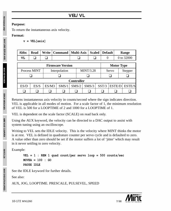
10-172 7/98MN1260
VEL/VL
Purpose:
To return the instantaneous axis velocity.
Format:
v = VEL[axis]
Abbr. Read Write Command Multi-Axis Scaled Default Range
VL ❑ ❑ ❑ ❑ 0 0 to 32000
Firmware Version Motor Type
Process MINT Interpolation MINT/3.28 Servo Stepper
❑ ❑ ❑ ❑ ❑
Controller
ES/D ES/S ES/M3 SMS/1 SMS/2 SMS/3 SST/3 ESTE/D ESTE/S
❑ ❑ ❑ ❑ ❑ ❑ ❑ ❑ ❑
Returns instantaneous axis velocity in counts/second where the sign indicates direction.VEL is applicable in all modes of motion. For a scale factor of 1, the minimum resolutionof VEL is 500 for a LOOPTIME of 2 and 1000 for a LOOPTIME of 1.
VEL is dependent on the scale factor (SCALE) on read back only.
Using the AUX keyword, the velocity can be directed to a DAC output to assist withsystem tuning using an oscilloscope.
Writing to VEL sets the IDLE velocity. This is the velocity where MINT thinks the motoris at rest. VEL is defined in quadrature counter per servo cycle and is defaulted to zero.A value other than zero should be set if the motor suffers a lot of ‘jitter’ which may resultin it never settling to zero velocity.
Example:
VEL = 1 : REM 1 quad count/per servo loop = 500 counts/sec
MOVEA = 100 : GO
PAUSE IDLE
See the IDLE keyword for further details.
See also:
AUX, JOG, LOOPTIME. PRESCALE, PULSEVEL, SPEED
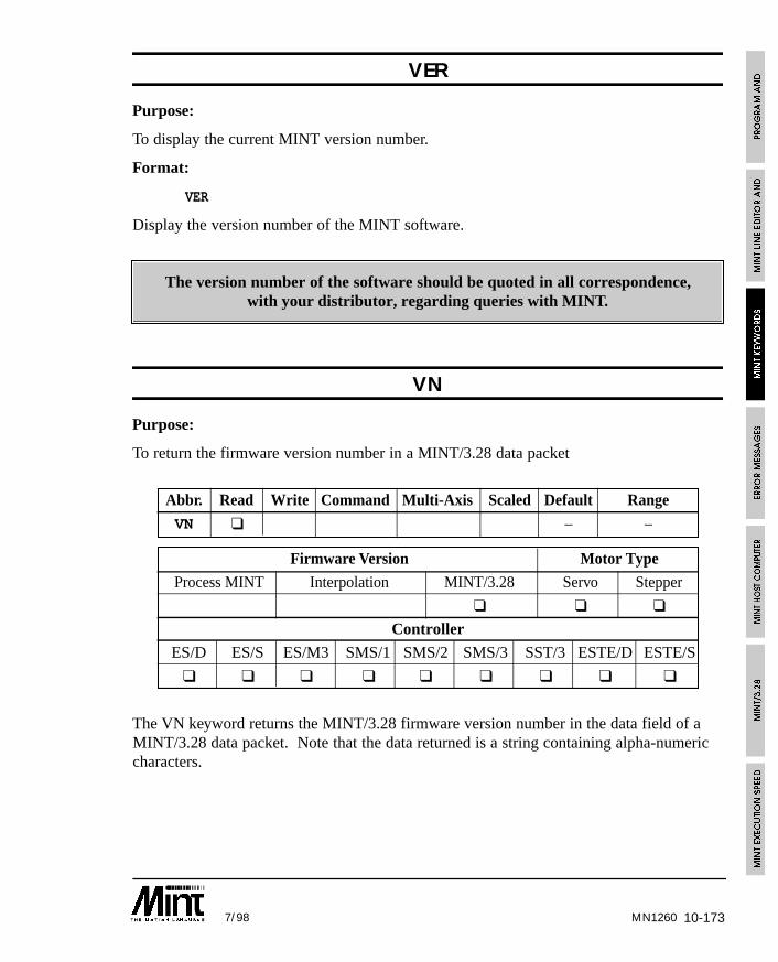
10-1737/98 MN1260
VER
Purpose:
To display the current MINT version number.
Format:
VER
Display the version number of the MINT software.
The version number of the software should be quoted in all correspondence,with your distributor, regarding queries with MINT.
VN
Purpose:
To return the firmware version number in a MINT/3.28 data packet
Abbr. Read Write Command Multi-Axis Scaled Default Range
VN ❑ – –
Firmware Version Motor Type
Process MINT Interpolation MINT/3.28 Servo Stepper
❑ ❑ ❑
Controller
ES/D ES/S ES/M3 SMS/1 SMS/2 SMS/3 SST/3 ESTE/D ESTE/S
❑ ❑ ❑ ❑ ❑ ❑ ❑ ❑ ❑
The VN keyword returns the MINT/3.28 firmware version number in the data field of aMINT/3.28 data packet. Note that the data returned is a string containing alpha-numericcharacters.
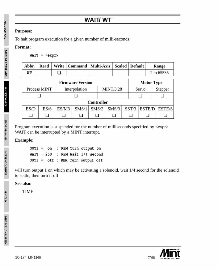
10-174 7/98MN1260
WAIT/WT
Purpose:
To halt program execution for a given number of milli-seconds.
Format:
WAIT = <expr>
Abbr. Read Write Command Multi-Axis Scaled Default Range
WT ❑ – 2 to 65535
Firmware Version Motor Type
Process MINT Interpolation MINT/3.28 Servo Stepper
❑ ❑ ❑ ❑
Controller
ES/D ES/S ES/M3 SMS/1 SMS/2 SMS/3 SST/3 ESTE/D ESTE/S
❑ ❑ ❑ ❑ ❑ ❑ ❑ ❑ ❑
Program execution is suspended for the number of milliseconds specified by <expr>.WAIT can be interrupted by a MINT interrupt.
Example:
OUT1 = _on : REM Turn output on
WAIT = 250 : REM Wait 1/4 second
OUT1 = _off : REM Turn output off
will turn output 1 on which may be activating a solenoid, wait 1/4 second for the solenoidto settle, then turn if off.
See also:
TIME
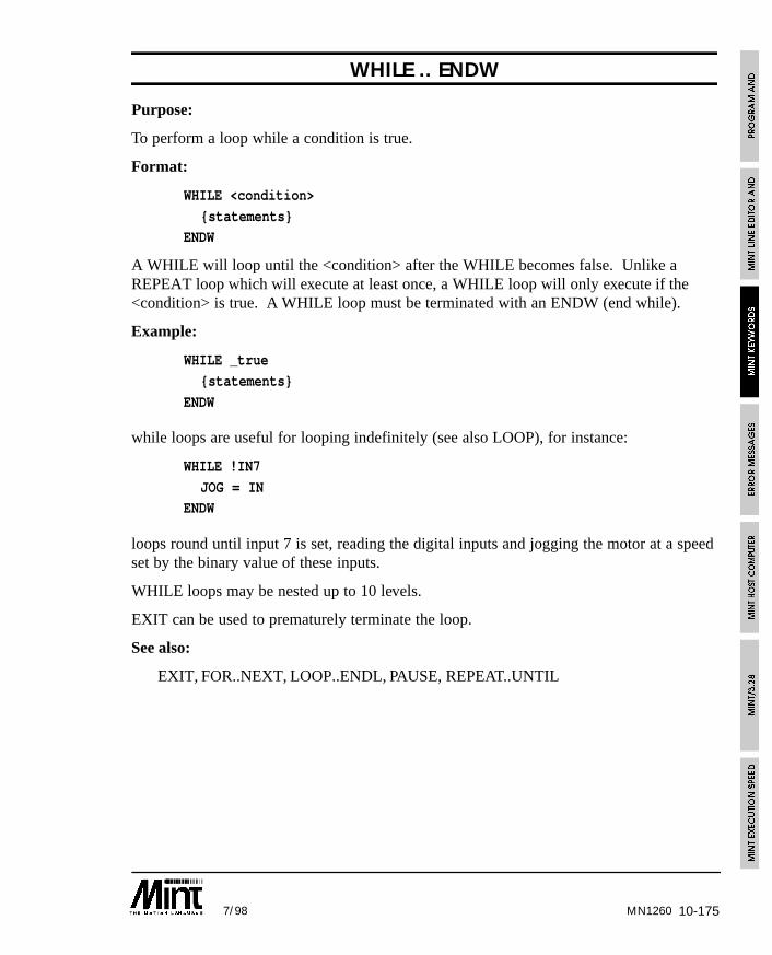
10-1757/98
WHILE .. ENDW
Purpose:
To perform a loop while a condition is true.
Format:
WHILE <condition>
{statements}ENDW
A WHILE will loop until the <condition> after the WHILE becomes false. Unlike aREPEAT loop which will execute at least once, a WHILE loop will only execute if the<condition> is true. A WHILE loop must be terminated with an ENDW (end while).
Example:
WHILE _true
{statements}
ENDW
while loops are useful for looping indefinitely (see also LOOP), for instance:
WHILE !IN7
JOG = INENDW
loops round until input 7 is set, reading the digital inputs and jogging the motor at a speedset by the binary value of these inputs.
WHILE loops may be nested up to 10 levels.
EXIT can be used to prematurely terminate the loop.
See also:
EXIT, FOR..NEXT, LOOP..ENDL, PAUSE, REPEAT..UNTIL
MN1260
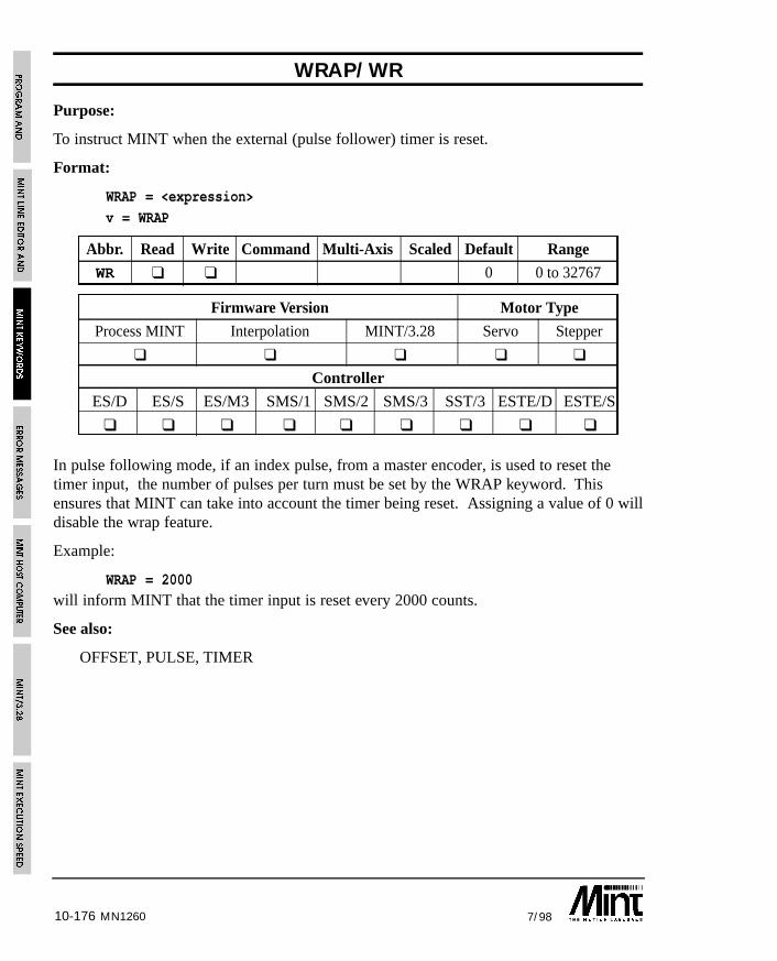
10-176 7/98MN1260
WRAP/WR
Purpose:
To instruct MINT when the external (pulse follower) timer is reset.
Format:
WRAP = <expression>
v = WRAP
Abbr. Read Write Command Multi-Axis Scaled Default Range
WR ❑ ❑ 0 0 to 32767
Firmware Version Motor Type
Process MINT Interpolation MINT/3.28 Servo Stepper
❑ ❑ ❑ ❑ ❑
Controller
ES/D ES/S ES/M3 SMS/1 SMS/2 SMS/3 SST/3 ESTE/D ESTE/S
❑ ❑ ❑ ❑ ❑ ❑ ❑ ❑ ❑
In pulse following mode, if an index pulse, from a master encoder, is used to reset thetimer input, the number of pulses per turn must be set by the WRAP keyword. Thisensures that MINT can take into account the timer being reset. Assigning a value of 0 willdisable the wrap feature.
Example:
WRAP = 2000will inform MINT that the timer input is reset every 2000 counts.
See also:
OFFSET, PULSE, TIMER

10-1777/98 MN1260
22Not standard. Cannot be used in conjunction with the 3rd Axis Servo Board (ES/06)
XENCODER/XE
Purpose:
To read back the position of the encoder on the three channel encoder interface board.
Format:
XENCODER[axes] = <expr> {,<expr> ...}
v = XENCODER[axis]
Abbr. Read Write Command Multi-Axis Scaled Default Range
XE ❑ ❑ ❑ – -8388607 to8388607
Firmware Version Motor Type
Process MINT Interpolation MINT/3.28 Servo Stepper
❑ ❑ ❑ ❑ ❑
Controller
ES/D ES/S ES/M3 SMS/1 SMS/2 SMS/3 SMM/1 SMM/2 SMM/3 SST/3 ESTE/D ESTE/S
❑22 ❑ ❑ ❑ ❑ ❑ ❑ ❑ ❑22 ❑
The operating firmware for the 3 channel encoder interface board is supported as standardwith esMINT v2.65 and above (denoted by /X on the version number) on most controllers.In order to use the XENCODER keyword, the 3 channel encoder board must be switchedon using the AXISCON keyword as follows:
AXISCON.1 = AXISCON.1 | 010
This will turn on the external encoder for axis 1. Note the use of a binary number andbitwise OR to retain bit settings on AXISCON.
The use of the XENCODER keyword has been further enhanced as follows:
The XENCODER value can be written to. This allows the 3 channel encoderinterface board to be used for positional verification on a stepper system.
The 3 channel encoder board can be used to provide a master reference to camprofiles, flying shears and software gearboxes. The source of the master input is givenusing the FOLLOWAXIS keyword:
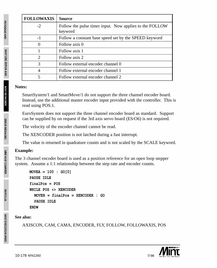
10-178 7/98MN1260
FOLLOWAXIS Source
-2 Follow the pulse timer input. Now applies to the FOLLOWkeyword
-1 Follow a constant base speed set by the SPEED keyword
0 Follow axis 0
1 Follow axis 1
2 Follow axis 2
3 Follow external encoder channel 0
4 Follow external encoder channel 1
5 Follow external encoder channel 2
Notes:
SmartSystem/1 and SmartMove/1 do not support the three channel encoder board.Instead, use the additional master encoder input provided with the controller. This isread using POS.1.
EuroSystem does not support the three channel encoder board as standard. Supportcan be supplied by on request if the 3rd axis servo board (ES/O6) is not required.
The velocity of the encoder channel cannot be read.
The XENCODER position is not latched during a fast interrupt.
The value is returned in quadrature counts and is not scaled by the SCALE keyword.
Example:
The 3 channel encoder board is used as a position reference for an open loop steppersystem. Assume a 1:1 relationship between the step rate and encoder counts.
MOVEA = 100 : GO[0]
PAUSE IDLE
finalPos = POS
WHILE POS <> XENCODERMOVER = finalPos = XENCODER : GO
PAUSE IDLE
ENDW
See also:
AXISCON, CAM, CAMA, ENCODER, FLY, FOLLOW, FOLLOWAXIS, POS
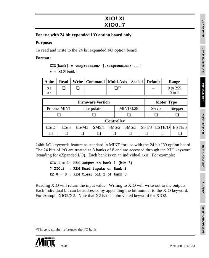
10-1797/98 MN1260
23The axis number references the I/O bank
XIO/XIXIO0..7
For use with 24 bit expanded I/O option board only
Purpose:
To read and write to the 24 bit expanded I/O option board.
Format:
XIO[bank] = <expression> {,<expression> ...}
v = XIO[bank]
Abbr. Read Write Command Multi-Axis Scaled Default Range
XI ❑ ❑ ❑ 23 – 0 to 255XX 0 to 1
Firmware Version Motor Type
Process MINT Interpolation MINT/3.28 Servo Stepper
❑ ❑ ❑ ❑ ❑
Controller
ES/D ES/S ES/M3 SMS/1 SMS/2 SMS/3 SST/3 ESTE/D ESTE/S
❑ ❑ ❑ ❑ ❑ ❑ ❑ ❑ ❑
24bit I/O keywords feature as standard in MINT for use with the 24 bit I/O option board.The 24 bits of I/O are treated as 3 banks of 8 and are accessed through the XIO keyword(standing for eXpanded I/O). Each bank is on an individual axis. For example:
XIO.1 = 1: REM Output to bank 1 (bit 8)
? XIO.2 : REM Read inputs on Bank 2
X2.0 = 0 : REM Clear bit 2 of bank 0
Reading XIO will return the input value. Writing to XIO will write out to the outputs.Each individual bit can be addressed by appending the bit number to the XIO keyword.For example XIO2/X2. Note that X2 is the abbreviated keyword for XIO2.
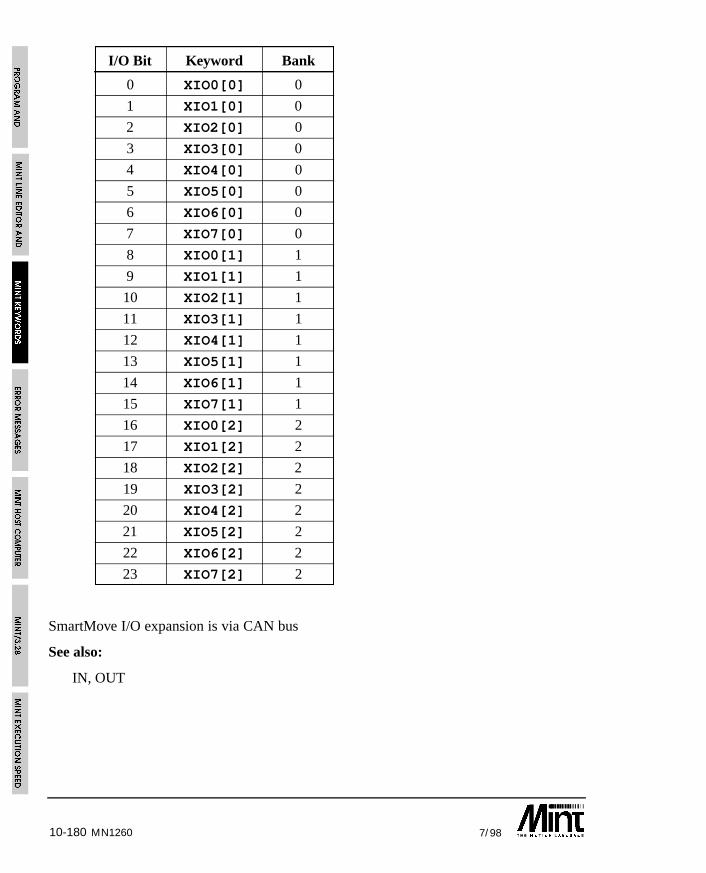
10-180 7/98MN1260
I/O Bit Keyword Bank
0 XIO0[0] 0
1 XIO1[0] 0
2 XIO2[0] 0
3 XIO3[0] 0
4 XIO4[0] 0
5 XIO5[0] 0
6 XIO6[0] 0
7 XIO7[0] 0
8 XIO0[1] 1
9 XIO1[1] 1
10 XIO2[1] 1
11 XIO3[1] 1
12 XIO4[1] 1
13 XIO5[1] 1
14 XIO6[1] 1
15 XIO7[1] 1
16 XIO0[2] 2
17 XIO1[2] 2
18 XIO2[2] 2
19 XIO3[2] 2
20 XIO4[2] 2
21 XIO5[2] 2
22 XIO6[2] 2
23 XIO7[2] 2
SmartMove I/O expansion is via CAN bus
See also:
IN, OUT
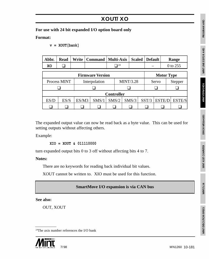
10-1817/98 MN1260
24The axis number references the I/O bank
XOUT/XO
For use with 24 bit expanded I/O option board only
Format:
v = XOUT[bank]
Abbr. Read Write Command Multi-Axis Scaled Default Range
XO ❑ ❑ 24 – 0 to 255
Firmware Version Motor Type
Process MINT Interpolation MINT/3.28 Servo Stepper
❑ ❑ ❑ ❑ ❑
Controller
ES/D ES/S ES/M3 SMS/1 SMS/2 SMS/3 SST/3 ESTE/D ESTE/S
❑ ❑ ❑ ❑ ❑ ❑ ❑ ❑ ❑
The expanded output value can now be read back as a byte value. This can be used forsetting outputs without affecting others.
Example:
XIO = XOUT & 011110000
turn expanded output bits 0 to 3 off without affecting bits 4 to 7.
Notes:
There are no keywords for reading back individual bit values.
XOUT cannot be written to. XIO must be used for this function.
SmartMove I/O expansion is via CAN bus
See also:
OUT, XOUT
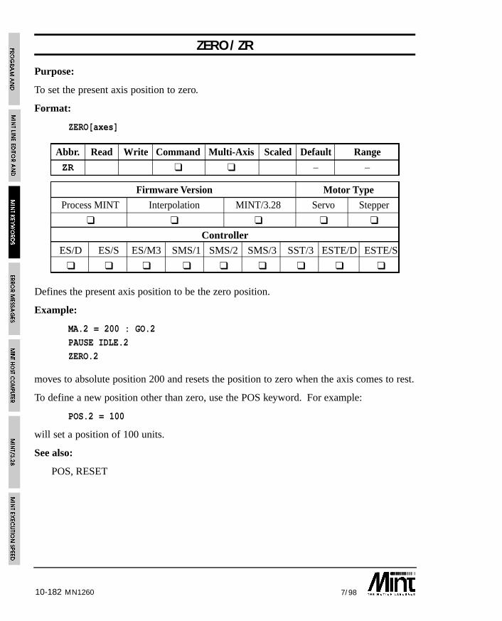
10-182 7/98MN1260
ZERO/ZR
Purpose:
To set the present axis position to zero.
Format:
ZERO[axes]
Abbr. Read Write Command Multi-Axis Scaled Default Range
ZR ❑ ❑ – –
Firmware Version Motor Type
Process MINT Interpolation MINT/3.28 Servo Stepper
❑ ❑ ❑ ❑ ❑
Controller
ES/D ES/S ES/M3 SMS/1 SMS/2 SMS/3 SST/3 ESTE/D ESTE/S
❑ ❑ ❑ ❑ ❑ ❑ ❑ ❑ ❑
Defines the present axis position to be the zero position.
Example:
MA.2 = 200 : GO.2
PAUSE IDLE.2
ZERO.2
moves to absolute position 200 and resets the position to zero when the axis comes to rest.
To define a new position other than zero, use the POS keyword. For example:
POS.2 = 100
will set a position of 100 units.
See also:
POS, RESET
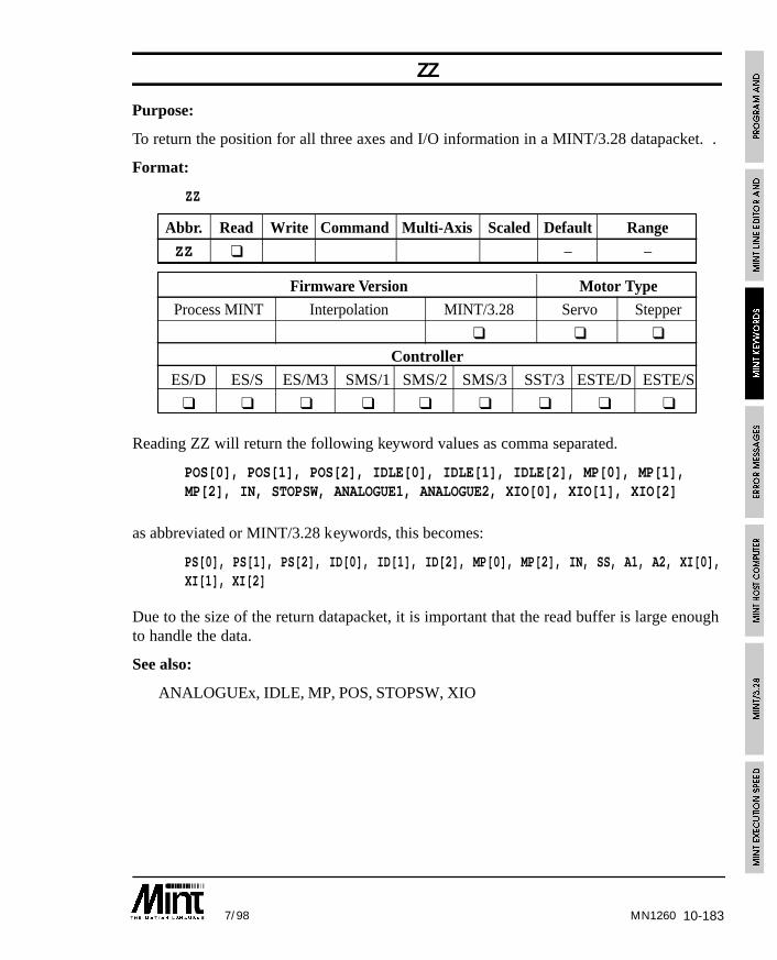
10-1837/98 MN1260
ZZ
Purpose:
To return the position for all three axes and I/O information in a MINT/3.28 datapacket. .
Format:
ZZ
Abbr. Read Write Command Multi-Axis Scaled Default Range
ZZ ❑ – –
Firmware Version Motor Type
Process MINT Interpolation MINT/3.28 Servo Stepper
❑ ❑ ❑
Controller
ES/D ES/S ES/M3 SMS/1 SMS/2 SMS/3 SST/3 ESTE/D ESTE/S
❑ ❑ ❑ ❑ ❑ ❑ ❑ ❑ ❑
Reading ZZ will return the following keyword values as comma separated.
POS[0], POS[1], POS[2], IDLE[0], IDLE[1], IDLE[2], MP[0], MP[1],MP[2], IN, STOPSW, ANALOGUE1, ANALOGUE2, XIO[0], XIO[1], XIO[2]
as abbreviated or MINT/3.28 keywords, this becomes:
PS[0], PS[1], PS[2], ID[0], ID[1], ID[2], MP[0], MP[2], IN, SS, A1, A2, XI[0],XI[1], XI[2]
Due to the size of the return datapacket, it is important that the read buffer is large enoughto handle the data.
See also:
ANALOGUEx, IDLE, MP, POS, STOPSW, XIO

10-184 7/98MN1260
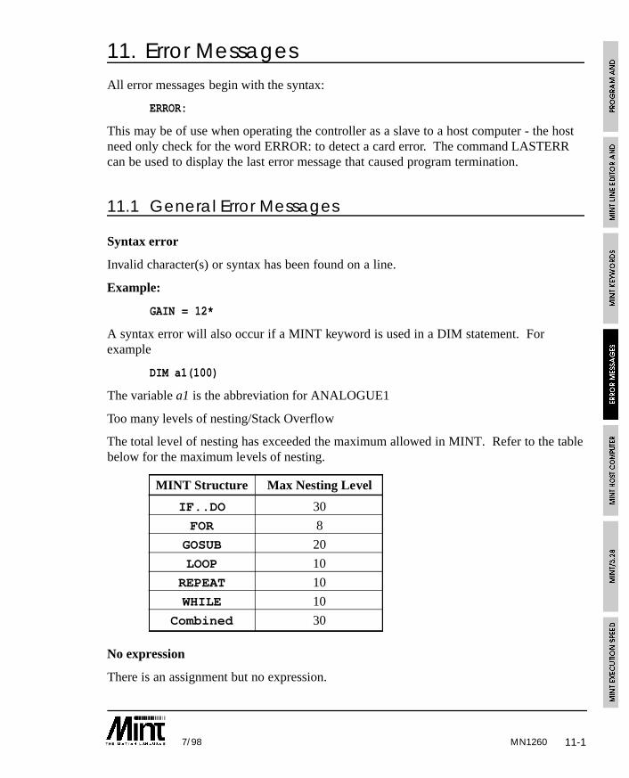
11-17/98 MN1260
11. Error MessagesAll error messages begin with the syntax:
ERROR:
This may be of use when operating the controller as a slave to a host computer - the hostneed only check for the word ERROR: to detect a card error. The command LASTERRcan be used to display the last error message that caused program termination.
11.1 General Error Messages
Syntax error
Invalid character(s) or syntax has been found on a line.
Example:
GAIN = 12*
A syntax error will also occur if a MINT keyword is used in a DIM statement. Forexample
DIM a1(100)
The variable a1 is the abbreviation for ANALOGUE1
Too many levels of nesting/Stack Overflow
The total level of nesting has exceeded the maximum allowed in MINT. Refer to the tablebelow for the maximum levels of nesting.
MINT Structure Max Nesting Level
IF..DO 30
FOR 8
GOSUB 20
LOOP 10
REPEAT 10
WHILE 10
Combined 30
No expression
There is an assignment but no expression.
11-2 7/98
Example:
avar =
Invalid Command
An unknown command is found. MINT immediately assumes it is a variable, or theprogram has encountered an ENDW or UNTIL statement without a WHILE/REPEAT.
Undefined Variables
A variable has been encountered that has not been declared or a variable has been used asa command. Use the DISPLAY command to list all the currently defined variables.
Too many variables
The total number of variables defined exceeds the total allowed (50 maximum). It may bethat variables have been declared in the immediate (user prompt) mode, that are not usedin the program. Use the RELEASE command to release all currently defined variablesfrom memory or re-define some variables.
Invalid Index
An index has been used in an array variable that is out of range. Example:
DIM a(10)
a(11) = 12 : REM Invalid index#
The index must be in the range of 1 to the maximum number of elements defined.
Out of memory
This can occur for the following reasons:
• There is not enough memory to store the compiled code.
• Too many array variables have been declared given the available memory.
• There is not enough room to insert a line of code into the current buffer.
• If you are using REM statements in your source file, remove some of them and re-execute the program. Alternatively, if arrays have been defined, reduce the number ofarray elements.
Line too long
A line within the program or configuration file exceeds 127 characters in length. Thisapplies to memory expansion and will occur during compilation.
MN1260
11-37/98
No Memory Card
An attempt was made to read or write to the memory card when no memory card exists.LOAD, SAVE and OFFLINE arrays can produce this error message. If the write protectswitch is on, a read or write from an OFFLINE array will produce a “No Memory Card”message.
11.2 Subroutine Errors
Too many labels
Too many subroutines have been defined (40 maximum).
Invalid label
This can occur for the following reasons:
• A duplicate subroutine (label) has been defined. Remember that only the first tencharacters of a name are significant, therefore “subroutine_1” and “subroutine_2” arethe same.
• A subroutine has been called that does not exist. This error will occur at compiletime.
• The label name is neither a number or a valid variable name.
RETURN w/o GOSUB
A RETURN statement has been found when no GOSUB was called.
11.3 Conditional Statement Errors
THEN or DO expected
An IF statement has been entered without a THEN or DO.
ELSE/ENDIF w/o IF DO
An ELSE or ENDIF statement has been found without an IF DO statement.
Example:
IF a = 10WHILE true
<statements>
ELSE <— Error
<statements>ENDIF
MN1260
11-4 7/98
11.4 Loop Structure Errors
TO expected
A FOR loop has been found with no TO.
NEXT w/o FOR
A NEXT has been found without a respective FOR.
ENDW w/o WHILE
An ENDW statement has been found without a respective WHILE.
UNTIL w/o REPEAT
An UNTIL statement has been found without a respective REPEAT.
Incorrect loop terminator
A loop or block structure does not have an associated closing keyword. For example,LOOP was found with no ENDL.
11.5 Motion Variable/Command Errors
Write only
An expression contains a read of a write only variable or command
Example:
a = FLY
Read only or Command
An attempt has been made to write to a read only variable or read/write to a command.Example:
A1 = 10
a = STOP
Missing parameter
A system command declaration is missing an axis in the expression.
Examples:
GAIN[1] = 10,20
VR[0,1] = ,100
In the first example, no axis number has been given for the value 20. In the secondexample, VR (vector move) requires at least 2 parameters.
MN1260
11-57/98
Card Aborted
The card is aborted when a motion keyword is executed. Use RESET or CANCEL toclear the error.
Limit Error
Limit error on axis when a motion keyword is executed. Use RESET or CANCEL toclear the error.
Following Error
Following error on axis when a motion keyword is executed. Use RESET or CANCEL toclear the error.
Invalid mode
The axis has not been set up for the correct motor type when the motion keyword isexecuted. For example:
CONFIG = _stepper
FREQ = 200
This will give an Invalid Mode error since the axis must be set-up as a servo motor beforeyou can write to the frequency generator.
Out of range
A system variable has been assigned a value that is out of its range. Remember that thevalid numerical ranges for SPEEDs, accelerations and positions vary depending on theSCALE keyword.
Motion in progress
An assignment to a motion variable or command was encountered when motion was inprogress. Some motion variables or commands can only be executed when the axis is idleor only when specific modes of motion are being used. See 11 for details of eachkeyword.
Example:
ACCEL = value
JOG = valueare both invalid during a positional move.
MN1260
11-6 7/98
Example 2:
AXES[0,1]
JOG[1] = 1000MOVEA[0] = 10 : GO
results in a motion in progress error since GO will try and begin motion on axes 0 and 1.The following will cure the problem:
AXES[0,1]
JOG[1] = 1000
MOVEA[0] = 10 : GO[0] : REM Explicit axis reference
Servo off
A move was attempted when the servo amplifier had been disabled in software with theSERVOFF command. Execute SERVON or SERVOC to turn servo power on.
Invalid axis
An axis number was specified that was not a variable or number. Array variables orexpressions cannot be used as axis numbers. Vector and circular moves require at least 2axes. An invalid axis error will occur if this is not the case.
Examples:
VR[0] = 100SF[a+1] = 1000
Output Error
Applies only to SmartMove. One or more of the digital outputs has gone into error. Thiscan be result of: over current; over temperature or short circuit. Check the wiring andclear the error using RESET.
MN1260
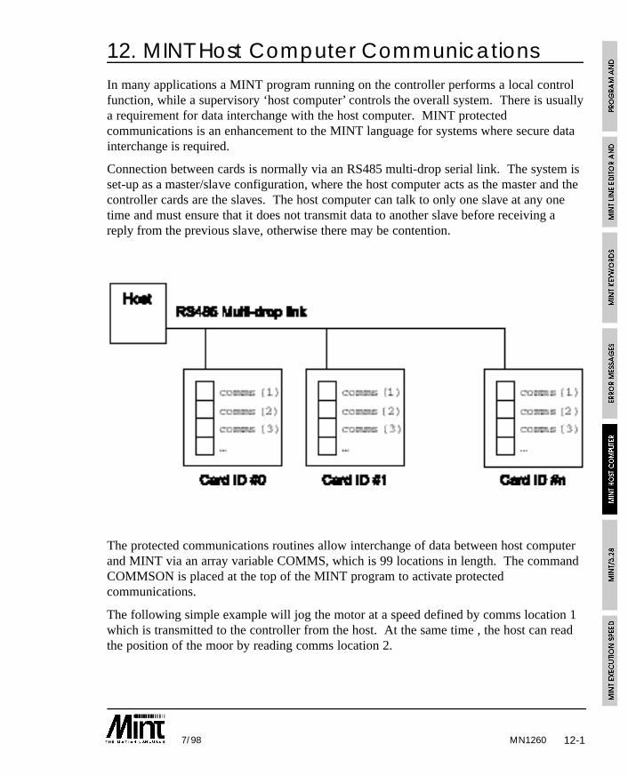
12-17/98
12. MINT Host Computer CommunicationsIn many applications a MINT program running on the controller performs a local controlfunction, while a supervisory ‘host computer’ controls the overall system. There is usuallya requirement for data interchange with the host computer. MINT protectedcommunications is an enhancement to the MINT language for systems where secure datainterchange is required.
Connection between cards is normally via an RS485 multi-drop serial link. The system isset-up as a master/slave configuration, where the host computer acts as the master and thecontroller cards are the slaves. The host computer can talk to only one slave at any onetime and must ensure that it does not transmit data to another slave before receiving areply from the previous slave, otherwise there may be contention.
The protected communications routines allow interchange of data between host computerand MINT via an array variable COMMS, which is 99 locations in length. The commandCOMMSON is placed at the top of the MINT program to activate protectedcommunications.
The following simple example will jog the motor at a speed defined by comms location 1which is transmitted to the controller from the host. At the same time , the host can readthe position of the moor by reading comms location 2.
MN1260
12-2 7/98
Example:
COMMSON
comms(1) = 0LOOP
JOG.0 = comms(1)
comms(2) = POS.0
ENDL
The protocol is based on ANSI x3.28 with minor modifications.
The end of the section gives details of some library routines for the IBM PC written inTurbo C and QBasic as supplied with MS-DOS 5.0. The routines can be found on theaccompanying diskette in the ‘comms’ directory. Alternatively, the MINT InterfaceLibrary can be purchased which provides the necessary Windows libraries for 3.1, 95 andNT, compatible with most of the common programming development tools.
12.1 Activating Protected CommunicationsThe protected protocol is activated by placing the COMMSON keyword at the top of theprogram file. This instructs MINT that all incoming data is used to make up datapackets,and as such Ctrl-E will be ignored. The communications protocol can be aborted bysending a special data packet. Ctrl-E can then be used to abort program execution.
COMMSON must be placed before any other DIM statement since it automaticallydefines the array, COMMS which is used for data transfer.
Example:
COMMSONDIM a(100)
DIM b(100)
is valid, however:
DIM a(100)DIM b(100)
COMMSON
is invalid. The array variable a, will share the same data area as the array variableCOMMS.
Ideally, COMMSON should be placed in the configuration file just after the AUTOkeyword. This reduces the chance of data packets resulting in program termination whenthe controller is powering up.
MN1260
12-37/98
Once COMMSON has been issued, MINT will now be ready to receive and process datapackets. The data packet structures are described in the following sections.
The COMMSOFF keyword is used to turn protected communications off and can be usedin conjunction with COMMSON to turn protected communications on and off. OnceCOMMSON has been used once to define the comms array, any further use will turn thecommunication protocol on.
12.2 Use of the COMMS variableCOMMS looks like an array variable of dimension 99. COMMS differs from the normalMINT array variables in that there is no need to define it with a DIM statement since it isautomatically defined with the COMMSON keyword. The contents of the COMMS arrayare preserved during power off.
Use of COMMS is very simple. For instance, consider the following wire windingapplication, where a drum is traversed between two points defined by a host computer:
COMMSONcomms(3) = 0 : REM Initialize the value first
LOOP
IF POS>COMMS(2) THEN PULSE = -COMMS(3)
IF POS<COMMS(1) THEN PULSE = COMMS(3)COMMS(4) = POS
ENDL
The program is a simple continuous loop. The drum will be driven back at forth betweenpoint specified by COMMS(2) and COMMS(1) at a speed proportional to the rotation ofthe drum (measured using an encoder on the drum). The following ratio is specified bythe variable COMMS(3). These values can be changed at any time by sending datapackets from the host computer and are automatically made available to the MINTprogram.
MN1260
12-4 7/98
Example 2:
COMMSON
comms(1) = 0LOOP
command = comms(1)
IF command <> 0 DO
IF command = 1 THEN SP.1 = comms(2):MOVEA.1 = comms(3):GO.1:PAUSE IDLE.1
IF command = 2 THEN SP.1 = comms(2):MOVER.1 = comms(3):GO.1:PAUSE IDLE.1IF command = 3 THEN HM.1 = comms(4):PAUSE IDLE.1
ENDIF
comms(1) = 0 : REM Send Ack back to host
ENDL
In this example, the host will transmit a command in comms(1). The data for the movetype is held in indexes 2 to 4. When the moves is complete, the command is set to zero.This acts as an acknowledgement to the host.
Similarly, the host can read the position of the drum by reading the value of COMMS(4),which is updated once per loop (approximately every 10mS). The communicationsroutines ensure that valid data is available to both MINT and host computer.
12.3 Read and Writing Data from a HostIn order to read from a location on a controller or write to a location, a datapacket is sentfrom the host. This is made up of ASCII characters, including control characters. In orderto send a number, this is transmitted as a string, for example “1234.5”. All controlcharacters are shown in the shaded boxes.
MN1260
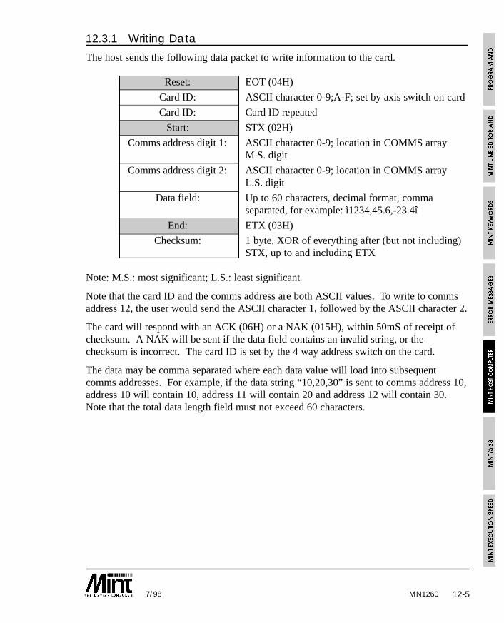
MN1260 12-57/98
12.3.1 Writing Data
The host sends the following data packet to write information to the card.
Reset: EOT (04H)
Card ID: ASCII character 0-9;A-F; set by axis switch on card
Card ID: Card ID repeated
Start: STX (02H)
Comms address digit 1: ASCII character 0-9; location in COMMS arrayM.S. digit
Comms address digit 2: ASCII character 0-9; location in COMMS arrayL.S. digit
Data field: Up to 60 characters, decimal format, commaseparated, for example: ì1234,45.6,-23.4î
End: ETX (03H)
Checksum: 1 byte, XOR of everything after (but not including)STX, up to and including ETX
Note: M.S.: most significant; L.S.: least significant
Note that the card ID and the comms address are both ASCII values. To write to commsaddress 12, the user would send the ASCII character 1, followed by the ASCII character 2.
The card will respond with an ACK (06H) or a NAK (015H), within 50mS of receipt ofchecksum. A NAK will be sent if the data field contains an invalid string, or thechecksum is incorrect. The card ID is set by the 4 way address switch on the card.
The data may be comma separated where each data value will load into subsequentcomms addresses. For example, if the data string “10,20,30” is sent to comms address 10,address 10 will contain 10, address 11 will contain 20 and address 12 will contain 30.Note that the total data length field must not exceed 60 characters.
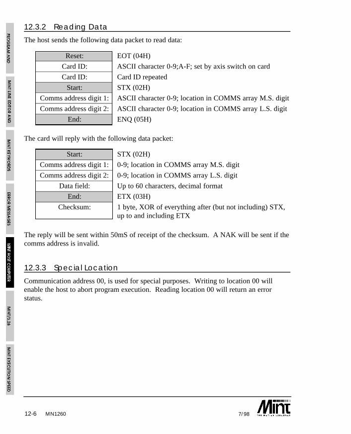
12-6 7/98
12.3.2 Reading Data
The host sends the following data packet to read data:
Reset: EOT (04H)
Card ID: ASCII character 0-9;A-F; set by axis switch on card
Card ID: Card ID repeated
Start: STX (02H)
Comms address digit 1: ASCII character 0-9; location in COMMS array M.S. digit
Comms address digit 2: ASCII character 0-9; location in COMMS array L.S. digit
End: ENQ (05H)
The card will reply with the following data packet:
Start: STX (02H)
Comms address digit 1: 0-9; location in COMMS array M.S. digit
Comms address digit 2: 0-9; location in COMMS array L.S. digit
Data field: Up to 60 characters, decimal format
End: ETX (03H)
Checksum: 1 byte, XOR of everything after (but not including) STX,up to and including ETX
The reply will be sent within 50mS of receipt of the checksum. A NAK will be sent if thecomms address is invalid.
12.3.3 Special Location
Communication address 00, is used for special purposes. Writing to location 00 willenable the host to abort program execution. Reading location 00 will return an errorstatus.
MN1260
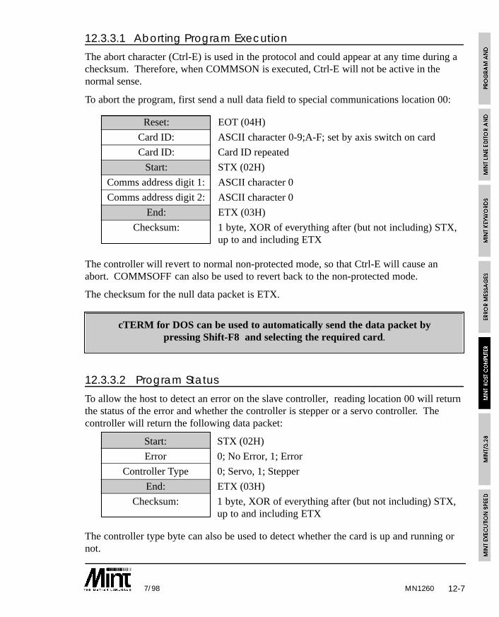
12-77/98 MN1260
12.3.3.1 Aborting Program Execution
The abort character (Ctrl-E) is used in the protocol and could appear at any time during achecksum. Therefore, when COMMSON is executed, Ctrl-E will not be active in thenormal sense.
To abort the program, first send a null data field to special communications location 00:
Reset: EOT (04H)
Card ID: ASCII character 0-9;A-F; set by axis switch on card
Card ID: Card ID repeated
Start: STX (02H)
Comms address digit 1: ASCII character 0
Comms address digit 2: ASCII character 0
End: ETX (03H)
Checksum: 1 byte, XOR of everything after (but not including) STX,up to and including ETX
The controller will revert to normal non-protected mode, so that Ctrl-E will cause anabort. COMMSOFF can also be used to revert back to the non-protected mode.
The checksum for the null data packet is ETX.
cTERM for DOS can be used to automatically send the data packet bypressing Shift-F8 and selecting the required card.
12.3.3.2 Program Status
To allow the host to detect an error on the slave controller, reading location 00 will returnthe status of the error and whether the controller is stepper or a servo controller. Thecontroller will return the following data packet:
Start: STX (02H)
Error 0; No Error, 1; Error
Controller Type 0; Servo, 1; Stepper
End: ETX (03H)
Checksum: 1 byte, XOR of everything after (but not including) STX,up to and including ETX
The controller type byte can also be used to detect whether the card is up and running ornot.
12-8 7/98
12.4 Limitations of UseINKEY and INPUT should not be used when MINT is in protected communications modesince they will take bytes from the incoming data packet, corrupting it, unless TERM isused it direction all terminal I/O to the LCD keypad and display.
12.5 PC Library RoutinesSample source code is provided with the installation disk for integration into Capplications. Alternatively, the MINT Interface Library can be purchased which providesthe necessary Windows libraries for 3.1, 95 and NT, compatible with most of the commonprogramming development tools.
Using the Host Computer Communications facility in MINT (COMMSON keyword), ahost computer can communicate with MINT over the serial port, using a protectedprotocol. Two example programs are given, one written in ‘C’ and the other written inQBasic as supplied with MS-DOS 5.0. These provide two functions which allow you tosend and receive data to and from the controller. Both programs are available on theaccompanying Applications and Utilities diskette in the following files
COMMSON.C: C Routines found in CLIB sib-directory
COMMSON.BAS QBasic Routines found in BASICLIB sub-directory
Although MINT does not support floating point numbers as such, instead using scaledintegers, floats are used within the example programs. Care must be taken that thefloating point numbers are not converted to exponent form for transmission.
12.5.1 C Interface
The C source provides the necessary routines to read and write data with the followingfeatures:
• Retry a maximum of 5 times
• Re-transmit on a checksum error
• Floating point numbers as the default data type
A serial port interface, written in Borland Turbo C, can be found on the enclosedapplications diskette in the CLIB directory. The following functions are used in theCOMMS routines to access the serial port buffer:
void flushSerialPort( void )
Flush serial port or serial port buffer
int getCharacterFromSerialPort( void )
MN1260
12-97/98
Read the next character from the serial port or serial port buffer in the range of 0 to 255.It is assumed that a time-out feature has been built into the function and the function willreturn -1 if timed out.
void serialCharacterOutput( int )
Transmit a character over the serial port.
12.5.1.1 Reading and Writing Data
Data is written to the controller through the function commsWrite, which has thefollowing prototype:
int commsWrite( int card, int index, double value );
The parameters are:
card Card address 0 to 15
index Index of comms address, 0 to 99
value Value to be written
The function will return one of the following values:
0 Time-out
1 Transmitted OK
Example:
returnValue = commsWrite( 0, 10, 10.5 )
Write 10.5 to index 10 on card 0, ie. COMMS(10) = 10.5
Data is read from the controller using the function commsRead, which has the followingprototype:
int commsRead( int card, int index, double *value );
The parameters are:
card Card address 0 to 15
index Index of comms address, 0 to 99
value Value, passed by reference, that is read
MN1260
12-10 7/98
The function will return one of the following values:
0 Time-out1 Transmitted OK
Example:
returnValue = commsRead( 1, 2, &value );
Read COMMS(2) from card 1.
The source code can be found on the enclosed applications diskette in the COMMSONdirectory.
12.5.2 MS-DOS 5.0 QBasic Interface
The Basic interface has been written using QBasic as supplied with MS-DOS 5.0. Itshould be possible to convert the program for other types of structured Basic. Theroutines have the following features:
• Retry a maximum of 5 times
• Re-transmit on a checksum error
• Interrupt driven serial port
• Addresses card 0 only, although addressing other cards is an easy amendment to thesoftware
12.5.2.1 Reading and Writing Data
Data is written to the controller using the writeData function which accepts the followingparameters:
letterBox Index of comms array, 0 to 99, to write
dataValue Value to be written
The function will return one of the following values:
0 Time-out
1 Transmitted OK
Example:
returnValue = writeData( 10, 200 )
Write 200 to COMMS(10).
MN1260
12-117/98
Data is read from the controller using the readData function which accepts the followingparameter:
letterBox Index of comms array, 0 to 99, to read
The value read from the controller is passed to the global variable dataValueReturned.
The function will return one of the following values:
0 Time-out
1 Transmitted OK
Example:
returnValue = readData( 1 )
Read comms address 1 ( COMMS(1) ).
An example of use is included in the main body of the program.
MN1260

12-12 7/98MN1260
13-17/98
13. MINT/3.28
MINT/3.28 is an ASCII based protected protocol derived from ANSI x3.28, implementinga subset of the Interpolation command set. MINT/3.28 can be used in place of MINT onstandard controller cards. It is suitable as a slave motion control system, where the slaveresponds to immediate commands from a host computer. The slave cannot execute itsown program.
The communication protocol caters for the 3 motion instruction types that MINT uses.These are:
• Write to a motion variable
• Read a motion variable
• Issue a command
All MINT keywords are limited to their two letter abbreviation. See section 13.9 for acomplete list of MINT motion keywords that are supported.
The system is set-up as a master/slave configuration, where the host computer acts as themaster, and the controller cards are the slaves. The slaves will tri-state their outputdrivers (RS485) unless they are requested to transmit information to the host computer.This implies that the host computer can talk to only one slave at any one time. It istherefore up to the master to ensure that it does not transmit data to another slave beforereceiving a reply from the previous slave, otherwise there may be contention on the line.
‘C’ library routines, for use on a PC, have been provided and can be found on theaccompanying Applications and Utilities diskette in the MINT328 directory. These shouldprovide an adequate interface to MINT/3.28.
13.1 Serial Port ConfigurationThe serial port is configured for:
• 9600 Baud
• 8 data bits
• no parity
• 1 stop bit
A typical system consists of a number of controller cards communicating with a hostcomputer over a multi-drop full duplex RS485 link, in a master/slave arrangement. RS232may also be used where there is only one slave card.
MN1260
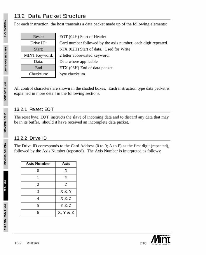
13-2 7/98MN1260
13.2 Data Packet StructureFor each instruction, the host transmits a data packet made up of the following elements:
Reset: EOT (04H) Start of Header
Drive ID: Card number followed by the axis number, each digit repeated.
Start: STX (02H) Start of data. Used for Write
MINT Keyword: 2 letter abbreviated keyword.
Data: Data where applicable
End ETX (03H) End of data packet
Checksum: byte checksum.
All control characters are shown in the shaded boxes. Each instruction type data packet isexplained in more detail in the following sections.
13.2.1 Reset: EOT
The reset byte, EOT, instructs the slave of incoming data and to discard any data that maybe in its buffer, should it have received an incomplete data packet.
13.2.2 Drive ID
The Drive ID corresponds to the Card Address (0 to 9; A to F) as the first digit (repeated),followed by the Axis Number (repeated). The Axis Number is interpreted as follows:
Axis Number Axis
0 X
1 Y
2 Z
3 X & Y
4 X & Z
5 Y & Z
6 X, Y & Z
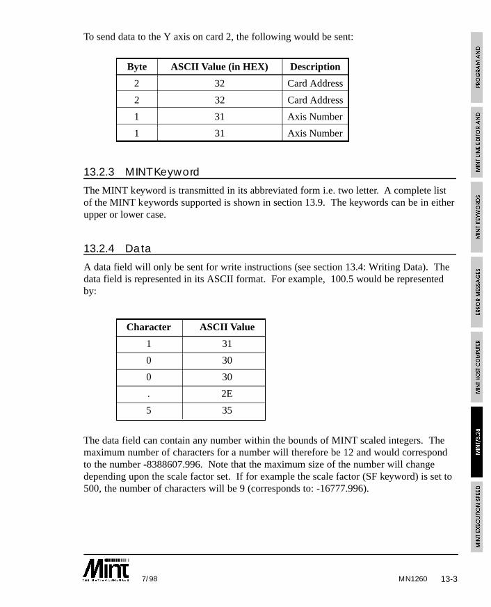
13-37/98 MN1260
To send data to the Y axis on card 2, the following would be sent:
Byte ASCII Value (in HEX) Description
2 32 Card Address
2 32 Card Address
1 31 Axis Number
1 31 Axis Number
13.2.3 MINT Keyword
The MINT keyword is transmitted in its abbreviated form i.e. two letter. A complete listof the MINT keywords supported is shown in section 13.9. The keywords can be in eitherupper or lower case.
13.2.4 Data
A data field will only be sent for write instructions (see section 13.4: Writing Data). Thedata field is represented in its ASCII format. For example, 100.5 would be representedby:
Character ASCII Value
1 31
0 30
0 30
. 2E
5 35
The data field can contain any number within the bounds of MINT scaled integers. Themaximum number of characters for a number will therefore be 12 and would correspondto the number -8388607.996. Note that the maximum size of the number will changedepending upon the scale factor set. If for example the scale factor (SF keyword) is set to500, the number of characters will be 9 (corresponds to: -16777.996).
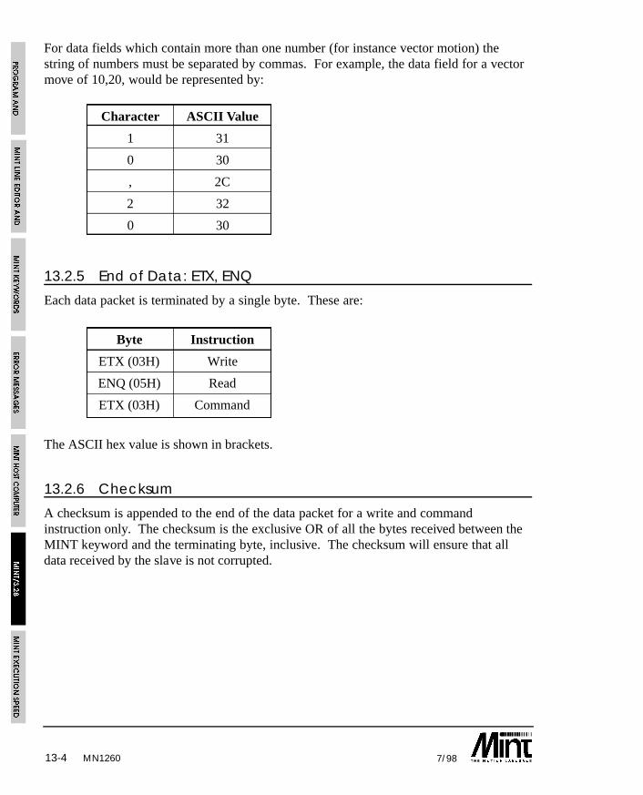
13-4 7/98MN1260
For data fields which contain more than one number (for instance vector motion) thestring of numbers must be separated by commas. For example, the data field for a vectormove of 10,20, would be represented by:
Character ASCII Value
1 31
0 30
, 2C
2 32
0 30
13.2.5 End of Data: ETX, ENQ
Each data packet is terminated by a single byte. These are:
Byte Instruction
ETX (03H) Write
ENQ (05H) Read
ETX (03H) Command
The ASCII hex value is shown in brackets.
13.2.6 Checksum
A checksum is appended to the end of the data packet for a write and commandinstruction only. The checksum is the exclusive OR of all the bytes received between theMINT keyword and the terminating byte, inclusive. The checksum will ensure that alldata received by the slave is not corrupted.
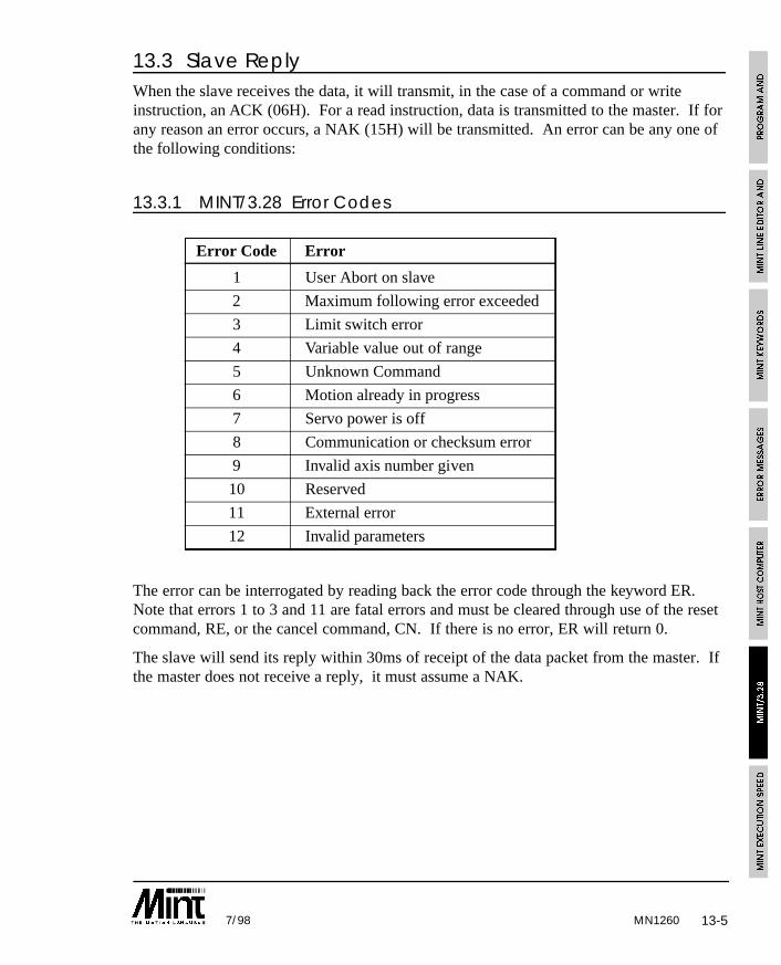
13-57/98 MN1260
13.3 Slave ReplyWhen the slave receives the data, it will transmit, in the case of a command or writeinstruction, an ACK (06H). For a read instruction, data is transmitted to the master. If forany reason an error occurs, a NAK (15H) will be transmitted. An error can be any one ofthe following conditions:
13.3.1 MINT/3.28 Error Codes
Error Code Error
1 User Abort on slave
2 Maximum following error exceeded
3 Limit switch error
4 Variable value out of range
5 Unknown Command
6 Motion already in progress
7 Servo power is off
8 Communication or checksum error
9 Invalid axis number given
10 Reserved
11 External error
12 Invalid parameters
The error can be interrogated by reading back the error code through the keyword ER.Note that errors 1 to 3 and 11 are fatal errors and must be cleared through use of the resetcommand, RE, or the cancel command, CN. If there is no error, ER will return 0.
The slave will send its reply within 30ms of receipt of the data packet from the master. Ifthe master does not receive a reply, it must assume a NAK.
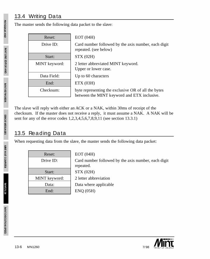
13-6 7/98MN1260
13.4 Writing DataThe master sends the following data packet to the slave:
Reset: EOT (04H)
Drive ID: Card number followed by the axis number, each digitrepeated. (see below)
Start: STX (02H)
MINT keyword: 2 letter abbreviated MINT keyword.Upper or lower case.
Data Field: Up to 60 characters
End: ETX (03H)
Checksum: byte representing the exclusive OR of all the bytesbetween the MINT keyword and ETX inclusive.
The slave will reply with either an ACK or a NAK, within 30ms of receipt of thechecksum. If the master does not receive a reply, it must assume a NAK. A NAK will besent for any of the error codes 1,2,3,4,5,6,7,8,9,11 (see section 13.3.1)
13.5 Reading DataWhen requesting data from the slave, the master sends the following data packet:
Reset: EOT (04H)
Drive ID: Card number followed by the axis number, each digitrepeated.
Start: STX (02H)
MINT keyword: 2 letter abbreviation
Data: Data where applicable
End: ENQ (05H)
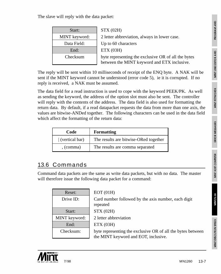
13-77/98 MN1260
The slave will reply with the data packet:
Start: STX (02H)
MINT keyword: 2 letter abbreviation, always in lower case.
Data Field: Up to 60 characters
End: ETX (03H)
Checksum byte representing the exclusive OR of all the bytesbetween the MINT keyword and ETX inclusive.
The reply will be sent within 10 milliseconds of receipt of the ENQ byte. A NAK will besent if the MINT keyword cannot be understood (error code 5), ie it is corrupted. If noreply is received, a NAK must be assumed.
The data field for a read instruction is used to cope with the keyword PEEK/PK. As wellas sending the keyword, the address of the option slot must also be sent. The controllerwill reply with the contents of the address. The data field is also used for formatting thereturn data. By default, if a read datapacket requests the data from more than one axis, thevalues are bitwise-ANDed together. The following characters can be used in the data fieldwhich affect the formatting of the return data:
Code Formatting
| (vertical bar) The results are bitwise-ORed together
, (comma) The results are comma separated
13.6 CommandsCommand data packets are the same as write data packets, but with no data. The masterwill therefore issue the following data packet for a command:
Reset: EOT (01H)
Drive ID: Card number followed by the axis number, each digitrepeated
Start: STX (02H)
MINT keyword: 2 letter abbreviation
End: ETX (03H)
Checksum: byte representing the exclusive OR of all the bytes betweenthe MINT keyword and EOT, inclusive.
13-8 7/98
The slave will reply with either an ACK or a NAK. The reply will be sent within 10milliseconds of receipt of the checksum. A NAK will be sent for the error codes1,2,3,5,6,7,8,9,11 (see section 13.3.1).
13.7 Buffered Motion CommandsMINT/3.28 will accept and set-up the next motion command when a move is in progress.This is particularly useful for contouring, or where two moves must be executed in rapidsuccession. For example:
VR 10,20
VR 12,21
Any further move instructions cannot be accepted until the first move to position 10,20 iscompleted. If any move instruction is received, the slave will reply with a NAK. Readingthe error keyword will return the error code for “motion in progress”.
During contoured motion, it is important to ensure that the next move is always in theslave’s buffer. Therefore the host must periodically check the move pending flag (MP)and immediately send the next move when it is cleared.
It is however acceptable to communicate with the slave while contoured moves are inprogress. A typical function is interrogating position to update an operator display.
13.7.1 The GO Command
The GO command is not required when a move is setup since this will be handledautomatically. When the previous move is complete, the new move will be executed.
MN1260
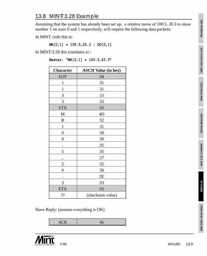
13-97/98 MN1260
13.8 MINT/3.28 ExampleAssuming that the system has already been set up, a relative move of 100.5, 20.3 to slavenumber 1 on axes 0 and 1 respectively, will require the following data packets:
In MINT code this is:
MR[0,1] = 100.5,20.3 : GO[0,1]
In MINT/3.28 this translates to :
Master: “MR[0,1] = 100.5,20.3”
Character ASCII Value (in hex)
EOT 04
1 31
1 31
3 33
3 33
STX 02
M 4D
R 52
1 31
0 30
0 30
. 2E
5 35
, 27
2 32
0 30
. 2E
3 33
ETX 03
?? (checksum value)
Slave Reply: (assume everything is OK)
ACK 06
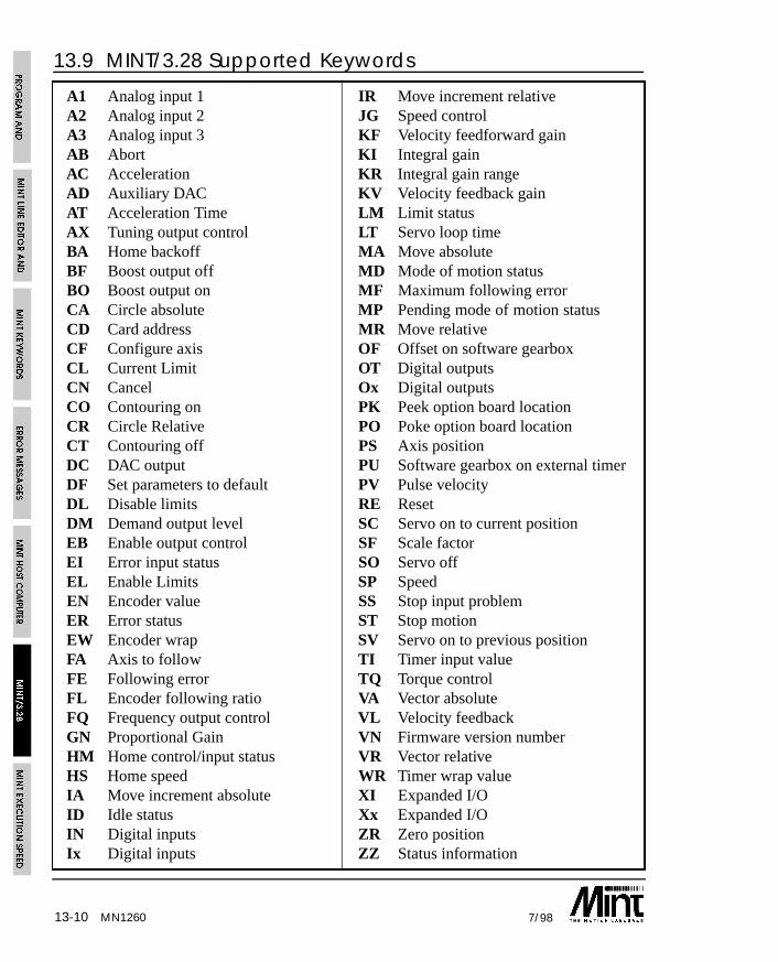
MN126013-10 7/98
A1 Analog input 1 IR Move increment relativeA2 Analog input 2 JG Speed controlA3 Analog input 3 KF Velocity feedforward gainAB Abort KI Integral gainAC Acceleration KR Integral gain rangeAD Auxiliary DAC KV Velocity feedback gainAT Acceleration Time LM Limit statusAX Tuning output control LT Servo loop timeBA Home backoff MA Move absoluteBF Boost output off MD Mode of motion statusBO Boost output on MF Maximum following errorCA Circle absolute MP Pending mode of motion statusCD Card address MR Move relativeCF Configure axis OF Offset on software gearboxCL Current Limit OT Digital outputsCN Cancel Ox Digital outputsCO Contouring on PK Peek option board locationCR Circle Relative PO Poke option board locationCT Contouring off PS Axis positionDC DAC output PU Software gearbox on external timerDF Set parameters to default PV Pulse velocityDL Disable limits RE ResetDM Demand output level SC Servo on to current positionEB Enable output control SF Scale factorEI Error input status SO Servo offEL Enable Limits SP SpeedEN Encoder value SS Stop input problemER Error status ST Stop motionEW Encoder wrap SV Servo on to previous positionFA Axis to follow TI Timer input valueFE Following error TQ Torque controlFL Encoder following ratio VA Vector absoluteFQ Frequency output control VL Velocity feedbackGN Proportional Gain VN Firmware version numberHM Home control/input status VR Vector relativeHS Home speed WR Timer wrap valueIA Move increment absolute XI Expanded I/OID Idle status Xx Expanded I/OIN Digital inputs ZR Zero positionIx Digital inputs ZZ Status information
13.9 MINT/3.28 Supported Keywords
13-117/98
13.10 MINT/3.28 C Library Routine for Host ComputerSample source code is provided with the installation disk for integration into Capplications. Alternatively, the MINT Interface Library can be purchased which providesthe necessary Windows libraries for 3.1, 95 and NT, compatible with most of the commonprogramming development tools.
The sample code gives the following functions:
• Writing to a motion variable
• Reading a motion variable
• Issuing a command
The routines have the following features:
• Retry a maximum of 5 times
• Re-transmit on a checksum error
• Floating point numbers as the default data type
The source code is available on the enclosed applications diskette in the directory CLIB(filename MINT328.c). A serial port interface, written in Borland Turbo C, can be foundon the enclosed applications diskette in the SERIAL directory. The following functionsare used in the MINT/3.28 routines to access the serial port buffer:
int getccb( void )
Read the next character from the serial port or serial port buffer in the range of 0 to 255.If no byte is available, getccb must return -1.
void SerialOut( char )
Transmit a character over the serial port.
13.10.1 Writing Data
A motion variable is written to using the function MINT328Write which has the followingprototype:
int MINT328Write( char *cardAxis, char *keyword, char *dataValue );
The parameters are:
cardAxis Card address 0 to 15, followed by axis
keyword Abbreviated keyword
value Value to be written (string)
MN1260
13-12 7/98
The functions can be easily re-written to accept floating point numbers etc.
The function will return one of the following values:
6 (ACK) OK
21 (NAK) Transmission Problem
-1 Timeout
Example:
returnValue = MINT328Write( “0011”, “SF”, “1000” );
Set the scale factor on card 0, axis 1 to 1000.
13.10.2 Reading Data
A motion variable is read using the MINT328Read function which has the followingprototype:
int MINT328Read( char *cardAxis, char *keyword, long *dataValue );
The parameters are:
cardAxis Card address 0 to 15, followed by axis
keyword Abbreviated keyword
value Value to be read, passed by reference as a long.
The function will return one of the following values:
6 (ACK) OK
21 (NAK) Transmission Problem
-1 Timeout
Example:
returnValue = MINT328Read( “1100”, “PS”, &value );
Read the position of axis 0 on card 1. The value will be returned as a scaled integer (seesection 4 for further details on scaled integers).
MN1260
13-137/98
13.10.3 Issuing a Command
A command is issued using the MINT328Command function which has the followingprototype:
int MINT328Command( char *cardAxis, char *keyword );
The parameters are:
cardAxis Card address 0 to 15, followed by axis
keyword Abbreviated keyword
The function will return one of the following values:
6 (ACK) OK
21 (NAK) Transmission Problem
-1 Timeout
Example:
returnValue = MINT328Command( “0066”, “AB” );
Abort all 3 axes on card 0.
MN1260

13-14 7/98MN1260
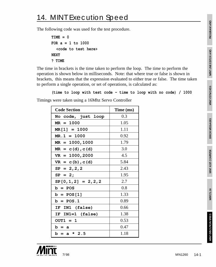
14-17/98 MN1260
14. MINT Execution SpeedThe following code was used for the test procedure.
TIME = 0
FOR a = 1 to 1000
<code to test here>
NEXT
? TIME
The time in brackets is the time taken to perform the loop. The time to perform theoperation is shown below in milliseconds. Note: that where true or false is shown inbrackets, this means that the expression evaluated to either true or false. The time takento perform a single operation, or set of operations, is calculated as:
(time to loop with test code - time to loop with no code) / 1000
Timings were taken using a 16Mhz Servo Controller
Code Section Time (ms)
No code, just loop 0.3
MR = 1000 1.05
MR[1] = 1000 1.11
MR.1 = 1000 0.92
MR = 1000,1000 1.79
MR = c(d),c(d) 3.0
VR = 1000,2000 4.5
VR = c(b),c(d) 5.84
SP = 2,2,2 2.43
SP = 2; 1.95
SP[0,1,2] = 2,2,2 2.7
b = POS 0.8
b = POS[1] 1.33
b = POS.1 0.89
IF IN1 (false) 0.66
IF IN1=1 (false) 1.38
OUT1 = 1 0.53
b = a 0.47
b = a * 2.5 1.18
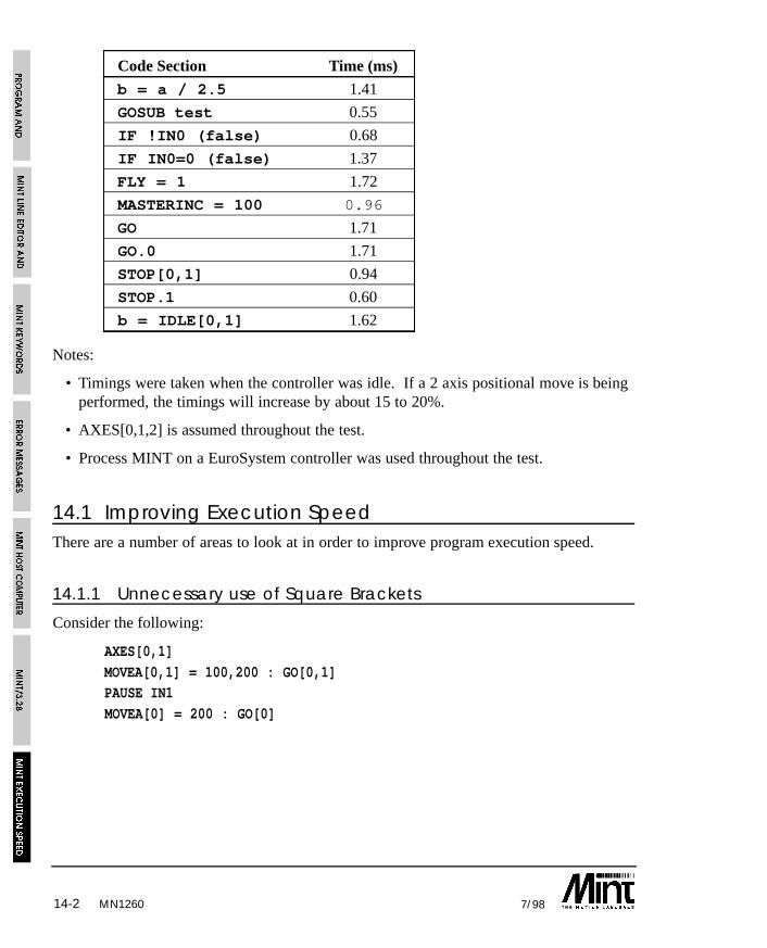
14-2 7/98MN1260
Code Section Time (ms)
b = a / 2.5 1.41
GOSUB test 0.55
IF !IN0 (false) 0.68
IF IN0=0 (false) 1.37
FLY = 1 1.72
MASTERINC = 100 0.96
GO 1.71
GO.0 1.71
STOP[0,1] 0.94
STOP.1 0.60
b = IDLE[0,1] 1.62
Notes:
• Timings were taken when the controller was idle. If a 2 axis positional move is beingperformed, the timings will increase by about 15 to 20%.
• AXES[0,1,2] is assumed throughout the test.
• Process MINT on a EuroSystem controller was used throughout the test.
14.1 Improving Execution SpeedThere are a number of areas to look at in order to improve program execution speed.
14.1.1 Unnecessary use of Square Brackets
Consider the following:
AXES[0,1]
MOVEA[0,1] = 100,200 : GO[0,1]PAUSE IN1
MOVEA[0] = 200 : GO[0]

14-37/98 MN1260
MINT will already assume that axes 0,1 exist by definition of the AXES command at thetop of the program. The program can be replaced by:
AXES[0,1]
MOVEA = 100,200 : GOPAUSE IN1
MOVEA = 200 : GO[0]
14.1.2 Optimizing Logical Expressions
In MINT, if an expression evaluates to 0, it is considered false. Any non-zero evaluatedexpressions are considered true. The following logical expressions can be optimized:
IF IN1 = 1 THEN a = 1
can become:
IF IN1 THEN a = 1
IF IN0 = 0 THEN b = 2
can become:
IF !IN0 THEN b = 2
Both of these expressions will evaluate some 10-20% quicker.
IF IN0 = 1 OR IN1 = 1 THEN c = 3
can become:
IF IN AND 011 THEN c = 3
Care must be taken when using the AND and OR keywords since AND and OR (plus theirabbreviated counterparts, & and |) are bitwise operators. Therefore:
IF (IN & 4) AND (IN & 8) THEN OUT1 = 1
will always evaluate to false. The expression must be changed to:
IF (IN AND 12) = 12
14-4 7/98MN1260
14.1.3 Removing Blank Lines
Although MINT is semi-compiled, blank lines are still interpreted allowing MINT tomaintain line numbers in case of an error. Removing blank lines can go some to helpincreasing program execution. Note that the SQUASH utility is useful for this function.
14.1.4 Performing More Time Intensive Code Outside to Dead Time
Often MINT can be left waiting for an input after which it must perform a series ofinstructions with a certain time. Consider the following:
LOOP
PAUSE IN1PAUSE !IN1 : REM Wait for falling edge
MOVER = length * factor : REM Perform an index operation
GO
ENDL
It is required that on seeing the input, the machine starts moving as quickly as possible.This can be achieved as follows:
LOOP
MOVER = length * factor : REM Setup the move
PAUSE IN1PAUSE !IN1 : REM Wait for falling edge
GO : REM Tell move to GO
ENDL
As can be seen, the move is setup in the deadtime of the loop. The move should beginsome 4-6ms quicker.
14-57/98 MN1260
14.1.5 Turning Redundant Axes Off
In a 2 axes servo system using EuroSystem, the third axes of stepper is still performingsome background calculations. By turning this axis off, program execution speed shouldincrease by about 10%. An axis can be turned off by using the CONFIG keyword:
CONFIG[2] = _off
will turn axis 2 off.
14.1.6 Replacing Single Axis Reference with Dot
A single axis reference using square brackets can be replaced with the dot syntax. Forexample:
IF POS[1] > 1000 THEN OUT1 = 1
can be replaced by:
IF POS.1 > 1000 THEN OUT1 = 1
this not only saves on code space but is about 20% quicker to execute.
SQUASH can be used to replace all single axis reference with the dot syntax.

14-6 7/98MN1260
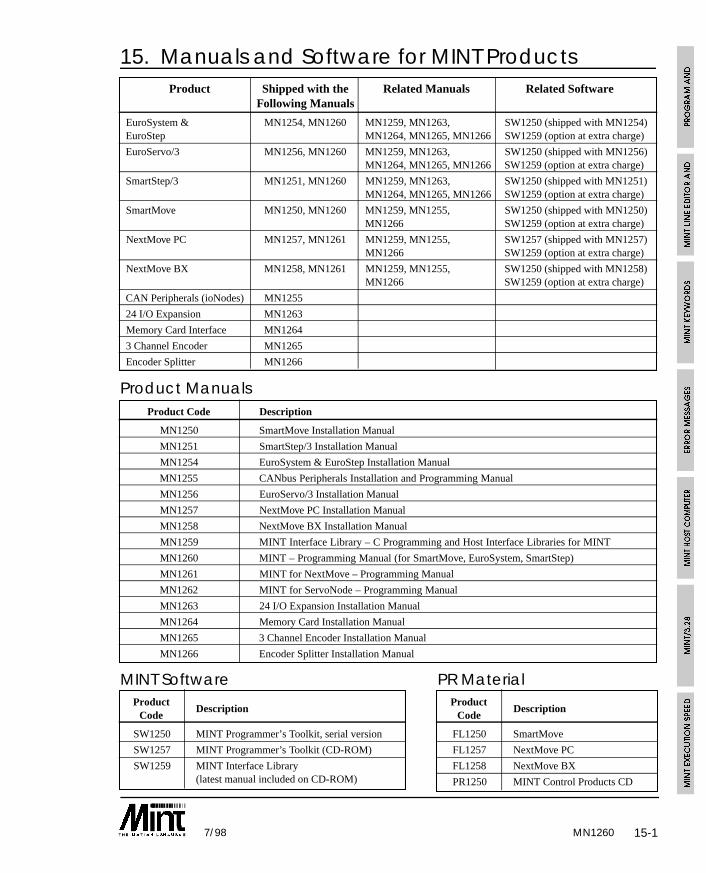
15-17/98 MN1260
15. Manuals and Software for MINT ProductsProduct Shipped with the Related Manuals Related Software
Following Manuals
EuroSystem & MN1254, MN1260 MN1259, MN1263, SW1250 (shipped with MN1254)EuroStep MN1264, MN1265, MN1266 SW1259 (option at extra charge)
EuroServo/3 MN1256, MN1260 MN1259, MN1263, SW1250 (shipped with MN1256)MN1264, MN1265, MN1266 SW1259 (option at extra charge)
SmartStep/3 MN1251, MN1260 MN1259, MN1263, SW1250 (shipped with MN1251)MN1264, MN1265, MN1266 SW1259 (option at extra charge)
SmartMove MN1250, MN1260 MN1259, MN1255, SW1250 (shipped with MN1250)MN1266 SW1259 (option at extra charge)
NextMove PC MN1257, MN1261 MN1259, MN1255, SW1257 (shipped with MN1257)MN1266 SW1259 (option at extra charge)
NextMove BX MN1258, MN1261 MN1259, MN1255, SW1250 (shipped with MN1258)MN1266 SW1259 (option at extra charge)
CAN Peripherals (ioNodes) MN1255
24 I/O Expansion MN1263
Memory Card Interface MN1264
3 Channel Encoder MN1265
Encoder Splitter MN1266
Product ManualsProduct Code Description
MN1250 SmartMove Installation Manual
MN1251 SmartStep/3 Installation Manual
MN1254 EuroSystem & EuroStep Installation Manual
MN1255 CANbus Peripherals Installation and Programming Manual
MN1256 EuroServo/3 Installation Manual
MN1257 NextMove PC Installation Manual
MN1258 NextMove BX Installation Manual
MN1259 MINT Interface Library – C Programming and Host Interface Libraries for MINT
MN1260 MINT – Programming Manual (for SmartMove, EuroSystem, SmartStep)
MN1261 MINT for NextMove – Programming Manual
MN1262 MINT for ServoNode – Programming Manual
MN1263 24 I/O Expansion Installation Manual
MN1264 Memory Card Installation Manual
MN1265 3 Channel Encoder Installation Manual
MN1266 Encoder Splitter Installation Manual
MINT SoftwareProduct
DescriptionCode
SW1250 MINT Programmer’s Toolkit, serial version
SW1257 MINT Programmer’s Toolkit (CD-ROM)
SW1259 MINT Interface Library(latest manual included on CD-ROM)
PR MaterialProduct
DescriptionCode
FL1250 SmartMove
FL1257 NextMove PC
FL1258 NextMove BX
PR1250 MINT Control Products CD

15-2 7/98MN1260
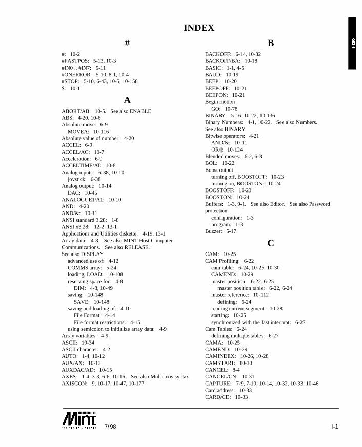
I-17/98
##: 10-2#FASTPOS: 5-13, 10-3#IN0 .. #IN7: 5-11#ONERROR: 5-10, 8-1, 10-4#STOP: 5-10, 6-43, 10-5, 10-158$: 10-1
AABORT/AB: 10-5. See also ENABLEABS: 4-20, 10-6Absolute move: 6-9
MOVEA: 10-116Absolute value of number: 4-20ACCEL: 6-9ACCEL/AC: 10-7Acceleration: 6-9ACCELTIME/AT: 10-8Analog inputs: 6-38, 10-10
joystick: 6-38Analog output: 10-14
DAC: 10-45ANALOGUE1/A1: 10-10AND: 4-20AND/&: 10-11ANSI standard 3.28: 1-8ANSI x3.28: 12-2, 13-1Applications and Utilities diskette: 4-19, 13-1Array data: 4-8. See also MINT Host ComputerCommunications. See also RELEASE. See also DISPLAY
advanced use of: 4-12COMMS array: 5-24loading, LOAD: 10-108reserving space for: 4-8
DIM: 4-8, 10-49saving: 10-148
SAVE: 10-148saving and loading of: 4-10
File Format: 4-14File format restrictions: 4-15
using semicolon to initialize array data: 4-9Array variables: 4-9ASCII: 10-34ASCII character: 4-2AUTO: 1-4, 10-12AUX/AX: 10-13AUXDAC/AD: 10-15AXES: 1-4, 3-3, 6-6, 10-16. See also Multi-axis syntaxAXISCON: 9, 10-17, 10-47, 10-177
BBACKOFF: 6-14, 10-82BACKOFF/BA: 10-18BASIC: 1-1, 4-5BAUD: 10-19BEEP: 10-20BEEPOFF: 10-21BEEPON: 10-21Begin motion
GO: 10-78BINARY: 5-16, 10-22, 10-136Binary Numbers: 4-1, 10-22. See also Numbers. See also BINARYBitwise operators: 4-21
AND/&: 10-11OR/|: 10-124
Blended moves: 6-2, 6-3BOL: 10-22Boost output
turning off, BOOSTOFF: 10-23turning on, BOOSTON: 10-24
BOOSTOFF: 10-23BOOSTON: 10-24Buffers: 1-3, 9-1. See also Editor. See also Passwordprotection
configuration: 1-3program: 1-3
Buzzer: 5-17
CCAM: 10-25CAM Profiling: 6-22
cam table: 6-24, 10-25, 10-30CAMEND: 10-29master position: 6-22, 6-25
master position table: 6-22, 6-24master reference: 10-112
defining: 6-24reading current segment: 10-28starting: 10-25synchronized with the fast interrupt: 6-27
Cam Tables: 6-24defining multiple tables: 6-27
CAMA: 10-25CAMEND: 10-29CAMINDEX: 10-26, 10-28CAMSTART: 10-30CANCEL: 8-4CANCEL/CN: 10-31CAPTURE: 7-9, 7-10, 10-14, 10-32, 10-33, 10-46Card address: 10-33CARD/CD: 10-33
INDEX
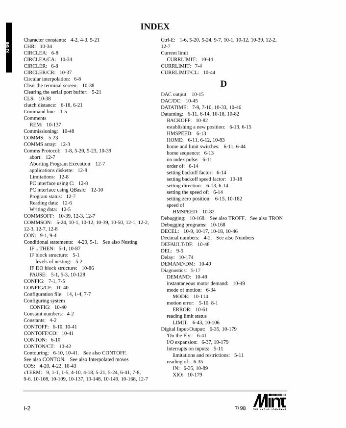
I-2 7/98
Character constants: 4-2, 4-3, 5-21CHR: 10-34CIRCLEA: 6-8CIRCLEA/CA: 10-34CIRCLER: 6-8CIRCLER/CR: 10-37Circular interpolation: 6-8Clear the terminal screen: 10-38Clearing the serial port buffer: 5-21CLS: 10-38clutch distance: 6-18, 6-21Command line: 1-5Comments
REM: 10-137Commissioning: 10-48COMMS: 5-23COMMS array: 12-3Comms Protocol: 1-8, 5-20, 5-23, 10-39
abort: 12-7Aborting Program Execution: 12-7applications diskette: 12-8Limitations: 12-8PC interface using C: 12-8PC interface using QBasic: 12-10Program status: 12-7Reading data: 12-6Writing data: 12-5
COMMSOFF: 10-39, 12-3, 12-7COMMSON: 5-24, 10-1, 10-12, 10-39, 10-50, 12-1, 12-2,12-3, 12-7, 12-8CON: 9-1, 9-4Conditional statements: 4-20, 5-1. See also Nesting
IF .. THEN: 5-1, 10-87IF block structure: 5-1
levels of nesting: 5-2IF DO block structure: 10-86PAUSE: 5-1, 5-3, 10-128
CONFIG: 7-1, 7-5CONFIG/CF: 10-40Configuration file: 14, 1-4, 7-7Configuring system
CONFIG: 10-40Constant numbers: 4-2Constants: 4-2CONTOFF: 6-10, 10-41CONTOFF/CO: 10-41CONTON: 6-10CONTON/CT: 10-42Contouring: 6-10, 10-41. See also CONTOFF.See also CONTON. See also Interpolated movesCOS: 4-20, 4-22, 10-43cTERM: 9, 1-1, 1-5, 4-10, 4-18, 5-21, 5-24, 6-41, 7-8,9-6, 10-108, 10-109, 10-137, 10-148, 10-149, 10-168, 12-7
Ctrl-E: 1-6, 5-20, 5-24, 9-7, 10-1, 10-12, 10-39, 12-2, 12-7Current limit
CURRLIMIT: 10-44CURRLIMIT: 7-4CURRLIMIT/CL: 10-44
DDAC output: 10-15DAC/DC: 10-45DATATIME: 7-9, 7-10, 10-33, 10-46Datuming: 6-11, 6-14, 10-18, 10-82
BACKOFF: 10-82establishing a new position: 6-13, 6-15HMSPEED: 6-13HOME: 6-11, 6-12, 10-83home and limit switches: 6-11, 6-44home sequence: 6-13on index pulse: 6-11order of: 6-14setting backoff factor: 6-14setting backoff speed factor: 10-18setting direction: 6-13, 6-14setting the speed of: 6-14setting zero position: 6-15, 10-182speed of
HMSPEED: 10-82Debugging: 10-168. See also TROFF. See also TRONDebugging programs: 10-168DECEL: 10-9, 10-17, 10-18, 10-46Decimal numbers: 4-2. See also NumbersDEFAULT/DF: 10-48DEL: 9-5Delay: 10-174DEMAND/DM: 10-49Diagnostics: 5-17
DEMAND: 10-49instantaneous motor demand: 10-49mode of motion: 6-34
MODE: 10-114motion error: 5-10, 8-1
ERROR: 10-61reading limit status
LIMIT: 6-43, 10-106Digital Input/Output: 6-35, 10-179
'On the Fly': 6-41I/O expansion: 6-37, 10-179Interrupts on inputs: 5-11
limitations and restrictions: 5-11reading of: 6-35
IN: 6-35, 10-89XIO: 10-179
INDEX
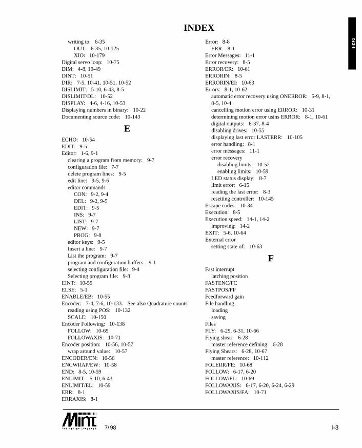
I-37/98
writing to: 6-35OUT: 6-35, 10-125XIO: 10-179
Digital servo loop: 10-75DIM: 4-8, 10-49DINT: 10-51DIR: 7-5, 10-41, 10-51, 10-52DISLIMIT: 5-10, 6-43, 8-5DISLIMIT/DL: 10-52DISPLAY: 4-6, 4-16, 10-53Displaying numbers in binary: 10-22Documenting source code: 10-143
EECHO: 10-54EDIT: 9-5Editor: 1-6, 9-1
clearing a program from memory: 9-7configuration file: 7-7delete program lines: 9-5edit line: 9-5, 9-6editor commands
CON: 9-2, 9-4DEL: 9-2, 9-5EDIT: 9-5INS: 9-7LIST: 9-7NEW: 9-7PROG: 9-8
editor keys: 9-5Insert a line: 9-7List the program: 9-7program and configuration buffers: 9-1selecting configuration file: 9-4Selecting program file: 9-8
EINT: 10-55ELSE: 5-1ENABLE/EB: 10-55Encoder: 7-4, 7-6, 10-133. See also Quadrature counts
reading using POS: 10-132SCALE: 10-150
Encoder Following: 10-138FOLLOW: 10-69FOLLOWAXIS: 10-71
Encoder position: 10-56, 10-57wrap around value: 10-57
ENCODER/EN: 10-56ENCWRAP/EW: 10-58END: 8-5, 10-59ENLIMIT: 5-10, 6-43ENLIMIT/EL: 10-59ERR: 8-1ERRAXIS: 8-1
Error: 8-8ERR: 8-1
Error Messages: 11-1Error recovery: 8-5ERROR/ER: 10-61ERRORIN: 8-5ERRORIN/EI: 10-63Errors: 8-1, 10-62
automatic error recovery using ONERROR: 5-9, 8-1,8-5, 10-4cancelling motion error using ERROR: 10-31determining motion error usins ERROR: 8-1, 10-61digital outputs: 6-37, 8-4disabling drives: 10-55displaying last error LASTERR: 10-105error handling: 8-1error messages: 11-1error recovery
disabling limits: 10-52enabling limits: 10-59
LED status display: 8-7limit error: 6-15reading the last error: 8-3resetting controller: 10-145
Escape codes: 10-34Execution: 8-5Execution speed: 14-1, 14-2
improving: 14-2EXIT: 5-6, 10-64External error
setting state of: 10-63
FFast interrupt
latching positionFASTENC/FCFASTPOS/FPFeedforward gainFile handling
loadingsaving
FilesFLY: 6-29, 6-31, 10-66Flying shear: 6-28
master reference defining: 6-28Flying Shears: 6-28, 10-67
master reference: 10-112FOLERR/FE: 10-68FOLLOW: 6-17, 6-20FOLLOW/FL: 10-69FOLLOWAXIS: 6-17, 6-20, 6-24, 6-29FOLLOWAXIS/FA: 10-71
INDEX
I-4 7/98
Following error: 7-6. See also Maximum following errormaximum following error
MFOLERR: 10-113reading following error
FOLERR: 10-68FOR .. NEXT: 5-4, 10-72
levels of nesting: 5-4Formatted input: 10-96Formatted output: 5-15, 5-16, 10-107, 10-135FREE: 9-6Free memory: 9-1, 9-6FREQ/FQ: 10-73Frequency output FREQ: 10-73
GGAIN: 7-3GAIN/GN: 10-74Gearbox. See Software gearboxesGEARD: 6-20GEARD/GD: 10-75GEARN: 6-20GEARN/GR: 10-76GO: 3-1, 6-9, 10-78GOSUB: 5-8, 10-79GOTO: 10-81
HHalt program execution: 10-128HMSPEED: 6-13, 10-18HMSPEED/HS: 10-82HOME: 6-11Home and limit switches: 6-11HOME/HM: 10-83Homing: 6-12, 10-83Host computer communications: 13-1
IIDLE: 3-4, 6-42, 10-128IDLE/ID: 10-85IF .. DO: 5-1, 10-86IF .. THEN: 5-1, 10-87IMASK/IM: 10-88Improving Execution Speed: 14-2IN: 6-35, 10-89. See InterruptsIN0/I0 .. IN7/I7: 10-90INCA: 6-4INCA/IA: 10-91INCR: 6-4INCR/IR: 10-93Infeed: 6-17, 10-122, 10-138, 10-175. See also Pulsefollowing
OFFSET: 10-122WRAP: 10-176
INKEY: 5-20INKEY/IK: 10-94INPUT: 5-14, 5-16, 5-20, 10-95Input and Output: 5-14. See also Digital input/outputInputs: 6-41. See also Digital input/outputINS: 9-7INT: 4-20, 10-96Integer value
INT: 10-96Integral gain: 7-2
KINT: 7-2, 10-101Integration range: 7-4
KINTRANGE: 7-4Interpolated motion: 6-5Interpolated Moves: 6-4, 6-5. See also Positional control
absolute circular interpolationCIRCLEA: 10-35
absolute linear interpolationVECTORA: 10-169
circular Interpolation: 6-8CIRCLE: 6-8
contouring: 6-8linear interpolation: 6-6relative circular interpolation
CIRCLER: 10-37relative linear interpolation
VECTORR: 10-170Interrupts: 5-11, 10-3
disabling: 10-51enabling: 10-55fast interrupt: 10-66limitations and restrictions: 5-11pending interrupts: 10-97setting a mask: 10-88
Inverter Control: 7-5, 10-51controlling direction: 7-5
IPEND/IP: 10-97
JJOG: 6-2JOG/JG: 10-98Joystick: 6-38
example program: 4-13
KKeyboard: 5-14
waiting for key press: 5-3Keypad
tactile feedback: 10-21Keypad and display: 5-14, 5-17, 10-100
buzzer: 5-17defining keys: 10-100disabling using TERM: 10-160
INDEX
I-57/98
locating the cursor: 10-109writing to using LINE: 10-107
KEYS: 10-100KINT: 7-3KINT/KI: 10-101KINTRANGE: 7-4, 10-102KINTRANGE/KR: 10-102KVEL: 7-3KVEL/KV: 10-103KVELFF: 7-3KVELFF/KF: 10-104
LLabels: 10-2
GOTO: 10-81LASTERR: 8-3, 10-105LCD display: 5-17, 10-107LED: 8-7LED status display: 8-7, 10-105
LED keyword: 8-7LED/LD: 10-105LIMIT: 6-43Limit switches. See also Error recovery
disablingDISLIMIT: 5-10, 6-43, 10-52
enabling: 10-55ENABLE: 10-55ENLIMIT: 5-10, 6-43
LIMIT: 6-43, 10-106LIMIT/LM: 10-106
LINE: 5-16, 10-107, 10-136Line editor: 9-1Linear Interpolation: 6-6LIST: 9-7LOAD: 4-17, 10-108Loading programs and data: 10-108LOCATE: 10-109Logical operators: 10-11. See also Operators
AND/&: 10-11NOT/!: 10-120OR/|: 10-124
LOOP .. ENDL: 5-6, 10-110Loops: 5-4. See also Nesting
Nesting. See also continuous loops: 5-6EXIT: 10-64FOR .. NEXT: 5-4, 10-72LOOP .. ENDL: 5-6, 10-110REPEAT .. UNTIL: 5-5, 10-144terminating from: 5-7, 10-64WHILE .. ENDW: 5-5, 10-175
LOOPTIME/LT: 10-111
MMASTERINC: 6-18, 6-19, 6-20, 10-26, 10-112MASTERINC/MI: 10-112Mathematical operators: 4-20Maximum following error: 7-6. See also MFOLERR
MFOLERR: 10-113Memory: 9-1
determining free memory: 9-6out of memory: 11-2
Memory Expansion: 9-2, 10-121MFOLERR: 7-6, 10-113MFOLERR/MF: 10-113Micro stepper
configuring forCONFIG: 10-40
MINTexecution speed: 14-1
MINT Editor: 9-1MINT Host Computer Communications: 12-1. See also COMMSON. See also Comms protocolMINT Host Computer Protected Protocol: 5-23MINT Versions: 1-7MINT/3.28: 1-8, 13-1
applications diskette: 13-1buffered moves: 13-8commands: 13-7GO command: 13-8reading data: 13-6status request: 10-182writing data: 13-6
MOD: 4-20MODE: 6-34, 8-8MODE/MD: 10-114Modular arithmetic: 4-20Motion: 10-85
checking for idle: 10-85GO: 10-78IDLE: 10-85MODE: 6-34, 10-115
Motion commands: 3-1Motion error: 8-5Motion Variables: 3-1, 4-6
range checking: 3-1Motor demand
DEMAND: 10-49Motor type: 10-40
CONFIG: 10-40Move Buffer: 6-9Move pending: 6-10, 6-41MOVEA/MA: 10-116MOVECAM: 8-8, 10-27, 10-79, 10-112, 10-115, 10-150,10-158
INDEX
I-6 7/98
MOVER/MR: 10-118Multi-Axis Syntax: 3-2
AXES: 10-16default using AXES: 3-2reading more than 1 axis: 3-4referencing axes: 3-2using: 3-2using, to skip axes: 3-2
Multi-drop RS485: 1-1, 1-7, 10-1, 13-1card address: 10-33
Multi-drop systems: 1-8
NNesting: 5-7NEW: 9-7NOT: 4-20NOT/!: 10-120Numbers: 4-1. See also Operators
binary numbers: 4-1, 4-21character constants: 4-2, 5-21constant numbers: 4-2scaled integers: 4-1
OOFFLINE: 4-10, 4-11, 4-15, 9-2, 10-50, 10-121OFFSET: 6-17, 6-18, 6-19OFFSET/OF: 10-122ONERROR: 5-10, 8-5Operators
absolute valueABS: 4-20, 10-6
bitwise operatorsAND/&: 10-11AND/&, OR/|: 4-20OR/|: 10-124
Integer valueINT: 4-20, 10-96
logical operators: 10-11AND/&: 10-11AND/&, OR/, NOT/!: 4-21NOT/!: 10-120
mathematical operators– + / *: 4-20
performing logical operations: 4-21priority: 4-20relational operators: 4-21
< > = <= >= <>: 4-21Option card
reading address spacePEEK: 10-129
writing to address spacePOKE: 10-131
OR: 4-20OR/|: 10-124Out of memory: 11-2OUT/OT: 10-125OUT0/O0 .. OUT7/O7: 10-127Output Errors On SmartMove
Over current: 8-8Over temperature: 8-8Short circuit: 8-8
Outputs: 6-41, 10-125. See also Digital input/output
PPassword Protection: 9-4, 10-137PAUSE: 5-3, 10-128PEEK/PK: 10-129POFF: 10-131POKE: 10-131PON: 10-132POS: 6-13, 10-182POS/PS: 10-132Position
latching using fast interrupt: 10-66reading
POS: 10-132reading using ENCODER: 10-56writing
POS: 10-133Positional control: 6-3
absolute positional control: 6-3, 10-116correctly for slip: 10-93incremental positional control: 6-4, 10-118interpolated moves: 6-5relative positional control: 10-118velocity profile: 6-9
ACCEL: 6-9RAMP: 6-9, 10-140SPEED: 6-9
Positional error: 7-6Positional moves. See Positional control
defining new end position: 6-4, 10-91, 10-93interpolated moves: 10-35, 10-169, 10-170
Positional Resolution: 7-6quadrature counts: 7-6SCALE: 7-6, 10-150
Positioning the cursor: 10-109LOCATE: 10-109
Power to motors: 10-151Pre-defined constant keywords: 4-3PRESCALE: 10-134PRINT: 5-15PRINT/?: 10-135Process MINT: 1-7PROG: 9-8
INDEX
I-77/98
Program buffers: 1-3Program execution
AUTO: 10-12debugging: 10-168delaying: 10-174RUN: 8-5, 10-147terminating from program
END: 10-59terminating using keyboard: 10-12
Program Structure: 2-1Proportional gain: 7-3
GAIN: 7-3, 10-74PROTECT: 9-4, 10-137Protected protocol: 12-1. See also Comms protocol.See also COMMSON
COMMSON: 10-39PULSE: 6-15Pulse Following: 6-15, 10-122. See also Infeed. See also FOLLOW
PULSE: 6-15, 10-138PULSEVEL: 10-139reading follower input: 10-163stepper controller: 6-15TIMER: 10-163velocity of pulse train: 10-140WRAP: 10-176
PULSE/PU: 10-138PULSEVEL/PV: 10-139
QQuadrature counts: 7-6. See also SCALE
RRAMP: 6-9RAMP/RP: 10-140Reading serial buffer: 10-94READKEY: 5-17READKEY/RK: 10-141Relational operators: 4-20Relative move
MOVER: 10-118RELEASE: 4-6, 4-17, 10-143REM: 10-143REPEAT .. UNTIL: 10-144
levels of nesting: 5-5RESET: 6-43, 8-5RESET/RE: 10-145Resetting the system: 10-48RETURN: 5-8, 8-5, 10-147RS232/485: 5-14RS485: 1-1, 5-14, 12-1, 13-1RUN: 8-5, 10-147
SS ramps: 6-9
RAMP: 6-9SAVE: 4-17, 10-148Saving programs and data: 10-148SCALE: 7-6SCALE/SF: 10-150Scaling
example of: 7-6Separating multiple statement: 10-2Serial buffer
reading: 10-94Serial port: 10-19
disabling using TERM: 10-160setting Baud rate: 10-19
Serial port buffer: 5-20clearing: 5-5
Servo Loop: 7-2, 10-111tuning: 10-14
Servo loop gains: 7-2, 7-4, 7-7current limit
CURRLIMIT: 10-44integral range
KINT: 10-101integration range: 10-102
KINTRANGE: 10-102proportional gain
GAIN: 10-74setting up: 7-4velocity feedback gain
KVEL: 10-103velocity feedforward gain
KVELFF: 10-104Servo loop time
defining: 10-111Servo motors
configuring forCONFIG: 10-40
Servo power: 10-151power off
SERVOFF: 10-153power on
SERVON: 10-154power to current position
SERVOC: 10-151SERVOC/SC: 10-151SERVOFF/SO: 10-152SERVON/SV: 10-154Setting sysstem parameters: 7-7Setting up servo loop gains: 7-4SIN: 4-20, 4-22, 10-155SmartMove: 9, 4-10, 10-178
INDEX
I-8 7/98
Software Gearbox: 6-17, 6-19, 6-20, 6-21, 10-77CAM profiling. See clutch distance: 6-18, 6-21
SPEED: 6-9. See also VelocitySpeed Control: 6-2
JOG: 6-2, 10-98SPEED/SP: 10-155Status Display: 8-7, 10-105Stepper control
BEEPOFF: 10-21BEEPON: 10-21frequency output: 10-73
Stepper controller: 6-15Stepper motors: 10-40
configuring for: 10-40CONFIG: 10-40
STOP: 3-1, 6-16STOP Input: 6-42, 10-158
reading input: 10-159reading value of: 6-42STOP subroutine: 10-5STOPSW: 10-159
Stop motioncontrolled stop
STOP: 10-157crash stop
ABORT: 10-5STOP subroutine: 5-10, 10-5STOP/ST: 10-157STOPMODE: 10-158STOPSW: 6-43STOPSW/SS: 10-159Subroutine label: 10-2Subroutines: 5-8
calling: 5-8, 10-80defining: 5-8GOSUB: 5-8, 10-79interrupt routines: 5-11labels: 5-8, 10-2maximum number of in a program: 5-9RETURN: 5-8, 10-147
System commissioning: 10-13System Software Configuration: 7-1
TTAN: 4-20, 4-22, 10-160TERM/TM: 10-160Terminal Input/Output: 5-14
associated keywordsBEEP: 10-20BEEPOFF: 10-21BEEPON: 10-21
BINARY: 10-22BOL (Beginning of line): 10-22CHR: 10-34CLS: 10-38INKEY: 10-94INPUT: 5-16, 10-95LINE: 10-107LOCATE: 10-109POFF: 10-131PON: 10-132PRINT: 5-15, 10-135TERM: 10-160
character constants: 5-21clearing the serial port buffer: 5-21controlling use of: 10-160formatted input: 5-16formatted output: 5-16keypad and display: 5-17positioning the cursor: 10-22, 10-109reading the serial port buffer: 5-21serial port buffer: 5-20write to a line: 5-15
Terminate motion. See also Ctrl-Econtrolled stop
STOP: 10-157crash stop
ABORT: 10-6Terminate program execution: 1-4, 1-6Terminating loops: 5-7Terminating program execution: 1-6. See also Ctrl-E
END: 8-5Three channel encoder interface board: 10-177TIME/TE: 10-162TIMER: 6-16, 10-163Timer input: 10-163TIMER/TI: 10-163Timing program execution: 10-162Torque Control: 6-1
terminating: 6-1Torque: 6-1, 10-164
TORQUE/TQ: 10-164Trapezoidal profile: 6-9TRIGGER: 6-33, 10-165, 10-166, 10-167Triggered Moves: 6-33Trigonometric Functions: 4-22
COS: 10-43SIN: 10-155TAN: 10-160
TROFF: 10-167TRON: 10-168Tuning servo loop: 10-14
INDEX
I-97/98
UUni-directional control. See also Inverter controlUser timer: 10-162User units
setting: 10-150User variables: 4-5
VVariable software gearbox: 6-22. See also Cam profilingVariables: 4-5. See also Numbers. See also Motionvariables
array dataDIM: 10-49reserving space for: 10-49
associated keywordsDISPLAY: 4-6RELEASE: 4-6
clearing variables from memory: 4-6, 10-143clearing variables from memory during runtime: 4-6declaring user variables: 4-5displaying defined variables: 4-5, 10-53motion variables: 4-21
Motion variables. See non-volatile: 4-6
VECTORA: 6-6VECTORA/VA: 10-169VECTORR: 6-6VECTORR/VR: 10-170VEL/VL: 10-172Velocity. See also SPEED
reading using VEL: 10-172Velocity control: 10-98Velocity feedback gain: 7-2
KVEL: 7-2, 10-103Velocity feedforward: 7-2Velocity feedforward gain
KVELFF: 7-3Velocity Profile: 6-9. See also S ramps acceleration
ACCEL: 10-7ACCELTIME: 10-8RAMP: 10-140
VER: 10-173Version of MINT: 10-173Versions: 1-7VPU: 10-156
WWAIT/WT: 10-174WHILE .. ENDW: 5-5, 10-175WRAP: 6-16, 10-139WRAP/WR: 10-176
XXENCODER: 10-18, 10-72, 10-134, 10-177, 10-178XIO: 10-179XIO/XI: 10-179XIO0..7: 10-179XOUT/XO: 10-181
ZZERO: 6-15Zero position. See also DatumingZERO/ZR: 10-182ZZ: 10-183
INDEX

I-10 7/98
INDEX

© Baldor Electric CompanyMN1260
Printed in USA7/98 Custom 15,000
Worldwide OfficesUSA
Baldor Electric Company • P. O. Box 2400 • Fort Smith, AR 72902-2400 USATel: 1 501 646-4711• Fax: 1 501 648-5792 • E-mail: [email protected]
United KingdomBaldor Optimised Control • 178-180 Hotwell Road • Bristol BS8 4RP, UK
Tel: 44 (0)117 915 3200 • Fax: 44 (0)117 915 3201 • Web site: www.baldor.co.uk
EuropeBaldor ASR AG • Tel: 41 (0)52 647 4700 • Fax: 41 (0)52 659 2394
Baldor ASR GmbH • Tel: 49 (0)89 90508-0 • Fax: 49 (0)89 90508-491
AustraliaAustralian Baldor PTY., LTD. • Tel: 61 2 9674 5455 • Fax: 61 2 9674 2495
Singapore (F.E.)Baldor Electric PTE.LTD. • Tel: 65 744 2572 • Fax: 65 747 1708
www.baldor.com