Embed Size (px)
Citation preview
Minority Leaders SensorsProgram Review
Presented byDimitris C. Lagoudas
Gary D. Seidel
Micromechanics Modeling of the Electrical Conductivity of Carbon Nanotube-Epoxy
Nanocomposites
25 – 28 February 2008

2
Project Outline
• Project Members• Problem Statement • Approach• Accomplishments/Successes • Status Summary
3
Project Members
• AF POC: Dr. Ajit Roy• Project Lead: Dr. Dimitris C. Lagoudas• Research Collaborators:
– Dr. Gary D. Seidel (Postdoc)
• Students:– Kelli Boehringer (Undergraduate)
4
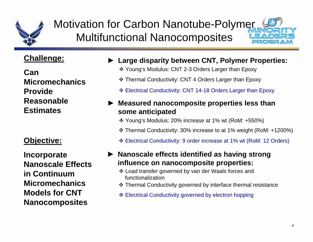
� Electrical Conductivity governed by electron hopping
� Electrical Conductivity: 9 order increase at 1% wt (RoM: 12 Orders)
Motivation for Carbon Nanotube-Polymer Multifunctional Nanocomposites
► Large disparity between CNT, Polymer Properties:
► Measured nanocomposite properties less than some anticipated
� Young’s Modulus: CNT 2-3 Orders Larger than Epoxy
� Electrical Conductivity: CNT 14-18 Orders Larger than Epoxy
� Thermal Conductivity: CNT 4 Orders Larger than Epoxy
� Young’s Modulus: 20% increase at 1% wt (RoM: +550%)
� Thermal Conductivity: 30% increase to at 1% weight (RoM: +1200%)
► Nanoscale effects identified as having strong influence on nanocomposite properties:� Load transfer governed by van der Waals forces and
functionalization� Thermal Conductivity governed by interface thermal resistance
Objective:
Incorporate Nanoscale Effects in Continuum Micromechanics Models for CNT Nanocomposites
Challenge:
Can Micromechanics Provide Reasonable Estimates
5
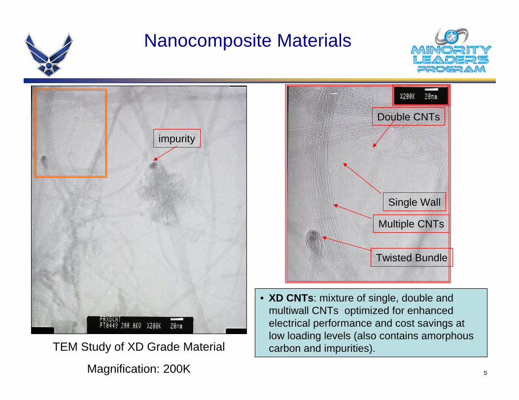
Nanocomposite Materials
impurity
Magnification: 200K
TEM Study of XD Grade Material
Single Wall
Double CNTs
Multiple CNTs
Twisted Bundle
• XD CNTs: mixture of single, double and multiwall CNTs optimized for enhanced electrical performance and cost savings at low loading levels (also contains amorphous carbon and impurities).
6
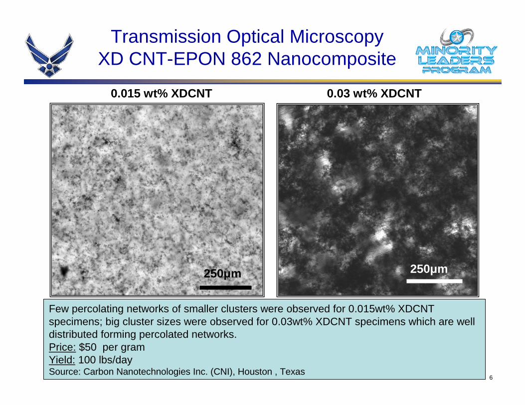
Transmission Optical MicroscopyXD CNT-EPON 862 Nanocomposite
0.015 wt% XDCNT
Few percolating networks of smaller clusters were observed for 0.015wt% XDCNT specimens; big cluster sizes were observed for 0.03wt% XDCNT specimens which are well distributed forming percolated networks.Price: $50 per gramYield: 100 lbs/day Source: Carbon Nanotechnologies Inc. (CNI), Houston , Texas
250µm
0.03 wt% XDCNT
250µm
7
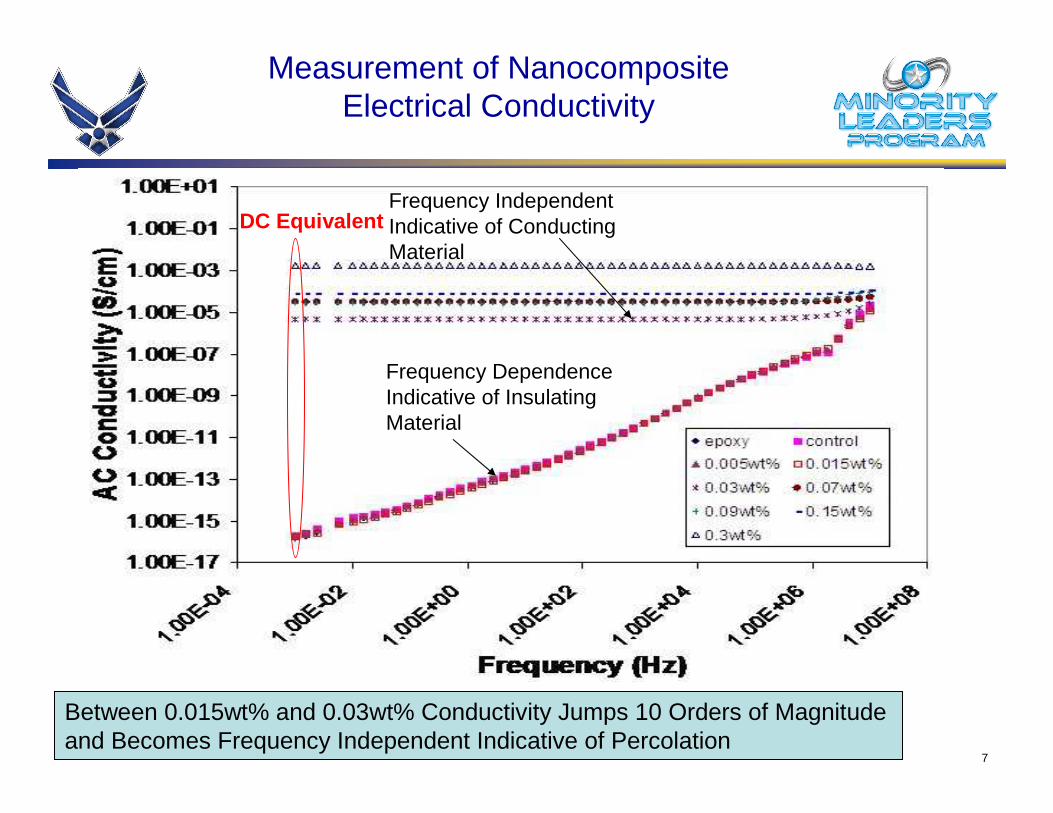
Between 0.015wt% and 0.03wt% Conductivity Jumps 10 Orders of Magnitude and Becomes Frequency Independent Indicative of Percolation
Frequency Dependence Indicative of Insulating Material
Frequency Independent Indicative of Conducting Material
Measurement of Nanocomposite Electrical Conductivity
DC Equivalent
8
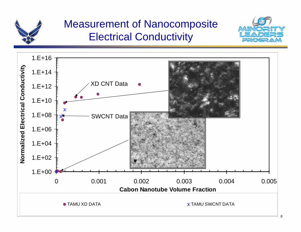
Measurement of Nanocomposite Electrical Conductivity
1.E+00
1.E+02
1.E+04
1.E+06
1.E+08
1.E+10
1.E+12
1.E+14
1.E+16
0 0.001 0.002 0.003 0.004 0.005Cabon Nanotube Volume Fraction
Nor
mal
ized
Ele
ctric
al C
ondu
ctiv
ity
TAMU XD DATA TAMU SWCNT DATA
SWCNT Data
XD CNT Data

9
Approach
� Generate micromechanics model for predicting the effective electrical conductivity of XD CNT nanocomposites
� Study the effects of metallic vs. non-metallic CNT fraction
� Study the effects of clustering of nanotube bundles
� Study the non-continuum effects of electron hopping

10
� Dispersion difficulties lead to clustering of carbon nanotubes
� How to draw needed input from molecular dynamics simulations or nanoscale measurements
Nanocomposite Modeling Challenges
• Specimens Provided by Dr. E. Barrera, Rice UniversityTEM Imaging by Piyush Thakre, Texas A&M University
► Features which may have strong influence on model predictions:
� Interphase regions due to functionalization
� Orientation Effects due to Difficulty in alignment of carbon nanotubes
� Curvature/twisting effects of carbon nanotubes
� Nanoscale Load transfer
� Accounting for non-continuum effects
250 nm
100 nm100 nm
100 nm
20 nm
Objective:
Incorporate Nanoscale Effects in Continuum Micromechanics Models for CNT Nanocomposites

11
Micromechanics Model for Nanocomposite Electrical Conductivity
1y
3y2y
Macroscale Boundary Value Problem
1x
3x2x
ˆi i i iJ n J n=
ˆφ φ=
Effective CNT + Interphase
2y% 3y%1y%
Microscale RVE
Nanoscale RVE (Composite Cylinder Assemblage)
Interphase
2y% 3y%
1y%
CNT
Effective Nanocomposite
Governing Differential Equations: Electrical ConductivityConservation of Charge Electric Field Electric Flux Constitutive Relation
0∇ ⋅ =J φ= −∇E eff=J σ E
12
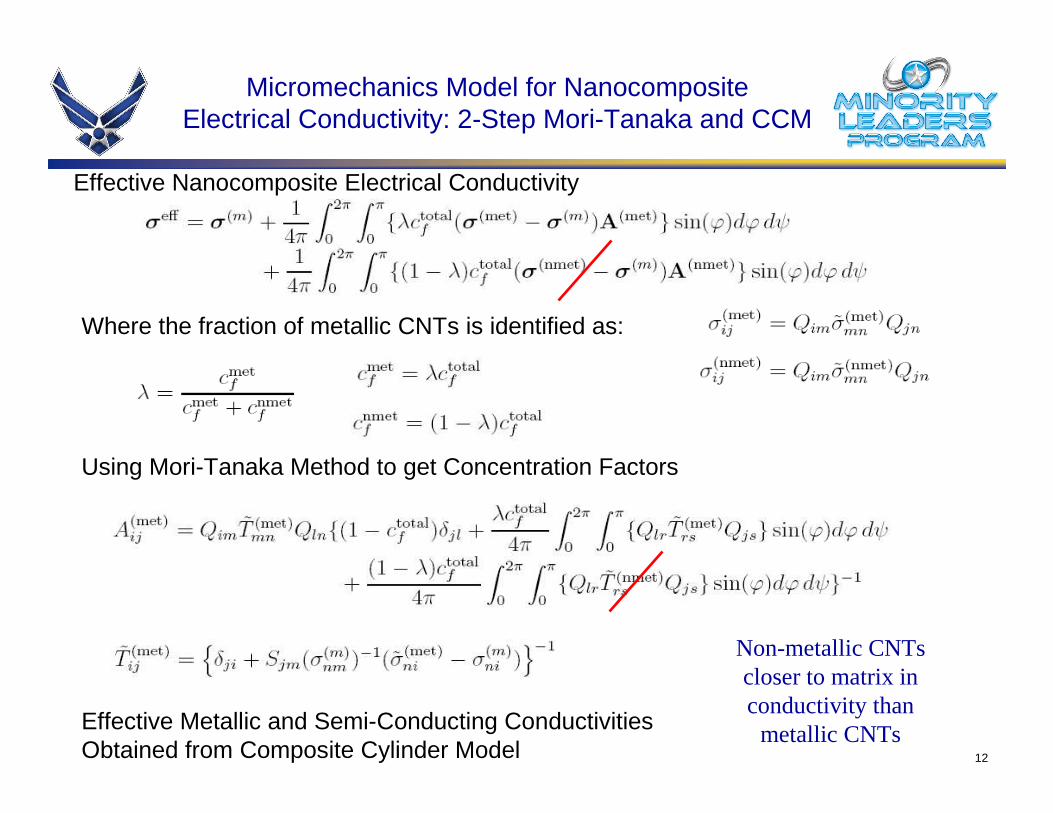
Micromechanics Model for Nanocomposite Electrical Conductivity: 2-Step Mori-Tanaka and CCM
Effective Nanocomposite Electrical Conductivity
Where the fraction of metallic CNTs is identified as:
Using Mori-Tanaka Method to get Concentration Factors
Effective Metallic and Semi-Conducting Conductivities Obtained from Composite Cylinder Model
Non-metallic CNTscloser to matrix in conductivity than metallic CNTs

13
Electron Hop Layer
Matrix Material
2x 3x
1x
Model Parameters
CNT
Use micromechanics model to investigate both electron hopping and formation of conductive paths in a parametric study for XD CNT Nanocomposites
� Electron Hopping Parameters: range and frequency (thickness & conductivity)
� Metallic vs Non-Metallic CNT Fraction
� Distribution of CNTs: conductive path formation (effective aspect ratio)
� Fraction of SWCNT vs MWCNT in XD
� Geometry of CNTs: radius, length, number of walls
� Parameters or Interest:
Btwn Matrix and CNTBtwn Matrix and CNTHopping Conductivity
5nm – 30nm5nm – 30nmHopping Range
100 to Infinite500 to InfiniteAspect Ratio
1/3 to 11/3 to 1Metallic Fraction (λ)
MWCNTSWCNTVariable
� Estimated Ranges for Parameters or Interest:

14
1.E+00
1.E+02
1.E+04
1.E+06
1.E+08
1.E+10
1.E+12
1.E+14
1.E+16
0 0.001 0.002 0.003 0.004 0.005Cabon Nanotube Volume Fraction
Nor
mal
ized
Ele
ctric
al C
ondu
ctiv
ity
TAMU XD DATA TAMU SWCNT DATA
MWCNT AR = 100 Micromechanics Model SWCNT AR = 500 Micromechanics Model
MWCNT 100x AR Micromechanics Model SWCNT 100x AR Micromechanics Model
SWCNT Data
SWCNT Model
λ = 1/3
totalfc
XD CNT Data
MWCNT Model
SWCNT Model 100x AR
MWCNT Model 100x AR
1.E+00
1.E+02
1.E+04
1.E+06
1.E+08
1.E+10
1.E+12
1.E+14
1.E+16
0 0.001 0.002 0.003 0.004 0.005Cabon Nanotube Volume Fraction
Nor
mal
ized
Ele
ctric
al C
ondu
ctiv
ity
TAMU XD DATA TAMU SWCNT DATA
MWCNT AR = 100 Micromechanics Model SWCNT AR = 500 Micromechanics Model
SWCNT Data
SWCNT Model
λ = 1/3
totalfc
XD CNT Data
MWCNT Model
Effects of Aspect Ratio on Nanocomposite Conductivity
1.E+00
1.E+02
1.E+04
1.E+06
1.E+08
1.E+10
1.E+12
1.E+14
1.E+16
0 0.001 0.002 0.003 0.004 0.005Cabon Nanotube Volume Fraction
Nor
mal
ized
Ele
ctric
al C
ondu
ctiv
ity
TAMU XD DATA TAMU SWCNT DATAMWCNT AR = 100 Micromechanics Model SWCNT AR = 500 Micromechanics ModelMWCNT 100x AR Micromechanics Model SWCNT 100x AR Micromechanics ModelMWCNT Infinite AR Micromechanics Model SWCNT Infinite AR Micromechanics Model
SWCNT Data
SWCNT Model
λ = 1/3
totalfc
XD CNT Data
MWCNT Model
SWCNT Model 100x AR
MWCNT Model 100x AR
SWCNT Model Infinite AR
MWCNT Model Infinite AR

15
Effects of Electron Hopping on Nanocomposite Conductivity
1.E+00
1.E+02
1.E+04
1.E+06
1.E+08
1.E+10
1.E+12
1.E+14
1.E+16
0 0.001 0.002 0.003 0.004 0.005Cabon Nanotube Volume Fraction
Nor
mal
ized
Ele
ctric
al C
ondu
ctiv
ity
TAMU XD DATA TAMU SWCNT DATA
SWCNT AR = 5000 Micromechanics Model SWCNT Infinite AR Micromechanics Model
SWCNT Model w/ 30nm Hop Cond 1e10xMatrix SWCNT Model w/ 131nm Hop Cond 1e10xMatrix
SWCNT Data
XD CNT Data
Electron HoppingRange: 30nmConductivity: 1E10 x Matrix(percolation at 0.011)
Electron HoppingRange: 130nmConductivity: 1E10 x Matrix
SWCNT Model Infinite AR
SWCNT Model
λ = 1/3

16
1.E+00
1.E+02
1.E+04
1.E+06
1.E+08
1.E+10
1.E+12
1.E+14
1.E+16
0 0.001 0.002 0.003 0.004 0.005Cabon Nanotube Volume Fraction
Nor
mal
ized
Ele
ctric
al C
ondu
ctiv
ity
TAMU XD DATA TAMU SWCNT DATA
SWCNT AR = 5000 Micromechanics Model SWCNT Infinite AR Micromechanics Model
SWCNT All Metallic
SWCNT Data
XD CNT Data
SWCNT Model Infinite AR
SWCNT Model 1/3 Metallic
SWCNT Model All Metallic
1.E+00
1.E+02
1.E+04
1.E+06
1.E+08
1.E+10
1.E+12
1.E+14
1.E+16
0 0.001 0.002 0.003 0.004 0.005Cabon Nanotube Volume Fraction
Nor
mal
ized
Ele
ctric
al C
ondu
ctiv
ity
TAMU XD DATA TAMU SWCNT DATA
SWCNT AR = 5000 Micromechanics Model SWCNT Infinite AR Micromechanics Model
SWCNT Model w/ 30nm Hop Cond 1e10xMatrix SWCNT Model w/ 131nm Hop Cond 1e10xMatrix
SWCNT Data
XD CNT Data
Electron HoppingRange: 30nm, 1/3 Metallic
Electron HoppingRange: 130nm,1/3 Metallic
SWCNT Model Infinite AR
SWCNT Model 1/3 Metallic1.E+00
1.E+02
1.E+04
1.E+06
1.E+08
1.E+10
1.E+12
1.E+14
1.E+16
0 0.001 0.002 0.003 0.004 0.005Cabon Nanotube Volume Fraction
Nor
mal
ized
Ele
ctric
al C
ondu
ctiv
ity
TAMU XD DATA TAMU SWCNT DATASWCNT AR = 5000 Micromechanics Model SWCNT Infinite AR Micromechanics ModelSWCNT Model w/ 30nm Hop Cond 1e10xMatrix SWCNT Model w/ 131nm Hop Cond 1e10xMatrixSWCNT Model w/ 30nm Hop Cond 1e10xMatrix AM
SWCNT Data
XD CNT Data
Electron HoppingRange: 30nm, 1/3 Metallic
Electron HoppingRange: 130nm,1/3 Metallic
SWCNT Model Infinite AR
SWCNT Model 1/3 Metallic
Electron HoppingRange: 30nm, All Metallic
1.E+00
1.E+02
1.E+04
1.E+06
1.E+08
1.E+10
1.E+12
1.E+14
1.E+16
0 0.001 0.002 0.003 0.004 0.005Cabon Nanotube Volume Fraction
Nor
mal
ized
Ele
ctric
al C
ondu
ctiv
ity
TAMU XD DATA TAMU SWCNT DATASWCNT AR = 5000 Micromechanics Model SWCNT Infinite AR Micromechanics ModelSWCNT Model w/ 30nm Hop Cond 1e10xMatrix SWCNT Model w/ 131nm Hop Cond 1e10xMatrixSWCNT Model w/ 30nm Hop Cond 1e10xMatrix AM SWCNT Model w/ 131nm Hop Cond 1e10xMatrix AM
SWCNT Data
XD CNT Data
Electron HoppingRange: 30nm, 1/3 Metallic
Electron HoppingRange: 130nm,1/3 Metallic
SWCNT Model Infinite AR
SWCNT Model 1/3 Metallic
Electron HoppingRange: 130nm, All Metallic
Electron HoppingRange: 30nm, All Metallic
Effects of Metallic Fraction on Nanocomposite Conductivity

17
Conclusions and Future Work
� Conclusions• Nanocomposite effective electrical conductivity is sensitive to changes in
aspect ratio (clustering).
� Future Work• Parametric study on SWCNT vs MWCNT fraction
• Computational micromechanics clustering model• Computational micromechanics model for combined effects clustering and
electron hopping.
• Electron hopping can result in a significant low volume fraction percolation event for SWCNTs if the hopping range is on order of 130nm.
• Increases in metallic fraction of CNTs can further decrease low volume fraction percolation limit associated with electron hopping.
Initial indication is that XDCNT-epoxy nanocomposites are good for electrostatic discharge applications, but several model parameters need to explicitly identified to improve model predictions.

18
Acknowledgements:• The research acknowledges the support of U.S. Air Force AFRL Contract No. FA8650-
05-D-1912, Minority Leaders Program• Dr. Zoubeida Ounaies and Mr. Sumanth Banda at TAMU Electroactive Materials Lab• Dr. Yordanos Bistrat• Mr. Piyush Thakre for assistance with TEM imaging
Gary Don SeidelPostdoc
Texas A&M [email protected]
Dr. Dimitris LagoudasJohn and Bea Slattery Chair in Aerospace Engineering
Texas A&M [email protected]
Kelli BoehringerUndergraduate
Texas A&M [email protected]

19
Status Summary
• Summary Gantt Chart would be most helpful.• Show a Gantt Chart or timeline for the overall proj ect by quarters• Show a Gantt Chart or timeline for each step of the project• Indicate major and minor milestones for the current contract period
and projected key event beyond the contract period (include current period and future milestones on Gantt Chart or Time line)
Project Schedule
Project Oct
-06
Nov
-06
Dec
-06
Jan-
07
Feb
-07
Mar
-07
Apr
-07
May
-07
Jun-
07
Jul-0
7
Aug
-07
Sep
-07
2.1.x.x RF Sensors Research
2.1.x.x a Title of 2.1.x.x a
2.1.x.x b Title of 2.1.x.x b
2.1.x.x c Title of 2.1.x.x c
Q1 Q2 Q3 Q4
Today
I don’t have this information