Embed Size (px)
Citation preview
1
CHAPTER 1
INTRODUCTION
1.1 INTRODUCTION TO ROBOTICS
Robotics is the branch of mechanical engineering, electrical engineering and
computer science that deals with the design, construction, operation, and application
of robots, as well as computer systems for their control, sensory feedback, and
information processing.
These technologies deal with automated machines that can take the place of
humans in dangerous environments or manufacturing processes, or resemble humans in
appearance, behavior, and/or cognition. Many of today's robots are inspired by nature
contributing to the field of bio-inspired robotics.
The concept of creating machines that can operate autonomously dates back
to classical times, but research into the functionality and potential uses of robots did not
grow substantially until the 20th century. Throughout history, robotics has been often
seen to mimic human behavior, and often manage tasks in a similar fashion. Today,
robotics is a rapidly growing field, as technological advances continue research, design,
and building new robots serve various practical purposes, whether domestically,
commercially, or militarily. Many robots do jobs that are hazardous to people such as
defusing bombs, mines and exploring shipwrecks.
1.2 ETYMOLOGY OF ROBOT
The word robotics was derived from the word robot, which was introduced to the
public by Czech writer Karel Čapek in his play R.U.R. (Rossum's Universal Robots),
which was published in 1920. The word robot comes from the Slavic word robota, which
means labour.
According to the Oxford English Dictionary, the word robotics was first used in
print by Isaac Asimov, in his science fiction short story "Liar", published in May 1941 in
Astounding Science Fiction. Asimov was unaware that he was coining the term; since the
science and technology of electrical devices is electronics, he assumed robotics already
referred to the science and technology of robots.
2
1.3 AIM OF THE PROJECT
This project is basic stage of any automatic robot. The project uses micro-
controller AT89S52 as the controlling element.
This ROBOT has sufficient intelligence to cover the maximum area of provided
space. It uses IR (Infra-Red) sensors and two IR transmitting circuitry, which are used to
sense the obstacles coming in between the path of ROBOT. It will move in a particular
direction and avoid the obstacle which is coming in its path. When the obstacle comes in
path of robot IR beam is reflected from the obstacle then sensor gives zero voltage to µc.
This zero voltage is detected then µc decides to avoid the obstacle by taking left, right or
back turn. If the sensor gives +5v to µc that means there is no obstacle present in it path
so it goes straight until any obstacle is detected.
The IR transmitter circuits are fitted on front side of robot. The IR sensor is
placed near to transmitters‟ IR LED. The connections can be given from main circuit to
sensors using simple twisted pair cables.
We have used two D.C. motors to give motion to the ROBOT. Two motors
namely right motor and left motor are connected to driver IC (L293D). L293D is
interface with µc. Micro-controller sends logic 0 & logic 1 as per the programming to
driver IC which moves motors forward or reverse direction. The construction of the
ROBOT circuit is easy and small. The electronics parts used in the ROBOT circuits are
easily available and cheap too.
3
CHAPTER 2
DESIGN OF THE PROJECT
2.1 BLOCK DIAGRAM
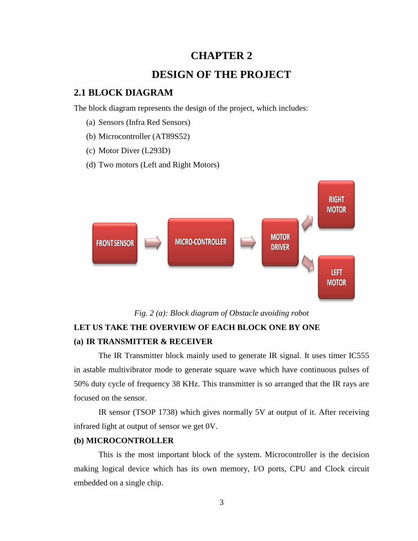
The block diagram represents the design of the project, which includes:
(a) Sensors (Infra Red Sensors)
(b) Microcontroller (AT89S52)
(c) Motor Diver (L293D)
(d) Two motors (Left and Right Motors)
Fig. 2 (a): Block diagram of Obstacle avoiding robot
LET US TAKE THE OVERVIEW OF EACH BLOCK ONE BY ONE
(a) IR TRANSMITTER & RECEIVER
The IR Transmitter block mainly used to generate IR signal. It uses timer IC555
in astable multivibrator mode to generate square wave which have continuous pulses of
50% duty cycle of frequency 38 KHz. This transmitter is so arranged that the IR rays are
focused on the sensor.
IR sensor (TSOP 1738) which gives normally 5V at output of it. After receiving
infrared light at output of sensor we get 0V.
(b) MICROCONTROLLER
This is the most important block of the system. Microcontroller is the decision
making logical device which has its own memory, I/O ports, CPU and Clock circuit
embedded on a single chip.
4
(c) L293D DRIVER
L293D is used as driver IC. Motors are connected to this IC. According to
program in µc it drives the left and right motor.
(d) MOTOR
DC motors are used to move the robot forward and backward. These motors are
run on 9V D.C. power supply.
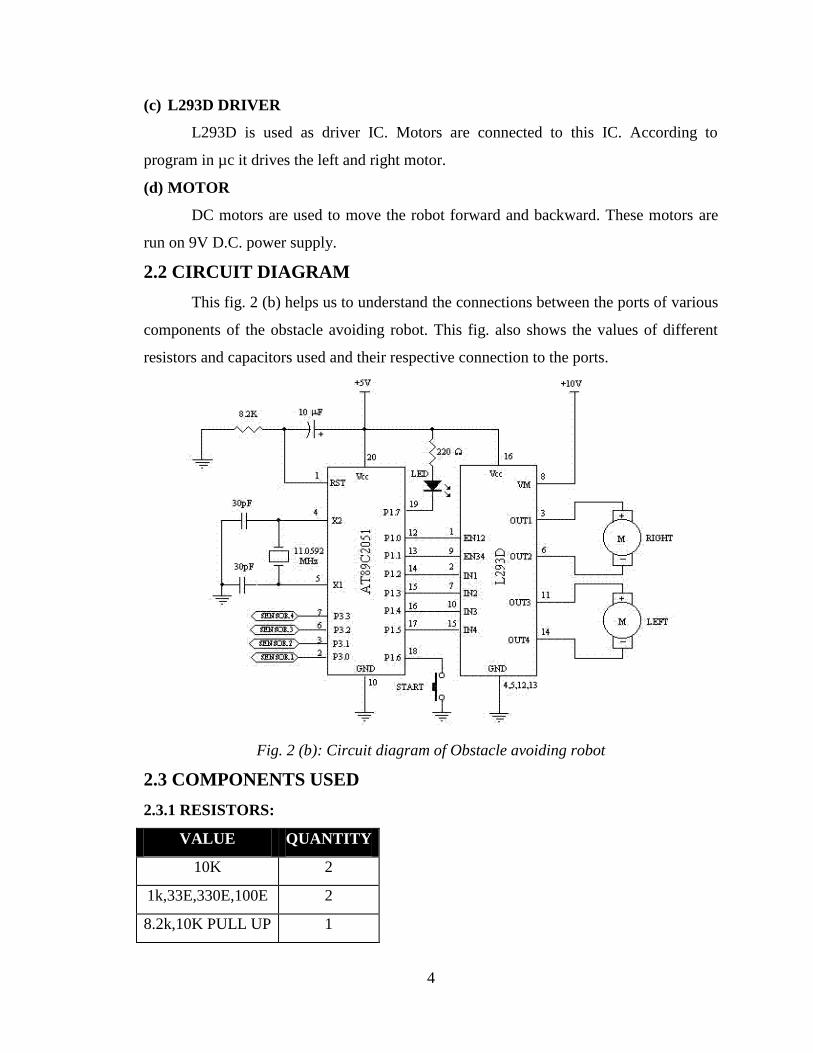
2.2 CIRCUIT DIAGRAM
This fig. 2 (b) helps us to understand the connections between the ports of various
components of the obstacle avoiding robot. This fig. also shows the values of different
resistors and capacitors used and their respective connection to the ports.
Fig. 2 (b): Circuit diagram of Obstacle avoiding robot
2.3 COMPONENTS USED
2.3.1 RESISTORS:
VALUE QUANTITY
10K 2
1k,33E,330E,100E 2
8.2k,10K PULL UP 1
5
2.3.2 CAPACITOR:
VALUE QUANTITY
0.1,10,4.7 1
22 P 2
2.3.3 OSCILLATORS:
VALUE QUANTITY
11.0592 MHz 1
2.3.4 ICs:
VALUE QUANTITY
89V51RD2 1
L293D,7805 1
2.3.5 MISCELLANEOUS:
COMPONENT QUANTITY
6V, 200 RPM DC MOTOR 2
ZENER DIODE, 5.6V 3
RESET SWITCH 1
6V DC BATTERY 2
CONNECTING WIRES -
2.4 PCB LAYOUT
INTRODUCTION:
A printed circuit board (PCB) mechanically supports and electrically connects
electronic components using conductive tracks, pads and other features etched from
copper sheets laminated onto a non-conductive substrate. PCBs can be single sided (one
copper layer), double sided (two copper layers) or multi-layer. Conductors on different
layers are connected with plated-through holes called vias. Advanced PCBs may contain
components - capacitors, resistors or active devices - embedded in the substrate.
6
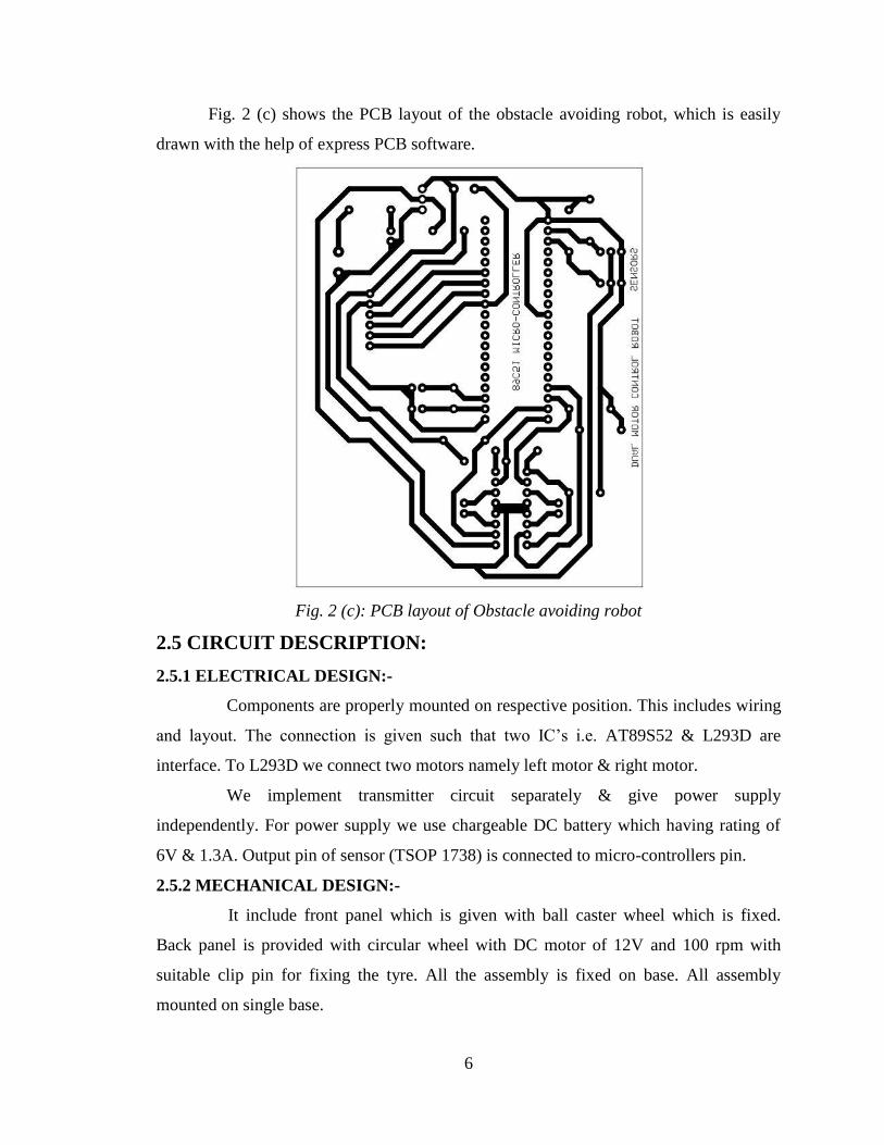
Fig. 2 (c) shows the PCB layout of the obstacle avoiding robot, which is easily
drawn with the help of express PCB software.
Fig. 2 (c): PCB layout of Obstacle avoiding robot
2.5 CIRCUIT DESCRIPTION:
2.5.1 ELECTRICAL DESIGN:-
Components are properly mounted on respective position. This includes wiring
and layout. The connection is given such that two IC‟s i.e. AT89S52 & L293D are
interface. To L293D we connect two motors namely left motor & right motor.
We implement transmitter circuit separately & give power supply
independently. For power supply we use chargeable DC battery which having rating of
6V & 1.3A. Output pin of sensor (TSOP 1738) is connected to micro-controllers pin.
2.5.2 MECHANICAL DESIGN:-
It include front panel which is given with ball caster wheel which is fixed.
Back panel is provided with circular wheel with DC motor of 12V and 100 rpm with
suitable clip pin for fixing the tyre. All the assembly is fixed on base. All assembly
mounted on single base.
7
2.6 ALGORITHM
The algorithm is the program written in the CPU of the microcontroller for the
proper execution of the project. This program is very simple and written in 8051
assembly language.
$mod51
org 0000h
s:
jnb p0.0,x
mov p2,#11110110b
sjmp s
x:
mov p2,#11111001b
sjmp s
end
The above written instructions are simply illustrates to move the robot forward, if
no obstacle is in front of robot. If the robot encounters any obstacle, then it will move
backwards and save the robot from collision.
2.7 PROBLEMS FACED
Although the concept & design of the project seemed perfect, there were some
problems faced while actual implementation:
2.7.1 GENERATION OF EXACT 38 KHZ FREQUENCY FROM IC 555 AT:-
Transmitter circuit Solution: Use variable resistor pot in astable multivibrator. Connect
IC 555‟s output pin to C.R.O. & measure frequency pulses generated by IC 555. By
varying the resistor pot we can adjust the frequency of output.
2.7.2 AVAILABILITY OF BURNER:
Solution: As burner kit is not easily available, so we have design & implement hardware
for burn the IC.
8
CHAPTER 3
TESTING
3.1 HARDWARE TESTING:-
(a) CONTINUITY TEST:-
First of all we checked the PCB that all the tracks are as per the design of PCB
and showing continuity with the help of multimeter and PCB layout.
(b) SHORT CIRCUIT TEST:-
Then we checked the PCB for any unwanted short circuits with the help of
multimeter and PCB layout.
(c) SOLDERING:-
In the next step, we soldered the required components and then checked that there
are no any unwanted shorts occurred due to soldering without putting IC's and keeping
power supply off.
(d) POWER SUPPLY TEST:-
In the next step, we put power supply on and checked whether required voltage is
appearing at the required voltage is appearing at the required points i.e. +Vcc and GND at
the respective points. We took care of not connecting IC's in the circuit while performing
this test.
(e) MICROCONTROLLER TEST:-
For testing the microcontroller, we wrote the square wave generation program for
generating square wave on each port pin. Then we fed the program in microcontroller and
checked the output with the help of CRO by connecting the microcontroller in the circuit.
We took care of not connecting any other IC in the circuit.
9
CHAPTER 4
SOFTWARES USED
4.1 EXPRESS PCB
INTRODUCTION: Express PCB proved to be a very handy & easy-to-use tool for
the PCB layout process. Many of its features were utilized leading to an accurate &
efficient design. It has Design Error Check & Electrical Rule Check tools which
proved to be helpful in the design. It is loaded with a huge component list that is
categorized in various libraries for giving simplicity. Placement of components is
also very easy & they can be rotated in 360⁰ to customize the design.
STEPS USED IN THE DESIGN:
(i) Select the components from the component manager dialog box.
(ii) Positioning the components to the desired location on your board.
(iii) Add the traces by clicking on the pin of a component and dragging the trace
to another pin.
(iv) Edit the layout is simple using standard commands such as Copy, Cut and
Paste. Rearrange the parts by dragging them with the mouse.
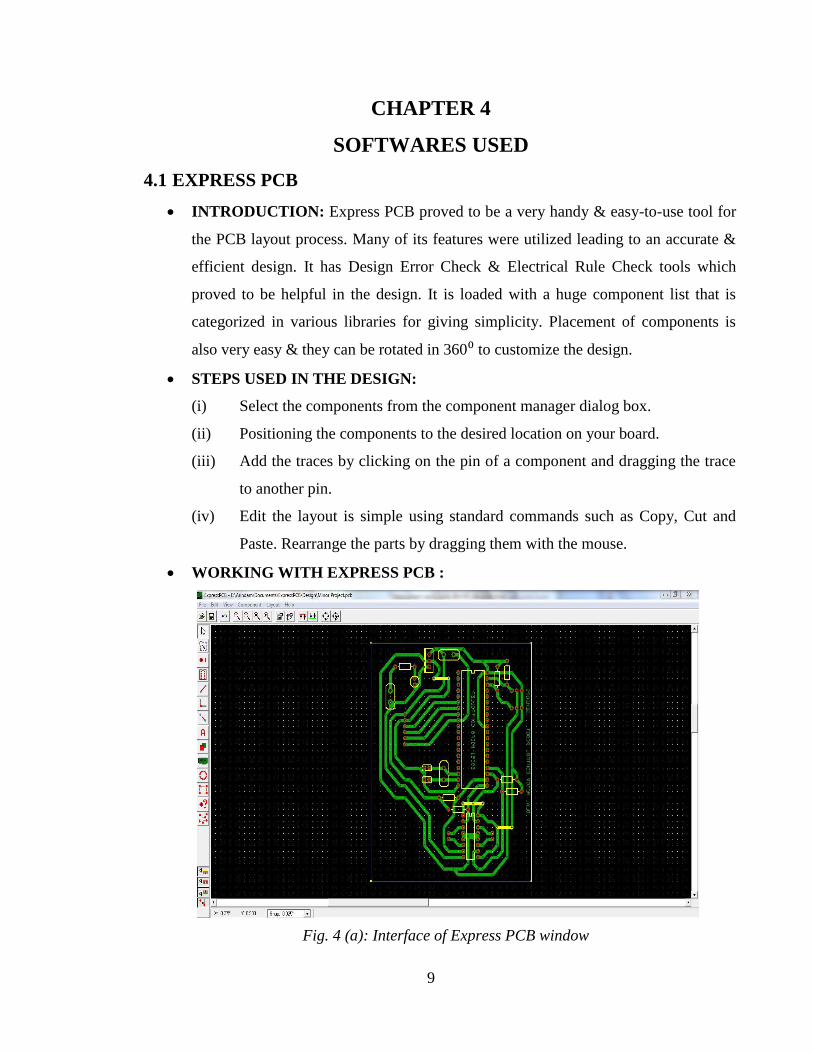
WORKING WITH EXPRESS PCB :
Fig. 4 (a): Interface of Express PCB window
10
4.2 TOPVIEW SIMULATOR
INTRODUCTION: Topview Simulator gives an excellent simulation
environment for the industry's most popular 8 bit Microcontroller family, MCS
8051. It gives required facilities to enable the system designers to start projects
right from the scratch and finish them with ease and confidence. It is the total
simulation solution giving many state of art features meeting the needs of the
designers possessing different levels of expertise.
STEPS USED IN THE DESIGN:
(i) When starting a new project, simply select the microcontroller you use
from the Device Database.
(ii) Top View Simulator sets all Compiler, Assembler, Linker, and Memory
options. It‟s device database is large which supports many ICs of the 8051
family.
(iii) Click on TEXT button from menu, name the project and write the
program.
(iv) A HEX file can be created with the help of Top View Simulator which is
required for burning onto chip. It has a powerful debugging tool which
detects most of the errors in the program.
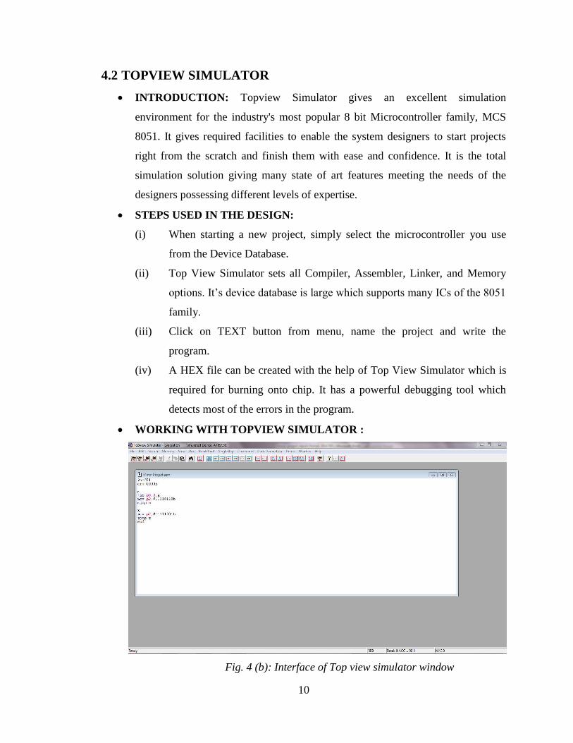
WORKING WITH TOPVIEW SIMULATOR :
Fig. 4 (b): Interface of Top view simulator window
11
4.3 PROG-ISP
INTRODUCTION: Prog-ISP is a PC tool for programming flash based
microcontrollers from PC or Laptop using a serial or Ethernet protocol while in the
target hardware. It has some excellent features like changeable baud rate; erase all
flash before programming, setting security bits etc. The HEX file created with the
help of Top View Simulator was selected through it for programming the
microcontroller.
STEPS USED IN THE DESIGN:
(i) Plug in USBasp to an available USB port in your PC and connect to the
Standard Kit. (Refer to Development Setup)
(ii) Run progisp.exe.
(iii) Select AT89S52 under “Select Chip”.
(iv) Load program file, click Menu, then File, goto Load Flash, select abc.hex.
(v) Click „Auto‟ button.
(vi) Done.
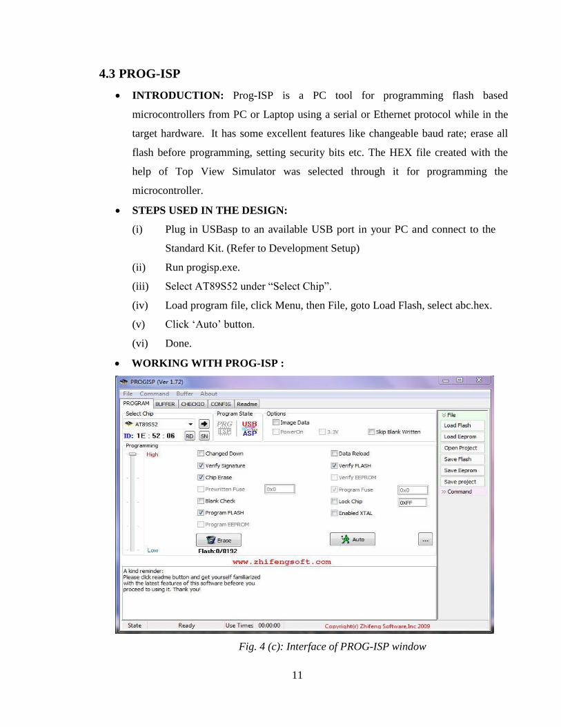
WORKING WITH PROG-ISP :
Fig. 4 (c): Interface of PROG-ISP window
12
CHAPTER 5
APPLICATIONS
5.1 OBSTACLE DETECTION FOR A MINING VEHICLE
Reliable obstacle detection is an essential element of an autonomous mining
vehicle system. An autonomous vehicle must be capable of detecting potentially
dangerous obstacles that would endanger the vehicle itself, other vehicles, personnel or
expensive site infrastructure while navigating through the mine. Autonomous vehicles
will not be deployed in the field alongside manned vehicles until robust obstacle
detection systems have been developed.
The development of robust obstacle detection systems for these vehicles is
difficult because of the relatively harsh conditions encountered in mining environments.
The operating environment could include rain, dust, mud, high humidity, diesel fumes
(small particles), extremes of temperature, severe vibration, extreme vehicle pitching and
rolling, and bright light sources (e.g. the sun).
5.2 DRIVERLESS VEHICLES RUNNING ALONG BEAMS
Behind obstacle detection as it stands today, and how it might fill the needs of
driverless vehicles running along beams. To replace the eyes and brains of a human
driver with equally good (or better) technological devices is very tricky. The human
mind´s ability to process sensory information is very advanced and complex. The
research going on today to make robots detect obstacles is very much based on how
insects do the same thing.
The sensors of the obstacle detection systems that are of interest to us are built on
different technologies. Those that are available to us today are:
1. Infrared sensors
2. Common radar
3. Microwave-based radar
4. Digital cameras
5. Laser
6. Combination of digital cameras and laser
13
The present invention provides a digital ultrasonic obstacle detection system for
vehicles, which can tune reference data, which is the basis for the determination of
whether an obstacle has been detected. This system executes a parking assist mode or a
tuning mode in response to a command from an external master. The system is
configured to store reflected wave signal data received from a sensor unit, in memory and
transmit the reflected wave signal data to the external master via vehicle communication,
at the time of executing the tuning mode.
5.3 OBSTACLE DETECTING SYSTEM FOR A MOTOR VEHICLE
An obstacle detecting system for a motor vehicle which is capable of detecting
not only the distance to an obstacle(s) existing in front of the motor vehicle and the width
thereof, but also its height to thereby allow a motor vehicle control to be effected more
appropriately with high reliability. The distance to the object and its width are detected
by a laser radar type distance detecting unit, while the distance to the object lying within
a window preset by a window setting device is also detected by a distance detecting
circuit of a stereoscopic video camera unit. An object size determining unit is provided
for selecting a window corresponding to a distance value detected by the stereoscopic
video camera unit and which coincides with a distance value calculated by the laser radar
type distance detecting unit, to thereby determine the size of the object on the basis of the
preset position of the selected window.
5.4 AUTONOMOUS CLEANING ROBOT
This invention relates to an obstacle detection system for an autonomous cleaning
robot. There is a long felt need for autonomous robotic cleaning devices for dusting,
mopping, vacuuming, and sweeping operations. Although technology exists for complex
robots which can, to some extent, "see" and "feel" their surroundings, the complexity,
expense and power requirements associated with these types of robotic subsystems render
them unsuitable for the consumer marketplace. It is therefore an object of this invention
to provide a robot obstacle detection system which is simple in design, low cost, accurate,
easy to implement, and easy to calibrate.

14
CHAPTER 6
FURTHER IMPROVEMENTS & SCOPE
6.1 ADDING A CAMERA:
If the current project is interfaced with a camera (e.g. a Webcam) robot can be driven
beyond line-of-sight & range becomes practically unlimited as networks have a very
large range.
6.2 USE AS A FIRE FIGHTING ROBOT:
By adding temperature sensor, water tank and making some changes in programming we
can use this robot as fire fighting robot.
15
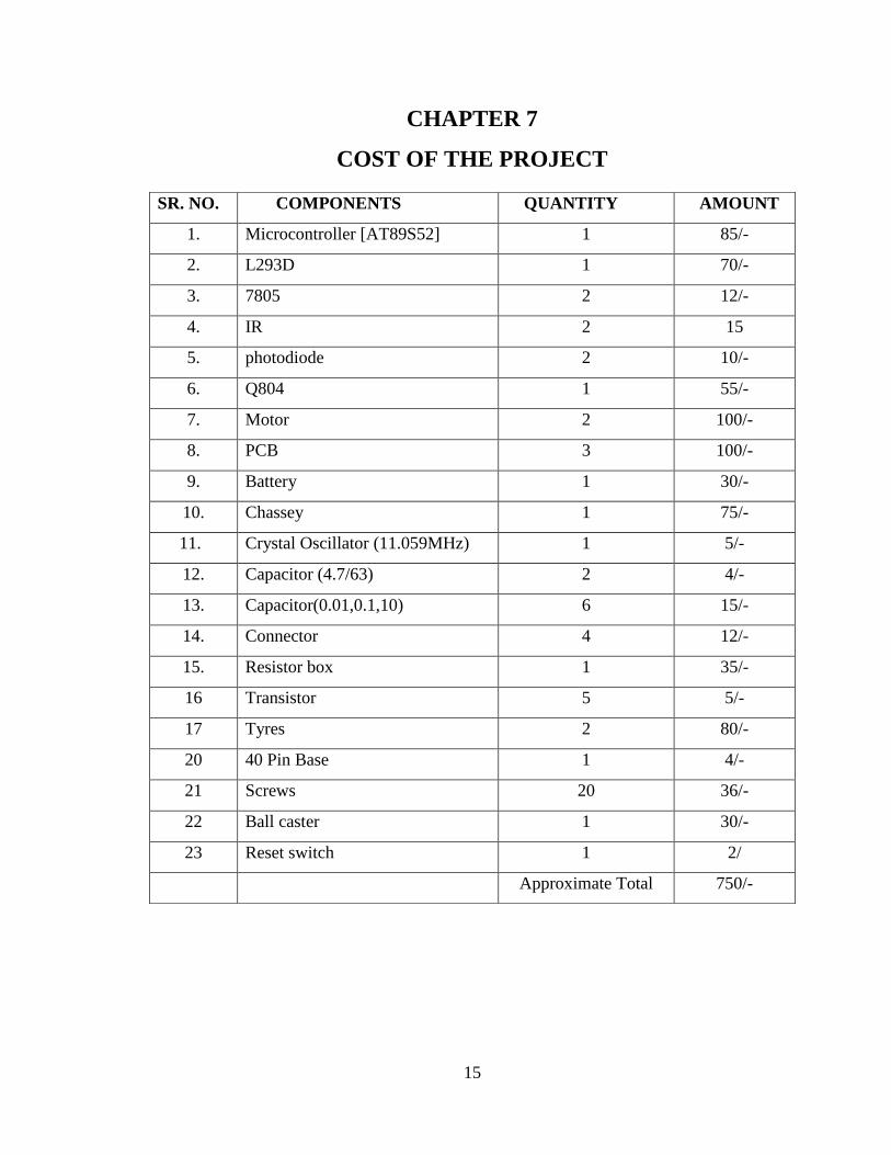
CHAPTER 7
COST OF THE PROJECT
SR. NO. COMPONENTS QUANTITY AMOUNT
1. Microcontroller [AT89S52] 1 85/-
2. L293D 1 70/-
3. 7805 2 12/-
4. IR 2 15
5. photodiode 2 10/-
6. Q804 1 55/-
7. Motor 2 100/-
8. PCB 3 100/-
9. Battery 1 30/-
10. Chassey 1 75/-
11. Crystal Oscillator (11.059MHz) 1 5/-
12. Capacitor (4.7/63) 2 4/-
13. Capacitor(0.01,0.1,10) 6 15/-
14. Connector 4 12/-
15. Resistor box 1 35/-
16 Transistor 5 5/-
17 Tyres 2 80/-
20 40 Pin Base 1 4/-
21 Screws 20 36/-
22 Ball caster 1 30/-
23 Reset switch 1 2/
Approximate Total 750/-

16
CHAPTER 8
BIBLIOGRAPHY
8.1 BOOKS CONCERNED:
The 8051 Microcontroller and embedded systems (Pearson Education) By - M.A.Mazidi.
8.2 INTERNET LINKS:
http://en.wikipedia.org/wiki/Robotics
http://www.8051projects.info/
http://www.instructabal.com/
http://www.alldatasheet.com/
http://www.datasheet4u.com/
http://www.datasheetcatalog.com/
http://www.frontline-electronics.com/html/simulator8031.htm
http://www.expresspcb.com/
http://en.wikipedia.org/wiki/Printed_circuit_board
oarobot.blogspot.com/
www.gie.com.my/download/um/mcu/8051standardkit.pdf