Embed Size (px)
Citation preview
LOVELY PROFESIONAL UNIVERSITY
Submitted as a part of course curriculum for
Minor PROJECT
Under the Guidance of
Ms. Swati Goel
Lecturer – LHSTLovely Professional University, Phagwara
Developed and submitted by
Shekhar (A3801A01)
(Bachelor of Computer Application)3nd year
As a part of 6th semester major project
ACKNOWLEDGEMENT
I take this opportunity to express my profound sense of gratitude and respect to all
those who helped me during this project.
First and foremost I also express my heartfelt thanks to Ms.swati Goel for giving
me an opportunity to undertake this project and providing me crucial feedback that
influenced me an opportunity to undertake the project work in this esteemed
concern. Without his guidance I have not been able to complete my work
successfully.
Finaaly I would like to extend my profound thanks to all my esteemed colleagues
and friends at college level.
- 2 -
CERTIFICATE OF ORIGINALITY
This is to certify that this project has been undertaken under my guidance as a part
of 6th semester trainin of BCA 3rd year from lovely professional university. This
project is original to the best of my knowledge.
he possesses good conduct and has successfully completed the training/project
work. I wish him grand success in his future life.
Date: Project Coordinator
01-08-2009 Ms. Swati Goel
- 3 -
PROJECT
ON
Scientific calculator
- 4 -
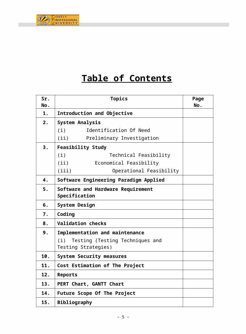
Table of Contents
Sr. No.
Topics Page No.
1. Introduction and Objective
2. System Analysis
(i) Identification Of Need
(ii) Preliminary Investigation
3. Feasibility Study
(i) Technical Feasibility
(ii) Economical Feasibility
(iii) Operational Feasibility
4. Software Engineering Paradigm Applied
5. Software and Hardware Requirement Specification
6. System Design
7. Coding
8. Validation checks
9. Implementation and maintenance
(i) Testing (Testing Techniques and Testing Strategies)
10. System Security measures
11. Cost Estimation of The Project
12. Reports
13. PERT Chart, GANTT Chart
14. Future Scope Of The Project
15. Bibliography
- 5 -
1. INTRODUCTION AND OBJECTIVE
INTRODUCTION OF THE PROJECT
I have made the scientific calculator in c graphics. I have made attempt to make all
the operations which an scientific calculator is consist of. There are certain fields like
addition, substraction, division, trigonometric functions, log, etc. calculator is use for
daily calculations which is consist of the all the airthemetic operations.
.
OBJECTIVE OF THE SYSTEM
The objectives of the new system are:
Greater speed of processing
Accurate calculation.
Faster speed of calculating the complex values.
Reduced calculation.
User friendly .
Designed system is used to reduce the calculation time.
- 6 -
2. SYSTEM ANALYSIS
(i) IDENTIFICATION OF NEED
(ii) PRELIMINARY INVESTIGATION
SYSTEM ANALYSIS
System analysis is an important activity that takes place when new
information system is being built or existing ones are changed. Its most crucial role
is in defining user requirements.
System analysis, often called business system analysis to emphasize its
business emphasis, is needed in the first instance to clearly identify what is the
possible and how a new system will work. This includes gathering the necessary
data and developing models for the new systems.
There are many constraints imposed on analyst and many people to satisfy. A
system analyst must spend a lot of time talking to users and finding out how they
use system.
Two of the steps are:-
Identification of need
Preliminary investigation
- 7 -
(i) Identification of need
Problems with the current system-
This software should remove all the problems generally faced in manual calculations.
Some of the problems are categories as follows:
1. calculations of large number of values is difficult.
2. time consumption is more for calculating.
3. complex calculation.
4. inaccurate results.
In order to cope up with the above-mentioned problems, this software has to be
designed and developed to computerize the calculation of the values.
We deal with large number of calculations in our daily life, so it is nessery to make a
software which can save our time.
(ii) Preliminary investigation
Preliminary investigation is one of the activities of system development life cycle. It is
the first step in the system development life cycle, which determines the feasibility of
the system. The purpose of preliminary investigation is to evaluate project requests.
Preliminary investigation is collecting the information that helps committee members
to evaluate the merits of the project request and make an informed judgment about
the feasibility of the proposed project.
- 8 -
Analysts working on the preliminary investigation should accomplish the
following objectives:
Clarify and understand the project requests.
Determine the size of the project.
Assess costs and benefits of alternative approaches.
Determine the technical and operational feasibility of alternative approaches.
Report the finding to management, with recommendations outlining the
acceptance or rejection of the proposal.
ABOUT THE CALCULATOR–
A scientific calculator is a type of electronic calculator, usually but not always handheld, designed to calculate problems in science (especially physics), engineering, and mathematics. They have almost completely replaced slide rules in almost all traditional applications, and are widely used in both education and professional settings.
In certain contexts such as higher education, scientific calculators have been superseded by graphing calculators, which offer a superset of scientific calculator functionality along with the ability to graph input data and write and store programs for the device. There is also some overlap with the financial calculator market.
Conducting the preliminary investigation
The data that the analysts collect during preliminary investigation are gathered
through these preliminary methods.
1.Reviewing organisation documents-The analysts conducting the investigation
first learn the organisation involved in, or affected by the project. Analysts can get
some details by examining organisation charts and studying written operating
procedures.
2.Gathering information by asking questions- Interviewing is the most commonly
used techniques in analysis. It is always necessary first to approach someone and
- 9 -
ask them what their problems are, and later to discuss with them the result of your
analysis.
.3.Questionnaires- Questionnaires provides an alternative to interviews for finding
out information about a system. Questionnaires are made up of questions about
information sought by analyst. The questionnaire is then send to the user, and the
analyst analyzes the replies.
4.Electronic data gathering- electronic communication systems are increasingly
being used to gather information. Thus it is possible to use electronic mail to
broadcast a question to a number of users in an organisation to obtain their
viewpoint on a particular issue.
5. Interviews- Interview allows the analysts to learn more about the nature of the
project request and reason of submitting it. Interviews should provide details that
further explain the project and show whether assistance is merited economically,
operationally or technically.
One of the most important points about interviewing is that what question you need
to ask.
It is often convenient to make a distinction between three kinds of question
that is
Open questions
Closed question
Probes
Open questions are general question that establish a persons view point on a
particular subject. Thus there might be a question such that
1. What do you think of calculator in your type of work?
2. How relevant is the calculator forecast to your activity?
- 10 -
3.Project Feasibility
(i) Technical feasibility
(ii) Operational feasibility
(iii) Economic feasibility
Feasibility study
Preliminary investigation examine project feasibility, the likelihood the system will be
useful to the organisation.
Feasibility is said to be determination of whether the project is worth doing or not.
The process followed in making this determination is called feasibility study. This
type of study determines if a project can and should be taken. Once it has been
determined that the project is feasible, the analysts can go ahead and prepare the
project specification which finalizes project requirements.
Different types of feasibility:
1. Technical feasibility
2. Operational feasibility
3. Economic feasibility
Technical feasibility
Technical feasibility is concerned with specifying equipment and software that will
successfully satisfy the user requirement.
The technical needs of the system may vary but might include:
The facility to respond with in time.
Accurate calculation.
Ability to solve complex equations with in no time.
- 11 -
.In technical feasibility, the configuration of the system is given more importance
than the actual make of the hardware.
The configuration should give the complete picture about the system requirements:
How many workstations are required?
How these units are interconnected so that they can operate and communicate
smoothly?
What speeds of input and output should be achieved at particular quality of printing?
Specific software and hardware products can then be evaluated keeping in view with
the logical needs.
Economical feasibility
Economic analysis or cost/benefit analysis is most frequently used technique for
evaluating the effectiveness of a proposed system. It is procedure to determine the
benefits and savings that are expected from the proposed system and compare them
with costs. If the benefit outweigh the costs, a decision is taken to design and
implement the system. Otherwise, further justification or alternative in the proposed
system will have to be made if it is to have a chance of being approved. This is an on
going effort that improves in accuracy at each phase of system life cycle.
Operational feasibility
Operational feasibility covers two aspects. One technical performance aspect and
the other is the acceptance within the organization. The points to be considered are:
What changes will be brought with the system?
What organizational are disturbed?
What new skills will be required? Do the existing staff members have these skills? If
not, can they be trained in the due course of time?
- 12 -
Operational feasibility determines how the proposed system will fit in with the current
operations and what, if any, job reconstructing and retraining may be needed to
implement the system. The evaluation must then determine the general attitude and
skills of existing personnel and whether any such reconstructing of jobs will be
acceptable to the current users.
4. Software engineering paradigm applied
Software engineering paradigm applied
To solve actual problems in an industry setting, a software engineer or a team of
Engineers must incorporate a development strategy that encompasses the process,
methods, and tools layers. This strategy is often referred to as a process model or a
software-engineering paradigm.
A process model or a software engineering is chosen based on the nature of the
project and application, the methods and tools to be used, and the controls and
deliverables that are required.
There are so many software paradigms: -
Linear sequential modal ( water fall modal)-
Some times called the classical life cycle or the water fall model,
the linear sequential model suggests a systematic, sequential approach to
software development that begins at the system level and progresses through
analysis, design, coding, testing and support.
Prototyping modal -
Prototyping paradigm begins with requirements gathering.
Developer and the customer meet and define the overall objective of the
- 13 -
software, identify whatever requirements, and outlines areas where
furtherdefinition is mandatory. A quick design then occurs. The quick design
leads to the construction of prototype. The prototype is evaluated by the
customer/user and use to refine requirement of the software to be developed.
The RAD modal.
Rapid application development modal is a high-speed adaptation of the linear
sequential model in which rapid development is achieved by using component-based
construction.
In my project linear sequential modal is used (waterfall modal) involved steps
given below: -
System /information engineering and modeling. Because software is always
part of a larger system (or business), work begins by establishing requirements for
all system elements and then allocating some subset of these requirements to
software. This system view is essential when software must interact with other
elements such as hardware, people, and databases. System engineering and
analysis encompass requirements gathering at the system level with a small amount
of top level design and analysis. Information engineering encompasses requirements
gathering at the strategic business level and at the business area level.
Software requirements analysis. The requirements gathering process is
intensified and focused specifically on software. To understand the nature of the
program(s) to be built, software engineer (analyst) must understand the information
domain for the software, as well as required function, behavior, performance, and
interface. Requirements for both the system and the software are documented and
reviewed with the customer.
- 14 -
Design. Software design is actually a multi step process that focuses on four distinct
attributes of a program: data structure, software architecture, interface
representations, and procedural detail. The design process translates requirements
into a representation of the software that can be assessed for quality before coding
begins. Like requirements, the design is documented and becomes part of the
software configuration.
Code generation. The design must be translated into a machine code. The code
Generation step performs thin task. If design is performed in a detailed manner, code
generation can be accomplished mechanistically.
Testing. Once code has been generated, program testing begins. The testing
process focuses on the logical internals of the software, ensuring that all statements
have been tested, and on the functional externals; that is, conducting tests to
uncover errors and ensure that defined input will produce actual results that agree
with required results.
Support. Software will undoubtedly undergo changes after it is delivered to the
Customer. Changes will occur because errors have been encountered, because the
software must be adapted to accommodate changes in its external environment, or
because the customer requires functional or performance enhancements. Software
support/maintenance reapplies each of the preceding phases to an existing program
rather than a new one.
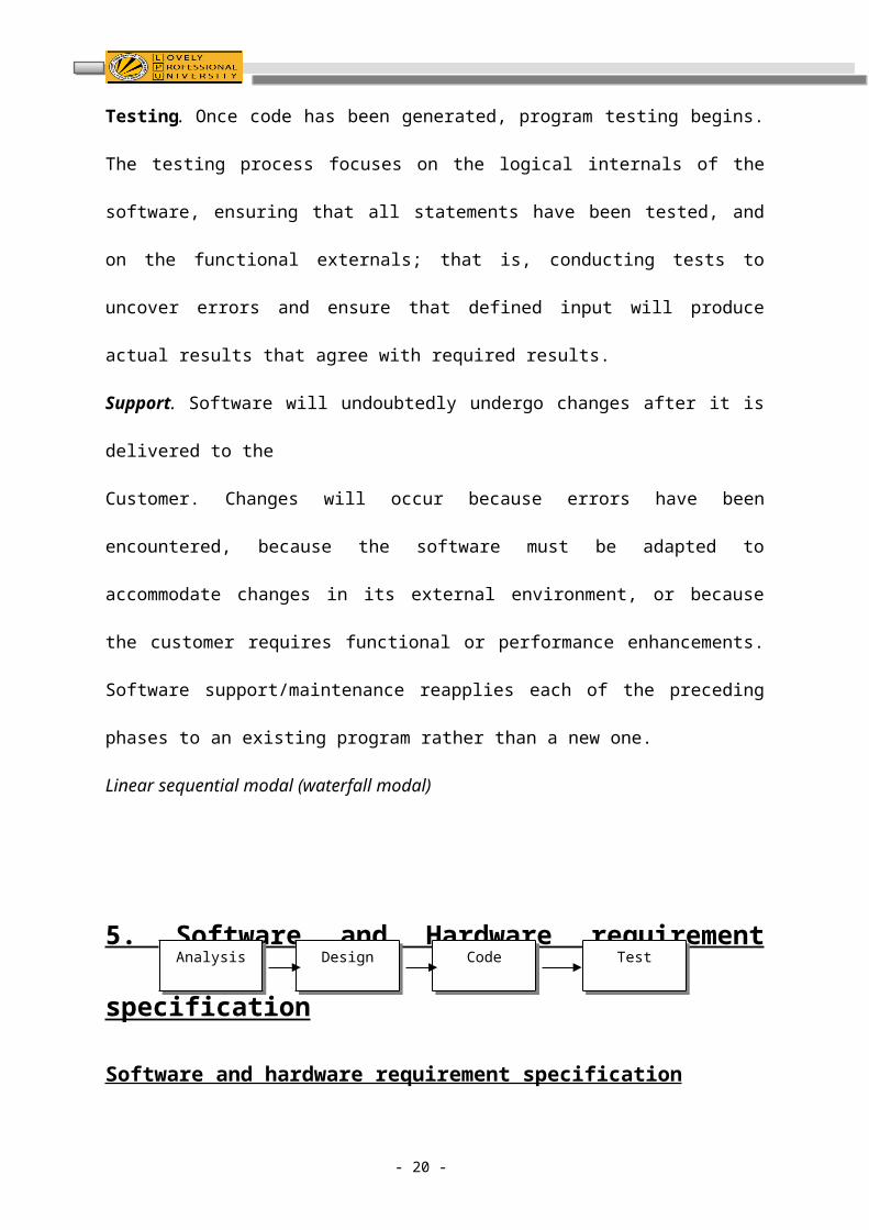
Linear sequential modal (waterfall modal)
5. Software and Hardware requirement specification
Software and hardware requirement specification
- 15 -
Design Code Test Analysis
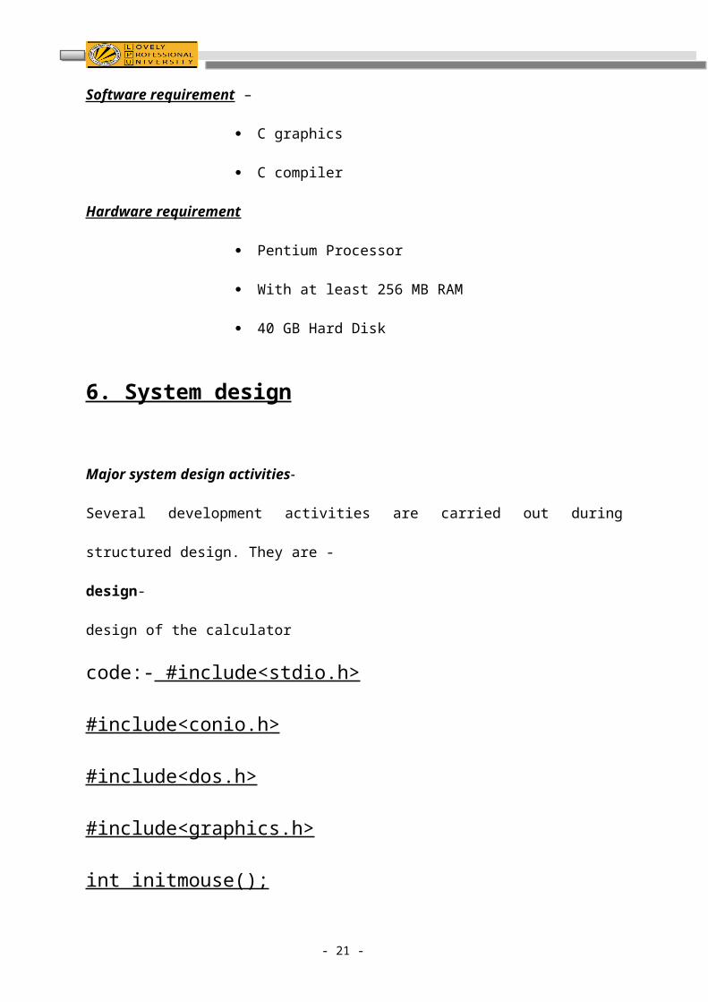
Software requirement –
C graphics
C compiler
Hardware requirement
Pentium Processor
With at least 256 MB RAM
40 GB Hard Disk
6. System design
Major system design activities-
Several development activities are carried out during structured design. They are -
design-
design of the calculator
code:- #include<stdio.h>
#include<conio.h>
#include<dos.h>
#include<graphics.h>
int initmouse();
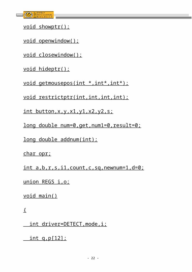
void showptr();
void openwindow();
void closewindow();
void hideptr();
- 16 -
void getmousepos(int *,int*,int*);
void restrictptr(int,int,int,int);
int button,x,y,x1,y1,x2,y2,s;
long double num=0,get,num1=0,result=0;
long double addnum(int);
char opr;
int a,b,r,s,i1,count,c,sq,newnum=1,d=0;
union REGS i,o;
void main()
{
int driver=DETECT,mode,i;
int q,p[12];
char input;
char *inpu[4][4]={"1","2","3","4",
"5","6","7","8",
"9","0","+","-" ,
"*","/","clr","="};
char inp[4][4]={'1','2','3','4',
'5','6','7','8',
- 17 -
'9','0','+','-' ,
'*','/','l','='};
initgraph(&driver,&mode,"c:\\tc\\bgi");
for(i=0;i<=100;i=i+1)
{
setcolor(9);
//clearviewport();
circle(50,0+i,10);
delay(3);
}
for(i=0;i<=50;i=i+1)
{
//clearviewport();
circle(50+i,100-i,10);
delay(3);
}
for(i=0;i<=50;i=i+1)
{
- 18 -
//clearviewport();
circle(100+i,50+i,10);
delay(3);
}
for(i=0;i<=100;i=i+1)
{
//clearviewport();
circle(150,100-i,10);
delay(3);
}
for(i=0;i<=100;i=i+1)
{
setcolor(6);
//clearviewport();
circle(200,0+i,10);
delay(3);
}
for(i=0;i<=100;i=i+1)
{
- 19 -
//clearviewport();
circle(200+i,0,10);
delay(3);
}
for(i=0;i<=100;i=i+1)
{
//clearviewport();
circle(200+i,50,10);
delay(3);
}
for(i=0;i<=100;i=i+1)
{
//clearviewport();
circle(200+i,100,10);
delay(3);
}
for(i=0;i<=100;i=i+1)
{
setcolor(2);
- 20 -
//clearviewport();
circle(350,0+i,10);
delay(3);
}
for(i=0;i<=100;i=i+1)
{
//clearviewport();
circle(350+i,100,10);
delay(3);
}
//creating c
for(i=0;i<=100;i=i+1)
{
setcolor(10);
//clearviewport();
circle(100,150+i,10);
delay(3);
}
settextstyle(0,0,0);
- 21 -
for(i=0;i<=100;i=i+1)
{
//clearviewport();
circle(100+i,150,10);
delay(3);
}
for(i=0;i<=100;i=i+1)
{
//clearviewport();
circle(100+i,250,10);
delay(3);
}
//creating o
for(i=0;i<=100;i=i+1)
{
setcolor(5);
//clearviewport();
circle(250,150+i,10);
delay(3);
- 22 -
}
for(i=0;i<=100;i=i+1)
{
//clearviewport();
circle(250+i,250,10);
delay(3);
}
for(i=0;i<=100;i=i+1)
{
//clearviewport();
circle(250+i,150,10);
delay(3);
}
for(i=0;i<=100;i=i+1)
{
//clearviewport();
circle(350,250-i,10);
delay(3);
}
- 23 -
//creating m
for(i=0;i<=100;i=i+1)
{
setcolor(1
);
//clearviewport();
circle(400,150+i,10);
delay(3);
}
for(i=0;i<=50;i=i+1)
{
//clearviewport();
circle(400+i,150+i,10);
delay(3);
}
for(i=0;i<=50;i=i+1)
{
//clearviewport();
circle(450+i,200-i,10);
- 24 -
delay(3);
}
for(i=0;i<=100;i=i+1)
{
//clearviewport();
circle(500,150+i,10);
delay(3);
}
//creating e
for(i=0;i<=100;i=i+1)
{
setcolor(12);
//clearviewport();
circle(550,150+i,10);
delay(3);
}
for(i=0;i<=100;i=i+1)
{
//clearviewport();
- 25 -
circle(550+i,150,10);
delay(3);
}
for(i=0;i<=100;i=i+1)
{
//clearviewport();
circle(550+i,250,10);
delay(3);
}
for(i=0;i<=100;i=i+1)
{
//clearviewport();
circle(550+i,200,10);
delay(3);
}
if(initmouse()==0)
{
printf("not");
- 26 -
getch();
exit(0);
}
openwindow();
getch();
cleardevice();
setfillstyle(CLOSE_DOT_FILL,10);
bar(260,82,450,320);
bar(430,70,450,320);
setfillstyle(1,GREEN);
bar(236,82,432,300);
setcolor(GREEN);
rectangle(238,50,430,80);
rectangle(237,49,431,81);
rectangle(236,48,432,82);
c=240;
d=100;
s=0;
for(a=0;a<4;a++)
- 27 -
{
c=240;
for(b=0;b<4;b++)
{
setfillstyle(1,RED);
bar(c,d,c+40,d+40);
setcolor(YELLOW);
outtextxy(c+10,d+14,inpu[a][b]);
c+=50;
}
d+=50;
}
showptr();
num=0;
gotoxy(36,5);
printf("%18.1Lf",num);
count=0;
while(!kbhit())
{
- 28 -
outtextxy(30,20,"Press any key to exit..");
i1=0;
c=240;
d=100;
rectangle(0,0,638,478);
getmousepos(&button,&x,&y);
for(a=0;a<4;a++)
{
c=240;
for(b=0;b<4;b++)
{
if((x>=c&&x<=c+40)&&(y>=d&&y<=d+40))
{
if((button&1)==1)
{
while((button&1)==1)
{
setcolor(11);
rectangle(c,d,c+40,d+40);
- 29 -
rectangle(c-1,d-1,c+41,d+41);
rectangle(c-2,d-2,c+42,d+42);
break;
}
delay(100);
setcolor(GREEN);
rectangle(c,d,c+40,d+40);
rectangle(c-1,d-1,c+41,d+41);
rectangle(c-2,d-2,c+42,d+42);
input=inp[a][b];
switch(input)
{
case '1':
get=addnum(1);
gotoxy(36,5);
printf("%18.1Lf",get);
break;
case '2':
get=addnum(2);
- 30 -
gotoxy(36,5);
printf("%18.1Lf",get);
break;
case '3':
get=addnum(3);
gotoxy(36,5);
printf("%18.1Lf",get);
break;
case '4':
get=addnum(4);
gotoxy(36,5);
printf("%18.1Lf",get);
break;
case '5':
get=addnum(5);
gotoxy(36,5);
printf("%18.1Lf",get);
break;
case '6':
- 31 -
get=addnum(6);
gotoxy(36,5);
printf("%18.1Lf",get);
break;
case '7':
get=addnum(7);
gotoxy(36,5);
printf("%18.1Lf",get);
break;
case '8':
get=addnum(8);
gotoxy(36,5);
printf("%18.1Lf",get);
break;
case '9':
get=addnum(9);
gotoxy(36,5);
printf("%18.1Lf",get);
break;
- 32 -
case '0':
get=addnum(0);
gotoxy(36,5);
printf("%18.1Lf",get);
break;
case '+':
num1=num;
num=0;
opr='+';
gotoxy(36,5);
printf("%18.1Lf",num);
break;
case '-':
num1=num;
num=0;
opr='-';
gotoxy(36,5);
printf("%18.1Lf",num);
break;
- 33 -
case '*':
num1=num;
num=0;
opr='*';
gotoxy(36,5);
printf("%18.1Lf",num);
break;
case '/':
num1=num;
num=0;
opr='/';
gotoxy(36,5);
printf("%18.1Lf",num);
break;
case 'l':
num=0;
num1=0;
result=0;
count=0;
- 34 -
gotoxy(36,5);
printf("%18.1Lf",num);
break;
case '=':
switch(opr)
{
case '+':
if(count<1)
{
result=num+num1;
}
else
{
result=result+num;
}
gotoxy(36,5);
printf("%18.1Lf",result);
count+=1;
break;
- 35 -
case '-':
if(count<1)
{
result=num1-num;
}
else
{
result=result-num;
}
gotoxy(36,5);
printf("%18.1Lf",result);
count+=1;
break;
case '*':
if(count<1)
{
result=num1*num;
}
else
- 36 -
{
result=result*num;
}
gotoxy(36,5);
printf("%18.1Lf",result);
count+=1;
break;
case '/':
if(count<1)
{
result=num1/num;
}
else
{
result=result/num;
}
gotoxy(36,5);
printf("%18.1Lf",result);
count+=1;
- 37 -
break;
}
}
}
}
c+=50;
}
d+=50;
}
setcolor(YELLOW);
delay(150);
}
getch();
closewindow();
getch();
}
long double addnum(int getnum)
{
num=num*10+getnum;
- 38 -
return(num);
}
int initmouse()
{
i.x.ax=0;
int86(0x33,&i,&o);
return(o.x.ax);
}
void showptr()
{
i.x.ax=1;
int86(0x33,&i,&o);
}
void hideptr()
{
i.x.ax=2;
int86(0x33,&i,&o);
}
void restrictptr(int x1,int y1,int x2,int y2)
- 39 -
{
i.x.ax=7;
o.x.cx=x1;
o.x.dx=x2;
int86(0x33,&i,&o);
i.x.ax=8;
o.x.cx=y1;
o.x.dx=y2;
int86(0x33,&i,&o);
}
void getmousepos(int *button,int *x,int *y)
{
i.x.ax=3;
int86(0x33,&i,&o);
*button=o.x.bx;
*x=o.x.cx;
*y=o.x.dx;
}
void openwindow()
- 40 -
{
int aa,bb,cc,dd,maxx,maxy,i=10;
maxx=getmaxx();
maxy=getmaxy();
rectangle(0,0,maxx,maxy);
aa=250;
bb=400;
cc=260;
for(dd=250;dd<350;dd+=20)
{
setfillstyle(1,2);
bar(dd,bb,cc,bb+10);
cc+=20;
}
aa=250;
bb=400;
cc=260;
while(!kbhit())
{
- 41 -
setcolor(i);
if((aa==350)&&(cc==360))
{
aa=250;
cc=260;
break;
}
else
{
setcolor(10);
rectangle(aa,bb,cc,bb+10);
rectangle(aa-1,bb-1,cc+1,bb+11);
}
delay(300);
setcolor(BLACK);
rectangle(aa,bb,cc,bb+10);
rectangle(aa-1,bb-1,cc+1,bb+11);
aa+=20;
- 42 -
cc+=20;
}
}
void closewindow()
{
int i,j,k;
cleardevice();
rectangle(0,0,638,478);
k=0;
while(!kbhit())
{
setcolor(k);
settextstyle(5,0,8);
outtextxy(100,200,"THANK YOU");
line(90,300,600,300);
delay(200);
k++;
}
- 43 -
}
7 CONTEXT LEVEL DIAGRAM FOR BUSINESS MANAGEMENTMENT SYSTEM
- 44 -
Screen of calculator Division
Addition
Substraction
SEE FEEDBACK Trigonometric functions
Tangent
Sin Cos Log
Data Flow Diagram for the software system
wrong values Right values
- 45 -
Accepted
Screen User
Performing the calculation eg
2+2=4
Reenter the values Result
Trigonometric functions
Addition
Airthmatic functions
Cos
8. Validation checks
Various validation checks are used–
For example-
Valid data should be entered in the calculator.
Like numeric data should be entered for the numeric field.
9. Implementation and Maintenance
(i) Testing (testing techniques and testing strategies)
Software is tested from two different perspectives:
Internal program logic is exercised using “white box” test case design techniques.
Software requirements are exercised using “black box” test case design
techniques.
- 46 -
substraction
Division
Multiply Sin
In both cases, the intend is to find the maximum number of errors with the minimum
amount of effort and time.
White box testing-
Using white box testing methods, the software engineer can derive test cases that
1. Guarantee that all independent paths within a module have been
exercised at least once.
During testing project is tested in various ways all the different paths are
tested. System is checked for all situations, which can occur.
Exercise all logical decisions on their true and false side.
.
2. Execute all loops at their boundaries and within their operational bounds.
3. Exercise internal data structures to ensure their validity.
Each of these reasons provides an argument for conducting white box test.
Black box testing-
Black box testing focuses on the functional requirements of the
software that is black box testing enable a software engineer to derive sets of input
conditions that will fully exercise all functional requirements for a program. Black box
testing is a complementary approach that is likely to uncover a different class of
errors. Black box testing attempts to find errors in the following categories-
1. Incorrect or missing functions.
System is checked for all the function defined in the coding are working
properly.
2. Errors in data structures or external data base access.
System is checked that at the time of running the software all the
functions are available and working properly.
- 47 -
10. System security measures
No security mesures
11. Cost estimation of the project
Estimating involves evaluating the amount and complexity of work to be done in
each task. This information is used to determine the resources needed to complete
the work. Estimates will depend on the type of work carried out in the task. Most
software estimates take into account the organisation experience related to the type
of task.
This can be where:
Existing software is used.
Previous experience exists.
Similar experience exists.
Totally new development.
Approach to software cost estimation-
1. Decomposition techniques take a “divide and conquer” approach to software
project estimation.
2. Empirical method can be used to complement decomposition technique and offer
a potentially valuable estimation approach in their own right.
3. Automated estimation tools implement one or more decomposition techniques or
empirical models.
Each of above software cost estimation options is only good as historical data used
to seed the estimate.
In my project I have used empirical estimation model as COCOMO MODEL for
software cost estimation.
- 48 -
COCOMO Model- COnstructive COst Model is one of the most widely used models
in the industry. COCOMO II is the hierarchy of estimation models. The COCOMO II
application composition model uses object points which is an indirect software
measure that is computed using counts of the number of
1. Screens(at user interface)
2. Reports, and
3. Components likely to be required to build the application.
12. Reports
No reports .
13. Pert chart
Program evaluation and review technique (pert) is a project scheduling method that
is applied to software development.
Pert provide quantitative tool that allow the software planner to-
Determine the critical path-the chain of tasks that determines the duration of the
project;
Establish “most likely” time estimates for individual tasks by applying statistical
models; and
Calculate “boundary times” that defines a time “window” for a particular task.
Pert chart for project-
- 49 -
Preliminary Investigation
User Manual
TestingCodingDesignAnalysis
Data collection
1
2
42
52
6 7 8
14. FUTURE SCOPE OF THE APPLICATION
Modern scientific calculators generally have many more features than a standard four or five-function calculator, and the feature set differs between manufacturers and models; however, the defining features of a scientific calculator include:
logarithmic functions, using both base 10 and base e trigonometric functions (some including hyperbolic trigonometry) exponential functions and roots beyond the square root quick access to constants such as pi and e
In addition, high-end scientific calculators will include:
hexadecimal , binary, and octal calculations, including basic Boolean math complex numbers fractions statistics and probability calculations programmability — see Programmable calculator equation solving calculus conversion of units physical constants
15. Bibliography
1. C graphics.
2. C compiler.
3. Software Engineering .
- 50 -