Embed Size (px)
Citation preview
Minneapolis Duct Blaster®
Operation Manual
(Series B Systems)
The ENERGYCONSERVATORYDIAGNOSTIC TOOLS TO MEASURE BUILDING PERFORMANCE
Minneapolis Duct Blaster ®
Operation Manual
(Series B Systems)
The Energy Conservatory2801 21st Ave. S., Suite 160Minneapolis, MN 55407(612) 827-1117 (Ph)(612) 827-1051 (Fax)www.energyconservatory.comemail: [email protected]
Minneapolis Duct Blaster and TrueFlow Air Handler Flow Meter are registered trademarks of The EnergyConservatory, Inc.. Minneapolis Blower Door, TECBLAST, Duct Mask and Automated Performance Testing(APT) System are trademarks of The Energy Conservatory, Inc.
Windows and Microsoft Word are registered trademarks of Microsoft Corporation.
Manual Edition: November 2003.© 2003 by The Energy Conservatory. All rights reserved.
ENERGY CONSERVATORY WARRANTY
EXPRESS LIMITED WARRANTY:
Seller warrants that this product, under normal use and service as described in the operator’s manual, shall be free from defects inworkmanship and material for a period of 24 months, or such shorter length of time as may be specified in the operator’s manual, from thedate of shipment to the Customer.
LIMITATION OF WARRANTY AND LIABILITY:
This limited warranty set forth above is subject to the following exclusions:
a) With respect to any repair services rendered, Seller warrants that the parts repaired or replaced will be free from defects inworkmanship and material, under normal use, for a period of 90 days from the date of shipment to the Purchaser.
b) Seller does not provide any warranty on finished goods manufactured by others. Only the original manufacturer’s warranty applies.c) Unless specifically authorized in a separate writing, Seller makes no warranty with respect to, and shall have no liability in
connection with, any goods which are incorporated into other products or equipment by the Purchaser.d) All products returned under warranty shall be at the Purchaser’s risk of loss. The Purchaser is responsible for all shipping charges to
return the product to The Energy Conservatory. The Energy Conservatory will be responsible for return standard ground shippingcharges. The Customer may request and pay for the added cost of expedited return shipping.
The foregoing warranty is in lieu of all other warranties and is subject to the conditions and limitations stated herein. No other express orimplied warranty IS PROVIDED, AND THE SELLER DISCLAIMS ANY IMPLIED WARRANTY OF FITNESS for particular purpose ormerchantability.
The exclusive remedy of the purchaser FOR ANY BREACH OF WARRANTY shall be the return of the product to the factory ordesignated location for repair or replacement, or, at the option of The Energy Conservatory, refund of the purchase price.
The Energy Conservatory’s maximum liability for any and all losses, injuries or damages (regardless of whether such claims are based oncontract, negligence, strict liability or other tort) shall be the purchase price paid for the products. In no event shall the Seller be liable forany special, incidental or consequential damages. The Energy Conservatory shall not be responsible for installation, dismantling, reassemblyor reinstallation costs or charges. No action, regardless of form, may be brought against the Seller more than one year after the cause ofaction has accrued.
The Customer is deemed to have accepted the terms of this Limitation of Warranty and Liability, which contains the complete and exclusivelimited warranty of the Seller. This Limitation of Warranty and Liability may not be amended or modified, nor may any of its terms bewaived except by a writing signed by an authorized representative of the Seller.
TO ARRANGE A REPAIR: Please call The Energy Conservatory at 612-827-1117 before sending any product back for repair or to inquireabout warranty coverage. All products returned for repair should include the reason for repair, a return shipping address, name and phonenumber of a contact person concerning this repair, and the purchase date of the equipment.
Table of Contents
Safety Information 1Equipment Safety Instructions 1
Other Important Safety Instructions 1
Chapter 1 Introduction to the Minneapolis Duct Blaster® 2
Chapter 2 Duct Leakage Basics 32.1 Why Is Duct Leakage Important? 3
2.2 Where Does Duct Leakage Occur? 3
2.3 How Much Can Energy Bills Be Reduced By Sealing Duct Leaks? 4
2.4 Duct Leakage to the Outside 4
2.5 Duct Leakage to the Inside 5
Chapter 3 System Components 63.1 Duct Blaster Fan 6
3.1.a Determining Fan Flow and Using the Flow Rings: 7
3.2 Test Instrumentation (Pressure and Fan Flow Gauges) 8
3.3 Fan Speed Controller 8
3.4 Flexible Extension Duct 9
3.5 The Flow Conditioner 9
3.6 Duct Blaster Carrying Case 10
3.7 TECBLAST Duct Airtightness Test Software (Optional) 10 3.7.a TECBLAST Features: 10
Chapter 4 Prepare the Duct System and Building for Testing 11
Chapter 5 Setting Up the Duct Blaster for Pressurization Testing 125.1 Where to Install the Duct Blaster System? 12
5.2 Connecting the Duct Blaster to the Duct System 13 5.2.a Installing at a Central Return: 13 5.2.b Installing at the Air Handler Cabinet: 14
5.3 The Gauge Mounting Board 15
5.4 Gauge Tubing Connections for Pressurization Testing 15 5.4.a DG-700: 15 5.4.b DG-3: 16
5.5 Selecting a Location to Measure Duct System Pressure 16 5.5 a Insert the Pressure Probe: 17
5.6 Tubing and Electrical Connections to the Fan 17 5.6.a Connect Red Tubing to the Fan: 17 5.6.b Electrical Connections: 17
Chapter 6 Conducting a Total Leakage Pressurization Test 186.1 Final Preparations (Open a Door or Window to the Outside) 19
6.2 Choosing the Test Pressure and Number of Test Readings 19 6.2.a Test Pressure: 19 6.2.b Number of Test Readings: 19
6.3 Total Leakage Test Procedures Using the DG-700 20
6.4 Total Leakage Test Procedures Using the DG-3 23
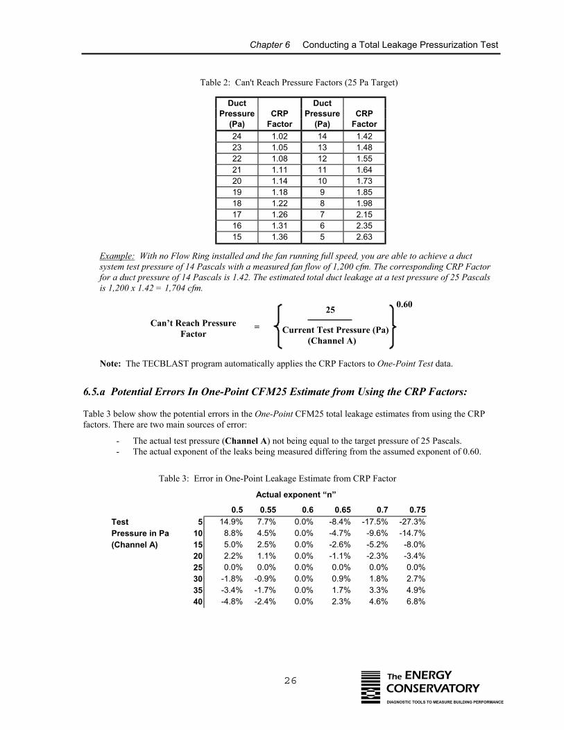
6.5 Using the Can’t Reach Pressure Factors (One-Point Tests) 25 6.5.a Potential Errors In One-Point CFM25 Estimate from Using the CRP Factors: 26
6.6 Unable to Reach a Target Building Pressure During a Multi-Point Test? 27
6.7 Before Leaving the Building 27
Chapter 7 Conducting a Leakage to Outside Pressurization Test 287.1 Final Preparations (Set Up Blower Door in Building) 29
7.1.a Building Pressure Measurements: 29
7.2 Choose the Test Pressure 30
7.3 Leakage to Outside Test Procedures Using the DG-700 30
7.4 Leakage to Outside Test Procedures Using the DG-3 32
7.5 What If You Can Not Pressurize the Building to the Test Pressure with the Blower Door Fan? 33
7.6 What If You Can Not Pressurize the Duct System to the Same Pressure as the Building with the Duct Blaster Fan? 34
7.7 Before Leaving the Building 35
Chapter 8 Test Results 368.1 Basic Duct Airtightness Test Results 36
8.1.a Duct Leakage at 25 Pascals: 36 8.1.b Normalizing Duct Leakage for the Size of the HVAC System and Building: 37 8.1.c Leakage Areas: 38
8.2 Additional Test Result Options (requires use of TECBLAST software) 38 8.2.a Estimated System Efficiency Losses: 38 8.2.b Duct Leakage Curve: 39
Chapter 9 Setting Up the Duct Blaster for Depressurization Testing 409.1 Installing the Flow Conditioner and Flow Ring 40
9.2 Where to Install the Duct Blaster System? 41
9.3 Connecting the Duct Blaster to the Duct System 41
9.4 Gauge Tubing Connections for Depressurization Testing 41 9.4.a DG-700: 41 9.4.b DG-3: 42
9.5 Selecting a Location to Measure Duct System Pressure 42
9.6 Tubing and Electrical Connections to the Fan 42 9.6.a Connect Red Tubing to the Fan: 42 9.6.b Connect Clear Tubing to the Round Transition Piece: 42 9.6.c Electrical Connections: 43
Chapter 10 Conducting a Total Leakage Depressurization Test 4410.1 Final Preparations (Open a Door or Window to the Outside) 45
10.2 Choosing the Test Pressure and Number of Test Readings 45 10.2.a Test Pressure: 45 10.2.b Number of Test Readings: 45
10.3 Total Leakage Test Procedures Using the DG-700 46
10.4 Total Leakage Test Procedures Using the DG-3 49
10.5 Using the Can’t Reach Pressure Factors (One-Point Tests) 51 10.5.a Potential Errors In One-Point CFM25 Estimate from Using the CRP Factors: 52
10.6 Unable to Reach a Target Building Pressure During a Multi-Point Test? 53
10.7 Before Leaving the Building 53
Chapter 11 Conducting a Leakage to Outside Depressurization Test 5411.1 Final Preparations (Set Up Blower Door in Building) 55
11.1.a Building Pressure Measurements: 55
11.2 Choose the Test Pressure 56
11.3 Leakage to Outside Test Procedures Using the DG-700 56
11.4 Leakage to Outside Test Procedures Using the DG-3 58
11.5 What If You Can Not Depressurize the Building to the Test Pressure with the Blower Door Fan? 59
11.6 What If You Can Not Depressurize the Duct System to the Same Pressure as the Building with the Duct Blaster Fan? 60
11.7 Before Leaving the Building 61
Chapter 12 Finding Duct Leaks 6212.1 Using a Theatrical Fog Machine 62
12.2 Using a Handheld Smoke Puffer 62
Chapter 13 Using the Duct Blaster as a Powered Capture Hood 6313.1 Measuring Total System Air Flow (Pressure Matching Method) 63
13.2 Measuring Return Register and Exhaust Fan Flows 65
13.3 Measuring Supply Register Flows 66
Chapter 14 Pressure Balancing and System Performance Testing 6814.1 Testing for Pressure Imbalances Caused By Forced Air System Flows 68
14.1.a Dominant Duct Leak Test: 68 14.1.b Master Suite Door Closure: 69 14.1.c All Interior Doors Closed: 69 14.1.d Room to Room Pressures: 69
14.2 System Performance Testing 70 14.2 a Total System Air Flow: 70 14.2.b System Charge: 70 14.2.c Airflow Balancing: 70
Chapter 15 Combustion Safety Testing 7115.1 Overview 71
15.2 Test Procedures 72 15.2.a Measure Ambient CO Level in Building: 73 15.2.b Survey of Combustion Appliances: 73 15.2.c Survey of Exhaust Fans: 73 15.2.d Measure Worst Case Fan Depressurization: 73 15.2.e Spillage Test (natural draft and induced draft appliances): 75 15.2.f Draft Test (natural draft appliances): 76 15.2.g Carbon Monoxide Test: 76 15.2.h Heat Exchanger Integrity Test (Forced Air Only): 76
Chapter 16 Using the Duct Blaster as a Blower Door 78
Appendix A Calibration and Maintenance 79A.1 Fan Calibration Formula 79
A.2 Issues Affecting Fan Calibration 80 A.2.a Fan Flow Sensor and Motor Position: 80 A.2.b Upstream Air Flow Conditions: 82 A.2.c Operating Under High Backpressure Conditions: 82
A.3 Duct Blaster Fan Maintenance and Safety 83 A.3.a Maintenance Checks: 83 A.3.b General Operational Notes and Tips: 83
A.4 Calibration and Maintenance of Digital Pressure Gauges 83 A.4.a Digital Gauge Calibration: 83 A.4.b Digital Gauge Maintenance: 84
A.5 Checking for Leaky Tubing 85
Appendix B Flow Conversion Table 86Series B Duct Blaster (110V and 230V) 86
Appendix C Sample Test Form 88
Appendix D Technical Specifications 90D.1 Specifications 90
Appendix E Estimating HVAC System Loss From Duct Airtightness Measurements 91
Safety Statement
1 The ENERGYCONSERVATORYDIAGNOSTIC TOOLS TO MEASURE BUILDING PERFORMANCE
Safety Information
Equipment Safety Instructions
1. The Duct Blaster® fan is a very powerful and potentially dangerous piece of equipment if not used andmaintained properly. Carefully examine the fan before each use. If the fan housing, fan guards, blade,controller or cords become damaged, do not operate the fan until repairs have been made. Repairs shouldonly be made by qualified repair personnel.
2. Keep people and pets away from the Duct Blaster fan when it is operating.
3. Do not operate the Duct Blaster fan unattended.
4. Do not use ungrounded outlets or adapter plugs. Never remove or modify the grounding prong.
5. Do not operate the Duct Blaster fan if the motor, controller or any of the electrical connections are wet.
6. Disconnect the power plug from the Duct Blaster fan receptacle before making any adjustments to the fanmotor, blades or electrical components.
Other Important Safety Instructions
6. The Duct Blaster fan motor is not a continuous duty motor and should not be run for extended periods oftime (more than 2 hours at one time).
7. If using a theatrical fogger with the Duct Blaster system, inject the fog stream toward the edge of the fanhousing and not directly into the Duct Blaster fan motor. In addition, clean off any theatrical fog residuefrom the Duct Blaster fan motor and fan housing following the test procedure.
8. Be sure to remove all temporary register seals after completing the test procedure.
9. When making repairs to the duct system with mastic or other curing sealants, allow the sealant to properlycure before conducting a duct leakage test to determine the effectiveness of your sealing efforts. Refer tosealant installation instructions for proper curing times.
10. Adjust all mechanical equipment (including the air handler fan) so that it does not turn on during the test.
11. Be sure you have returned the mechanical equipment controls back to their original position before leavingthe building.
12. Sealing leaks in a duct system should always be part of a larger total system diagnostic procedure whichincludes examining total system air flow, system charge, airflow balancing and operation of ventedcombustion appliances. In addition, sealing air leaks (including duct leaks) in existing buildings can reducethe ventilation rate in those buildings. Existing ventilation rates and sources of indoor air pollutants shouldbe considered by technicians before large changes in ventilation rates are undertaken. Because of thesecomplicated systemic interactions between air sealing activities and occupant health and safety issues, it ishighly recommended that technicians familiarize themselves with the Pressure Balancing/SystemPerformance and Combustion Safety test procedures listed in Chapters 14 and 15 before attempting to sealleaks in a duct system.
Chapter 1 Introduction to the Minneapolis Duct Blaster
2 The ENERGYCONSERVATORYDIAGNOSTIC TOOLS TO MEASURE BUILDING PERFORMANCE
Chapter 1 Introduction to the Minneapolis Duct Blaster®
Air leakage in forced air duct systems is now recognized as a major source of energy waste in both new andexisting houses and commercial buildings. Research conducted by the Florida Solar Energy Center (FSEC),Advanced Energy Corporation (AEC), Proctor Engineering, Ecotope and other nationally recognized researchorganizations has shown that testing and sealing leaky distribution systems is one of the most cost-effectiveenergy improvements available in many houses and light commercial buildings
The Minneapolis Duct Blaster® is a calibrated air flow measurement system designed to test and document theairtightness of forced air duct systems. Airtightness measurements of duct systems are used for a variety ofpurposes including:
• Documenting and certifying compliance with building code or other construction standards requiringairtight duct systems.
• Troubleshooting comfort and performance complaints from building owners.• Measuring and documenting the effectiveness of duct sealing activities.• Estimating annual HVAC system losses from duct leakage.
This manual describes how to measure duct airtightness using the Minneapolis Duct Blaster. Duct airtightness isdetermined by measuring the leakage rate of the duct system when it is subjected to a uniform test pressure bythe Duct Blaster fan. Duct airtightness test results are typically expressed in terms of cubic feet per minute (cfm)of leakage at a corresponding test pressure (e.g. 155 cfm at 25 Pascals). Duct airtightness test results can also beexpressed in terms of leakage areas (e.g. square inches of hole) or normalized leakage rates (e.g. measured ductleakage rate as a percent of total system air flow).
A duct airtightness test is performed by first connecting the Duct Blaster system to the ductwork at either acentral return grille or at the air handler cabinet. After temporarily sealing off all intentional openings in the ductsystem (e.g. supply and return registers, and combustion or ventilation air inlets which are connected to the ductsystem), the Duct Blaster fan is used to pressurize or depressurize the entire duct system to a standard testpressure. For residential duct systems, 25 Pascals (0.10 inches w.c.) is the most commonly used test pressure.This test pressure has been adopted by most duct testing programs because research has shown that 25 Pascalsrepresents a typical operating pressure in many residential systems. The air flow needed from the Duct Blasterfan to generate the test pressure in the duct system is the measured leakage rate. Both the duct system pressureand the Duct Blaster fan air flow are measured by a calibrated digital pressure gauge.
In addition to measuring duct airtightness, the Minneapolis Duct Blaster can be used as a powered flow hood toaccurately measure total air flow through the air handler, supply and return registers, exhaust fans and other airflow devices. The Duct Blaster can also be used as a small Blower Door to test the airtightness of small ortightly built houses.
Note: The leakage rate of a duct system determined using the airtightness test procedures listed in this manualmay differ from the leakage rates occurring in the duct system under actual operating conditions. Whenconducting an airtightness test, all leaks in the ductwork are subjected to approximately the same pressure (i.e.the test pressure). Under actual operating conditions, pressures within the duct system vary considerably withthe highest pressure present near the air handler, and the lowest pressures present near the registers. Researchersare working on developing additional test procedures which will provide duct leakage measurements underactual operating conditions.
Chapter 2 Duct Leakage Basics
3 The ENERGYCONSERVATORYDIAGNOSTIC TOOLS TO MEASURE BUILDING PERFORMANCE
Chapter 2 Duct Leakage Basics
2.1 Why Is Duct Leakage Important?
Studies indicate that duct leakage can account for as much as 25% of total house energy loss, and in many caseshas a greater impact on energy use than air infiltration through the building shell. In many light commercialbuildings, duct leakage is often the single largest cause of performance and comfort problems. Here are just a few of the problems resulting from duct leakage:
• Leaks in the supply ductwork cause expensive conditioned air to be dumped directly outside or in the atticor crawlspace rather than delivered to the building.
• Leaks in the return ductwork pull unconditioned air directly into the HVAC system reducing bothefficiency and capacity. For example, if 10 percent of the return air for an air conditioning system is pulledfrom a hot attic, system efficiency and capacity are often reduced by as much as 30 percent.
• In humid climates, moist air being drawn into return leaks can overwhelm the dehumidification capacity ofair conditioning system causing buildings to feel clammy even when the system is operating.
• Duct leakage greatly increases the use of electric strip heaters in heat pumps during the heating season. • Leaks in return ductwork draw air into the building from crawlspaces, garages and attics bringing with it
dust, mold spores, insulation fibers and other contaminants.
2.2 Where Does Duct Leakage Occur?
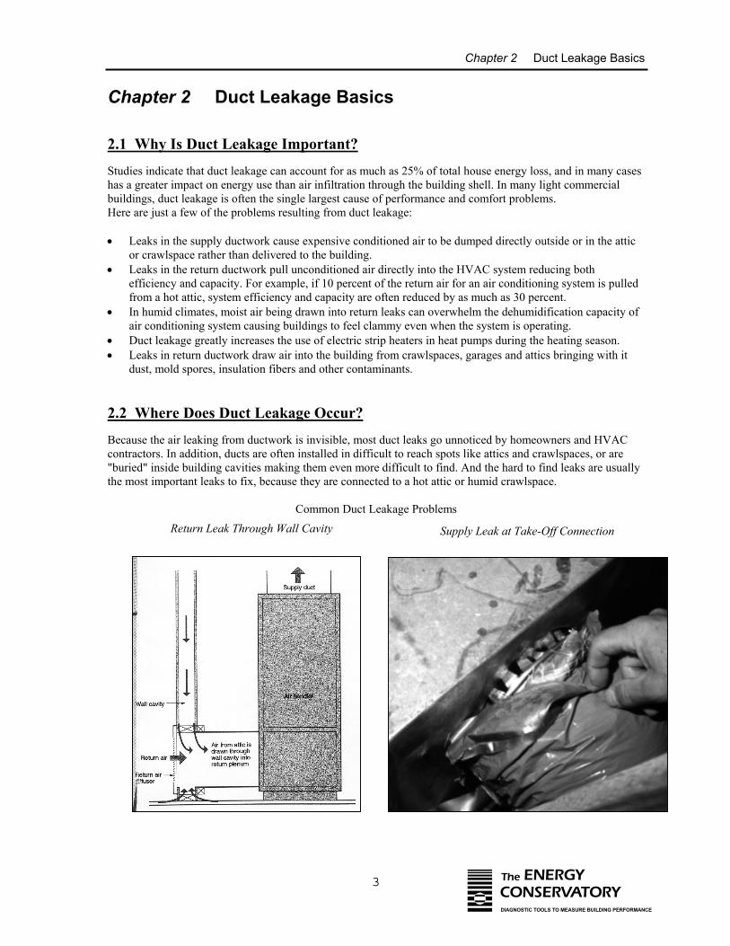
Because the air leaking from ductwork is invisible, most duct leaks go unnoticed by homeowners and HVACcontractors. In addition, ducts are often installed in difficult to reach spots like attics and crawlspaces, or are"buried" inside building cavities making them even more difficult to find. And the hard to find leaks are usuallythe most important leaks to fix, because they are connected to a hot attic or humid crawlspace.
Common Duct Leakage ProblemsReturn Leak Through Wall Cavity Supply Leak at Take-Off Connection
Chapter 2 Duct Leakage Basics
4 The ENERGYCONSERVATORYDIAGNOSTIC TOOLS TO MEASURE BUILDING PERFORMANCE
Duct leaks can be caused by a variety of installation and equipment failures including:
• Poorly fitting joints and seams in the ductwork.• Disconnected or partially disconnected boot connections.• Holes in duct runs.• Use of improperly sealed building cavities for supply or return ducts.• "Platform" return plenums which are connected to unsealed building cavities. • Poor connections between room registers and register boots.• Poorly fitting air handler doors, filter doors and air handler cabinets.• Failed taped joints.
The impact on a particular building will depend on the size of the duct leak, the location of the duct leak andwhether or not the leak is connected to the outside.
2.3 How Much Can Energy Bills Be Reduced By Sealing Duct Leaks?
Numerous studies conducted by nationally recognized research organizations has shown that testing and sealingleaky distribution systems is one of the most cost-effective energy improvements available in many houses. A summary of 19 separate duct leakage studies indicates that the average annual energy savings potential in atypical home is around 17 percent.1
A 1991 study in Florida found:2
• Air conditioner use was decreased by an average of 17.2% in a sample of 46 houses where comprehensiveduct leakage diagnostics and sealing were performed.
• These houses saved an average of $110 per year on cooling bills at a cost of approximately $200 for repairs.
Duct leaks also waste energy in heating climates. A study of 18 houses in Arkansas showed that a duct leakagerepair service saved 21.8% on heating bills by eliminating three-quarters of the duct leakage in the studyhouses.3 In addition to the energy savings, duct leakage repair improves homeowner comfort and reducescallbacks by allowing the HVAC system to work as designed.
2.4 Duct Leakage to the Outside
Duct leakage to the outside has the largest impact on HVAC system performance. Duct leakage to the outsidecommonly results from leaky ductwork running through unconditioned zones (attics, crawlspaces or garages). Most of the duct leakage research studies referenced in this manual have been performed on houses whichcontain significant portions of the duct system in unconditioned zones. However, significant leakage to theoutside can also occur when all ductwork is located within the building envelope. In these cases, leaky ducts
1 Neme, Chris et. al. 1999, "Energy Savings Potential From Addressing Residential Air Conditioner and HeatPump Installation Problems".
2 Cummings, James et. al. 1991, "Investigation of Air Distribution System Leakage and its Impacts in CentralFlorida Homes".
3 Davis, Bruce 1991, "The Impact of Air Distribution System Leakage on Heating Energy Consumption inArkansas Homes".
Chapter 2 Duct Leakage Basics
5 The ENERGYCONSERVATORYDIAGNOSTIC TOOLS TO MEASURE BUILDING PERFORMANCE
passing through wall or floor cavities (or the cavities themselves may be used as supply or return ducts) create apressure differential between the cavity containing the ductwork and other building cavities indirectly connectedto the outside. Air can be forced through these leaks whenever the air handler fan is operating.
2.5 Duct Leakage to the Inside
Much less is known about the energy and system efficiency impacts of duct leakage inside the house. A study ofnew houses in Minnesota has shown that the duct systems are very leaky, but that very little of that leakage wasconnected directly or indirectly to the outside.4 One of the primary causes of duct leakage in Minnesota houseswas found to be very leaky basement return systems which use panned under floor joists as return ductwork.Because most of the duct leakage was occurring within the conditioned space of the house, the energy efficiencypenalty from this leakage is thought to be much less significant. Note: In Minnesota, basements are typicallyconsidered heated space.
However, the Minnesota study did find that leaky return systems can cause the basement (where the furnace andwater heater are typically located) to depressurize to the point where combustion products from the water heateror furnace would spill into the house. Negative pressures from return leaks can also contribute to increasedmoisture and radon entry into houses. In addition, summertime comfort problems were often experienced due tosupply duct leaks in the basement delivering cool air to the basement even though the basements have little orno cooling loads. These problems all suggest that controlling duct leakage to the inside may, in some cases, bejust as important as leakage to the outside.
4 Nelson, Gary et. al. 1993, "Measured Duct Leakage, Mechanical System Induced Pressures and Infiltration in EightRandomly Selected New Minnesota Houses".
Chapter 3 System Components
6 The ENERGYCONSERVATORYDIAGNOSTIC TOOLS TO MEASURE BUILDING PERFORMANCE
Chapter 3 System Components
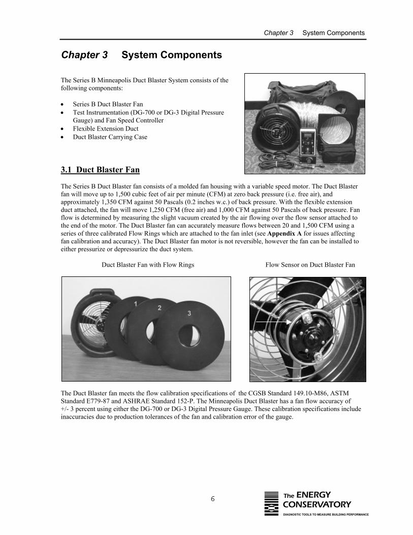
The Series B Minneapolis Duct Blaster System consists of thefollowing components:
• Series B Duct Blaster Fan• Test Instrumentation (DG-700 or DG-3 Digital Pressure
Gauge) and Fan Speed Controller• Flexible Extension Duct • Duct Blaster Carrying Case
3.1 Duct Blaster Fan
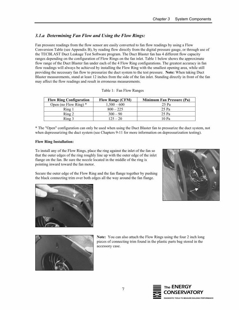
The Series B Duct Blaster fan consists of a molded fan housing with a variable speed motor. The Duct Blasterfan will move up to 1,500 cubic feet of air per minute (CFM) at zero back pressure (i.e. free air), andapproximately 1,350 CFM against 50 Pascals (0.2 inches w.c.) of back pressure. With the flexible extensionduct attached, the fan will move 1,250 CFM (free air) and 1,000 CFM against 50 Pascals of back pressure. Fanflow is determined by measuring the slight vacuum created by the air flowing over the flow sensor attached tothe end of the motor. The Duct Blaster fan can accurately measure flows between 20 and 1,500 CFM using aseries of three calibrated Flow Rings which are attached to the fan inlet (see Appendix A for issues affectingfan calibration and accuracy). The Duct Blaster fan motor is not reversible, however the fan can be installed toeither pressurize or depressurize the duct system.
Duct Blaster Fan with Flow Rings Flow Sensor on Duct Blaster Fan
The Duct Blaster fan meets the flow calibration specifications of the CGSB Standard 149.10-M86, ASTMStandard E779-87 and ASHRAE Standard 152-P. The Minneapolis Duct Blaster has a fan flow accuracy of +/- 3 percent using either the DG-700 or DG-3 Digital Pressure Gauge. These calibration specifications includeinaccuracies due to production tolerances of the fan and calibration error of the gauge.
Chapter 3 System Components
7 The ENERGYCONSERVATORYDIAGNOSTIC TOOLS TO MEASURE BUILDING PERFORMANCE
3.1.a Determining Fan Flow and Using the Flow Rings:
Fan pressure readings from the flow sensor are easily converted to fan flow readings by using a FlowConversion Table (see Appendix B), by reading flow directly from the digital pressure gauge, or through use ofthe TECBLAST Duct Leakage Test Software program. The Duct Blaster fan has 4 different flow capacityranges depending on the configuration of Flow Rings on the fan inlet. Table 1 below shows the approximateflow range of the Duct Blaster fan under each of the 4 Flow Ring configurations. The greatest accuracy in fanflow readings will always be achieved by installing the Flow Ring with the smallest opening area, while stillproviding the necessary fan flow to pressurize the duct system to the test pressure. Note: When taking DuctBlaster measurements, stand at least 12 inches from the side of the fan inlet. Standing directly in front of the fanmay affect the flow readings and result in erroneous measurements.
Table 1: Fan Flow Ranges
Flow Ring Configuration Flow Range (CFM) Minimum Fan Pressure (Pa)Open (no Flow Ring) * 1,500 – 600 25 Pa
Ring 1 800 – 225 25 Pa Ring 2 300 – 90 25 Pa Ring 3 125 – 20 10 Pa
* The "Open" configuration can only be used when using the Duct Blaster fan to pressurize the duct system, notwhen depressurizing the duct system (see Chapters 9-11 for more information on depressurization testing).
Flow Ring Installation:
To install any of the Flow Rings, place the ring against the inlet of the fan sothat the outer edges of the ring roughly line up with the outer edge of the inletflange on the fan. Be sure the nozzle located in the middle of the ring ispointing inward toward the fan motor.
Secure the outer edge of the Flow Ring and the fan flange together by pushingthe black connecting trim over both edges all the way around the fan flange.
Note: You can also attach the Flow Rings using the four 2 inch longpieces of connecting trim found in the plastic parts bag stored in theaccessory case.
Chapter 3 System Components
8 The ENERGYCONSERVATORYDIAGNOSTIC TOOLS TO MEASURE BUILDING PERFORMANCE
In addition to the 3 Flow Rings, the Duct Blaster fan comes with a nylonfan cap to cover the inlet of fan, and a foam foot which can be used tostabilize the fan housing during fan operation.
3.2 Test Instrumentation (Pressure and Fan Flow Gauges)
There are two instrumentation options available with the Minneapolis Duct Blaster; the DG-700 or DG-3Digital Gauges.
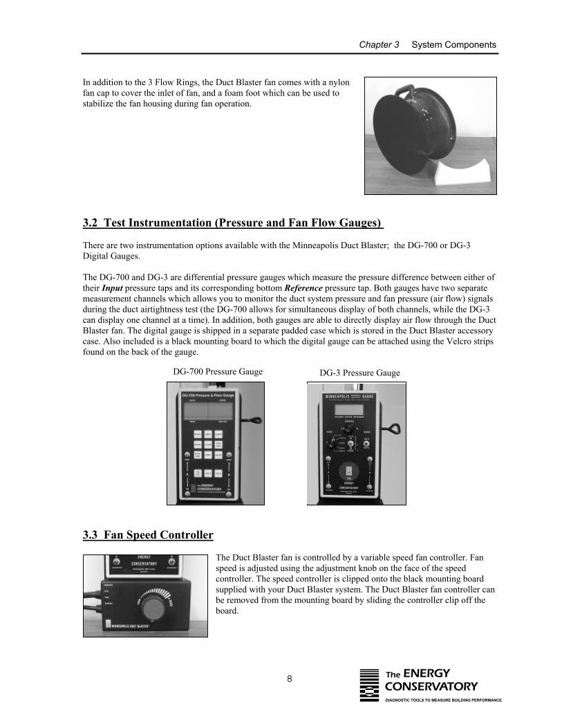
The DG-700 and DG-3 are differential pressure gauges which measure the pressure difference between either oftheir Input pressure taps and its corresponding bottom Reference pressure tap. Both gauges have two separatemeasurement channels which allows you to monitor the duct system pressure and fan pressure (air flow) signalsduring the duct airtightness test (the DG-700 allows for simultaneous display of both channels, while the DG-3can display one channel at a time). In addition, both gauges are able to directly display air flow through the DuctBlaster fan. The digital gauge is shipped in a separate padded case which is stored in the Duct Blaster accessorycase. Also included is a black mounting board to which the digital gauge can be attached using the Velcro stripsfound on the back of the gauge.
DG-3 Pressure GaugeDG-700 Pressure Gauge
3.3 Fan Speed Controller
The Duct Blaster fan is controlled by a variable speed fan controller. Fanspeed is adjusted using the adjustment knob on the face of the speedcontroller. The speed controller is clipped onto the black mounting boardsupplied with your Duct Blaster system. The Duct Blaster fan controller canbe removed from the mounting board by sliding the controller clip off theboard.
Chapter 3 System Components
9 The ENERGYCONSERVATORYDIAGNOSTIC TOOLS TO MEASURE BUILDING PERFORMANCE
3.4 Flexible Extension Duct
The flexible extension duct consists of a 12 foot long section of10" round flexible duct with one square and one round blackplastic transition piece attached at either end. The flexibleextension duct is used to connect the Duct Blaster fan to the ductsystem. The round transition piece connects to either the fanexhaust flange (pressurization testing) or the fan inlet flange(depressurization testing), while the square transition piece canbe attached directly to a large return register, or installed at theair handler cabinet. The extension duct allows the Duct Blasterfan air flow to be easily directed to the duct system while leavingthe fan on the floor or on a table.
•
•
The flexible extension duct is connected to the fan flange usingblack connecting trim. To connect the round transition piece to theDuct Blaster fan, first place the round transition piece against thefan flange so that the outer edges of the transition piece line up withthe outer edge of the fan flange. Secure the outer edge of thetransition piece and the fan flange together by pushing the blackconnecting trim over both edges all the way around the fan (similarto how Flow Rings are attached to the fan).
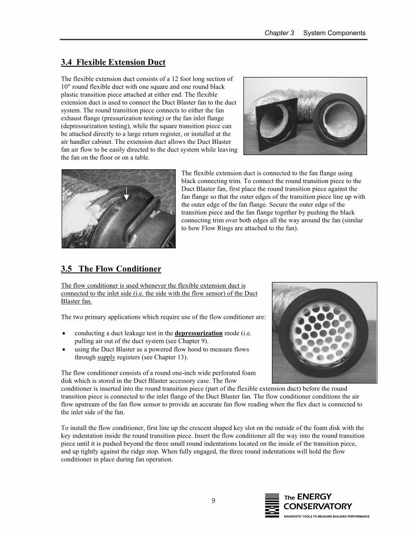
3.5 The Flow Conditioner
The flow conditioner is used whenever the flexible extension duct isconnected to the inlet side (i.e. the side with the flow sensor) of the DuctBlaster fan.
The two primary applications which require use of the flow conditioner are:
conducting a duct leakage test in the depressurization mode (i.e.pulling air out of the duct system (see Chapter 9).using the Duct Blaster as a powered flow hood to measure flowsthrough supply registers (see Chapter 13).
The flow conditioner consists of a round one-inch wide perforated foamdisk which is stored in the Duct Blaster accessory case. The flowconditioner is inserted into the round transition piece (part of the flexible extension duct) before the roundtransition piece is connected to the inlet flange of the Duct Blaster fan. The flow conditioner conditions the airflow upstream of the fan flow sensor to provide an accurate fan flow reading when the flex duct is connected tothe inlet side of the fan.
To install the flow conditioner, first line up the crescent shaped key slot on the outside of the foam disk with thekey indentation inside the round transition piece. Insert the flow conditioner all the way into the round transitionpiece until it is pushed beyond the three small round indentations located on the inside of the transition piece,and up tightly against the ridge stop. When fully engaged, the three round indentations will hold the flowconditioner in place during fan operation.
Chapter 3 System Components
10 The ENERGYCONSERVATORYDIAGNOSTIC TOOLS TO MEASURE BUILDING PERFORMANCE
3.6 Duct Blaster Carrying Case
The Duct Blaster system is stored in the lightweight fabric carrying case. A shoulder strap on the carrying caseprovides an easy method for carrying the system to and from testing locations. Inside the carrying case you willalso find the Operation Manual, laminated flow table, extra tubing and a static pressure probe.
3.7 TECBLAST Duct Airtightness Test Software (Optional)
TECBLAST is a duct airtightness test analysis program for Windows computers. The TECBLAST program canbe used to calculate and display test results from a Duct Blaster airtightness test. In addition, TECBLAST'schoice of professional looking reports makes it simple to present the results of the test to your customers.
3.7.a TECBLAST Features:
• Designed specifically for use with Minneapolis Duct Blaster Systems.• Easy entry of all test data.• Calculation and display of test results including leakage rate in cubic feet per minute (CFM), leakage area
in square inches, leakage as a percent of system air flow, and estimated annual system efficiency loss fromthe measured leakage rate.
• Built-in report generator and file storage features.• TECBLAST lets you print your company logo directly on the reports.• On-line Help.• Compatible with all Windows computers.
Note: If you purchased TECBLAST, you will receive a separate software operation manual. A 30 daydemonstration copy of TECBLAST is available from The Energy Conservatory's website atwww.energyconservatory.com.
Chapter 4 Prepare the Duct System and Building for Testing
11 The ENERGYCONSERVATORYDIAGNOSTIC TOOLS TO MEASURE BUILDING PERFORMANCE
Chapter 4 Prepare the Duct System and Building for Testing
In order to conduct a duct airtightness test, you will need to prepare both the duct system and building. Thistypically includes temporarily sealing off intentional openings in the duct system (e.g. registers), and adjustingHVAC controls. The following setup procedures are recommended by The Energy Conservatory. If you areconducting the airtightness test according to a specific program guideline, the program guidelines may requireyou to set up the duct system and building differently than described below.
• Adjust the HVAC system controls so that the air handler fan does not turn on during the test.
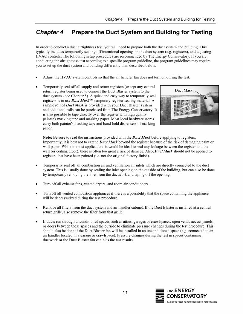
• Temporarily seal off all supply and return registers (except any centralreturn register being used to connect the Duct Blaster system to theduct system - see Chapter 5). A quick and easy way to temporarily sealregisters is to use Duct Mask™ temporary register sealing material. Asample roll of Duct Mask is provided with your Duct Blaster systemand additional rolls can be purchased from The Energy Conservatory. Itis also possible to tape directly over the register with high qualitypainter's masking tape and masking paper. Most local hardware storescarry both painter's masking tape and hand-held dispensers of maskingpaper.
Note: Be sure to read the instructions provided with the Duct Mask before applying to registers.Importantly, it is best not to extend Duct Mask beyond the register because of the risk of damaging paint orwall paper. While in most applications it would be ideal to seal any leakage between the register and thewall (or ceiling, floor), there is often too great a risk of damage. Also, Duct Mask should not be applied toregisters that have been painted (i.e. not the original factory finish).
• Temporarily seal off all combustion air and ventilation air inlets which are directly connected to the ductsystem. This is usually done by sealing the inlet opening on the outside of the building, but can also be doneby temporarily removing the inlet from the ductwork and taping off the opening.
• Turn off all exhaust fans, vented dryers, and room air conditioners.
• Turn off all vented combustion appliances if there is a possibility that the space containing the appliancewill be depressurized during the test procedure.
• Remove all filters from the duct system and air handler cabinet. If the Duct Blaster is installed at a centralreturn grille, also remove the filter from that grille.
• If ducts run through unconditioned spaces such as attics, garages or crawlspaces, open vents, access panels,or doors between those spaces and the outside to eliminate pressure changes during the test procedure. Thisshould also be done if the Duct Blaster fan will be installed in an unconditioned space (e.g. connected to anair handler located in a garage or crawlspace). Pressure changes during the test in spaces containingductwork or the Duct Blaster fan can bias the test results.
Duct Mask
Chapter 5 Setting Up the Duct Blaster for Pressurization Testing
12 The ENERGYCONSERVATORYDIAGNOSTIC TOOLS TO MEASURE BUILDING PERFORMANCE
Chapter 5 Setting Up the Duct Blaster for Pressurization Testing
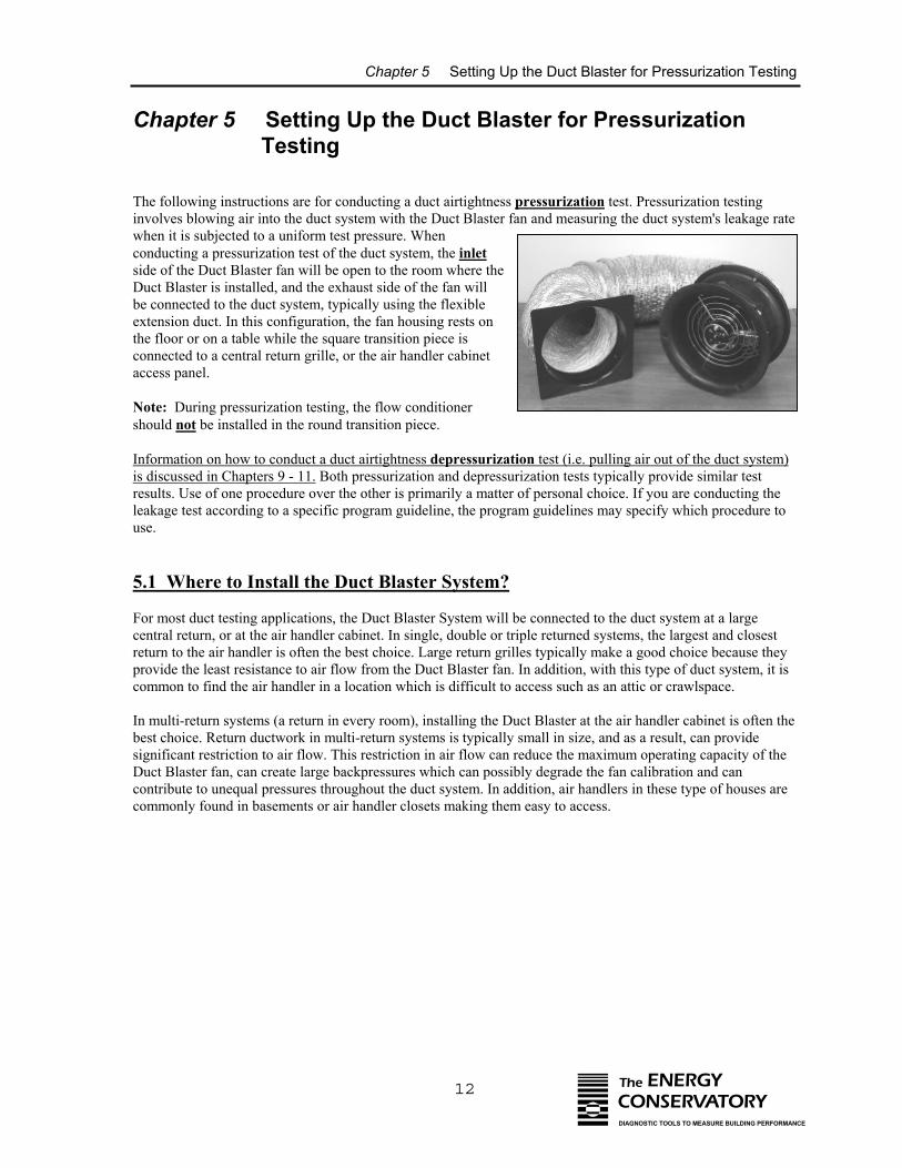
The following instructions are for conducting a duct airtightness pressurization test. Pressurization testinginvolves blowing air into the duct system with the Duct Blaster fan and measuring the duct system's leakage ratewhen it is subjected to a uniform test pressure. Whenconducting a pressurization test of the duct system, the inletside of the Duct Blaster fan will be open to the room where theDuct Blaster is installed, and the exhaust side of the fan willbe connected to the duct system, typically using the flexibleextension duct. In this configuration, the fan housing rests onthe floor or on a table while the square transition piece isconnected to a central return grille, or the air handler cabinetaccess panel.
Note: During pressurization testing, the flow conditionershould not be installed in the round transition piece.
Information on how to conduct a duct airtightness depressurization test (i.e. pulling air out of the duct system)is discussed in Chapters 9 - 11. Both pressurization and depressurization tests typically provide similar testresults. Use of one procedure over the other is primarily a matter of personal choice. If you are conducting theleakage test according to a specific program guideline, the program guidelines may specify which procedure touse.
5.1 Where to Install the Duct Blaster System?
For most duct testing applications, the Duct Blaster System will be connected to the duct system at a largecentral return, or at the air handler cabinet. In single, double or triple returned systems, the largest and closestreturn to the air handler is often the best choice. Large return grilles typically make a good choice because theyprovide the least resistance to air flow from the Duct Blaster fan. In addition, with this type of duct system, it iscommon to find the air handler in a location which is difficult to access such as an attic or crawlspace.
In multi-return systems (a return in every room), installing the Duct Blaster at the air handler cabinet is often thebest choice. Return ductwork in multi-return systems is typically small in size, and as a result, can providesignificant restriction to air flow. This restriction in air flow can reduce the maximum operating capacity of theDuct Blaster fan, can create large backpressures which can possibly degrade the fan calibration and cancontribute to unequal pressures throughout the duct system. In addition, air handlers in these type of houses arecommonly found in basements or air handler closets making them easy to access.
Chapter 5 Setting Up the Duct Blaster for Pressurization Testing
13 The ENERGYCONSERVATORYDIAGNOSTIC TOOLS TO MEASURE BUILDING PERFORMANCE
5.2 Connecting the Duct Blaster to the Duct System
The Duct Blaster System can be connected to the duct system at either a central return, or at the air handlercabinet (i.e. blower compartment access panel).
5.2.a Installing at a Central Return:
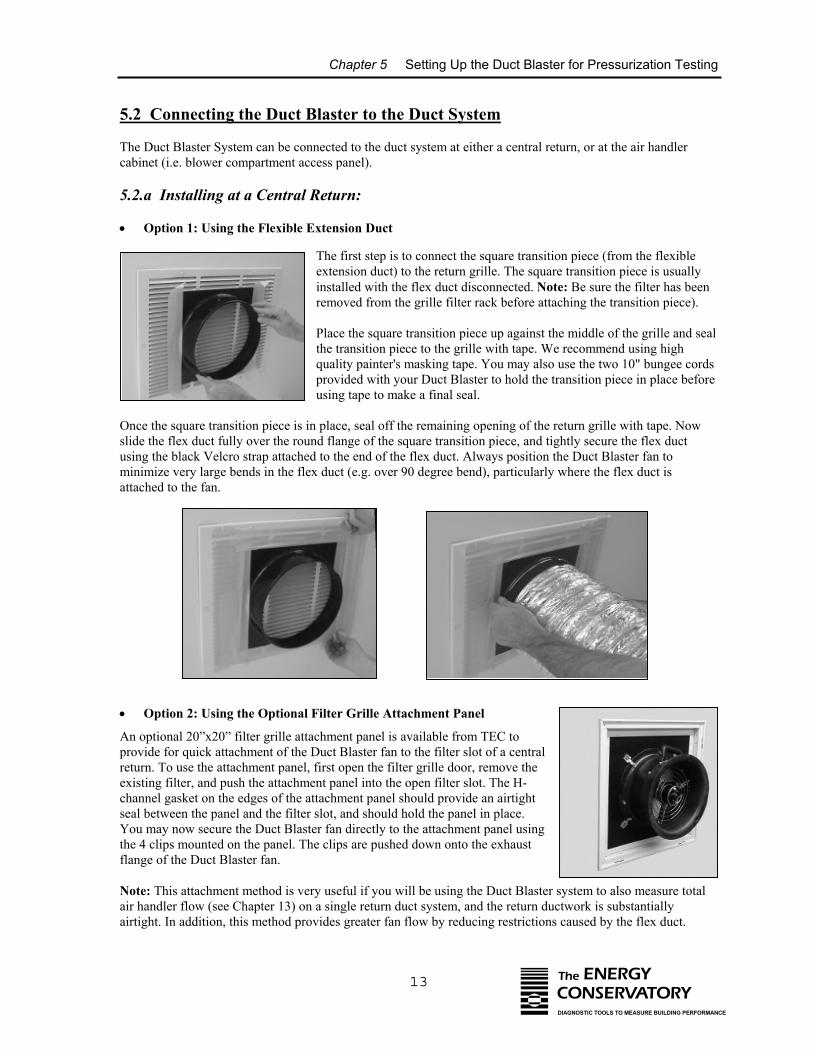
• Option 1: Using the Flexible Extension Duct
The first step is to connect the square transition piece (from the flexibleextension duct) to the return grille. The square transition piece is usuallyinstalled with the flex duct disconnected. Note: Be sure the filter has beenremoved from the grille filter rack before attaching the transition piece).
Place the square transition piece up against the middle of the grille and sealthe transition piece to the grille with tape. We recommend using highquality painter's masking tape. You may also use the two 10" bungee cordsprovided with your Duct Blaster to hold the transition piece in place beforeusing tape to make a final seal.
Once the square transition piece is in place, seal off the remaining opening of the return grille with tape. Nowslide the flex duct fully over the round flange of the square transition piece, and tightly secure the flex ductusing the black Velcro strap attached to the end of the flex duct. Always position the Duct Blaster fan tominimize very large bends in the flex duct (e.g. over 90 degree bend), particularly where the flex duct isattached to the fan.
• Option 2: Using the Optional Filter Grille Attachment Panel
An optional 20”x20” filter grille attachment panel is available from TEC toprovide for quick attachment of the Duct Blaster fan to the filter slot of a centralreturn. To use the attachment panel, first open the filter grille door, remove theexisting filter, and push the attachment panel into the open filter slot. The H-channel gasket on the edges of the attachment panel should provide an airtightseal between the panel and the filter slot, and should hold the panel in place.You may now secure the Duct Blaster fan directly to the attachment panel usingthe 4 clips mounted on the panel. The clips are pushed down onto the exhaustflange of the Duct Blaster fan.
Note: This attachment method is very useful if you will be using the Duct Blaster system to also measure totalair handler flow (see Chapter 13) on a single return duct system, and the return ductwork is substantiallyairtight. In addition, this method provides greater fan flow by reducing restrictions caused by the flex duct.
Chapter 5 Setting Up the Duct Blaster for Pressurization Testing
14 The ENERGYCONSERVATORYDIAGNOSTIC TOOLS TO MEASURE BUILDING PERFORMANCE
5.2.b Installing at the Air Handler Cabinet:
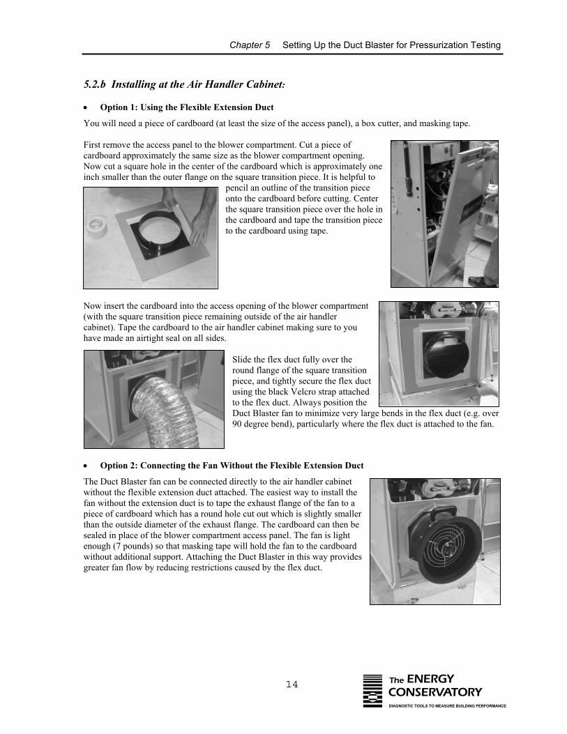
• Option 1: Using the Flexible Extension Duct
You will need a piece of cardboard (at least the size of the access panel), a box cutter, and masking tape.
First remove the access panel to the blower compartment. Cut a piece ofcardboard approximately the same size as the blower compartment opening.Now cut a square hole in the center of the cardboard which is approximately oneinch smaller than the outer flange on the square transition piece. It is helpful to
pencil an outline of the transition pieceonto the cardboard before cutting. Centerthe square transition piece over the hole inthe cardboard and tape the transition pieceto the cardboard using tape.
•
Now insert the cardboard into the access opening of the blower compartment(with the square transition piece remaining outside of the air handlercabinet). Tape the cardboard to the air handler cabinet making sure to youhave made an airtight seal on all sides.
Slide the flex duct fully over theround flange of the square transitionpiece, and tightly secure the flex ductusing the black Velcro strap attachedto the flex duct. Always position theDuct Blaster fan to minimize very large bends in the flex duct (e.g. over90 degree bend), particularly where the flex duct is attached to the fan.
Option 2: Connecting the Fan Without the Flexible Extension Duct
The Duct Blaster fan can be connected directly to the air handler cabinetwithout the flexible extension duct attached. The easiest way to install thefan without the extension duct is to tape the exhaust flange of the fan to apiece of cardboard which has a round hole cut out which is slightly smallerthan the outside diameter of the exhaust flange. The cardboard can then besealed in place of the blower compartment access panel. The fan is lightenough (7 pounds) so that masking tape will hold the fan to the cardboardwithout additional support. Attaching the Duct Blaster in this way providesgreater fan flow by reducing restrictions caused by the flex duct.
Chapter 5 Setting Up the Duct Blaster for Pressurization Testing
15 The ENERGYCONSERVATORYDIAGNOSTIC TOOLS TO MEASURE BUILDING PERFORMANCE
Note: If the air flow exiting from the Duct Blaster is severely obstructed by theair handler fan or other air handler components, this may significantly reduce thetotal flow capacity of the Duct Blaster. If this is a problem, try attaching theDuct Blaster fan to the blower compartment access opening using a smallcardboard box rather than a flat piece of cardboard. This will tend to increase theDuct Blaster fan flow by providing less restriction to air flow as it enters the airhandler blower compartment.
5.3 The Gauge Mounting Board
The black mounting board for the DG-700 or DG-3 digital pressure gauge and fan speed controller can beattached to any door or vertical surface using the C-clamp connected to the back of the board. The mountingboard can also be attached to a horizontal surface by rotating the clamp 90 degrees. The gauge mounting boardcan also be placed on the floor near the Duct Blaster fan.
5.4 Gauge Tubing Connections for Pressurization Testing
The Duct Blaster comes with 2 pieces of color coded tubing - a 15 foot length of green tubing for measuringduct system pressure, and a 10 foot length of red tubing to measure fan pressure and flow. Connect the tubing tothe gauge(s) as shown below:
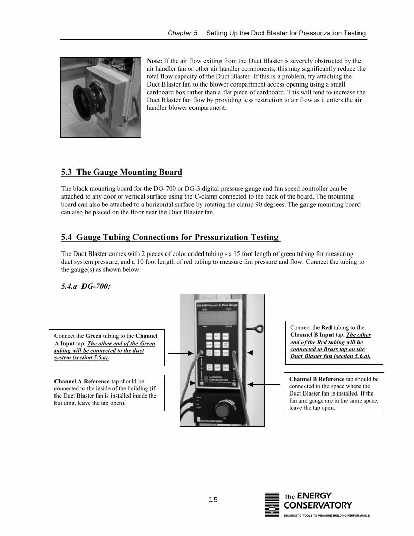
5.4.a DG-700:
Connect the Green tubing to the ChannelA Input tap. The other end of the Greentubing will be connected to the ductsystem (section 5.5.a).
Connect the Red tubing to theChannel B Input tap. The otherend of the Red tubing will beconnected to Brass tap on theDuct Blaster fan (section 5.6.a).
Channel A Reference tap should beconnected to the inside of the building (ifthe Duct Blaster fan is installed inside thebuilding, leave the tap open).
Channel B Reference tap should beconnected to the space where theDuct Blaster fan is installed. If thefan and gauge are in the same space,leave the tap open.
Chapter 5 Setting Up the Duct Blaster for Pressurization Testing
16 The ENERGYCONSERVATORYDIAGNOSTIC TOOLS TO MEASURE BUILDING PERFORMANCE
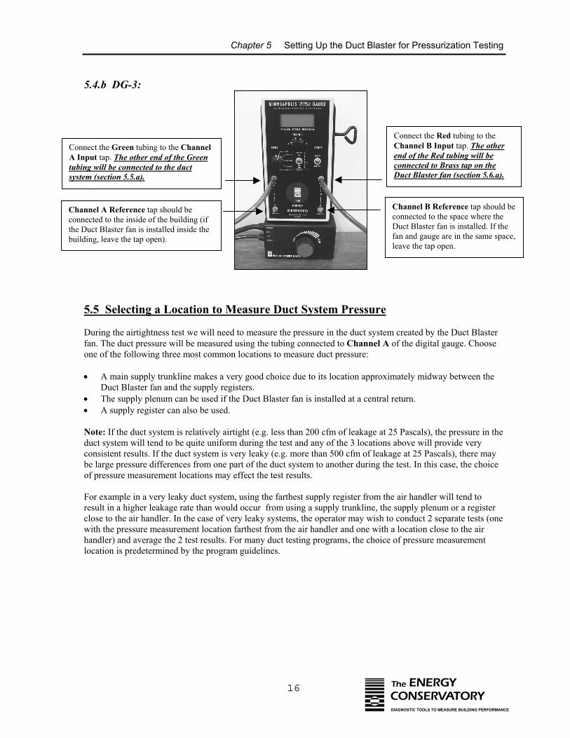
5.4.b DG-3:
•
• •
Connect the Green tubing to the ChannelA Input tap. The other end of the Greentubing will be connected to the ductsystem (section 5.5.a).
Connect the Red tubing to theChannel B Input tap. The otherend of the Red tubing will beconnected to Brass tap on theDuct Blaster fan (section 5.6.a).
Channel A Reference tap should beconnected to the inside of the building (ifthe Duct Blaster fan is installed inside thebuilding, leave the tap open).
Channel B Reference tap should beconnected to the space where theDuct Blaster fan is installed. If thefan and gauge are in the same space,leave the tap open.
5.5 Selecting a Location to Measure Duct System Pressure
During the airtightness test we will need to measure the pressure in the duct system created by the Duct Blasterfan. The duct pressure will be measured using the tubing connected to Channel A of the digital gauge. Chooseone of the following three most common locations to measure duct pressure:
A main supply trunkline makes a very good choice due to its location approximately midway between theDuct Blaster fan and the supply registers. The supply plenum can be used if the Duct Blaster fan is installed at a central return.A supply register can also be used.
Note: If the duct system is relatively airtight (e.g. less than 200 cfm of leakage at 25 Pascals), the pressure in theduct system will tend to be quite uniform during the test and any of the 3 locations above will provide veryconsistent results. If the duct system is very leaky (e.g. more than 500 cfm of leakage at 25 Pascals), there maybe large pressure differences from one part of the duct system to another during the test. In this case, the choiceof pressure measurement locations may effect the test results.
For example in a very leaky duct system, using the farthest supply register from the air handler will tend toresult in a higher leakage rate than would occur from using a supply trunkline, the supply plenum or a registerclose to the air handler. In the case of very leaky systems, the operator may wish to conduct 2 separate tests (onewith the pressure measurement location farthest from the air handler and one with a location close to the airhandler) and average the 2 test results. For many duct testing programs, the choice of pressure measurementlocation is predetermined by the program guidelines.
Chapter 5 Setting Up the Duct Blaster for Pressurization Testing
17 The ENERGYCONSERVATORYDIAGNOSTIC TOOLS TO MEASURE BUILDING PERFORMANCE
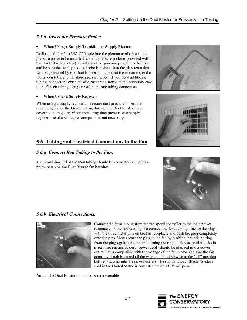
5.5 a Insert the Pressure Probe:
• When Using a Supply Trunkline or Supply Plenum:
Drill a small (1/4" to 3/8" OD) hole into the plenum to allow a staticpressure probe to be installed (a static pressure probe is provided withthe Duct Blaster system). Insert the static pressure probe into the holeand be sure the static pressure probe is pointed into the air stream thatwill be generated by the Duct Blaster fan. Connect the remaining end ofthe Green tubing to the static pressure probe. If you need additionaltubing, connect the extra 30' of clear tubing stored in the accessory caseto the Green tubing using one of the plastic tubing connectors.
• When Using a Supply Register:
When using a supply register to measure duct pressure, insert theremaining end of the Green tubing through the Duct Mask or tapecovering the register. When measuring duct pressure at a supplyregister, use of a static pressure probe is not necessary.
5.6 Tubing and Electrical Connections to the Fan
5.6.a Connect Red Tubing to the Fan:
The remaining end of the Red tubing should be connected to the brasspressure tap on the Duct Blaster fan housing.
5.6.b Electrical Connections:
Connect the female plug from the fan speed controller to the male powerreceptacle on the fan housing. To connect the female plug, line up the plugwith the three metal pins on the fan receptacle and push the plug completelyonto the pins. Now secure the plug to the fan by pushing the locking ringfrom the plug against the fan and turning the ring clockwise until it locks inplace. The remaining cord (power cord) should be plugged into a poweroutlet that is compatible with the voltage of the fan motor (be sure the fancontroller knob is turned all the way counter clockwise to the "off" positionbefore plugging into the power outlet). The standard Duct Blaster Systemsold in the United States is compatible with 110V AC power.
Note: The Duct Blaster fan motor is not reversible
Chapter 6 Conducting a Total Leakage Pressurization Test
18 The ENERGYCONSERVATORYDIAGNOSTIC TOOLS TO MEASURE BUILDING PERFORMANCE
Chapter 6 Conducting a Total Leakage Pressurization Test
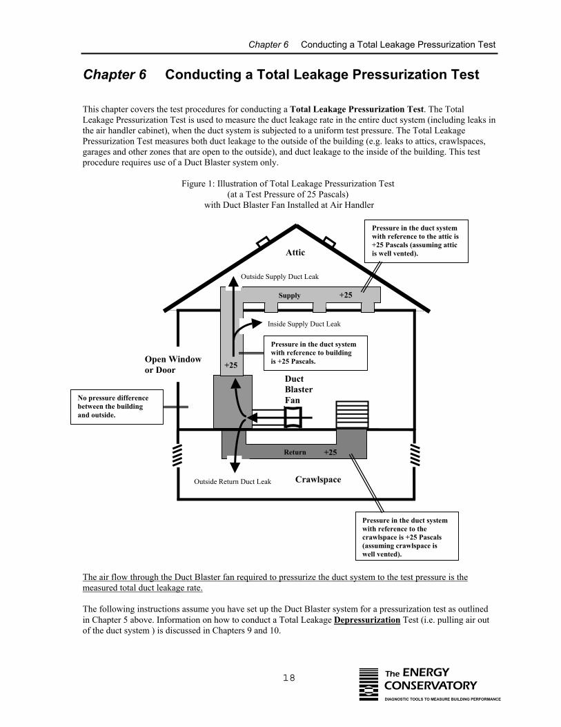
This chapter covers the test procedures for conducting a Total Leakage Pressurization Test. The TotalLeakage Pressurization Test is used to measure the duct leakage rate in the entire duct system (including leaks inthe air handler cabinet), when the duct system is subjected to a uniform test pressure. The Total LeakagePressurization Test measures both duct leakage to the outside of the building (e.g. leaks to attics, crawlspaces,garages and other zones that are open to the outside), and duct leakage to the inside of the building. This testprocedure requires use of a Duct Blaster system only.
Figure 1: Illustration of Total Leakage Pressurization Test (at a Test Pressure of 25 Pascals)
with Duct Blaster Fan Installed at Air Handler
The air flow through the Duct Blaster fan required to pressurize the duct system to the test pressure is themeasured total duct leakage rate.
The following instructions assume you have set up the Duct Blaster system for a pressurization test as outlinedin Chapter 5 above. Information on how to conduct a Total Leakage Depressurization Test (i.e. pulling air outof the duct system ) is discussed in Chapters 9 and 10.
Return +25
DuctBlasterFan
Open Windowor Door
Inside Supply Duct Leak
Outside Supply Duct Leak
Outside Return Duct Leak
Supply +25
Attic
Crawlspace
Pressure in the duct systemwith reference to buildingis +25 Pascals.
No pressure differencebetween the buildingand outside.
+25
Pressure in the duct systemwith reference to the attic is+25 Pascals (assuming atticis well vented).
Pressure in the duct systemwith reference to thecrawlspace is +25 Pascals(assuming crawlspace iswell vented).
Chapter 6 Conducting a Total Leakage Pressurization Test
19 The ENERGYCONSERVATORYDIAGNOSTIC TOOLS TO MEASURE BUILDING PERFORMANCE
Note: It is possible to separately measure total supply and return duct leaks by installing a temporary barrier ineither the supply or return opening to the air handler cabinet. With a temporary barrier in place, each side of theduct system can be tested independently. It is also possible to separately measure supply and return leakagebefore the air handler or furnace unit has been installed.
6.1 Final Preparations (Open a Door or Window to the Outside)
Open a door or window between the building and outside to prevent changes in building pressure when the DuctBlaster fan is running. We want to prevent changes in building pressures because the pressure difference acrossduct leaks will be different for leaks to the inside of the building compared with leaks to the outside. Changes inbuilding pressure could be caused by:
⇒ If the Duct Blaster is installed inside the building and there are large leaks between the duct systemand outside, pressurizing the duct system with building air may depressurize the building relativeto outside.
⇒ If the Duct Blaster is installed in an unconditioned space (attic, garage or crawlspace air handler ),pressuring the duct system with outside air may pressurize the building relative to outside.
6.2 Choosing the Test Pressure and Number of Test Readings
6.2.a Test Pressure:
For residential duct systems, we generally recommend that 25 Pascals (0.10 inches w.c.) be used as the testpressure. This pressure has been adopted by the majority of residential duct testing programs in the U.S. because25 Pascals represents a typical operating pressure seen in many residential systems. In cases where 25 Pascals isnot a representative pressure in the duct system being tested, it may be appropriate to use a different testpressure. For example, in small commercial HVAC systems which typically operate at higher duct pressuresthan residential systems, it may be appropriate to use a test pressure greater than 25 Pascals. In extremely leakyduct systems, such as duct systems found in many basement style houses, typical operating pressures in the ductsystem may be significantly less than 25 Pascals. In this case it may be appropriate to use a test pressure lowerthan 25 Pascals.
6.2.b Number of Test Readings:
The most common test procedure is to conduct a One-Point Test to measure duct airtightness. The One-PointTest utilizes a single measurement of Duct Blaster fan flow needed to produce the test pressure in the ductsystem. The One-Point Test provides a quick and simple way to measure duct leakage without the need to havea computer to analyze the test data (although a computer program like TECBLAST can still be useful togenerate reports and store data).
The Multi-Point Test procedure involves testing the duct system over a range of test pressures and analyzing thedata using a duct airtightness test computer program (e.g. TECBLAST). A typical Multi-Point Test of aresidential duct system includes taking measurements at 5 different test pressures including 35 Pascals, 30, 25,20 and 15 Pascals. Making multiple measurements allows some of the errors introduced by fluctuating pressuresand operator error to be averaged out over several measurements, typically increasing test accuracy.
Chapter 6 Conducting a Total Leakage Pressurization Test
20 The ENERGYCONSERVATORYDIAGNOSTIC TOOLS TO MEASURE BUILDING PERFORMANCE
6.3 Total Leakage Test Procedures Using the DG-700
The following test procedures cover use of the DG-700 for both One-Point Tests and Multi-Point Tests. Theseprocedures assume that a test pressure of 25 Pascals is being used.
a) Turn on the DG-700 and place it in the proper Mode:
• DG-700: One-Point Test
Turn on the DG-700 by pressing the ON/OFF button. Press the MODE button three times to put the gauge intothe PR/ FL @25 mode. In this specialized test mode, Channel A is used to measure duct system pressure whileChannel B is used to display estimated duct leakage at a test pressure of 25 Pascals. The leakage estimateshown on Channel B is determined by mathematically adjusting the actual air flow from the Duct Blaster fan toa test pressure of 25 Pascals, using the real-time Channel A duct system pressure reading and a Can’t ReachPressure (CRP) factor. CRP factors are discussed later in this Chapter.
• DG-700: Multi-Point Test
Turn on the gauge by pressing the ON/OFF button. Press the MODE button once to put the gauge into the PR/ FL mode. The PR/ FL mode is a multi-purpose mode used to measure a test pressure on Channel A whilesimultaneously measuring air flow from the Duct Blaster fan on Channel B.
b) Optional measurement of baseline duct pressure (same for both One-Point and Multi-Point Tests).
When conducting a total leakage test, we want to measure the change in duct system pressure caused by airflowing through the Duct Blaster fan. In order to measure this change accurately, we sometimes need to accountfor any existing pressures on the duct system caused by stack, wind and other driving forces. This existing ductsystem pressure is called the "baseline duct pressure".
In many cases, the baseline duct pressure will be very small or zero, and this section of the test procedure can beomitted. For example, during mild weather conditions (e.g. little wind and less than 20 degrees temperaturedifference between inside and outside the building), the baseline duct pressure will typically be less than 1Pascal and omitting baseline pressure measurements will have little or no effect on the final test results.
If it is very windy or there are very large temperature differences between inside and outside, and the ducts arelocated in unconditioned zones (e.g. attics, crawlspaces or garages), baseline duct pressures may be greater than1 Pascal and should be measured. The DG-700 has a built-in baseline measurement procedure which allows theuser to quickly measure and record the baseline pressure on Channel A, and then display the baseline adjustedpressure. This feature makes it possible to “zero out” the baseline duct pressure on Channel A, and display theactual change in duct pressure caused by the Duct Blaster fan.
With the fan sealed off, begin a baseline duct pressure reading from Channel A by pressing the BASELINEbutton. The word “BASELINE” will begin to flash in the Channel A display indicating that the baseline featurehas been initiated. Press START to start the baseline measurement. During a baseline measurement, Channel Awill display a long-term average baseline pressure reading while Channel B is used as a timer in seconds toshow the elapsed measurement time. When you are satisfied with the baseline measurement, press the ENTERbutton to accept and enter the baseline reading into the gauge. The Channel A display will now show an ADJicon to indicate that it is displaying a baseline adjusted duct pressure value.
Chapter 6 Conducting a Total Leakage Pressurization Test
21
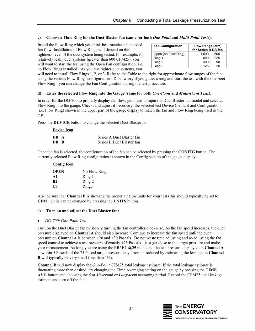
c) Choose a Flow Ring for the Duct Blaster fan (same for both One-Point and Multi-Point Tests).
Install the Flow Ring which you think best matches the neededfan flow. Installation of Flow Rings will depend on thetightness level of the duct system being tested. For example, forrelatively leaky duct systems (greater than 600 CFM25), youwill want to start the test using the Open Fan configuration (i.e.no Flow Rings installed). As you test tighter duct systems, youwill need to install Flow Rings 1, 2, or 3. Refer to the Table to the rigusing the various Flow Rings configurations. Don't worry if you guesFlow Ring - you can change the Fan Configuration during the test pr
d) Enter the selected Flow Ring into the Gauge (same for both
In order for the DG-700 to properly display fan flow, you need to inpFlow Ring into the gauge. Check, and adjust if necessary, the selecte(i.e. Flow Ring) shown in the upper part of the gauge display to matctest.
Press the DEVICE button to change the selected Duct Blaster fan.
Device Icon
DB A Series A Duct Blaster fanDB B Series B Duct Blaster fan
Once the fan is selected, the configuration of the fan can be selected currently selected Flow Ring configuration is shown in the Config se
Config Icon
OPEN No Flow RingA1 Ring 1B2 Ring 2C3 Ring3
Also be sure that Channel B is showing the proper air flow units forCFM). Units can be changed by pressing the UNITS button.
e) Turn on and adjust the Duct Blaster fan:
• DG-700: One-Point Test
Turn on the Duct Blaster fan by slowly turning the fan controller clopressure displayed on Channel A should also increase. Continue to ipressure on Channel A is between +20 and +30 Pascals. Do not waspeed control to achieve a test pressure of exactly +25 Pascals – just your measurement. As long you are using the PR/ FL @25 mode anis within 5 Pascals of the 25 Pascal target pressure, any errors introduB will typically be very small (less than 1%).
Channel B will now display the One-Point CFM25 total leakage estfluctuating more than desired, try changing the Time Averaging settiAVG button and choosing the 5 or 10 second or Long-term averaginestimate and turn off the fan.
Fan Configuration Flow Range (cfm)for Series B DB fan
Open (no Flow Ring) 1,500 - 600Ring 1 800 - 225Ring 2 300 - 90Ring 3 125 - 20
The ENERGYCONSERVATORYDIAGNOSTIC TOOLS TO MEASURE BUILDING PERFORMANCE
ht for approximate flow ranges of the fans wrong and start the test with the incorrect
ocedure.
One-Point and Multi-Point Tests).
ut the Duct Blaster fan model and selectedd test Device (i.e. fan) and Configurationh the fan and Flow Ring being used in the
by pressing the CONFIG button. Thection of the gauge display.
your test (this should typically be set to
ckwise. As the fan speed increases, the ductncrease the fan speed until the ductste time adjusting and re-adjusting the fanget close to the target pressure and maked the test pressure displayed on Channel Aced by estimating the leakage on Channel
imate. If the total leakage estimate isng on the gauge by pressing the TIMEg period. Record the CFM25 total leakage
Chapter 6 Conducting a Total Leakage Pressurization Test
22 The ENERGYCONSERVATORYDIAGNOSTIC TOOLS TO MEASURE BUILDING PERFORMANCE
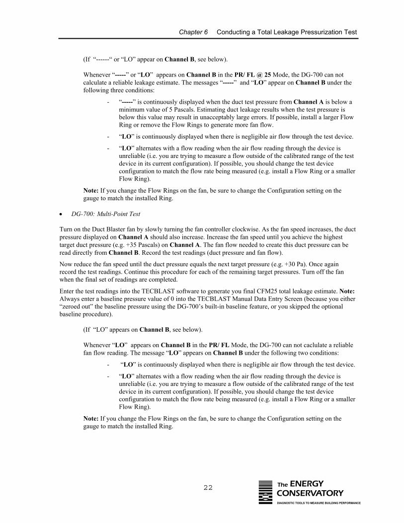
(If “------“ or “LO” appear on Channel B, see below).
Whenever “-----” or “LO” appears on Channel B in the PR/ FL @ 25 Mode, the DG-700 can notcalculate a reliable leakage estimate. The messages “-----” and “LO” appear on Channel B under thefollowing three conditions:
- “-----” is continuously displayed when the duct test pressure from Channel A is below aminimum value of 5 Pascals. Estimating duct leakage results when the test pressure isbelow this value may result in unacceptably large errors. If possible, install a larger FlowRing or remove the Flow Rings to generate more fan flow.
- “LO” is continuously displayed when there is negligible air flow through the test device.
- “LO” alternates with a flow reading when the air flow reading through the device isunreliable (i.e. you are trying to measure a flow outside of the calibrated range of the testdevice in its current configuration). If possible, you should change the test deviceconfiguration to match the flow rate being measured (e.g. install a Flow Ring or a smallerFlow Ring).
Note: If you change the Flow Rings on the fan, be sure to change the Configuration setting on thegauge to match the installed Ring.
• DG-700: Multi-Point Test
Turn on the Duct Blaster fan by slowly turning the fan controller clockwise. As the fan speed increases, the ductpressure displayed on Channel A should also increase. Increase the fan speed until you achieve the highesttarget duct pressure (e.g. +35 Pascals) on Channel A. The fan flow needed to create this duct pressure can beread directly from Channel B. Record the test readings (duct pressure and fan flow).
Now reduce the fan speed until the duct pressure equals the next target pressure (e.g. +30 Pa). Once againrecord the test readings. Continue this procedure for each of the remaining target pressures. Turn off the fanwhen the final set of readings are completed.
Enter the test readings into the TECBLAST software to generate you final CFM25 total leakage estimate. Note:Always enter a baseline pressure value of 0 into the TECBLAST Manual Data Entry Screen (because you either“zeroed out” the baseline pressure using the DG-700’s built-in baseline feature, or you skipped the optionalbaseline procedure).
(If “LO” appears on Channel B, see below).
Whenever “LO” appears on Channel B in the PR/ FL Mode, the DG-700 can not caclulate a reliablefan flow reading. The message “LO” appears on Channel B under the following two conditions:
- “LO” is continuously displayed when there is negligible air flow through the test device.
- “LO” alternates with a flow reading when the air flow reading through the device isunreliable (i.e. you are trying to measure a flow outside of the calibrated range of the testdevice in its current configuration). If possible, you should change the test deviceconfiguration to match the flow rate being measured (e.g. install a Flow Ring or a smallerFlow Ring).
Note: If you change the Flow Rings on the fan, be sure to change the Configuration setting on thegauge to match the installed Ring.
Chapter 6 Conducting a Total Leakage Pressurization Test
23
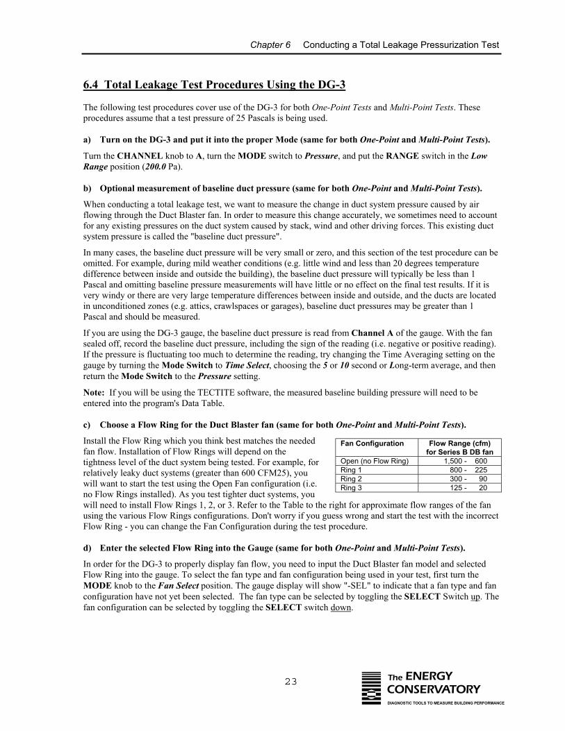
6.4 Total Leakage Test Procedures Using the DG-3
The following test procedures cover use of the DG-3 for both One-Point Tests and Multi-Point Tests. Theseprocedures assume that a test pressure of 25 Pascals is being used.
a) Turn on the DG-3 and put it into the proper Mode (same for both One-Point and Multi-Point Tests).
Turn the CHANNEL knob to A, turn the MODE switch to Pressure, and put the RANGE switch in the LowRange position (200.0 Pa).
b) Optional measurement of baseline duct pressure (same for both One-Point and Multi-Point Tests).
When conducting a total leakage test, we want to measure the change in duct system pressure caused by airflowing through the Duct Blaster fan. In order to measure this change accurately, we sometimes need to accountfor any existing pressures on the duct system caused by stack, wind and other driving forces. This existing ductsystem pressure is called the "baseline duct pressure".
In many cases, the baseline duct pressure will be very small or zero, and this section of the test procedure can beomitted. For example, during mild weather conditions (e.g. little wind and less than 20 degrees temperaturedifference between inside and outside the building), the baseline duct pressure will typically be less than 1Pascal and omitting baseline pressure measurements will have little or no effect on the final test results. If it isvery windy or there are very large temperature differences between inside and outside, and the ducts are locatedin unconditioned zones (e.g. attics, crawlspaces or garages), baseline duct pressures may be greater than 1Pascal and should be measured.
If you are using the DG-3 gauge, the baseline duct pressure is read from Channel A of the gauge. With the fansealed off, record the baseline duct pressure, including the sign of the reading (i.e. negative or positive reading).If the pressure is fluctuating too much to determine the reading, try changing the Time Averaging setting on thegauge by turning the Mode Switch to Time Select, choosing the 5 or 10 second or Long-term average, and thenreturn the Mode Switch to the Pressure setting.
Note: If you will be using the TECTITE software, the measured baseline building pressure will need to beentered into the program's Data Table.
c) Choose a Flow Ring for the Duct Blaster fan (same for both One-Point and Multi-Point Tests).
Install the Flow Ring which you think best matches the neededfan flow. Installation of Flow Rings will depend on thetightness level of the duct system being tested. For example, forrelatively leaky duct systems (greater than 600 CFM25), youwill want to start the test using the Open Fan configuration (i.e.no Flow Rings installed). As you test tighter duct systems, youwill need to install Flow Rings 1, 2, or 3. Refer to the Table to the rigusing the various Flow Rings configurations. Don't worry if you guesFlow Ring - you can change the Fan Configuration during the test pr
d) Enter the selected Flow Ring into the Gauge (same for both O
In order for the DG-3 to properly display fan flow, you need to inputFlow Ring into the gauge. To select the fan type and fan configuratioMODE knob to the Fan Select position. The gauge display will showconfiguration have not yet been selected. The fan type can be selectefan configuration can be selected by toggling the SELECT switch do
Fan Configuration Flow Range (cfm)for Series B DB fan
Open (no Flow Ring) 1,500 - 600Ring 1 800 - 225Ring 2 300 - 90Ring 3 125 - 20
The ENERGYCONSERVATORYDIAGNOSTIC TOOLS TO MEASURE BUILDING PERFORMANCE
ht for approximate flow ranges of the fans wrong and start the test with the incorrect
ocedure.
ne-Point and Multi-Point Tests).
the Duct Blaster fan model and selectedn being used in your test, first turn the "-SEL" to indicate that a fan type and fand by toggling the SELECT Switch up. Thewn.
Chapter 6 Conducting a Total Leakage Pressurization Test
24 The ENERGYCONSERVATORYDIAGNOSTIC TOOLS TO MEASURE BUILDING PERFORMANCE
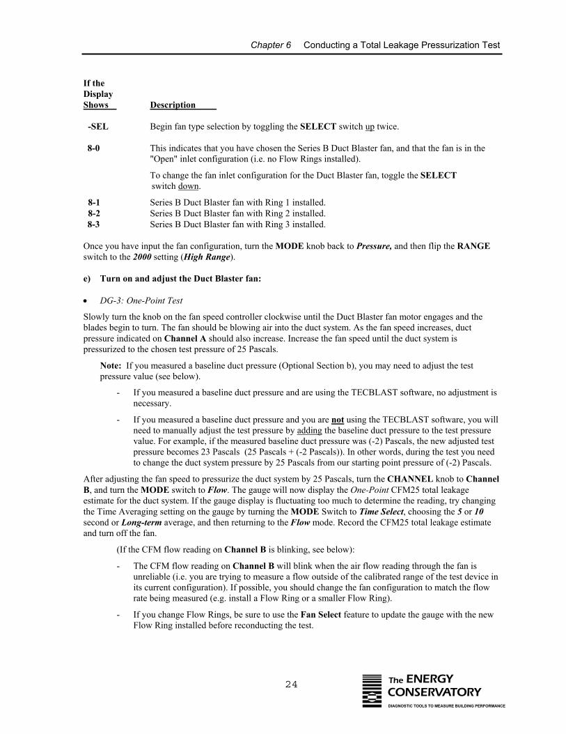
If the DisplayShows Description
-SEL Begin fan type selection by toggling the SELECT switch up twice.
8-0 This indicates that you have chosen the Series B Duct Blaster fan, and that the fan is in the"Open" inlet configuration (i.e. no Flow Rings installed).
To change the fan inlet configuration for the Duct Blaster fan, toggle the SELECT switch down.
8-1 Series B Duct Blaster fan with Ring 1 installed. 8-2 Series B Duct Blaster fan with Ring 2 installed.8-3 Series B Duct Blaster fan with Ring 3 installed.
Once you have input the fan configuration, turn the MODE knob back to Pressure, and then flip the RANGEswitch to the 2000 setting (High Range).
e) Turn on and adjust the Duct Blaster fan:
• DG-3: One-Point Test
Slowly turn the knob on the fan speed controller clockwise until the Duct Blaster fan motor engages and theblades begin to turn. The fan should be blowing air into the duct system. As the fan speed increases, ductpressure indicated on Channel A should also increase. Increase the fan speed until the duct system ispressurized to the chosen test pressure of 25 Pascals.
Note: If you measured a baseline duct pressure (Optional Section b), you may need to adjust the testpressure value (see below).
- If you measured a baseline duct pressure and are using the TECBLAST software, no adjustment isnecessary.
- If you measured a baseline duct pressure and you are not using the TECBLAST software, you willneed to manually adjust the test pressure by adding the baseline duct pressure to the test pressurevalue. For example, if the measured baseline duct pressure was (-2) Pascals, the new adjusted testpressure becomes 23 Pascals (25 Pascals + (-2 Pascals)). In other words, during the test you needto change the duct system pressure by 25 Pascals from our starting point pressure of (-2) Pascals.
After adjusting the fan speed to pressurize the duct system by 25 Pascals, turn the CHANNEL knob to ChannelB, and turn the MODE switch to Flow. The gauge will now display the One-Point CFM25 total leakageestimate for the duct system. If the gauge display is fluctuating too much to determine the reading, try changingthe Time Averaging setting on the gauge by turning the MODE Switch to Time Select, choosing the 5 or 10second or Long-term average, and then returning to the Flow mode. Record the CFM25 total leakage estimateand turn off the fan.
(If the CFM flow reading on Channel B is blinking, see below):
- The CFM flow reading on Channel B will blink when the air flow reading through the fan isunreliable (i.e. you are trying to measure a flow outside of the calibrated range of the test device inits current configuration). If possible, you should change the fan configuration to match the flowrate being measured (e.g. install a Flow Ring or a smaller Flow Ring).
- If you change Flow Rings, be sure to use the Fan Select feature to update the gauge with the newFlow Ring installed before reconducting the test.
Chapter 6 Conducting a Total Leakage Pressurization Test
25 The ENERGYCONSERVATORYDIAGNOSTIC TOOLS TO MEASURE BUILDING PERFORMANCE
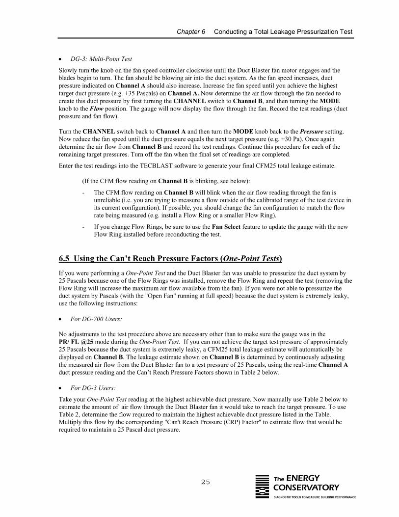
• DG-3: Multi-Point Test
Slowly turn the knob on the fan speed controller clockwise until the Duct Blaster fan motor engages and theblades begin to turn. The fan should be blowing air into the duct system. As the fan speed increases, ductpressure indicated on Channel A should also increase. Increase the fan speed until you achieve the highesttarget duct pressure (e.g. +35 Pascals) on Channel A. Now determine the air flow through the fan needed tocreate this duct pressure by first turning the CHANNEL switch to Channel B, and then turning the MODEknob to the Flow position. The gauge will now display the flow through the fan. Record the test readings (ductpressure and fan flow).
Turn the CHANNEL switch back to Channel A and then turn the MODE knob back to the Pressure setting.Now reduce the fan speed until the duct pressure equals the next target pressure (e.g. +30 Pa). Once againdetermine the air flow from Channel B and record the test readings. Continue this procedure for each of theremaining target pressures. Turn off the fan when the final set of readings are completed.
Enter the test readings into the TECBLAST software to generate your final CFM25 total leakage estimate.
(If the CFM flow reading on Channel B is blinking, see below):
- The CFM flow reading on Channel B will blink when the air flow reading through the fan isunreliable (i.e. you are trying to measure a flow outside of the calibrated range of the test device inits current configuration). If possible, you should change the fan configuration to match the flowrate being measured (e.g. install a Flow Ring or a smaller Flow Ring).
- If you change Flow Rings, be sure to use the Fan Select feature to update the gauge with the newFlow Ring installed before reconducting the test.
6.5 Using the Can’t Reach Pressure Factors (One-Point Tests)
If you were performing a One-Point Test and the Duct Blaster fan was unable to pressurize the duct system by25 Pascals because one of the Flow Rings was installed, remove the Flow Ring and repeat the test (removing theFlow Ring will increase the maximum air flow available from the fan). If you were not able to pressurize theduct system by Pascals (with the "Open Fan" running at full speed) because the duct system is extremely leaky,use the following instructions:
• For DG-700 Users: No adjustments to the test procedure above are necessary other than to make sure the gauge was in the PR/ FL @25 mode during the One-Point Test. If you can not achieve the target test pressure of approximately25 Pascals because the duct system is extremely leaky, a CFM25 total leakage estimate will automatically bedisplayed on Channel B. The leakage estimate shown on Channel B is determined by continuously adjustingthe measured air flow from the Duct Blaster fan to a test pressure of 25 Pascals, using the real-time Channel Aduct pressure reading and the Can’t Reach Pressure Factors shown in Table 2 below.
• For DG-3 Users:
Take your One-Point Test reading at the highest achievable duct pressure. Now manually use Table 2 below toestimate the amount of air flow through the Duct Blaster fan it would take to reach the target pressure. To useTable 2, determine the flow required to maintain the highest achievable duct pressure listed in the Table.Multiply this flow by the corresponding "Can't Reach Pressure (CRP) Factor" to estimate flow that would berequired to maintain a 25 Pascal duct pressure.
Chapter 6 Conducting a Total Leakage Pressurization Test
Table 2: Can't Reach Pressure Factors (25 Pa Target)
- -
P
Example: With no Flow Ring inssystem test pressure of 14 Pascalsfor a duct pressure of 14 Pascals is 1,200 x 1.42 = 1,704 cfm.
Note: The TECBLAST program
6.5.a Potential Errors In One-
Table 3 below show the potential errofactors. There are two main sources of
The actual test pressure (The actual exponent of t
Can’t Reach PressFactor
Table 3: Error in
TestPressure in Pa(Channel A)
5 11015202530 -35 -40 -
Duct Ductressure CRP Pressure CRP(Pa) Factor (Pa) Factor24 1.02 14 1.4223 1.05 13 1.4822 1.08 12 1.5521 1.11 11 1.6420 1.14 10 1.7319 1.18 9 1.8518 1.22 8 1.9817 1.26 7 2.1516 1.31 6 2.3515 1.36 5 2.63
26 The ENERGYCONSERVATORYDIAGNOSTIC TOOLS TO MEASURE BUILDING PERFORMANCE
25
Current Test Pressure (Pa) (Channel A)
talled and the fan running full speed, you are able to achieve a duct with a measured fan flow of 1,200 cfm. The corresponding CRP Factoris 1.42. The estimated total duct leakage at a test pressure of 25 Pascals
automatically applies the CRP Factors to One-Point Test data.
Point CFM25 Estimate from Using the CRP Factors:
rs in the One-Point CFM25 total leakage estimates from using the CRP error:
Channel A) not being equal to the target pressure of 25 Pascals. he leaks being measured differing from the assumed exponent of 0.60.
0.60
ure =
Actual exponent “n”
One-Point Leakage Estimate from CRP Factor
0.54.9%
0.557.7%
0.60.0%
0.65-8.4%
0.7-17.5%
0.75-27.3%
8.8% 4.5% 0.0% -4.7% -9.6% -14.7%5.0% 2.5% 0.0% -2.6% -5.2% -8.0%2.2% 1.1% 0.0% -1.1% -2.3% -3.4%0.0% 0.0% 0.0% 0.0% 0.0% 0.0%1.8% -0.9% 0.0% 0.9% 1.8% 2.7%3.4% -1.7% 0.0% 1.7% 3.3% 4.9%4.8% -2.4% 0.0% 2.3% 4.6% 6.8%
Chapter 6 Conducting a Total Leakage Pressurization Test
27 The ENERGYCONSERVATORYDIAGNOSTIC TOOLS TO MEASURE BUILDING PERFORMANCE
For example, Table 3 shows that for a One-Point 25 Pa duct airtightness test, a 4.5% error would be introducedif the leakage estimate was determined at an actual test pressure of 10 Pa (Channel A), and the actual exponentof the leaks was 0.55 rather than the assumed value of 0.60.
6.6 Unable to Reach a Target Building Pressure During a Multi-Point Test?
If the Duct Blaster fan was unable to achieve the highest target duct pressure (e.g. 35 Pascals) because one ofthe Flow Rings was installed, remove the Flow Ring and repeat the test. If you were not able to reach thehighest target pressure with the "Open Fan" running at full speed because the duct system is extremely leaky,take your first set of test readings the highest achievable duct pressure. Continue your test by using theremaining target pressures which are less than the highest achievable pressure. Enter these test values into theTECBLAST program to generate your total leakage estimate.
6.7 Before Leaving the Building
Be sure you have returned the building to its original condition before leaving. This includes removing anytemporary register seals, turning HVAC controls to their original settings and closing access doors or ventsopened during the test. In addition, it is highly recommended that the test procedures outlined in Chapters 14and 15 be performed before leaving the building.
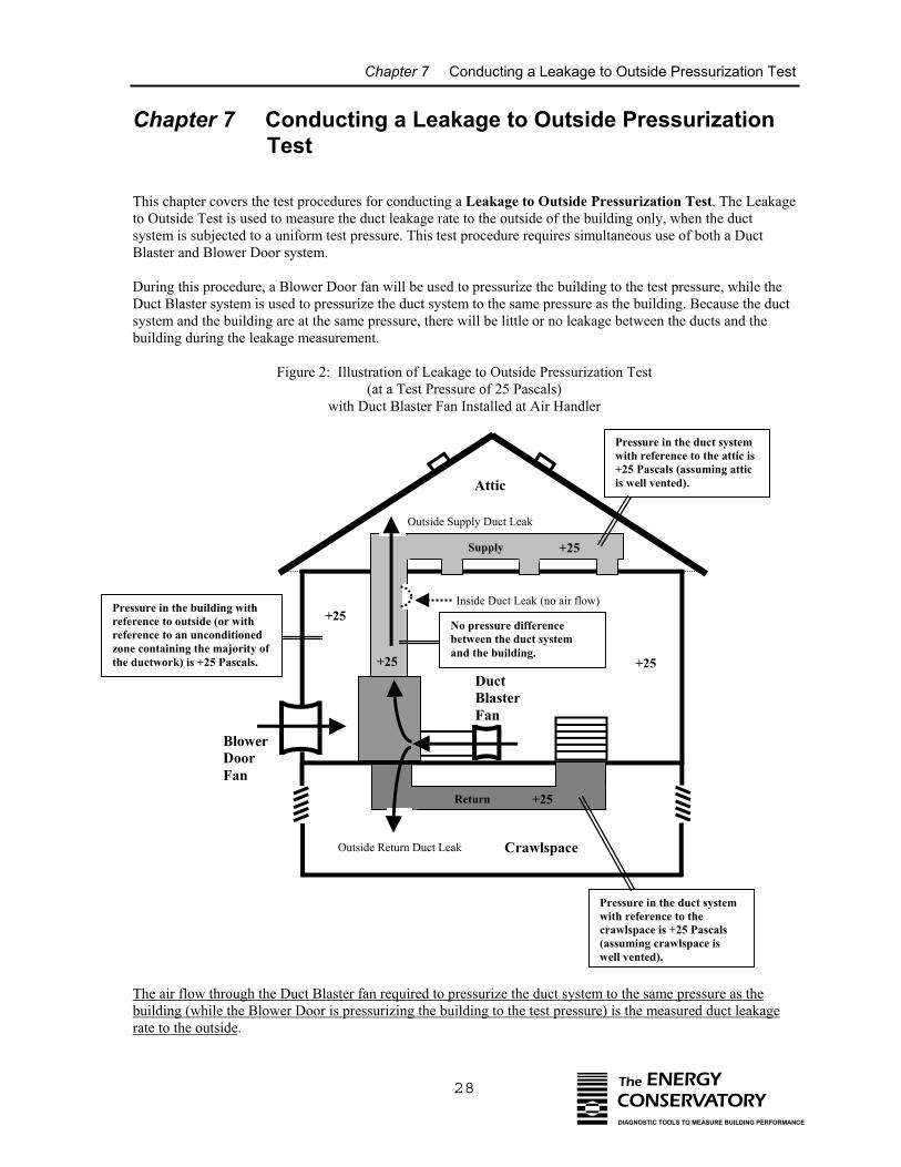
Chapter 7 Conducting a Leakage to Outside Pressurization Test
28 The ENERGYCONSERVATORYDIAGNOSTIC TOOLS TO MEASURE BUILDING PERFORMANCE
Chapter 7 Conducting a Leakage to Outside Pressurization Test
This chapter covers the test procedures for conducting a Leakage to Outside Pressurization Test. The Leakageto Outside Test is used to measure the duct leakage rate to the outside of the building only, when the ductsystem is subjected to a uniform test pressure. This test procedure requires simultaneous use of both a DuctBlaster and Blower Door system.
During this procedure, a Blower Door fan will be used to pressurize the building to the test pressure, while theDuct Blaster system is used to pressurize the duct system to the same pressure as the building. Because the ductsystem and the building are at the same pressure, there will be little or no leakage between the ducts and thebuilding during the leakage measurement.
Figure 2: Illustration of Leakage to Outside Pressurization Test(at a Test Pressure of 25 Pascals)
with Duct Blaster Fan Installed at Air Handler
Outside Supply Duct Leak
Supply
Return
+25
+25
DuctBlasterFan
BlowerDoorFan
Inside Duct Leak (no air flow)
Outside Return Duct Leak Crawlspace
Attic
+25
Pressure in the duct systemwith reference to the attic is+25 Pascals (assuming atticis well vented).
Pressure in the duct systemwith reference to thecrawlspace is +25 Pascals(assuming crawlspace iswell vented).
Pressure in the building withreference to outside (or withreference to an unconditionedzone containing the majority ofthe ductwork) is +25 Pascals.
+25
+25
No pressure differencebetween the duct systemand the building.
The air flow through the Duct Blaster fan required to pressurize the duct system to the same pressure as thebuilding (while the Blower Door is pressurizing the building to the test pressure) is the measured duct leakagerate to the outside.
Chapter 7 Conducting a Leakage to Outside Pressurization Test
29 The ENERGYCONSERVATORYDIAGNOSTIC TOOLS TO MEASURE BUILDING PERFORMANCE
The following instructions assume you have set up the Duct Blaster system for a pressurization test as outlinedin Chapter 5 above. Information on how to conduct a Leakage to Outside Depressurization Test (i.e. pulling airout of the duct system ) is discussed in Chapter 11.
Note: It is possible to separately measure supply and return duct leaks by installing a temporary barrier in eitherthe supply or return opening to the air handler cabinet. With a temporary barrier in place, each side of the ductsystem can be tested independently. It is also possible to separately measure supply and return leakage beforethe air handler or furnace unit has been installed.
7.1 Final Preparations (Set Up Blower Door in Building)
Install the Blower Door system in a centrally located exterior door, including a gauge to measure buildingpressure. You will need to prepare the building for a Blower Door test as described in the Blower DoorOperation Manual including closing all exterior doors and windows, opening all interior doors, and adjustingcombustion appliances to remain off during the test. The Blower Door fan should be set up to pressurize (orblow air into) the building. Importantly, we will not be measuring air flow through the Blower Door fan duringthis test procedure. This means that the Blower Door fan can either be set up in the pressurization test mode, orit can be set up in the standard depressurization test mode, with the fan direction switch reversed to blow air intothe building. Refer to your Blower Door manual for complete instructions on Blower Door system installation.
7.1.a Building Pressure Measurements:
During the test, you will need to monitor the change in building pressure caused by the Blower Door system.Typically the Blower Door building pressure gauge will be setup to measure building pressure with reference tothe outside (this is the typical set up for a Blower Door test).
However, if you are testing a duct system that is located primarily in one unconditioned zone (e.g. a single atticor single crawlspace), you have the option of setting up the building pressure gauge to measure buildingpressure with reference to that zone, rather than with reference to outside. The purpose of making this change isto ensure that the duct leaks located in that zone are subjected to the full test pressure.
For example, it is possible that a crawlspace containing most of the ductwork may be significantly pressurizedby air being forced into that zone from the Blower Door fan (through air leaks between the building and thecrawlspace). In this case, you may underestimate the duct leakage rate if you are measuring building pressurewith respect to outside during your test because the leaks in the crawlspace ductwork will not be subjected to thefull test pressure (i.e. they will be subjected to the test pressure minus the crawlspace pressurization caused bythe Blower Door fan). Changing the reference tap on the Blower Door building pressure gauge from outside tothe crawlspace would eliminate the underestimation problem in this building.
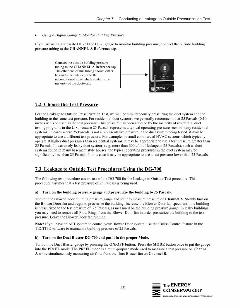
Chapter 7 Conducting a Leakage to Outside Pressurization Test
30 The ENERGYCONSERVATORYDIAGNOSTIC TOOLS TO MEASURE BUILDING PERFORMANCE
• Using a Digital Gauge to Monitor Building Pressure:
If you are using a separate DG-700 or DG-3 gauge to monitor building pressure, connect the outside buildingpressure tubing to the CHANNEL A Reference tap.
a)
b)
Connect the outside building pressuretubing to the CHANNEL A Reference tap.The other end of this tubing should eitherbe run to the outside, or to theunconditioned zone which contains themajority of the ductwork.
7.2 Choose the Test Pressure
For the Leakage to Outside Pressurization Test, we will be simultaneously pressuring the duct system and thebuilding to the same test pressure. For residential duct systems, we generally recommend that 25 Pascals (0.10inches w.c.) be used as the test pressure. This pressure has been adopted by the majority of residential ducttesting programs in the U.S. because 25 Pascals represents a typical operating pressure seen in many residentialsystems. In cases where 25 Pascals is not a representative pressure in the duct system being tested, it may beappropriate to use a different test pressure. For example, in small commercial HVAC systems which typicallyoperate at higher duct pressures than residential systems, it may be appropriate to use a test pressure greater than25 Pascals. In extremely leaky duct systems (e.g. more than 600 cfm of leakage at 25 Pascals), such as ductsystems found in many basement style houses, the typical operating pressures in the duct system may besignificantly less than 25 Pascals. In this case it may be appropriate to use a test pressure lower than 25 Pascals.
7.3 Leakage to Outside Test Procedures Using the DG-700
The following test procedure covers use of the DG-700 for the Leakage to Outside Test procedure. Thisprocedure assumes that a test pressure of 25 Pascals is being used.
Turn on the building pressure gauge and pressurize the building to 25 Pascals.
Turn on the Blower Door building pressure gauge and set it to measure pressure on Channel A. Slowly turn onthe Blower Door fan and begin to pressurize the building. Increase the Blower Door fan speed until the buildingis pressurized to the test pressure of 25 Pascals, as measured on the building pressure gauge. In leaky buildings,you may need to remove all Flow Rings from the Blower Door fan in order pressurize the building to the testpressure. Leave the Blower Door fan running.
Note: If you have an APT system to control your Blower Door system, use the Cruise Control feature in theTECTITE software to maintain a building pressure of 25 Pascals.
Turn on the Duct Blaster DG-700 and put it in the proper Mode.
Turn on the Duct Blaster gauge by pressing the ON/OFF button. Press the MODE button once to put the gaugeinto the PR/ FL mode. The PR/ FL mode is a multi-purpose mode used to measure a test pressure on ChannelA while simultaneously measuring air flow from the Duct Blaster fan on Channel B.
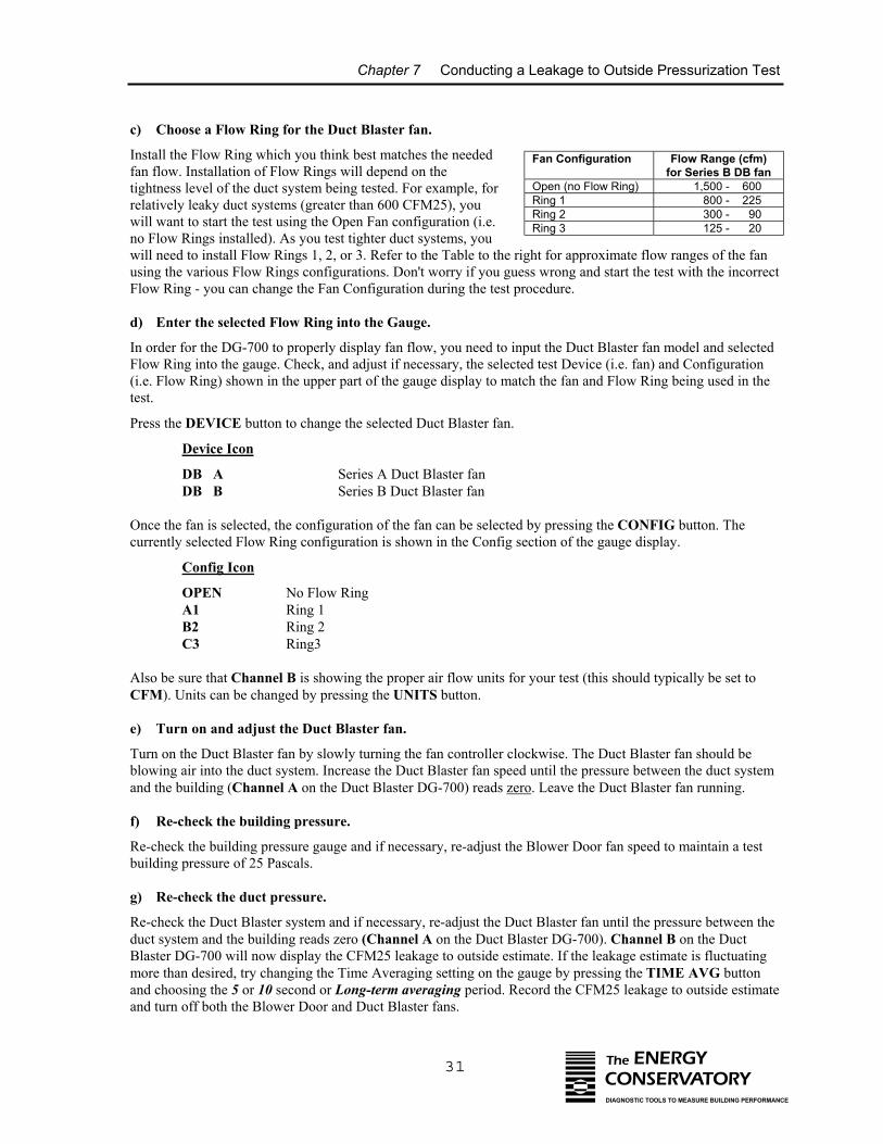
Chapter 7 Conducting a Leakage to Outside Pressurization Test
31
c) Choose a Flow Ring for the Duct Blaster fan.
Install the Flow Ring which you think best matches the neededfan flow. Installation of Flow Rings will depend on thetightness level of the duct system being tested. For example, forrelatively leaky duct systems (greater than 600 CFM25), youwill want to start the test using the Open Fan configuration (i.e.no Flow Rings installed). As you test tighter duct systems, youwill need to install Flow Rings 1, 2, or 3. Refer to the Table to the rigusing the various Flow Rings configurations. Don't worry if you guesFlow Ring - you can change the Fan Configuration during the test pr
d) Enter the selected Flow Ring into the Gauge.
In order for the DG-700 to properly display fan flow, you need to inpFlow Ring into the gauge. Check, and adjust if necessary, the selecte(i.e. Flow Ring) shown in the upper part of the gauge display to matctest.
Press the DEVICE button to change the selected Duct Blaster fan.
Device Icon
DB A Series A Duct Blaster fanDB B Series B Duct Blaster fan
Once the fan is selected, the configuration of the fan can be selected currently selected Flow Ring configuration is shown in the Config se
Config Icon
OPEN No Flow RingA1 Ring 1B2 Ring 2C3 Ring3
Also be sure that Channel B is showing the proper air flow units forCFM). Units can be changed by pressing the UNITS button.
e) Turn on and adjust the Duct Blaster fan.
Turn on the Duct Blaster fan by slowly turning the fan controller cloblowing air into the duct system. Increase the Duct Blaster fan speedand the building (Channel A on the Duct Blaster DG-700) reads zero
f) Re-check the building pressure.
Re-check the building pressure gauge and if necessary, re-adjust the building pressure of 25 Pascals.
g) Re-check the duct pressure.
Re-check the Duct Blaster system and if necessary, re-adjust the Ducduct system and the building reads zero (Channel A on the Duct BlaBlaster DG-700 will now display the CFM25 leakage to outside estimmore than desired, try changing the Time Averaging setting on the gand choosing the 5 or 10 second or Long-term averaging period. Reand turn off both the Blower Door and Duct Blaster fans.
Fan Configuration
Flow Range (cfm)for Series B DB fan
Open (no Flow Ring) 1,500 - 600Ring 1 800 - 225Ring 2 300 - 90Ring 3 125 - 20
The ENERGYCONSERVATORYDIAGNOSTIC TOOLS TO MEASURE BUILDING PERFORMANCE
ht for approximate flow ranges of the fans wrong and start the test with the incorrect
ocedure.
ut the Duct Blaster fan model and selectedd test Device (i.e. fan) and Configurationh the fan and Flow Ring being used in the
by pressing the CONFIG button. Thection of the gauge display.
your test (this should typically be set to
ckwise. The Duct Blaster fan should be until the pressure between the duct system. Leave the Duct Blaster fan running.
Blower Door fan speed to maintain a test
t Blaster fan until the pressure between thester DG-700). Channel B on the Ductate. If the leakage estimate is fluctuating
auge by pressing the TIME AVG buttoncord the CFM25 leakage to outside estimate
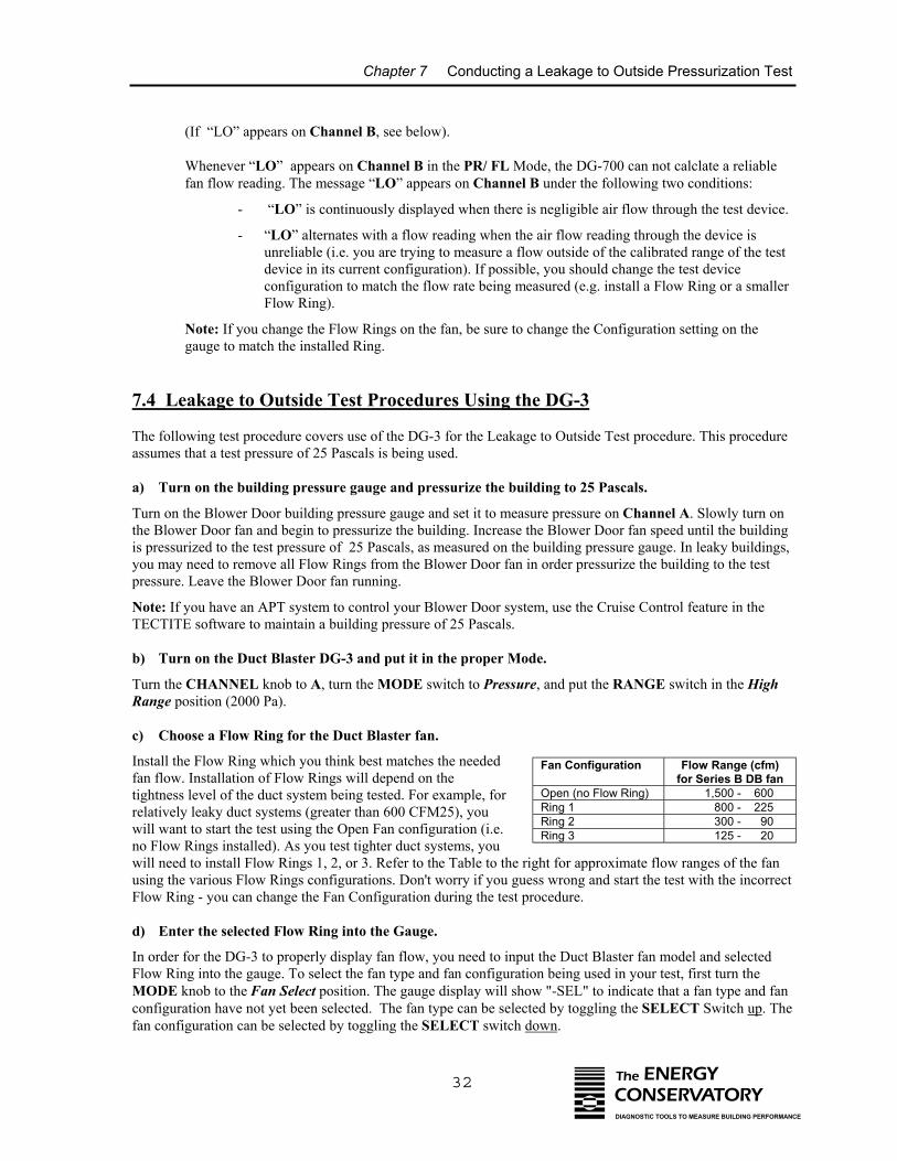
Chapter 7 Conducting a Leakage to Outside Pressurization Test
32
(If “LO” appears on Channel B, see below).
Whenever “LO” appears on Channel B in the PR/ FL Mode, the DG-700 can not calclate a reliablefan flow reading. The message “LO” appears on Channel B under the following two conditions:
- “LO” is continuously displayed when there is negligible air flow through the test device.
- “LO” alternates with a flow reading when the air flow reading through the device isunreliable (i.e. you are trying to measure a flow outside of the calibrated range of the testdevice in its current configuration). If possible, you should change the test deviceconfiguration to match the flow rate being measured (e.g. install a Flow Ring or a smallerFlow Ring).
Note: If you change the Flow Rings on the fan, be sure to change the Configuration setting on thegauge to match the installed Ring.
7.4 Leakage to Outside Test Procedures Using the DG-3
The following test procedure covers use of the DG-3 for the Leakage to Outside Test procedure. This procedureassumes that a test pressure of 25 Pascals is being used.
a) Turn on the building pressure gauge and pressurize the building to 25 Pascals.
Turn on the Blower Door building pressure gauge and set it to measure pressure on Channel A. Slowly turn onthe Blower Door fan and begin to pressurize the building. Increase the Blower Door fan speed until the buildingis pressurized to the test pressure of 25 Pascals, as measured on the building pressure gauge. In leaky buildings,you may need to remove all Flow Rings from the Blower Door fan in order pressurize the building to the testpressure. Leave the Blower Door fan running.
Note: If you have an APT system to control your Blower Door system, use the Cruise Control feature in theTECTITE software to maintain a building pressure of 25 Pascals.
b) Turn on the Duct Blaster DG-3 and put it in the proper Mode.
Turn the CHANNEL knob to A, turn the MODE switch to Pressure, and put the RANGE switch in the HighRange position (2000 Pa).
c) Choose a Flow Ring for the Duct Blaster fan.
Install the Flow Ring which you think best matches the neededfan flow. Installation of Flow Rings will depend on thetightness level of the duct system being tested. For example, forrelatively leaky duct systems (greater than 600 CFM25), youwill want to start the test using the Open Fan configuration (i.e.no Flow Rings installed). As you test tighter duct systems, youwill need to install Flow Rings 1, 2, or 3. Refer to the Table to the rigusing the various Flow Rings configurations. Don't worry if you guesFlow Ring - you can change the Fan Configuration during the test pr
d) Enter the selected Flow Ring into the Gauge.
In order for the DG-3 to properly display fan flow, you need to inputFlow Ring into the gauge. To select the fan type and fan configuratioMODE knob to the Fan Select position. The gauge display will showconfiguration have not yet been selected. The fan type can be selectefan configuration can be selected by toggling the SELECT switch do
Fan Configuration
Flow Range (cfm)for Series B DB fan
Open (no Flow Ring) 1,500 - 600Ring 1 800 - 225Ring 2 300 - 90Ring 3 125 - 20
The ENERGYCONSERVATORYDIAGNOSTIC TOOLS TO MEASURE BUILDING PERFORMANCE
ht for approximate flow ranges of the fans wrong and start the test with the incorrect
ocedure.
the Duct Blaster fan model and selectedn being used in your test, first turn the "-SEL" to indicate that a fan type and fand by toggling the SELECT Switch up. Thewn.
Chapter 7 Conducting a Leakage to Outside Pressurization Test
33 The ENERGYCONSERVATORYDIAGNOSTIC TOOLS TO MEASURE BUILDING PERFORMANCE
If the DisplayShows Description
-SEL Begin fan type selection by toggling the SELECT switch up twice.
8-0 This indicates that you have chosen the Series B Duct Blaster fan, and that the fan is in the"Open" inlet configuration (i.e. no Flow Rings installed).
To change the fan inlet configuration for the Duct Blaster fan, toggle the SELECT switch down.
8-1 Series B Duct Blaster fan with Ring 1 installed. 8-2 Series B Duct Blaster fan with Ring 2 installed. 8-3 Series B Duct Blaster fan with Ring 3 installed.
e) Turn on and adjust the Duct Blaster fan.
Turn on the Duct Blaster fan by slowly turning the fan controller clockwise. The Duct Blaster fan should beblowing air into the duct system. Increase the Duct Blaster fan speed until the pressure between the duct systemand the building (Channel A on the Duct Blaster DG-3) reads zero. Leave the Duct Blaster fan running.
f) Re-check the building pressure.
Re-check the building pressure gauge and if necessary, re-adjust the Blower Door fan speed to maintain a testbuilding pressure of 25 Pascals.
g) Re-check the duct pressure.
Re-check the Duct Blaster system and if necessary, re-adjust the Duct Blaster fan until the pressure between theduct system and the building reads zero (Channel A on the Duct Blaster DG-3). After re-adjusting the fanspeed, turn the CHANNEL knob to Channel B, and turn the MODE switch to Flow. The gauge will nowdisplay the CFM25 leakage to outside estimate. If the gauge display is fluctuating too much to determine thereading, try changing the Time Averaging setting on the gauge by turning the MODE Switch to Time Select,choosing the 5 or 10 second or Long-term average, and then returning to the Flow mode. Record the CFM25leakage to outside estimate and turn off both the Blower Door and Duct Blaster fans.
(If the CFM flow reading on Channel B is blinking, see below):
- The CFM flow reading on Channel B will blink when the air flow reading through the fan isunreliable (i.e. you are trying to measure a flow outside of the calibrated range of the test device inits current configuration). If possible, you should change the fan configuration to match the flowrate being measured (e.g. install a Flow Ring or a smaller Flow Ring).
- If you change Flow Rings, be sure to use the Fan Select feature to update the gauge with the newFlow Ring installed before reconducting the test.
7.5 What If You Can Not Pressurize the Building to the Test Pressure with theBlower Door Fan?
If the Blower Door system is unable to pressurize the building to the test pressure because one of the FlowRings was installed on the Blower Door fan, remove the Flow Ring and repeat the test. If you are not able topressurize the building to the test pressure because the building is too leaky, then you will need to conduct thetest at the highest achievable building pressure and use the Can't Reach Pressure Factors below to estimate thefinal duct leakage rate.
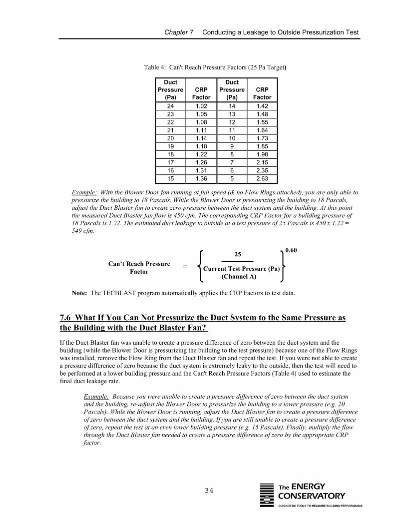
Chapter 7 Conducting a Leakage to Outside Pressurization Test
Table 4: Can't Reach Pressure Factors (25 Pa Target)
Example: With the Blower Door pressurize the building to 18 Pascadjust the Duct Blaster fan to crethe measured Duct Blaster fan flo18 Pascals is 1.22. The estimated549 cfm.
Note: The TECBLAST program
7.6 What If You Can Not Pthe Building with the Duct B
If the Duct Blaster fan was unable to cbuilding (while the Blower Door is prewas installed, remove the Flow Ring fa pressure difference of zero because tbe performed at a lower building pressfinal duct leakage rate.
Example: Because you wereand the building, re-adjust thPascals). While the Blower Dof zero between the duct systeof zero, repeat the test at an ethrough the Duct Blaster fan factor.
Can’t Reach PressFactor
P
Duct Ductressure CRP Pressure CRP(Pa) Factor (Pa) Factor24 1.02 14 1.4223 1.05 13 1.4822 1.08 12 1.5521 1.11 11 1.6420 1.14 10 1.7319 1.18 9 1.8518 1.22 8 1.9817 1.26 7 2.1516 1.31 6 2.3515 1.36 5 2.63
34 The ENERGYCONSERVATORYDIAGNOSTIC TOOLS TO MEASURE BUILDING PERFORMANCE
fan running at full speed (& no Flow Rings attached), you are only able toals. While the Blower Door is pressurizing the building to 18 Pascals,
ate zero pressure between the duct system and the building. At this pointw is 450 cfm. The corresponding CRP Factor for a building pressure of duct leakage to outside at a test pressure of 25 Pascals is 450 x 1.22 =
automatically applies the CRP Factors to test data.
ressurize the Duct System to the Same Pressure aslaster Fan?
reate a pressure difference of zero between the duct system and thessurizing the building to the test pressure) because one of the Flow Rings
rom the Duct Blaster fan and repeat the test. If you were not able to createhe duct system is extremely leaky to the outside, then the test will need toure and the Can't Reach Pressure Factors (Table 4) used to estimate the
unable to create a pressure difference of zero between the duct systeme Blower Door to pressurize the building to a lower pressure (e.g. 20oor is running, adjust the Duct Blaster fan to create a pressure differencem and the building. If you are still unable to create a pressure differenceven lower building pressure (e.g. 15 Pascals). Finally, multiply the flowneeded to create a pressure difference of zero by the appropriate CRP
25
Current Test Pressure (Pa) (Channel A)
0.60
ure =
Chapter 7 Conducting a Leakage to Outside Pressurization Test
35 The ENERGYCONSERVATORYDIAGNOSTIC TOOLS TO MEASURE BUILDING PERFORMANCE
For example, with the Blower Door pressurizing the building to 15 Pascals, the flow through the DuctBlaster fan needed to create a pressure difference of zero (between the duct system and the building) is1,200 cfm. The corresponding CRP Factor for a building pressure of 15 Pascals is 1.36. The estimatedduct leakage to outside at a test pressure of 25 Pascals is 1200 x 1.36 = 1,632 cfm.
Note: The TECBLAST program will automatically apply the CRP Factors to test data.
7.7 Before Leaving the Building
Be sure you have returned the building to its original condition before leaving. This includes removing anytemporary register seals, turning HVAC controls to their original settings and closing access doors or ventsopened during the test. In addition, it is highly recommended that the test procedures outlined in Chapters 14and 15 be performed before leaving the building.
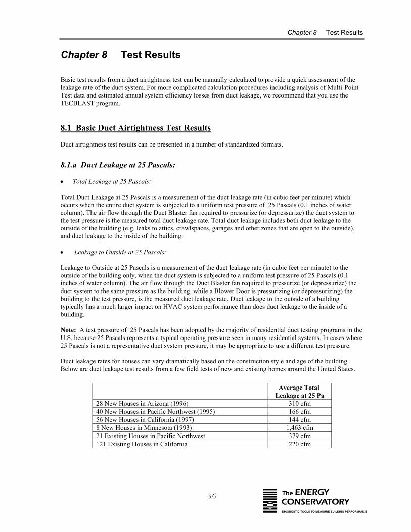
Chapter 8 Test Results
Chapter 8 Test Results
Basic test results from a duct airtightness test can be manually calculated to provide a quick assessment of theleakage rate of the duct system. For more complicated calculation procedures including analysis of Multi-PointTest data and estimated annual system efficiency losses from duct leakage, we recommend that you use theTECBLAST program.
8.1 Basic Duct Airtightness Test Results
Duct airtightness test results can be presented in a number of standardized formats.
8.1.a Duct Leakage at 25 Pascals:
• Total Leakage at 25 Pascals:
Total Duct Leakage at 25 Pascals is a measurement of the duct leakage rate (in cubic feet per minute) whichoccurs when the entire duct system is subjected to a uniform test pressure of 25 Pascals (0.1 inches of watercolumn). The air flow through the Duct Blaster fan required to pressurize (or depressurize) the duct system tothe test pressure is the measured total duct leakage rate. Total duct leakage includes both duct leakage to theoutside of the building (e.g. leaks to attics, crawlspaces, garages and other zones that are open to the outside),and duct leakage to the inside of the building.
• Leakage to Outside at 25 Pascals:
Leakage to Outside at 25 Pascals is a measurement of the duct leakage rate (in cubic feet per minute) to theoutside of the building only, when the duct system is subjected to a uniform test pressure of 25 Pascals (0.1inches of water column). The air flow through the Duct Blaster fan required to pressurize (or depressurize) theduct system to the same pressure as the building, while a Blower Door is pressurizing (or depressurizing) thebuilding to the test pressure, is the measured duct leakage rate. Duct leakage to the outside of a buildingtypically has a much larger impact on HVAC system performance than does duct leakage to the inside of abuilding.
Note: A test pressure of 25 Pascals has been adopted by the majority of residential duct testing programs in theU.S. because 25 Pascals represents a typical operating pressure seen in many residential systems. In cases where25 Pascals is not a representative duct system pressure, it may be appropriate to use a different test pressure.
Duct leakage rates for houses can vary dramatically based on the construction style and age of the building. Below are duct leakage test results from a few field tests of new and existing homes around the United States.
Average Total Leakage at 25 Pa
28 New Houses in Arizona (1996) 310 cfm40 New Houses in Pacific Northwest (1995) 166 cfm56 New Houses in California (1997) 144 cfm8 New Houses in Minnesota (1993) 1,463 cfm21 Existing Houses in Pacific Northwest 379 cfm121 Existing Houses in California 220 cfm
36 The ENERGYCONSERVATORYDIAGNOSTIC TOOLS TO MEASURE BUILDING PERFORMANCE
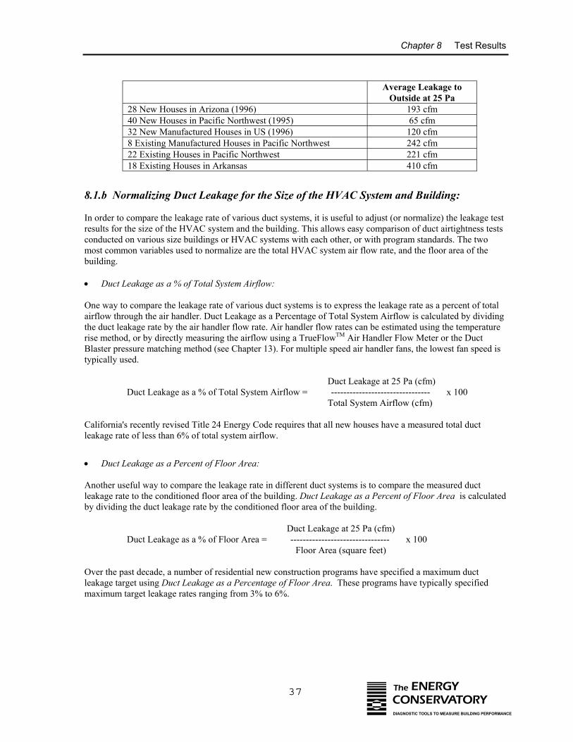
Chapter 8 Test Results
8.1.b No
In order toresults forconductedmost commbuilding.
• Duct L
One way tairflow thrthe duct lerise methoBlaster pretypically u
Californialeakage ra
• Duct L
Another uleakage raby dividin
Over the pleakage tamaximum
Average Leakage toOutside at 25 Pa
28 New Houses in Arizona (1996) 193 cfm40 New Houses in Pacific Northwest (1995) 65 cfm32 New Manufactured Houses in US (1996) 120 cfm8 Existing Manufactured Houses in Pacific Northwest 242 cfm22 Existing Houses in Pacific Northwest 221 cfm18 Existing Houses in Arkansas 410 cfm
37 The ENERGYCONSERVATORYDIAGNOSTIC TOOLS TO MEASURE BUILDING PERFORMANCE
rmalizing Duct Leakage for the Size of the HVAC System and Building:
compare the leakage rate of various duct systems, it is useful to adjust (or normalize) the leakage test the size of the HVAC system and the building. This allows easy comparison of duct airtightness tests on various size buildings or HVAC systems with each other, or with program standards. The two
on variables used to normalize are the total HVAC system air flow rate, and the floor area of the
eakage as a % of Total System Airflow:
o compare the leakage rate of various duct systems is to express the leakage rate as a percent of totalough the air handler. Duct Leakage as a Percentage of Total System Airflow is calculated by dividingakage rate by the air handler flow rate. Air handler flow rates can be estimated using the temperatured, or by directly measuring the airflow using a TrueFlowTM Air Handler Flow Meter or the Ductssure matching method (see Chapter 13). For multiple speed air handler fans, the lowest fan speed issed.
Duct Leakage at 25 Pa (cfm) Duct Leakage as a % of Total System Airflow = -------------------------------- x 100 Total System Airflow (cfm)
's recently revised Title 24 Energy Code requires that all new houses have a measured total ductte of less than 6% of total system airflow.
eakage as a Percent of Floor Area:
seful way to compare the leakage rate in different duct systems is to compare the measured ductte to the conditioned floor area of the building. Duct Leakage as a Percent of Floor Area is calculatedg the duct leakage rate by the conditioned floor area of the building.
Duct Leakage at 25 Pa (cfm) Duct Leakage as a % of Floor Area = -------------------------------- x 100 Floor Area (square feet)
ast decade, a number of residential new construction programs have specified a maximum ductrget using Duct Leakage as a Percentage of Floor Area. These programs have typically specified target leakage rates ranging from 3% to 6%.
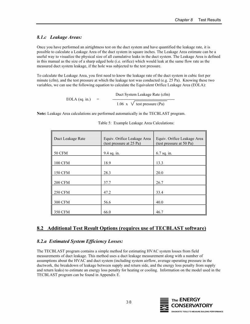
Chapter 8 Test Results
38 The ENERGYCONSERVATORYDIAGNOSTIC TOOLS TO MEASURE BUILDING PERFORMANCE
8.1.c Leakage Areas:
Once you have performed an airtightness test on the duct system and have quantified the leakage rate, it ispossible to calculate a Leakage Area of the duct system in square inches. The Leakage Area estimate can be auseful way to visualize the physical size of all cumulative leaks in the duct system. The Leakage Area is definedin this manual as the size of a sharp edged hole (i.e. orifice) which would leak at the same flow rate as themeasured duct system leakage, if the hole was subjected to the test pressure.
To calculate the Leakage Area, you first need to know the leakage rate of the duct system in cubic feet perminute (cfm), and the test pressure at which the leakage test was conducted (e.g. 25 Pa). Knowing these twovariables, we can use the following equation to calculate the Equivalent Orifice Leakage Area (EOLA):
Duct System Leakage Rate (cfm)EOLA (sq. in.) = ----------------------------------------------
1.06 x test pressure (Pa)
Note: Leakage Area calculations are performed automatically in the TECBLAST program.
Table 5: Example Leakage Area Calculations:
Duct Leakage Rate Equiv. Orifice Leakage Area(test pressure at 25 Pa)
Equiv. Orifice Leakage Area(test pressure at 50 Pa)
50 CFM 9.4 sq. in. 6.7 sq. in.
100 CFM 18.9 13.3
150 CFM 28.3 20.0
200 CFM 37.7 26.7
250 CFM 47.2 33.4
300 CFM 56.6 40.0
350 CFM 66.0 46.7
8.2 Additional Test Result Options (requires use of TECBLAST software)
8.2.a Estimated System Efficiency Losses:
The TECBLAST program contains a simple method for estimating HVAC system losses from fieldmeasurements of duct leakage. This method uses a duct leakage measurement along with a number ofassumptions about the HVAC and duct system (including system airflow, average operating pressure in theductwork, the breakdown of leakage between supply and return side, and the energy loss penalty from supplyand return leaks) to estimate an energy loss penalty for heating or cooling. Information on the model used in theTECBLAST program can be found in Appendix E.
Chapter 8 Test Results
39 The ENERGYCONSERVATORYDIAGNOSTIC TOOLS TO MEASURE BUILDING PERFORMANCE
Note: Because duct leakage loss calculations are extremely complex, the estimation technique in TECBLASTshould be used with caution and should be viewed only as a rough estimate of the magnitude of losses possible.The leakage rate of a duct system determined using the airtightness test procedures listed in this manual maydiffer from the leakage rates occurring in the duct system under actual operating conditions. In addition, the ductleakage loss estimates do not include many important but complex impacts on system efficiency including latentload impacts, heat pump strip heating impacts, conduction losses, increases in infiltration from dominant ductleakage, or interactions of leakage on mechanical operating efficiencies, all of which can be significantdepending on the type and location of the system being tested. We do not recommend that this simple model beused for research purposes, program design studies or impact evaluations. More sophisticated duct leakage lossmodels are available and better suited to these needs. Listed below are three references to other duct leakageloss models:
ASHRAE Standard 152P, Method of Test for Determining the Design and Seasonal Efficiencies ofResidential Thermal Distribution Systems, ASHRAE, Atlanta GA, May 1999.
Development of a Practical Method for Estimating the Thermal Efficiency of Residential ForcedAir Distribution Systems, EPRI, Palo Alto CA, January 1997.
Improvements to ASHRAE Standard 152P, Paul Francisco and Larry Palmer, Ecotope, Seattle WA,June 1999.
8.2.b Duct Leakage Curve:
Once the duct leakage test data has been collected and entered into the TECBLAST program, it is plotted on aTest Graph and a "best-fit" regression line (called the Duct Leakage Curve) is drawn through the plotted data. The Duct Leakage Curve can be used to estimate the leakage rate of the duct system at any pressure. If youconduct a single point test, TECBLAST assumes an exponent (n) of 0.60 in its calculation procedures.
The Duct Leakage Curve is defined by the variables Coefficient (C) and Exponent (n) in the following equation:
Q = C x P^n
where: Q is leakage into (or out of) the duct system (in CFM). C is the Coefficient. P is the pressure difference between inside and outside of the duct system (in Pascals). n is the Exponent.
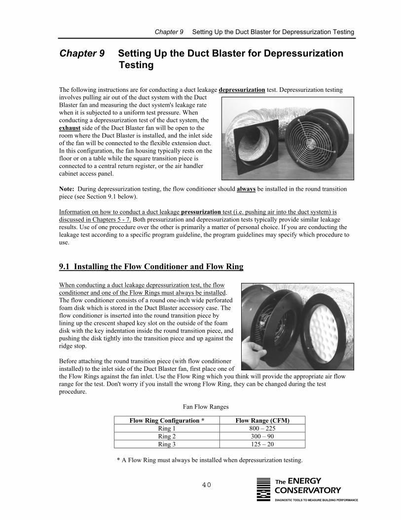
Chapter 9 Setting Up the Duct Blaster for Depressurization Testing
40 The ENERGYCONSERVATORYDIAGNOSTIC TOOLS TO MEASURE BUILDING PERFORMANCE
Chapter 9 Setting Up the Duct Blaster for Depressurization Testing
The following instructions are for conducting a duct leakage depressurization test. Depressurization testinginvolves pulling air out of the duct system with the DuctBlaster fan and measuring the duct system's leakage ratewhen it is subjected to a uniform test pressure. Whenconducting a depressurization test of the duct system, theexhaust side of the Duct Blaster fan will be open to theroom where the Duct Blaster is installed, and the inlet sideof the fan will be connected to the flexible extension duct.In this configuration, the fan housing typically rests on thefloor or on a table while the square transition piece isconnected to a central return register, or the air handlercabinet access panel.
Note: During depressurization testing, the flow conditioner should always be installed in the round transitionpiece (see Section 9.1 below).
Information on how to conduct a duct leakage pressurization test (i.e. pushing air into the duct system) isdiscussed in Chapters 5 - 7. Both pressurization and depressurization tests typically provide similar leakageresults. Use of one procedure over the other is primarily a matter of personal choice. If you are conducting theleakage test according to a specific program guideline, the program guidelines may specify which procedure touse.
9.1 Installing the Flow Conditioner and Flow Ring
When conducting a duct leakage depressurization test, the flowconditioner and one of the Flow Rings must always be installed. The flow conditioner consists of a round one-inch wide perforatedfoam disk which is stored in the Duct Blaster accessory case. Theflow conditioner is inserted into the round transition piece bylining up the crescent shaped key slot on the outside of the foamdisk with the key indentation inside the round transition piece, andpushing the disk tightly into the transition piece and up against theridge stop.
Before attaching the round transition piece (with flow conditionerinstalled) to the inlet side of the Duct Blaster fan, first place one ofthe Flow Rings against the fan inlet. Use the Flow Ring which you think will provide the appropriate air flowrange for the test. Don't worry if you install the wrong Flow Ring, they can be changed during the testprocedure.
Fan Flow Ranges
Flow Ring Configuration * Flow Range (CFM)Ring 1 800 – 225Ring 2 300 – 90Ring 3 125 – 20
* A Flow Ring must always be installed when depressurization testing.
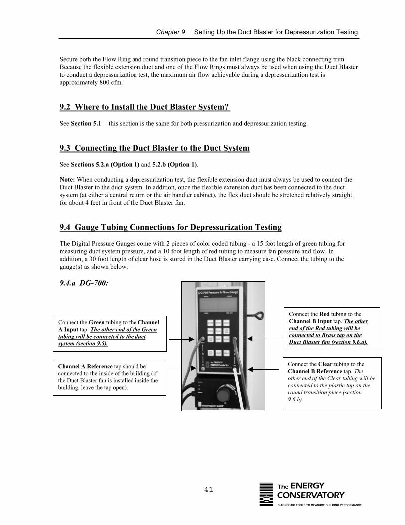
Chapter 9 Setting Up the Duct Blaster for Depressurization Testing
41 The ENERGYCONSERVATORYDIAGNOSTIC TOOLS TO MEASURE BUILDING PERFORMANCE
Secure both the Flow Ring and round transition piece to the fan inlet flange using the black connecting trim.Because the flexible extension duct and one of the Flow Rings must always be used when using the Duct Blasterto conduct a depressurization test, the maximum air flow achievable during a depressurization test isapproximately 800 cfm.
9.2 Where to Install the Duct Blaster System?
See Section 5.1 - this section is the same for both pressurization and depressurization testing.
9.3 Connecting the Duct Blaster to the Duct System
See Sections 5.2.a (Option 1) and 5.2.b (Option 1).
Note: When conducting a depressurization test, the flexible extension duct must always be used to connect theDuct Blaster to the duct system. In addition, once the flexible extension duct has been connected to the ductsystem (at either a central return or the air handler cabinet), the flex duct should be stretched relatively straightfor about 4 feet in front of the Duct Blaster fan.
9.4 Gauge Tubing Connections for Depressurization Testing
The Digital Pressure Gauges come with 2 pieces of color coded tubing - a 15 foot length of green tubing formeasuring duct system pressure, and a 10 foot length of red tubing to measure fan pressure and flow. Inaddition, a 30 foot length of clear hose is stored in the Duct Blaster carrying case. Connect the tubing to thegauge(s) as shown below:
9.4.a DG-700:
Connect the Green tubing to the ChannelA Input tap. The other end of the Greentubing will be connected to the ductsystem (section 9.5).
Connect the Red tubing to theChannel B Input tap. The otherend of the Red tubing will beconnected to Brass tap on theDuct Blaster fan (section 9.6.a).
Channel A Reference tap should beconnected to the inside of the building (ifthe Duct Blaster fan is installed inside thebuilding, leave the tap open).
Connect the Clear tubing to theChannel B Reference tap. Theother end of the Clear tubing will beconnected to the plastic tap on theround transition piece (section9.6.b).
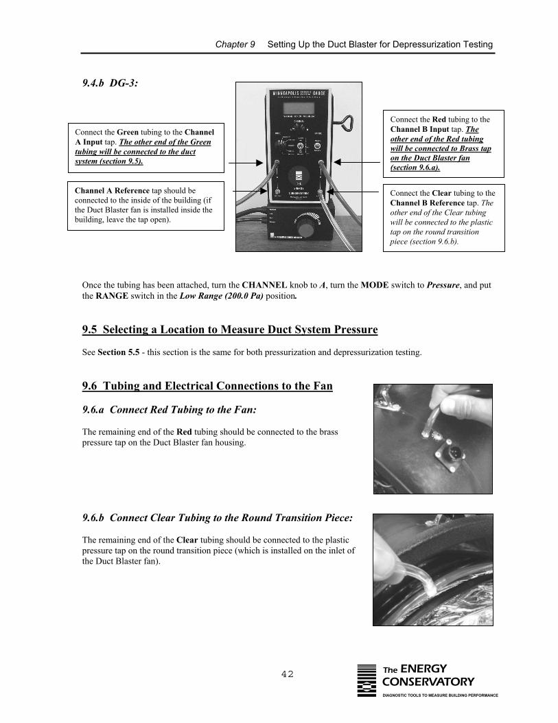
Chapter 9 Setting Up the Duct Blaster for Depressurization Testing
42 The ENERGYCONSERVATORYDIAGNOSTIC TOOLS TO MEASURE BUILDING PERFORMANCE
9.4.b DG-3:
Connect the Green tubing to the ChannelA Input tap. The other end of the Greentubing will be connected to the ductsystem (section 9.5).
Channel A Reference tap should beconnected to the inside of the building (ifthe Duct Blaster fan is installed inside thebuilding, leave the tap open).
Connect the Red tubing to theChannel B Input tap. Theother end of the Red tubingwill be connected to Brass tapon the Duct Blaster fan(section 9.6.a).
Connect the Clear tubing to theChannel B Reference tap. Theother end of the Clear tubingwill be connected to the plastictap on the round transitionpiece (section 9.6.b).
Once the tubing has been attached, turn the CHANNEL knob to A, turn the MODE switch to Pressure, and putthe RANGE switch in the Low Range (200.0 Pa) position.
9.5 Selecting a Location to Measure Duct System Pressure
See Section 5.5 - this section is the same for both pressurization and depressurization testing.
9.6 Tubing and Electrical Connections to the Fan
9.6.a Connect Red Tubing to the Fan:
The remaining end of the Red tubing should be connected to the brasspressure tap on the Duct Blaster fan housing.
9.6.b Connect Clear Tubing to the Round Transition Piece:
The remaining end of the Clear tubing should be connected to the plastic pressure tap on the round transition piece (which is installed on the inlet ofthe Duct Blaster fan).
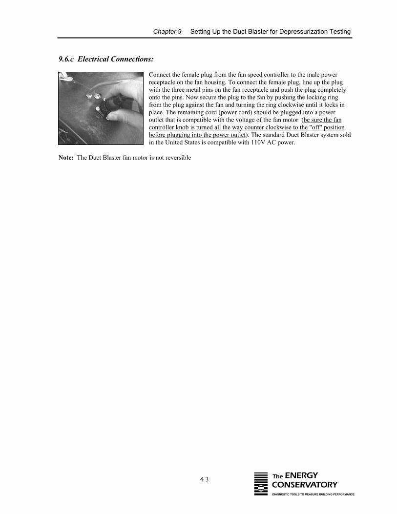
Chapter 9 Setting Up the Duct Blaster for Depressurization Testing
43 The ENERGYCONSERVATORYDIAGNOSTIC TOOLS TO MEASURE BUILDING PERFORMANCE
9.6.c Electrical Connections:
Connect the female plug from the fan speed controller to the male powerreceptacle on the fan housing. To connect the female plug, line up the plugwith the three metal pins on the fan receptacle and push the plug completelyonto the pins. Now secure the plug to the fan by pushing the locking ringfrom the plug against the fan and turning the ring clockwise until it locks inplace. The remaining cord (power cord) should be plugged into a poweroutlet that is compatible with the voltage of the fan motor (be sure the fancontroller knob is turned all the way counter clockwise to the "off" positionbefore plugging into the power outlet). The standard Duct Blaster system soldin the United States is compatible with 110V AC power.
Note: The Duct Blaster fan motor is not reversible
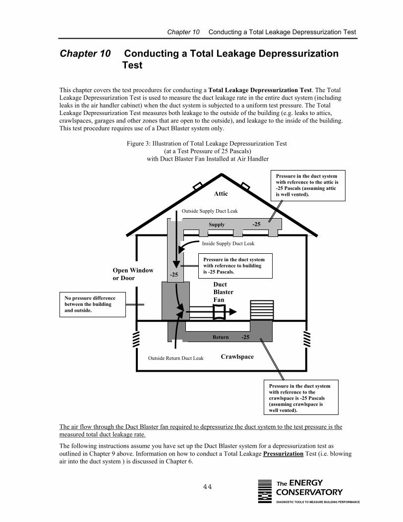
Chapter 10 Conducting a Total Leakage Depressurization Test
44 The ENERGYCONSERVATORYDIAGNOSTIC TOOLS TO MEASURE BUILDING PERFORMANCE
Chapter 10 Conducting a Total Leakage Depressurization Test
This chapter covers the test procedures for conducting a Total Leakage Depressurization Test. The Total Leakage Depressurization Test is used to measure the duct leakage rate in the entire duct system (includingleaks in the air handler cabinet) when the duct system is subjected to a uniform test pressure. The Total Leakage Depressurization Test measures both leakage to the outside of the building (e.g. leaks to attics,crawlspaces, garages and other zones that are open to the outside), and leakage to the inside of the building.This test procedure requires use of a Duct Blaster system only.
Figure 3: Illustration of Total Leakage Depressurization Test (at a Test Pressure of 25 Pascals)
with Duct Blaster Fan Installed at Air Handler
The air flow through the Duct Blaster fan required to depressurize the duct system to the test pressure is themeasured total duct leakage rate.
The following instructions assume you have set up the Duct Blaster system for a depressurization test asoutlined in Chapter 9 above. Information on how to conduct a Total Leakage Pressurization Test (i.e. blowingair into the duct system ) is discussed in Chapter 6.
Attic
Return -25
DuctBlasterFan
Open Windowor Door
Inside Supply Duct Leak
Outside Supply Duct Leak
Outside Return Duct Leak
Supply -25
Crawlspace
Pressure in the duct systemwith reference to buildingis -25 Pascals.
No pressure differencebetween the buildingand outside.
-25
Pressure in the duct systemwith reference to the attic is-25 Pascals (assuming atticis well vented).
Pressure in the duct systemwith reference to thecrawlspace is -25 Pascals(assuming crawlspace iswell vented).
Chapter 10 Conducting a Total Leakage Depressurization Test
45 The ENERGYCONSERVATORYDIAGNOSTIC TOOLS TO MEASURE BUILDING PERFORMANCE
Note: It is possible to separately measure total supply and return duct leaks by installing a temporary barrier ineither the supply or return opening to the air handler cabinet. With a temporary barrier in place, each side of theduct system can be tested independently. It is also possible to separately measure supply and return leakagebefore the air handler or furnace unit has been installed.
10.1 Final Preparations (Open a Door or Window to the Outside)
• Open a door or window between the building and outside to prevent changes in building pressure when theDuct Blaster fan is running. We want to prevent changes in building pressures because the pressuredifference across duct leaks will be different for leaks to the inside of the building compared with leaks tothe outside. Changes in building pressure could be caused by:
⇒ If the Duct Blaster is installed inside the building and there are large leaks between the duct system
and outside, depressurizing the duct system may pressurize the building relative to outside.
⇒ If the Duct Blaster is installed in an unconditioned space (attic, garage or crawlspace air handler),depressurizing the duct system may depressurize the building relative to outside.
10.2 Choosing the Test Pressure and Number of Test Readings
10.2.a Test Pressure:
For residential duct systems, we generally recommend that -25 Pascals (-0.10 inches w.c.) be used as the testpressure. This pressure has been adopted by the majority of residential duct testing programs in the U.S. because25 Pascals represents a typical operating pressure seen in many residential systems. In cases where 25 Pascals isnot a representative pressure in the duct system being tested, it may be appropriate to use a different testpressure. For example, in small commercial HVAC systems which typically operate at higher duct pressuresthan residential systems, it may be appropriate to use a test pressure greater than 25 Pascals. In extremely leakyduct systems, such as duct systems found in many basement style houses, typical operating pressures in the ductsystem may be significantly less than 25 Pascals. In this case it may be appropriate to use a test pressure lowerthan 25 Pascals.
10.2.b Number of Test Readings:
The most common test procedure is to conduct a One-Point Test to assess duct airtightness. The One-Point Testutilizes a single measurement of Duct Blaster fan flow needed to produce the test pressure in the duct system.The One-Point Test provides a quick and simple way to measure duct leakage without the need to have acomputer to analyze the test data (although a computer program like TECBLAST can still be useful to generatereports and store data).
The Multi-Point Test procedure involves testing the duct system over a range of test pressures and analyzing thedata using a duct airtightness test computer program (e.g. TECBLAST). For example, a typical Multi-Point Testof a residential duct system includes taking measurements at 5 different test pressures including -35 Pascals, -30, -25, -20 and -15 Pascals. Making multiple measurements allows some of the errors introduced by fluctuatingpressures and operator error to be averaged out over several measurements, typically increasing test accuracy.
Chapter 10 Conducting a Total Leakage Depressurization Test
46 The ENERGYCONSERVATORYDIAGNOSTIC TOOLS TO MEASURE BUILDING PERFORMANCE
10.3 Total Leakage Test Procedures Using the DG-700
The following test procedures cover use of the DG-700 for both One-Point Tests and Multi-Point Tests. Theseprocedures assume that a test pressure of -25 Pascals is being used.
a) Turn on the DG-700 and place it in the proper Mode:
• DG-700: One-Point Test
Turn on the gauge by pressing the ON/OFF button. Press the MODE button three times to put the gauge intothe PR/ FL @25 mode. In this specialized test mode, Channel A is used to measure duct system pressure whileChannel B is used to display estimated total duct leakage at a test pressure of -25 Pascals. The leakage estimateshown on Channel B is determined by mathematically adjusting the actual air flow from the Duct Blaster fan toa test pressure of -25 Pascals, using the real-time Channel A duct system pressure reading and a Can’t ReachPressure (CRP) factor. CRP factors are discussed later in this Chapter.
• DG-700: Multi-Point Test
Turn on the gauge by pressing the ON/OFF button. Press the MODE button once to put the gauge into the PR/ FL mode. The PR/ FL mode is a multi-purpose mode used to measure a test pressure on Channel A whilesimultaneously measuring air flow from the Duct Blaster fan on Channel B.
b) Optional measurement of baseline duct pressure (same for both One-Point and Multi-Point Tests).
When conducting a total leakage test, we want to measure the change in duct system pressure caused by airflowing through the Duct Blaster fan. In order to measure this change accurately, we sometimes need to accountfor any existing pressures on the duct system caused by stack, wind and other driving forces. This existing ductsystem pressure is called the "baseline duct pressure".
In many cases, the baseline duct pressure will be very small or zero, and this section of the test procedure can beomitted. For example, during mild weather conditions (e.g. little wind and less than 20 degrees temperaturedifference between inside and outside the building), the baseline duct pressure will typically be less than 1Pascal and omitting baseline pressure measurements will have little or no effect on the final test results.
If it is very windy or there are very large temperature differences between inside and outside, and the ducts arelocated in unconditioned zones (e.g. attics, crawlspaces or garages), baseline duct pressures may be greater than1 Pascal and should be measured. The DG-700 has a built-in baseline measurement procedure which allows theuser to quickly measure and record the baseline pressure on Channel A, and then display the baseline adjustedpressure. This feature makes it possible to “zero out” the baseline duct pressure on Channel A, and display theactual change in duct pressure caused by the Duct Blaster fan.
With the fan sealed off, begin a baseline duct pressure reading from Channel A by pressing the BASELINEbutton. The word “BASELINE” will begin to flash in the Channel A display indicating that the baseline featurehas been initiated. Press START to start the baseline measurement. During a baseline measurement, Channel Awill display a long-term average baseline pressure reading while Channel B is used as a timer in seconds toshow the elapsed measurement time. When you are satisfied with the baseline measurement, press the ENTERbutton to accept and enter the baseline reading into the gauge. The Channel A display will now show an ADJicon to indicate that it is displaying a baseline adjusted duct pressure value.
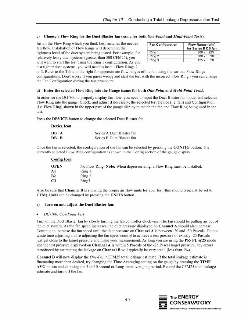
Chapter 10 Conducting a Total Leakage Depressurization Test
47 The ENERGYCONSERVATORYDIAGNOSTIC TOOLS TO MEASURE BUILDING PERFORMANCE
c) Choose a Flow Ring for the Duct Blaster fan (same for both One-Point and Multi-Point Tests).
Install the Flow Ring which you think best matches the neededfan flow. Installation of Flow Rings will depend on thetightness level of the duct system being tested. For example, forrelatively leaky duct systems (greater than 500 CFM25), youwill want to start the test using the Ring 1 configuration. As youtest tighter duct systems, you will need to install Flow Rings 2or 3. Refer to the Table to the right for approximate flow ranges of the fan using the various Flow Ringsconfigurations. Don't worry if you guess wrong and start the test with the incorrect Flow Ring - you can changethe Fan Configuration during the test procedure.
d) Enter the selected Flow Ring into the Gauge (same for both One-Point and Multi-Point Tests).
In order for the DG-700 to properly display fan flow, you need to input the Duct Blaster fan model and selectedFlow Ring into the gauge. Check, and adjust if necessary, the selected test Device (i.e. fan) and Configuration(i.e. Flow Ring) shown in the upper part of the gauge display to match the fan and Flow Ring being used in thetest.
Press the DEVICE button to change the selected Duct Blaster fan.
Device Icon
DB A Series A Duct Blaster fanDB B Series B Duct Blaster fan
Once the fan is selected, the configuration of the fan can be selected by pressing the CONFIG button. Thecurrently selected Flow Ring configuration is shown in the Config section of the gauge display.
Config Icon
OPEN No Flow Ring (Note: When depressurizing, a Flow Ring must be installed.A1 Ring 1B2 Ring 2C3 Ring3
Also be sure that Channel B is showing the proper air flow units for your test (this should typically be set toCFM). Units can be changed by pressing the UNITS button.
e) Turn on and adjust the Duct Blaster fan:
• DG-700: One-Point Test
Turn on the Duct Blaster fan by slowly turning the fan controller clockwise. The fan should be pulling air out ofthe duct system. As the fan speed increases, the duct pressure displayed on Channel A should also increase.Continue to increase the fan speed until the duct pressure on Channel A is between -20 and -30 Pascals. Do notwaste time adjusting and re-adjusting the fan speed control to achieve a test pressure of exactly -25 Pascals –just get close to the target pressure and make your measurement. As long you are using the PR/ FL @25 modeand the test pressure displayed on Channel A is within 5 Pascals of the -25 Pascal target pressure, any errorsintroduced by estimating the leakage on Channel B will typically be very small (less than 1%).
Channel B will now display the One-Point CFM25 total leakage estimate. If the total leakage estimate isfluctuating more than desired, try changing the Time Averaging setting on the gauge by pressing the TIMEAVG button and choosing the 5 or 10 second or Long-term averaging period. Record the CFM25 total leakageestimate and turn off the fan.
Fan Configuration
Flow Range (cfm)for Series B DB fan
Ring 1 800 - 225Ring 2 300 - 90Ring 3 125 - 20
Chapter 10 Conducting a Total Leakage Depressurization Test
48 The ENERGYCONSERVATORYDIAGNOSTIC TOOLS TO MEASURE BUILDING PERFORMANCE
(If “------“ or “LO” appear on Channel B, see below).
Whenever “-----” or “LO” appears on Channel B in the PR/ FL @ 25 Mode, the DG-700 can notcalculate a reliable leakage estimate. The messages “-----” and “LO” appear on Channel B under thefollowing three conditions:
- “-----” is continuously displayed when the duct test pressure from Channel A is below aminimum value of -5 Pascals. Estimating duct leakage results when the test pressure isbelow this value may result in unacceptably large errors. If possible, install a larger FlowRing to generate more fan flow.
- “LO” is continuously displayed when there is negligible air flow through the test device.
- “LO” alternates with a flow reading when the air flow reading through the device isunreliable (i.e. you are trying to measure a flow outside of the calibrated range of the testdevice in its current configuration). If possible, you should change the test deviceconfiguration to match the flow rate being measured (e.g. install a smaller Flow Ring).
Note: If you change the Flow Rings on the fan, be sure to change the Configuration setting on thegauge to match the installed Ring.
• DG-700: Multi-Point Test
Turn on the Duct Blaster fan by slowly turning the fan controller clockwise. The fan should be pulling air out ofthe duct system. As the fan speed increases, the duct pressure displayed on Channel A should also increase.Increase the fan speed until you achieve the highest target duct pressure (e.g. -35 Pascals) on Channel A. Thefan flow needed to create this duct pressure can be read directly from Channel B. Record the test readings (ductpressure and fan flow).
Now reduce the fan speed until the duct pressure equals the next target pressure (e.g. -30 Pa). Once again recordthe test readings. Continue this procedure for each of the remaining target pressures. Turn off the fan when thefinal set of readings are completed.
Enter the test readings into the TECBLAST software to generate you final CFM25 total leakage estimate. Note:Always enter a baseline pressure value of 0 into the TECBLAST Manual Data Entry Screen (because you either“zeroed out” the baseline pressure using the DG-700’s built-in baseline feature, or you skipped the optionalbaseline procedure).
(If “LO” appears on Channel B, see below).
Whenever “LO” appears on Channel B in the PR/ FL Mode, the DG-700 can not calculate a reliablefan flow reading. The message “LO” appears on Channel B under the following two conditions:
- “LO” is continuously displayed when there is negligible air flow through the test device.
- “LO” alternates with a flow reading when the air flow reading through the device isunreliable (i.e. you are trying to measure a flow outside of the calibrated range of the testdevice in its current configuration). If possible, you should change the test deviceconfiguration to match the flow rate being measured (e.g. install a smaller Flow Ring).
Note: If you change the Flow Rings on the fan, be sure to change the Configuration setting on thegauge to match the installed Ring.
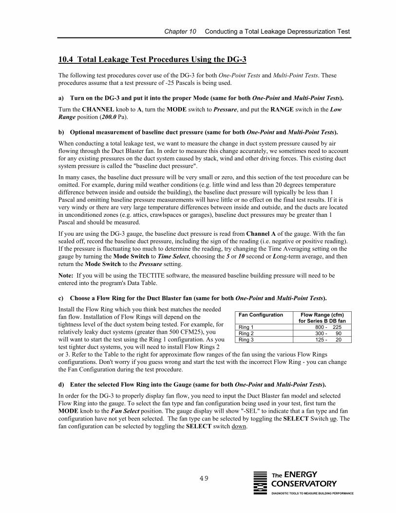
Chapter 10 Conducting a Total Leakage Depressurization Test
49
10.4 Total Leakage Test Procedures Using the DG-3
The following test procedures cover use of the DG-3 for both One-Point Tests and Multi-Point Tests. Theseprocedures assume that a test pressure of -25 Pascals is being used.
a) Turn on the DG-3 and put it into the proper Mode (same for both One-Point and Multi-Point Tests).
Turn the CHANNEL knob to A, turn the MODE switch to Pressure, and put the RANGE switch in the LowRange position (200.0 Pa).
b) Optional measurement of baseline duct pressure (same for both One-Point and Multi-Point Tests).
When conducting a total leakage test, we want to measure the change in duct system pressure caused by airflowing through the Duct Blaster fan. In order to measure this change accurately, we sometimes need to accountfor any existing pressures on the duct system caused by stack, wind and other driving forces. This existing ductsystem pressure is called the "baseline duct pressure".
In many cases, the baseline duct pressure will be very small or zero, and this section of the test procedure can beomitted. For example, during mild weather conditions (e.g. little wind and less than 20 degrees temperaturedifference between inside and outside the building), the baseline duct pressure will typically be less than 1Pascal and omitting baseline pressure measurements will have little or no effect on the final test results. If it isvery windy or there are very large temperature differences between inside and outside, and the ducts are locatedin unconditioned zones (e.g. attics, crawlspaces or garages), baseline duct pressures may be greater than 1Pascal and should be measured.
If you are using the DG-3 gauge, the baseline duct pressure is read from Channel A of the gauge. With the fansealed off, record the baseline duct pressure, including the sign of the reading (i.e. negative or positive reading).If the pressure is fluctuating too much to determine the reading, try changing the Time Averaging setting on thegauge by turning the Mode Switch to Time Select, choosing the 5 or 10 second or Long-term average, and thenreturn the Mode Switch to the Pressure setting.
Note: If you will be using the TECTITE software, the measured baseline building pressure will need to beentered into the program's Data Table.
c) Choose a Flow Ring for the Duct Blaster fan (same for both One-Point and Multi-Point Tests).
Install the Flow Ring which you think best matches the neededfan flow. Installation of Flow Rings will depend on thetightness level of the duct system being tested. For example, forrelatively leaky duct systems (greater than 500 CFM25), youwill want to start the test using the Ring 1 configuration. As youtest tighter duct systems, you will need to install Flow Rings 2or 3. Refer to the Table to the right for approximate flow ranges of thconfigurations. Don't worry if you guess wrong and start the test withthe Fan Configuration during the test procedure.
d) Enter the selected Flow Ring into the Gauge (same for both O
In order for the DG-3 to properly display fan flow, you need to inputFlow Ring into the gauge. To select the fan type and fan configuratioMODE knob to the Fan Select position. The gauge display will showconfiguration have not yet been selected. The fan type can be selectefan configuration can be selected by toggling the SELECT switch do
Fan Configuration
Flow Range (cfm)for Series B DB fan
Ring 1 800 - 225Ring 2 300 - 90Ring 3 125 - 20
The ENERGYCONSERVATORYDIAGNOSTIC TOOLS TO MEASURE BUILDING PERFORMANCE
e fan using the various Flow Rings the incorrect Flow Ring - you can change
ne-Point and Multi-Point Tests).
the Duct Blaster fan model and selectedn being used in your test, first turn the "-SEL" to indicate that a fan type and fand by toggling the SELECT Switch up. Thewn.
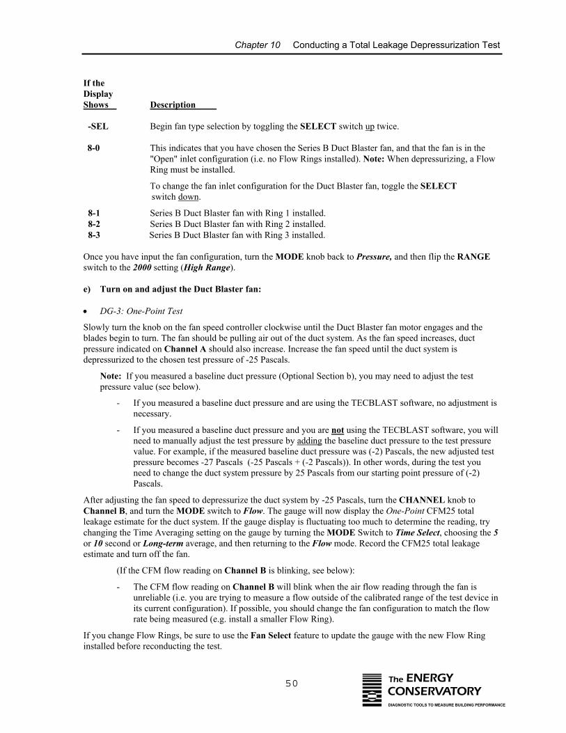
Chapter 10 Conducting a Total Leakage Depressurization Test
50 The ENERGYCONSERVATORYDIAGNOSTIC TOOLS TO MEASURE BUILDING PERFORMANCE
If the DisplayShows Description
-SEL Begin fan type selection by toggling the SELECT switch up twice.
8-0 This indicates that you have chosen the Series B Duct Blaster fan, and that the fan is in the"Open" inlet configuration (i.e. no Flow Rings installed). Note: When depressurizing, a FlowRing must be installed.
To change the fan inlet configuration for the Duct Blaster fan, toggle the SELECT switch down.
8-1 Series B Duct Blaster fan with Ring 1 installed. 8-2 Series B Duct Blaster fan with Ring 2 installed. 8-3 Series B Duct Blaster fan with Ring 3 installed.
Once you have input the fan configuration, turn the MODE knob back to Pressure, and then flip the RANGEswitch to the 2000 setting (High Range).
e) Turn on and adjust the Duct Blaster fan:
• DG-3: One-Point Test
Slowly turn the knob on the fan speed controller clockwise until the Duct Blaster fan motor engages and theblades begin to turn. The fan should be pulling air out of the duct system. As the fan speed increases, ductpressure indicated on Channel A should also increase. Increase the fan speed until the duct system isdepressurized to the chosen test pressure of -25 Pascals.
Note: If you measured a baseline duct pressure (Optional Section b), you may need to adjust the testpressure value (see below).
- If you measured a baseline duct pressure and are using the TECBLAST software, no adjustment isnecessary.
- If you measured a baseline duct pressure and you are not using the TECBLAST software, you willneed to manually adjust the test pressure by adding the baseline duct pressure to the test pressurevalue. For example, if the measured baseline duct pressure was (-2) Pascals, the new adjusted testpressure becomes -27 Pascals (-25 Pascals + (-2 Pascals)). In other words, during the test youneed to change the duct system pressure by 25 Pascals from our starting point pressure of (-2)Pascals.
After adjusting the fan speed to depressurize the duct system by -25 Pascals, turn the CHANNEL knob toChannel B, and turn the MODE switch to Flow. The gauge will now display the One-Point CFM25 totalleakage estimate for the duct system. If the gauge display is fluctuating too much to determine the reading, trychanging the Time Averaging setting on the gauge by turning the MODE Switch to Time Select, choosing the 5or 10 second or Long-term average, and then returning to the Flow mode. Record the CFM25 total leakageestimate and turn off the fan.
(If the CFM flow reading on Channel B is blinking, see below):
- The CFM flow reading on Channel B will blink when the air flow reading through the fan isunreliable (i.e. you are trying to measure a flow outside of the calibrated range of the test device inits current configuration). If possible, you should change the fan configuration to match the flowrate being measured (e.g. install a smaller Flow Ring).
If you change Flow Rings, be sure to use the Fan Select feature to update the gauge with the new Flow Ringinstalled before reconducting the test.

Chapter 10 Conducting a Total Leakage Depressurization Test
51 The ENERGYCONSERVATORYDIAGNOSTIC TOOLS TO MEASURE BUILDING PERFORMANCE
• DG-3: Multi-Point Test
Slowly turn the knob on the fan speed controller clockwise until the Duct Blaster fan motor engages and theblades begin to turn. The fan should be pulling air out of the duct system. As the fan speed increases, ductpressure indicated on Channel A should also increase. Increase the fan speed until you achieve the highesttarget duct pressure (e.g. -35 Pascals) on Channel A. Now determine the air flow through the fan needed tocreate this duct pressure by first turning the CHANNEL switch to Channel B, and then turning the MODEknob to the Flow position. The gauge will now display the flow through the fan. Record the test readings (ductpressure and fan flow).
Turn the CHANNEL switch back to Channel A and then turn the MODE knob back to the Pressure setting.Now reduce the fan speed until the duct pressure equals the next target pressure (e.g. -30 Pa). Once againdetermine the air flow from Channel B and record the test readings. Continue this procedure for each of theremaining target pressures. Turn off the fan when the final set of readings are completed.
Enter the test readings into the TECBLAST software to generate your final CFM25 total leakage estimate.
(If the CFM flow reading on Channel B is blinking, see below):
- The CFM flow reading on Channel B will blink when the air flow reading through the fan isunreliable (i.e. you are trying to measure a flow outside of the calibrated range of the test device inits current configuration). If possible, you should change the fan configuration to match the flowrate being measured (e.g. install a smaller Flow Ring).
- If you change Flow Rings, be sure to use the Fan Select feature to update the gauge with the newFlow Ring installed before reconducting the test.
10.5 Using the Can’t Reach Pressure Factors (One-Point Tests)
If you were performing a One-Point Test and the Duct Blaster fan was unable to depressurize the duct system by-25 Pascals because one of the smallest Flow Rings was installed (e.g. Ring 2 or 3), replace the Flow Ring witha larger Flow Ring (e.g. Ring 1) to increase the maximum air flow available from the fan. If you were not ableto depressurize the duct system by –25 Pascals because the duct system is extremely leaky, use the followinginstructions:
• For DG-700 Users: No adjustments to the test procedure above are necessary other than to make sure the gauge was in the PR/ FL @25 mode during the One-Point Test. If you can not achieve the target test pressure of approximately -25 Pascals because the duct system is extremely leaky, a CFM25 total leakage estimate will automatically bedisplayed on Channel B. The leakage estimate shown on Channel B is determined by continuously adjustingthe measured air flow from the Duct Blaster fan to a test pressure of -25 Pascals, using the real-time Channel Aduct pressure reading and the Can’t Reach Pressure Factors shown in Table 6 below.
• For DG-3 Users:
Take your One-Point Test reading at the highest achievable duct pressure. Now manually use Table 6 below toestimate the amount of air flow through the Duct Blaster fan it would take to reach the target pressure. To useTable 6, determine the flow required to maintain the highest achievable duct pressure listed in the Table.Multiply this flow by the corresponding "Can't Reach Pressure (CRP) Factor" to estimate flow that would berequired to maintain a -25 Pascal duct pressure.
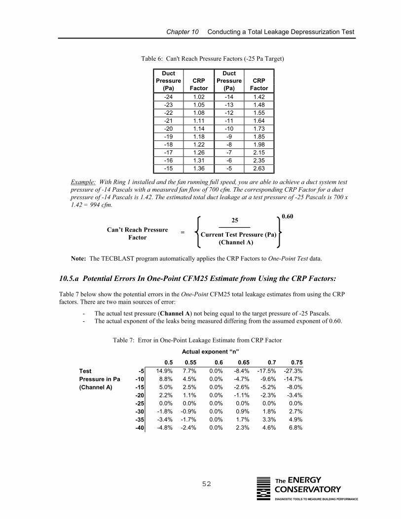
Chapter 10 Conducting a Total Leakage Depressurization Test
Table 6: Can't Reach Pressure Factors (-25 Pa Target)
Example: With Ring 1 installed apressure of -14 Pascals with a mepressure of -14 Pascals is 1.42. T1.42 = 994 cfm.
Note: The TECBLAST program
10.5.a Potential Errors In One
Table 7 below show the potential errofactors. There are two main sources of
- The actual test pressure (- The actual exponent of t
Can’t Reach PressFactor
P
Test -5 1Pressure in Pa -10(Channel A) -15
-20-25-30 --35 --40 -
Table 7: Error in
Duct Ductressure CRP Pressure CRP(Pa) Factor (Pa) Factor-24 1.02 -14 1.42-23 1.05 -13 1.48-22 1.08 -12 1.55-21 1.11 -11 1.64-20 1.14 -10 1.73-19 1.18 -9 1.85-18 1.22 -8 1.98-17 1.26 -7 2.15-16 1.31 -6 2.35-15 1.36 -5 2.63
52 The ENERGYCONSERVATORYDIAGNOSTIC TOOLS TO MEASURE BUILDING PERFORMANCE
nd the fan running full speed, you are able to achieve a duct system testasured fan flow of 700 cfm. The corresponding CRP Factor for a ducthe estimated total duct leakage at a test pressure of -25 Pascals is 700 x
automatically applies the CRP Factors to One-Point Test data.
-Point CFM25 Estimate from Using the CRP Factors:
rs in the One-Point CFM25 total leakage estimates from using the CRP error:
Channel A) not being equal to the target pressure of -25 Pascals. he leaks being measured differing from the assumed exponent of 0.60.
25
Current Test Pressure (Pa) (Channel A)
0.60
ure =
Actual exponent “n”
0.54.9%
0.55 0.6 0.657.7% 0.0% -8.4%
0.7-17.5%
0.75-27.3%
8.8% 4.5% 0.0% -4.7% -9.6% -14.7%5.0% 2.5% 0.0% -2.6% -5.2% -8.0%2.2% 1.1% 0.0% -1.1% -2.3% -3.4%0.0% 0.0% 0.0% 0.0% 0.0% 0.0%1.8% -0.9% 0.0% 0.9% 1.8% 2.7%3.4% -1.7% 0.0% 1.7% 3.3% 4.9%4.8% -2.4% 0.0% 2.3% 4.6% 6.8%
One-Point Leakage Estimate from CRP Factor
Chapter 10 Conducting a Total Leakage Depressurization Test
53 The ENERGYCONSERVATORYDIAGNOSTIC TOOLS TO MEASURE BUILDING PERFORMANCE
For example, Table 7 shows that for a One-Point 25 Pa duct airtightness test, a 4.5% error would be introducedif the leakage estimate was determined at an actual test pressure of -10 Pa (Channel A), and the actual exponentof the leaks was 0.55 rather than the assumed value of 0.60.
10.6 Unable to Reach a Target Building Pressure During a Multi-Point Test?
If the Duct Blaster fan was unable to achieve the highest target duct pressure (e.g. -35 Pascals) because one ofthe smallest Flow Rings was installed (e.g. Ring 2 or Ring 3), replace the Flow Ring with a Larger Flow Ring(e.g. Ring 1) and repeat the test. If you were not able to reach the highest target pressure because the ductsystem is extremely leaky, take your first set of test readings the highest achievable duct pressure. Continueyour test by using the remaining target pressures which are less than the highest achievable pressure. Enter thesetest values into the TECBLAST program to generate your total leakage estimate.
10.7 Before Leaving the Building
Be sure you have returned the building to its original condition before leaving. This includes removing anytemporary register seals, turning HVAC controls to their original settings and closing access doors or ventsopened during the test. In addition, it is highly recommended that the test procedures outlined in Chapters 14and 15 be performed before leaving the building.
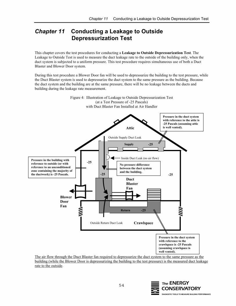
Chapter 11 Conducting a Leakage to Outside Depressurization Test
54 The ENERGYCONSERVATORYDIAGNOSTIC TOOLS TO MEASURE BUILDING PERFORMANCE
Chapter 11 Conducting a Leakage to Outside Depressurization Test
This chapter covers the test procedures for conducting a Leakage to Outside Depressurization Test. TheLeakage to Outside Test is used to measure the duct leakage rate to the outside of the building only, when theduct system is subjected to a uniform pressure. This test procedure requires simultaneous use of both a DuctBlaster and Blower Door system.
During this test procedure a Blower Door fan will be used to depressurize the building to the test pressure, whilethe Duct Blaster system is used to depressurize the duct system to the same pressure as the building. Becausethe duct system and the building are at the same pressure, there will be no leakage between the ducts andbuilding during the leakage rate measurement.
Figure 4: Illustration of Leakage to Outside Depressurization Test(at a Test Pressure of -25 Pascals)
with Duct Blaster Fan Installed at Air Handler
Outside Supply Duct Leak
Supply
Return
-25
-25
DuctBlasterFan
BlowerDoorFan
Inside Duct Leak (no air flow)
Outside Return Duct Leak Crawlspace
Attic
-25
Pressure in the duct systemwith reference to the attic is-25 Pascals (assuming atticis well vented).
Pressure in the duct systemwith reference to thecrawlspace is -25 Pascals(assuming crawlspace iswell vented).
Pressure in the building withreference to outside (or withreference to an unconditionedzone containing the majority ofthe ductwork) is -25 Pascals.
-25
-25
No pressure differencebetween the duct systemand the building.
The air flow through the Duct Blaster fan required to depressurize the duct system to the same pressure as thebuilding (while the Blower Door is depressurizing the building to the test pressure) is the measured duct leakagerate to the outside.
Chapter 11 Conducting a Leakage to Outside Depressurization Test
55 The ENERGYCONSERVATORYDIAGNOSTIC TOOLS TO MEASURE BUILDING PERFORMANCE
The following instructions assume you have set up the Duct Blaster system for a depressurization test asoutlined in Chapter 9 above. Information on how to conduct a Leakage to Outside Pressurization Test (i.e.blowing air into the duct system ) is discussed in Chapter 7.
Note: It is possible to separately measure supply and return duct leaks by installing a temporary barrier in eitherthe supply or return opening to the air handler cabinet. With a temporary barrier in place, each side of the ductsystem can be tested independently. It is also possible to separately measure supply and return leakage beforethe air handler or furnace unit have been installed.
11.1 Final Preparations (Set Up Blower Door in Building)
Install the Blower Door system in a centrally located exterior door, including a gauge to measure buildingpressure. You will need to prepare the building for a Blower Door test as described in the Blower DoorOperation Manual including closing all exterior doors and windows, opening all interior doors, and adjustingcombustion appliances to remain off during the test. The Blower Door fan should be set up to depressurize (orblow air out of) the building. Importantly, we will not be measuring air flow through the Blower Door fanduring this test procedure. This means that the Blower Door system can either be set up in the standarddepressurization test mode, or it can be set up in the pressurization test mode, with the fan direction switchreversed to blow air out of the building. Refer to your Blower Door manual for complete instructions on BlowerDoor system installation.
11.1.a Building Pressure Measurements:
During the test, you will need to monitor the change in building pressure caused by the Blower Door system.Typically the Blower Door building pressure gauge will be setup to measure building pressure with reference tothe outside (this is the typical set up for a Blower Door test).
However, if you are testing a duct system that is located primarily in one unconditioned zone (e.g. a single atticor single crawlspace), you have the option of setting up the gauge to measure building pressure with reference tothat zone, rather than with reference to outside. The purpose of making this change is to ensure that the ductleaks located in that zone are subjected to the full test pressure.
For example, it is possible that a crawlspace containing most of the ductwork may be significantly depressurizedby air being pulled out of that zone from the Blower Door fan (through air leaks between the building and thecrawlspace). In this case, you may underestimate the duct leakage rate if you are measuring building pressurewith respect to outside during your test because the leaks in the crawlspace ductwork will not be subjected to thefull test pressure (i.e. they will be subjected to the test pressure minus the crawlspace depressurization caused bythe Blower Door fan). Changing the reference tap on the Blower Door building pressure gauge from outside tothe crawlspace would eliminate the underestimation problem in this building.
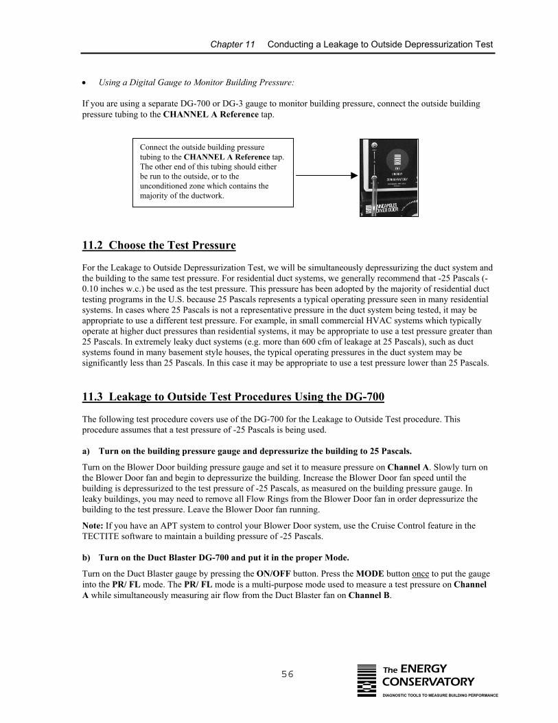
Chapter 11 Conducting a Leakage to Outside Depressurization Test
56 The ENERGYCONSERVATORYDIAGNOSTIC TOOLS TO MEASURE BUILDING PERFORMANCE
• Using a Digital Gauge to Monitor Building Pressure:
If you are using a separate DG-700 or DG-3 gauge to monitor building pressure, connect the outside buildingpressure tubing to the CHANNEL A Reference tap.
a)
b)
Connect the outside building pressuretubing to the CHANNEL A Reference tap.The other end of this tubing should eitherbe run to the outside, or to theunconditioned zone which contains themajority of the ductwork.
11.2 Choose the Test Pressure
For the Leakage to Outside Depressurization Test, we will be simultaneously depressurizing the duct system andthe building to the same test pressure. For residential duct systems, we generally recommend that -25 Pascals (-0.10 inches w.c.) be used as the test pressure. This pressure has been adopted by the majority of residential ducttesting programs in the U.S. because 25 Pascals represents a typical operating pressure seen in many residentialsystems. In cases where 25 Pascals is not a representative pressure in the duct system being tested, it may beappropriate to use a different test pressure. For example, in small commercial HVAC systems which typicallyoperate at higher duct pressures than residential systems, it may be appropriate to use a test pressure greater than25 Pascals. In extremely leaky duct systems (e.g. more than 600 cfm of leakage at 25 Pascals), such as ductsystems found in many basement style houses, the typical operating pressures in the duct system may besignificantly less than 25 Pascals. In this case it may be appropriate to use a test pressure lower than 25 Pascals.
11.3 Leakage to Outside Test Procedures Using the DG-700
The following test procedure covers use of the DG-700 for the Leakage to Outside Test procedure. Thisprocedure assumes that a test pressure of -25 Pascals is being used.
Turn on the building pressure gauge and depressurize the building to 25 Pascals.
Turn on the Blower Door building pressure gauge and set it to measure pressure on Channel A. Slowly turn onthe Blower Door fan and begin to depressurize the building. Increase the Blower Door fan speed until thebuilding is depressurized to the test pressure of -25 Pascals, as measured on the building pressure gauge. Inleaky buildings, you may need to remove all Flow Rings from the Blower Door fan in order depressurize thebuilding to the test pressure. Leave the Blower Door fan running.
Note: If you have an APT system to control your Blower Door system, use the Cruise Control feature in theTECTITE software to maintain a building pressure of -25 Pascals.
Turn on the Duct Blaster DG-700 and put it in the proper Mode.
Turn on the Duct Blaster gauge by pressing the ON/OFF button. Press the MODE button once to put the gaugeinto the PR/ FL mode. The PR/ FL mode is a multi-purpose mode used to measure a test pressure on ChannelA while simultaneously measuring air flow from the Duct Blaster fan on Channel B.
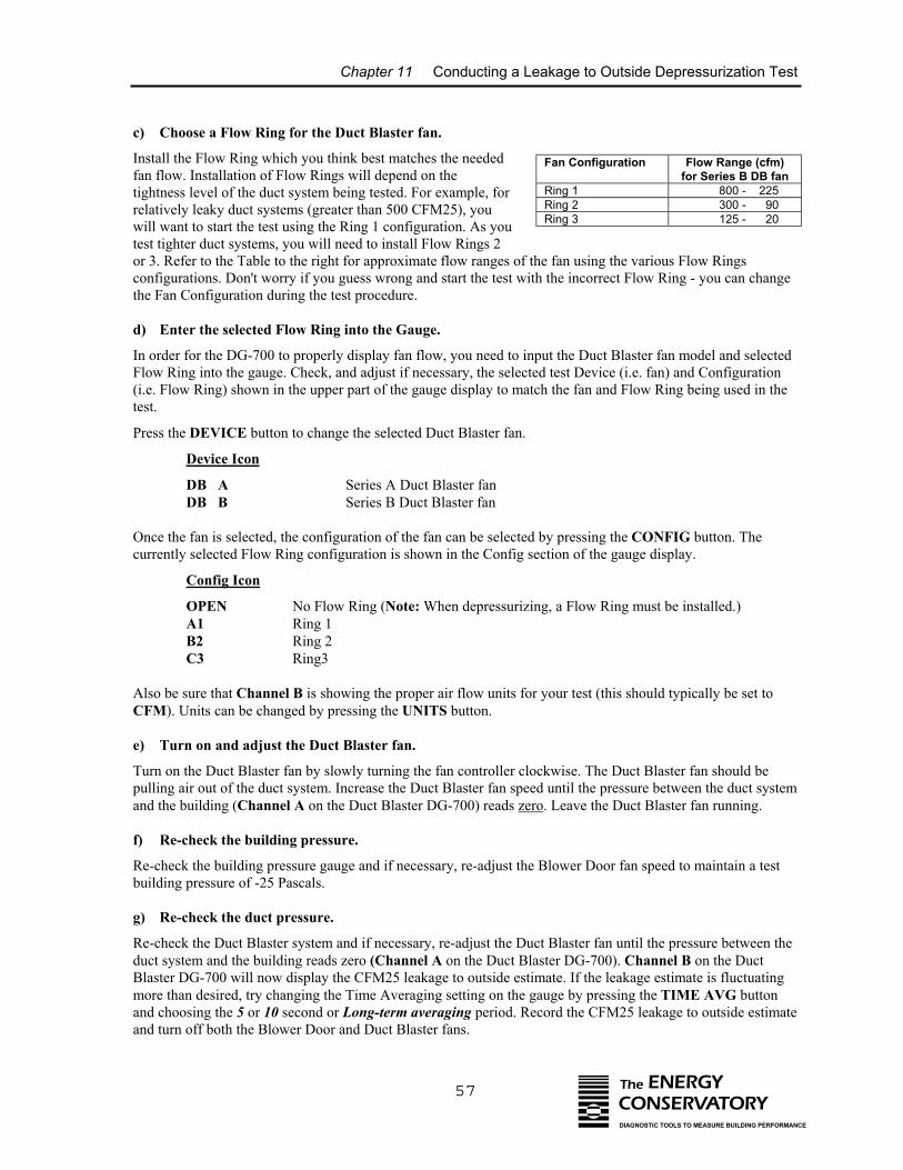
Chapter 11 Conducting a Leakage to Outside Depressurization Test
57 The ENERGYCONSERVATORYDIAGNOSTIC TOOLS TO MEASURE BUILDING PERFORMANCE
c) Choose a Flow Ring for the Duct Blaster fan.
Install the Flow Ring which you think best matches the neededfan flow. Installation of Flow Rings will depend on thetightness level of the duct system being tested. For example, forrelatively leaky duct systems (greater than 500 CFM25), youwill want to start the test using the Ring 1 configuration. As youtest tighter duct systems, you will need to install Flow Rings 2or 3. Refer to the Table to the right for approximate flow ranges of the fan using the various Flow Ringsconfigurations. Don't worry if you guess wrong and start the test with the incorrect Flow Ring - you can changethe Fan Configuration during the test procedure.
d) Enter the selected Flow Ring into the Gauge.
In order for the DG-700 to properly display fan flow, you need to input the Duct Blaster fan model and selectedFlow Ring into the gauge. Check, and adjust if necessary, the selected test Device (i.e. fan) and Configuration(i.e. Flow Ring) shown in the upper part of the gauge display to match the fan and Flow Ring being used in thetest.
Press the DEVICE button to change the selected Duct Blaster fan.
Device Icon
DB A Series A Duct Blaster fanDB B Series B Duct Blaster fan
Once the fan is selected, the configuration of the fan can be selected by pressing the CONFIG button. Thecurrently selected Flow Ring configuration is shown in the Config section of the gauge display.
Config Icon
OPEN No Flow Ring (Note: When depressurizing, a Flow Ring must be installed.)A1 Ring 1B2 Ring 2C3 Ring3
Also be sure that Channel B is showing the proper air flow units for your test (this should typically be set toCFM). Units can be changed by pressing the UNITS button.
e) Turn on and adjust the Duct Blaster fan.
Turn on the Duct Blaster fan by slowly turning the fan controller clockwise. The Duct Blaster fan should bepulling air out of the duct system. Increase the Duct Blaster fan speed until the pressure between the duct systemand the building (Channel A on the Duct Blaster DG-700) reads zero. Leave the Duct Blaster fan running.
f) Re-check the building pressure.
Re-check the building pressure gauge and if necessary, re-adjust the Blower Door fan speed to maintain a testbuilding pressure of -25 Pascals.
g) Re-check the duct pressure.
Re-check the Duct Blaster system and if necessary, re-adjust the Duct Blaster fan until the pressure between theduct system and the building reads zero (Channel A on the Duct Blaster DG-700). Channel B on the DuctBlaster DG-700 will now display the CFM25 leakage to outside estimate. If the leakage estimate is fluctuatingmore than desired, try changing the Time Averaging setting on the gauge by pressing the TIME AVG buttonand choosing the 5 or 10 second or Long-term averaging period. Record the CFM25 leakage to outside estimateand turn off both the Blower Door and Duct Blaster fans.
Fan Configuration
Flow Range (cfm)for Series B DB fan
Ring 1 800 - 225Ring 2 300 - 90Ring 3 125 - 20
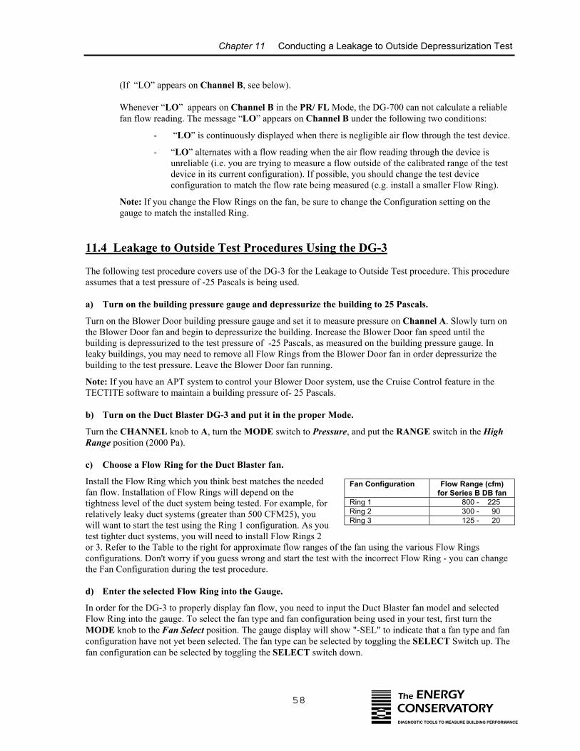
Chapter 11 Conducting a Leakage to Outside Depressurization Test
58 The ENERGYCONSERVATORYDIAGNOSTIC TOOLS TO MEASURE BUILDING PERFORMANCE
(If “LO” appears on Channel B, see below).
Whenever “LO” appears on Channel B in the PR/ FL Mode, the DG-700 can not calculate a reliablefan flow reading. The message “LO” appears on Channel B under the following two conditions:
- “LO” is continuously displayed when there is negligible air flow through the test device.
- “LO” alternates with a flow reading when the air flow reading through the device isunreliable (i.e. you are trying to measure a flow outside of the calibrated range of the testdevice in its current configuration). If possible, you should change the test deviceconfiguration to match the flow rate being measured (e.g. install a smaller Flow Ring).
Note: If you change the Flow Rings on the fan, be sure to change the Configuration setting on thegauge to match the installed Ring.
11.4 Leakage to Outside Test Procedures Using the DG-3
The following test procedure covers use of the DG-3 for the Leakage to Outside Test procedure. This procedureassumes that a test pressure of -25 Pascals is being used.
a) Turn on the building pressure gauge and depressurize the building to 25 Pascals.
Turn on the Blower Door building pressure gauge and set it to measure pressure on Channel A. Slowly turn onthe Blower Door fan and begin to depressurize the building. Increase the Blower Door fan speed until thebuilding is depressurized to the test pressure of -25 Pascals, as measured on the building pressure gauge. Inleaky buildings, you may need to remove all Flow Rings from the Blower Door fan in order depressurize thebuilding to the test pressure. Leave the Blower Door fan running.
Note: If you have an APT system to control your Blower Door system, use the Cruise Control feature in theTECTITE software to maintain a building pressure of- 25 Pascals.
b) Turn on the Duct Blaster DG-3 and put it in the proper Mode.
Turn the CHANNEL knob to A, turn the MODE switch to Pressure, and put the RANGE switch in the HighRange position (2000 Pa).
c) Choose a Flow Ring for the Duct Blaster fan.
Install the Flow Ring which you think best matches the neededfan flow. Installation of Flow Rings will depend on thetightness level of the duct system being tested. For example, forrelatively leaky duct systems (greater than 500 CFM25), youwill want to start the test using the Ring 1 configuration. As youtest tighter duct systems, you will need to install Flow Rings 2or 3. Refer to the Table to the right for approximate flow ranges of the fan using the various Flow Ringsconfigurations. Don't worry if you guess wrong and start the test with the incorrect Flow Ring - you can changethe Fan Configuration during the test procedure.
d) Enter the selected Flow Ring into the Gauge.
In order for the DG-3 to properly display fan flow, you need to input the Duct Blaster fan model and selectedFlow Ring into the gauge. To select the fan type and fan configuration being used in your test, first turn theMODE knob to the Fan Select position. The gauge display will show "-SEL" to indicate that a fan type and fanconfiguration have not yet been selected. The fan type can be selected by toggling the SELECT Switch up. Thefan configuration can be selected by toggling the SELECT switch down.
Fan Configuration
Flow Range (cfm)for Series B DB fan
Ring 1 800 - 225Ring 2 300 - 90Ring 3 125 - 20
Chapter 11 Conducting a Leakage to Outside Depressurization Test
59 The ENERGYCONSERVATORYDIAGNOSTIC TOOLS TO MEASURE BUILDING PERFORMANCE
If the DisplayShows Description
-SEL Begin fan type selection by toggling the SELECT switch up twice.
8-0 This indicates that you have chosen the Series B Duct Blaster fan, and that the fan is in the"Open" inlet configuration (i.e. no Flow Rings installed). Note: When depressurizing, a FlowRing must be installed.
To change the fan inlet configuration for the Duct Blaster fan, toggle the SELECT switch down.
8-1 Series B Duct Blaster fan with Ring 1 installed. 8-2 Series B Duct Blaster fan with Ring 2 installed. 8-3 Series B Duct Blaster fan with Ring 3 installed.
e) Turn on and adjust the Duct Blaster fan.
Turn on the Duct Blaster fan by slowly turning the fan controller clockwise. The Duct Blaster fan should bepulling air out of the duct system. Increase the Duct Blaster fan speed until the pressure between the duct systemand the building (Channel A on the Duct Blaster DG-3) reads zero. Leave the Duct Blaster fan running.
f) Re-check the building pressure.
Re-check the building pressure gauge and if necessary, re-adjust the Blower Door fan speed to maintain a testbuilding pressure of -25 Pascals.
g) Re-check the duct pressure.
Re-check the Duct Blaster system and if necessary, re-adjust the Duct Blaster fan until the pressure between theduct system and the building reads zero (Channel A on the Duct Blaster DG-3). After re-adjusting the fanspeed, turn the CHANNEL knob to Channel B, and turn the MODE switch to Flow. The gauge will nowdisplay the CFM25 leakage to outside estimate. If the gauge display is fluctuating too much to determine thereading, try changing the Time Averaging setting on the gauge by turning the MODE Switch to Time Select,choosing the 5 or 10 second or Long-term average, and then returning to the Flow mode. Record the CFM25leakage to outside estimate and turn off both the Blower Door and Duct Blaster fans.
(If the CFM flow reading on Channel B is blinking, see below):
- The CFM flow reading on Channel B will blink when the air flow reading through the fan isunreliable (i.e. you are trying to measure a flow outside of the calibrated range of the test device inits current configuration). If possible, you should change the fan configuration to match the flowrate being measured (e.g. install a smaller Flow Ring).
- If you change Flow Rings, be sure to use the Fan Select feature to update the gauge with the newFlow Ring installed before reconducting the test.
11.5 What If You Can Not Depressurize the Building to the Test Pressure withthe Blower Door Fan?
If the Blower Door system is unable to depressurize the building to the test pressure because one of the FlowRings was installed on the Blower Door fan, remove the Flow Ring and repeat the test. If you are not able todepressurize the building to the test pressure because the building is too leaky, then you will need to conduct thetest at the highest achievable building pressure and use the Can't Reach Pressure Factors below to estimate thefinal duct leakage rate.
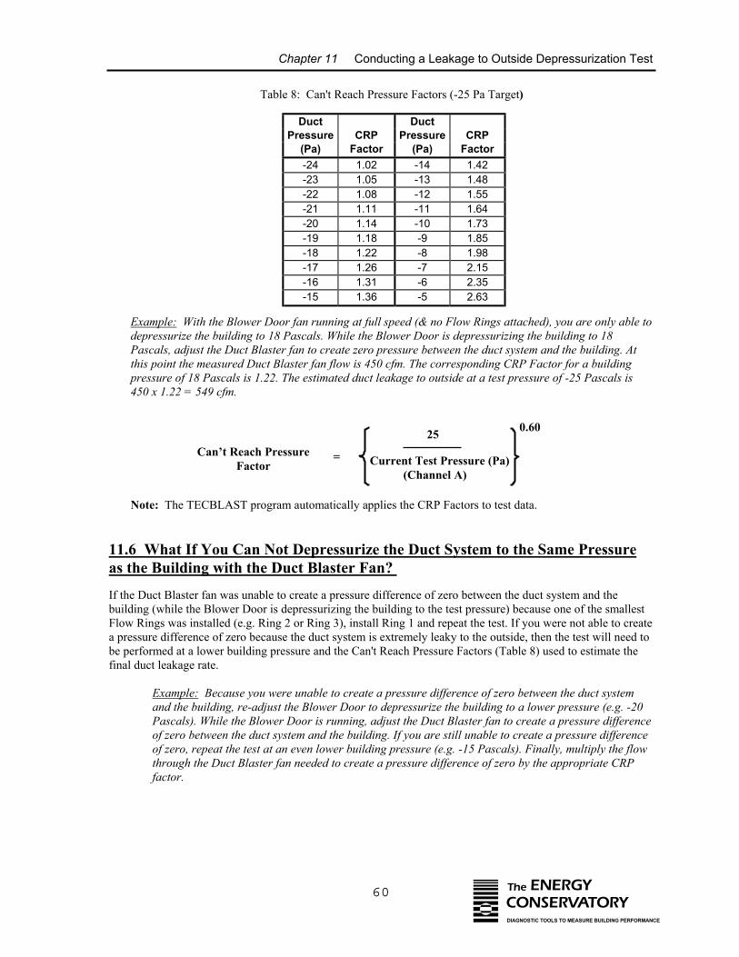
Chapter 11 Conducting a Leakage to Outside Depressurization Test
Table 8: Can't Reach Pressure Factors (-25 Pa Target)
P
Example: With the Blower Door depressurize the building to 18 PaPascals, adjust the Duct Blaster fthis point the measured Duct Blaspressure of 18 Pascals is 1.22. Th450 x 1.22 = 549 cfm.
Note: The TECBLAST program
Can’t Reach PressFactor
11.6 What If You Can Not as the Building with the Duc
If the Duct Blaster fan was unable to cbuilding (while the Blower Door is deFlow Rings was installed (e.g. Ring 2 a pressure difference of zero because tbe performed at a lower building pressfinal duct leakage rate.
Example: Because you wereand the building, re-adjust thPascals). While the Blower Dof zero between the duct systeof zero, repeat the test at an ethrough the Duct Blaster fan factor.
Duct Ductressure CRP Pressure CRP(Pa) Factor (Pa) Factor-24 1.02 -14 1.42-23 1.05 -13 1.48-22 1.08 -12 1.55-21 1.11 -11 1.64-20 1.14 -10 1.73-19 1.18 -9 1.85-18 1.22 -8 1.98-17 1.26 -7 2.15-16 1.31 -6 2.35-15 1.36 -5 2.63
60 The ENERGYCONSERVATORYDIAGNOSTIC TOOLS TO MEASURE BUILDING PERFORMANCE
25
Current Test Pressure (Pa) (Channel A)
fan running at full speed (& no Flow Rings attached), you are only able toscals. While the Blower Door is depressurizing the building to 18
an to create zero pressure between the duct system and the building. Atter fan flow is 450 cfm. The corresponding CRP Factor for a buildinge estimated duct leakage to outside at a test pressure of -25 Pascals is
automatically applies the CRP Factors to test data.
0.60
ure =
Depressurize the Duct System to the Same Pressuret Blaster Fan?
reate a pressure difference of zero between the duct system and thepressurizing the building to the test pressure) because one of the smallestor Ring 3), install Ring 1 and repeat the test. If you were not able to createhe duct system is extremely leaky to the outside, then the test will need toure and the Can't Reach Pressure Factors (Table 8) used to estimate the
unable to create a pressure difference of zero between the duct systeme Blower Door to depressurize the building to a lower pressure (e.g. -20oor is running, adjust the Duct Blaster fan to create a pressure differencem and the building. If you are still unable to create a pressure differenceven lower building pressure (e.g. -15 Pascals). Finally, multiply the flowneeded to create a pressure difference of zero by the appropriate CRP
Chapter 11 Conducting a Leakage to Outside Depressurization Test
61 The ENERGYCONSERVATORYDIAGNOSTIC TOOLS TO MEASURE BUILDING PERFORMANCE
For example, with the Blower Door depressurizing the building to -15 Pascals, the flow through theDuct Blaster fan needed to create a pressure difference of zero (between the duct system and thebuilding) is 600 cfm. The corresponding CRP Factor for a building pressure of -15 Pascals is 1.36.The estimated duct leakage to outside at a test pressure of -25 Pascals is 600 x 1.36 = 816 cfm.
Note: The TECBLAST program will automatically apply the CRP Factors to test data.
11.7 Before Leaving the Building
Be sure you have returned the building to its original condition before leaving. This includes removing anytemporary register seals, turning HVAC controls to their original settings and closing access doors or ventsopened during the test. In addition, it is highly recommended that the test procedures outlined in Chapters 14and 15 be performed before leaving the building.
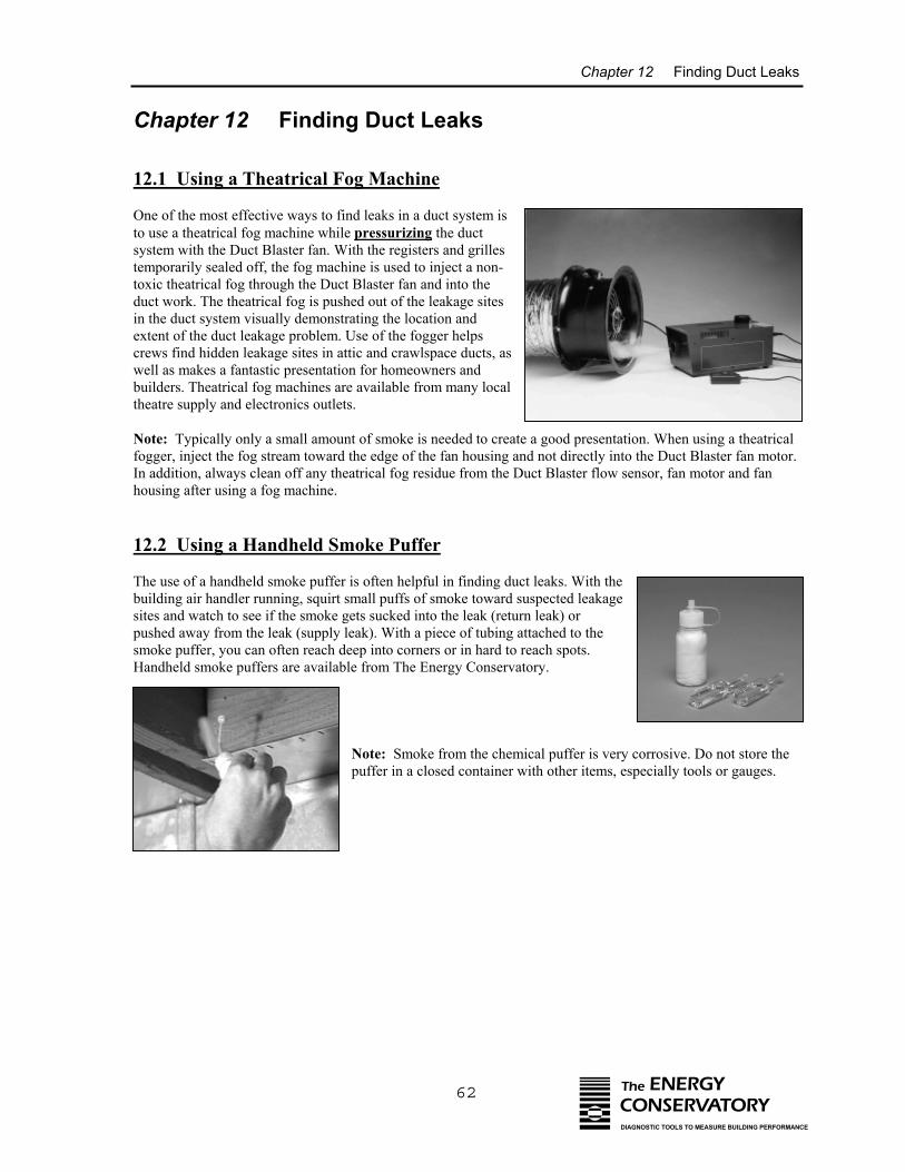
Chapter 12 Finding Duct Leaks
62 The ENERGYCONSERVATORYDIAGNOSTIC TOOLS TO MEASURE BUILDING PERFORMANCE
Chapter 12 Finding Duct Leaks
12.1 Using a Theatrical Fog Machine
One of the most effective ways to find leaks in a duct system isto use a theatrical fog machine while pressurizing the ductsystem with the Duct Blaster fan. With the registers and grillestemporarily sealed off, the fog machine is used to inject a non-toxic theatrical fog through the Duct Blaster fan and into theduct work. The theatrical fog is pushed out of the leakage sitesin the duct system visually demonstrating the location andextent of the duct leakage problem. Use of the fogger helpscrews find hidden leakage sites in attic and crawlspace ducts, aswell as makes a fantastic presentation for homeowners andbuilders. Theatrical fog machines are available from many localtheatre supply and electronics outlets.
Note: Typically only a small amount of smoke is needed to create a good presentation. When using a theatricalfogger, inject the fog stream toward the edge of the fan housing and not directly into the Duct Blaster fan motor.In addition, always clean off any theatrical fog residue from the Duct Blaster flow sensor, fan motor and fanhousing after using a fog machine.
12.2 Using a Handheld Smoke Puffer
The use of a handheld smoke puffer is often helpful in finding duct leaks. With thebuilding air handler running, squirt small puffs of smoke toward suspected leakagesites and watch to see if the smoke gets sucked into the leak (return leak) orpushed away from the leak (supply leak). With a piece of tubing attached to thesmoke puffer, you can often reach deep into corners or in hard to reach spots.Handheld smoke puffers are available from The Energy Conservatory.
Note: Smoke from the chemical puffer is very corrosive. Do not store thepuffer in a closed container with other items, especially tools or gauges.
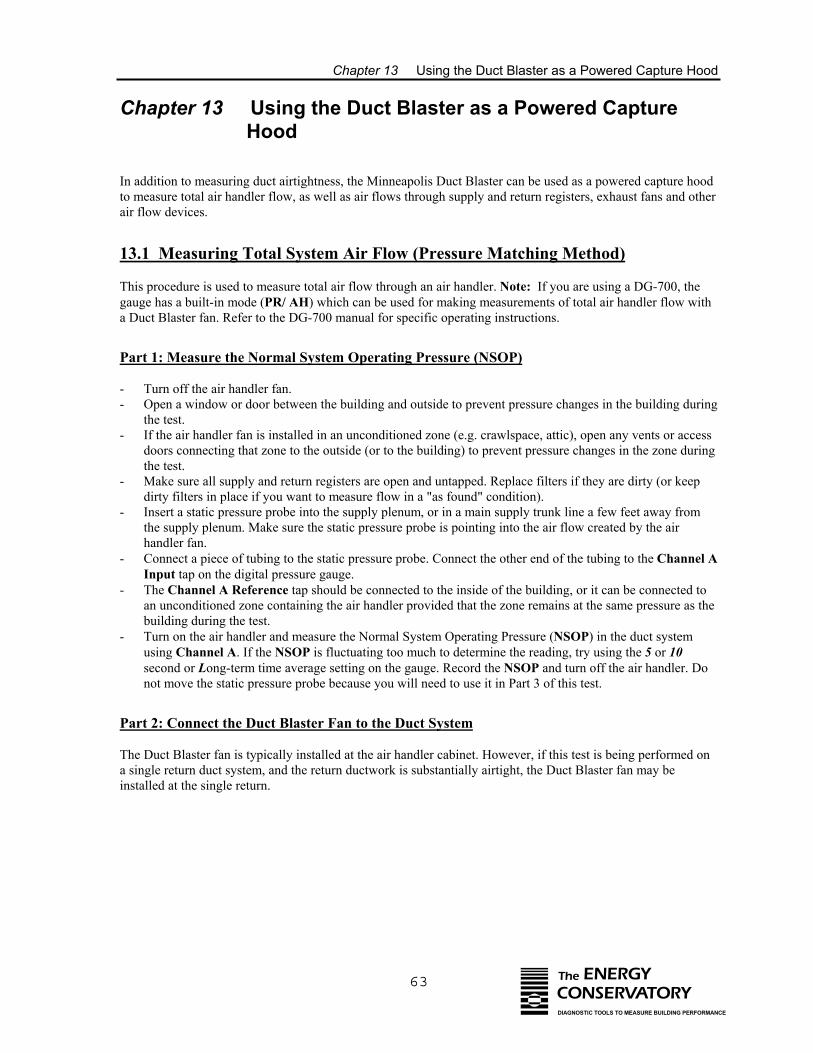
Chapter 13 Using the Duct Blaster as a Powered Capture Hood
63 The ENERGYCONSERVATORYDIAGNOSTIC TOOLS TO MEASURE BUILDING PERFORMANCE
Chapter 13 Using the Duct Blaster as a Powered Capture Hood
In addition to measuring duct airtightness, the Minneapolis Duct Blaster can be used as a powered capture hoodto measure total air handler flow, as well as air flows through supply and return registers, exhaust fans and otherair flow devices.
13.1 Measuring Total System Air Flow (Pressure Matching Method)
This procedure is used to measure total air flow through an air handler. Note: If you are using a DG-700, thegauge has a built-in mode (PR/ AH) which can be used for making measurements of total air handler flow witha Duct Blaster fan. Refer to the DG-700 manual for specific operating instructions.
Part 1: Measure the Normal System Operating Pressure (NSOP)
- Turn off the air handler fan. - Open a window or door between the building and outside to prevent pressure changes in the building during
the test.- If the air handler fan is installed in an unconditioned zone (e.g. crawlspace, attic), open any vents or access
doors connecting that zone to the outside (or to the building) to prevent pressure changes in the zone duringthe test.
- Make sure all supply and return registers are open and untapped. Replace filters if they are dirty (or keepdirty filters in place if you want to measure flow in a "as found" condition).
- Insert a static pressure probe into the supply plenum, or in a main supply trunk line a few feet away fromthe supply plenum. Make sure the static pressure probe is pointing into the air flow created by the airhandler fan.
- Connect a piece of tubing to the static pressure probe. Connect the other end of the tubing to the Channel AInput tap on the digital pressure gauge.
- The Channel A Reference tap should be connected to the inside of the building, or it can be connected toan unconditioned zone containing the air handler provided that the zone remains at the same pressure as thebuilding during the test.
- Turn on the air handler and measure the Normal System Operating Pressure (NSOP) in the duct systemusing Channel A. If the NSOP is fluctuating too much to determine the reading, try using the 5 or 10second or Long-term time average setting on the gauge. Record the NSOP and turn off the air handler. Donot move the static pressure probe because you will need to use it in Part 3 of this test.
Part 2: Connect the Duct Blaster Fan to the Duct System
The Duct Blaster fan is typically installed at the air handler cabinet. However, if this test is being performed ona single return duct system, and the return ductwork is substantially airtight, the Duct Blaster fan may beinstalled at the single return.
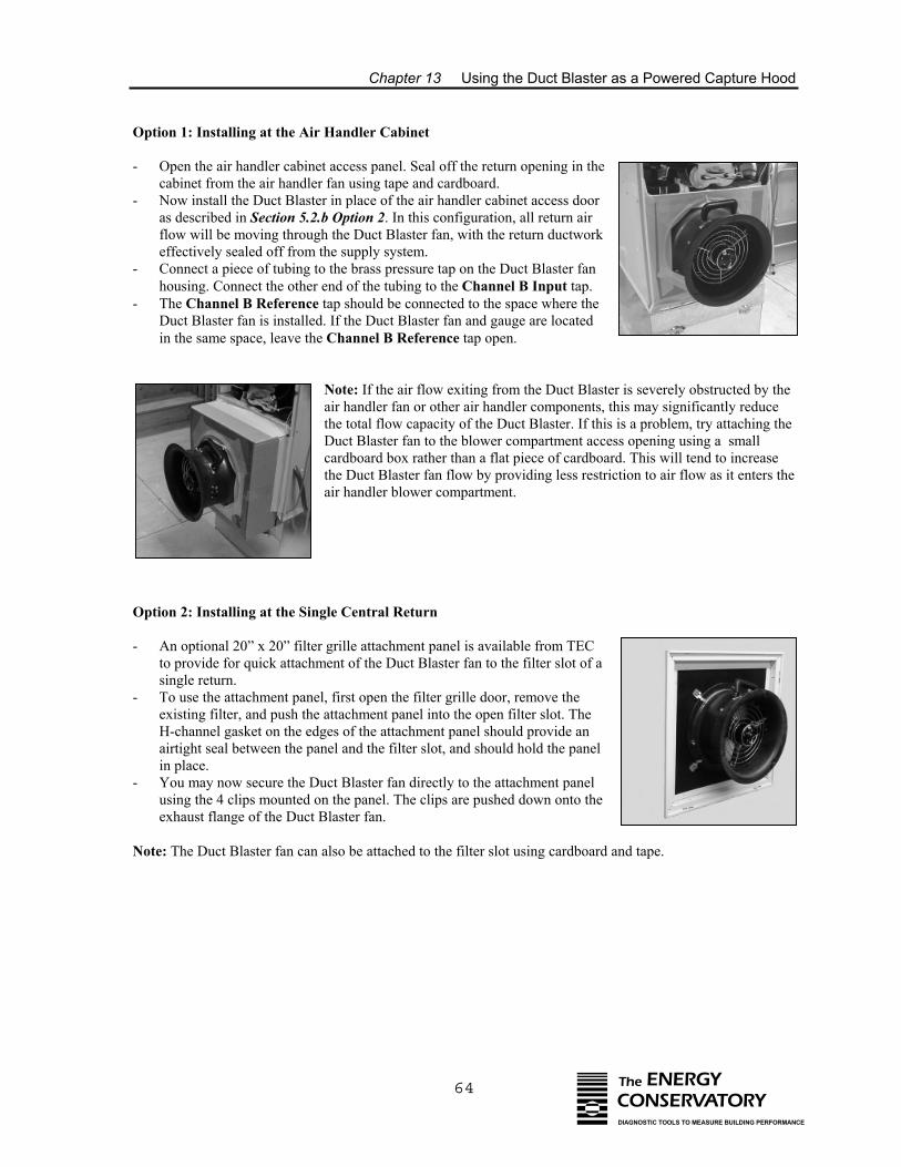
Chapter 13 Using the Duct Blaster as a Powered Capture Hood
64 The ENERGYCONSERVATORYDIAGNOSTIC TOOLS TO MEASURE BUILDING PERFORMANCE
Option 1: Installing at the Air Handler Cabinet
- Open the air handler cabinet access panel. Seal off the return opening in thecabinet from the air handler fan using tape and cardboard.
- Now install the Duct Blaster in place of the air handler cabinet access dooras described in Section 5.2.b Option 2. In this configuration, all return airflow will be moving through the Duct Blaster fan, with the return ductworkeffectively sealed off from the supply system.
- Connect a piece of tubing to the brass pressure tap on the Duct Blaster fanhousing. Connect the other end of the tubing to the Channel B Input tap.
- The Channel B Reference tap should be connected to the space where theDuct Blaster fan is installed. If the Duct Blaster fan and gauge are locatedin the same space, leave the Channel B Reference tap open.
-
-
-
Note: If the air flow exiting from the Duct Blaster is severely obstructed by theair handler fan or other air handler components, this may significantly reducethe total flow capacity of the Duct Blaster. If this is a problem, try attaching theDuct Blaster fan to the blower compartment access opening using a smallcardboard box rather than a flat piece of cardboard. This will tend to increasethe Duct Blaster fan flow by providing less restriction to air flow as it enters theair handler blower compartment.
Option 2: Installing at the Single Central Return
An optional 20” x 20” filter grille attachment panel is available from TECto provide for quick attachment of the Duct Blaster fan to the filter slot of asingle return.To use the attachment panel, first open the filter grille door, remove theexisting filter, and push the attachment panel into the open filter slot. TheH-channel gasket on the edges of the attachment panel should provide anairtight seal between the panel and the filter slot, and should hold the panelin place. You may now secure the Duct Blaster fan directly to the attachment panelusing the 4 clips mounted on the panel. The clips are pushed down onto theexhaust flange of the Duct Blaster fan.
Note: The Duct Blaster fan can also be attached to the filter slot using cardboard and tape.
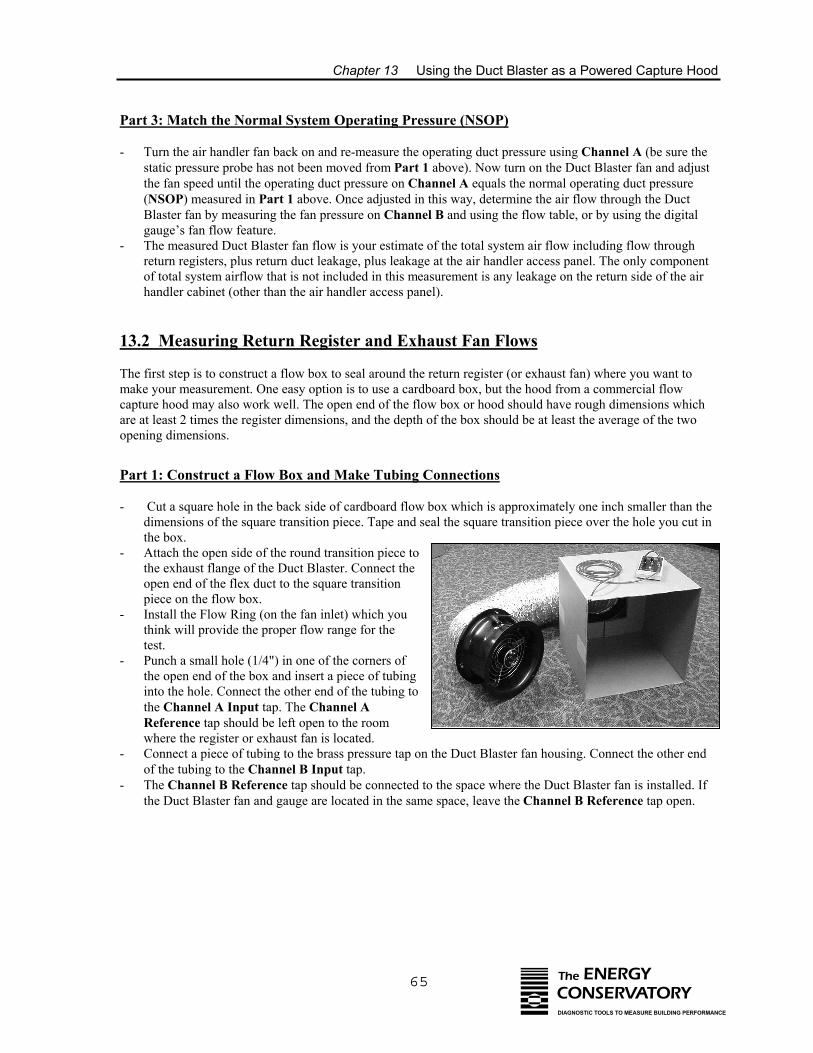
Chapter 13 Using the Duct Blaster as a Powered Capture Hood
65 The ENERGYCONSERVATORYDIAGNOSTIC TOOLS TO MEASURE BUILDING PERFORMANCE
Part 3: Match the Normal System Operating Pressure (NSOP)
- Turn the air handler fan back on and re-measure the operating duct pressure using Channel A (be sure thestatic pressure probe has not been moved from Part 1 above). Now turn on the Duct Blaster fan and adjustthe fan speed until the operating duct pressure on Channel A equals the normal operating duct pressure(NSOP) measured in Part 1 above. Once adjusted in this way, determine the air flow through the DuctBlaster fan by measuring the fan pressure on Channel B and using the flow table, or by using the digitalgauge’s fan flow feature.
- The measured Duct Blaster fan flow is your estimate of the total system air flow including flow throughreturn registers, plus return duct leakage, plus leakage at the air handler access panel. The only componentof total system airflow that is not included in this measurement is any leakage on the return side of the airhandler cabinet (other than the air handler access panel).
13.2 Measuring Return Register and Exhaust Fan Flows
The first step is to construct a flow box to seal around the return register (or exhaust fan) where you want tomake your measurement. One easy option is to use a cardboard box, but the hood from a commercial flowcapture hood may also work well. The open end of the flow box or hood should have rough dimensions whichare at least 2 times the register dimensions, and the depth of the box should be at least the average of the twoopening dimensions.
Part 1: Construct a Flow Box and Make Tubing Connections
- Cut a square hole in the back side of cardboard flow box which is approximately one inch smaller than thedimensions of the square transition piece. Tape and seal the square transition piece over the hole you cut inthe box.
- Attach the open side of the round transition piece tothe exhaust flange of the Duct Blaster. Connect theopen end of the flex duct to the square transitionpiece on the flow box.
- Install the Flow Ring (on the fan inlet) which youthink will provide the proper flow range for the test.
- Punch a small hole (1/4") in one of the corners ofthe open end of the box and insert a piece of tubinginto the hole. Connect the other end of the tubing tothe Channel A Input tap. The Channel AReference tap should be left open to the roomwhere the register or exhaust fan is located.
- Connect a piece of tubing to the brass pressure tap on the Duct Blaster fan housing. Connect the other endof the tubing to the Channel B Input tap.
- The Channel B Reference tap should be connected to the space where the Duct Blaster fan is installed. Ifthe Duct Blaster fan and gauge are located in the same space, leave the Channel B Reference tap open.
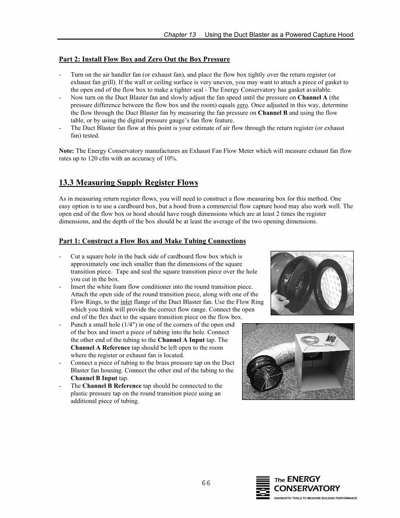
Chapter 13 Using the Duct Blaster as a Powered Capture Hood
66 The ENERGYCONSERVATORYDIAGNOSTIC TOOLS TO MEASURE BUILDING PERFORMANCE
Part 2: Install Flow Box and Zero Out the Box Pressure
- Turn on the air handler fan (or exhaust fan), and place the flow box tightly over the return register (orexhaust fan grill). If the wall or ceiling surface is very uneven, you may want to attach a piece of gasket tothe open end of the flow box to make a tighter seal - The Energy Conservatory has gasket available.
- Now turn on the Duct Blaster fan and slowly adjust the fan speed until the pressure on Channel A (thepressure difference between the flow box and the room) equals zero. Once adjusted in this way, determinethe flow through the Duct Blaster fan by measuring the fan pressure on Channel B and using the flowtable, or by using the digital pressure gauge’s fan flow feature.
- The Duct Blaster fan flow at this point is your estimate of air flow through the return register (or exhaustfan) tested.
Note: The Energy Conservatory manufactures an Exhaust Fan Flow Meter which will measure exhaust fan flowrates up to 120 cfm with an accuracy of 10%.
13.3 Measuring Supply Register Flows As in measuring return register flows, you will need to construct a flow measuring box for this method. Oneeasy option is to use a cardboard box, but a hood from a commercial flow capture hood may also work well. Theopen end of the flow box or hood should have rough dimensions which are at least 2 times the registerdimensions, and the depth of the box should be at least the average of the two opening dimensions.
Part 1: Construct a Flow Box and Make Tubing Connections
- Cut a square hole in the back side of cardboard flow box which isapproximately one inch smaller than the dimensions of the squaretransition piece. Tape and seal the square transition piece over the holeyou cut in the box.
- Insert the white foam flow conditioner into the round transition piece.Attach the open side of the round transition piece, along with one of theFlow Rings, to the inlet flange of the Duct Blaster fan. Use the Flow Ringwhich you think will provide the correct flow range. Connect the openend of the flex duct to the square transition piece on the flow box.
- Punch a small hole (1/4") in one of the corners of the open endof the box and insert a piece of tubing into the hole. Connectthe other end of the tubing to the Channel A Input tap. TheChannel A Reference tap should be left open to the roomwhere the register or exhaust fan is located.
- Connect a piece of tubing to the brass pressure tap on the DuctBlaster fan housing. Connect the other end of the tubing to theChannel B Input tap.
- The Channel B Reference tap should be connected to theplastic pressure tap on the round transition piece using anadditional piece of tubing.

Chapter 13 Using the Duct Blaster as a Powered Capture Hood
67 The ENERGYCONSERVATORYDIAGNOSTIC TOOLS TO MEASURE BUILDING PERFORMANCE
Part 2: Install Flow Box and Zero Out the Box Pressure
- Turn on the air handler fan and place the flow box tightly over the supply register. If the wall or ceilingsurface is very uneven, you may want to attach a piece of gasket to the open end of the flow box to make atighter seal - The Energy Conservatory has gasket available.
- Make sure that flex duct is stretched relatively straight (for about 4 feet) where the flex duct is connected tothe Duct Blaster fan.
- Now turn on the Duct Blaster fan and slowly adjust the fan speed until the pressure on Channel A (thepressure difference between the flow box and the room) equals zero. Once adjusted in this way, determinethe flow through the Duct Blaster fan by measuring the fan pressure on Channel B and using the flowtable, or by using the digital gauge’s fan flow feature.
- The Duct Blaster fan flow at this point is your estimate of air flow through the supply register tested.
Chapter 14 Pressure Balancing and System Performance Testing
68 The ENERGYCONSERVATORYDIAGNOSTIC TOOLS TO MEASURE BUILDING PERFORMANCE
Chapter 14 Pressure Balancing and System Performance Testing
14.1 Testing for Pressure Imbalances Caused By Forced Air System Flows
Air handler fans commonly move 500 to 2,000 cubic feet of air per minute (CFM). Pressure imbalances withinthe building can be caused by air hander fan operation if supply and return air flows to each part of the buildingare not in balance. Pressure imbalances within the building can significantly increase infiltration rates,contribute to radon and moisture entry, create durability problems, and cause potential combustion appliancespillage and backdrafting. In addition, research on combustion appliances has found that very small negativepressures (as low as 2 Pascals) can cause spillage and backdrafting in natural draft appliances.
Building pressure imbalances can also be caused by duct leakage to the outside. If either the supply or return airductwork has leaks to the outside, air will be forced through these leaks when the air handler fan is operating. Ifthe leaks are in the supply ducts, building air will be exhausted to the outside through the leaks and this willtend to depressurize the building. If the leaks are in the return system, outside air will be sucked into the leaksand the building will tend to be pressurized. If there are equal amounts of leakage in both the supply and return,no change in building pressure will occur, even though large energy losses may result.
Below are a set of test procedures used to help identify pressure imbalances caused by leaks between the ductsystem and the outside, and by imbalanced supply and return air flows throughout a building. These tests arevery sensitive to wind effects, and on windy days it can be very difficult to get accurate results.
14.1.a Dominant Duct Leak Test:
This test measures whole building pressurization or depressurization caused by duct leakage to the outsideduring operation of the air handler fan. A pressure change due to duct leakage can cause safety, durability,comfort, and efficiency problems.
- Be sure all exterior doors and windows in the building are closed. Replace all HVAC filters (be sure theyare clean). Open all interior doors and check that all exhaust fans and the air handler fan are off.
- Set up the digital pressure gauge to measure the building pressure With Respect To (WRT) outside.Connect tubing from the bottom (Reference) pressure tap on Channel A to the outside. The Channel Ainput tap should remain open to the building. Set up the gauge to measure pressures.
- Turn on the air handler fan and record the change in building pressure caused by operation of the fan. Note: The DG-700 gauge has a built-in “Baseline” feature which makes it easy to zero out the existingbuilding baseline pressure and display the actual change in building pressure caused by turning on the airhandler fan. See the DG-700 manual for specific operating instructions.
- Repeat this test several times by turning the air handler on and off for better certainty.
• Greater leakage on the return side of the duct system will cause the building to become pressurized sincethe return ductwork is drawing outside air into the ductwork. In this case, there will be a positive reading onpressure gauge. The size of the pressure change will depend on both the amount of imbalanced duct leakageand the tightness of the building being tested (see Figure 5 in Chapter 15).
• Greater leakage on the supply side of the system will cause the building to become depressurized since thesupply ductwork is exhausting building air to the outside, just like an exhaust fan. In this case, there will bea negative reading on the pressure gauge. The size of the pressure change will depend on both the amountof imbalanced duct leakage and the tightness of the building being tested (see Figure 5 in Chapter 15).
Chapter 14 Pressure Balancing and System Performance Testing
69 The ENERGYCONSERVATORYDIAGNOSTIC TOOLS TO MEASURE BUILDING PERFORMANCE
In cold climates, pressurizing a building to even 1 Pascal could lead to moisture problems caused by forcingwarm, moist air into the walls and attic where it can condense on cold surfaces. In warm humid climates,depressurization by 1 Pa can also cause severe moisture problems from warm moist outside air being drawn intothe walls where it can condense on the backside of cooled gypsum board. If there are natural draft combustionappliances, or if radon is a problem, depressurizing a building by as little as 2 Pascals may also be a problem.
If there is no change in building pressure, this means that there is either equal supply and return leakage to theoutside, no leaks to the outside, or the building itself is too leaky for the imbalanced duct leakage to create ameasurable pressure change.
Note: For APT users, a prototype software program called ONOFF is available to help precisely measure smallchanges in building or room pressures. The program uses a signal averaging technique which significantlyreduces noise, particularly in windy weather, allowing for precise measurement of small pressure changes.Contact The Energy Conservatory for more information.
14.1.b Master Suite Door Closure:
This test measures the effect of closing the master suite door on the pressure in the main body of the building.The master bedroom is often the largest room in a building and can contain multiple supply registers whilehaving no returns. Closing of bedroom doors can restrict the supply air pathway back to the air handler, causingbedrooms to become pressurized while other parts of the building may become depressurized. Repeat this testfor other building areas that contain large numbers of registers and can be closed off from the main body of thebuilding with one door (e.g. a basement door when the basement has supply registers).
- Keep the gauge set up to measure the pressure between the main body of the building WRT outside.- With air handler still running, close the master suite door.- Record the pressure change caused by closing the master suite door. (Large impacts from Master Suite
Door Closure are most common in single and double return houses.)- Consider pressure relief if the Master Suite door is frequently closed and causes the pressure in the main
body of the building to change by 1 Pascal or more in either direction.
14.1.c All Interior Doors Closed:
This test measures the added effect of closing all interior doors on the pressure in the main body of the building.
- Keep the gauge set up to measure the pressure between the main body of the building WRT outside.- With the air handler still running, close all interior doors.- Record the pressure change caused by closing all interior doors. - Consider pressure relief if closing all the doors causes the pressure in the main body of the building to
change by 2 Pascals or more in either direction.
14.1.d Room to Room Pressures:
This test measures the pressure difference between each room in the building and the main body, with the airhandler operating. Excessive pressurization in rooms can create durability problems by driving moisture intowalls, ceilings and floors. Excessive depressurization in rooms can pull outside moisture into buildingcomponents in humid climates. Pressure imbalances can also lead to large increases in building infiltration rates.
Chapter 14 Pressure Balancing and System Performance Testing
70 The ENERGYCONSERVATORYDIAGNOSTIC TOOLS TO MEASURE BUILDING PERFORMANCE
- Close all interior doors and walk around the building with the digital pressure gauge. - Connect a piece of tubing to the Channel A Input tap and leave the Channel A Reference tap open to the
room.- While standing in the main body of the building, place the open end of the tubing under each door
(including the combustion appliance room and/or basement). - Record the pressure difference from each room WRT the main body. - Consider pressure relief for any rooms pressurized or depressurized by 3 Pa or more with respect to the
main body of the building. Note: If there are combustion appliances in a depressurized area (i.e. fireplaces, furnace or water heater), theirability to draft properly may be affected. Try to eliminate all depressurization in combustion appliance zones byfinding and sealing leaks in the return ducts, plenum, filter access door and air handler cabinet, or by providingpressure relief. See Chapter 15 for more information on Combustion Safety Testing procedures.
14.2 System Performance Testing
Although not covered in this manual, other important test procedures should be performed whenever repairs andchanges are made to the duct system.
14.2 a Total System Air Flow:
The air flow rate through air handlers is a very important variable in estimating and optimizing the performanceof heat pumps, air conditioners and furnaces. Many studies of residential systems have shown low air flow to bea common problem. In addition, sealing duct leaks will commonly result in reduced total system air flow,especially if the duct system is sized improperly.
There are a number of methods to measure total system air flow including the Duct Blaster® pressure matchingmethod (see Chapter 13), the temperature rise method, system static pressure and fan curve, as well as a newdirect flow measuring tool (TrueFlow™ Air Handler Flow Meter) available from TEC. If the duct system issubstantially airtight, directly measuring supply or return air flows with a calibrated flow capture hood may alsobe used to estimate total system airflow.
Note: Research has shown that in most cases, the temperature rise, fan curve and flow capture hood methodsare much less accurate than either the Duct Blaster or TrueFlow methods.
14.2.b System Charge:
Having the proper amount of refrigerant installed in a heat pump or air conditioning system is another criticalvariable in determining system efficiency, as well the longevity of the system compressor. Numerous studieshave shown the incorrect amount of system charge to be a common installation problem.
14.2.c Airflow Balancing:
Verification that proper air flow is being delivered to each room in a building is another important component ofa complete system assessment. Air flow rates are commonly measured using a calibrated flow capture hood.
Chapter 15 Combustion Safety Testing
71 The ENERGYCONSERVATORYDIAGNOSTIC TOOLS TO MEASURE BUILDING PERFORMANCE
Chapter 15 Combustion Safety Testing
15.1 Overview
Buildings with natural draft combustion appliances should be routinely tested to ensure that the spillage ofcombustion products into the building is unlikely. Combustion safety testing is critical because of the potentialfor severe health effects from improperly venting appliances, including carbon monoxide poisoning.
Spillage of combustion products into the building can be caused by a variety of conditions including:
• Blocked or partially blocked chimneys, vents, or vent connectors.• Improper equipment installation.• Cracked heat exchangers. • Leaks in the venting system (disconnected flue pipes, open cleanest door etc.).• Low vent temperatures.• Combustion appliance zone depressurization. As buildings are made tighter, it becomes easier for exhaust
fans and forced air system imbalances to create potentially hazardous depressurization conditions.
Many cases of improperly venting combustion appliances have been related to depressurization (or negativepressures) in the room that contains the combustion appliance. Depressurization can be caused by exhaust fans,dryers, imbalanced forced air distribution systems, and forced air system duct leakage. As buildings (orcombustion appliance rooms) are made tighter, these problems can be made worse, although very leakybuildings can also have venting problems related to depressurization. Figure 5 below estimates the amount ofdepressurization that can be caused by various exhaust fan flows. For example, from Figure 5 we can see that a400 cfm exhaust fan will depressurize a 2,500 CFM50 building (or room) to approximately 3 Pascals. That same400 cfm fan would produce over 10 Pascals of depressurization in a 1,000 CFM50 building.
The presence of code approved combustion air intakes does not ensure that venting problems will not occur. Significant combustion room depressurization is frequently found even after code approved combustion airintakes have been installed. Passive combustion room air intakes typically do not provide sufficient airflow torelieve negative pressures caused by distribution imbalances, duct leakage, or large exhaust appliances. Forexample, a typical 6" passive inlet can at best supply only about 50 cfm at a 5 Pa negative building pressure.And because passive air intakes are often poorly installed (i.e. many sharp bends, long runs), they typicallyprovide much lower flows than designed. Building codes typically give little or no guidance on how one woulddesign a combustion air opening when competing exhaust appliances are present (the 2000 Minnesota EnergyCode is the only code we are aware of to give such guidance).
The only way to be reasonably sure that venting problems will not occur in a building is to perform combustionsafety tests. Described below is a test procedure designed to locate existing or potential combustion safetyproblems in buildings. These procedures are offered only as an example of what other organizations inNorth America typically recommend for testing. The Energy Conservatory assumes no liability for theiruse, and contractors should have a working knowledge of local codes and practices before attempting touse the procedures outlined below.
If combustion safety problems are found, tenants and building owners should be notified immediately and stepstaken to correct the problem including notifying a professional heating contractor if basic remedial actions arenot available. Remember, the presence of elevated levels of carbon monoxide in ambient building air or incombustion products is a potentially life threatening situation. Building or duct sealing work should not beundertaken until existing combustion safety problems are resolved, or unless air sealing is itself beingused as a remedial action.
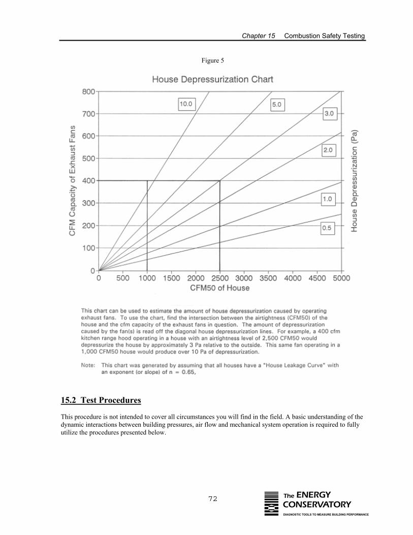
Chapter 15 Combustion Safety Testing
72 The ENERGYCONSERVATORYDIAGNOSTIC TOOLS TO MEASURE BUILDING PERFORMANCE
Figure 5
15.2 Test Procedures
This procedure is not intended to cover all circumstances you will find in the field. A basic understanding of thedynamic interactions between building pressures, air flow and mechanical system operation is required to fullyutilize the procedures presented below.
Chapter 15 Combustion Safety Testing
73 The ENERGYCONSERVATORYDIAGNOSTIC TOOLS TO MEASURE BUILDING PERFORMANCE
15.2.a Measure Ambient CO Level in Building:
- Zero your digital CO tester outside before entering the building. CO tester should have 1 PPM resolution.- Measure the ambient CO level in all occupied areas of the building. Be sure to measure ambient CO levels
in kitchens and in combustion appliance rooms. - Investigate any ambient CO levels above 2 ppm. Note: Areas close to very busy streets may have ambient
CO levels above 2 ppm. - Maximum CO concentration guidelines: 9 ppm for 8 hour exposure (EPA) 35 ppm for 1 hour exposure (EPA)
200 ppm single exposure (OSHA)
CO concentrations at or above these levels requires immediate remedial action.
15.2.b Survey of Combustion Appliances: - Walk through the building and survey all combustion appliances including furnaces, water heaters,
fireplaces, woodstove and auxiliary heating units, dryers and cooking stoves. - Write down the following information on a survey form:
• Location, type and input of combustion appliances.• Signs of visible deterioration and leaks in flue pipes and connections.• Presence of gas leaks, signs of spillage or flame roll-out.• Location, size and operable condition of combustion air supply(s).• Evidence of rusted interior surfaces of heat exchangers.
Gas or fuel leaks are a very serious safety problem requiring immediate remedial action.
15.2.c Survey of Exhaust Fans:
- Walk through building and note the location and rated capacity (or estimated capacity) of all exhaust fansincluding kitchen and stove fans, bath fans, dryers, whole house vacuum systems, attic vent fans (notincluding whole house ventilation fans) etc.
15.2.d Measure Worst Case Fan Depressurization:
With this test procedure, the goal is to measure worst case depressurization in all combustion rooms with naturaldraft appliances and fireplaces. This measurement gives us an indication of the likelihood of exhaust and airhandler fans causing the combustion appliances to backdraft and spill. The procedures below measure worstcase depressurization under 3 separate operating conditions; running exhaust fans only, running exhaust and airhandler fans, and running the air handler fan only. These tests are very sensitive to wind effects, and on windydays it can be very difficult to get accurate results.
Initial Preparation
Close all exterior windows and doors and be sure furnace, water heater and other vented combustion appliancesare off. Close all interior doors. Set up the digital gauge to measure the pressure difference of the combustionappliance zone (CAZ) with reference to (WRT) outside. Record the existing baseline building pressure. Note:The DG-700 gauge has a built-in “Baseline” feature which makes it easy to zero out the existing buildingbaseline pressure and display the actual change in building pressure caused by fan operation. See the DG-700manual for specific operating instructions.
Chapter 15 Combustion Safety Testing
74 The ENERGYCONSERVATORYDIAGNOSTIC TOOLS TO MEASURE BUILDING PERFORMANCE
1. Exhaust Fans Only
Turn on all exhaust fans found in the survey above (for dryer, clean out lint filter before turning on). Nowdetermine the worst case position of interior doors with the smoke test below:
Smoke Test: While standing in the main body of the building, squirt smoke under each doorcontaining an exhaust fan (except the CAZ currently being tested). If the smoke goes into the room,open the door. If the smoke comes back into the main body of the building, keep the door closed. Now squirt smoke under the CAZ door (while continuing to stand in the main body). If smoke goesinto the CAZ, leave the CAZ door shut. If smoke comes back into the main body of the building, openthe door.
Measure the depressurization of the CAZ WRT outside caused by turning on the exhaust fans (i.e. the change inbuilding pressure from the baseline condition). Depressurization should not exceed the appropriate HouseDepressurization Limits (HDL) listed in Table 9 below. If it is windy, it is often necessary to turn fans off andon several times to obtain good pressure readings.
Fireplace Zones: For Fireplace Zones, repeat the same procedure and measure and recorddepressurization of fireplace zone WRT outside from exhaust fan operation. Depressurization shouldnot exceed the appropriate HDL listed below.
2. Air Handler and Exhaust Fans
With exhaust fans continuing to run, turn on the air handler fan (note: air handler fan only, do not turn onburner) and close any supply registers in combustion appliance room. For both CAZ and Fireplace Zone tests,re-determine worst case position of all interior doors with the smoke test described above. If cooling isavailable, be sure air handler fan is running at high speed. Repeat worst case depressurization measurements.
3. Air Handler Fan Only
Turn off all exhaust fans and leave air handler operating (if cooling is available, be sure air handler is running athigh speed). For both CAZ and Fireplace Zone tests, re-determine worst case position of all interior doors withthe smoke test described above. Repeat worst case depressurization measurements.
If the HDL are exceeded for any of the worst case depressurization tests above, pressure relief isneeded. Pressure relief could include duct system repair, undercutting of doors, installation of transfergrills, eliminating or reducing exhaust fan capacity, or instructing homeowner on safe exhaust fanoperation. If negative pressures in the combustion appliance zone (or basement) are a function ofreturn leaks in that area, check for leaks in the return ductwork, plenum, filter access door and airhandler cabinet. Pay particular attention to panned under floor joists (used as returns) as they typicallyhave many leaks.
Note: For APT users, a prototype software program called ONOFF is available to help precisely measure smallchanges in building or room pressures. The program uses a signal averaging technique which significantlyreduces noise, particularly in windy weather, allowing for precise measurement of small pressure changes.Contact The Energy Conservatory for more information.
Chapter 15 Combustion Safety Testing
75 The ENERGYCONSERVATORYDIAGNOSTIC TOOLS TO MEASURE BUILDING PERFORMANCE
Table 9: House Depressurization Limits (HDL)
Appliance Type Depressurization Limit Individual natural draft water heater (WH) 2 PascalsNatural draft WH and natural draftfurnace/boiler
3 Pascals
Natural draft WH and Induced Draft (ID)furnace/boiler
5 Pascals
Individual natural draft furnace/boiler 5 PascalsIndividual ID furnace/boiler 15 PascalsPower vented and sealed combustion appliances >25 Pascals
Source: CEE Appliance Safety Test Methods, MAC Part 150 Residential Sound Insulation Program, Mpls, MN.
15.2.e Spillage Test (natural draft and induced draft appliances):
This test identifies actual spillage of combustion byproducts into the living space under worst casedepressurization conditions.
- With building set up in worst case depressurization mode (as specified above), fire up each combustionappliance.
- If appliances are common vented, conduct test on smallest input appliance first, then test with bothappliances running.
- When burner lights, check for flame rollout (stand away from burner).- Check for spillage (using chemical smoke) at the end of the spillage test period (see Table 10 below). For
natural draft appliances, spillage is tested at the draft divertor. When an induced draft heating system isvented in common with a natural draft water heater, spillage is checked at the water heater draft divertor.For a single induced draft appliance, spillage is checked at the base of the chimney liner or flue, typicallyusing the drip tee at the bottom of the liner.
Table 10: Spillage Test Period
Appliance Type Spillage Test Period (minutes)Water heater, gravity furnaceand boiler
3.0 minutes
Space heater 2.0 minutesFurnace 1.0 minutes
Source: CEE Appliance Safety Test Methods, MAC Part 150 Residential Sound Insulation Program, Mpls, MN.
- If spillage continues beyond the spillage test period, remove the negative pressure in combustion room byturning off fans and/or opening an exterior window or door.
- Re-check for spillage. If spillage stops, there is a pressure induced spillage problem. If spillage continues,check flue and chimney for obstructions, and check compatibility of appliance BTU input with chimneysize.
Spillage of combustion products beyond the spillage test period is a health and safety concern. If theproblem is a blocked flue or chimney, or inadequately sized flue or chimney, consult a professionalheating contractor. If the problem is pressure induced, provide pressure relief. Re-check for spillagefollowing attempt to provide pressure relief. If spillage continues, contact a professional heatingcontractor to investigate the problem.
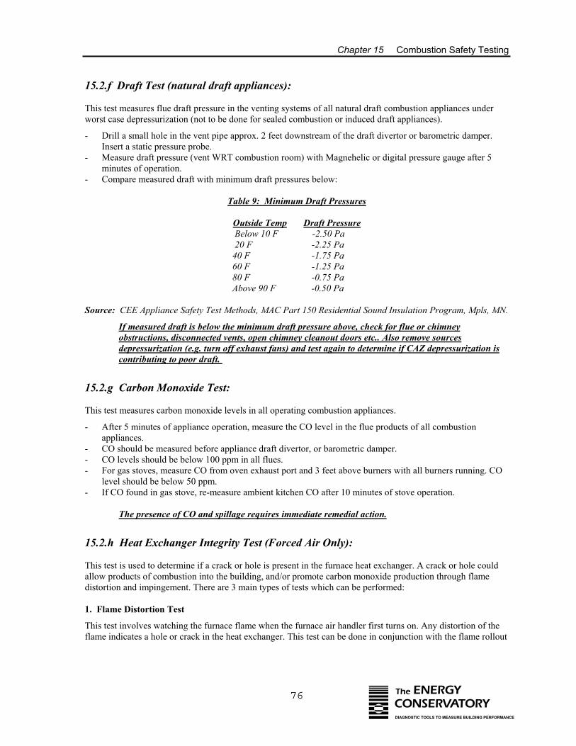
Chapter 15 Combustion Safety Testing
76 The ENERGYCONSERVATORYDIAGNOSTIC TOOLS TO MEASURE BUILDING PERFORMANCE
15.2.f Draft Test (natural draft appliances):
This test measures flue draft pressure in the venting systems of all natural draft combustion appliances underworst case depressurization (not to be done for sealed combustion or induced draft appliances).
- Drill a small hole in the vent pipe approx. 2 feet downstream of the draft divertor or barometric damper.Insert a static pressure probe.
- Measure draft pressure (vent WRT combustion room) with Magnehelic or digital pressure gauge after 5minutes of operation.
- Compare measured draft with minimum draft pressures below:
Table 9: Minimum Draft Pressures
Outside Temp Draft Pressure Below 10 F -2.50 Pa 20 F -2.25 Pa 40 F -1.75 Pa 60 F -1.25 Pa
80 F -0.75 Pa Above 90 F -0.50 Pa
Source: CEE Appliance Safety Test Methods, MAC Part 150 Residential Sound Insulation Program, Mpls, MN.
If measured draft is below the minimum draft pressure above, check for flue or chimneyobstructions, disconnected vents, open chimney cleanout doors etc.. Also remove sourcesdepressurization (e.g. turn off exhaust fans) and test again to determine if CAZ depressurization iscontributing to poor draft.
15.2.g Carbon Monoxide Test:
This test measures carbon monoxide levels in all operating combustion appliances.
- After 5 minutes of appliance operation, measure the CO level in the flue products of all combustionappliances.
- CO should be measured before appliance draft divertor, or barometric damper. - CO levels should be below 100 ppm in all flues.- For gas stoves, measure CO from oven exhaust port and 3 feet above burners with all burners running. CO
level should be below 50 ppm.- If CO found in gas stove, re-measure ambient kitchen CO after 10 minutes of stove operation.
The presence of CO and spillage requires immediate remedial action.
15.2.h Heat Exchanger Integrity Test (Forced Air Only):
This test is used to determine if a crack or hole is present in the furnace heat exchanger. A crack or hole couldallow products of combustion into the building, and/or promote carbon monoxide production through flamedistortion and impingement. There are 3 main types of tests which can be performed:
1. Flame Distortion Test
This test involves watching the furnace flame when the furnace air handler first turns on. Any distortion of theflame indicates a hole or crack in the heat exchanger. This test can be done in conjunction with the flame rollout
Chapter 15 Combustion Safety Testing
77 The ENERGYCONSERVATORYDIAGNOSTIC TOOLS TO MEASURE BUILDING PERFORMANCE
component of the spillage test. Another method for conducting a flame distortion test is to slowly extend amatch up and down into each combustion chamber with the burner off and the air handler fan on, and watch formovement of the flame head.
2. Blocked Flue Test
With the furnace off, block the flue ports leading from the combustion chamber to the draft divertor orbarometric damper. Squirt smoke into the combustion chamber. Turn on the furnace fan and watch to see if thesmoke is disturbed when the fan comes on. Smoke movement indicates a hole or crack in the heat exchanger.
3. Tracer Gas Test
A number of testing procedures exist for injecting a tracer gas into the combustion chamber (usually with thefurnace fan off) and then measuring or detecting the tracer gas on the warm air side of the heat exchanger.
If any of the above heat exchanger tests provides a positive indication for a cracked heat exchanger,immediate action should be taken to notify the residents of the potential danger, and a professionalheating contractor should be contacted to investigate the problem.
Turn off fans and return appliance controls to their original settings once the testprocedures have been completed.
Special thanks to Advanced Energy, Sun Power and the Center for Energy and Environment (CEE) for theirwork in developing and refining the combustion safety test procedures above.
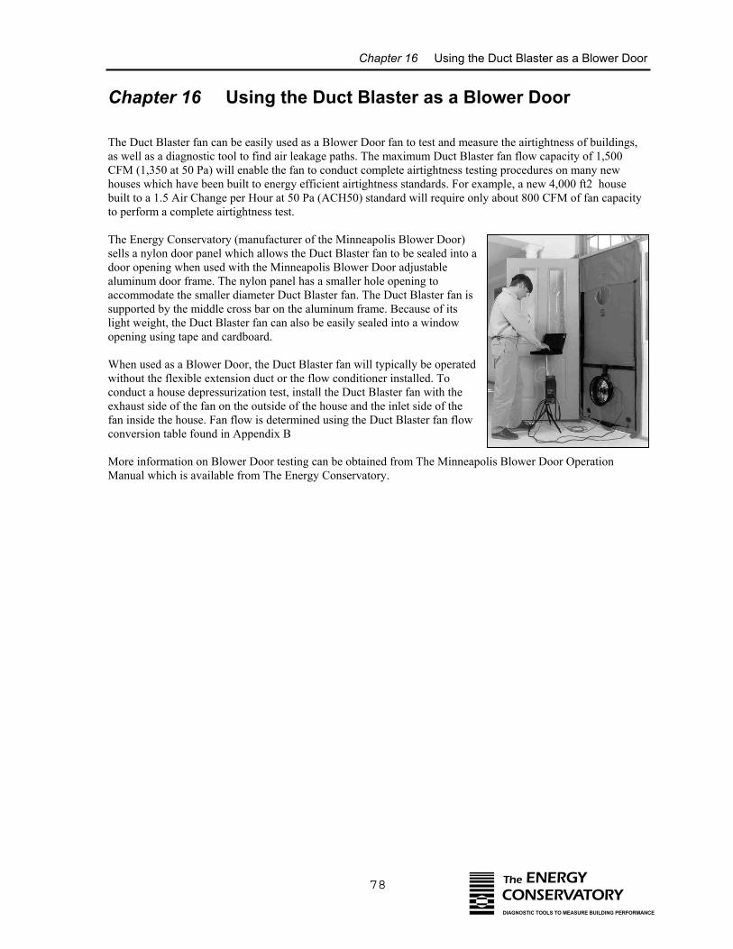
Chapter 16 Using the Duct Blaster as a Blower Door
78 The ENERGYCONSERVATORYDIAGNOSTIC TOOLS TO MEASURE BUILDING PERFORMANCE
Chapter 16 Using the Duct Blaster as a Blower Door
The Duct Blaster fan can be easily used as a Blower Door fan to test and measure the airtightness of buildings,as well as a diagnostic tool to find air leakage paths. The maximum Duct Blaster fan flow capacity of 1,500CFM (1,350 at 50 Pa) will enable the fan to conduct complete airtightness testing procedures on many newhouses which have been built to energy efficient airtightness standards. For example, a new 4,000 ft2 housebuilt to a 1.5 Air Change per Hour at 50 Pa (ACH50) standard will require only about 800 CFM of fan capacityto perform a complete airtightness test.
The Energy Conservatory (manufacturer of the Minneapolis Blower Door)sells a nylon door panel which allows the Duct Blaster fan to be sealed into adoor opening when used with the Minneapolis Blower Door adjustablealuminum door frame. The nylon panel has a smaller hole opening toaccommodate the smaller diameter Duct Blaster fan. The Duct Blaster fan issupported by the middle cross bar on the aluminum frame. Because of itslight weight, the Duct Blaster fan can also be easily sealed into a windowopening using tape and cardboard.
When used as a Blower Door, the Duct Blaster fan will typically be operatedwithout the flexible extension duct or the flow conditioner installed. Toconduct a house depressurization test, install the Duct Blaster fan with theexhaust side of the fan on the outside of the house and the inlet side of thefan inside the house. Fan flow is determined using the Duct Blaster fan flowconversion table found in Appendix B
More information on Blower Door testing can be obtained from The Minneapolis Blower Door OperationManual which is available from The Energy Conservatory.
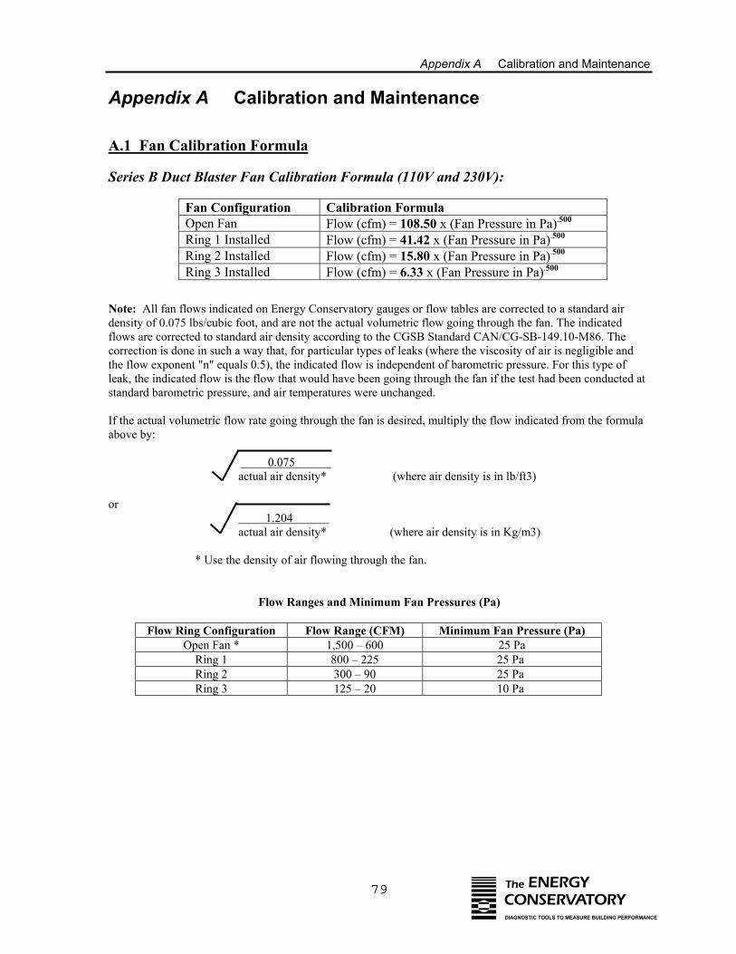
Appendix A Calibration and Maintenance
79 The ENERGYCONSERVATORYDIAGNOSTIC TOOLS TO MEASURE BUILDING PERFORMANCE
Appendix A Calibration and Maintenance
A.1 Fan Calibration Formula
Series B Duct Blaster Fan Calibration Formula (110V and 230V):
Fan Configuration Calibration FormulaOpen Fan Flow (cfm) = 108.50 x (Fan Pressure in Pa).500
Ring 1 Installed Flow (cfm) = 41.42 x (Fan Pressure in Pa).500
Ring 2 Installed Flow (cfm) = 15.80 x (Fan Pressure in Pa).500
Ring 3 Installed Flow (cfm) = 6.33 x (Fan Pressure in Pa).500
Note: All fan flows indicated on Energy Conservatory gauges or flow tables are corrected to a standard airdensity of 0.075 lbs/cubic foot, and are not the actual volumetric flow going through the fan. The indicatedflows are corrected to standard air density according to the CGSB Standard CAN/CG-SB-149.10-M86. Thecorrection is done in such a way that, for particular types of leaks (where the viscosity of air is negligible andthe flow exponent "n" equals 0.5), the indicated flow is independent of barometric pressure. For this type ofleak, the indicated flow is the flow that would have been going through the fan if the test had been conducted atstandard barometric pressure, and air temperatures were unchanged.
If the actual volumetric flow rate going through the fan is desired, multiply the flow indicated from the formulaabove by:
0.075 actual air density* (where air density is in lb/ft3)
or 1.204 actual air density* (where air density is in Kg/m3)
* Use the density of air flowing through the fan.
Flow Ranges and Minimum Fan Pressures (Pa)
Flow Ring Configuration Flow Range (CFM) Minimum Fan Pressure (Pa)Open Fan * 1,500 – 600 25 Pa
Ring 1 800 – 225 25 Pa Ring 2 300 – 90 25 Pa Ring 3 125 – 20 10 Pa
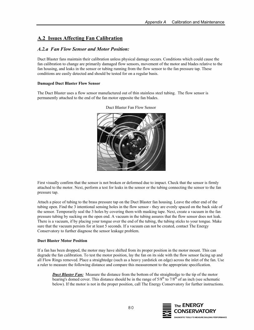
Appendix A Calibration and Maintenance
80 The ENERGYCONSERVATORYDIAGNOSTIC TOOLS TO MEASURE BUILDING PERFORMANCE
A.2 Issues Affecting Fan Calibration
A.2.a Fan Flow Sensor and Motor Position:
Duct Blaster fans maintain their calibration unless physical damage occurs. Conditions which could cause thefan calibration to change are primarily damaged flow sensors, movement of the motor and blades relative to thefan housing, and leaks in the sensor or tubing running from the flow sensor to the fan pressure tap. Theseconditions are easily detected and should be tested for on a regular basis.
Damaged Duct Blaster Flow Sensor
The Duct Blaster uses a flow sensor manufactured out of thin stainless steel tubing. The flow sensor ispermanently attached to the end of the fan motor opposite the fan blades.
Duct Blaster Fan Flow Sensor
First visually confirm that the sensor is not broken or deformed due to impact. Check that the sensor is firmlyattached to the motor. Next, perform a test for leaks in the sensor or the tubing connecting the sensor to the fanpressure tap.
Attach a piece of tubing to the brass pressure tap on the Duct Blaster fan housing. Leave the other end of thetubing open. Find the 3 intentional sensing holes in the flow sensor - they are evenly spaced on the back side ofthe sensor. Temporarily seal the 3 holes by covering them with masking tape. Next, create a vacuum in the fanpressure tubing by sucking on the open end. A vacuum in the tubing assures that the flow sensor does not leak.There is a vacuum, if by placing your tongue over the end of the tubing, the tubing sticks to your tongue. Makesure that the vacuum persists for at least 5 seconds. If a vacuum can not be created, contact The EnergyConservatory to further diagnose the sensor leakage problem.
Duct Blaster Motor Position
If a fan has been dropped, the motor may have shifted from its proper position in the motor mount. This candegrade the fan calibration. To test the motor position, lay the fan on its side with the flow sensor facing up andall Flow Rings removed. Place a straightedge (such as a heavy yardstick on edge) across the inlet of the fan. Usea ruler to measure the following distance and compare this measurement to the appropriate specification.
Duct Blaster Fan: Measure the distance from the bottom of the straightedge to the tip of the motorbearing's domed cover. This distance should be in the range of 5/8th to 7/8th of an inch (see schematicbelow). If the motor is not in the proper position, call The Energy Conservatory for further instructions.
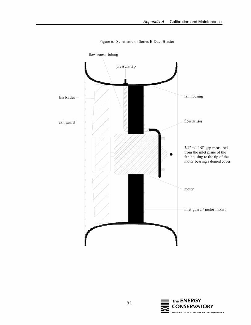
Appendix A Calibration and Maintenance
81 The ENERGYCONSERVATORYDIAGNOSTIC TOOLS TO MEASURE BUILDING PERFORMANCE
Figure 6: Schematic of Series B Duct Blaster
fan housing
flow sensor
motor
inlet guard / motor mount
exit guard
3/4" +/- 1/8" gap measured from the inlet plane of the fan housing to the tip of the motor bearing's domed cover
flow sensor tubing
fan blades
pressure tap
Appendix A Calibration and Maintenance
82 The ENERGYCONSERVATORYDIAGNOSTIC TOOLS TO MEASURE BUILDING PERFORMANCE
A.2.b Upstream Air Flow Conditions:
• When using the Duct Blaster fan to conduct a duct leakage depressurization test (i.e. the flex duct isconnected to the inlet side of the fan), always position the fan so that the flex duct is stretched relativelystraight for about 4 feet in front of the fan.
• When the fan inlet is open to the room, try to install the fan so that there is not a large obstruction within 2feet in front of the fan.
A.2.c Operating Under High Backpressure Conditions:
Note: For most testing applications, backpressure is not a concern and can be ignored.
The term "backpressure" is used to describe the pressure that the Duct Blaster fan is working against when it isrunning. Backpressure is determined by measuring the static pressure difference between the air directlyupstream of the fan, and the air directly exiting the fan. High backpressures are typically caused by a largerestriction between the Duct Blaster fan and the location where the test pressure is being made.
Although the Duct Blaster's flow sensor was carefully designed to be affected as little as possible by variationsin backpressure, under certain very high backpressure operating conditions (described below) the calibration ofthe fan can degrade.
Open Fan Configuration, Low Air Flow and High Backpressure
If the Duct Blaster fan is operated in the open fan configuration (i.e. no Flow Ring), with low air flow (i.e. lessthan 700 cfm), and high backpressure (i.e. greater than 150 Pascals), the flow measurement accuracy of the fancan be significantly diminished. Although unlikely to be encountered in the test applications described in thismanual, it is possible to set up the Duct Blaster system to create these conditions.
One example of an application that could cause high backpressure is when the flexible extension duct isconnected to a small, high resistance register. The high resistance register can cause the pressure in the flex ductto be very high (i.e. over 150 Pascals) even if the test pressure in the duct system is only 25 Pascals. Operatingthe Duct Blaster fan with no Flow Rings attached at very low flows is not advised under these operatingconditions.
To avoid this problem:
• Always use one of the Flow Rings whenever possible. When Flow Rings are attached to the fan, the fan canreliably measure air flow at very high backpressures.
• Always try to avoid connecting the Duct Blaster fan to the duct system using a relatively high resistanceconnection (such as a small supply or return register).
• If using the open fan configuration and measuring relatively low flows (less than 700 cfm), try to measurethe backpressure. If the measured backpressure is less than 5 times the fan pressure, then there should notbe a problem. Note: If the flexible extension duct is being used, the backpressure can be easily determinedby measuring the pressure difference between the room where the Duct Blaster fan is installed and pressureinside the flex duct (measured from the plastic tap on the round transition piece).
Appendix A Calibration and Maintenance
83 The ENERGYCONSERVATORYDIAGNOSTIC TOOLS TO MEASURE BUILDING PERFORMANCE
A.3 Duct Blaster Fan Maintenance and Safety
There are several maintenance tips and procedures to ensure the proper operation of the Duct Blaster fan and toavoid any safety risks.
A.3.a Maintenance Checks:
• Examine the motor cooling holes for excessive dust and dirt build-up. Use a vacuum with a brushattachment to remove dust, or blow out the dust with compressed air.
• Inspect housing, blades and guards. Especially note clearance of blade tips relative to the fan housing. There should be about 1/4 to 1/8 inch of clearance.
• Inspect electrical wiring and electrical connections on the fan and the fan speed controller.
A.3.b General Operational Notes and Tips:
• The Duct Blaster fan motor is not a continuous duty motor and should not be run for extended periods oftime (more than 2 hours at one time).
• The fan should not be left running unattended.• Do not use ungrounded outlets or adapter plugs.• Do not operate if the motor, controller or any of the electrical connections are wet.• Keep people and pets away from the fan when it is operating.
The Duct Blaster fan is a very powerful and potentially dangerous piece of equipment if not used andmaintained properly. Carefully examine the fan before each use. If the fan housing, fan guards, blade,controller or cords become damaged, do not operate the fan until repairs have been made. Contact The EnergyConservatory if there are any unusual noises or vibrations while the fan is running.
A.4 Calibration and Maintenance of Digital Pressure Gauges
A.4.a Digital Gauge Calibration:
Re-calibration of digital pressure gauges is recommended every 12 months. Gauges should be sent back to TheEnergy Conservatory for re-calibration. It is also a good idea to perform gauge comparisons betweencalibrations, especially when damage is suspected (e.g. when a gauge has been dropped).
Digital Gauge Comparison
This technique is used to compare the readings of two digital gauges when they are both connected to the samepressure source. When two gauges are being compared, you should expect them to agree within theirspecifications:
DG-3 Accuracy Specifications:
Low Range: +/- 1% of reading or 0.2 Pa, whichever is larger (0-200.0 Pa)High Range: +/- 1% of reading or 2 Pa, whichever is larger (0-800 Pa)
+/- 2% of reading (800-1,000 Pa)
DG-700 Accuracy Specifications:
+/- 1% of reading or 0.15 Pa, whichever is greater (0-1,250 Pa)
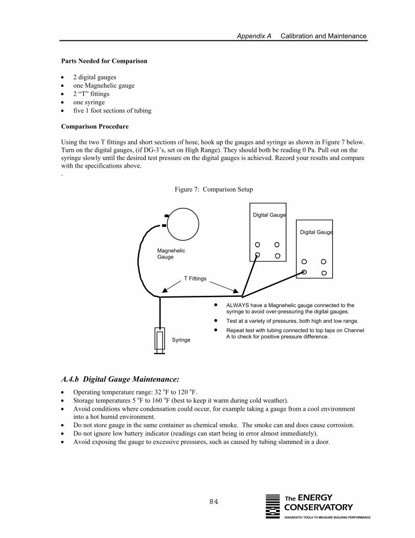
Appendix A Calibration and Maintenance
84 The ENERGYCONSERVATORYDIAGNOSTIC TOOLS TO MEASURE BUILDING PERFORMANCE
Parts Needed for Comparison
• 2 digital gauges• one Magnehelic gauge• 2 “T” fittings• one syringe • five 1 foot sections of tubing
Comparison Procedure
Using the two T fittings and short sections of hose, hook up the gauges and syringe as shown in Figure 7 below.Turn on the digital gauges, (if DG-3’s, set on High Range). They should both be reading 0 Pa. Pull out on thesyringe slowly until the desired test pressure on the digital gauges is achieved. Record your results and comparewith the specifications above. .
Figure 7: Comparison Setup
• • •
• • •
• ALWAYS have a Magnehelic gauge connected to thesyringe to avoid over-pressuring the digital gauges.
• Test at a variety of pressures, both high and low range.
• Repeat test with tubing connected to top taps on Channel A to check for positive pressure difference.
MagnehelicGauge
Digital Gauge
Syringe
Digital Gauge
T Fittings
A.4.b Digital Gauge Maintenance:Operating temperature range: 32 oF to 120 oF.Storage temperatures 5 oF to 160 oF (best to keep it warm during cold weather).Avoid conditions where condensation could occur, for example taking a gauge from a cool environmentinto a hot humid environment.Do not store gauge in the same container as chemical smoke. The smoke can and does cause corrosion.Do not ignore low battery indicator (readings can start being in error almost immediately).Avoid exposing the gauge to excessive pressures, such as caused by tubing slammed in a door.
Appendix A Calibration and Maintenance
85 The ENERGYCONSERVATORYDIAGNOSTIC TOOLS TO MEASURE BUILDING PERFORMANCE
A.5 Checking for Leaky Tubing
It does not happen very often, but leaky tubing can seriously degrade the accuracy of duct leakage tests. Theseleaks can be small enough to go undetected for years but large enough to affect fan calibration.
- Before starting, inspect both ends of the tubing to make sure they are not stretched out to the point wherethey will not make a good seal when attached to a gauge.
- Seal off one end of the tubing by doubling it over on itself near the end. - Create a vacuum in the tubing by sucking on the open end (make sure the hose is clean first!). Let the end
of the tubing stick to your tongue due to the vacuum. - The tubing should stick to your tongue indefinitely if there are no leaks. Waiting for 5 seconds or so is a
good enough test.- If the tubing has a leak, it should be replaced immediately.- The ends of the tubing will sometimes get stretched out or torn after many uses. Periodically trim 1/4" off
the ends of the tubing to remove the damaged end.
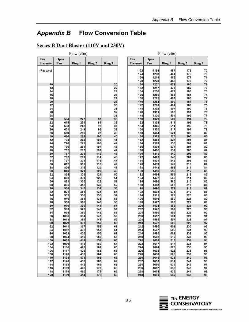
Appendix B Flow Conversion Table
Appendix B Flow Conversion Table
Series B Duct Blaster (110V and 230V) Flow (cfm) Flow (cfm)
Fan Pressure
Open Fan Ring 1 Ring 2 Ring 3
(Pascals)
10 2012 2214 2416 2518 2720 2822 3024 3126 3228 3330 594 227 87 3532 614 234 89 3634 633 242 92 3736 651 249 95 3838 669 255 97 3940 686 262 100 4042 703 268 102 4144 720 275 105 4246 736 281 107 4348 752 287 109 4450 767 293 112 4552 782 299 114 4654 797 304 116 4756 812 310 118 4758 826 315 120 4860 840 321 122 4962 854 326 124 5064 868 331 126 5166 881 336 128 5168 895 342 130 5270 908 347 132 5372 921 351 134 5474 933 356 136 5476 946 361 138 5578 958 366 140 5680 970 370 141 5782 983 375 143 5784 994 380 145 5886 1006 384 147 5988 1018 389 148 5990 1029 393 150 6092 1041 397 152 6194 1052 402 153 6196 1063 406 155 6298 1074 410 156 63
100 1085 414 158 63102 1096 418 160 64104 1106 422 161 65106 1117 426 163 65108 1128 430 164 66110 1138 434 166 66112 1148 438 167 67114 1158 442 169 68116 1169 446 170 68118 1179 450 172 69120 1189 454 173 69
Fan Pressure
Open Fan Ring 1 Ring 2 Ring 3
122 1198 457 175 70124 1208 461 176 70126 1218 465 177 71128 1228 469 179 72130 1237 472 180 72132 1247 476 182 73134 1256 479 183 73136 1265 483 184 74138 1275 487 186 74140 1284 490 187 75142 1293 494 188 75144 1302 497 190 76146 1311 500 191 76148 1320 504 192 77150 1329 507 194 78152 1338 511 195 78154 1346 514 196 79156 1355 517 197 79158 1364 521 199 80160 1372 524 200 80162 1381 527 201 81164 1389 530 202 81166 1398 534 204 82168 1406 537 205 82170 1415 540 206 83172 1423 543 207 83174 1431 546 208 83176 1439 549 210 84178 1448 553 211 84180 1456 556 212 85182 1464 559 213 85184 1472 562 214 86186 1480 565 215 86188 1488 568 217 87190 1496 571 218 87192 1503 574 219 88194 1511 577 220 88196 1519 580 221 89198 1527 583 222 89200 1534 586 223 90202 1542 589 225 90204 1550 592 226 90206 1557 594 227 91208 1565 597 228 91210 1572 600 229 92212 1580 603 230 92214 1587 606 231 93216 1595 609 232 93218 1602 612 233 93220 1609 614 234 94222 1617 617 235 94224 1624 620 236 95226 1631 623 238 95228 1638 625 239 96230 1645 628 240 96232 1653 631 241 96234 1660 634 242 97236 1667 636 243 97238 1674 639 244 98240 1681 642 245 98
86 The ENERGYCONSERVATORYDIAGNOSTIC TOOLS TO MEASURE BUILDING PERFORMANCE
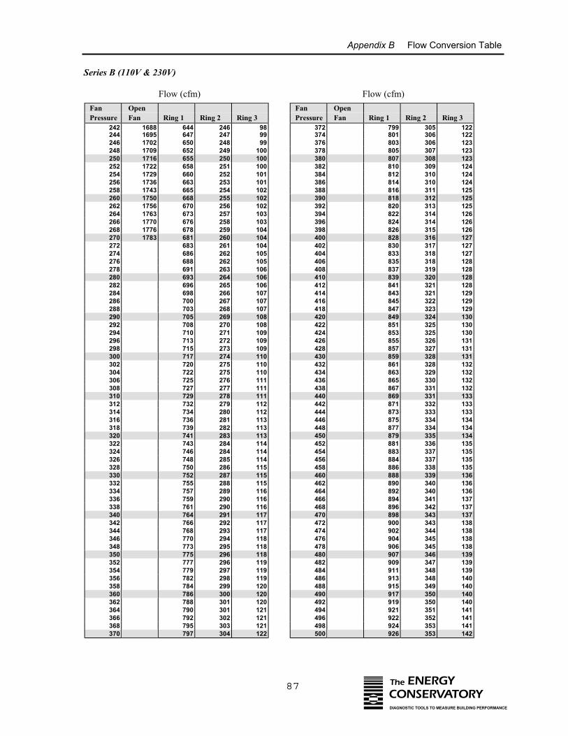
Appendix B Flow Conversion Table
Series B (110V & 230V)
Flow (cfm) Flow (cfm)
Fan PressureOpen Fan Ring 1 Ring 2 Ring 3
242 1688 644 246 98244 1695 647 247 99246 1702 650 248 99248 1709 652 249 100250 1716 655 250 100252 1722 658 251 100254 1729 660 252 101256 1736 663 253 101258 1743 665 254 102260 1750 668 255 102262 1756 670 256 102264 1763 673 257 103266 1770 676 258 103268 1776 678 259 104270 1783 681 260 104272 683 261 104274 686 262 105276 688 262 105278 691 263 106280 693 264 106282 696 265 106284 698 266 107286 700 267 107288 703 268 107290 705 269 108292 708 270 108294 710 271 109296 713 272 109298 715 273 109300 717 274 110302 720 275 110304 722 275 110306 725 276 111308 727 277 111310 729 278 111312 732 279 112314 734 280 112316 736 281 113318 739 282 113320 741 283 113322 743 284 114324 746 284 114326 748 285 114328 750 286 115330 752 287 115332 755 288 115334 757 289 116336 759 290 116338 761 290 116340 764 291 117342 766 292 117344 768 293 117346 770 294 118348 773 295 118350 775 296 118352 777 296 119354 779 297 119356 782 298 119358 784 299 120360 786 300 120362 788 301 120364 790 301 121366 792 302 121368 795 303 121370 797 304 122
Fan Pressure
Open Fan Ring 1 Ring 2 Ring 3
372 799 305 122374 801 306 122376 803 306 123378 805 307 123380 807 308 123382 810 309 124384 812 310 124386 814 310 124388 816 311 125390 818 312 125392 820 313 125394 822 314 126396 824 314 126398 826 315 126400 828 316 127402 830 317 127404 833 318 127406 835 318 128408 837 319 128410 839 320 128412 841 321 128414 843 321 129416 845 322 129418 847 323 129420 849 324 130422 851 325 130424 853 325 130426 855 326 131428 857 327 131430 859 328 131432 861 328 132434 863 329 132436 865 330 132438 867 331 132440 869 331 133442 871 332 133444 873 333 133446 875 334 134448 877 334 134450 879 335 134452 881 336 135454 883 337 135456 884 337 135458 886 338 135460 888 339 136462 890 340 136464 892 340 136466 894 341 137468 896 342 137470 898 343 137472 900 343 138474 902 344 138476 904 345 138478 906 345 138480 907 346 139482 909 347 139484 911 348 139486 913 348 140488 915 349 140490 917 350 140492 919 350 140494 921 351 141496 922 352 141498 924 353 141500 926 353 142
87 The ENERGYCONSERVATORYDIAGNOSTIC TOOLS TO MEASURE BUILDING PERFORMANCE
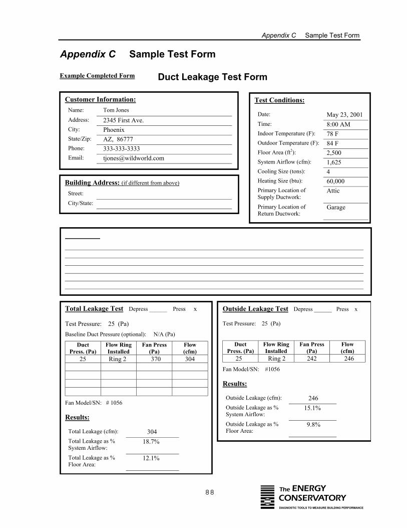
Appendix C Sample Test Form
88 The ENERGYCONSERVATORYDIAGNOSTIC TOOLS TO MEASURE BUILDING PERFORMANCE
Appendix C Sample Test Form
Example Completed Form Duct Leakage Test Form
Customer Information: Test Conditions:Name: Tom Jones
Date: May 23, 2001Address: 2345 First Ave. Time: 8:00 AMCity: Phoenix Indoor Temperature (F): 78 FState/Zip: AZ, 86777 Outdoor Temperature (F): 84 FPhone: 333-333-3333 Floor Area (ft2): 2,500Email: [email protected] System Airflow (cfm): 1,625
Cooling Size (tons): 4
Building Address: Heating Size (btu):(if different from above) 60,000Primary Location of AtticStreet: Supply Ductwork:
City/State: Primary Location of GarageReturn Ductwork:
Comments:Platform return in garage. Platform open to wall cavity. Single return.Flex duct in attic.
Total Leakage Test Depress ______ Press x Outside Leakage Test Depress ______ Press x
Test Pressure: 25 (Pa) Test Pressure: 25 (Pa)
Baseline Duct Pressure (optional): N/A (Pa)
Duct Flow Ring Fan Press Flow Duct Flow Ring Fan Press FlowPress. (Pa) Installed (Pa) (cfm) Press. (Pa) Installed (Pa) (cfm) 25 Ring 2 370 304 25 Ring 2 242 246
Fan Model/SN: #1056
Results:
Outside Leakage (cfm): 246Fan Model/SN: # 1056
Outside Leakage as % 15.1%Results: System Airflow:
Outside Leakage as % 9.8%Total Leakage (cfm): 304 Floor Area:
Total Leakage as % 18.7%System Airflow:
Total Leakage as % 12.1%Floor Area:
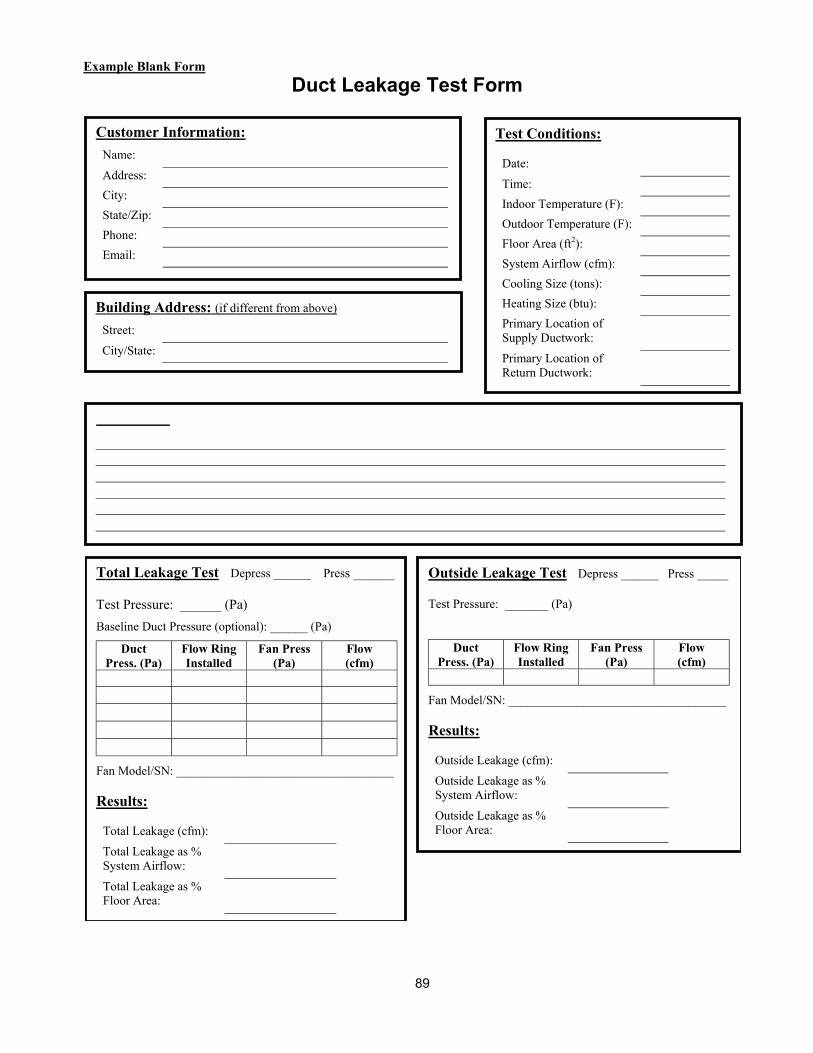
89
Example Blank FormDuct Leakage Test Form
Customer Information: Test Conditions:Name:
Date:Address:
Time:City:
Indoor Temperature (F):State/Zip:
Outdoor Temperature (F):Phone:
Floor Area (ft2):Email:
System Airflow (cfm):Cooling Size (tons):
Building Address: Heating Size (btu):(if different from above)Primary Location ofStreet: Supply Ductwork:
City/State: Primary Location ofReturn Ductwork:
Comments:
Total Leakage Test Depress ______ Press ______ Outside Leakage Test Depress ______ Press _____
Test Pressure: ______ (Pa) Test Pressure: _______ (Pa)
Baseline Duct Pressure (optional): ______ (Pa)
Duct Flow Ring Fan Press Flow Duct Flow Ring Fan Press FlowPress. (Pa) Installed (Pa) (cfm) Press. (Pa) Installed (Pa) (cfm)
Fan Model/SN: ___________________________________
Results:
Outside Leakage (cfm):Fan Model/SN: ___________________________________
Outside Leakage as %
Results: System Airflow:
Outside Leakage as %Total Leakage (cfm): Floor Area:
Total Leakage as %System Airflow:
Total Leakage as %Floor Area:
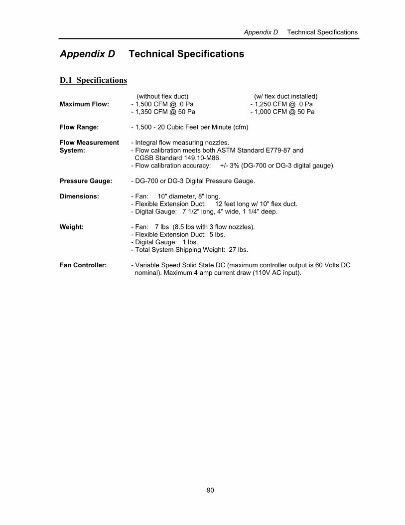
Appendix D Technical Specifications
90
Appendix D Technical Specifications
D.1 Specifications (without flex duct) (w/ flex duct installed) Maximum Flow: - 1,500 CFM @ 0 Pa - 1,250 CFM @ 0 Pa
- 1,350 CFM @ 50 Pa - 1,000 CFM @ 50 Pa
Flow Range: - 1,500 - 20 Cubic Feet per Minute (cfm)
Flow Measurement - Integral flow measuring nozzles.System: - Flow calibration meets both ASTM Standard E779-87 and
CGSB Standard 149.10-M86.- Flow calibration accuracy: +/- 3% (DG-700 or DG-3 digital gauge).
Pressure Gauge: - DG-700 or DG-3 Digital Pressure Gauge.
Dimensions: - Fan: 10" diameter, 8" long.- Flexible Extension Duct: 12 feet long w/ 10" flex duct.- Digital Gauge: 7 1/2" long, 4" wide, 1 1/4" deep.
Weight: - Fan: 7 lbs (8.5 lbs with 3 flow nozzles).- Flexible Extension Duct: 5 lbs.- Digital Gauge: 1 lbs.- Total System Shipping Weight: 27 lbs.
Fan Controller: - Variable Speed Solid State DC (maximum controller output is 60 Volts DC nominal). Maximum 4 amp current draw (110V AC input).
Appendix E Estimating HVAC System Loss From Duct Airtightness Measurements
91
Appendix E Estimating HVAC System Loss From Duct Airtightness Measurements
Appendix E contains a simple method for estimating HVAC system losses from field measurements of ductairtightness. This method uses a duct airtightness measurement along with a number of assumptions about theHVAC and duct system (including system airflow, average operating pressure in the ductwork, the breakdownof leakage between supply and return side, and the energy loss penalty from supply and return leaks) to estimatean annual energy loss for heating or cooling. The model shown below is used in the TECBLAST duct leakagetest software to estimate annual system losses.
Note: Because duct leakage loss calculations are extremely complex, this estimation technique should be usedwith caution and should be viewed only as a rough estimate of the magnitude of losses possible. The leakagerate of a duct system determined using the airtightness test procedures listed in this manual may differ from theleakage rates occurring in the duct system under actual operating conditions. In addition, the duct leakage lossestimates do not include many important but complex impacts on system efficiency including latent loadimpacts, heat pump strip heating impacts, conduction losses, increases in infiltration from dominant ductleakage, or interactions of leakage on mechanical operating efficiencies, all of which can be significantdepending on the type and location of the system being tested. We do not recommend that this simple model beused for research purposes, program design studies or impact evaluations. More sophisticated duct leakage lossmodels are available and better suited to these needs.
How to Use this Method:
The equation for this estimation procedure is located in section 5 below. Follow procedures 1-4 to determinereasonable values to use in Section 5.
1. Conduct a Duct Leakage Test
Set up your duct testing equipment to measure Duct Leakage to the Outside (in CFM). For consistency inreporting and comparison between duct systems, we recommend that you conduct your duct airtightness test at atest pressure of 25 Pa. This pressure has become the most commonly used test pressure for residential ductairtightness testing. (see Section 2 below for adjustments to the CFM25 leakage reading due to variations in ductoperating pressures). Record the CFM25 of duct leakage to the outside.
2. Determine the CFM25 Multiplier for Average Operating Pressure:
Because we tested the duct system at a test pressure of 25 Pascals, we have implicitly assumed that 25 Pascals isa representative pressure seen by the leaks in the duct system under normal operating conditions. While thisappears to be a reasonable assumption for many residential duct systems, it can be modified if you haveevidence to suggest that a different operating pressure better represents the pressure seen by the predominantduct leaks during normal operation. Table 10 below can be used to adjust the measured CFM25 for differentaverage operating pressures. This adjustment can be made separately for the supply leakage and the returnleakage in the duct system. Note: During normal operation, pressures in the duct system vary greatly, whileduring a duct leakage test, pressures are much more uniform.
For example, if the majority of leaks in the duct system are at supply boot connections, it might be reasonable toassume that the average operating pressure for the supply leaks is less than 25 Pascals (e.g. 10 or 15 Pascals). Ifthe majority of leaks are located at a high pressure location such as a supply or return plenum, then it might bereasonable to assume that the average pressure seen by the leaks is larger than 25 Pascals. Table 10 showsexample multipliers. Write down separate multipliers for the return and supply duct systems, as appropriate.
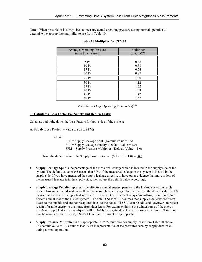
Appendix E Estimating HVAC System Loss From Duct Airtightness Measurements
92
Note: When possible, it is always best to measure actual operating pressure during normal operation todetermine the appropriate multiplier to use from Table 10.
Table 10 Multiplier for CFM25
Average Operating Pressure in the Duct System
Multiplierfor CFM25
5 Pa 0.3810 Pa 0.5815 Pa 0.7420 Pa 0.8725 Pa 1.0030 Pa 1.1235 Pa 1.2240 Pa 1.3345 Pa 1.4250 Pa 1.52
Multiplier = (Avg. Operating Pressure/25)0.60
3. Calculate a Loss Factor For Supply and Return Leaks:
Calculate and write down the Loss Factors for both sides of the system:
A. Supply Loss Factor = (SLS x SLP x SPM)
where:SLS = Supply Leakage Split (Default Value = 0.5)SLP = Supply Leakage Penalty (Default Value = 1.0)SPM = Supply Pressure Multiplier (Default Value = 1.0)
Using the default values, the Supply Loss Factor = (0.5 x 1.0 x 1.0) = 0.5
• Supply Leakage Split is the percentage of the measured leakage which is located in the supply side of thesystem. The default value of 0.5 means that 50% of the measured leakage in the system is located in thesupply side. If you have measured the supply leakage directly, or have other evidence that more or less ofthe measured leakage is in the supply side, then adjust the default value accordingly.
• Supply Leakage Penalty represents the effective annual energy penalty to the HVAC system for eachpercent loss in delivered system air flow due to supply side leakage. In other words, the default value of 1.0means that a measured supply leakage rate of 1 percent (i.e. 1 percent of system airflow) contributes to a 1percent annual loss to the HVAC system. The default SLP of 1.0 assumes that supply side leaks are directlosses to the outside and are not recaptured back to the house. The SLP can be adjusted downward to reflectregain of usable energy to the house from duct leaks. For example, during the winter some of the energylost from supply leaks in a crawlspace will probably be regained back to the house (sometimes 1/2 or moremay be regained). In this case, a SLP of less than 1.0 might be appropriate.
• Supply Pressure Multiplier is the appropriate CFM25 multiplier for supply leaks from Table 10 above. The default value of 1.0 assumes that 25 Pa is representative of the pressures seen by supply duct leaksduring normal operation.
Appendix E Estimating HVAC System Loss From Duct Airtightness Measurements
93
B. Return Loss Factor = (RLS x RLP x RPM)
where:RLS = Return Leakage Split (Default Value = 0.5)RLP = Return Leakage Penalty (Default Value = 0.5)RPM = Return Pressure Multiplier (Default Value = 1.0)
Using the default values, the Loss Factor for Return Leaks = (0.5 x 0.5 x 1.0) = 0.25
• Return Leakage Split is the percentage of the measured leakage which is located in the return side of thesystem. The default value of 0.5 means that 50% of the measured leakage in the system is located in thereturn side. If you have measured the return leakage directly, or have other evidence that more or less of themeasured leakage is in the return side, then adjust the default value accordingly. (Note: The SLS and theRLS, when added together, should always equal 1.0.)
• Return Leak Penalty represents the effective annual energy penalty to the HVAC system for each percentof return air flow that is drawn from the outside. In other words, the default value of 0.5 means that ameasured return leakage rate of 1 percent (i.e. 1 percent of system airflow) contributes to a 0.5 percentannual loss to the HVAC system. The default value of 0.5 for the RLP suggests that on average, returnleaks contribute less to energy losses than do supply leaks (default SLP of 1.0). The RLP value can beadjusted upward from the default value if you have reason to suspect that the measured return leakscontribute significantly more energy loss than “average” (e.g. pulling return air from a super heated attic), or can be adjusted downward to represent significantly less energy loss (e.g. pulling return air from amoderate temperature crawl space) .
• Return Pressure Multiplier is the appropriate CFM25 multiplier for return leaks from Table 10 above.
The default value of 1.0 assumes that 25 Pa is representative of the pressures seen by return duct leaksduring normal operation
Note: When in doubt, we recommend that you use the default values for Loss Factors.
4. Estimate the HVAC System Airflow:
Estimate the total system airflow (in CFM) from either the system nameplate, measured static pressure and fancurve, or by measuring the system airflow using a reasonable flow measuring technique (e.g. temperature risemethod, flow hood, Duct Blaster pressure matching method, or the TrueFlow Air Handler Flow Meter. Writedown the estimated/measured total system airflow.
5. Calculate Percent HVAC System Loss:
Percent HVAC System Loss =
CFM25 Leakage to Outside x (Supply Loss Factor + Return Loss Factor)
Estimated System Airflow (in CFM)
Appendix E Estimating HVAC System Loss From Duct Airtightness Measurements
94
Example 1:
We conduct a duct leakage to outside test on a 3 ton, 11 SEER heat pump system (supplies located in the atticand returns in the crawlspace). The owners report a $1,500 a year cooling bill and a $500 a year heating bill. Using 25 Pascals as our duct testing pressure, we measure 355 CFM25 of duct leakage to the outside. Wemeasure a total system airflow of 1,275 CFM using the TrueFlow Air Handler Flow Meter. We will use thedefault values for the Supply and Return Loss Factors.
Percent HVAC System Loss =
355 CFM25 x (0.5 (Supply Loss Factor) + 0.25 (Return Loss Factor))
1,275 CFM (system airflow)
= 266.3 / 1275 = .209 or 20.9%
This loss estimate (.209) can be used to estimate:
annual cooling loss: .209 x $1,500 = $314annual heating loss: .209 x $ 500 = $105annual capacity loss: .209 x 3 ton = 0.6 tonsannual operating SEER: (1 - .209) x 11 SEER = 8.7 SEER
Example 2:
For the same house used in Example 1, we separately measure the leakage in the supply and return side of theduct system and determine that the majority of the leakage (300 CFM) is in the supply side, and is located at a high pressure plenum takeoff. Because the majority of the leaks in this system are at a plenum takeoff, weassume that the average operating pressure for the supply leaks is closer to 40 Pascals, instead of 25 Pascals. For the return side of the duct system, we will use the default operating pressure of 25 Pascals.
First, we determine the CFM25 Multipliers from Table 10.
For the supply side, we will use a SPMultiplier of 1.33 (average operating pressure of 40 Pascals)
For the return side, we will use a RPMultiplier of 1.0 (default value)
Now we calculate Leakage Splits for both sides of the system:
Supply Leakage Split (SLS) = 300 CFM25 / 355 CFM25 = 0.845
Return Leakage Split (RLS) = 55 CFM25 / 355 CFM25 = 0.155
Next, we calculate the Loss Factors for both sides of the system:
Supply Loss Factor = (0.845 (SLS) x 1.0 (default SLP) x 1.33 (SPMultiplier) ) = 1.12
Return Loss Factor = (0.155 (RLS) x 0.5 (default RLP) x 1.0 (RPMultiplier)) = 0.08
Appendix E Estimating HVAC System Loss From Duct Airtightness Measurements
95
Percent HVAC System Loss =
(355 CFM25 x (1.12 (Supply Loss Factor) + 0.08 (Return Loss Factor))
1,275 CFM (system airflow)
= 426.0 / 1275 = .334 or 33.4%
This loss estimate (.334) can be used to estimate:
annual cooling loss: .334 x $1,500 = $501annual heating loss: .334 x $ 500 = $167annual capacity loss: .334 x 3 tons = 1.0 tonsannual operating SEER: (1 - .334) x 11 SEER = 7.3 SEER