Embed Size (px)
Citation preview

ROYAL ~ , I ~ - ~ ' : - : ,', ~ '~ ~ v ~ . ' i ~ : ~ , , , , , ; ~ ' , , ' ~
MINISTRY OF SUPPLY
A E R O N A U T I C A L R E S E A R C H C O U N C I L
R E P O R T S A N D M E M O R A N D A
The Development of a Variable- Mach-Number Effuser
j . B. MCGARRY
© Crown copyright I958
LONDON : HER MAJESTY'S STATIONERY OFFICE '
I958 v a z c E 5 s. 6d. ~]~'r
R. & M. No. 3097 (19,619)
A.R.O. Technical Report

The Development of a Variable Mach-Number
J. B. MCGARRY
Effuser
COMMUNICATED BY THE DtREcToR-GENsRAL o~ SCIENTIFIC RESEARCH (AIR). MINIS'tRY O~ SUPPLY
Reports MeJ orancta
4 g st, 19 5 7
No. 3 0 9 7 *
Summary.--A series of tests Was undertaken on a simple, two-dimensional, variable Mach-m.~mber effuser, or nozzle, designed for the range of supersonic flows up to I~{ach number 3.0. The performance of the nozzle was assessed from the magnitude of the percentage variation in its exit Mach-number distribution. Studies of the effect on the performance of alterations to the position of the nozzle-block pivots and other geometrical features were made.
On the basis of these studies, a final build of nozzle was developed which produced flow of a uniformity sufficient for intake and engine model testing over the Mach-number range from 1.5 to 3.0.
1. Ir~troduction.--A simple two-dimensional variable Mach-number effnser, or nozzle, to operate over the range from Mach number 1.5 to Math number 2-8 may be required for intake and enginemodel testing at high speed at the National Gas Turbine Establishment. A larger tolerance on the uniformity of Math number in the working-section is permitted than is normal in a supersonic wind tunnel.
Initially , several types of variable nozzle were considered for this use ; they were the P, exible-wall nozzle, the asymmetric sliding-block nozzle 1, the scissors-type nozzle ", the hinged-plate nozzle ~, the slotted-wall nozzle and the sliding-bump nozzle. The complexity of the control system, the liability of the plate to failure due to the malfunctioning of the system, and the limitation of the time rate of variation of Mach number detract from the usefulness of the flexible-wall nozzle. Simplicity of manufacture and control are advantages of both the sliding-block and the sliding- bump nozzles, but both entail the use of excessively long effusers, with consequent difficulties in yawing the nozzles and in allowing for boundary-layer growth. The working-section of the scissors-type nozzle is situated between the two throats, making yawing difficult, whilst the triangular working-section of the hinged-plate nozzle was considered to be disadval~tageous. Excessive suction requirements and a small w0rking-section are unsatisfactory features of the slotted-wall nozzle. No existing nozzle type being suitable for high-speed test purposes, the semi- flexible nozzle was devised by StanifortM to satisfy the requirements. This type of nozzle seemed to offer a good compromise between aerodynamic efficiency and mechanical simplicity.
Tests were therefore conducted on a model nozzle of this type, and on the same nozzle with modifications made to develop a build which would give a satisfactory flow distribution through- out the Mach-number range. The purpose of this report is to describe these tests.
* N.G.T.E. Report R.210, received 30th October, 1957.

The exit region of each version of the nozzle was designed by the Atkin method ~, which is an extension of Biisemann's method for transforming divergent radial flow into uniform parallel flow. Flow was assumed to be radial at the upstream end of the flexible plate. The nozzle was intended to cover the Mach-number range from Mach number 1.5 to Mach number 3.0, and the final design produced satisfactory uniformity of flow in the test region over this range.
2. Design Method.--The first semi-flexible nozzle was designed to embrace the required Mach- number range, according to the procedure outlined below. The errors in the flow at various Mach numbers could have been calculated by the method of characteristics but, as the labour involved was prohibitive, it was decided to obtain the results by experimental observation of the performance of a model of the nozzle.
The length of the flexible plate was calculated according to the Atkin method which has been developed to convert uniform supersonic flow at one Mach number to unifor m supersonic flow at another. This method enables the desired co-ordinates of a point on the flexible wall or beam to be determined from the parametr ic expressions:
x = r ( c o s 0 + - 0) c o s (0 + c o s e c
y = r{sin 0 + (~ -- 0) sin (0 + ~) cosec~},
where x and y represent, respectively, the co-ordinates of a point on the beam in directions parallel and perpendicular to the axis of the nozzle, ~ represents the expansion angle, # represents t h e Mach angle, and r and 0 represent the polar co-ordinates of the point, referred to the supposed source of radial flow as origin. For air flowing at normal temperatures, 0 can be expressed, from the above equations and the gas laws, as
0 ----- (6)'l~'tan -1 {(6)1/2 tan ~} -- # -}- a constant, and ~ as
r -- r~ sin #(cosec 2 ~ + 5) 3 ,
where r~ is a constant for a particular nozzle design.
By scaling to make r of unit value and y of value ½ at 0 = 0, the results of several combinations of Mach number and expansion angle were correlated. The co-ordinates of any point on the aerodynamic profile for a particular Mach number were then represented by the difference between the two values of x and the two values of y when correlated for the particular angle being considered. The important point was then that observation suggested that the application of a bending moment together with a direct force to each end of a beam of constant thickness would produce a shape similar ±o this required aerodynamic profile.
3. The Development of the Nozzle.--Preliminary tests by Carmichae] G, using a 2-in. by 2-in. model, established that flow distributions of reasonable uniformity could be obtained by using a semi-flexible nozzle. Also about this time, deLails oi a similar Swedish nozzle 7 became available. The Mach-number distributions obtained in the tests on this nozzle were more uniform, but the observations were confined to a small region in the worMng-section and to a smaller range of Mach number. In addition, details of an American nozzle 8 then came to hand, this one being designed by the method of characteristics, but being similar in many respects to the one under consideration. However, no performance figures were available.
Some minor modifications were made to the model before the detailed tests were commenced. To lessen the liability to asymmetric distributions, both nozzle blocks were linked by a gear system. Fig. 1 illustrates the construction of the nozzle and Fig. 2 is a photograph of the model in its final form. Also shown in the photograph are the inlet contraction, the outlet diffuser, and the static-pressure tube traversing gear. Details of the facilities used and the technique employed are to be found in Appendix I.
2

3.1. The I~¢itial Nozzle Design.--The nozzle was constructed with a nominal working-section of 2-in. by 2-in. The effuser consisted of uniform flexible plates, rigidly connected to nozzle blocks and constrained to lie parallel to the axis at the working-section by being clamped to slides. Variation of the nominal Math number was effected by the rotation of the nozzle blocks about the pivots by the action of a double screw-jack mechanism, actuated through gears by a single hand-wheel. All sliding surfaces were fitted with seals to prevent leakage to ehe regions behind the flexible plates.
The nozzle was designed for the range from Mach number 1.5 to Mach number 3.0, with a radius of curvature at the throat equal to twice the throat depth at the upper limiting Mach number, where a maximum expansion angle of 12 deg was adopted. Of the total nozzle length of 3} working-section heights, the flexible plate occupied 2-4 heights. An empirical allowance of 0.010 in. in depth per inch in length was made on each flexible wall to allow for boundary- layer growth throughout the nozzle, and the clamps at exit were sloped at an angle of ½ deg to the axis for the same reason.
Mach-number distributions obtained in the initial tests on this nozzle, whilst not of acceptable uniformity, were yet good enough to encourage further experimental work on the nozzle after only slight modifications, some specimen distributions being shown in Fig. 3. At low nominal Math numbers, the variation in the Mach number along the axis (axial distribution) was about ~_ 1 per cent, but this value increased to a value of ± 3 per cent at Mach number 3.0, with a peak value of ~ 4½ per cent at Mach number 2.2. As can be seen from a study of Fig. 3, the axial distributions were mostly of sinuous form. The variation of Mach number in the distributions measured normal to the axis (transverse distributions) was less than tha t in the corresponding axial distributions.
I t was suspected tha t a poor Machmumber distribution at the throat might be the cause of the unsatisfactory performance, and a temporary fairing was used in an a t tempt to improve the conditions at inlet to the nozzle. However, at the single Mach number used as a comparison, the shapes of the Maeh-number distributions were practically unchanged, so it was decided tha t further investigation would be unnecessary. The effect of the fairing on the axial Mach-number distribution is illustrated in Fig. 4a.
A slight discontinuity at the throat, simulated by a thin strip of adhesive tape, produced no noticeable effect on the performance at a single sample Mach number, although the trailing edge of the tape was sufficiently far downstream of the leading edge to obviate the possibility of the effect of leading-edge and trailing-edge neutralisation. I t was therefore concluded tha t any slight step due to faulty assembly of the flexible wall would have no significant effect on the Mach- number distribution. A comparison of the distributions obtained before and after the modification is given in Fig. 4b.
I t was then found, from a further design check, tha t the flexible plates had been attached to the nozzle blocks at a distance of 0. 070 in. upstream from the correct position. The nozzle was modified and tested in its correct form, but the distributions obtained, which are illustrated in Fig. 3, were disappointing in tha t the performance was slightly worse than tha t of the original nozzle. However, on displacing the nozzle-block pivots 0. 040 in. towards the axis, a much better performance was obtained. At this setting of the pivots, the axial variation in Mach number at Mach number 3.0 was under ~ 2 per cent, and the maximum variation was under ' ± 3 per cent. Specimen distributions recorded at this setting are also shown in Fig. 3. Further displacement of the pivots towards the axis did not improve the overall performance, although it was beneficial at some ~ a c h numbers. I t is suggested that , if the nozzle-block pivots were displaced 0-045 in. from the design condition towards the axis, the nozzle would give a satisfactory performance of about ± 1½ per cent at high and low Mach numbers but tha t at intermediate Mach numbers the variation would be as much as 4- 2½ per cent.
' 3

3.2. The First Major Moclificatiora.--Carmichael, on the basis of isolated tests, had suggested that an increase of the radius of curvature at the throat to 1{- working-section heights might improve the performance of the nozzle. The model was therefore modified to incorporate this suggestion. At its design setting the performance of the modified nozzle was better than that of the initial design but was not as good as the best previously attained. Specimen distributions are shown in Fig. 5, where it can be seen that the distributions still retained their sinuous form.
In an at tempt to improve the performance, the pivots were once more displaced towards the centre-line. Unlike the effect of this modification upon the performance of the initial nozzle, the modification to the later design resulted in a deterioration of performance. Consequently, an opposite displacement was next tried, an even larger non-uniformity being evident in the resultant distributions, as is shown in Fig. 5. Of the several pivot settings used, the original design con- ditions produced the most uniform flow, although it was not as uniform as that produced by the nozzle with high throat curvature.
At its best setting, the nozzle with low throat curvature produced a flow of which the variation in Mach number in the axial direction was ± 2 per cent at a Mach number of 3.0, decreasing to ~ 1½ per cent at a Mach number of 1.5, but with a peak of 4- 3 per cent at a Mach number of 2.5.
A comparison between the transverse Mach-number distributions measured by static wali tappings in the side wall (see Appendix I) and .those measured at the working-section by a s t a t i c probe traversing normal to the axis, led to the conclusion that the static tappings enabled the distributions to be measured as accurately as did the probe. Consequently, the use of the probe was discontinued in all later tests. Specimen distributions obtained by both methods are shown together in Fig. 6. At the high Mach numbers, the probe, when fully extended, influenced the distributions, which, therefore, are not included in the figure.
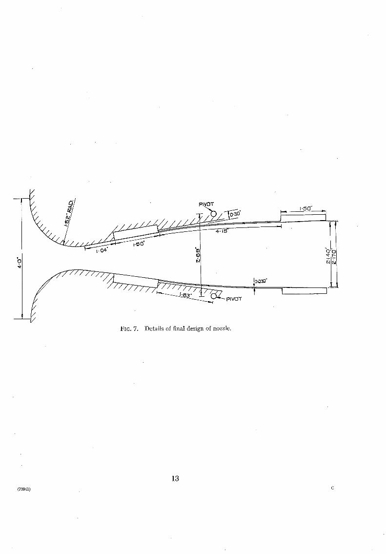
3.3. The Second Major Modificatiora.--In the previous tes)cs it was noted that the performance of the nozzles did not. deteriorate rapidly at Nach numbers slightly higher than the designed maximum. A further modification to the nozzle was therefore made in an at tempt to improve the overall performance, the dimensions being so altered as to fit a nozzle designed for a maximum Mach number of 2.5.
This new design was for a maximum expansion angle of 8 deg at Mach number 2.5, the radius of curvature at the throat being twice the minimum throat depth. Although the length of the flexible plate, namely, 2.1 working-section heights, was less than that of the first design, the total length of the nozzle was increased slightly to 4.2 heights. The cardinal dimensions of this nozzle are given in Fig. 7.
Initial tests on the modified nozzle were encouraging in that the performance was better than that with the earlier designs. The distributions are shown in Fig. 8. Both at high and low Mach numbers, the variation of Mach number was only ~ 1} per cent whilst the maximum variation was ~ 2 per cent. The major portion of this variation occurred either within the nozzle itself or at the extreme downstream end of the test rhombus. In the distance between the nozzle exit and the proposed position of the engine model intakes (see Fig. 1), and in an equal distance downstream of the intakes, the variation was, over the Mach-number range, less than ± 1 per cent. The variation in the transverse distributions (Fig. 9) was also less than ± 1 per cent except at Mach number 2.0, this exception being due, presumably, to an asymmetrical set-up of the model. Although the model intake would be situated downstream of the nozzle exit, suitable adjustment of the plenum-chamber pressure at the free jet surface would produce a parallel jet, and a uniform Mach-number distribution at exit would result in a uniform distribution at the intake section. At Mach numbers higher than 2.2, the intake would lie wholly within the Mach cone, and there would be no need to adjust the plenum pressure.
4

Alteration of t h e positions of the nozzle-block pivots failed to improve this performance, which was, however, deemed acceptable for engine model-testing requirements, although it would not be usable in most conventional wind tunnels. Specimen distributions obtained with the pivots displaced 0. 020 in. towards the centre are compared with the initial distributions in Fig. 8. The performance as designed would be acceptable at Math numbers slightly above the working range, but the test range was not extended beyond Mach number 3.0 as the material of the flexible plates was then nearing its limit of proportionality.
3.4. The Stresses in the Flexible Plales. Whilst the stresses in a flexible plate due to its enforced .curvature could have been calculated theoretically, and the stresses due to the designed static- pressure loading could have been estimated, the probable stresses induced by the pressure loading under flow-breakdown conditions when a shock wave is present in the nozzle, were unknown. A~ Series of tests on wodden representations of the nozzle under different conditions was therefore completed, the static-pressure distribution along the wall being observed on mercury manometers connected to wall static-pressure tappings. Each representation was made to represent the nozzle at one particular setting, viz., the corrected initial design set to produce flow at Mach numbers 1.5, 2.25 or 3" 0, or the nozzle after the second major modification set at Mach number 2.8. The tests on the initial nozzle design were conducted before the results of the Lests on the later nozzle, described in Section 3.3, became available.
For each of these wooden models, the position of the shock was varied by altering the pressure ratio. Influence functions for the end bending moments on the flexible plate were calculated, and when applied to the experimentally observed pressure loading these enabled the end bending moments for a particular position of the shock to be determined. By tabulat ing the resulting moments non-dimensionally as M/L2WP, where M represents the moment, L the length of the plate, W its width, and P the inlet pressure, the maximum end bending moment due to pressure loading could be obtained in a form which enabled the stress in any geometrically similar nozzle to be calculated. For example, if it were decided to test full-scale engines, it would be necessary to employ a 5-ft square nozzle with a 12-ft long steel plate, 1.5-in. thick, and the stresses to be expected at Math number 1.5 in such a plate would be 44,600 lb/in. ~ at the end near the exit, and 18,000 lb/in. ~ at the end near the throat. However, it might b e considered advisable to make an allowance for the effect of dynamic loading of the plate. In tha t event, the calculated stresses due to gas loading should be multiplied by an empirical factor of two, making the nominal design stress of the plate of such a nozzle 70,000 lb/in. ".
At the higher Mach numbers, the effect of increasing inlet total pressure outweighs the reduction in the non-dimensional end moments due to the gas loading which occurs as the Mach number of the flow is increased. The increased inlet, pressure would be necessary should the design of such a tunnel require the outlet pressure to be atmospheric. Thus, although the two worst non-dimensional end moments at Mach number 3.0 were only 0.0071 and 0. 0077, as opposed to 0-0213 and 0. 0255 at Mach number 1.5, the total stresses to be expected in a plate similar to the one mentioned in the previous paragraph were 67,700 1b/in." and 89,700 1b/in. ". It should be noted, however, tha t the latter could be reduced to 81.,000 lb/in. ~ by increasing khe thickness of the plate to its optimum value of 2 in.
A hysteresis phenomenon was observed ill the tests of the Mach-3-0representation. Over a part of the range of nozzle pressure ratio, the end moments under starting conditions did not equal those at the breakdown of flow.
As a result of these tests on the representations of the long-plate version of the nozzle, it was decided to test the short-plate representation at high Mach number only, this apparently being the critical setting. For a full-scale short-plate nozzle, which was comparable with the previously quoted example, i.e., tha t had the same working-section height, the length of the flexible plate would be only 10.4 ft, the thickness remaining unchanged at 1.5 in.
5

The results indicated that the stresses to be expected in such a plate would be 47,700 lb/in. ~ at the downstream end and 73,400 lb/in. ~ upstream. Again an increase of the thickness of the plate to the optimum of 1-8 in. would reduce these stresses slightly to 42,400 lb/in." and 71,000 lb/in. ".
As can be seen from a study of Fig. 10, in which is plotted the variation of non-dimensional end moments due to gas loading, hysteresis was also observed in the tests on the short-plate representa- tion. The peak value of the moment occurs at a pressure ratio of approximately 6.0, being then 0.0082 at the upstream end of the flexible plate. Under breakdown conditions, the direction of action of the bending moment is reversed from the direction ,during normal running. It is apparent, from the figure, that, for practically the whole range of pressure ratios, the bending moment at the end of the flexible plate near the throat exceeds that at the exit.
4. The Accuracy of Manufaclum of the Models.--It was found that the form of the Mach-number distributions was affected by the accuracy of assembly within the limits obtainable on the model. Any deviation of the pivot pins from the parallel to the transverse plane tended to produce asymmetry in the normal distribution. The pins also had to be positioned within ± 0. 001 in. of the correct distance from the axis, both with respect to the nozzle blocks and with respect to the hinge supports, before transverse distributions which were symmetrical about the centre-line were attained. A similar tolerance was placed on the longitudinal position of the pins. Indeed, errors in the positioning of these pins seemed to affect the performance of the nozzle more than any other error occasioned during the assembly of the nozzle.
In the manufacture of the nozzle, particular attention was paid to the construction o f the flexible plate. Its thickness was everywhere within 0. 0005 in. of the specified thickness of 0.030 in., and the wetted surface was flat within 0" 0005 in. The jacks were assembled with as little bacldash as possible, so that for any particular setting the nozzle blocks always returned to within 0. 001 in. of the same position. However, it was later found theoretically that the effect of a uniform taper in the thickness of the beam was of second order only.
If it were decided to test full-scale engines, the working-section of the nozzle would have to be of the order of 5-ft by 5-ft and, consequently, the tolerance on the dimensions of the flexible plate would not be unusually severe. Both the thickness and the flatness would then have to be within 0.01 in. of the specified values and the surface waviness should not exceed 0.002 in. in 3 inches in any direction .
It being inexpedient to test the proposed mechanical arrangements on a nozzle of s~ch a small scale as the 2-in. by 2-in. nozzle, a variable nozzle of working-section 1-ft by 1-ft is now being constructed. It is hoped that tests on this nozzle will also produce some information on the effects on the distributions of changes in the Reynolds number of the flow. Both the thickness and the flatness of the flexible pl/~te have to be within 0.002-in. of the nominal.
5. Extension of the Much-Number Range.--Preliminary tests on a model of a variable Mach- number nozzle designed for supersonic flows with Mach numbers less than 1.6 are described in Appendix n . Proposed variable nozzles for higher ranges of Mach number are discussed in Appendix h i .
6. Comlusiom. (a) The performance of a semi-flexible variable Much-number wind-tunnel effuser or nozzle
is considerably affected by small displacements of its nozzle-block pivots. (b) For a design Mach number of 3.0, the performance of a nozzle with high curvature at
the throat should be superior to that of a nozzle with low curvature. (c) The performance of a nozzle designed at Mach number 2.5 at its best pivot setting should
be satisfactory for intake and engine model-testing requirements at high speed. If such a nozzle were built to test full-scale engines, the material of the flexible plate at its optimum thickness might typically be designed to withstand a stress of 70,000 lb/in. ". This value is calculated assuming a dynamic loading factor of two for the variation in stress at' any sudden breakdown of the flow.
6

Acknowlec lgements . - -The au thor ,#ishes to express his indebtedness to A. D. Carmichael for his work in the pre l iminary stages of the s tudy, and to R. S tan i for th for his unfai l ing assistance and encouragement t h roughou t the investigation.
No. Author
1 H.J. Allen . . . . . .
2 A.J. Eggers and G. J. Nothwang
3 J.C. Evvard and D. D. wyatt ..
4 R. Staniforth . . . . . .
5 A.O.L. Atkin . . . . . .
6 A.D. Carmichael . . . . . .
7 J. Rosen . . . . . . . .
S W.J. 0rlin . . . . . . . .
9 P.P. Wegener and R. X. Lobb ..
R E F E R E N C E S
Title, etc.
The asymmetric adjustable supersonic nozzle for wind-tunnel application. N.A.C.A. Tech. Note 2919. March, 1953.
The Ames 10-in. by 14-in. supersonic wind tunnel. N.A.C.A. Tech. Note 3095. January, 1954.
Investigation of a variable-Mach-numbet" supersonic tunnel with non- intersecting characteristics. N.A.C.A. Research Memo. E8J13. November, 1948.
Unpublished work at N.G.T.E. October to December, 1954.
Two-dimensionai supersonic-channel design. Part I. R. & M. 2174. November, 1945.
Unpublished work at N.G.T.E. January to October, 1955.
The design and calibration of a variable-3/Iach-number nozzle. ]. Ae. Sci. Vol. 22. No. 7. July, 1955.
The semi-flexible supersonic nozzle. Presented to A.G.A.R.D. Windx Tunnel Panel. May, 1953.
An experimental study of a hypersonic wind-tunnel diffuser. J. Ae. Sci. Vol. 20. Pp. 105 to 110. 1953.
A P P E N D I X I
Facilit ies and Technique
The tests were conduc ted in a suction wind tunnel , the air being drawn from a tmosphere into the tunne l t h rough a drying plant. Af ter passing t h rough the effuser, or nozzle, via a contract ion, the working fluid entered a para l le l - throated diffuser, whence it was exhaus ted to a tmosphere . Flow was induced at low Mach numbers b y a mechanica l exhaus te r and at high Mach numbers by an ejector, bo th being s i tua ted downs t r eam from the diffuser.
Transverse Mach-number distributions, i.e., distr ibutions measured normal to the axis, at t h e ends of the flexible walls were observed on mercu ry manome te r s connected to s tat ic-pressure tappings in one of the side walls. The side wall also had a d a t u m stat ic hole drilled on the horizontal centre-l ine 1 in. ups t r eam of the vert ical statics.
Axial M a c h m u m b e r distributions, i.e., distr ibutions measured along the axis, were measured over the length of the tes t rhombus b y the use of a s tat ic probe a t t a ched to a r emote ly controlled t ravers ing gear, bo th of which are shown in Fig. 2. As the stat ic pressure at high Mach numbers was such t h a t the readings were not sufficiently accura te if measured against a tmospher ic pressure, the t raverse readings were observed as a differential pressure against the d a t u m static. At a Mach n u m b e r of 3.0, wi th a tmospher ic inlet conditions, an error of 0.020 in. of m e r c u r y is equivalent to a Mach-number error of 0- 017. Consequently, the differential pressure was measu red in Tetral in, a low-vapour-pressure o i l
7

The static probe comprised a cone, having a 5 deg semi-angle and the base of which was 1 mm in diameter, attached to a length of l-ram hypodermic tubing in which four 0" 010-in. diameter static holes were drilled 10ram downstream of the base of the cone. This tubing was attached to a length of 3-ram diameter tubing and supported in a centralising spider downstream of the .working-section. The large-diameter tubing was attached to the traversing gear through a slot m the side wall of the diffuser, which was sealed by a length of steel shim.
The performance of any particular design of nozzle was assessed from the magnitude of the variation in the Mach-number distribution over a test rhombus formed by lines drawn from the downstream ends of the flexible walls at the particular Mach angle of the flow. Both ~cransverse and axial distributions were thus measured, and the variation of Mach number from the mean was consideredas the criterion for the assessment of performance. The distributions were recorded at various nominal Mach numbers in the working range,'variation of Mach number being effected by the action of the screw-jack mechanism.
All the transversely arranged static tappings and the datum static were connected to a mercury manometer board. A U-tube containing Tetralin as a manometric fluid was connected between the datum static and the traversing probe, the U-tube being by-passed during the starting and the stopping of the tunnel in order to avoid blowing the oil out of the U-tube when there was a shock between the probe and the datum static.
APPENDIX II
The Design of a~ Effuser for the Range up to Mach Number 1.6
Since it was decided to extend the investigations to the study of the performance of an effuser, or nozzle, suitable for flows up to Mach number 1.6, a model was made with an expansion angle of 5 deg at this maximum Mach number. The radius of curvature at the throat was again 1½ times the working-section height but the total length of the nozzle was reduced to 3 working- section heights, mainly because of the reduction in length of the flexible plate to 1.1 heights.
Axial Mach-number distributions were recorded for flows from Mach 1.0 to Mach 1.6, the design Mach number, whilst the range of transverse distributions was extended to cover high subsonic flows. As the performance was poor, the pivots were again displaced symmetrically towards the tunnel centre-line. The performance of this nozzle cannot be compared directly with that of the higher speed designs, but close similarity is evident in some respects. The general form of the axial Maeh-number distributions was similar, and the magnitude of the variation was once more greatest in the middle of the Mach-number range. Specimen distribution curves are plotted in Fig. 11.
Displacement of the position of the nozzle-block pivots was once more effective, the best overall • performance being observed with the pivots displaced 0. 030 in. towards the centre-line. At this setting, the magnitude of the axial variation was 4- 1½ per cent at the maximum test Mach number, 4- 2{- per cent at Maeh number 1- 4, and 4- 1} per cent at Mach number 1.1. Through- out the whole range, the transverse variation of the Maeh number did not exceed 4- 12 per cent.
Whilst this performance is not up to the standard of the nozzle designed for higher Mach numbers, it should be possible to improve the uniformity of distribution by modification of the curvature at the throat.
8

A P P E N D I X III
Extension of the Mach-Number Range
An extension of the Mach-number range entails a reconsideration of the choice of variable- nozzle types. In a nozzle designed to cover the range of Mach number from 3-0 to 5.0, each nozzle block would have to move towards the centre-lille a distance of less than 1/10 of the working-section height. If a semi-flexible nozzle were to be employed for this range its angular rotation would thus be very small, and it was thought that the effect of changing plate curvature might be negligible, that is, that the Mach-number distribution from a nozzle comprising only nozzle blocks capable of rotation about their downstream ends might be sufficiently uniform. Consequently, some graphical checks were completed to test the accuracy of this supposition, and it was found that the error really does appear to be small. Tests will therefore be made on a nozzle of this type in the near future.
At even higher Mach numbers, in the region of Mach number 5.0 to Mach number 7.0, it has already been shown 9 that good performances have been attained by the use of a straight-line effuser. To change the flow from Mach number 5.0 to Mach number 7.0, each nozzle block need only move in a distance of 0.015 of the working-section height, this amount hardly affecting the configuration of a flexible plate, which could once more be omitted.
9 (73941) B

~ $1TION
~ENGINE M O D E L - -
FIG. 1. Half-section of 2-in. model nozzle.
e
FIG. 2. Photograph of 2-in. model nozzle.
10

¢) 0
o I X < Z
- ~ ° "'o,, , " - ~ . . ~ ~ , .a
-- ¢z:
'~ . ~ , ~ . ~
i~n iv o
o~
/
~ g l N F I N H3~'I,N
,n 9 j
~-~ o IN X Z
', ~ _ J
c~
~. F- o
.3 z
0
"o "~NVna ~.~-xna "~nZZON 6 ~_ ®
\ ~ch
~- / fill.
~b u-
1:3 h
Z I .X ~ . . i / /
I f
:i ̧j- l.X I I
\~ ', I ~Ng-ld .I.'~'IJrlO "~'IZZON
\ i k).\ o~ / i i
• )
F-
0
, i!) - 8 z ! )/ ~-°
l l f
'X , U I 0
i~ n n
rv Ill
I]l P
/ / t '/ I
I q I o
I Z , ' / j ~ f ~ a
! I I
._1
O3 O
~l-q g IA,II"I p,.I HDVIAI
El
11
0
q~ ~D
c~
0
CO
©

IV
Z z-z
U < 2
LIMIT5 OF TEST RHOMBUS L IMIT~ OF T E S T I~HOMBLIS ~ / \
-I.- ..... --~ ",, /: ~.~ \ , ~ \ I ,,,/
l ; - - > ! . . . . . . . I " : - " - - INITIAl,, DE:51GNI I _/ " -
. . . . . . PIVOT8 D I 6 P L A C E D 0 " 0 8 0 iN. TOWAR05 AY, I~/ 2~.4 -" . - - - P I V O T S DI6PLACED 0 . 0 4 0 IN.AWAY ~'I~OM ~/XI~,
i .8
1.8
1.4
g
H
Z
3"0 ?--0 l'O 0.0 I.O 2"0
UPSTREAM ~WNS'rREAM TRAVE!~$E PI361TInN RELATIVE. TO N O Z Z L E EXIT (INS)
FIG. 5. P e r f o r m a n c e a f t e r f i r s t m o d i f i c a t i o n .
3.13
hi In 2 -]
2
T U <
_ _ WALL T A P P I N G 5
.... PROBE
i
b4 /
?-'0
1"8
I-6
1-4 1.0 0-~ 0.0 }.5 ItO
T R A V E R S E POSITION RELATIVE: T O C E N T R E - - L I N E INS. )
FIG. 6. Comparison between dis t r ibut ions obtained by probe and b y wall tappings.
' PIVOT /
o
= ~ I V O T
FIG. 7. Details of final design of nozzle.
I 0,030"
1"50" i - - I - -
J J - - i
J
13 (73941) C

Z
OF" T E S T ~ H O M B U ~ L I M I T S OF" "rE~T %
• INI71AL DI . 'S lGN
I (J <
1"8
1'6
3"0 2 '0 I ' 0 O-O I '0 2"0 3"0
U P S T R E A M D O W N S T R E A M E x I T { i T I IRAVEI~gE POSITION I ~ E L A T I V E TO N O Z Z L E \ 1 1 ~
FIG. 8. Performance of final nozzle. Axial distribution.
,~ '0
D 8
2"(
fV I,I m
3 ~'0 7
T U
/ 1
1.8
1"6
1,4
INITIAL- D E S I G N ] - - - - - P I V O T S D I S P L A C E D 0 ' 0 2 0 IM.
1,0 0 , 5 0 , 0 0 . 5 1.o T R A V E t ~ E POSITION I ~ E L A T I V E T O CF'NTI~ ~' - L I N E ( INS 1
FIG. 9. Performance of final nozzle. Transverse distribution.

H
#
;.,a
.oo
¢,n
n
<
I"1 < CI
J
¢1 <
o I,I :3 n
I- ,,z
0 Z
Z Ld m
J
Z 13 I/3 Z hi
D 1:3
1',"1
6
I L.
2
I
O.I
I I / I
I
FIG. 10.
/
.+%~ >,,~ i ,
>~/._'0; \ t I ~, 0~; $_@~ ,,,, I/--A v O'~
4!,, il,,'qT--.< o ~ : i"\. '/ ' ' I .~G , I i
M, MOMENT AT .ENID .NEAR EXIT Ma MOMENT AT E N D NEAR TIqROAT' PdPi NOZZLE P2ESSUR~ RATI(
)-~ 0.3 0-4 0"5 0"~
REC ~ R O C A L OF N O Z Z L E PRESSURE RATIO
Variation of non-dimensional end bending moments with nozzle pressure ratio.
z
¢J
1.5
1.4
I.I
i /
f ~
f t \ /
f \ ,.,,/~\. i ,~ ~ ~~
/ /
i . , , . . ~ /
/ /
i i "
/ /
" i l l ' l
I'Z 0'8 UP~T~F'AM
TRAUE2$E P051TION
/ l- tJ
- - I N I T I A L D~'S~N :3 ----PIVOT6 DISPLACED Q'030 l= l
K I
N o~ 2
0'4 0.0 0"4 0'8 DOWNST~
gELATIV Ir TO NOZZLC EXIT ( INS)
FIG. 11.
IN
1,2
Performance of nozzle designed at Mach I. 6.

R. & M. No. 30
"1
Publications of the Aeronautical Research Council
A N N U A L T E C H N I C A L R E P O R T S O F T H E A E R O N A U T I C A L R E S E A R C H C O U N C I L ( B O U N D V O L U M E S )
1939 Vol. I. Aerodynamics General, Performance, Airscrews, Engines. 5os. (52s.). Vol. II. Stability and Control, Flutter and Vibration, Instruments, Structures, Seaplanes, etc.
63s. (65s.)
I94o Aero and Hydrodynamics, Aerofoils, Airscrews, Engines, Flutter, Icing, Stability and Control, Structures, and a miscellaneous section. 5os. (52s.)
I941 Aero and Hydrodynamics, Aerofoils, Airscrews, Engines, Flutter, Stability and Control, Structures. 63s. (65s.)
1942 Vol. I. Aero and Hydrodynamics, Aerofoils, Airscrews, Engines. 75 s. (77s.) Vol. II. Noise, Parachutes, Stability and Control, Structures, Vibration, Wind Tunnels.
47s. 6d. (49 s. 6d.) 1943 Vol. I. Aerodynamics, Aerofoils, Airscrews. 80s. (82s.)
Vol. IL Engines, Flutter, Materials, Parachutes, Performance, Stability and Control, Structures. 9os. (92s. 9d.)
1944 Vol. I. Aero and Hydrodynamics, Aerofoils, Aircraft, Airserews, Controls. 84s. 186s. 6d.) Vot. IL Flutter and Vibration, Materials, Miscellaneous, Navigation, Parachutes, Performance,
Plates and Panels, Stability, Structures, Test Equipment, Wind Tunnels. 84s. (86s. 6d.)
1945 Vol. I. Aero and Hydrodynamics, Aerofoils. I3OS. (I32S. 9d.) Vol. IL Aircraft, Airscrews, Controls. I3OS. (I32S. 9d.) Vol. III. Flutter and Vibration, Instruments, Miscellaneous, Parachutes, Plates and Panels,
Propulsion. I3OS. (I32S. 6d.) VoI. IV. Stability, Structures, Wind Tunne/s, Wind Tunnel Technique. 13os. (I 3 zs. 6d.)
Annual Reports of the Aeronautical Research Council-- 1937 2s. (2s. 2d.) 1938 zs. 6d. (is. 8d.) 1939-48 3 s. (3 s. 5d.)
Index to all Reports and Memoranda published in the Annual Technical Reports, and separately I
April, 195o - R. & M. 2600 2s. 6d. (2s. lOg.)
Author Index to all Reports and Memoranda of the Aeronautical Research Council--
19o9--January, 1954
Indexes to the Technical Reports Council--
December 1, I936---June 3 o, 1939 July I, I939--June 3 o, 1945 July I, I945--June 30, 1946 July I, I946--December 31, 1946 January I, I947--June 3% 1947
Published Reports and Memoranda Counci l - -
Between Nos. 225 I-2349 Between Nos. 2351-2449 Between Nos. 2451-2549 Between Nos. 2551-2649
R. & M. No. 257o 15s. (iSs. 8d.)
of the Aeronautical Research
R. & M. No. 185o IS. 3 d. (IS. 5d.) R. & M. No. 195o is. (IS. 2d.) R. & M. No. 2050 is. (is. 2,/.) R. & M. No. 215o IS. 3,/. (is. 5d.) R. & M. No. 2250 is. 3 d. (is. 5d.)
of the Aeronautical Research
R. & M. No. 2350 xs. 9 d. (IS. IId.) R. & M. No. 245o 2s. (2s. 2d.) R. & M. No. 2550 2s. 6d. (2s. 1or.) R. & M. No. 265o 2s. 6d. (2s. lod.)
Between Nos. 265r-2749 R. & M. No. 275 ° 2s. 6d. (2s. xod.)
Prices in brackets include postage
HER MAJESTY'S STATIONERY OFFICE York House, Kingsway, London W.C.z; 423 Oxford Street, London W.I; I3a Castle Street, Edinburgh 2; 39 King Street, Manchester 2 ~ z Edmund Street, Birmingham 3 ; I°9 St. Mary Street, Cardiff; Tower Lane, Bristol t
80 Chichester Street, Belfast, or through any bookseller.
S.O. Code No. 23-3097
R. & M. No. 30


![NERC Highlights and Minutes/…Translate this page%PDF-1.6 %âãÏÓ 3097 0 obj > endobj 3244 0 obj >/Filter/FlateDecode/ID[2F1A588DB79AEB418C2D243467788082>]/Index[3097 8299]/Info](https://img.pdfslide.us/doc/110x75/5ace74357f8b9ac1478bb6be/highlights-and-minutestranslate-this-pagepdf-16-3097-0-obj-endobj-3244-0.jpg)