Embed Size (px)
Citation preview
Maintenance Handbook for U/S Compressor March’2003
GOVERNMENT OF INDIA MINISTRY OF RAILWAYS
(For Official Use Only)
dEizs’kjksa ds vuqj{k.k dh y?kqiqfLrdkdEizs’kjksa ds vuqj{k.k dh y?kqiqfLrdkdEizs’kjksa ds vuqj{k.k dh y?kqiqfLrdkdEizs’kjksa ds vuqj{k.k dh y?kqiqfLrdk (vaMjLyax ,lh dkspksa ds fy,)
MAINTENANCE HANDBOOK ON
COMPRESSORS (Of Under slung AC Coaches)
Centre for Advanced Maintenance TECHnology
Excellence in Maintenance
Maharajpur, GWALIOR - 474 020
CAMTECH/E/2003/ACComp/1.0 dseVsd\bZ\2003\,lh dEi\1-0
March, 2003 EkkpZ,2003
CAMTECH/2003/E/ACCOMP/1.0
Maintenance Handbook for U/S Compressor March, 2003
2
dEizs’kjksa ds vuqj{k.k dh y?kqiqfLrdkdEizs’kjksa ds vuqj{k.k dh y?kqiqfLrdkdEizs’kjksa ds vuqj{k.k dh y?kqiqfLrdkdEizs’kjksa ds vuqj{k.k dh y?kqiqfLrdk (vaMjLyax ,lh dkspksa ds fy,)
MAINTENANCE HANDBOOK
ON
COMPRESSORS (Of Under Slung AC Coaches)
CAMTECH/2003/E/ACCOMP/1.0
Maintenance Handbook for U/S Compressor March, 2003
3
FOREWORD
Compressor being heart of Air Conditioning System, its
proper working is necessary to ensure reliability of air-conditioning system in passenger coaches. CAMTECH has prepared this handbook on maintenance of these Compressors. It covers all aspects of maintenance, trouble shooting, important instructions and tools required for their maintenance. I hope the field staff will find this book useful. CAMTECH, Gwalior C. B. MIDDHA
Date: 20th March, 2003 Executive Director
CAMTECH/2003/E/ACCOMP/1.0
Maintenance Handbook for U/S Compressor March, 2003
4
PREFACE
The proper upkeep of Compressor is necessary to ensure proper working of AC coaches. This handbook on Maintenance of Compressors for underslung AC coaches has been prepared by CAMTECH with the objective of making our maintenance personnel aware of correct maintenance and overhaul techniques to be adopted in the field.
It is clarified that this handbook does not supersede any existing provisions laid down by RDSO or Railway Board and it is not a statutory document.
I am sincerely thankful to all officers and staff of PS & EMU directorate of RDSO/ LKO for their valuable suggestions and comments. I am thankful to Shri Rambir Singh Sikarwar Sr.CTA/Elect. and Smt. Sangeeta Shrivastava / DEO who brought the handbook in this form. I am also thankful to all field personnel who helped us in preparing this handbook. Technological upgradation and learning is a continuous process. Hence feel free to write to us for any addition/ modification in this handbook. We shall highly appreciate your contribution in this direction.
CAMTECH, Gwalior RANDHAWA SUHAG Dated :17th March, 2003 Director/Elect
CAMTECH/2003/E/ACCOMP/1.0
Maintenance Handbook for U/S Compressor March, 2003
5
Chapter Description Page No.
No.
Foreword v
Preface vii
Contents ix
Correction Slip xi 1. GENERAL 1
2. MAINTENANCE 13
3. TROUBLE SHOOTING 20
4. IMPORTANT INSTRUCTIONS 28 FOR MAINTENANCE
APPENDIX - I 30
List of recommended tools
APPENDIX - II 32
List of Modification sheets & SMIs issued by RDSO
REFERENCES 33
CONTENTS
CAMTECH/2003/E/ACCOMP/1.0
Maintenance Handbook for U/S Compressor March, 2003
6
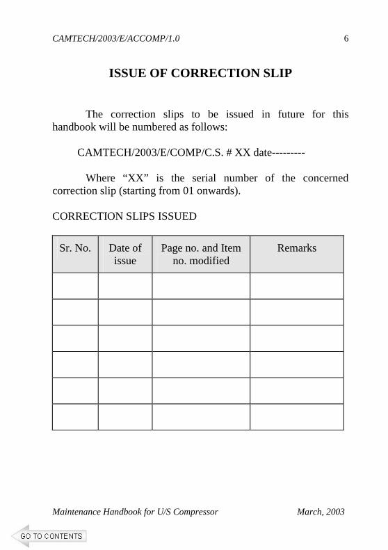
ISSUE OF CORRECTION SLIP
The correction slips to be issued in future for this handbook will be numbered as follows: CAMTECH/2003/E/COMP/C.S. # XX date--------- Where “XX” is the serial number of the concerned correction slip (starting from 01 onwards). CORRECTION SLIPS ISSUED
Sr. No. Date of issue
Page no. and Item no. modified
Remarks
Maintenance Handbook for U/S Compressor March’2003
CHAPTER 1
GENERAL
1.1 With the improvement in standard of living in our country, the average passenger's requirement for comfort have been going up steadily. To meet the demand of long journey passengers for greater comfort inside the coach, Air-conditioning of coaches is necessary. Demand of AC coaches is increasing day-by-day.
It is necessary to keep the air-conditioning coaches
in proper working condition. Failure en-route of AC coaches results into financial loss to Railways and invites public criticism. Therefore the staff should be fully aware for maintenance requirement of AC equipment in order to ensure reliable performance.
1.2 Compressor is heart of refrigeration system. Refrigeration
is produced by allowing a liquid refrigerant from high pressure vessel to pass and boil in a coil or evaporator. The latent heat needed for the boiling is taken from the surrounding space of the evaporator, thereby cooling the space. After passing from the evaporator the refrigerant is reclaimed with the help of compressor.
CAMTECH/2003/E/ACCOMP/1.0
Maintenance Handbook for U/S Compressor March, 2003
2
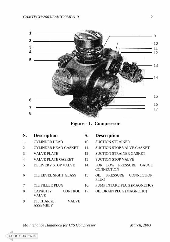
Figure - 1. Compressor
S. Description S. Description 1. CYLINDER HEAD 10. SUCTION STRAINER
2 CYLINDER HEAD GASKET 11. SUCTION STOP VALVE GASKET
3 VALVE PLATE 12 SUCTION STRAINER GASKET
4 VALVE PLATE GASKET 13 SUCTION STOP VALVE
5 DELIVERY STOP VALVE 14. FOR LOW PRESSURE GAUGE CONNECTION
6 OIL LEVEL SIGHT GLASS 15 OIL PRESSURE CONNECTION PLUG
7 OIL FILLER PLUG 16. PUMP INTAKE PLUG (MAGNETIC)
8 CAPACITY CONTROL VALVE
17. OIL DRAIN PLUG (MAGNETIC)
9 DISCHARGE VALVE ASSEMBLY
9
10 11 12
13
14 15
16 17
1
2
3 4
5
6
7
8
CAMTECH/2003/E/ACCOMP/1.0
Maintenance Handbook for U/S Compressor March, 2003
3
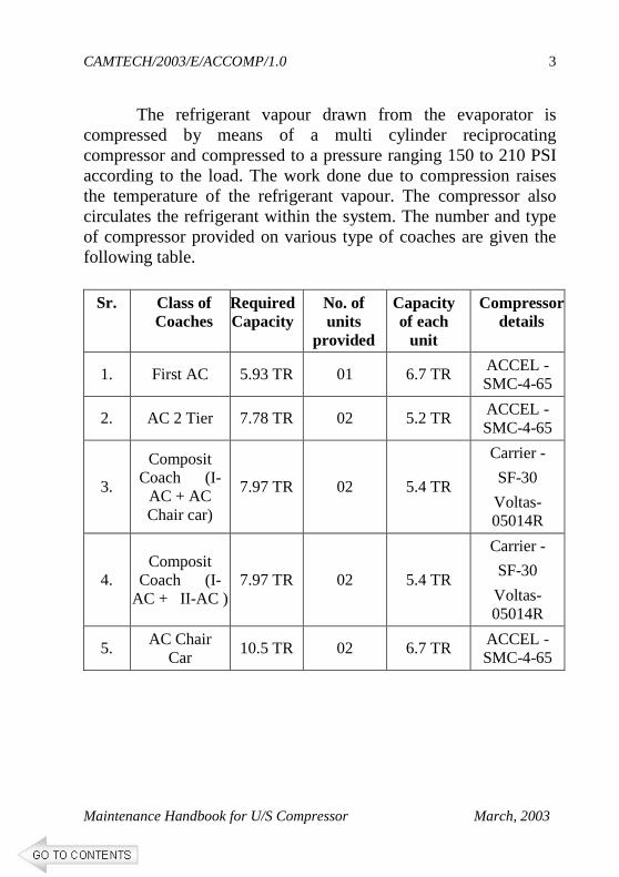
The refrigerant vapour drawn from the evaporator is compressed by means of a multi cylinder reciprocating compressor and compressed to a pressure ranging 150 to 210 PSI according to the load. The work done due to compression raises the temperature of the refrigerant vapour. The compressor also circulates the refrigerant within the system. The number and type of compressor provided on various type of coaches are given the following table.
Sr. Class of Coaches
Required Capacity
No. of units
provided
Capacity of each
unit
Compressor details
1. First AC 5.93 TR 01 6.7 TR ACCEL -SMC-4-65
2. AC 2 Tier 7.78 TR 02 5.2 TR ACCEL -SMC-4-65
3.
Composit Coach (I-
AC + AC Chair car)
7.97 TR 02 5.4 TR
Carrier -
SF-30
Voltas- 05014R
4. Composit
Coach (I-AC + II-AC )
7.97 TR 02 5.4 TR
Carrier -
SF-30
Voltas- 05014R
5. AC Chair Car
10.5 TR 02 6.7 TR ACCEL -SMC-4-65
CAMTECH/2003/E/ACCOMP/1.0
Maintenance Handbook for U/S Compressor March, 2003
4
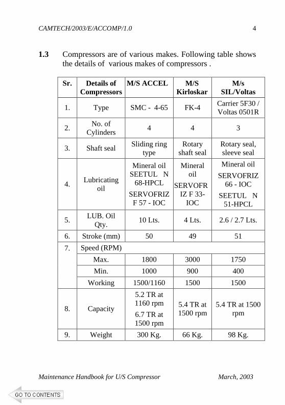
1.3 Compressors are of various makes. Following table shows the details of various makes of compressors .
Sr. Details of Compressors
M/S ACCEL M/S Kirloskar
M/s SIL/Voltas
1. Type SMC - 4-65 FK-4 Carrier 5F30 / Voltas 0501R
2. No. of Cylinders
4 4 3
3. Shaft seal Sliding ring type
Rotary shaft seal
Rotary seal, sleeve seal
4. Lubricating
oil
Mineral oil SEETUL N
68-HPCL
SERVOFRIZ F 57 - IOC
Mineral oil
SERVOFRIZ F 33-
IOC
Mineral oil
SERVOFRIZ 66 - IOC
SEETUL N 51-HPCL
5. LUB. Oil Qty.
10 Lts. 4 Lts. 2.6 / 2.7 Lts.
6. Stroke (mm) 50 49 51
Speed (RPM)
Max. 1800 3000 1750
Min. 1000 900 400
7.
Working 1500/1160 1500 1500
8. Capacity
5.2 TR at 1160 rpm
6.7 TR at 1500 rpm
5.4 TR at 1500 rpm
5.4 TR at 1500 rpm
9. Weight 300 Kg. 66 Kg. 98 Kg.
CAMTECH/2003/E/ACCOMP/1.0
Maintenance Handbook for U/S Compressor March, 2003
5
1.4 CONSTRUCTION
Compressors are provided with an automatic capacity control device, which varies the capacity of the compressor according to the variation of refrigeration load requirements and also allows the compressor to start partially unloaded.
The compressor has following Technical
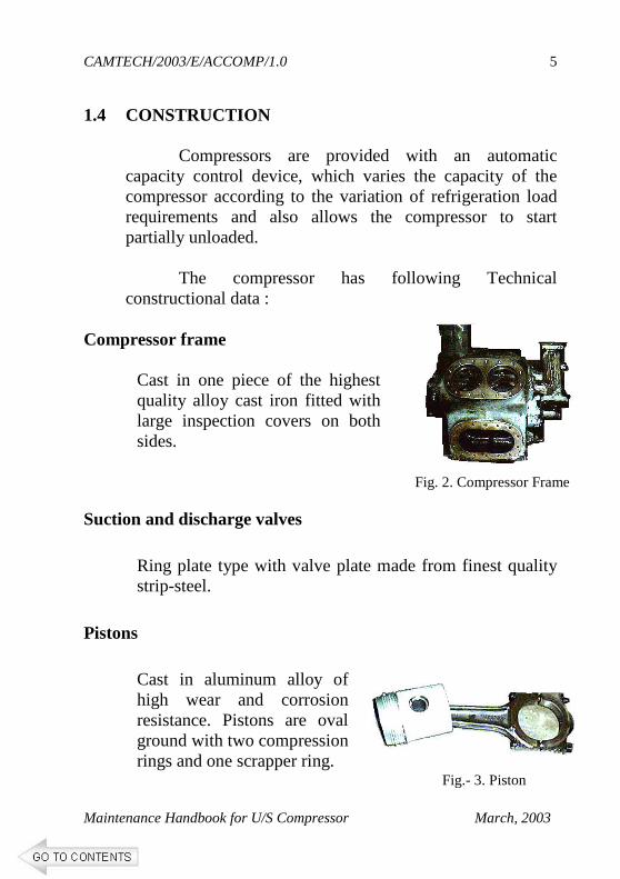
constructional data : Compressor frame
Cast in one piece of the highest quality alloy cast iron fitted with large inspection covers on both sides.
Suction and discharge valves
Ring plate type with valve plate made from finest quality strip-steel.
Pistons
Cast in aluminum alloy of high wear and corrosion resistance. Pistons are oval ground with two compression rings and one scrapper ring.
Fig. 2. Compressor Frame
Fig.- 3. Piston
CAMTECH/2003/E/ACCOMP/1.0
Maintenance Handbook for U/S Compressor March, 2003
6
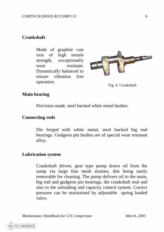
Crankshaft
Made of graphite cast iron of high tensile strength, exceptionally wear resistant. Dynamically balanced to ensure vibration free operation.
Main bearing
Precision made, steel backed white metal bushes. Connecting rods
Die forged with white metal, steel backed big end bearings. Gudgeon pin bushes are of special wear resistant alloy.
Lubrication system
Crankshaft driven, gear type pump draws oil from the sump via large fine mesh strainer, this being easily removable for cleaning. The pump delivers oil to the main, big end and gudgeon pin bearings, the crankshaft seal and also to the unloading and capacity control system. Correct pressure can be maintained by adjustable spring loaded valve.
Fig. 4. Crankshaft
CAMTECH/2003/E/ACCOMP/1.0
Maintenance Handbook for U/S Compressor March, 2003
7
Shaft Seal - Sliding ring type
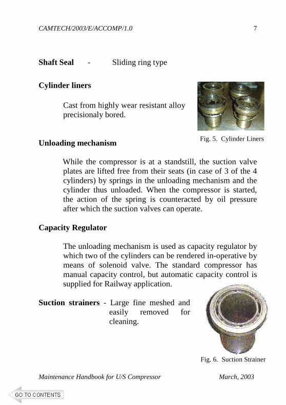
Cylinder liners
Cast from highly wear resistant alloy precisionaly bored.
Unloading mechanism
While the compressor is at a standstill, the suction valve plates are lifted free from their seats (in case of 3 of the 4 cylinders) by springs in the unloading mechanism and the cylinder thus unloaded. When the compressor is started, the action of the spring is counteracted by oil pressure after which the suction valves can operate.
Capacity Regulator
The unloading mechanism is used as capacity regulator by which two of the cylinders can be rendered in-operative by means of solenoid valve. The standard compressor has manual capacity control, but automatic capacity control is supplied for Railway application.
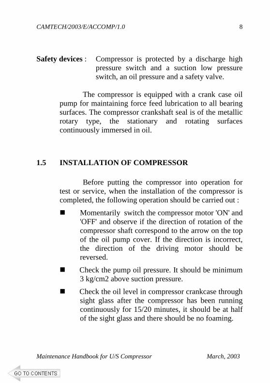
Suction strainers - Large fine meshed and
easily removed for cleaning.
Fig. 5. Cylinder Liners
Fig. 6. Suction Strainer
CAMTECH/2003/E/ACCOMP/1.0
Maintenance Handbook for U/S Compressor March, 2003
8
Safety devices : Compressor is protected by a discharge high
pressure switch and a suction low pressure switch, an oil pressure and a safety valve.
The compressor is equipped with a crank case oil
pump for maintaining force feed lubrication to all bearing surfaces. The compressor crankshaft seal is of the metallic rotary type, the stationary and rotating surfaces continuously immersed in oil.
1.5 INSTALLATION OF COMPRESSOR
Before putting the compressor into operation for test or service, when the installation of the compressor is completed, the following operation should be carried out :
� Momentarily switch the compressor motor 'ON' and 'OFF' and observe if the direction of rotation of the compressor shaft correspond to the arrow on the top of the oil pump cover. If the direction is incorrect, the direction of the driving motor should be reversed.
� Check the pump oil pressure. It should be minimum 3 kg/cm2 above suction pressure.
� Check the oil level in compressor crankcase through sight glass after the compressor has been running continuously for 15/20 minutes, it should be at half of the sight glass and there should be no foaming.
CAMTECH/2003/E/ACCOMP/1.0
Maintenance Handbook for U/S Compressor March, 2003
9
� Starting the compressor : When assembly of the compressor is completed, before the compressor is started for pressure test, evacuation or refrigeration, the operator must make the following checks :
� That, the compressor is charged with a suitable grade oil with sufficient quantity.
� That, it is possible to rotate the compressor easily by hand.
� That, the compressor is rotating in the direction indicated by the arrow on the end cover of oil pump.
� That, the high pressure cutout is properly connected and adjusted.
� That, the oil pressure control is adjusted to switch off and thus stop the compressor at 2 kg per sq cm oil pressure. ( The normal oil pressure should be approx 3 kg per sq cm)
� That, the compressor and its motor is properly mounted on the base frame.
CAMTECH/2003/E/ACCOMP/1.0
Maintenance Handbook for U/S Compressor March, 2003
10
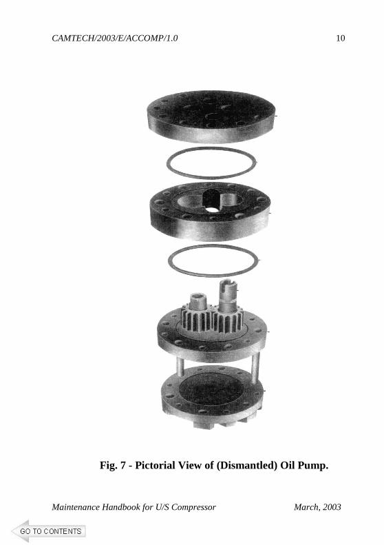
Fig. 7 - Pictorial View of (Dismantled) Oil Pump.
CAMTECH/2003/E/ACCOMP/1.0
Maintenance Handbook for U/S Compressor March, 2003
11
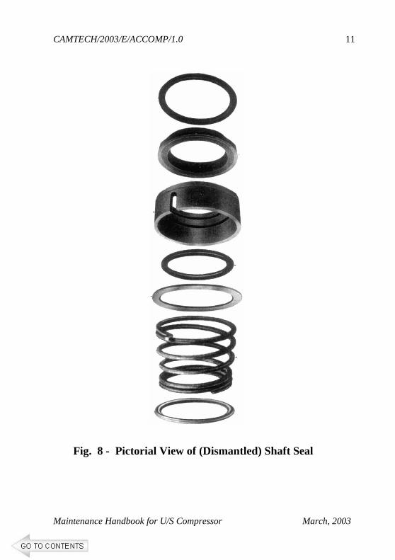
Fig. 8 - Pictorial View of (Dismantled) Shaft Seal
CAMTECH/2003/E/ACCOMP/1.0
Maintenance Handbook for U/S Compressor March, 2003
12
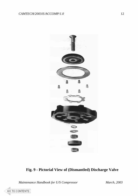
Fig. 9 - Pictorial View of (Dismantled) Discharge Valve
CAMTECH/2003/E/ACCOMP/1.0
Maintenance Handbook for U/S Compressor March, 2003
13
CHAPTER 2
MAINTENANCE
2.1 TRIP SCHEDULE
■ Check the logbook remarks at coach arrival.
■ Check the proper lubrication of compressor level of oil when operating. It should be upto half of the bull eye glass.
■ Lubricate the compressor as per RDSO SMI No.
RDSO/AC/SMI/6. (Note :- Do not re-use the oil removed from the
compressor.)
■ Examine the reading of HP, LP and OP gauges recorded during the journey for abnormality and take necessary action. ( LP = 2.6 to 2.8 kg per sq cm, OP= 80 PSI, HP = 11 Kg per sq. cm)
■ Examine flexible tyre coupling and replace, if found
defective.
■ Clean the compressor externally with compressed air.
CAMTECH/2003/E/ACCOMP/1.0
Maintenance Handbook for U/S Compressor March, 2003
14
■ Check for signs of leakage at joints & shaft seal and take remedial measure wherever necessary.
■ Examine the fixing arrangement, check the
condition of the anti vibration mountings for tightness of the fixing bolt and replace if required.
■ Finally record the readings of LP, HP & OP.
2.2 MONTHLY SCHEDULE
In addition to the items of trip do the following
■ Check tightness of bolts of anti-vibration mounting with 30 kg- m torque and tighten if necessary.
■ Check the tightness of nuts and bolts of compressor
head and its cover.
■ Check oil and liquid levels and note any signs of leakage which will be indicated by presence of the oil at the point of leakage.
■ Clean the oil strainer with petrol or CTC (Carbon
Tetrachloride).
CAMTECH/2003/E/ACCOMP/1.0
Maintenance Handbook for U/S Compressor March, 2003
15
2.3 SIX MONTHLY SCHEDULE (IOH) In addition to the items of trip & monthly schedule do the
following.
■ Clean the suction strainer with petrol or CTC
(Carbon Tetrachloride).
■ Top up the oil.
■ Check proper working of capacity control solenoid
valve.
■ Check and Replace the defective/worn out gasket.
2.4 PERIODIC OVER-HAULING (POH) The given activities are only for under slung type
AC system installed with open type compressors. Remove driving flange and provide `V' groove pulley. Test the compressor to ascertain its condition. Record the oil pressure during run. For Carrier and ACCEL compressors, oil pressure developed should be 3.2 to 3.9 Kg/Sq. cm and 4.2 to 4.9 Kg/sq.cm respectively.
A. Maintenance activities on Compressor
■ Dismantle the compressor completely. ■ Inspect and check the dimensions of the
wearing components. Replace the worn out components.
CAMTECH/2003/E/ACCOMP/1.0
Maintenance Handbook for U/S Compressor March, 2003
16
■ Replace following components 100% irrespective of their condition.
■ Piston rings ■ Scrapper ring ■ Suction and discharge valve ■ Shaft seal assembly/O rings ■ Gasket packing ■ Half section bearing ■ Self locking nuts ■ Lubricating oil of correct grade.
■ Replace other components on condition basis.
The sealed control valve shall be replaced after ascertaining its performance.
■ Assemble the compressor with replaced
components and charge it with suitable grade lubricating oil. Change the lube oil and refrigerant suction strainers.
■ In case of carrier 5F 30 compressor match the
colour to ensure proper matching between tapered shaft and corresponding flexible coupling.
■ In case of ACCEL compressor check the end
play of crank shaft and replace the thrust plate, if necessary.
■ Check the anti vibration mounting and replace,
if necessary on condition basis.
CAMTECH/2003/E/ACCOMP/1.0
Maintenance Handbook for U/S Compressor March, 2003
17
■ Lubricate the compressor as per RDSO SMI No.RDSO/AC/SMI/6.
■ Remove the excess oil from the compressor.
■ Tighten nut, bolts & fastners properly.
■ Follow RDSO SMI No. RDSO/AC/SMI/10
circulated vide their letter no. EL/7.1.83/J9 dated 20.09.1999 to prevent gas leakage from shaft seal.
B. Tests on Overhauled Compressor
Following tests should be conducted on overhauled compressor
■ Temperature rise test
■ Volumetric efficiency test
■ Leak back test
■ Vacuum test
■ Sub merge test
i. Temperature rise test This test shall be conducted with compressor
running in free air with both suction and discharge valve open. Run the compressor till the temperature gets stabilized. The temperature will be recorded on the casing cover. Maximum temperature rise at shaft seal shall not be more than 45 deg. C.
CAMTECH/2003/E/ACCOMP/1.0
Maintenance Handbook for U/S Compressor March, 2003
18
ii Volumetric efficiency test
The compressor shall be run with air at nominal
speed of 1500 rev/min and time taken to attain a pressure of 7 Kg./Sq.cm shall be recorded when the discharge line is connected to a reservoir of 100 litters capacity.
The time taken to attain a pressure of 7 Kg./sq cm in the reservoir should not be more than 53 seconds for ACCEL compressor and 73 seconds for Carrier, KPC, Elgi and Alfa Laval compressors. Time to attain above specified pressures in the reservoir shall vary according to working speed of the compressor and atmospheric pressure also. iii. Leak back test
This test is in continuation of efficiency test. In
this test immediately after attaining pressure of 7 Kg/sq.cm. in the reservoir, the compressor shall be stopped and pressure drop due to leakage shall be noted. Pressure shall be recorded at the end of 5 minutes and the drop in pressure shall not exceed 1.25 Kg/sq.cm.
iv Vacuum test
The compressor shall be run with suction valve
closed and delivery valve open to atmosphere till a vacuum of 100 mm of Hg. below atmospheric pressure is created. The drop in vacuum level shall be recorded, after switching off the compressor.
CAMTECH/2003/E/ACCOMP/1.0
Maintenance Handbook for U/S Compressor March, 2003
19
v Sub-merge test The compressor shall be charged with dry air at 21 Kg/sq.cm pressure and submerged in water. Then check shall be conducted for any leakage; the same shall be attended and test repeated. No leakage through casing shall be permitted.
*****
CAMTECH/2003/E/ACCOMP/1.0
Maintenance Handbook for U/S Compressor March, 2003
20
CHAPTER 3
TROUBLE SHOOTING
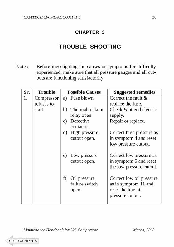
Note : Before investigating the causes or symptoms for difficulty experienced, make sure that all pressure gauges and all cut-outs are functioning satisfactorily.
Sr. Trouble Possible Causes Suggested remedies 1. Compressor
refuses to start
a) Fuse blown b) Thermal lockout
relay open c) Defective
contactor d) High pressure
cutout open. e) Low pressure
cutout open. f) Oil pressure
failure switch open.
Correct the fault & replace the fuse. Check & attend electric supply. Repair or replace. Correct high pressure as in symptom 4 and reset low pressure cutout. Correct low pressure as in symptom 5 and reset the low pressure cutout. Correct low oil pressure as in symptom 11 and reset the low oil pressure cutout.
CAMTECH/2003/E/ACCOMP/1.0
Maintenance Handbook for U/S Compressor March, 2003
21
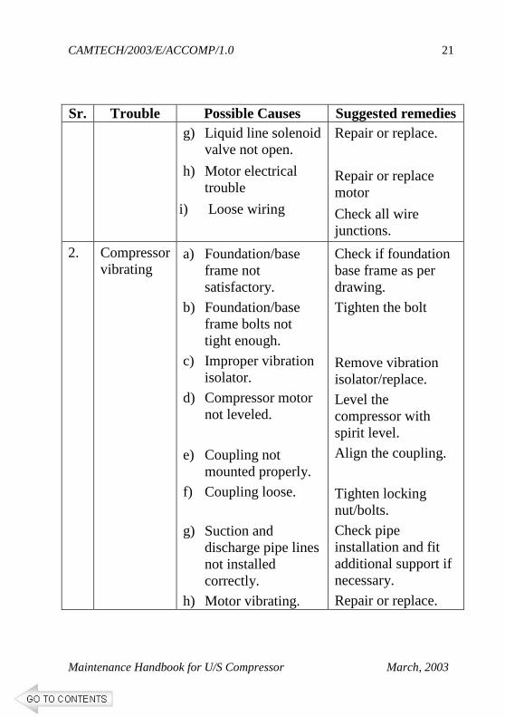
Sr. Trouble Possible Causes Suggested remedies g) Liquid line solenoid
valve not open.
h) Motor electrical trouble
i) Loose wiring
Repair or replace.
Repair or replace motor
Check all wire junctions.
2. Compressor vibrating
a) Foundation/base frame not satisfactory.
b) Foundation/base frame bolts not tight enough.
c) Improper vibration isolator.
d) Compressor motor not leveled.
e) Coupling not mounted properly.
f) Coupling loose.
g) Suction and discharge pipe lines not installed correctly.
h) Motor vibrating.
Check if foundation base frame as per drawing.
Tighten the bolt
Remove vibration isolator/replace.
Level the compressor with spirit level.
Align the coupling.
Tighten locking nut/bolts.
Check pipe installation and fit additional support if necessary.
Repair or replace.
CAMTECH/2003/E/ACCOMP/1.0
Maintenance Handbook for U/S Compressor March, 2003
22
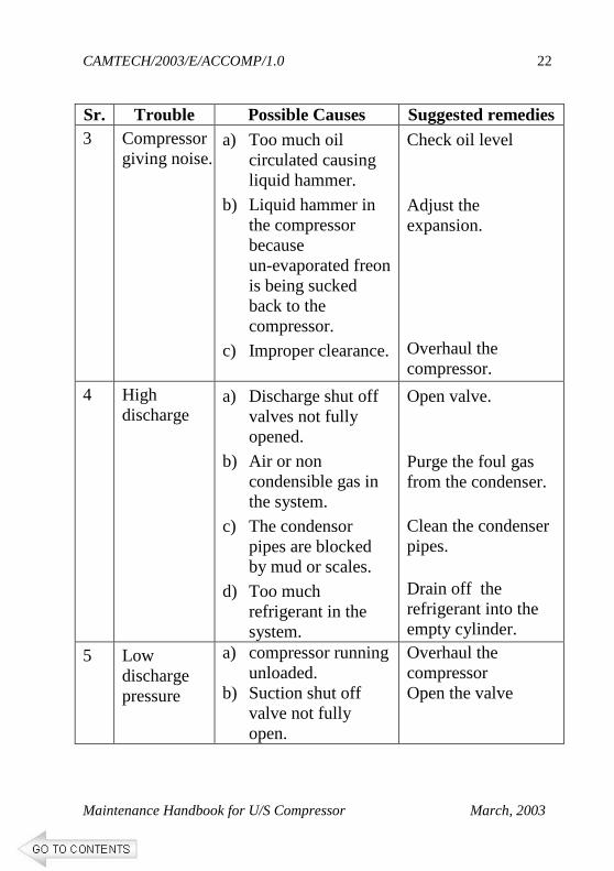
Sr. Trouble Possible Causes Suggested remedies 3 Compressor
giving noise. a) Too much oil
circulated causing liquid hammer.
b) Liquid hammer in the compressor because un-evaporated freon is being sucked back to the compressor.
c) Improper clearance.
Check oil level
Adjust the expansion.
Overhaul the compressor.
4 High discharge
a) Discharge shut off valves not fully opened.
b) Air or non condensible gas in the system.
c) The condensor pipes are blocked by mud or scales.
d) Too much refrigerant in the system.
Open valve.
Purge the foul gas from the condenser.
Clean the condenser pipes.
Drain off the refrigerant into the empty cylinder.
5 Low discharge pressure
a) compressor running unloaded.
b) Suction shut off valve not fully open.
Overhaul the compressor Open the valve
CAMTECH/2003/E/ACCOMP/1.0
Maintenance Handbook for U/S Compressor March, 2003
23
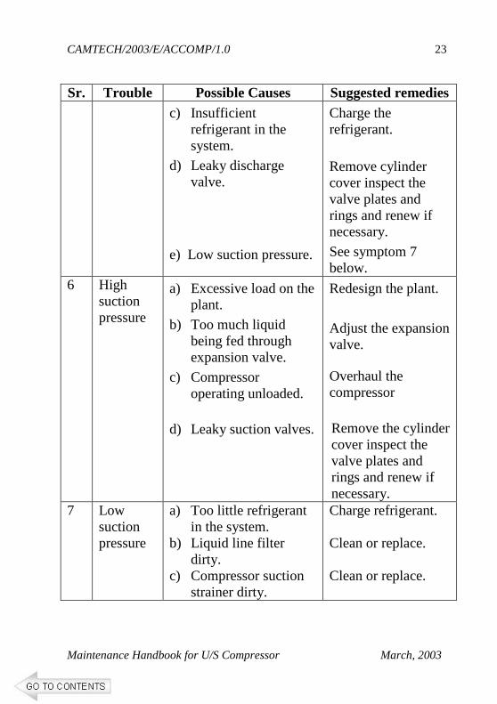
Sr. Trouble Possible Causes Suggested remedies c) Insufficient
refrigerant in the system.
d) Leaky discharge valve.
e) Low suction pressure.
Charge the refrigerant.
Remove cylinder cover inspect the valve plates and rings and renew if necessary.
See symptom 7 below.
6 High suction pressure
a) Excessive load on the plant.
b) Too much liquid being fed through expansion valve.
c) Compressor operating unloaded.
d) Leaky suction valves.
Redesign the plant.
Adjust the expansion valve.
Overhaul the compressor
Remove the cylinder cover inspect the valve plates and rings and renew if necessary.
7 Low suction pressure
a) Too little refrigerant in the system.
b) Liquid line filter dirty.
c) Compressor suction strainer dirty.
Charge refrigerant. Clean or replace. Clean or replace.
CAMTECH/2003/E/ACCOMP/1.0
Maintenance Handbook for U/S Compressor March, 2003
24
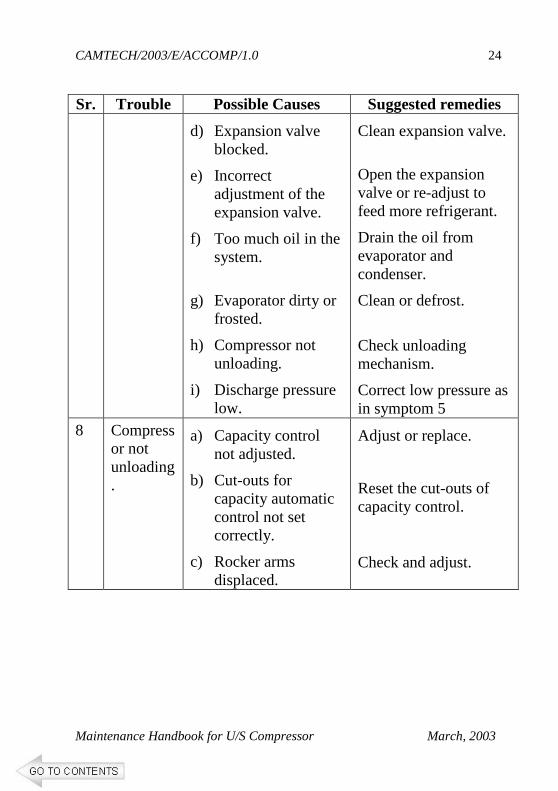
Sr. Trouble Possible Causes Suggested remedies d) Expansion valve
blocked.
e) Incorrect adjustment of the expansion valve.
f) Too much oil in the system.
g) Evaporator dirty or frosted.
h) Compressor not unloading.
i) Discharge pressure low.
Clean expansion valve.
Open the expansion valve or re-adjust to feed more refrigerant.
Drain the oil from evaporator and condenser.
Clean or defrost.
Check unloading mechanism.
Correct low pressure as in symptom 5
8 Compressor not unloading.
a) Capacity control not adjusted.
b) Cut-outs for capacity automatic control not set correctly.
c) Rocker arms displaced.
Adjust or replace.
Reset the cut-outs of capacity control.
Check and adjust.
CAMTECH/2003/E/ACCOMP/1.0
Maintenance Handbook for U/S Compressor March, 2003
25
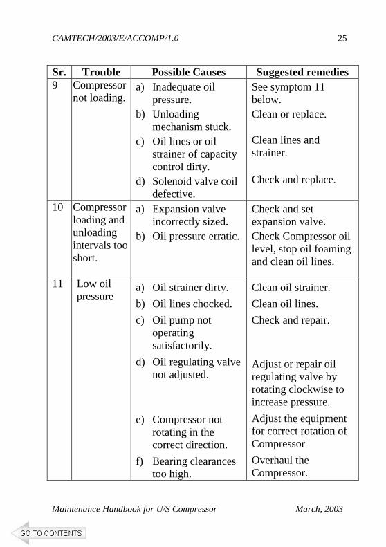
Sr. Trouble Possible Causes Suggested remedies 9 Compressor
not loading. a) Inadequate oil
pressure. b) Unloading
mechanism stuck. c) Oil lines or oil
strainer of capacity control dirty.
d) Solenoid valve coil defective.
See symptom 11 below. Clean or replace.
Clean lines and strainer.
Check and replace.
10 Compressor loading and unloading intervals too short.
a) Expansion valve incorrectly sized.
b) Oil pressure erratic.
Check and set expansion valve. Check Compressor oil level, stop oil foaming and clean oil lines.
11 Low oil pressure
a) Oil strainer dirty.
b) Oil lines chocked.
c) Oil pump not operating satisfactorily.
d) Oil regulating valve not adjusted.
e) Compressor not rotating in the correct direction.
f) Bearing clearances too high.
Clean oil strainer.
Clean oil lines.
Check and repair.
Adjust or repair oil regulating valve by rotating clockwise to increase pressure.
Adjust the equipment for correct rotation of Compressor
Overhaul the Compressor.
CAMTECH/2003/E/ACCOMP/1.0
Maintenance Handbook for U/S Compressor March, 2003
26
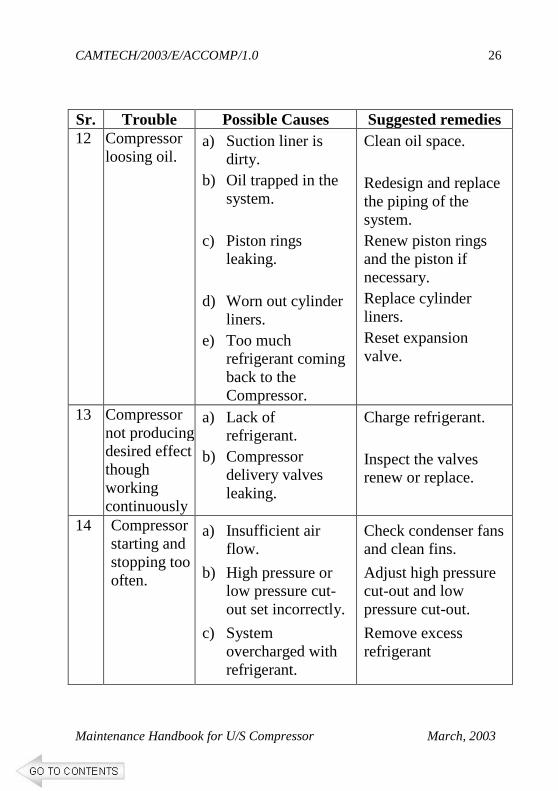
Sr. Trouble Possible Causes Suggested remedies 12 Compressor
loosing oil. a) Suction liner is
dirty. b) Oil trapped in the
system. c) Piston rings
leaking. d) Worn out cylinder
liners. e) Too much
refrigerant coming back to the Compressor.
Clean oil space. Redesign and replace the piping of the system. Renew piston rings and the piston if necessary. Replace cylinder liners. Reset expansion valve.
13 Compressor not producing desired effect though working continuously
a) Lack of refrigerant.
b) Compressor delivery valves leaking.
Charge refrigerant. Inspect the valves renew or replace.
14 Compressor starting and stopping too often.
a) Insufficient air flow.
b) High pressure or low pressure cut-out set incorrectly.
c) System overcharged with refrigerant.
Check condenser fans and clean fins.
Adjust high pressure cut-out and low pressure cut-out.
Remove excess refrigerant
CAMTECH/2003/E/ACCOMP/1.0
Maintenance Handbook for U/S Compressor March, 2003
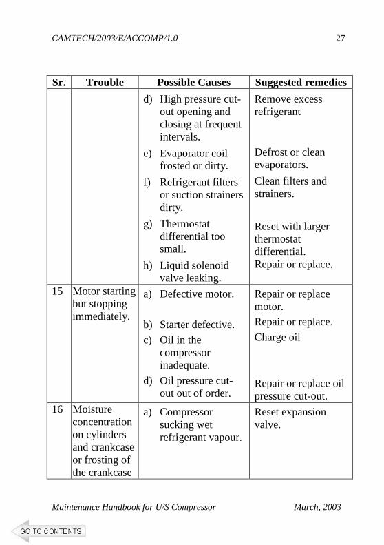
27
Sr. Trouble Possible Causes Suggested remedies d) High pressure cut-
out opening and closing at frequent intervals.
e) Evaporator coil frosted or dirty.
f) Refrigerant filters or suction strainers dirty.
g) Thermostat differential too small.
h) Liquid solenoid valve leaking.
Remove excess refrigerant
Defrost or clean evaporators.
Clean filters and strainers.
Reset with larger thermostat differential. Repair or replace.
15 Motor starting but stopping immediately.
a) Defective motor.
b) Starter defective.
c) Oil in the compressor inadequate.
d) Oil pressure cut-out out of order.
Repair or replace motor. Repair or replace.
Charge oil
Repair or replace oil pressure cut-out.
16 Moisture concentration on cylinders and crankcase or frosting of the crankcase
a) Compressor sucking wet refrigerant vapour.
Reset expansion valve.
CAMTECH/2003/E/ACCOMP/1.0
Maintenance Handbook for U/S Compressor March, 2003
28
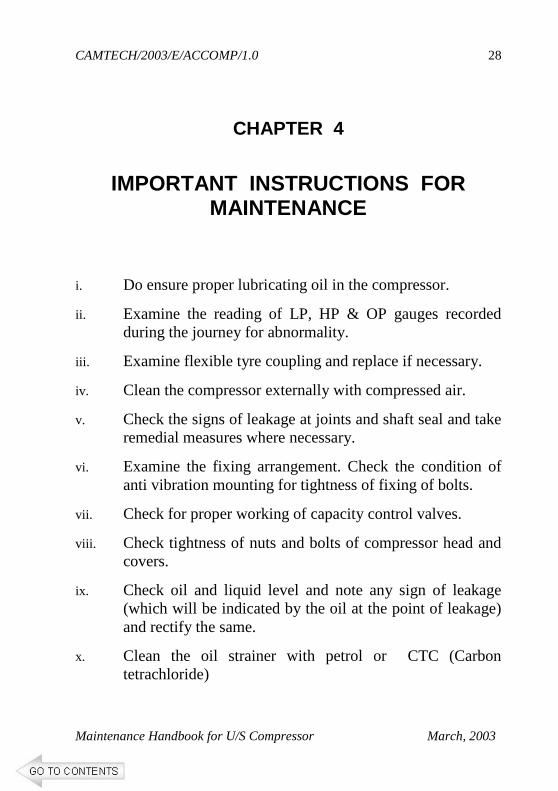
CHAPTER 4
IMPORTANT INSTRUCTIONS FOR MAINTENANCE
i. Do ensure proper lubricating oil in the compressor.
ii. Examine the reading of LP, HP & OP gauges recorded during the journey for abnormality.
iii. Examine flexible tyre coupling and replace if necessary.
iv. Clean the compressor externally with compressed air.
v. Check the signs of leakage at joints and shaft seal and take remedial measures where necessary.
vi. Examine the fixing arrangement. Check the condition of anti vibration mounting for tightness of fixing of bolts.
vii. Check for proper working of capacity control valves.
viii. Check tightness of nuts and bolts of compressor head and covers.
ix. Check oil and liquid level and note any sign of leakage (which will be indicated by the oil at the point of leakage) and rectify the same.
x. Clean the oil strainer with petrol or CTC (Carbon tetrachloride)
CAMTECH/2003/E/ACCOMP/1.0
Maintenance Handbook for U/S Compressor March, 2003
29
xi. Do not allow presence of excess lubricating oil in the compressor.
xii. Do not mix up two different grades of oil.
xiii. All tools instruments should be calibrated properly.
xiv. Cleanliness should be maintained.
xv. Don't procure oil in drums. It should be in 5 - 20 litres containers as per requirement to avoid aging of oil.
xvi. Don’t re-use removed oil from the compressor.
*****
CAMTECH/2003/E/ACCOMP/1.0
Maintenance Handbook for U/S Compressor March, 2003
30
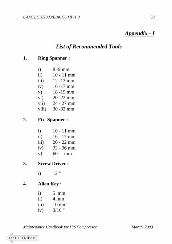
Appendix - I
List of Recommended Tools 1. Ring Spanner :
i) 8 -9 mm ii) 10 - 11 mm iii) 12 -13 mm iv) 16 -17 mm v) 18 -19 mm vi) 20 -22 mm vii) 24 - 27 mm viii) 30 -32 mm
2. Fix Spanner :
i) 10 - 11 mm ii) 16 - 17 mm iii) 20 - 22 mm iv) 32 - 36 mm v) 60 - mm
3. Screw Driver :
i) 12 " 4. Allen Key :
i) 5 mm ii) 4 mm iii) 10 mm iv) 3/16 "
CAMTECH/2003/E/ACCOMP/1.0
Maintenance Handbook for U/S Compressor March, 2003
31
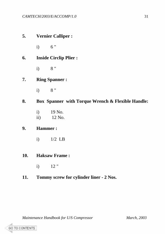
5. Vernier Calliper :
i) 6 "
6. Inside Circlip Plier :
i) 8 " 7. Ring Spanner :
i) 8 "
8. Box Spanner with Torque Wrench & Flexible Handle:
i) 19 No. ii) 12 No.
9. Hammer :
i) 1/2 LB 10. Haksaw Frame :
i) 12 " 11. Tommy screw for cylinder liner - 2 Nos.
CAMTECH/2003/E/ACCOMP/1.0
Maintenance Handbook for U/S Compressor March, 2003
32
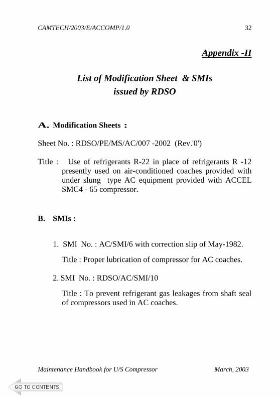
Appendix -II
List of Modification Sheet & SMIs
issued by RDSO
A. Modification Sheets : Sheet No. : RDSO/PE/MS/AC/007 -2002 (Rev.'0')
Title : Use of refrigerants R-22 in place of refrigerants R -12
presently used on air-conditioned coaches provided with under slung type AC equipment provided with ACCEL SMC4 - 65 compressor.
B. SMIs :
1. SMI No. : AC/SMI/6 with correction slip of May-1982.
Title : Proper lubrication of compressor for AC coaches.
2. SMI No. : RDSO/AC/SMI/10
Title : To prevent refrigerant gas leakages from shaft seal of compressors used in AC coaches.
CAMTECH/2003/E/ACCOMP/1.0
Maintenance Handbook for U/S Compressor March, 2003
33
References 1. RDSO Specification no. EL/AC/12 for Refrigerant
compressors used for Railway Air conditioned coaches. 2. Compendium of Modification sheets & Special
Maintenance Instructions for AC & non AC coaches (Mar., 99) issued by RDSO.
3. Unified Maintenance Manual for BG coaches issued by
CAMTECH, Gwalior. 4. Papers presented by participants during the seminar on
"Maintenance of underslung AC coach compressors" held at CAMTECH on 19th & 20th Dec.,2002.


![Handbook [Final] Maintenance Driver](https://img.pdfslide.us/doc/110x75/577d2aad1a28ab4e1ea9cb64/handbook-final-maintenance-driver.jpg)