Embed Size (px)
Citation preview

MINIRAIL
Profiled miniature guideway
• 1• • • • • • • • • • • • • • • • • • • • • • • • • • • • • • • • • • • •
Table of Contents 1 Product overview and technical informations MINIRAIL – a range of high-precision products . . . . . . . . . . . . . . . . . . . . . . . . . .2 MINIRAIL – overview accuracy classes: . . . . . . . . . . . . . . . . . . . . . . . . . . . . . . . .3 MINIRAIL – overview preload categories . . . . . . . . . . . . . . . . . . . . . . . . . . . . . . .3 MINIRAIL – carriage replacement warranty . . . . . . . . . . . . . . . . . . . . . . . . . . . . .3
2 MINIRAIL — Technical highlights Accelerations . . . . . . . . . . . . . . . . . . . . . . . . . . . . . . . . . . . . . . . . . . . . . . . . . . . .4 Lubrication . . . . . . . . . . . . . . . . . . . . . . . . . . . . . . . . . . . . . . . . . . . . . . . . . . . . .4 Ball retention . . . . . . . . . . . . . . . . . . . . . . . . . . . . . . . . . . . . . . . . . . . . . . . . . . . .5 Protection against pollution . . . . . . . . . . . . . . . . . . . . . . . . . . . . . . . . . . . . . . . . .5 Materials . . . . . . . . . . . . . . . . . . . . . . . . . . . . . . . . . . . . . . . . . . . . . . . . . . . . . . .6 Vacuum capacity . . . . . . . . . . . . . . . . . . . . . . . . . . . . . . . . . . . . . . . . . . . . . . . . .6 Packaging . . . . . . . . . . . . . . . . . . . . . . . . . . . . . . . . . . . . . . . . . . . . . . . . . . . . . .6 Smoothness and displacement force . . . . . . . . . . . . . . . . . . . . . . . . . . . . . . . . . .7 Clamping element for safety purposes . . . . . . . . . . . . . . . . . . . . . . . . . . . . . . . . .7
3 Technical Data Accuracy classes . . . . . . . . . . . . . . . . . . . . . . . . . . . . . . . . . . . . . . . . . . . . . . . . .8 Running accuracy . . . . . . . . . . . . . . . . . . . . . . . . . . . . . . . . . . . . . . . . . . . . . . . .8 Preload classes V0, V1 . . . . . . . . . . . . . . . . . . . . . . . . . . . . . . . . . . . . . . . . . . . .8 Rail lengths . . . . . . . . . . . . . . . . . . . . . . . . . . . . . . . . . . . . . . . . . . . . . . . . . . . . .9 Tolerances for rail lengths and fixing holes . . . . . . . . . . . . . . . . . . . . . . . . . . . . . .9 Lubrication . . . . . . . . . . . . . . . . . . . . . . . . . . . . . . . . . . . . . . . . . . . . . . . . . . . .10 Lubrication with grease . . . . . . . . . . . . . . . . . . . . . . . . . . . . . . . . . . . . . . . . . . .10 Lubrication with oil . . . . . . . . . . . . . . . . . . . . . . . . . . . . . . . . . . . . . . . . . . . . . . .10 Re-lubrication . . . . . . . . . . . . . . . . . . . . . . . . . . . . . . . . . . . . . . . . . . . . . . . . . .10 Permissible speeds and accelerations . . . . . . . . . . . . . . . . . . . . . . . . . . . . . . . .11 Permissible operating temperatures . . . . . . . . . . . . . . . . . . . . . . . . . . . . . . . . . .11 Materials . . . . . . . . . . . . . . . . . . . . . . . . . . . . . . . . . . . . . . . . . . . . . . . . . . . . . .11 Dimension table, loading capacities . . . . . . . . . . . . . . . . . . . . . . . . . . . . . . . 12/13 Accessories and options . . . . . . . . . . . . . . . . . . . . . . . . . . . . . . . . . . . . . . . . . .14 Plastic plugs . . . . . . . . . . . . . . . . . . . . . . . . . . . . . . . . . . . . . . . . . . . . . . . . . . .14 Multi-part rails (ZG) . . . . . . . . . . . . . . . . . . . . . . . . . . . . . . . . . . . . . . . . . . . . . .14
4 Sizing and installation guidelines Dynamic loading capacity C . . . . . . . . . . . . . . . . . . . . . . . . . . . . . . . . . . . . . . .15 Tightening torques for rails and carriages . . . . . . . . . . . . . . . . . . . . . . . . . . . . .16 Configuration of the lateral location sides . . . . . . . . . . . . . . . . . . . . . . . . . . . . . .17 Configuration of assembly surfaces . . . . . . . . . . . . . . . . . . . . . . . . . . . . . . . . . .17 Geometrical and position accuracy of the support surfaces . . . . . . . . . . . . . . . .18 Parallelism tolerances of the locating surfaces . . . . . . . . . . . . . . . . . . . . . . . . . .19 Mounting instructions . . . . . . . . . . . . . . . . . . . . . . . . . . . . . . . . . . . . . . . . . . . .19 As delivered condition . . . . . . . . . . . . . . . . . . . . . . . . . . . . . . . . . . . . . . . . . . . .19 Transportation and intermediate storage . . . . . . . . . . . . . . . . . . . . . . . . . . . . . .19
5 Ordering information MINIRAIL . . . . . . . . . . . . . . . . . . . . . . . . . . . . . . . . . .20
• 2• • • • • • • • • • • • • • • • • • • • • • • • • • • •
7 mm MNNXL 9
MNNXL 12
MNNXL 15
MNNL 9
MNNL 12
MNN 9
MNNS 7
MNNS 9
MNNL 14
MNNL 18
MNNL 24
MNNL 42
MNN 14
MNN 18
MNN 24
MNN 42
MNNS 12
MNNS 15
MNN 12
MNNL 15
MNN 15
MNNXL 7
MNNL 7
MNN 7
9 mm
12 mm
15 mm
14 mm
24 mm
42 mm
18 mm
1Product overview and technical informations
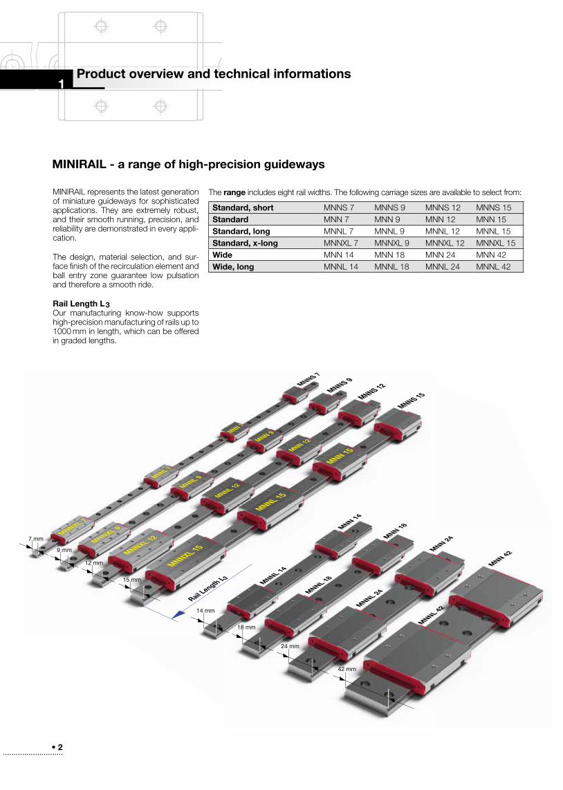
MINIRAIL - a range of high-precision guideways
MlNlRAlL represents the latest generation of miniature guideways for sophisticated applications . They are extremely robust, and their smooth running, precision, and reliability are demonstrated in every appli-cation .
The design, material selection, and sur-face finish of the recirculation element and ball entry zone guarantee low pulsation and therefore a smooth ride .
Rail Length L3Our manufacturing know-how supports high-precision manufacturing of rails up to 1000 mm in length, which can be offered in graded lengths .
The range includes eight rail widths . The following carriage sizes are available to select from:
Rail Length L3
Standard, short MNNS 7 MNNS 9 MNNS 12 MNNS 15Standard MNN 7 MNN 9 MNN 12 MNN 15Standard, long MNNL 7 MNNL 9 MNNL 12 MNNL 15Standard, x-long MNNXL 7 MNNXL 9 MNNXL 12 MNNXL 15Wide MNN 14 MNN 18 MNN 24 MNN 42Wide, long MNNL 14 MNNL 18 MNNL 24 MNNL 42
• 3• • • • • • • • • • • • • • • • • • • • • • • • • • • • • • • • • • • •
7 mm MNNXL 9
MNNXL 12
MNNXL 15
MNNL 9
MNNL 12
MNN 9
MNNS 7
MNNS 9
MNNL 14
MNNL 18
MNNL 24
MNNL 42
MNN 14
MNN 18
MNN 24
MNN 42
MNNS 12
MNNS 15
MNN 12
MNNL 15
MNN 15
MNNXL 7
MNNL 7
MNN 7
9 mm
12 mm
15 mm
14 mm
24 mm
42 mm
18 mm
G3 G1
G1
G3
A
A
B2
B2
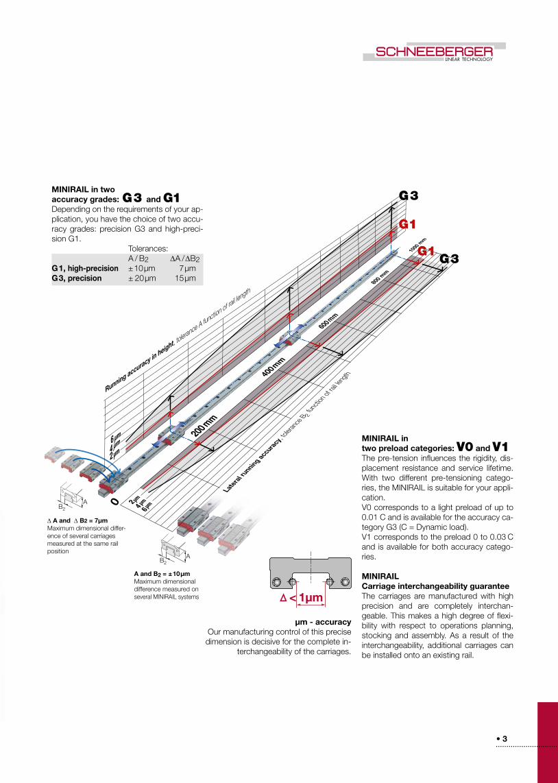
MINIRAIL in two accuracy grades: G3 and G1Depending on the requirements of your ap-plication, you have the choice of two accu-racy grades: precision G3 and high-preci-sion G1 . Tolerances: A / B2 ∆A / ∆B2G1, high-precision ±10µm 7µmG3, precision ± 20µm 15µm
Running accuracy in height, tolerance A function of ra
il length
Latera
l running ac
cura
cy, to
leran
ce B 2
functi
on of
rail le
ngth
MINIRAIL in two preload categories: V0 and V1The pre-tension influences the rigidity, dis-placement resistance and service lifetime . With two different pre-tensioning catego-ries, the MINIRAIL is suitable for your appli-cation .V0 corresponds to a light preload of up to 0 .01 C and is available for the accuracy ca-tegory G3 (C = Dynamic load) .V1 corresponds to the preload 0 to 0 .03 C and is available for both accuracy catego-ries .
MINIRAIL Carriage interchangeability guarantee The carriages are manufactured with high precision and are completely interchan-geable . This makes a high degree of flexi-bility with respect to operations planning, stocking and assembly . As a result of the interchangeability, additional carriages can be installed onto an existing rail .
A and B2 = ±10µm Maximum dimensional difference measured on several MINIRAIL systems
∆ A and ∆ B2 = 7µm Maximum dimensional differ-en ce of several carriages measured at the same rail position
µm - accuracyOur manufacturing control of this precise dimension is decisive for the complete in-
terchangeability of the carriages .
• 4• • • • • • • • • • • • • • • • • • • • • • • • • • • •
2
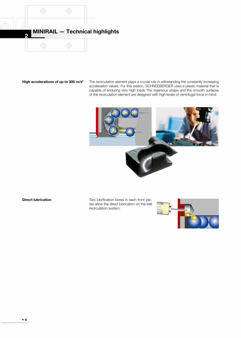
High accelerations of up to 300 m/s2 The recirculation element plays a crucial role in withstanding the constantly increasing acceleration values . For this reason, SCHNEEBERGER uses a plastic material that is capable of enduring very high loads The ingenious shape and the smooth surfaces of the recirculation element are designed with high levels of centrifugal force in mind .
Two lubrification bores in each front pla-tes allow the direct lubrication on the ball recirculation system .
Direct lubrication
MINIRAIL — Technical highlights
• 5• • • • • • • • • • • • • • • • • • • • • • • • • • • • • • • • • • • •
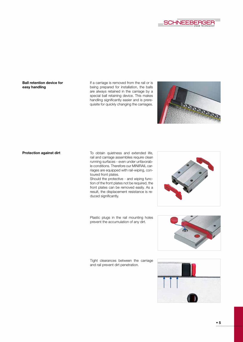
To obtain quietness and extended life, rail and carriage assemblies require clean run ning surfaces - even under unfavorab-le conditions . Therefore our MINIRAIL car-riages are equipped with rail-wiping, con-toured front plates .Should the protective - and wiping func-tion of the front plates not be required, the front plates can be removed easily . As a result, the displacement resistance is re-duced significantly .
Plastic plugs in the rail mounting holes prevent the accumulation of any dirt .
Tight clearances between the carriage and rail prevent dirt penetration .
Ball retention device for easy handling
If a carriage is removed from the rail or is being prepared for installation, the balls are always retained in the carriage by a special ball retaining device . This makes handling significantly easier and is prere-quisite for quickly changing the carriages .
Protection against dirt

• 6• • • • • • • • • • • • • • • • • • • • • • • • • • • •
MINIRAIL can be operated in high vacu-um without any wiper (max . 10-7 mbar) .
Protective packaging Carriages and rails are packed carefully and ready for installation . In the process MINI-RAIL carriages are shipped on a pro tective rail, in order to prevent any impairment by dirt or debris .
Vacuum capacity
High-grade materials All rails and carriages are manufactured from corrosion-resistant, through-harde-ned steel and are suitable for utilization in the most diverse applications .
• 7• • • • • • • • • • • • • • • • • • • • • • • • • • • • • • • • • • • •
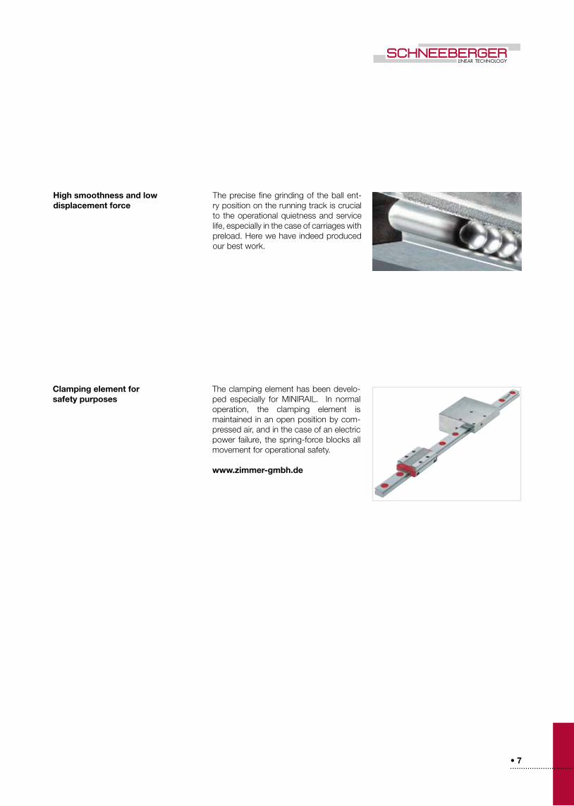
Clamping element for safety purposes
The clamping element has been develo-ped especially for MINIRAIL . In normal operation, the clamping element is maintained in an open position by com-pressed air, and in the case of an electric power failure, the spring-force blocks all movement for operational safety .
www.zimmer-gmbh.de
The precise fine grinding of the ball ent-ry position on the running track is crucial to the operational quietness and service life, especially in the case of carriages with pre load . Here we have indeed produced our best work .
High smoothness and low displacement force
• 8• • • • • • • • • • • • • • • • • • • • • • • • • • • •
3
B2
A
0 200 400 600 800 1000 1200
18 .0
16 .0
14 .0
12 .0
10 .0
8 .0
6 .0
4 .0
2 .0
G3
G1
Technical Data
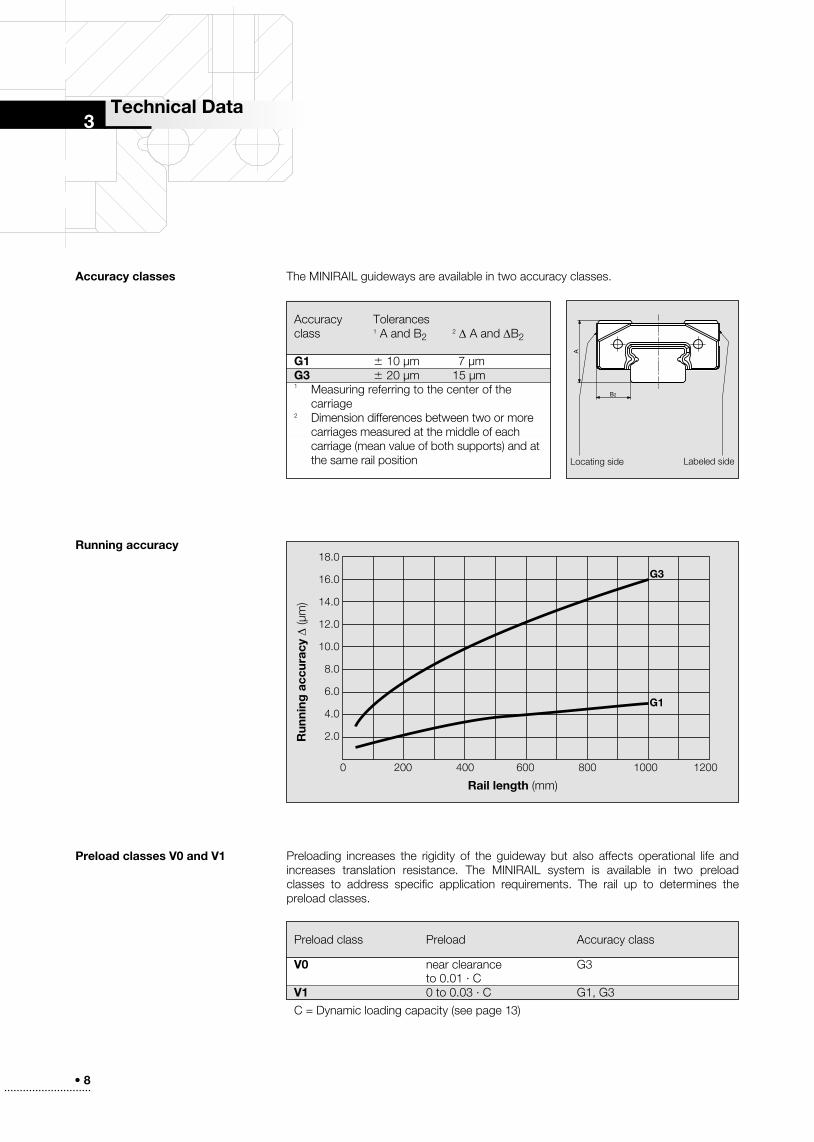
The MINIRAIL guideways are available in two accuracy classes .Accuracy classes
Running accuracy
Preload classes V0 and V1
Accuracy Tolerancesclass 1 A and B2
2 ∆ A and ∆B2
G1 6 10 µm 7 µmG3 6 20 µm 15 µm1 Measuring referring to the center of the carriage 2 Dimension differences between two or more carriages measured at the middle of each carriage (mean value of both supports) and at the same rail position Locating side Labeled side
Rail length (mm)
Run
ning
acc
urac
y ∆
(µm
)
Preload class Preload Accuracy class
V0 near clearance G3 to 0 .01 · CV1 0 to 0 .03 · C G1, G3
C = Dynamic loading capacity (see page 13)
Preloading increases the rigidity of the guideway but also affects operational life and increases translation resistance . The MINIRAIL system is available in two preload classes to address specific application requirements . The rail up to determines the preload classes .
• 9• • • • • • • • • • • • • • • • • • • • • • • • • • • • • • • • • • • •
L5 L4 L10
L3
L4
L3
0 X1
X2
X3
Xn
jnt
n x L4
L8
L5 L4
L3
L10
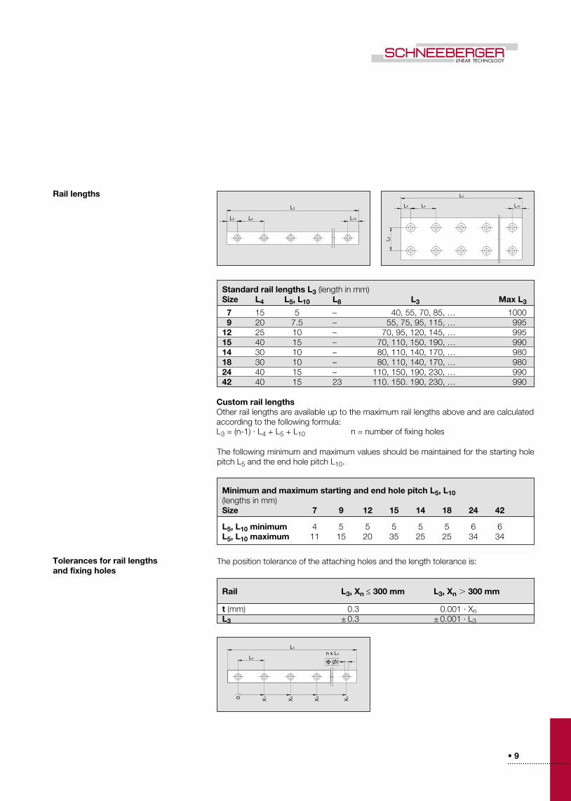
Rail lengths
Tolerances for rail lengthsand fixing holes
Standard rail lengths L3 (length in mm) Size L4 L5, L10 L8 L3 Max L3
7 15 5 – 40, 55, 70, 85, … 1000 9 20 7 .5 – 55, 75, 95, 115, … 995 12 25 10 – 70, 95, 120, 145, … 995 15 40 15 – 70, 110, 150, 190, … 990 14 30 10 – 80, 110, 140, 170, … 980 18 30 10 – 80, 110, 140, 170, … 980 24 40 15 – 110, 150, 190, 230, … 990 42 40 15 23 110 . 150 . 190, 230, … 990
The following minimum and maximum values should be maintained for the starting hole pitch L5 and the end hole pitch L10 .
Custom rail lengthsOther rail lengths are available up to the maximum rail lengths above and are calculated according to the following formula: L3 = (n-1) · L4 + L5 + L10 n = number of fixing holes
Minimum and maximum starting and end hole pitch L5, L10 (lengths in mm) Size 7 9 12 15 14 18 24 42
L5, L10 minimum 4 5 5 5 5 5 6 6L5, L10 maximum 11 15 20 35 25 25 34 34
Rail L3, Xn ≤ 300 mm L3, Xn 300 mm
t (mm) 0 .3 0 .001 · XnL3 ± 0 .3 ± 0 .001 · L3
The position tolerance of the attaching holes and the length tolerance is:

• 10• • • • • • • • • • • • • • • • • • • • • • • • • • • •
Lubrication
Lubrication with grease
Lubrication with oil
Re-lubrication
The front plates include two lubrication holes to allow independent lubrication for the right and left side of the carriage . This ensures that all tracks of the carriageare provided with lubricant, in all installation orientations .
At delivery the carriages are slightly oiled . Prior to operation the carriages must be lubri-cated! Subsequent lubrication depends upon environmental conditions as well as the nature and type of the load . Guarantees regarding subsequent lubrication intervals can only be provided through the user's own tests and experience . In all cases, the recom-mendations provided by the lubricant manufacturer must be followed .
For lubrication with oil, SCHNEEBERGER recommends mineral oil CLP (DIN 51517) or HLP (DIN 51524) in the viscosity range of ISO VG32 to ISO VG150 in accordance with DIN 51519 .For lubrication with grease, SCHNEEBERGER recommends grease KP2K or KP1K inaccordance with DIN 51825 .
A re-lubrication set with an appropriate oil can be ordered at SCHNEEBERGER with the ordering code MNW .
During the lubrication the carriages have to be moved on the rail in order to distribute the lubricant .
During the lubrication the carriages have to be moved on the rail in order to distribute the lubricant .
Guideline values based on the following assumption:- Load ratio C/P* = 10- Speed of 1 m/s- Stroke of 150 mm Re-lubrication interval = 3000 km
*C = dynamic loading capacity / P = equivalent force
Quantity of grease in cm3
MNNS 70 .03
MNNS 90 .05
MNNS 120 .09
MNNS 150 .16
MNN 70 .04
MNN 90 .09
MNN120 .15
MNN 150 .25
MNN 140 .05
MNN 180 .11
MNN 240 .20
MNN 420 .33
MNNL 70 .05
MNNL 90 .11
MNNL 120 .20
MNNL 150 .35
MNNL 140 .07
MNNL 180 .14
MNNL 240 .26
MNNL 420 .45
MNNXL 70 .07
MNNXL 90 .14
MNNXL 120 .26
MNNXL 150 .45

• 11• • • • • • • • • • • • • • • • • • • • • • • • • • • • • • • • • • • •
Permissible speeds and accelerations
Permissible operating temperatures
Materials
MINIRAIL guideways can be used at operating temperatures between -40°C and +80°C . Short term temperatures up to +120°C are permissible .
All steel parts are made from through hardened stainless steel . Plastic components are injection-molded using POM and TPE .
General applications under normal operating conditions:
Speeds up to 5 m/s
Accelerations up to 300 m/s2
• 12• • • • • • • • • • • • • • • • • • • • • • • • • • • •
eN
B
J
g A
B1B2
o
g2
J1
f2
f1
L5 L4
L3
L10
L2 L2
L1
L6
L
L1
L6
L
L1
L6
L
m1
MNN MNNL MNNXL
X
X
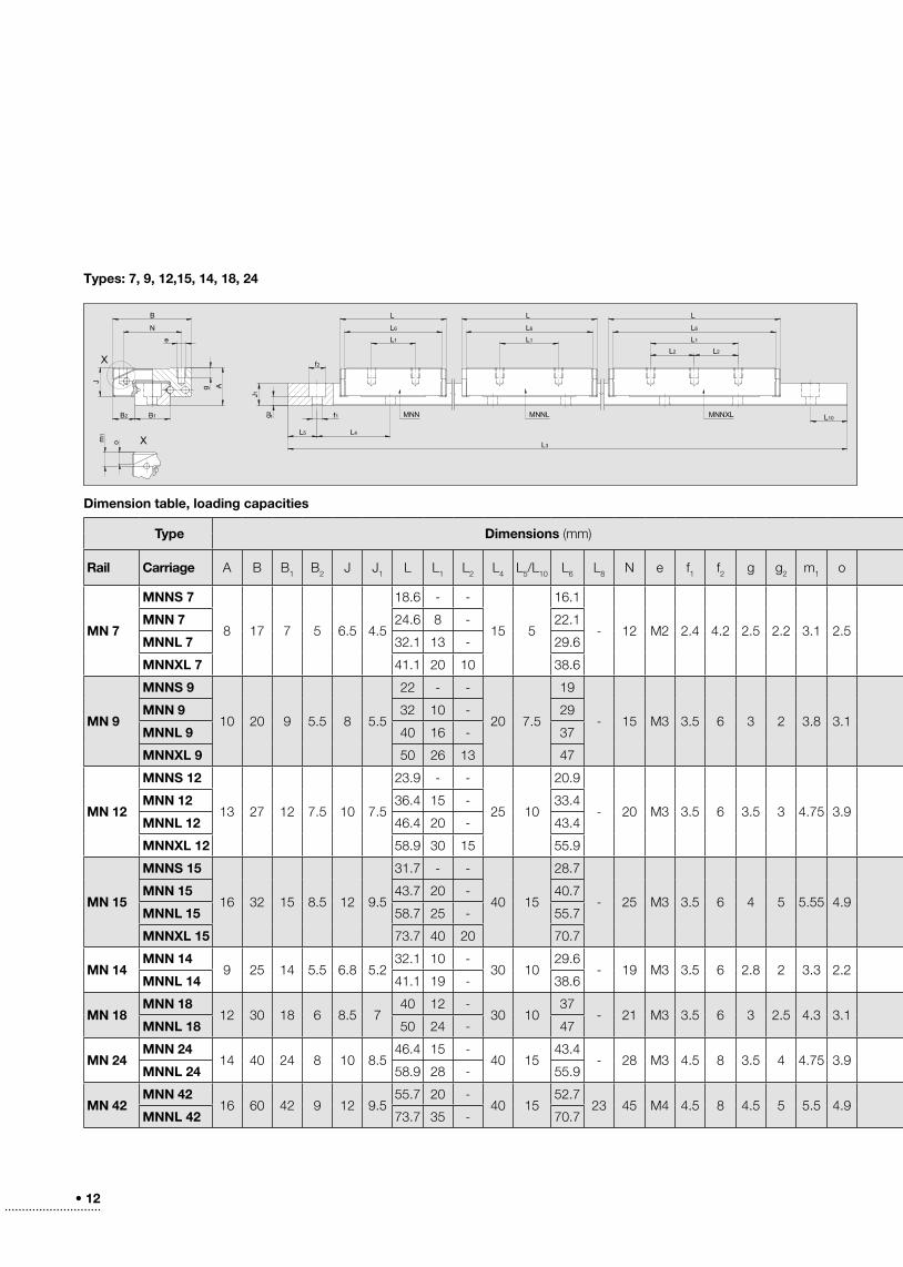
Dimension table, loading capacities
Types: 7, 9, 12,15, 14, 18, 24
Type Dimensions (mm) Loading capacities Moments WeightsCarriage Rail
Rail Carriage A B B1 B2 J J1 L L1 L2 L4 L5/L10 L6 L8 N e f1 f2 g g2 m1 oCo(N)
C(N)
M0Q
(Nm)M0L
(Nm)MQ
(Nm)ML
(Nm) (g) (g/m)
MN 7
MNNS 7
8 17 7 5 6 .5 4 .5
18 .6 - -
15 5
16 .1
- 12 M2 2 .4 4 .2 2 .5 2 .2 3 .1 2 .5
935 645 3 .4 1 .6 2 .3 1 .1 9
216MNN 7 24 .6 8 - 22 .1 1560 925 5 .6 4 .3 3 .3 2 .5 13
MNNL 7 32 .1 13 - 29 .6 2340 1230 8 .4 9 .3 4 .4 4 .9 18
MNNXL 7 41 .1 20 10 38 .6 3275 1550 11 .8 17 .4 5 .6 8 .2 23
MN 9
MNNS 9
10 20 9 5 .5 8 5 .5
22 - -
20 7 .5
19
- 15 M3 3 .5 6 3 2 3 .8 3 .1
1385 1040 6 .5 2 .8 2 .8 4 .8 16
309MNN 9 32 10 - 29 2770 1690 12 .9 10 .2 7 .9 6 .2 24
MNNL 9 40 16 - 37 3880 2140 18 .1 19 .4 9 .9 10 .7 31
MNNXL 9 50 26 13 47 5270 2645 24 .5 34 .5 12 .3 17 .3 40
MN 12
MNNS 12
13 27 12 7 .5 10 7 .5
23 .9 - -
25 10
20 .9
- 20 M3 3 .5 6 3 .5 3 4 .75 3 .9
1735 1420 10 .6 3 .6 8 .7 3 29
598MNN 12 36 .4 15 - 33 .4 3900 2510 23 .8 16 .3 15 .3 10 .4 47
MNNL 12 46 .4 20 - 43 .4 5630 3240 34 .4 32 .9 19 .8 18 .9 63
MNNXL 12 58 .9 30 15 55 .9 7800 4070 47 .6 61 .1 24 .8 31 .9 81
MN 15
MNNS 15
16 32 15 8 .5 12 9 .5
31 .7 - -
40 15
28 .7
- 25 M3 3 .5 6 4 5 5 .55 4 .9
3120 2435 23 .7 9 .4 18 .5 7 .3 56
996MNN 15 43 .7 20 - 40 .7 5620 3680 42 .7 28 .1 27 .9 18 .4 81
MNNL 15 58 .7 25 - 55 .7 8740 5000 66 .4 65 .5 38 .1 37 .6 114
MNNXL 15 73 .7 40 20 70 .7 11855 6200 90 .1 116 .5 47 .1 60 .9 146
MN 14MNN 14
9 25 14 5 .5 6 .8 5 .232 .1 10 -
30 1029 .6
- 19 M3 3 .5 6 2 .8 2 3 .3 2 .22340 1230 16 .6 9 .3 8 .7 4 .9 25
518MNNL 14 41 .1 19 - 38 .6 3275 1550 23 .3 17 .4 11 8 .2 33
MN 18MNN 18
12 30 18 6 8 .5 740 12 -
30 1037
- 21 M3 3 .5 6 3 2 .5 4 .3 3 .13880 2140 35 .5 19 .4 19 .6 10 .7 47
915MNNL 18 50 24 - 47 5270 2645 48 .2 34 .5 24 .2 17 .3 60
MN 24MNN 24
14 40 24 8 10 8 .546 .4 15 -
40 1543 .4
- 28 M3 4 .5 8 3 .5 4 4 .75 3 .95630 3240 68 .2 32 .9 39 .2 18 .9 84
1473MNNL 24 58 .9 28 - 55 .9 7800 4070 94 .4 61 .1 49 .3 31 .9 109
MN 42MNN 42
16 60 42 9 12 9 .555 .7 20 -
40 1552 .7
23 45 M4 4 .5 8 4 .5 5 5 .5 4 .98110 4750 171 .2 56 .8 100 .3 33 .3 169
2828MNNL 42 73 .7 35 - 70 .7 11855 6200 250 .2 116 .5 130 .8 60 .9 231
• 13• • • • • • • • • • • • • • • • • • • • • • • • • • • • • • • • • • • •
X
X
L5 L4
f1 L10
L3
g2
J1
f2
L1
L6
L
L1
L6
L
eNB
g A
L8
B1B2
J
MNN MNNL
m1 o
MQ/M0Q
Roll
C/C0 C/C0
ML/M0L
Pitch
ML/
M0L
Yaw
C0
C
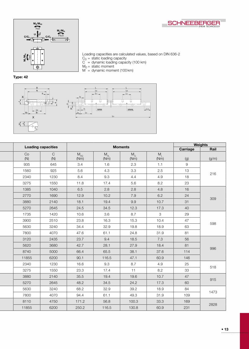
Type: 42
Loading capacities are calculated values, based on DIN 636-2C0 = static loading capacityC = dynamic loading capacity (100 km)M0 = static momentM = dynamic moment (100 km)
Type Dimensions (mm) Loading capacities Moments WeightsCarriage Rail
Rail Carriage A B B1 B2 J J1 L L1 L2 L4 L5/L10 L6 L8 N e f1 f2 g g2 m1 oCo(N)
C(N)
M0Q
(Nm)M0L
(Nm)MQ
(Nm)ML
(Nm) (g) (g/m)
MN 7
MNNS 7
8 17 7 5 6 .5 4 .5
18 .6 - -
15 5
16 .1
- 12 M2 2 .4 4 .2 2 .5 2 .2 3 .1 2 .5
935 645 3 .4 1 .6 2 .3 1 .1 9
216MNN 7 24 .6 8 - 22 .1 1560 925 5 .6 4 .3 3 .3 2 .5 13
MNNL 7 32 .1 13 - 29 .6 2340 1230 8 .4 9 .3 4 .4 4 .9 18
MNNXL 7 41 .1 20 10 38 .6 3275 1550 11 .8 17 .4 5 .6 8 .2 23
MN 9
MNNS 9
10 20 9 5 .5 8 5 .5
22 - -
20 7 .5
19
- 15 M3 3 .5 6 3 2 3 .8 3 .1
1385 1040 6 .5 2 .8 2 .8 4 .8 16
309MNN 9 32 10 - 29 2770 1690 12 .9 10 .2 7 .9 6 .2 24
MNNL 9 40 16 - 37 3880 2140 18 .1 19 .4 9 .9 10 .7 31
MNNXL 9 50 26 13 47 5270 2645 24 .5 34 .5 12 .3 17 .3 40
MN 12
MNNS 12
13 27 12 7 .5 10 7 .5
23 .9 - -
25 10
20 .9
- 20 M3 3 .5 6 3 .5 3 4 .75 3 .9
1735 1420 10 .6 3 .6 8 .7 3 29
598MNN 12 36 .4 15 - 33 .4 3900 2510 23 .8 16 .3 15 .3 10 .4 47
MNNL 12 46 .4 20 - 43 .4 5630 3240 34 .4 32 .9 19 .8 18 .9 63
MNNXL 12 58 .9 30 15 55 .9 7800 4070 47 .6 61 .1 24 .8 31 .9 81
MN 15
MNNS 15
16 32 15 8 .5 12 9 .5
31 .7 - -
40 15
28 .7
- 25 M3 3 .5 6 4 5 5 .55 4 .9
3120 2435 23 .7 9 .4 18 .5 7 .3 56
996MNN 15 43 .7 20 - 40 .7 5620 3680 42 .7 28 .1 27 .9 18 .4 81
MNNL 15 58 .7 25 - 55 .7 8740 5000 66 .4 65 .5 38 .1 37 .6 114
MNNXL 15 73 .7 40 20 70 .7 11855 6200 90 .1 116 .5 47 .1 60 .9 146
MN 14MNN 14
9 25 14 5 .5 6 .8 5 .232 .1 10 -
30 1029 .6
- 19 M3 3 .5 6 2 .8 2 3 .3 2 .22340 1230 16 .6 9 .3 8 .7 4 .9 25
518MNNL 14 41 .1 19 - 38 .6 3275 1550 23 .3 17 .4 11 8 .2 33
MN 18MNN 18
12 30 18 6 8 .5 740 12 -
30 1037
- 21 M3 3 .5 6 3 2 .5 4 .3 3 .13880 2140 35 .5 19 .4 19 .6 10 .7 47
915MNNL 18 50 24 - 47 5270 2645 48 .2 34 .5 24 .2 17 .3 60
MN 24MNN 24
14 40 24 8 10 8 .546 .4 15 -
40 1543 .4
- 28 M3 4 .5 8 3 .5 4 4 .75 3 .95630 3240 68 .2 32 .9 39 .2 18 .9 84
1473MNNL 24 58 .9 28 - 55 .9 7800 4070 94 .4 61 .1 49 .3 31 .9 109
MN 42MNN 42
16 60 42 9 12 9 .555 .7 20 -
40 1552 .7
23 45 M4 4 .5 8 4 .5 5 5 .5 4 .98110 4750 171 .2 56 .8 100 .3 33 .3 169
2828MNNL 42 73 .7 35 - 70 .7 11855 6200 250 .2 116 .5 130 .8 60 .9 231
• 14• • • • • • • • • • • • • • • • • • • • • • • • • • • •
t
4
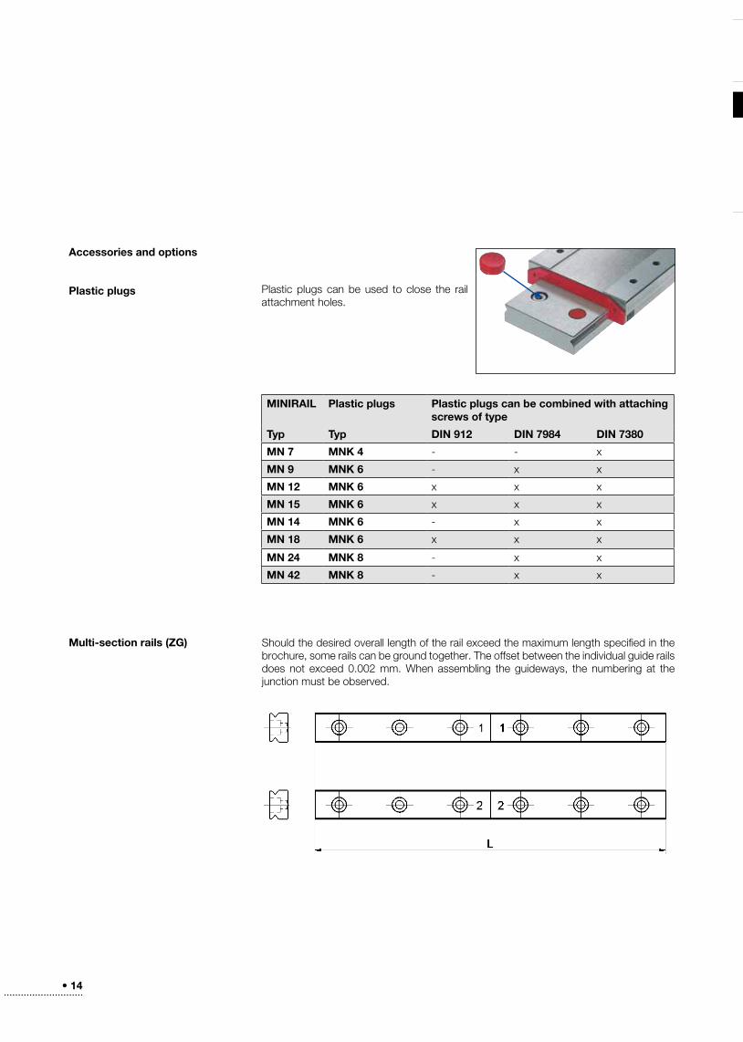
Accessories and options
Plastic plugs
Multi-section rails (ZG) Should the desired overall length of the rail exceed the maximum length specified in the brochure, some rails can be ground together . The offset between the individual guide rails does not exceed 0 .002 mm . When assembling the guideways, the numbering at the junction must be observed .
Plastic plugs can be used to close the rail attachment holes .
MINIRAIL Plastic plugs Plastic plugs can be combined with attaching screws of type
Typ Typ DIN 912 DIN 7984 DIN 7380
MN 7 MNK 4 - - x
MN 9 MNK 6 - x x
MN 12 MNK 6 x x x
MN 15 MNK 6 x x x
MN 14 MNK 6 - x x
MN 18 MNK 6 x x x
MN 24 MNK 8 - x x
MN 42 MNK 8 - x x
• 15• • • • • • • • • • • • • • • • • • • • • • • • • • • • • • • • • • • •
4
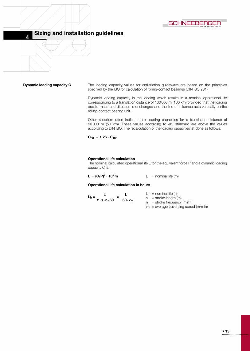
Dynamic loading capacity C The loading capacity values for anti-friction guideways are based on the principles specified by the ISO for calculation of rolling-contact bearings (DIN ISO 281) .
Dynamic loading capacity is the loading which results in a nominal operational life corresponding to a translation distance of 100 000 m (100 km) provided that the loading due to mass and direction is unchanged and the line of influence acts vertically on the rolling-contact bearing unit .
Other suppliers often indicate their loading capacities for a translation distance of 50 000 m (50 km) . These values according to JIS standard are above the values according to DIN ISO . The recalculation of the loading capacities ist done as follows:
C50 = 1.26 · C100
Operational life calculationThe nominal calculated operational life L for the equivalent force P and a dynamic loading capacity C is:
L = (C/P)3 · 105 m L = nominal life (m)
Operational life calculation in hours
Lh = nominal life (h) s = stroke length (m) n = stroke frequency (min-1) vm = average traversing speed (m/min)
Sizing and installation guidelines
Lh = L = L 2 · s · n · 60 60 · vm
• 16• • • • • • • • • • • • • • • • • • • • • • • • • • • •
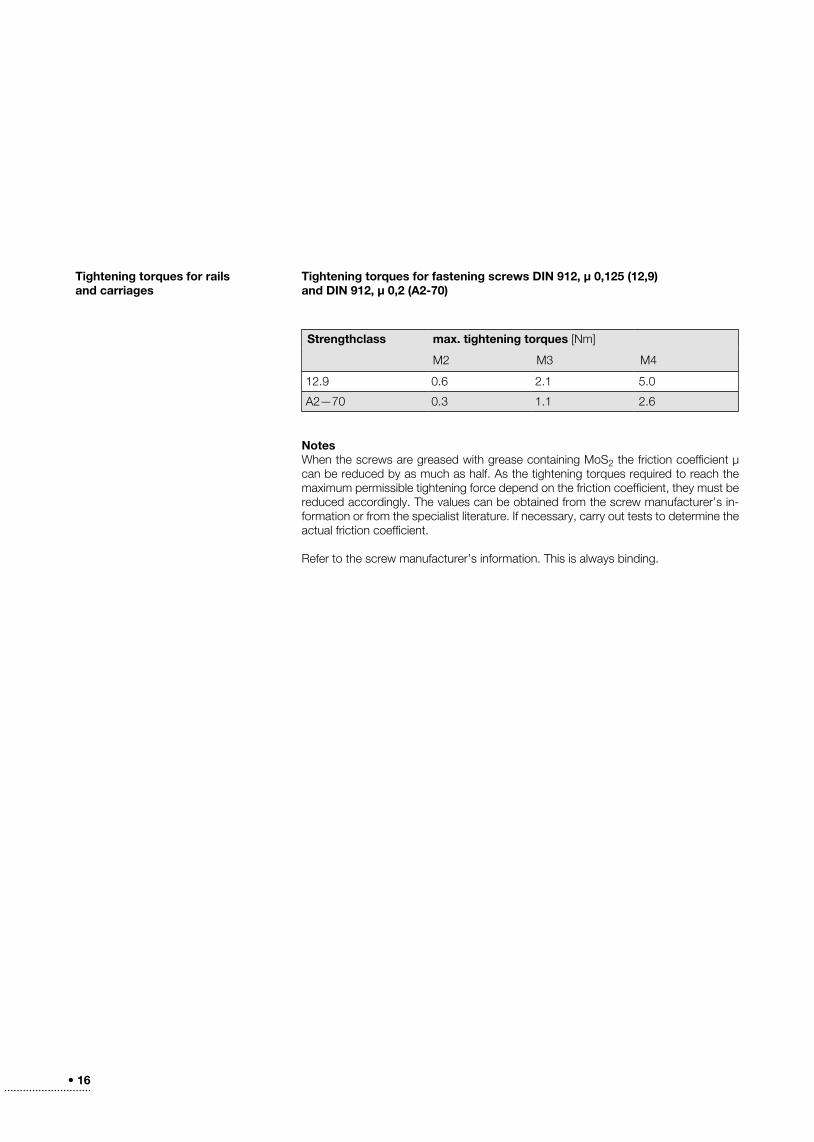
Tightening torques for fastening screws DIN 912, µ 0,125 (12,9)and DIN 912, µ 0,2 (A2-70)
Notes When the screws are greased with grease containing MoS2 the friction coefficient µ can be reduced by as much as half . As the tightening torques required to reach the maximum permissible tightening force depend on the friction coefficient, they must be reduced accordingly . The values can be obtained from the screw manufacturer’s in-formation or from the specialist literature . If necessary, carry out tests to determine the actual friction coefficient .
Refer to the screw manufacturer’s information . This is always binding .
Tightening torques for rails and carriages
Strengthclass max. tightening torques [Nm]
M2 M3 M4
12 .9 0 .6 2 .1 5 .0
A2—70 0 .3 1 .1 2 .6
• 17• • • • • • • • • • • • • • • • • • • • • • • • • • • • • • • • • • • •
h 2h 1
r2
r 1
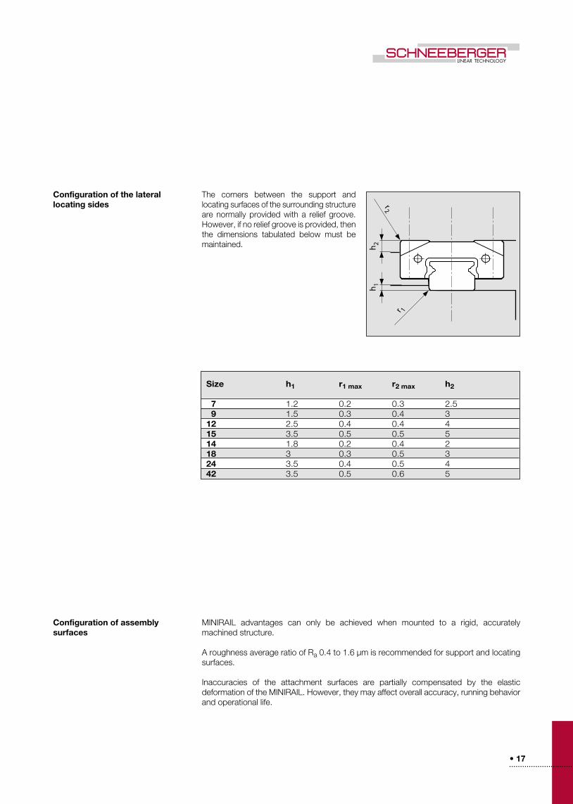
Configuration of the lateral locating sides
Configuration of assemblysurfaces
The corners between the support and locating surfaces of the surrounding structure are normally provided with a relief groove . However, if no relief groove is provided, then the dimensions tabulated below must be maintained .
MINIRAIL advantages can only be achieved when mounted to a rigid, accurately machined structure .
A roughness average ratio of Ra 0 .4 to 1 .6 µm is recommended for support and locating surfaces .
Inaccuracies of the attachment surfaces are partially compensated by the elastic deformation of the MINIRAIL . However, they may affect overall accuracy, running behavior and operational life .
Size h1 r1 max r2 max h2
7 1 .2 0 .2 0 .3 2 .5 9 1 .5 0 .3 0 .4 312 2 .5 0 .4 0 .4 415 3 .5 0 .5 0 .5 514 1 .8 0 .2 0 .4 218 3 0 .3 0 .5 324 3 .5 0 .4 0 .5 442 3 .5 0 .5 0 .6 5
• 18• • • • • • • • • • • • • • • • • • • • • • • • • • • •
E2
K
E1.
1E
1.2
Q
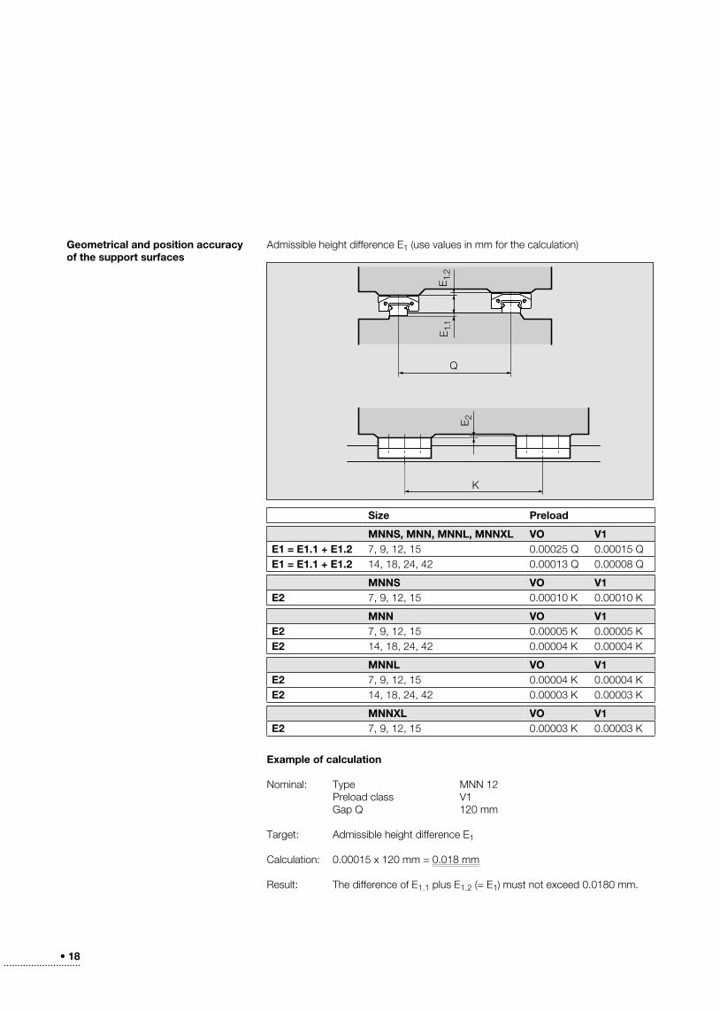
Geometrical and position accuracy of the support surfaces
Admissible height difference E1 (use values in mm for the calculation)
Example of calculation
Nominal: Type MNN 12 Preload class V1 Gap Q 120 mm
Target: Admissible height difference E1
Calculation: 0 .00015 x 120 mm = 0 .018 mm
Result: The difference of E1 .1 plus E1 .2 (= E1) must not exceed 0 .0180 mm .
Size Preload
MNNS, MNN, MNNL, MNNXL VO V1E1 = E1.1 + E1.2 7, 9, 12, 15 0 .00025 Q 0 .00015 QE1 = E1.1 + E1.2 14, 18, 24, 42 0 .00013 Q 0 .00008 Q
MNNS VO V1E2 7, 9, 12, 15 0 .00010 K 0 .00010 K
MNN VO V1E2 7, 9, 12, 15 0 .00005 K 0 .00005 KE2 14, 18, 24, 42 0 .00004 K 0 .00004 K
MNNL VO V1E2 7, 9, 12, 15 0 .00004 K 0 .00004 KE2 14, 18, 24, 42 0 .00003 K 0 .00003 K
MNNXL VO V1E2 7, 9, 12, 15 0 .00003 K 0 .00003 K
• 19• • • • • • • • • • • • • • • • • • • • • • • • • • • • • • • • • • • •
∆
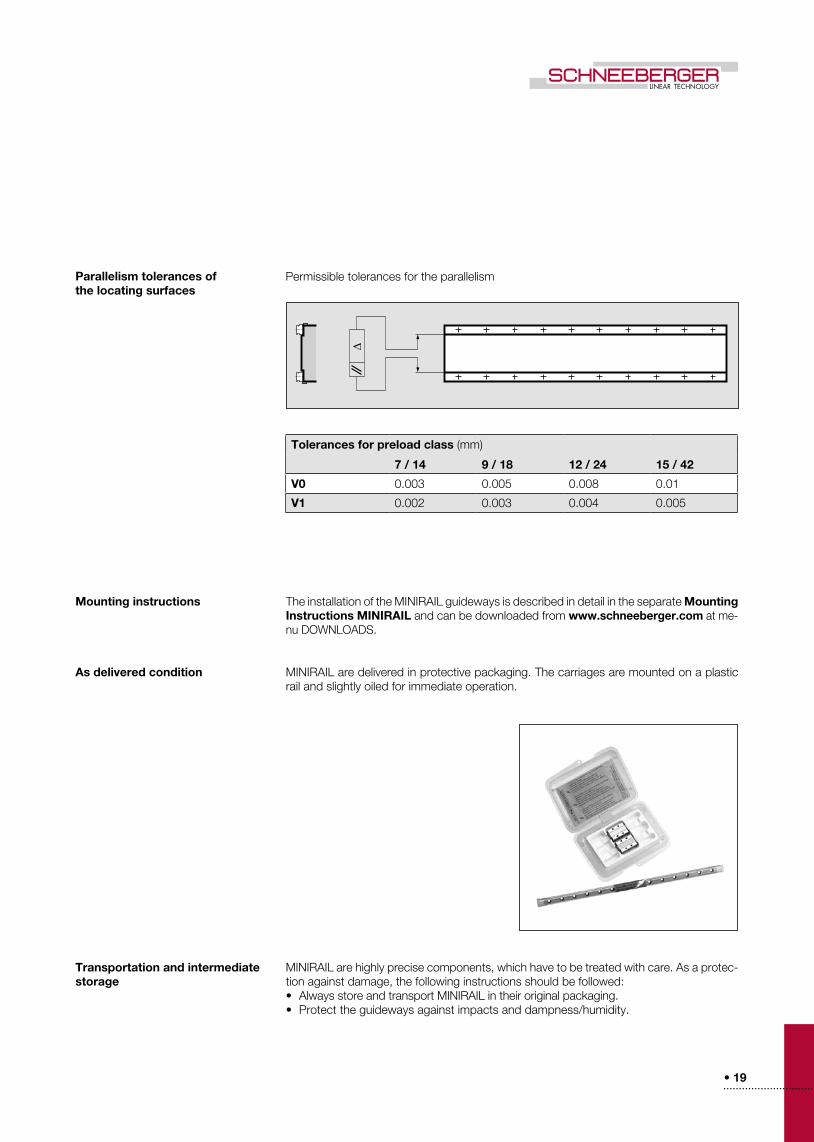
Parallelism tolerances of the locating surfaces
Mounting instructions
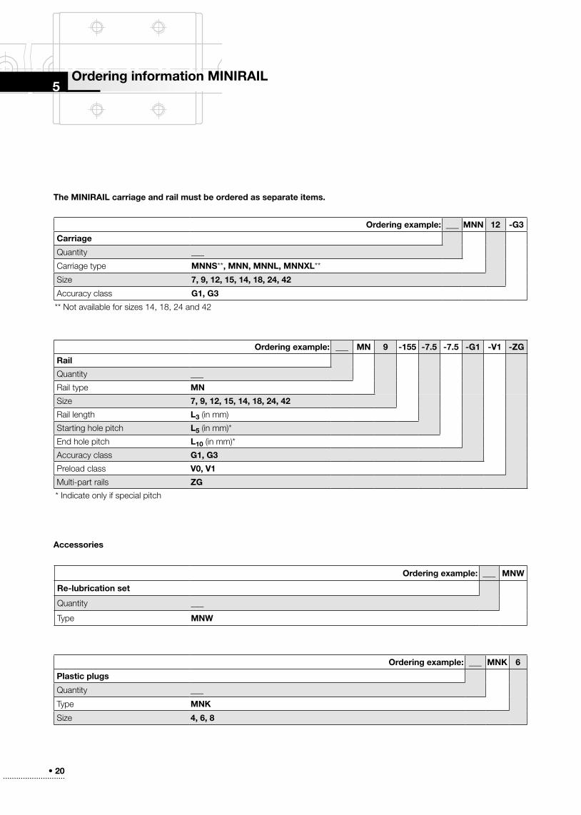
As delivered condition
Transportation and intermediate storage
The installation of the MINIRAIL guideways is described in detail in the separate Mounting Instructions MINIRAIL and can be downloaded from www.schneeberger.com at me-nu DOWNLOADS .
MINIRAIL are delivered in protective packaging . The carriages are mounted on a plastic rail and slightly oiled for immediate operation .
MINIRAIL are highly precise components, which have to be treated with care . As a protec-tion against damage, the following instructions should be followed:• Always store and transport MINIRAIL in their original packaging .• Protect the guideways against impacts and dampness/humidity .
Permissible tolerances for the parallelism
Tolerances for preload class (mm)
7 / 14 9 / 18 12 / 24 15 / 42
V0 0 .003 0 .005 0 .008 0 .01
V1 0 .002 0 .003 0 .004 0 .005
• 20• • • • • • • • • • • • • • • • • • • • • • • • • • • •
5
The MINIRAIL carriage and rail must be ordered as separate items.
Accessories
Ordering information MINIRAIL
Ordering example: ___ MNN 12 -G3
Carriage
Quantity ___
Carriage type MNNS**, MNN, MNNL, MNNXL**
Size 7, 9, 12, 15, 14, 18, 24, 42
Accuracy class G1, G3
Ordering example: ___ MN 9 -155 -7.5 -7.5 -G1 -V1 -ZG
Rail
Quantity ___
Rail type MN
Size 7, 9, 12, 15, 14, 18, 24, 42
Rail length L3 (in mm)
Starting hole pitch L5 (in mm)*
End hole pitch L10 (in mm)*
Accuracy class G1, G3
Preload class V0, V1
Multi-part rails ZG
* Indicate only if special pitch
Ordering example: ___ MNW
Re-lubrication set
Quantity ___
Type MNW
Ordering example: ___ MNK 6
Plastic plugs
Quantity ___
Type MNK
Size 4, 6, 8
** Not available for sizes 14, 18, 24 and 42