Embed Size (px)
Citation preview

Mining Cables

Contents
Introduction _________________________________ 3
Cable Components __________________________ 4
Cable Handling ______________________________ 8
Health, Safety and Environment __________ 9
Quick Reference Guide ____________________ 10
Underground Mining - Coal ________________12
Type 241 and 241SF ____________________________ 14
Type 245SF _____________________________________16
Type 275 ______________________________________ 18
Metalliferous Mining ______________________ 20
Type 241 and 241SF ____________________________ 22
Type 245SF ____________________________________ 24
Type 275 ______________________________________ 26
Feeder Cables ______________________________ 28
11/11kV Paper Insulated ________________________ 30
6.35/11kV Copper ______________________________ 32
12.7/22kV Copper ______________________________ 34
Whilst every care has been taken in the preparation of this publication, the Prysmian Group take no responsibility for any errors and or omissions.
This booklet is intended as a guide only and reference must be made by any person using this booklet to the appropriate Australian/New Zealand
Standard and or to local electricity supply authority rulings. The company reserves the right to make changes in product without notice. All rights
reserved. Subject to change without notice.

3
Introduction
ONE LEADER, TWO BRANDS
The world’s largest cable company, the Prysmian
Group, consists of Prysmian and Draka which are two
of the world’s most respected commercial brands in
the industry. With subsidiaries in 50 countries, almost
100 manufacturing plants, 17 Research & Development
Centres and around 22,000 employees, the Prysmian
Group is truly a global company.
Proudly manufacturing in Australia since 1940, Prysmian
understands local standards and conditions and our
products are designed and developed accordingly.
Prysmian specialises in integrated, added value
cabling solutions highly customised to the individual
specifications of customers. Prysmian operates a
Quality Management System compliant with the
requirements of ISO 9001:2008 and products are fully
supported by the global technical and production
capabilities of the Prysmian Group.
Prysmian understands local
standards and conditions and
our products are designed and
developed accordingly.

4
DEVELOPMENT OF ELASTOMERIC POWER CABLES
FOR SAFE AND RELIABLE MINING AND INDUSTRIAL
APPLICATIONS HAS PARALLELED THE DEVELOPMENT
OF THE ELECTRIC MOTOR AND POWER GENERATION
SINCE THE 19TH CENTURY.
Elastomeric cables are the natural choice for
applications where durability, flexibility, and safe
operation under extreme environmental conditions are
important. The Prysmian Group’s elastomeric cables
have been “field proven” in thousands of operations,
and with continuous development, utilise the best
features of cables offered around the world.
In Australia, as elsewhere, there are many established
guidelines governing manufacture of mining and
industrial cables. Innovation in work practices, with
more equipment operating at higher voltages, has
required the continued development of new elastomeric
cable designs. Ongoing development programs have
also been required to continually improve the reliability
and safety of current designs. The major design
responsibility for the Prysmian Group is to ensure that
cables supplied will operate reliably and safely under a
wide range of conditions. Personnel often work close to
energised cables, especially in underground mines. The
cable construction and materials must be selected to
provide maximum safety during both normal operation
and in the case of cable failure.
CONDUCTORS
The important flexibility, strength and electrical
properties of mining and industrial cables are mainly
derived from the particular conductor design used,
and any armouring or reinforcement. Conductors used
in these cables are to Australian and International
Standards, and usually employ tinned annealed copper
wires stranded to provide optimum flexibility. Flexibility
is influenced by the number of individual wires for a
given size, the lay length of bunches and strands, and
the geometric arrangement of the strands.
Cable Components

5
A simple examination of wires and their size is not a
reliable guide to their flexibility or endurance, since
special designs are often developed to suit particular
applications. These would include cables for heavy-duty
reeling or flexing such as ship-loader or longwall shearer
applications. The use of specially designed power, earth
or pilot conductors, and their locations in the cable
provide a good example of this.
CORE ASSEMBLY LAY LENGTH
This is a vital factor affecting cable life when the cable is
subjected to repeated reeling, especially under tension.
A ratio of cable lay length (pitch) to pitch circle diameter
(the diameter of a circle passing through the mid points
of the cores) is commonly used to specify lay lengths
suited to various applications. For moderate duty reeling
cables, this value should be less than 12.5, and for
trailing cables it should be less than 17.
CABLE COMPONENTS

6
CABLE COMPONENTS
INSULATION
In the past fifty years, natural rubber insulation has
been replaced by synthetic polymeric compounds with
inherently superior properties. Ethylene-propylene
copolymer (EPR) and terpolymer (EPDM) are most
common on flexible cables, offering excellent
thermal durability, corona resistance, and electrical
characteristics. Cross linked polyethylene (XLPE)
insulation has found limited use in fixed applications.
Insulation materials are chosen for optimum dielectric
characteristics, and resistance to deterioration through
heat, oxidation, salts and copper compounds. Inert
fillers are used for maximum electrical stability and low
moisture absorption.
PILOT
The resistance between mining equipment and earth
is usually high, and dangerous voltages can be present.
To prevent hazards from shock, ground fault currents
are controlled by various systems, including neutral
resistance grounding. To ensure the integrity of this
safety circuit, a small independent current may be
passed through a pilot conductor to the load centre and
return through the earth conductor. If this current is
interrupted through breakage, then the circuit breaker
will automatically trip and remove power from the cable.
Australian mining regulatory authorities require the
inclusion of an extensible central pilot conductor (for
monitoring circuit integrity). This is specially designed
and manufactured to restrict extensibility in service. The
cores of each underground coal mining cable must also
be electrically symmetrical for added safety.
SCREENS
Bending of conductors under tension accelerates
the breakage of individual wires. Partial failure of
conductors can lead to wire ends that penetrate through
the insulation. Metallic screens over the power cores, or
earthing cores associated with semiconductive rubber
components are provided to ground such faults through
an earth. Besides being part of the earth fault detection
circuit, screens relieve non-uniform electrical stresses
and provide a uniform capacitance to ground.

7
CABLE COMPONENTS
Screening is achieved by either a helically applied layer
of wires, a composite textile and tinned copper wire
braid, semi-conductive elastomer, or a combination of
the latter. Medium voltage reeling and trailing cables
usually have either individually core composite textile
/ copper braid or semiconductive rubber screens for
minimal fatigue failure. Collective screens of either
semiconductive rubber, braids, or pliable steel wire
armour with copper wires to achieve the desired
conductivity may also be used. The latter types are
used in cable constructions for fixed or feeder cable
applications.
Semiconductive rubber screens are used in cables
connected to systems which are able to limit earth
faults to around 500 mA (r.m.s.) within about 10ms.
Australian cables have fire propagation resistant
semiconductive screens.
ARMOUR & REINFORCEMENT
Prysmian Group trailing cables manufactured to AS/NZS
1802 and AS/NZS 2802 and subjected to harsh wear,
employ nylon textile or woven polyester tape, or an open
braid of Kevlar® fibre as reinforcement. This enhances
the sheath’s mechanical strength, and improves the
resistance against damage from crushing, stretching,
and tear propagation.
Where a very high degree of impact and cut resistance is
required, designs will usually have a pliable wire armour.
This makes the cable much heavier and more difficult
to handle and use. Heavy duty textile reinforcement is
preferred form an operational point of view.
SHEATH
The primary role of the cable sheath is to protect the
underlying core assembly from mechanical, chemical,
or other environmental damage. Polychloroprene (PCP),
chlorosulphonated polyethylene (CSP), and chlorinated
polyethylene (CPE) are the most commonly used
synthetic polymers used in sheaths today. They are
commonly filled with other materials to enhance sheath
performance.
A properly formulated sheathing compound is essential
for a high performance reeling or trailing cable. The
higher the tensile strength, the stronger the material
is when stretched. As the material gets hotter, tensile
strength reduces with a consequent reduction in tear
resistance. As cables age, elongation may be reduced
(the material becomes brittle).

8
Cable Handling
MINIMUM BENDING
RADIUS DURING
INSTALLATION
MINIMUM
INSTALLATION
TEMPERATURE
INTERNAL
WIRING
IN FREE AIR
INDUSTRIAL
EQUIPMENT
IN GROUND WITH
PROTECTION
EXTERNAL
BUILDING
IN TRENCH IN GROUND IN DUCT DOMESTIC
APPLIANCES
MACHINES
MOBILE
EQUIPMENT
IN CONDUIT
SUBMERGED
OUTDOOR
APPLIANCES
OVERHEAD AERIAL
FESTOON
AMBIENT TEMPERATURE
Maximum continuous conductor temperature
Minimum continuous conductor temperature
HALOGEN FREE
Halogen free (toxic fume or corrosives) cables
MINIMUM BENDING RADIUS
Minimum bending radius of installed cables
MECHANICAL IMPACT RESISTANCE
1 Light Impact
2 Moderate Impact
3 Heavy Impact
4 Very Heavy Impact
RESISTANCE TO SOLAR RADIATION AND WEATHER
Excellent Permanent
Very Good Frequent
Good Occasional
Acceptable Accidental
Poor None
FLEXIBILITY
Rigid Flexible
Semi-rigid Very flexible
CHEMICAL RESISTANCE
Excellent Permanent
Very Good Frequent
Good Occasional
Acceptable Accidental
Poor None
BEHAVIOUR IN FLAME AND FIRE
Reaction To Fire Resistant To Fire
C 1 Fire retardant CR 1 Fire resistant
C 2 Flame retardant CR 2 All non CR 1 cables
C 3 No fire performance
RESISTANCE TO WATER
Negligible No humidity
Water Drops Occasional condensation
Spray Water run off
Splashes Exposed to water splashes
Heavy Sea Exposed to waves
Immersion Temporarily covered by water
Submersion Permanently covered by water
Cable Usage Characteristics
Laying Conditions

9
PEOPLE ARE OUR GREATEST ASSET. WE BELIEVE
EVERYONE HAS THE RIGHT TO WORK AND LIVE IN A
HEALTHY AND SAFE ENVIRONMENT.
The Prysmian Group maintains our commitment to
comply with all relevant Occupational Health, Safety and
Environmental legislation, Australian and New Zealand
Standards (AS/NZS 4801 and ISO 14001) Licences and
Industry Codes of Practices.
Our goal is an environmentally and socially sustainable
business and we believe that a safe work environment
is a sign of efficiency and quality. Accidents can be
prevented and we commit to continually improve, to
achieve zero incidents of work related injury, illness and
environmental pollution.
We also aim to help our customers fulfil their
environmental responsibilities by providing them with
cables and associated products that we believe have
been manufactured as efficiently, economically sound
and environmentally sustainable as possible. As our
products are locally designed and manufactured we
recognize the importance of risk assessment and
mitigation in all mining operations.
For additional support in this area we have dedicated
technical staff available to provide specific product
information and guidelines for use please contact:
Health, Safety and Environment

10
Quick Reference Guide
Standard CodeH
V F
eede
r
Sect
ion
Pow
er
Ligh
ting
Pow
er T
ools
Cutt
er M
otor
Conv
eyor
Dri
ve
Long
wal
l Pow
er
Long
wal
l She
arer
Roo
f B
olte
r
Mul
e
Shut
tle
Car
210.1
209.1
209.3
240.1
240.3
240.11
241.1
241.3
241.11
245.1
245.3
260.1
260.3
260.11
275.1
Type 1
Type 2S
Type A
Type B
409
412
440
441
450
451
455
450M

11
Cont
inuo
us M
iner
Roa
d H
eade
r
Load
er
Cont
inuo
us H
aula
ge
Ven
tila
tion
Fan
Dri
ll R
ig
Face
Sho
vel
Buc
ket
Whe
el
Dra
glin
e
Pum
p
Dre
dge
Stac
ker -
Rec
laim
er
Ship
Loa
der
Cont
aine
r Cra
ne
LEGEND: Recommended Suitable

Underground Mining - Coal“ELECTRIC CABLES IN UNDERGROUND COAL MINE HAZARDOUS
ZONES ARE SUBJECT TO AN EXTREMELY ARDUOUS ENVIRONMENT
THAT IS OFTEN VERY WET. IN ADDITION, THEY ARE HANDLED
REGULARLY BY MINE WORKERS WHILE ENERGISED.”
- NSW Government Industry & Investment. Technical Report EES-100.
Electrical Engineering Safety Underground Coal Mine. Electric Cables used in Hazardous Zones

Australian and New Zealand coal mines are some of the safest in the world. This safety record is built on strict
controls and legislation to ensure that the cables for mining equipment and in particularly those used in
hazardous areas are of particularly high quality.
Our cables listed in this section are compliant with the relevant standards for the differently classified zones of an
underground coal mine, including AS/NZS 1802, AS/NZS 1972 and AS/NZS 5000.1. Prysmian cables manufactured to
these standards have a proven track record of safe and reliable performance in the harsh environments that exist in
underground mines.
We understand that a longwall mining operation may have very different demands on cable performance to a board
and pillar or hydraulic monitor operation and our range is tailored to suit the specific challenges that varied mining
operations present.

14
UNDERGROUND MINING - COAL
Type 241
and 241SF
SEMICONDUCTIVE SCREENED CABLE FOR GENERAL USE TO AS/NZS 1802
These cables have been designed to operate within the tight bending radii experienced with cable chains used on
longwall shearers, and provide additional pilot conductors for modern machine monitoring.
Semiconductive screened power cores, with three earth cones and one extensible pilot. General purpose cable for
continuous miners, or feeder cables to pumps. Also commonly used for monorails supplying DCBs and longwalls. Type
241SF cable has special stranding and lay-up. PED ratio to provide maximum flexibility in arduous conditions.
Type 241SF cable designed for applications
requiring maximum flexibility.
Cable Characteristics
Installation Conditions
Cable Design
CORE:
Metal: Tinned Copper, 3 core 3 earths plus central pilot
Flexibility: Very flexible for Type 241SF cable
Maximum Continuous Operating Temperature: 90˚C
Conductor Separator Type: 1.1/1.1kV - polyester where necessary
3.3kV and above - semiconductive screen
INSULATION:
EPR (R-EP-90) core with durably printed core numbers at intervals less than 300mm, on black semiconductive
insulation screen for phase identification
SCREEN:
Semiconductive elastomer screen
PILOT:
Single, in centre of cable. Max. D.C. resistance of 5.5 Ω/100m for power cores to 35mm2, and 3 Ω/100m for power
conductors above 35mm2
EARTH:
Three semiconductive elastomer covered flexible earths, located in the interstices
SHEATH:
Open weave reinforcement, under heavy duty HD-85-PCP
+90˚C
-25˚C
IN FREE AIR IN DUCT MOBILE
EQUIPMENT
MACHINES
3 Excellent Immersion Very Good C1 V. Flexible
Central
Pilot Core
Semi
conductive
Elastomer
Screen
HD
Elastomer
SheathEarth Core
Numbered
Phase core

15
Physical Characteristics
Electrical Characteristics
Cable Type 241 241 241 241 241 241 241SF 241
Prysmian Part Number 5013597 5014150 5013078 5013627 5013191 5052343 5023237 5029697
Phase Core:
Cross Sectional Area (Nominal) mm2 35 50 95 120 150 185 120 150
Conductor Wire Diameter (Nominal) mm 0.30 0.30 0.50 0.50 0.50 0.50 0.50 0.50
Conductor Diameter (Nominal) mm 8.4 9.7 13.3 15.3 17.2 18.8 15.6 17.2
Insulation Thickness (Minimum Average) mm 1.6 1.7 2.0 2.1 2.3 2.5 3.0 3.0
Sheath Thickness (Minimum Average) mm 4.4 4.9 5.8 6.3 6.7 7.3 7.2 7.6
Overall Cable Diameter (Approx.) mm 41.9 46.2 57.0 62.8 68.5 74.3 69.9 74.1
Cable Weight (Approx.): kg/m 3.09 3.82 6.05 7.46 9.09 10.8 9.04 10.3
Maximum Pulling Tension:
Cable subjected to repeated reeling or
bending whilst under tensionkN 1.58 2.25 4.28 5.40 6.75 8.33 5.40 6.75
Cable subjected to straight pull,
i.e. without significant bending or flexingkN 3.15 4.50 8.55 10.8 13.5 16.7 10.8 13.5
Minimum Bending Radius:
For Fixed Bend mm 170 185 230 250 275 295 420 445
For Free Flexing Applications mm 250 275 340 375 410 445 700 740
For Permanent Repeated Reeling mm 420 460 570 630 685 745 840 890
For Passing Over Sheaves mm 420 460 570 630 685 745 1050 1110
Cable Type 241 241 241 241 241 241 241SF 241
Prysmian Part Number 5013597 5014150 5013078 5013627 5013191 5052343 5023237 5029697
Rated Voltage (Uo/U) kV 1.1/1.1 1.1/1.1 1.1/1.1 1.1/1.1 1.1/1.1 1.1/1.1 3.3/3.3 3.3/3.3
Maximum Resistance:
Phase Conductor, dc Ω/km @20°C 0.547 0.410 0.212 0.164 0.129 0.106 0.164 0.129
Phase Conductor, ac @ 50Hz Ω/km @90°C 0.698 0.523 0.271 0.210 0.166 0.136 0.210 0.165
Earth Conductor (Combined), dc Ω/km @20°C 1.64 1.23 0.547 0.492 0.387 0.318 0.328 0.258
Pilot Conductor, dc Ω/km @20°C 55 30 30 30 30 30 30 30
Inductance mH/km 0.397 0.384 0.357 0.345 0.338 0.334 0.368 0.356
Inductive Reactance Ω/km 0.125 0.120 0.112 0.108 0.106 0.105 0.116 0.112
Capacitance (Phase to earth) μF/km 0.474 0.510 0.585 0.634 0.649 0.655 0.516 0.558
3-Phase Voltage Drop mV/A.m 1.23 0.930 0.508 0.409 0.341 0.298 0.415 0.346
3-Phase Symmetrical Fault Rating kA for 1sec 5.01 7.15 13.6 17.2 21.5 26.5 17.2 21.5
Continuous Current Rating*:
Cable Protected From Sun A 145 170 250 295 340 385 295 340
Cable Exposed To Sun
(Solar intensity = 1000W/m)A 110 125 185 210 245 270 220 240
Type 241
and 241SF
Type 241
and 241SF
*In accordance with AS/NZS2802 for single cable in free air condition based on a conductor temperature of 90°C and an ambient air temperature
of 40°C. Must consider derating or rating factor(s) for other conditions.
UNDERGROUND MINING - COAL

16
Type 245SF
SUPER FLEXIBLE CABLE FOR GENERAL USE TO AS/NZS 1802
These cables have been designed to operate within the tight bending radii experienced with cable chains used on
longwall shearers, and provide additional pilot conductors for modern machine monitoring.
Semiconductive screened power cores, with three earth cores and three extensible pilots for general purpose, and
especially for trailing applications in cable chains on Longwall Shearer equipment, and in environments calling for
maximum flexibility.
Cables designed for applications requiring
maximum flexibility.
Cable Characteristics
Installation Conditions
Cable Design
CORE:
Metal: Tinned Copper, 3 core 3 earths plus 3 central pilots
Flexibility: Very flexible
Maximum Continuous Operating Temperature: 90˚C
Conductor Separator Type: 3.3kV - semiconductive screen
INSULATION:
EPR (R-EP-90) core with durably printed core numbers at intervals less than 300mm, on black semiconductive
insulation screen for phase identification
SCREEN:
Semiconductive elastomer screen
PILOT:
3 pilots, in the centre of the cable. Max. D.C. resistance of 3 Ω/100m for all cables
EARTH:
Three semiconductive elastomer covered flexible earths, located in the interstices
SHEATH:
Open weave reinforcement, under heavy duty HD-85-PCP
+90˚C
-25˚C
IN FREE AIR IN DUCT MOBILE
EQUIPMENT
MACHINES
3 Excellent Immersion Very Good C1 V. Flexible
Central Pilot/
Control Cores
HD
Elastomer
SheathEarth Cores
Numbered
Phase Core
UNDERGROUND MINING - COAL

17
Physical Characteristics
Electrical Characteristics
Cable Type 245SF 245SF
Prysmian Part Number 5014921 5023220
Phase Core:
Cross Sectional Area (Nominal) mm 70 95
Conductor Wire Diameter (Nominal) mm 0.30 0.30
Conductor Diameter (Nominal) mm 12.2 13.8
Insulation Thickness (Minimum Average) mm 3.0 3.0
Sheath Thickness (Minimum Average) mm 6.0 6.4
Overall Cable Diameter (Approx.) mm 62.5 66.5
Cable Weight (Approx.): kg/m 6.78 7.91
Maximum Pulling Tension:
Cable subjected to repeated reeling or bending whilst under tension kN 3.15 4.28
Cable subjected to straight pull, i.e. without significant bending or flexing kN 6.30 8.55
Minimum Bending Radius:
For Fixed Bend mm 375 400
For Free Flexing Applications mm 625 665
For Permanent Repeated Reeling mm 750 800
For Passing Over Sheaves mm 940 1000
Cable Type 245SF 245SF
Prysmian Part Number 5014921 5023220
Rated Voltage (Uo/U) kV 3.3/3.3 3.3/3.3
Maximum Resistance:
Phase Conductor, dc Ω/km @20°C 0.271 0.212
Phase Conductor, ac @ 50Hz Ω/km @90°C 0.346 0.271
Earth Conductor (Combined), dc Ω/km @20°C 0.542 0.424
Pilot Conductor, dc Ω/km @20°C 30 30
Inductance mH/km 0.412 0.394
Inductive Reactance Ω/km 0.129 0.124
Capacitance (Phase to earth) μF/km 0.387 0.427
3-Phase Voltage Drop mV/A.m 0.640 0.516
3-Phase Symmetrical Fault Rating kA for 1sec 10.0 13.6
Continuous Current Rating*:
Cable Protected From Sun A 220 250
Cable Exposed To Sun (Solar intensity = 1000W/m) A 155 180
Type 245SF
Type 245SF
*In accordance with AS/NZS2802 for single cable in free air condition based on a conductor temperature of 90°C and an ambient air temperature
of 40°C. Must consider derating or rating factor(s) for other conditions.
UNDERGROUND MINING - COAL

18
Type 275
SHUTTLE CAR CABLE TO AS/NZS 1802
These cables are used with high-speed reeling equipment employed on shuttle cars, and are subject to the greatest
exertion underground. Cable constructions are designed to resist “corkscrewing” in these arduous conditions.
Non-individually screened power cores, three earth cores and one extensible pilot, laid-up in a semiconductive
cradle and fill to 1.1/1.1kV application.
Cable Characteristics
Cable Design
CORE:
Metal: Tinned Copper, 3 core 3 earths plus pilot
Maximum Continuous Operating Temperature: 90˚C
INSULATION:
EPR (R-EP-90) Core Colours Red, White, Blue
PILOT:
1 pilot, in the centre of the cable. Max. D.C. resistance of 5.5 Ω/100m for power conductors up to 35mm2,
and 3 Ω/100m for all larger cables
EARTH:
Three semiconductive elastomer covered flexible earths, located in the interstices
SHEATH:
Semiconductive elastomer filled, with an open weave reinforcement, under a heavy duty HD-85-PCP
+90˚C
-25˚C
3 Excellent Immersion Very Good C1 Flexible
Central Pilot
Core
Earth Core
Coloured
Phase Core
Installation Conditions
HD
Elastomer
Sheath
IN FREE AIR MOBILE
EQUIPMENT
UNDERGROUND MINING - COAL

19
Physical Characteristics
Electrical Characteristics
Cable Type 275 275
Prysmian Part Number 5012705 5015065
Phase Core:
Cross Sectional Area (Nominal) mm 35 50
Conductor Wire Diameter (Nominal) mm 0.40 0.40
Conductor Diameter (Nominal) mm 8.9 10.2
Insulation Thickness (Minimum Average) mm 1.6 1.7
Sheath Thickness (Minimum Average) mm 4.3 4.7
Overall Cable Diameter (Approx.) mm 38.9 43.2
Cable Weight (Approx.): kg/m 2.94 3.68
Maximum Pulling Tension:
Cable subjected to repeated reeling or bending whilst under tension kN 1.58 2.25
Cable subjected to straight pull, i.e. without significant bending or flexing kN 3.15 4.50
Minimum Bending Radius:
For Fixed Bend mm 155 175
For Free Flexing Applications mm 235 260
For Permanent Repeated Reeling mm 390 430
For Passing Over Sheaves mm 390 430
Cable Type 275 275
Prysmian Part Number 5012705 5015065
Rated Voltage (Uo/U) kV 1.1/1.1 1.1/1.1
Maximum Resistance:
Phase Conductor, dc Ω/km @20°C 0.547 0.410
Phase Conductor, ac @ 50Hz Ω/km @90°C 0.698 0.523
Earth Conductor (Combined), dc Ω/km @20°C 1.64 1.23
Pilot Conductor, dc Ω/km @20°C 55 30
Inductance mH/km 0.351 0.343
Inductive Reactance Ω/km 0.110 0.108
Capacitance (Phase to earth) μF/km 0.502 0.535
3-Phase Voltage Drop mV/A.m 1.22 0.925
3-Phase Symmetrical Fault Rating kA for 1sec 5.01 7.15
Continuous Current Rating*:
Cable Protected From Sun A 145 170
Cable Exposed To Sun (Solar intensity = 1000W/m) A 110 125
Type 275
Type 275
*In accordance with AS/NZS2802 for single cable in free air condition based on a conductor temperature of 90°C and an ambient air temperature
of 40°C. Must consider derating or rating factor(s) for other conditions.
UNDERGROUND MINING - COAL
Metalliferous Mining“AS THIS TYPE OF PLANT PRESENTS A HIGH RISK IN RELATION TO
ELECTROCUTION, FIRES AND EXPLOSIONS, THE ASSESSMENT OF
CABLES AND ANY ASSOCIATED COMPLIANCE STATEMENT NEEDS TO
BE HIGHLY CREDIBLE.”
- NSW Department of Primary Industry. Electrical Engineering Safety Decision Sheet 7.1.
Evidence of compliance to Standards. Cables for use in hazardous zones

Hard rock or metalliferous mining employs very different mining techniques to that of coal and surface mining.
Often exposed to extremes in temperature and longer life cycles when commissioned the cables used in these
applications have specific performance requirements.
Compact and light weight design, ultra durable, easy to terminate and repair our hard rock range is designed with
consideration for the special requirements which are presented by highly demanding geographically isolated work
environments.

22
METALLIFEROUS MINING
SEMICONDUCTIVE SCREENED CABLE FOR GENERAL USE TO AS/NZS 1802
These cables have been designed to operate within the tight bending radii experienced with cable chains used on
longwall shearers, and provide additional pilot conductors for modern machine monitoring.
Semiconductive screened power cores, with three earth cones and one extensible pilot. General purpose cable for
continuous miners, or feeder cables to pumps. Also commonly used for monorails supplying DCBs and longwalls. Type
241SF cable has special stranding and lay-up. PED ratio to provide maximum flexibility in arduous conditions.
Type 241SF cable designed for applications
requiring maximum flexibility.
Cable Characteristics
Installation Conditions
Cable Design
CORE:
Metal: Tinned Copper, 3 core 3 earths plus central pilot
Flexibility: Very flexible for Type 241SF cable
Maximum Continuous Operating Temperature: 90˚C
Conductor Separator Type: 1.1/1.1kV - polyester where necessary
3.3kV and above - semiconductive screen
INSULATION:
EPR (R-EP-90) core with durably printed core numbers at intervals less than 300mm, on black semiconductive
insulation screen for phase identification
SCREEN:
Semiconductive elastomer screen
PILOT:
Single, in centre of cable. Max. D.C. resistance of 5.5 Ω/100m for power cores to 35mm2, and 3 Ω/100m for power
conductors above 35mm2
EARTH:
Three semiconductive elastomer covered flexible earths, located in the interstices
SHEATH:
Open weave reinforcement, under heavy duty HD-85-PCP
+90˚C
-25˚C
IN FREE AIR IN DUCT MOBILE
EQUIPMENT
MACHINES
3 Excellent Immersion Very Good C1 V. Flexible
Type 241
and 241SFCentral
Pilot Core
Semi
conductive
Elastomer
Screen
HD
Elastomer
SheathEarth Core
Numbered
Phase core

23
Physical Characteristics
Electrical Characteristics
Cable Type 241 241 241 241 241 241 241SF 241
Prysmian Part Number 5013597 5014150 5013078 5013627 5013191 5052343 5023237 5029697
Phase Core:
Cross Sectional Area (Nominal) mm 35 50 95 120 150 185 120 150
Conductor Wire Diameter (Nominal) mm 0.30 0.30 0.50 0.50 0.50 0.50 0.50 0.50
Conductor Diameter (Nominal) mm 8.4 9.7 13.3 15.3 17.2 18.8 15.6 17.2
Insulation Thickness (Minimum Average) mm 1.6 1.7 2.0 2.1 2.3 2.5 3.0 3.0
Sheath Thickness (Minimum Average) mm 4.4 4.9 5.8 6.3 6.7 7.3 7.2 7.6
Overall Cable Diameter (Approx.) mm 41.9 46.2 57.0 62.8 68.5 74.3 69.9 74.1
Cable Weight (Approx.): kg/m 3.09 3.82 6.05 7.46 9.09 10.8 9.04 10.3
Maximum Pulling Tension:
Cable subjected to repeated reeling or
bending whilst under tensionkN 1.58 2.25 4.28 5.40 6.75 8.33 5.40 6.75
Cable subjected to straight pull,
i.e. without significant bending or flexingkN 3.15 4.50 8.55 10.8 13.5 16.7 10.8 13.5
Minimum Bending Radius:
For Fixed Bend mm 170 185 230 250 275 295 420 445
For Free Flexing Applications mm 250 275 340 375 410 445 700 740
For Permanent Repeated Reeling mm 420 460 570 630 685 745 840 890
For Passing Over Sheaves mm 420 460 570 630 685 745 1050 1110
Cable Type 241 241 241 241 241 241 241SF 241
Prysmian Part Number 5013597 5014150 5013078 5013627 5013191 5052343 5023237 5029697
Rated Voltage (Uo/U) kV 1.1/1.1 1.1/1.1 1.1/1.1 1.1/1.1 1.1/1.1 1.1/1.1 3.3/3.3 3.3/3.3
Maximum Resistance:
Phase Conductor, dc Ω/km @20°C 0.547 0.410 0.212 0.164 0.129 0.106 0.164 0.129
Phase Conductor, ac @ 50Hz Ω/km @90°C 0.698 0.523 0.271 0.210 0.166 0.136 0.210 0.165
Earth Conductor (Combined), dc Ω/km @20°C 1.64 1.23 0.547 0.492 0.387 0.318 0.328 0.258
Pilot Conductor, dc Ω/km @20°C 55 30 30 30 30 30 30 30
Inductance mH/km 0.397 0.384 0.357 0.345 0.338 0.334 0.368 0.356
Inductive Reactance Ω/km 0.125 0.120 0.112 0.108 0.106 0.105 0.116 0.112
Capacitance (Phase to earth) μF/km 0.474 0.510 0.585 0.634 0.649 0.655 0.516 0.558
3-Phase Voltage Drop mV/A.m 1.23 0.930 0.508 0.409 0.341 0.298 0.415 0.346
3-Phase Symmetrical Fault Rating kA for 1sec 5.01 7.15 13.6 17.2 21.5 26.5 17.2 21.5
Continuous Current Rating*:
Cable Protected From Sun A 145 170 250 295 340 385 295 340
Cable Exposed To Sun
(Solar intensity = 1000W/m)A 110 125 185 210 245 270 220 240
Type 241
and 241SF
Type 241
and 241SF
*In accordance with AS/NZS2802 for single cable in free air condition based on a conductor temperature of 90°C and an ambient air temperature
of 40°C. Must consider derating or rating factor(s) for other conditions.
METALLIFEROUS MINING

24
METALLIFEROUS MINING
SUPER FLEXIBLE CABLE FOR GENERAL USE TO AS/NZS 1802
These cables have been designed to operate within the tight bending radii experienced with cable chains used on
longwall shearers, and provide additional pilot conductors for modern machine monitoring.
Semiconductive screened power cores, with three earth cores and three extensible pilots for general purpose, and
especially for trailing applications in cable chains on Longwall Shearer equipment, and in environments calling for
maximum flexibility.
Cables designed for applications requiring
maximum flexibility.
Cable Characteristics
Installation Conditions
Cable Design
CORE:
Metal: Tinned Copper, 3 core 3 earths plus 3 central pilots
Flexibility: Very flexible
Maximum Continuous Operating Temperature: 90˚C
Conductor Separator Type: 3.3kV - semiconductive screen
INSULATION:
EPR (R-EP-90) core with durably printed core numbers at intervals less than 300mm, on black semiconductive
insulation screen for phase identification
SCREEN:
Semiconductive elastomer screen
PILOT:
3 pilots, in the centre of the cable. Max. D.C. resistance of 3 Ω/100m for all cables
EARTH:
Three semiconductive elastomer covered flexible earths, located in the interstices
SHEATH:
Open weave reinforcement, under heavy duty HD-85-PCP
+90˚C
-25˚C
IN FREE AIR IN DUCT MOBILE
EQUIPMENT
MACHINES
3 Excellent Immersion Very Good C1 V. Flexible
Type 245SFCentral Pilot/
Control Cores
HD
Elastomer
SheathEarth Cores
Numbered
Phase Core

25
Physical Characteristics
Electrical Characteristics
Cable Type 245SF 245SF
Prysmian Part Number 5014921 5023220
Phase Core:
Cross Sectional Area (Nominal) mm 70 95
Conductor Wire Diameter (Nominal) mm 0.30 0.30
Conductor Diameter (Nominal) mm 12.2 13.8
Insulation Thickness (Minimum Average) mm 3.0 3.0
Sheath Thickness (Minimum Average) mm 6.0 6.4
Overall Cable Diameter (Approx.) mm 62.5 66.5
Cable Weight (Approx.): kg/m 6.78 7.91
Maximum Pulling Tension:
Cable subjected to repeated reeling or bending whilst under tension kN 3.15 4.28
Cable subjected to straight pull, i.e. without significant bending or flexing kN 6.30 8.55
Minimum Bending Radius:
For Fixed Bend mm 375 400
For Free Flexing Applications mm 625 665
For Permanent Repeated Reeling mm 750 800
For Passing Over Sheaves mm 940 1000
Cable Type 245SF 245SF
Prysmian Part Number 5014921 5023220
Rated Voltage (Uo/U) kV 3.3/3.3 3.3/3.3
Maximum Resistance:
Phase Conductor, dc Ω/km @20°C 0.271 0.212
Phase Conductor, ac @ 50Hz Ω/km @90°C 0.346 0.271
Earth Conductor (Combined), dc Ω/km @20°C 0.542 0.424
Pilot Conductor, dc Ω/km @20°C 30 30
Inductance mH/km 0.412 0.394
Inductive Reactance Ω/km 0.129 0.124
Capacitance (Phase to earth) μF/km 0.387 0.427
3-Phase Voltage Drop mV/A.m 0.640 0.516
3-Phase Symmetrical Fault Rating kA for 1sec 10.0 13.6
Continuous Current Rating*:
Cable Protected From Sun A 220 250
Cable Exposed To Sun (Solar intensity = 1000W/m) A 155 180
Type 245SF
Type 245SF
*In accordance with AS/NZS2802 for single cable in free air condition based on a conductor temperature of 90°C and an ambient air temperature
of 40°C. Must consider derating or rating factor(s) for other conditions.
METALLIFEROUS MINING
26
METALLIFEROUS MINING
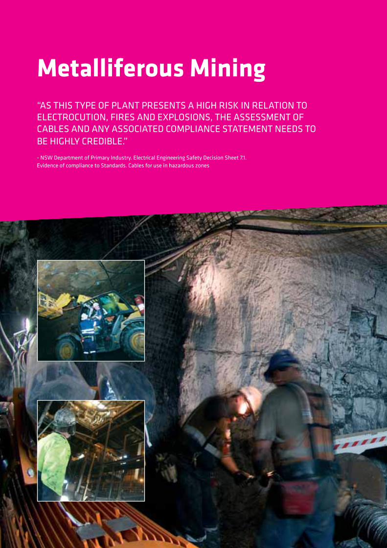
Type 275
SHUTTLE CAR CABLE TO AS/NZS 1802
These cables are used with high-speed reeling equipment employed on shuttle cars, and are subject to the greatest
exertion underground. Cable constructions are designed to resist “corkscrewing” in these arduous conditions.
Non-individually screened power cores, three earth cores and one extensible pilot, laid-up in a semiconductive
cradle and fill to 1.1/1.1kV application.
Cable Characteristics
Cable Design
CORE:
Metal: Tinned Copper, 3 core 3 earths plus pilot
Maximum Continuous Operating Temperature: 90˚C
INSULATION:
EPR (R-EP-90) Core Colours Red, White, Blue
PILOT:
1 pilot, in the centre of the cable. Max. D.C. resistance of 5.5 Ω/100m for power conductors up to 35mm2,
and 3 Ω/100m for all larger cables
EARTH:
Three semiconductive elastomer covered flexible earths, located in the interstices
SHEATH:
Semiconductive elastomer filled, with an open weave reinforcement, under a heavy duty HD-85-PCP
+90˚C
-25˚C
3 Excellent Immersion Very Good C1 Flexible
Pilot core
Earth core
Coloured
phase core
Installation Conditions
HD sheath
IN FREE AIR MOBILE
EQUIPMENT
27
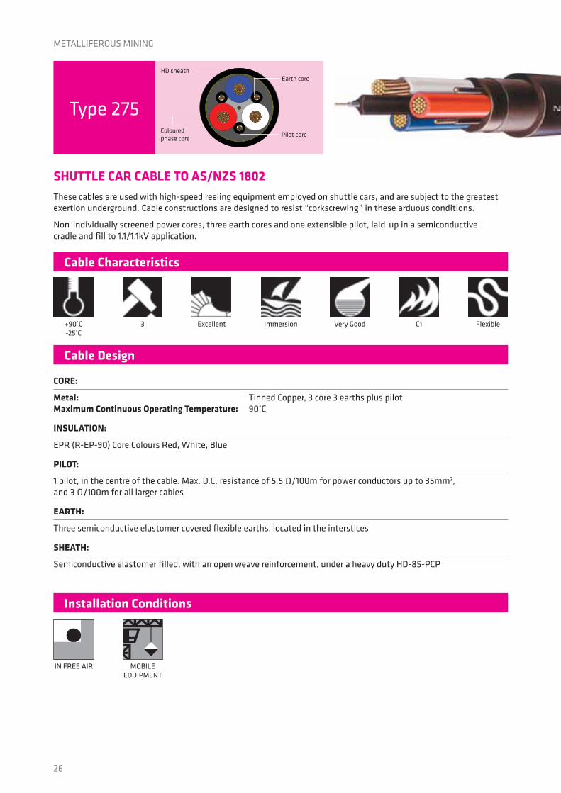
Physical Characteristics
Electrical Characteristics
Cable Type 275 275
Prysmian Part Number 5012705 5015065
Phase Core:
Cross Sectional Area (Nominal) mm 35 50
Conductor Wire Diameter (Nominal) mm 0.40 0.40
Conductor Diameter (Nominal) mm 8.9 10.2
Insulation Thickness (Minimum Average) mm 1.6 1.7
Sheath Thickness (Minimum Average) mm 4.3 4.7
Overall Cable Diameter (Approx.) mm 38.9 43.2
Cable Weight (Approx.): kg/m 2.94 3.68
Maximum Pulling Tension:
Cable subjected to repeated reeling or bending whilst under tension kN 1.58 2.25
Cable subjected to straight pull, i.e. without significant bending or flexing kN 3.15 4.50
Minimum Bending Radius:
For Fixed Bend mm 155 175
For Free Flexing Applications mm 235 260
For Permanent Repeated Reeling mm 390 430
For Passing Over Sheaves mm 390 430
Cable Type 275 275
Prysmian Part Number 5012705 5015065
Rated Voltage (Uo/U) kV 1.1/1.1 1.1/1.1
Maximum Resistance:
Phase Conductor, dc Ω/km @20°C 0.547 0.410
Phase Conductor, ac @ 50Hz Ω/km @90°C 0.698 0.523
Earth Conductor (Combined), dc Ω/km @20°C 1.64 1.23
Pilot Conductor, dc Ω/km @20°C 55 30
Inductance mH/km 0.351 0.343
Inductive Reactance Ω/km 0.110 0.108
Capacitance (Phase to earth) μF/km 0.502 0.535
3-Phase Voltage Drop mV/A.m 1.22 0.925
3-Phase Symmetrical Fault Rating kA for 1sec 5.01 7.15
Continuous Current Rating*:
Cable Protected From Sun A 145 170
Cable Exposed To Sun (Solar intensity = 1000W/m) A 110 125
Type 275
Type 275
*In accordance with AS/NZS2802 for single cable in free air condition based on a conductor temperature of 90°C and an ambient air temperature
of 40°C. Must consider derating or rating factor(s) for other conditions.
METALLIFEROUS MINING

Feeder CablesA range of high/medium voltage cables used in power reticulation throughout a mine for pumps, conveyors,
feeder breakers, and lighting.

30
FEEDER CABLES
11/11kV
Paper
Insulated
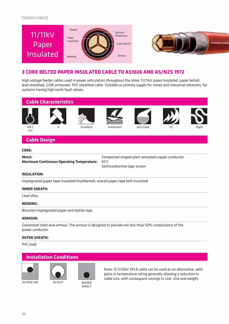
3 CORE BELTED PAPER INSULATED CABLE TO AS1026 AND AS/NZS 1972
High voltage feeder cables used in power reticulation throughout the mine. 11/11kV paper insulated, paper belted,
lead sheathed, GSW armoured, PVC sheathed cable. Suitable as primary supply for mines and industrial networks, for
systems having high earth fault values.
Note: 12.7/22kV XPLE cable can be used as an alternative, with
gains in temperature rating generally allowing a reduction in
cable size, with consequent savings in cost, size and weight.
Cable Characteristics
Installation Conditions
Cable Design
CORE:
Metal: Compacted shaped plain annealed copper conductor
Maximum Continuous Operating Temperature: 65˚C
Semiconductive tape screen
INSULATION:
Impregnated paper tape insulated (numbered), overall paper tape belt insulated
INNER SHEATH:
Lead alloy
BEDDING:
Bitumen impregnated paper and textile tape
ARMOUR:
Galvanised steel wire armour. The armour is designed to provide not less than 50% conductance of the
power conductor
OUTER SHEATH:
PVC (red)
+65˚C
-0˚C
IN FREE AIR IN DUCT
4 Excellent Immersion Very Good C3 Rigid
Armour
Sheath
Paper
Insulation
Sectoral
Phase Core
Lead Sheath
Bedding
BURIED
DIRECT
31
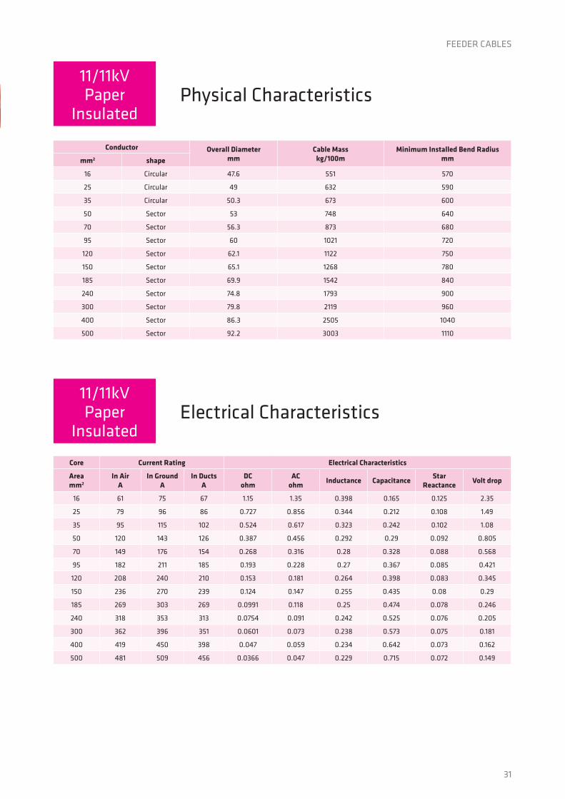
Physical Characteristics
Electrical Characteristics
Conductor Overall Diametermm
Cable Masskg/100m
Minimum Installed Bend Radiusmmmm2 shape
16 Circular 47.6 551 570
25 Circular 49 632 590
35 Circular 50.3 673 600
50 Sector 53 748 640
70 Sector 56.3 873 680
95 Sector 60 1021 720
120 Sector 62.1 1122 750
150 Sector 65.1 1268 780
185 Sector 69.9 1542 840
240 Sector 74.8 1793 900
300 Sector 79.8 2119 960
400 Sector 86.3 2505 1040
500 Sector 92.2 3003 1110
Core Current Rating Electrical Characteristics
Areamm2
In AirA
In GroundA
In DuctsA
DCohm
ACohm
Inductance CapacitanceStar
ReactanceVolt drop
16 61 75 67 1.15 1.35 0.398 0.165 0.125 2.35
25 79 96 86 0.727 0.856 0.344 0.212 0.108 1.49
35 95 115 102 0.524 0.617 0.323 0.242 0.102 1.08
50 120 143 126 0.387 0.456 0.292 0.29 0.092 0.805
70 149 176 154 0.268 0.316 0.28 0.328 0.088 0.568
95 182 211 185 0.193 0.228 0.27 0.367 0.085 0.421
120 208 240 210 0.153 0.181 0.264 0.398 0.083 0.345
150 236 270 239 0.124 0.147 0.255 0.435 0.08 0.29
185 269 303 269 0.0991 0.118 0.25 0.474 0.078 0.246
240 318 353 313 0.0754 0.091 0.242 0.525 0.076 0.205
300 362 396 351 0.0601 0.073 0.238 0.573 0.075 0.181
400 419 450 398 0.047 0.059 0.234 0.642 0.073 0.162
500 481 509 456 0.0366 0.047 0.229 0.715 0.072 0.149
11/11kVPaper
Insulated
11/11kVPaper
Insulated
FEEDER CABLES

32
6.35/11kV
Copper
3 CORE COPPER WIRE SCREENED ARMOURED TO AS/NZS 1972
Note: The cables in this brochure are not specifically designed for use as self supporting cables, as submarine
cables or where exposure to excessive heat and/or corrosive products is involved. In case of any doubt concerning
the suitability of a particular cable type for a particular application, guidance should be sought from the Prysmian
Customer Service Team.
Cable Characteristics
Installation Conditions
Cable Design
CORE:
Metal: Plain circular compacted copper
Maximum Continuous Operating Temperature: 90˚C
CONDUCTOR SCREEN:
Extruded semi-conducting compound, bonded to the insulation and applied in the same operation as the insulation
INSULATION:
Cross Linked Polyethylene (XLPE) - standard
INSULATION SCREEN:
Extruded semi-conducting compound
METALLIC SCREEN:
Plain annealed copper wire. Combined screen area is designed to provide not less than 50% conductance of one
associated power conductor
ARMOUR:
Galvanised steel wires
OUTER SHEATH:
Red 5V-90 polyvinyl chloride (PVC)
+90˚C
-25˚C
12D
IN FREE AIR IN DUCT
4 Very Good Splashes Very Good C2 Rigid
Conductor
Screen
Metallic
Screen
SheathArmour
Phase Core
IN GROUND 18D IN TRENCH
FEEDER CABLES

33
Product Code 25XFED3C11 35XFED3C11 50XFED3C11 70XFED3C11 95XFED3C11 120XFED3C11 150XFED3C11 185XFED3C11 240XFED3C11
Nominal Conductor Area mm2
25 35 50 70 95 120 150 185 240
Nominal Con-ductor Diameter mm
6.1 7.0 8.2 9.8 11.5 12.9 14.3 16.0 18.2
NominalWire Armour Diameter mm
2.5 2.5 2.5 2.5 2.5 2.5 2.5 3.15 3.15
NominalDiameter mm
51.3 53.5 56.3 60.4 64.4 67.9 71.3 79.5 85.1
Nominal Mass kg/100m
425 475 539 646 778 888 101 129 153
Pulling Tension: Cond(s) kN
5.3 7.4 10.5 14.7 20.0 25.0 25.0 25.0 25.0
Pulling Tension: Stocking kN
5.3 7.4 10.5 12.4 14.2 15.8 17.4 22 25
Pulling Tension: Armour Wires kN
10.4 11.4 12.6 14.6 16.8 18.5 20.6 25.0 25.0
Min Bending Radius During Install mm
920 960 1010 1090 1160 1220 1280 1430 1530
Min Bending Radius Set In Position mm
620 640 680 720 770 810 860 950 1020
Rdc @ Ref Temp: Phase Cond Ohm/km
0.727 0.524 0.387 0.268 0.193 0.153 0.124 0.0991 0.0754
Rac @ Oper Temp: Phase Conductor
0.927 0.668 0.494 0.342 0.247 0.196 0.159 0.128 0.0983
Inductance mH/km
0.415 0.397 0.379 0.349 0.333 0.319 0.310 0.309 0.298
Inductance Reactance Ohm/km
0.130 0.124 0.119 0.109 0.104 0.100 0.097 0.097 0.0914
Zo @ Ref temp: Ro Ohm/km
4.00+j0.078 3.51+j0.018 2.51+j0.073 1.76+j0.063 1.29+j0.059 1.02+j0.054 0.82+j0.051 0.66+j0.050 0.52+j0.047
Capacitance: Phase To Earth uF/km
0.211 0.230 0.254 0.289 0.324 0.353 0.382 0.418 0.463
Capacitance: Charging curr. per phase A/km
0.42 0.46 0.51 0.58 0.65 0.70 0.76 0.83 0.92
ISC: Phase Cond. kA, 1 sec
3.6 5.0 7.2 10.0 13.6 17.2 21.5 26.5 34.3
In ground, direct buried A
140 165 195 235 290 330 370 410 475
In ground, in duct A
120 145 170 205 245 280 310 350 410
In free air A 135 160 190 235 295 345 385 440 520
FEEDER CABLES
Characteristics6.35/11kV
Copper

34
12.7/22kV
Copper
FEEDER CABLES
3 CORE COPPER WIRE SCREENED ARMOURED TO AS/NZS 1972
Note: The cables in this brochure are not specifically designed for use as self supporting cables, as submarine
cables or where exposure to excessive heat and/or corrosive products is involved. In case of any doubt concerning
the suitability of a particular cable type for a particular application, guidance should be sought from the Prysmian
Customer Service Team.
Cable Characteristics
Installation Conditions
Cable Design
CORE:
Metal: Plain circular compacted copper
Maximum Continuous Operating Temperature: 90˚C
CONDUCTOR SCREEN:
Extruded semi-conducting compound, bonded to the insulation and applied in the same operation as the insulation
INSULATION:
Cross Linked Polyethylene (XLPE) - standard
INSULATION SCREEN:
Extruded semi-conducting compound
METALLIC SCREEN:
Plain annealed copper wire. Combined screen area is designed to provide not less than 50% conductance of one
associated power conductor
ARMOUR:
Galvanised steel wires
OUTER SHEATH:
Red 5V-90 polyvinyl chloride (PVC)
+90˚C
-25˚C
12D
IN FREE AIR IN DUCT
4 Very Good Splashes Very Good C2 Rigid
IN GROUND 18D
Conductor
Screen
Metallic
Screen
SheathArmour
Phase Core
IN TRENCH
35
FEEDER CABLES
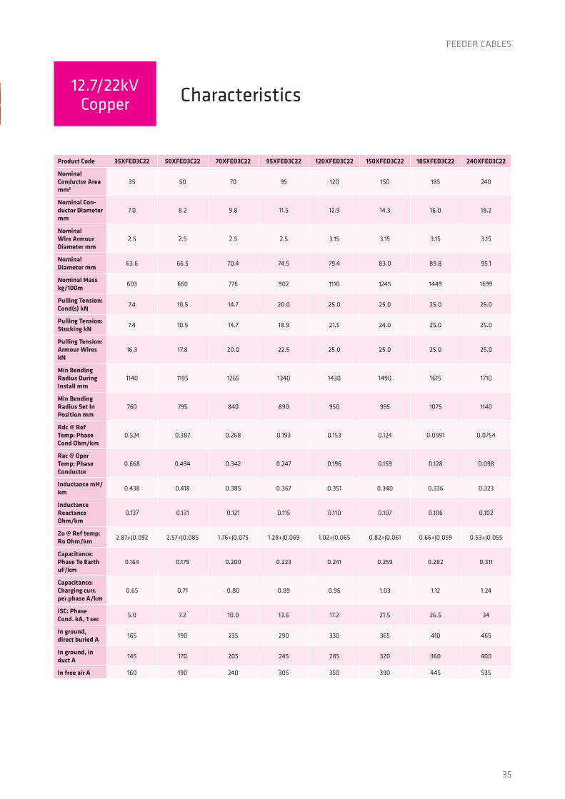
Product Code 35XFED3C22 50XFED3C22 70XFED3C22 95XFED3C22 120XFED3C22 150XFED3C22 185XFED3C22 240XFED3C22
Nominal Conductor Area mm2
35 50 70 95 120 150 185 240
Nominal Con-ductor Diameter mm
7.0 8.2 9.8 11.5 12.9 14.3 16.0 18.2
NominalWire Armour Diameter mm
2.5 2.5 2.5 2.5 3.15 3.15 3.15 3.15
NominalDiameter mm
63.6 66.5 70.4 74.5 79.4 83.0 89.8 95.1
Nominal Mass kg/100m
603 660 776 902 1110 1245 1449 1699
Pulling Tension: Cond(s) kN
7.4 10.5 14.7 20.0 25.0 25.0 25.0 25.0
Pulling Tension: Stocking kN
7.4 10.5 14.7 18.9 21.5 24.0 25.0 25.0
Pulling Tension: Armour Wires kN
16.3 17.8 20.0 22.5 25.0 25.0 25.0 25.0
Min Bending Radius During Install mm
1140 1195 1265 1340 1430 1490 1615 1710
Min Bending Radius Set In Position mm
760 795 840 890 950 995 1075 1140
Rdc @ Ref Temp: Phase Cond Ohm/km
0.524 0.387 0.268 0.193 0.153 0.124 0.0991 0.0754
Rac @ Oper Temp: Phase Conductor
0.668 0.494 0.342 0.247 0.196 0.159 0.128 0.098
Inductance mH/km
0.438 0.418 0.385 0.367 0.351 0.340 0.336 0.323
Inductance Reactance Ohm/km
0.137 0.131 0.121 0.115 0.110 0.107 0.106 0.102
Zo @ Ref temp: Ro Ohm/km
2.87+j0.092 2.57+j0.085 1.76+j0.075 1.28+j0.069 1.02+j0.065 0.82+j0.061 0.66+j0.059 0.53+j0.055
Capacitance: Phase To Earth uF/km
0.164 0.179 0.200 0.223 0.241 0.259 0.282 0.311
Capacitance: Charging curr. per phase A/km
0.65 0.71 0.80 0.89 0.96 1.03 1.12 1.24
ISC: Phase Cond. kA, 1 sec
5.0 7.2 10.0 13.6 17.2 21.5 26.5 34
In ground, direct buried A
165 190 235 290 330 365 410 465
In ground, in duct A
145 170 205 245 285 320 360 400
In free air A 160 190 240 305 350 390 445 535
Characteristics12.7/22kV
Copper

Greg NewmanNational Business Development Manager - Mining
Phone: +61 412 144 226
Email: [email protected]