Embed Size (px)
Citation preview

800-543-9038 USA 866-805-7089 CANADA 203-791-8396 LATIN AMERICA
147
M40
024
- 05
/10
- Su
bjec
t to
chan
ge. ©
Bel
imo
Airc
ontro
ls (U
SA),
Inc.
Electronic Fail-Safe Series Direct Coupled Actuators
Minimum 360 in-lb torque - GK• For damper areas up to 90 sq. ft*
Minimum 54 in-lb torque - NKQ• For damper areas up to 12 sq. ft*
Minimum 101 lbf - AHQ
AAll Actuators have BDCM
Basic Product ● ● ● ● ● ●
Flexible Product ● ● ● ● ● ● ● ●
Torque 360 in-lb 360 in-lb 360 in-lb 360 in-lb 360 in-lb 360 in-lb 54 in-lb 54 in-lb 54 in-lb 101 lbfAngle of Rotation 95 degrees ● ● ● ● ● ● ● ● ●
Power Supply 24 VAC/DC ● ● ● ● ● ● ● ● ● ●
Control Input On/Off ●
On/Off, Floating Point ● ●
2 to 10 VDC (4 to 20mA) ● ● ●
Multi-Function Technology ● ● ● ●
Feedback None ● ● ●
2 to 10 VDC ● ● ●
Variable (2 to 10 VDC) ● ● ● ●
Running Time Seconds 150 150 150 150 150 default
150 default 4 4 4 default 150
Adj. (90-150) (90-150) (4-16)Wiring Plenum Rated Cable ● ● ● ● ● ● ●
Conduit Fitting ● ● ● ● ● ● ● ● ● ●
Auxiliary Switch Add-On ● ● ● ● ● ● ● ● ●
*Based on 4 in-lb/ft2 damper torque loading. Parallel blade. No edge seals.
Electronic Fail-Safe Series At A Glance
GKB2
4-3,
GKX
24-3
(p. 1
49)
GKB2
4-SR
, GKX
24-S
R (p
. 153
)
GKX2
4-M
FT (p
. 157
)
NKQB
24-S
R, N
KQX2
4-SR
(p. 1
63)
NKQ
X24-
MFT
(p. 1
65)
AHKX
24-M
FT-1
00 (p
. 167
)
NKQB
24-1
, NKQ
X24-
1 (p
. 161
)
GKB2
4-3-
T N4
(p. 1
51)
GKB2
4-SR
-T N
4 (p
. 155
)
GKB2
4-M
FT-T
N4
(p. 1
59)

800-543-9038 USA 866-805-7089 CANADA 203-791-8396 LATIN AMERICA
148
M40
024
- 05
/10
- Su
bjec
t to
chan
ge. ©
Bel
imo
Airc
ontro
ls (U
SA),
Inc.
Electronic Fail-Safe Series Direct Coupled Actuators
A CLOSER LOOK…• Brushless DC Motor for Added Accuracy and Controllability
• Cut Labor Costs with Simple Direct Coupling
• Self-Centers on 1.05" or 3/4" with the Standard Clamp
• Check Damper Position with Clear Position Indicator
• Don't Worry about Actuator Burn-Out; Belimo is OverloadProof throughout Rotation
• Enjoy Added Flexibility with Easy Mechanical Stops to Adjust Angle of Rotation
• Need to Change Control Direction?Do it easily with a Simple Switch
• Easily Accessible Manual Override Button helps you Pre-Tension Damper Blades
• Auxiliary Switch and Feedback Potentiometer Add-Ons MountDirectly on Clamp, Includes Conduit Connector
• Added Flexibility to Select Clamp, Electrical Connection,and Running Time to fi t your Specifi c Application withBelimo's New Flexible Line of Actuators
• Preset the Fail Position in 10% increments
• Patented loading of the caps for longer life
• Programmable delay for brown outs and quick power dips
• Front Panel LED to notify if there are issues with the caps
• Standard 3ft Plenum Rated Cable and Conduit ConnectorProvided on Basic Models
The Belimo Difference• Customer Commitment
Extensive product range. Application assistance. Same-day shipments. Free technical support. Five year warranty.
• Low Installation and Life-Cycle CostEasy installation. Accuracy and repeatability.
Low power consumption. No maintenance.
• Long Service LifeComponents tested before assembly. Every product tested before shipment.
30+ years direct coupled actuator design.

800-543-9038 USA 866-805-7089 CANADA 203-791-8396 LATIN AMERICA
149
M40
024
- 05
/10
- Su
bjec
t to
chan
ge. ©
Bel
imo
Airc
ontro
ls (U
SA),
Inc.
GKB24-3, GKX24-3On/Off, Floating Point, Fail-Safe, Operation, Direct Coupled, 24V
Technical Data GKB24-3, GKX24-3Power supply 24VAC ±20% 50/60Hz
24VDC ±10%Power consumption 12W (3W)Transformer sizing 21VA (class 2 power source)Electrical connection 18 GA plenum rated cable
½" conduit connectorprotected NEMA 2 (IP54)3 ft [1m] 10 ft [3m] 16 ft [5m]
Overload protection electronic throughout 0 to 95 rotationOperation range Y on/off, fl oating pointInput impedance 100kΩ (0.1 mA), 500Ω
1500Ω (fl oating point, on/off)Feedback output U 2 to 10VDC, 0.5mA max, VDC variableAngle of rotation max. 95°, adjustable with mechanical stop
electronically variableTorque 360 in-lb [40 Nm]Direction of rotation reversible with switch Fail-safe position adjustable with dial or tool 0 to 100% in 10%
incrementsPosition indication refl ective visual indicator (snap-on)Manual override external push buttonRunning time normal operation fail-safe
150 seconds (default), variable 90 to 150 seconds35 seconds
Humidity 5 to 95% RH non-condensing (EN 60730-1)Ambient temperature -22°F to +122°F [-30°C to +50°C]Storage temperature -40°F to +176°F [-40°C to +80°C]Housing NEMA2, IP54, UL enclosure type 2Housing material UL94-5VAAgency list cULus acc. to UL 60730-1A/-2-14
CAN/CSA E60730-1:02CE acc. to 2004/108/EEC and 2006/95/EC
Noise level < 45dB(A)Servicing maintenance freeQuality standard ISO 9001Weight 3.85 lbs [1.75 kg]
Torque min. 360 in-lb for control damper surfaces up to 90 sq ft.
ApplicationFor proportional modulation of dampers in HVAC systems.
The GKB24-3 and GKX24-3 provide electrical power off operation for reliablefail-safe application.
The actuator is mounted directly to a damper shaft up to 1.05“ in diameter by a universal clamp. A crank arm and several mounting brackets are available forapplications where actuator cannot be direct coupled to the damper shaft.
OperationThe actuator is electronically protected against overload. The anti-rotationstrap supplied with the actuator will prevent lateral movement.
The GKB24-3 and GKX24-3 actuators provide 95° of rotation and a visual indicator shows the position of the actuator. When reaching the damper oractuator end position, the actuator automatically stops. The gear can bemanually disengaged by pressing the button located on the actuator cover.
The GKB24-3 and GKX24-3 actuators use a brushless DC motor, which iscontrolled by an Application Specifi c Integrated Circuit (ASIC). The ASICmonitors and controls the actuators rotation and provides a digital rotationsensing (DRS) function to prevent damage to the actuator in a stall condition. Power consumption is reduced in a holding mode.
Add-on auxiliary switches or feedback potentiometers are easily fasteneddirectly onto the actuator body for signaling and switching functions.
Dimensions (inches [mm])
7.05” [179]
6.73” [171]1.58” [40] 1.42” [36]
2.36
” [60
]4.
57” [
116]
3.43
” [87
]
D31
3

800-543-9038 USA 866-805-7089 CANADA 203-791-8396 LATIN AMERICA
150
M40
024
- 05
/10
- Su
bjec
t to
chan
ge. ©
Bel
imo
Airc
ontro
ls (U
SA),
Inc.
GKB24-3, GKX24-3On/Off, Floating Point, Fail-Safe, Operation, Direct Coupled, 24V
AccessoriesK-GM20 ¾" [20mm] Shaft ClampZG-102 Multiple Actuator Mounting BracketZG-GMA Crank arm Adaptor KitZG-JSA (-1,2,3) Jackshaft Adaptors for Hollow JackshaftsZS-100 Weather Shield - SteelZS-150 Weather Shield - PolycarbonateZS-260 Explosion Proof HousingZS-300 (-1) (-5) NEMA 4X HousingTool-07 13 mm WrenchPS-100 Actuator Power Supply SimulatorS1A, S2A Auxiliary Switch(es)P370 Shaft Mount Auxiliary SwitchP…A Feedback PotentiometersNote: When using GKB24-3, GKX24-3 actuators, only use accessories listed on this
page.
Typical Specifi cation
On/off, fl oating point control damper actuators shall be electronic direct-coupled type, which require no crank arm and linkage and be capable of directmounting to shaft up to 1.05" diameter. Actuators shall have brushless DC motortechnology and be protected from overload at all angles of rotation. Actuatorsshall have reversing switch and manual override on the cover. Run time shallbe constant and independent of torque. Actuators shall be cULus listed, havea 5-year warranty, and be manufactured under ISO 9001 International Quality Control Standards. Actuators shall be as manufactured by Belimo.
W39
9_10
On/Off controlOff l
W39
9_10
Floating Point control
Wiring Diagrams
1 Provide overload protection and disconnect as required.
2 CAUTION Equipment Damage!NActuators may be connected in parallel if not mechanically mounted to the same shaft. Power consumption and input impedance must be observed.
3 Actuators may also be powered by 24 VDC.
4Position feedback cannot be used with Triac sink controller.The actuator internal common reference is not compatible.
5Control signal may be pulsed from either the Hot (source)or the Common (sink) 24 VAC line.
8Contact closures A & B also can be triacs.A & B should both be closed for triac source and open for triac sink.
9For triac sink the common connection from the actuatormust be connected to the hot connection of the controller.
Meets UL requirements without the need of an electrical ground connection.
WARNING Live Electrical Components!GDuring installation, testing, servicing and troubleshooting of this product, it may be necessary to work with live electrical components. Have a qualifi ed licensed electrician or other individual who has been properly trained in handling live electrical components perform these tasks. Failure to follow allelectrical safety precautions when exposed to live electrical components could result in death or serious injury.
Electrical Installation
Wiring diagram
Y U
1 32 5
– +
T ~
Cable colors:1 = black2 = red3 = white5 = orange
Cable lengths
Y U
1 32 5
T ~
A
C
L1
L2
Ltot
A = ActuatorC = Control unitL1 = Belimo connecting cable, 1 m (4 x 0.75 mm2)L2 = Customer cableLtot = Maximum cable length
Cross sectionL2T
/
~
Max. cable lengthLtot = t L1 + L2
Example for DC
AC DC0.75 mm2 <30 m <5 m 1 m (L1) + 4 m (L2)
1.00 mm2 <40 m <8 m 1 m (L1) + 7 m (L2)
1.50 mm2 <70 m <12 m 1 m (L1) + 11 m (L2)
2.50 mm2 <100 m <20 m 1 m (L1) + 19 m (L2)
LN
Y U
T
1 32 5
A
CAACA 24 VVV
ACCC 230 VV
L1
A = ActuatorC = Control unitL1 = Belimo connecting cable, 1 m (4 x 0.75 mm2mm )
Note• Connect via safety isolation transformer.• Parallel connection of other actuators possible.
Note performance data for supply.
! DC 0 ... 10 V
DC 2 ... 10 V
NoteWhen several actuators are connected in parallel,the maximum cable length must be divided by thenumber of actuators.
NoteThere are no special restrictions on installation if the supply and data cable are routed separately.

800-543-9038 USA 866-805-7089 CANADA 203-791-8396 LATIN AMERICA
151
M40
024
- 05
/10
- Su
bjec
t to
chan
ge. ©
Bel
imo
Airc
ontro
ls (U
SA),
Inc.
GKB24-3-T N4NEMA 4, On/Off, Floating Point Control, Electronic Fail-Safe, Direct Coupled, 24V
Technical Data GKB24-3-T N4Power supply 24VAC ±20% 50/60Hz
24VDC ±10%Power consumption 12W (3W)Transformer sizing 21VA (class 2 power source)Electrical connection screw terminal (for 26 to 14 GA wire)
½" conduit connectorOverload protection electronic throughout 0 to 95° rotationControl on/off, fl oating pointInput impedance 100kΩAngle of rotation max. 95°, adjustable with mechanical stopTorque 360 in-lb [40 Nm]Direction of rotation reversible with switch Position indication dialRunning timeMotor fail-safe
150 seconds constant independent of load35 seconds
Humidity 5 to 100% RH (UL Type 4)Ambient temperature -22°F to +122°F [-30°C to +50°C]Storage temperature -40°F to +176°F [-40°C to +80°C]Housing UL Type 4, NEMA 4, IP66/67Housing material polycarbonateAgency listings† cULus acc. to UL 60730-1A/-2-14
CAN/CSA E60730-1, CSA C22.2 No. 24-93,CE acc. to 89/336/EEC
Noise level <45dB(A)Servicing maintenance freeQuality standard ISO 9001Weight 10.4 lbs [4.71 kg]
Torque min. 360 in-lb for control of damper surfaces up to 90 sq ft.
ApplicationFor on/off and fl oating point control of dampers in HVAC systems. Actuator sizing should be done in accordance with the damper manufacturer'sspecifi cations
The actuator is mounted directly to a damper shaft up to 1.05" in diameter by auniversal clamp, self-centered default.
OperationThe actuator is electronically protected against overload. The anti-rotationstrap supplied with the actuator will prevent lateral movement.
The GKB24-3-T N4 provides 95° of rotation and a visual indicator shows the position of the actuator. When reaching the damper or actuator end position, the actuator automatically stops. The gears can be manually disengaged bypressing the button located on the actuator cover.
The GKB24-3-T N4 actuator uses a sensorless brushless DC motor, which is controlled by an Application Specifi c Integrated Circuit (ASIC). The ASICmonitors and controls the actuator's rotation and provides a digital rotation sensing (DRS) function to prevent damage to the actuator in a stall condition. Power consumption is reduced in a holding mode.
Add-on auxiliary switches or feedback potentiometers are easily fasteneddirectly onto the actuator body for signaling and switching functions.
Dimensions (inches [mm])
172
[6.7
7]
D31
2
800-543-9038 USA 866-805-7089 CANADA 203-791-8396 LATIN AMERICA
152
M40
024
- 05
/10
- Su
bjec
t to
chan
ge. ©
Bel
imo
Airc
ontro
ls (U
SA),
Inc.
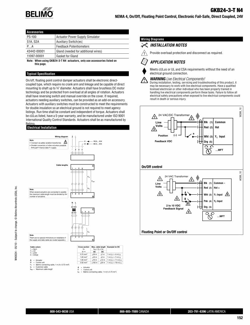
GKB24-3-T N4NEMA 4, On/Off, Floating Point Control, Electronic Fail-Safe, Direct Coupled, 24V
AccessoriesPS-100 Actuator Power Supply SimulatorS1A, S2A Auxiliary Switch(es)P…A Feedback Potentiometers43442-00001 Gland (needed for additional wires)11097-00001 Gasket for GlandNote: When using GKB24-3-T N4 actuators, only use accessories listed on
this page.
Typical Specifi cation
On/off, fl oating point control damper actuators shall be electronic direct-coupled type, which require no crank arm and linkage and be capable of directmounting to shaft up to ¾" diameter. Actuators shall have brushless DC motor technology and be protected from overload at all angles of rotation. Actuatorsshall have reversing switch and manual override on the cover. If required,actuators needing auxiliary switches, can be provided as an add-on accessory. Actuators with auxiliary switches must be constructed to meet the requirementsfor double insulation so an electrical ground is not required to meet agencylistings. Run time shall be constant and independent of torque. Actuators shallbe cULus listed, have a 5-year warranty, and be manufactured under ISO 9001International Quality Control Standards. Actuators shall be as manufactured byBelimo.
Wiring Diagrams
1 Provide overload protection and disconnect as required.
Meets cULus or UL and CSA requirements without the need of anelectrical ground connection.
WARNING Live Electrical Components!GDuring installation, testing, servicing and troubleshooting of this product, it may be necessary to work with live electrical components. Have a qualifi ed licensed electrician or other individual who has been properly trained in handling live electrical components perform these tasks. Failure to follow allelectrical safety precautions when exposed to live electrical components could result in death or serious injury.
W39
9_10
On/Off control
W39
9_10
Floating Point or On/Off control
Electrical Installation
Wiring diagram
YU
1 32 5
– +
T ~
Cable colors:1 = black2 = red3 = white5 = orange
Cable lengths
Y U
1 32 5
T ~
A
C
L1
L2
Ltot
A = ActuatorC = Control unitL1 = Belimo connecting cable, 1 m (4 x 0.75 mm2)L2 = Customer cableLtot = Maximum cable length
Cross sectionL2T
/
~
Max. cable lengthLtot =t L1 + L2
Example for DC
AC DC0.75 mm2 <30 m <5 m 1 m (L1) + 4 m (L2)
1.00 mm2 <40 m <8 m 1 m (L1) + 7 m (L2)
1.50 mm2 <70 m <12 m 1 m (L1) + 11 m (L2)
2.50 mm2 <100 m <20 m 1 m (L1) + 19 m (L2)
LN
Y U
T
1 32 5
A
CAACA 24 VVV
ACCC 230 VV
L1
A = ActuatorC = Control unitL1 = Belimo connecting cable, 1 m (4 x 0.75 mm2mm )
Note• Connect via safety isolation transformer.• Parallel connection of other actuators possible.
Note performance data for supply.
! DC 0 ... 10 V
DC 2 ... 10 V
NoteWhen several actuators are connected in parallel,the maximum cable length must be divided by thenumber of actuators.
NoteThere are no special restrictions on installation if the supply and data cable are routed separately.

800-543-9038 USA 866-805-7089 CANADA 203-791-8396 LATIN AMERICA
153
M40
024
- 05
/10
- Su
bjec
t to
chan
ge. ©
Bel
imo
Airc
ontro
ls (U
SA),
Inc.
GKB24-SR, GKX24-SRProportional Control, Fail-Safe, Operation, Direct Coupled, 24V, for 2 to 10 VDC and 4 to 20mA
Technical Data GKB24-SR, GKX24-SRPower supply 24VAC ±20% 50/60Hz
24VDC ±10%Power consumption 12W (3W)Transformer sizing 21VA (class 2 power source)Electrical connection 18 GA plenum rated cable
½" conduit connectorprotected NEMA 2 (IP54)3 ft [1m] 10 ft [3m] 16 ft [5m]
Overload protection electronic throughout 0 to 95 rotationOperation range Y 2 to 10 VDC, 4 to 20mA (default)Input impedance 100kΩ (0.1 mA), 500ΩFeedback output U 2 to 10VDC, 0.5mA max, VDC variableAngle of rotation max. 95°, adjustable with mechanical stop
electronically variableTorque 360 in-lb [40 Nm]Direction of rotation reversible with switch Fail-safe position adjustable with dial or tool 0 to 100% in 10%
incrementsPosition indication refl ective visual indicator (snap-on)Manual override external push buttonRunning time normal operation fail-safe
150 seconds (default), variable 90 to 150 seconds35 seconds
Humidity 5 to 95% RH non-condensing (EN 60730-1)Ambient temperature -22°F to +122°F [-30°C to +50°C]Storage temperature -40°F to +176°F [-40°C to +80°C]Housing NEMA2, IP54, UL enclosure type 2Housing material UL94-5VAAgency list cULus acc. to UL 60730-1A/-2-14
CAN/CSA E60730-1:02CE acc. to 2004/108/EEC and 2006/95/EC
Noise level < 45dB(A)Servicing maintenance freeQuality standard ISO 9001Weight 3.85 lbs [1.75 kg]
Torque min. 360 in-lb for control damper surfaces up to 90 sq ft.
ApplicationFor proportional modulation of dampers in HVAC systems.
The GKB24-SR and GKX24-SR provide electrical power off operation forreliable fail-safe application.
The actuator is mounted directly to a damper shaft up to 1.05" in diameter by auniversal clamp. A crank arm and several mounting brackets are available forapplications where actuator cannot be direct coupled to the damper shaft.
The actuator operates in response to a 2 to 10 VDC, or with the addition of a 500 Ω resistor, a 4 to 20mA control input from an electronic controller orpositioner. A 2 to 10 VDC feedback signal is provided for position indication or master-slave applications.
OperationThe actuator is electronically protected against overload. The anti-rotationstrap supplied with the actuator will prevent lateral movement.
The GKB24-SR and GKX24-SR provide 95° of rotation and a visual indicatorshows the position of the actuator. When reaching the damper or actuatorend position the actuator automatically stops. The gear can be manually disengaged by pressing the button located on the actuator cover.
The GKB24-SR and GKX24-SR actuators use a brushless DC motor, which is controlled by an Application Specifi c Integrated Circuit (ASIC). The ASICmonitors and controls the actuators rotation and provides a digital rotationsensing (DRS) function to prevent damage to the actuator in a stall condition. Power consumption is reduced in a holding mode.
Add-on auxiliary switches or feedback potentiometers are easily fasteneddirectly onto the actuator body for signaling and switching functions.
Dimensions (inches [mm])
7.05” [179]
6.73” [171]1.58” [40] 1.42” [36]
2.36
” [60
]4.
57” [
116]
3.43
” [87
]
D31
3

800-543-9038 USA 866-805-7089 CANADA 203-791-8396 LATIN AMERICA
154
M40
024
- 05
/10
- Su
bjec
t to
chan
ge. ©
Bel
imo
Airc
ontro
ls (U
SA),
Inc.
GKB24-SR, GKX24-SRProportional Control, Fail-Safe, Operation, Direct Coupled, 24V, for 2 to 10 VDC and 4 to 20mA
AccessoriesK-GM20 ¾" [20mm] Shaft ClampZG-102 Multiple Actuator Mounting BracketZG-GMA Crank arm Adaptor KitZG-JSA (-1,2,3) Jackshaft Adaptors for Hollow JackshaftsZS-100 Weather Shield - SteelZS-150 Weather Shield - PolycarbonateZS-260 Explosion Proof HousingZS-300 (-1) (-5) NEMA 4X HousingTool-07 13 mm WrenchPS-100 Actuator Power Supply SimulatorS1A, S2A Auxiliary Switch(es)P370 Shaft Mount Auxiliary SwitchP…A Feedback PotentiometersNote: When using GKB24-SR and GKX24-SR actuators, only use accessories listed
on this page.
Typical Specifi cation
Proportional control damper actuators shall be electronic direct-coupled type,which require no crank arm and linkage and be capable of direct mounting toshaft up to 1.05" diameter. Actuators must provide proportional damper controlresponse to a 2 to 10 VDC or, with the addition of a 500Ω resistor, a 4 to 20 mAcontrol input from an electronic controller or positioner. Actuators shall have brushless DC motor technology and be protected from overload at all angles of rotation. Actuators shall have reversing switch and manual override on thecover. Run time shall be constant and independent of torque. Actuators shall be cULus listed, have a 5-year warranty, and be manufactured under ISO 9001International Quality Control Standards. Actuators shall be as manufactured byBelimo.
W39
9_08
VDC/4-20 mA
Wiring Diagrams
1 Provide overload protection and disconnect as required.
2 CAUTION Equipment Damage!NActuators may be connected in parallel if not mechanically mounted to the same shaft. Power consumption and input impedance must be observed.
3 Actuators may also be powered by 24 VDC.
Meets UL requirements without the need of an electrical ground connection.
The ZG-R01 500 Ω resistor may be used.
WARNING Live Electrical Components!GDuring installation, testing, servicing and troubleshooting of this product, it may be necessary to work with live electrical components. Have a qualifi ed licensed electrician or other individual who has been properly trained in handling live electrical components perform these tasks. Failure to follow allelectrical safety precautions when exposed to live electrical components could result in death or serious injury.
Electrical Installation
Wiring diagram
Y U
1 32 5
– +
T ~
Cable colors:1 = black2 = red3 = white5 = orange
Cable lengths
Y U
1 32 5
T ~
A
C
L1
L2
Ltot
A = ActuatorC = Control unitL1 = Belimo connecting cable, 1 m (4 x 0.75 mm2)L2 = Customer cableLtot = Maximum cable length
Cross sectionL2T
/
~
Max. cable lengthLtot = t L1 + L2
Example for DC
AC DC0.75 mm2 <30 m <5 m 1 m (L1) + 4 m (L2)
1.00 mm2 <40 m <8 m 1 m (L1) + 7 m (L2)
1.50 mm2 <70 m <12 m 1 m (L1) + 11 m (L2)
2.50 mm2 <100 m <20 m 1 m (L1) + 19 m (L2)
LN
Y U
T
1 32 5
A
CAACA 24 VVV
ACCC 230 VV
L1
A = ActuatorC = Control unitL1 = Belimo connecting cable, 1 m (4 x 0.75 mm2mm )
Note• Connect via safety isolation transformer.• Parallel connection of other actuators possible.
Note performance data for supply.
! DC 0 ... 10 V
DC 2 ... 10 V
NoteWhen several actuators are connected in parallel,the maximum cable length must be divided by thenumber of actuators.
NoteThere are no special restrictions on installation if the supply and data cable are routed separately.

800-543-9038 USA 866-805-7089 CANADA 203-791-8396 LATIN AMERICA
155
M40
024
- 05
/10
- Su
bjec
t to
chan
ge. ©
Bel
imo
Airc
ontro
ls (U
SA),
Inc.
GKB24-SR-T N4NEMA 4, Proportional Control, Electric Fail-Safe, Direct Coupled, 24V, for 2 to 10 VDC and 4 to 20 mA
Technical Data GKB24-SR-T N4Power supply 24 VAC ± 20% 50/60 Hz
24 VDC ± 10%Power consumption 12 W (3 W)Transformer sizing 21 VA (Class 2 power source)Electrical connection screw terminal (for 26 to 14 GA wire)
½” conduit connectorOverload protection electronic throughout 0 to 95° rotationOperating range Y 2 to 10 VDC, 4 to 20 mAInput impedance 100 kΩFeedback output U 2 to 10 VDC (max 0.5 mA)Angle of rotation max. 95°, adjustable with mechanical stopTorque 360 in-lb [40 Nm]Direction of rotation reversible with switchPosition indication dialRunning timeMotor fail-safe
150 seconds, constant independent of load35 seconds
Humidity 5 to 100% RH (UL Type 4)Ambient temperature -22°F to 122°F [-30°C to 50°C]Storage temperature -40°F to 176°F [-40°C to 80°C]Housing UL Type 4, NEMA 4, IP66Housing material polycarbonateAgency listings† cULus acc. to UL 60730-1A/-2-14,
CAN/CSA E60730-1, CSA C22.2 No. 24-93,CE acc. to 89/336/EEC
Noise level <45dB(A)Servicing maintenance freeQuality standard ISO 9001Weight 10.4 lbs [4.71 kg]† Rated Impulse Voltage 800V, Type of action 1, Control Pollution Degree 3.
Torque min. 360 in-lb for control of damper surfaces up to 90 sq ft.
ApplicationFor proportional modulation of dampers in HVAC systems. Actuator sizingshould be done in accordance with the damper manufacturer’s specifi cations.
The actuator is mounted directly to a damper shaft up to 1.05” in diameter by auniversal clamp.
The actuator operates in response to a 2 to 10 VDC, or with the addition of a 500 Ω resistor, a 4 to 20 mA control input from an electronic controller orpositioner. A 2 to 10 VDC feedback signal is provided for position indication or master-slave applications.
OperationThe actuator is electronically protected against overload. The anti-rotationstrap supplied with the actuator will prevent lateral movement.
The GKB24-SR-T N4 provides 95° of rotation and a visual indicator shows the position of the actuator. When reaching the damper or actuator end position, the actuator automatically stops. The gears can be manually disengaged bypressing the button located on the actuator cover.
The GKB24-SR-T N4 actuator uses a sensorless brushless DC motor, whichis controlled by an Application Specifi c Integrated Circuit (ASIC). The ASICmonitors and controls the actuator’s rotation and provides a digital rotation sensing (DRS) function to prevent damage to the actuator in a stall condition. Power consumption is reduced in holding mode.
Add-on auxiliary switches or feedback potentiometers are easily fasteneddirectly onto the actuator body for signaling and switching functions.
Dimensions (inches [mm])
172
[6.7
7]
800-543-9038 USA 866-805-7089 CANADA 203-791-8396 LATIN AMERICA
156
M40
024
- 05
/10
- Su
bjec
t to
chan
ge. ©
Bel
imo
Airc
ontro
ls (U
SA),
Inc.
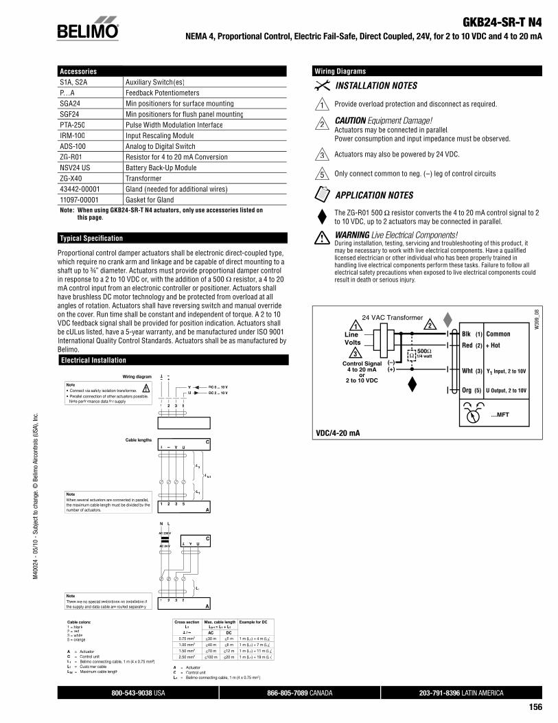
GKB24-SR-T N4NEMA 4, Proportional Control, Electric Fail-Safe, Direct Coupled, 24V, for 2 to 10 VDC and 4 to 20 mA
AccessoriesS1A, S2A Auxiliary Switch(es)P…A Feedback PotentiometersSGA24 Min positioners for surface mountingSGF24 Min positioners for fl ush panel mountingPTA-250 Pulse Width Modulation InterfaceIRM-100 Input Rescaling ModuleADS-100 Analog to Digital SwitchZG-R01 Resistor for 4 to 20 mA ConversionNSV24 US Battery Back-Up ModuleZG-X40 Transformer43442-00001 Gland (needed for additional wires)11097-00001 Gasket for GlandNote: When using GKB24-SR-T N4 actuators, only use accessories listed on
this page.
Typical Specifi cation
Proportional control damper actuators shall be electronic direct-coupled type, which require no crank arm and linkage and be capable of direct mounting to ashaft up to ¾” diameter. Actuators must provide proportional damper control in response to a 2 to 10 VDC or, with the addition of a 500 Ω resistor, a 4 to 20 mA control input from an electronic controller or positioner. Actuators shall have brushless DC motor technology and be protected from overload at allangles of rotation. Actuators shall have reversing switch and manual override on the cover. Run time shall be constant and independent of torque. A 2 to 10 VDC feedback signal shall be provided for position indication. Actuators shallbe cULus listed, have a 5-year warranty, and be manufactured under ISO 9001International Quality Control Standards. Actuators shall be as manufactured byBelimo.
Wiring Diagrams
1 Provide overload protection and disconnect as required.
2 CAUTION Equipment Damage!NActuators may be connected in parallel.Power consumption and input impedance must be observed.
3 Actuators may also be powered by 24 VDC.
5 Only connect common to neg. (–) leg of control circuits
The ZG-R01 500 Ω resistor converts the 4 to 20 mA control signal to 2to 10 VDC, up to 2 actuators may be connected in parallel.
WARNING Live Electrical Components!GDuring installation, testing, servicing and troubleshooting of this product, it may be necessary to work with live electrical components. Have a qualifi ed licensed electrician or other individual who has been properly trained in handling live electrical components perform these tasks. Failure to follow allelectrical safety precautions when exposed to live electrical components could result in death or serious injury.
W39
9_08
VDC/4-20 mA
Electrical Installation
Wiring diagram
Y U
1 32 5
– +
T ~
Cable colors:1 = black2 = red3 = white5 = orange
Cable lengths
Y U
1 32 5
T ~
A
C
L1
L2
Ltot
A = ActuatorC = Control unitL1 = Belimo connecting cable, 1 m (4 x 0.75 mm2)L2 = Customer cableLtot = Maximum cable length
Cross sectionL2T
/
~
Max. cable lengthLtot =t L1 + L2
Example for DC
AC DC0.75 mm2 <30 m <5 m 1 m (L1) + 4 m (L2)
1.00 mm2 <40 m <8 m 1 m (L1) + 7 m (L2)
1.50 mm2 <70 m <12 m 1 m (L1) + 11 m (L2)
2.50 mm2 <100 m <20 m 1 m (L1) + 19 m (L2)
LN
Y U
T
1 32 5
A
CAACA 24 VVV
ACCC 230 VV
L1
A = ActuatorC = Control unitL1 = Belimo connecting cable, 1 m (4 x 0.75 mm2mm )
Note• Connect via safety isolation transformer.• Parallel connection of other actuators possible.
Note performance data for supply.
! DC 0 ... 10 V
DC 2 ... 10 V
NoteWhen several actuators are connected in parallel,the maximum cable length must be divided by thenumber of actuators.
NoteThere are no special restrictions on installation if the supply and data cable are routed separately.

800-543-9038 USA 866-805-7089 CANADA 203-791-8396 LATIN AMERICA
157
M40
024
- 05
/10
- Su
bjec
t to
chan
ge. ©
Bel
imo
Airc
ontro
ls (U
SA),
Inc.
GKX24-MFTProportional Control, Fail-Safe, Operation, Direct Coupled, 24V, Multi-Function Technology®
Technical Data GKBX24-MFTPower supply 24VAC ±20% 50/60Hz
24VDC ±10%Power consumption 12W (3W)Transformer sizing 21VA (class 2 power source)Electrical connection 18 GA plenum rated cable
½" conduit connectorprotected NEMA 2 (IP54)3 ft [1m] 10 ft [3m] 16 ft [5m]
Overload protection electronic throughout 0 to 95 rotationOperation range Y 2 to 10 VDC, 4 to 20mA (default)
variable (VDC,PWM, fl oating point, on/off)Input impedance 100kΩ (0.1 mA), 500Ω
1500Ω (PWM, fl oating point, on/off)Feedback output U 2 to 10VDC, 0.5mA max, VDC variableAngle of rotation max. 95°, adjustable with mechanical stop
electronically variableTorque 360 in-lb [40 Nm]Direction of rotation reversible with switch Fail-safe position adjustable with dial or tool 0 to 100% in 10%
incrementsPosition indication refl ective visual indicator (snap-on)Manual override external push buttonRunning time normal operation fail-safe
95 seconds (default), variable 90 to 150 seconds35 seconds
Humidity 5 to 95% RH non-condensing (EN 60730-1)Ambient temperature -22°F to +122°F [-30°C to +50°C]Storage temperature -40°F to +176°F [-40°C to +80°C]Housing NEMA2, IP54, UL enclosure type 2Housing material UL94-5VAAgency list cULus acc. to UL 60730-1A/-2-14
CAN/CSA E60730-1:02CE acc. to 2004/108/EEC and 2006/95/EC
Noise level < 45dB(A)Servicing maintenance freeQuality standard ISO 9001Weight 3.85 lbs [1.75 kg]
Torque min. 360 in-lb for control damper surfaces up to 90 sq ft.
ApplicationFor proportional modulation of dampers in HVAC systems.
The GKBX24-MFT provides electrical power off operation for reliable fail-safe application.
The actuator is mounted directly to a damper shaft up to 1.05“ in diameter by a universal clamp. A crank arm and several mounting brackets are available forapplications where actuator cannot be direct coupled to the damper shaft.
The default parameters for 2 to 10 VDC applications of the GKBX24-MFTactuator are assigned during manufacturing. If necessary, custom versionsof the actuator can be ordered. The parameters can be changed by: pre setor custom confi guration provided by Belimo or on-site using the PC-Toolsoftware.
OperationThe actuator is electronically protected against overload. The anti-rotationstrap supplied with the actuator will prevent lateral movement.
The GKBX24-MFT provides 95° of rotation and a visual indicator shows the position of the actuator. When reaching the damper or actuator end position the actuator automatically stops. The gear can be manually disengaged by pressing the button located on the actuator cover.
The GKBX24-MFT actuator uses a brushless DC motor, which is controlledby an Application Specifi c Integrated Circuit (ASIC). The ASIC monitorsand controls the actuators rotation and provides a digital rotation sensing (DRS) function to prevent damage to the actuator in a stall condition. Power consumption is reduced in a holding mode.
Add-on auxiliary switches or feedback potentiometers are easily fasteneddirectly onto the actuator body for signaling and switching functions.
Dimensions (inches [mm])
7.05” [179]
6.73” [171]1.58” [40] 1.42” [36]
2.36
” [60
]4.
57” [
116]
3.43
” [87
]
D31
3
When combining signal and power cable together, see importantelectrical installation diagram on page 156.

800-543-9038 USA 866-805-7089 CANADA 203-791-8396 LATIN AMERICA
158
M40
024
- 05
/10
- Su
bjec
t to
chan
ge. ©
Bel
imo
Airc
ontro
ls (U
SA),
Inc.
GKX24-MFTProportional Control, Fail-Safe, Operation, Direct Coupled, 24V, Multi-Function Technology®
AccessoriesK-GM20 ¾" [20mm] Shaft ClampZG-102 Multiple Actuator Mounting BracketZG-GMA Crank arm Adaptor KitZG-JSA (-1,2,3) Jackshaft Adaptors for Hollow JackshaftsZS-100 Weather Shield - SteelZS-150 Weather Shield - PolycarbonateZS-260 Explosion Proof HousingZS-300 (-1) (-5) NEMA 4X HousingTool-07 13 mm WrenchPS-100 Actuator Power Supply SimulatorS1A, S2A Auxiliary Switch(es)P370 Shaft Mount Auxiliary SwitchP…A Feedback PotentiometersSGA24 Min positioners in NEMA 4 HousingSGF24 Min positioners for fl ush panel mountingADS-100 Analog to Digital SwitchZG-R01 Resistor for 4 to 20 mA ConversionNSV24 US Battery Back-Up ModuleZG-X40 TransformerNote: When using GKBX24-MFT actuators, only use accessories listed on this page.
Typical Specifi cation
Proportional control damper actuators shall be electronic direct-coupled type,which require no crank arm and linkage and be capable of direct mounting toshaft up to 1.05" diameter. Actuators must provide proportional damper controlresponse to a 2 to 10 VDC or, with the addition of a 500Ω resistor, a 4 to 20 mAcontrol input from an electronic controller or positioner. Actuators shall have Brushless DC motor technology and be protected from overload at all angles of rotation. Actuators shall have reversing switch and manual override on thecover. Run time shall be constant and independent of torque. Actuators shall be cULus listed, have a 5-year warranty, and be manufactured under ISO 9001International Quality Control Standards. Actuators shall be as manufactured byBelimo.
Wiring Diagrams
1 Provide overload protection and disconnect as required.
2 CAUTION Equipment Damage!NActuators may be connected in parallel if not mechanically mounted to the same shaft. Power consumption and input impedance must beobserved.
3 Actuators may also be powered by 24 VDC.
4Position feedback cannot be used with Triac sink controller.The actuator internal common reference is not compatible.
5Control signal may be pulsed from either the Hot (source)or the Common (sink) 24 VAC line.
8Contact closures A & B also can be triacs.A & B should both be closed for triac source and open for triac sink.
9For triac sink the common connection from the actuatormust be connected to the hot connection of the controller.
Meets UL requirements without the need of an electrical ground connection.
The ZG-R01 500 Ω resistor may be used.
WARNING Live Electrical Components!GDuring installation, testing, servicing and troubleshooting of this product, it may be necessary to work with live electrical components. Have a qualifi ed licensed electrician or other individual who has been properly trained in handling live electrical components perform these tasks. Failure to follow allelectrical safety precautions when exposed to live electrical components could result in death or serious injury.
W39
9_08
VDC/4-20 mA
W39
9_08
PWMM
W39
9_08
On/Off controlOff l
W39
9_08
Floating Point control

800-543-9038 USA 866-805-7089 CANADA 203-791-8396 LATIN AMERICA
159
M40
024
- 05
/10
- Su
bjec
t to
chan
ge. ©
Bel
imo
Airc
ontro
ls (U
SA),
Inc.
GKX24-MFT-T N4NEMA 4, Proportional Control, Electronic Fail-Safe, Direct Coupled, 24V, Multi-Function Technology®
Technical Data GKX24-MFT-T N4Power supply 24 VAC ± 20% 50/60 Hz
24 VDC ± 10%Power consumption 12 W (3 W)Transformer sizing 21 VA (class 2 power source)Electrical connection screw terminal (for 26 to 14 GA wire)
½” conduit connectorOverload protection electronic throughout 0 to 95° rotationOperating range Y 2 to 10 VDC, 4 to 20 mA (default)
variable (VDC, fl oating point, on/off)Input impedance 100 kΩFeedback output U 2 to 10 VDC, 0.5 mA max, VDC variableAngle of rotation max. 95°, adjustable with mechanical stop
electronically variableTorque 360 in-lb [40 Nm]Direction of rotation reversible with switchPosition indication dialRunning time
Motor fail-safe
150 seconds (default)variable (90 to 350 seconds)35 seconds
Humidity 5 to 100% RH (UL Type 4)Ambient temperature -22°F to 122°F [-30°C to 50°C]Storage temperature -40°F to 176°F [-40°C to 80°C]Housing UL Type 4, NEMA 4, IP66Housing material polycarbonateAgency listings† cULus acc. to UL 60730-1A/-2-14,
CAN/CSA E60730-1, CSA C22.2 No. 24-93,CE acc. to 89/336/EEC
Noise level <45dB(A)Servicing maintenance freeQuality standard ISO 9001Weight 10.4 lbs [4.71 kg]† Rated Impulse Voltage 800V, Type of action 1, Control Pollution Degree 3.
Torque min. 360 in-lb for control of damper surfaces up to 90 sq ft.
ApplicationFor proportional modulation of dampers in HVAC systems. Actuator sizingshould be done in accordance with the damper manufacturer’s specifi cations.
The actuator is mounted directly to a damper shaft up to 1.05” in diameter by auniversal clamp.
The default parameters for 2 to 10 VDC applications of the GKX24-MFT-T N4actuator are assigned during manufacturing. If necessary, custom versionsof the actuators can be ordered. The parameters can be changed by: pre-set or custom confi gurations provided by Belimo or on-site using the PC-Toolsoftware.
OperationThe actuator is electronically protected against overload. The anti-rotationstrap supplied with the actuator will prevent lateral movement.
The GKX24-MFT-T N4 provides 95° of rotation and a visual indicator shows the position of the actuator. When reaching the damper or actuator end position, the actuator automatically stops. The gears can be manually disengaged bypressing the button located on the actuator cover.
The GKX24-MFT-T N4 actuator uses a brushless DC motor, which is controlledby an Application Specifi c Integrated Circuit (ASIC). The ASIC monitorsand controls the actuator’s rotation and provides a digital rotation sensing(DRS) function to prevent damage to the actuator in a stall condition. Power consumption is reduced in holding mode.
Add-on auxiliary switches or feedback potentiometers are easily fasteneddirectly onto the actuator body for signaling and switching functions.
Dimensions (inches [mm])
172
[6.7
7]
When combining signal and power cable together, see importantelectrical installation diagram on page 156.
800-543-9038 USA 866-805-7089 CANADA 203-791-8396 LATIN AMERICA
160
M40
024
- 05
/10
- Su
bjec
t to
chan
ge. ©
Bel
imo
Airc
ontro
ls (U
SA),
Inc.
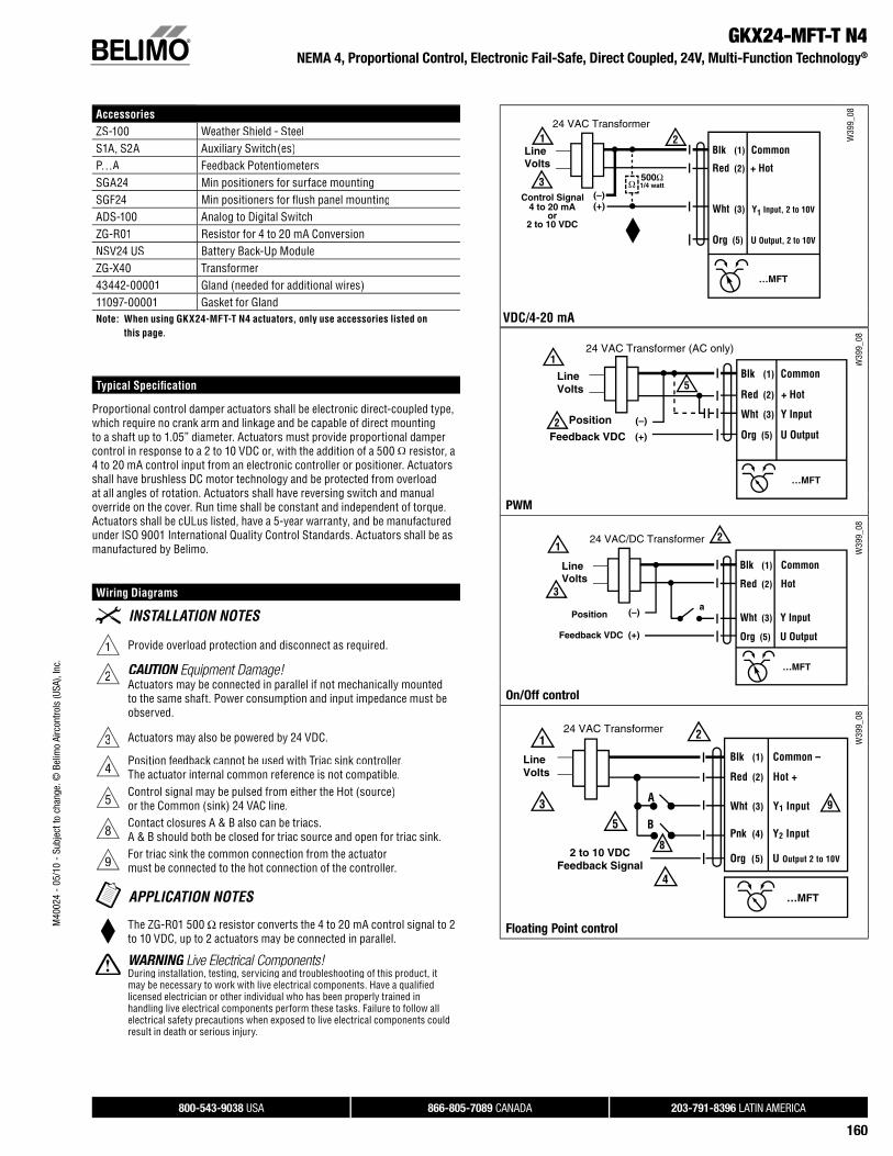
GKX24-MFT-T N4NEMA 4, Proportional Control, Electronic Fail-Safe, Direct Coupled, 24V, Multi-Function Technology®
AccessoriesZS-100 Weather Shield - SteelS1A, S2A Auxiliary Switch(es)P…A Feedback PotentiometersSGA24 Min positioners for surface mountingSGF24 Min positioners for fl ush panel mountingADS-100 Analog to Digital SwitchZG-R01 Resistor for 4 to 20 mA ConversionNSV24 US Battery Back-Up ModuleZG-X40 Transformer43442-00001 Gland (needed for additional wires)11097-00001 Gasket for GlandNote: When using GKX24-MFT-T N4 actuators, only use accessories listed on
this page.
Typical Specifi cation
Proportional control damper actuators shall be electronic direct-coupled type, which require no crank arm and linkage and be capable of direct mountingto a shaft up to 1.05” diameter. Actuators must provide proportional dampercontrol in response to a 2 to 10 VDC or, with the addition of a 500 Ω resistor, a4 to 20 mA control input from an electronic controller or positioner. Actuatorsshall have brushless DC motor technology and be protected from overload at all angles of rotation. Actuators shall have reversing switch and manual override on the cover. Run time shall be constant and independent of torque.Actuators shall be cULus listed, have a 5-year warranty, and be manufacturedunder ISO 9001 International Quality Control Standards. Actuators shall be as manufactured by Belimo.
Wiring Diagrams
1 Provide overload protection and disconnect as required.
2 CAUTION Equipment Damage!NActuators may be connected in parallel if not mechanically mounted to the same shaft. Power consumption and input impedance must beobserved.
3 Actuators may also be powered by 24 VDC.
4Position feedback cannot be used with Triac sink controller.The actuator internal common reference is not compatible.
5Control signal may be pulsed from either the Hot (source)or the Common (sink) 24 VAC line.
8Contact closures A & B also can be triacs.A & B should both be closed for triac source and open for triac sink.
9For triac sink the common connection from the actuatormust be connected to the hot connection of the controller.
The ZG-R01 500 Ω resistor converts the 4 to 20 mA control signal to 2to 10 VDC, up to 2 actuators may be connected in parallel.
WARNING Live Electrical Components!GDuring installation, testing, servicing and troubleshooting of this product, it may be necessary to work with live electrical components. Have a qualifi ed licensed electrician or other individual who has been properly trained in handling live electrical components perform these tasks. Failure to follow allelectrical safety precautions when exposed to live electrical components could result in death or serious injury.
W39
9_08
VDC/4-20 mA
W39
9_08
PWMM
W39
9_08
On/Off control
W39
9_08
Floating Point control


![).pdffrom 400-500 hp with a maximum 1850 lb-ft of peak torque. 1300 1200 1 coo TORQUE SMART TORQUE t 200 1600 Specs Horsepower [BHP @ RPM] Torque [LB-FT @ RPM] Gov. Speed [RPM] Clutch](https://img.pdfslide.us/doc/110x75/5e85d3bb659b09386c71b519/1pdf-from-400-500-hp-with-a-maximum-1850-lb-ft-of-peak-torque-1300-1200-1-coo.jpg)


![· TORQUE CURVES The Cummins ISB6.7 engine is engineered to offer ... Horsepower [BHP @ RPM] Torque [LB-FT @ RPM] Gov. Speed ... [Torque @ RPM] 300 …](https://img.pdfslide.us/doc/110x75/5b45c3047f8b9a4b558bead2/-torque-curves-the-cummins-isb67-engine-is-engineered-to-offer-horsepower.jpg)
