Embed Size (px)
Citation preview

800-543-9038 USA 866-805-7089 CANADA 203-791-8396 LATIN AMERICA
244
LHB(
X)24
-3(-
100)
(-20
0)(-
300)
(p. 2
46)
LHB(
X)24
-SR(
-100
)(-2
00) (
p. 2
48)
LHX2
4-M
FT-1
00 (p
. 250
)
LHX2
4-M
FT-2
00 (p
. 250
)
LHX2
4-M
FT-3
00 (p
. 250
)
LHQB
(X)2
4-1-
100
(p. 2
52)
LHQB
(X)2
4-M
FT-1
00 (p
. 254
)
LH Series Actuator
Minimum 34 lbf linear force For damper surfaces up to 10 sq-ft*
All Actuators have BDCM
LH Series - At A Glance
Basic ProductFlexible ProductLinear Force 34 lbf [150 N]
22 lbf [150 N]Linear Stroke 4" [100mm]
8" [200mm]12" [300mm]
Power Supply 24 VAC/DCControl Input On/Off
On/Off, Floating Point2 to 10 VDC (4 to 20mA)Multi-Function Technology
Feedback None2 to 10 VDCVariable (0 to 10 VDC)
Running Time 3.5 seconds150 secondsAdj. 75 to 150 secondsAdj. 3.5 to 15 seconds
Wiring Plenum Rated CableConduit Fitting
Installation and Operation… (page 265).
* Based on 4 in-lb/ft2 damper torque loading. Parallel blade. No edge seals.
K20
901
- 01/
09 -
Subj
ect t
o ch
ange
. © B
elim
o Ai
rcon
trols
(USA
), In
c.
800-543-9038 USA 866-805-7089 CANADA 203-791-8396 LATIN AMERICA
245
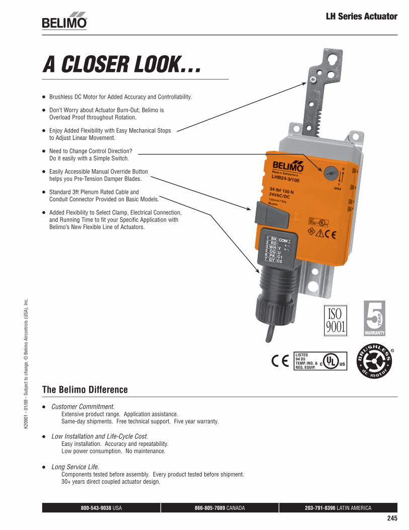
Brushless DC Motor for Added Accuracy and Controllability.
Don’t Worry about Actuator Burn-Out; Belimo is Overload Proof throughout Rotation.
Enjoy Added Flexibility with Easy Mechanical Stops to Adjust Linear Movement.
Need to Change Control Direction? Do it easily with a Simple Switch.
Easily Accessible Manual Override Button helps you Pre-Tension Damper Blades.
Standard 3ft Plenum Rated Cable and Conduit Connector Provided on Basic Models.
Added Flexibility to Select Clamp, Electrical Connection, and Running Time to fit your Specific Application with Belimo’s New Flexible Line of Actuators.
LH Series Actuator
The Belimo Difference
Customer Commitment. Extensive product range. Application assistance. Same-day shipments. Free technical support. Five year warranty.
Low Installation and Life-Cycle Cost. Easy installation. Accuracy and repeatability. Low power consumption. No maintenance.
Long Service Life. Components tested before assembly. Every product tested before shipment. 30+ years direct coupled actuator design.
A CLOSER LOOK…
K20
901
- 01/
09 -
Subj
ect t
o ch
ange
. © B
elim
o Ai
rcon
trols
(USA
), In
c.

800-543-9038 USA 866-805-7089 CANADA 203-791-8396 LATIN AMERICA
246
LHB(X)24-3(-100)(-200)(-300)On/Off, Floating Point Control, Non-Spring Return, Linear Stroke, 24V
Linear Force min. 34 lbf for control of damper surfaces up to 11 sq. ft.
ApplicationFor on/off and floating point control of dampers in HVAC systems. Actuator sizing should be done in accordance with the damper manufacturer’s specifications.
OperationThe actuator is not provided with and does not require any limit switches, but is electronically protected against overload. The anti-rotation strap supplied with the actuator will prevent lateral movement.
The LHB(X)24-3... series provides 4, 8, or 12 in of linear force. The stroke of the gear rack can be adjusted on both sides in increments of 0.8 in [20 mm] by means of the mechanical end stops.
When reaching the damper or actuator end position, the actuator automatically stops. The gears can be manually disengaged with a button on the actuator cover.
The LHB(X)24-3… actuators use a sensorless Brushless DC motor, which is controlled by an Application Specific Integrated Circuit (ASIC). The ASIC monitors and controls the actuator’s rotation and provides a digital rotation sensing (DRS) function to prevent damage to the actuator in a stall condition. Power consumption is reduced in holding mode.
Dimensions (Inches [mm])
.69"[17.4]
.54"
[13.
7]
2.64
"[6
7]
A
A
B
B
3" [75] 2" [50.8]
1.1"[27.8]
2.6"[66]
.16" [4]
0.13" [3.2]
Stroke A B4" [100] 9.2" [233.5] 8" [294.2]8" [200] 13.1" [333.5] 12" [394.2]12" [300] 17.1" [433.5] 16" [494.2]
D135
Technical Data LHB(X)24-3(-100)(-200)(-300)Power Supply 24 VAC ± 20% 50/60 Hz
24 VDC ± 20%Power Consumption 1.5 W (0.5 W)Transformer Sizing 3 VA (Class 2 power source)Electrical Connection 18 GA appliance rated cable
1/2” conduit connectorProtected NEMA 2 (IP54)
3 ft [1m] 10 ft [3m] 16 ft [5m]Overload Protection electronic throughout full strokeControl On/Off, Floating PointInput Impedance 600 Linear Stroke
LHB(X)24-3-100 4 in [100 mm]LHB(X)24-3-200 8 in [200 mm]LHX24-3-300 12 in [300 mm]
Linear Force 34 lbf [150 N]Stroke Direction reversible with switchManual Override external push buttonRunning Time 150 95 75 seconds per 4" [100mm]Humidity 5 to 95% RH non condensing (EN 60730-1)Ambient Temperature -22°F to 122°F [-30°C to 50°C]Storage Temperature -40°F to 176°F [-40°C to 80°C]Housing NEMA 2, IP54, UL enclosure type 2Housing Material UL94-5VAAgency Listings cULus acc. to UL 60730-1A/-2-14,
CAN/CSA E60730-1:02,CE acc. to 2004/108/EEC and 2006/95/EC
Noise Level (max) 35dB(A)Servicing maintenance freeQuality Standard ISO 9001Weight
LHB(X)24-3-100 0.81 lbs [365 g]LHB(X)24-3-200 0.86 lbs [390 g]LHX24-3-300 0.93 lbs [420 g]
† Rated Impulse Voltage 800V, Type of action 1.AA, Control Pollution Degree 3.
K20
901
- 01/
09 -
Subj
ect t
o ch
ange
. © B
elim
o Ai
rcon
trols
(USA
), In
c.

800-543-9038 USA 866-805-7089 CANADA 203-791-8396 LATIN AMERICA
247
LHB(X)24-3(-100)(-200)(-300) On/Off, Floating Point Control, Non-Spring Return, Linear Stroke, 24V
AccessoriesZ-DS1 Rotary Support to Compensate Lateral ForcesZ-KSC Linear CouplingP370 Shaft Mount Auxiliary SwitchNOTE: When using LHB(X)24-3… actuators, only use accessories listed on this page.
Typical Specification
Floating point, on/off control damper actuators shall be electronic type, with integrated linear stroking arm. Actuators shall have Brushless DC motor technology and be protected from overload at all positions of linear stroke. Actuators shall have reversing switch and manual override on the cover. Run time shall be constant and independent of torque. Actuators shall be cUL Approved, have a 5-year warranty, and be manufactured under ISO 9001 International Quality Control Standards. Actuators shall be as manufactured by Belimo.
Wiring Diagram
1 Provide overload protection and disconnect as required.
3 Actuators may also be powered by 24 VDC.
Meets cULus or UL and CSA Standard requirements without the need of an electrical ground connection.
WARNING Live Electrical Components! During installation, testing, servicing and troubleshooting of this product, it maybe
necessary to work with live electrical components. Have a qualified licensed electrician or other individual who has been properly trained in handling live electrical components perform these tasks. Failure to follow all electrical safety precautions when exposed to live electrical components could result in death or serious injury.
W39
3_08
On/Off control
W39
4_08
Floating Point or On/Off control
K20
901
- 01/
09 -
Subj
ect t
o ch
ange
. © B
elim
o Ai
rcon
trols
(USA
), In
c.

800-543-9038 USA 866-805-7089 CANADA 203-791-8396 LATIN AMERICA
248
LHB(X)24-SR(-100)(-200)Proportional Control, Non-Spring Return, Linear Stroke, 24V, for 2 to 10 VDC and 4 to 20 mA
Force min. 34 lbf for control of damper surfaces up to 11 sq. ft.
ApplicationFor proportional modulation of dampers in HVAC systems. Actuator sizing should be done in accordance with the damper manufacturer’s specifications.
The actuator operates in response to a 2 to 10 VDC, or with the addition of a 500 resistor, a 4 to 20 mA control input from an electronic controller or positioner. A 2 to 10 VDC feedback signal is provided for position indication or master-slave applications.
OperationThe actuator is not provided with and does not require any limit switches, but is electronically protected against overload. The anti-rotation strap supplied with the actuator will prevent lateral movement.
The LHB(X)24-SR... series provides 4 or 8 in of linear stroke. The stroke of the gear rack can be adjusted on both sides in increments of 0.8 in [20 mm] by means of the mechanical end stops.
When reaching the damper or actuator end position, the actuator automatically stops. The gears can be manually disengaged with a button on the actuator cover.
The LHB(X)24-SR… actuators use a sensorless Brushless DC motor, which is controlled by an Application Specific Integrated Circuit (ASIC). The ASIC monitors and controls the actuator’s rotation and provides a digital rotation sensing (DRS) function to prevent damage to the actuator in a stall condition. Power consumption is reduced in holding mode.
Dimensions (Inches [mm])
.69"[17.4]
.54"
[13.
7]
2.64
"[6
7]
A
A
B
B
3" [75] 2" [50.8]
1.1"[27.8]
2.6"[66]
.16" [4]
0.13" [3.2]
Stroke A B4" [100] 9.2" [233.5] 8" [294.2]8" [200] 13.1" [333.5] 12" [394.2]12" [300] 17.1" [433.5] 16" [494.2]
D135
Technical Data LHB(X)24-SR(-100)(-200)Power Supply 24 VAC ± 20% 50/60 Hz
24 VDC ± 20%Power Consumption 1.5 W (0.5 W)Transformer Sizing 3 VA (Class 2 power source)Electrical Connection 18 GA appliance rated cable
1/2” conduit connectorProtected NEMA 2 (IP54)
3 ft [1m] 10 ft [3m] 16 ft [5m]Overload Protection electronic throughout full strokeControl 2 to 10 VDC, 4 to 20 mAInput Impedance 100 k (0.1 mA), 500 Feedback Output U 2 to 10 VDC (max 0.5 mA)Linear Stroke
LHB(X)24-SR-100 4 in [100 mm]LHB(X)24-SR-200 8 in [200 mm]
Linear Force 34 lbf [150 N]Stroke Direction reversible with switch
Actuator will move in the selected direction with increasing control signal (2 to 10V)
Manual Override external push buttonRunning Time 150 95 75 seconds per 4" [100mm]Humidity 5 to 95% RH non condensing (EN 60730-1)Ambient Temperature -22°F to 122°F [-30°C to 50°C]Storage Temperature -40°F to 176°F [-40°C to 80°C]Housing NEMA 2, IP54, UL enclosure type 2Housing Material UL94-5VAAgency Listings cULus acc. to UL 60730-1A/-2-14,
CAN/CSA E60730-1:02,CE acc. to 2004/108/EEC and 2006/95/EC
Noise Level (max) 35dB(A)Servicing maintenance freeQuality Standard ISO 9001Weight
LHB(X)24-SR-100 0.81 lbs [365 g]LHB(X)24-SR-200 0.86 lbs [390 g]
† Rated Impulse Voltage 800V, Type of action 1, Control Pollution Degree 3.
K20
901
- 01/
09 -
Subj
ect t
o ch
ange
. © B
elim
o Ai
rcon
trols
(USA
), In
c.
800-543-9038 USA 866-805-7089 CANADA 203-791-8396 LATIN AMERICA
249
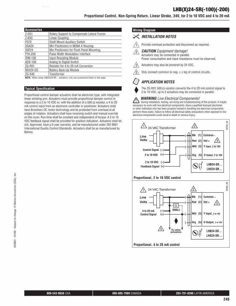
AccessoriesZ-DS1 Rotary Support to Compensate Lateral ForcesZ-KSC Linear CouplingP370 Shaft Mount Auxiliary SwitchSGA24 Min Positioners in NEMA 4 HousingSGF24 Min Positioners for Flush Panel MountingPTA-250 Pulse Width Modulation InterfaceIRM-100 Input Rescaling ModuleADS-100 Analog to Digital SwitchZG-R01 Resistor for 4 to 20 mA ConversionNSV24 US Battery Back-Up ModuleZG-X40 TransformerNOTE: When using LHB(X)24-SR… actuators, only use accessories listed on this page.
Typical Specification
Proportional control damper actuators shall be electronic type, with integrated linear stroking arm. Actuators must provide proportional damper control in response to a 2 to 10 VDC or, with the addition of a 500 resistor, a 4 to 20 mA control input from an electronic controller or positioner. Actuators shall have Brushless DC motor technology and be protected from overload at all angles of rotation. Actuators shall have reversing switch and manual override on the cover. Run time shall be constant and independent of torque. A 2 to 10 VDC feedback signal shall be provided for position indication. Actuators shall be cUL Approved, have a 5-year warranty, and be manufactured under ISO 9001 International Quality Control Standards. Actuators shall be as manufactured by Belimo.
LHB(X)24-SR(-100)(-200)Proportional Control, Non-Spring Return, Linear Stroke, 24V, for 2 to 10 VDC and 4 to 20 mA
Wiring Diagram
1 Provide overload protection and disconnect as required.
2 CAUTION Equipment damage!Actuators may be connected in parallel. Power consumption and input impedance must be observed.
3 Actuators may also be powered by 24 VDC.
5 Only connect common to neg. (–) leg of control circuits.
The ZG-R01 500 resistor converts the 4 to 20 mA control signal to 2 to 10 VDC, up to 2 actuators may be connected in parallel.
WARNING Live Electrical Components! During installation, testing, servicing and troubleshooting of this product, it maybe
necessary to work with live electrical components. Have a qualified licensed electrician or other individual who has been properly trained in handling live electrical components perform these tasks. Failure to follow all electrical safety precautions when exposed to live electrical components could result in death or serious injury.
W39
5_08
Proportional, 2 to 10 VDC control
W39
5_08
Proportional, 4 to 20 mA control
K20
901
- 01/
09 -
Subj
ect t
o ch
ange
. © B
elim
o Ai
rcon
trols
(USA
), In
c.

800-543-9038 USA 866-805-7089 CANADA 203-791-8396 LATIN AMERICA
250
LHX24-MFT(-100)(-200)(-300)Proportional Control, Non-Spring Return, Linear Stroke, 24V, Multi-Function Technology®
Linear Force min. 34 lbf for control of damper surfaces up to 11 sq. ft.
ApplicationFor proportional modulation of dampers in HVAC systems. Actuator sizing should be done in accordance with the damper manufacturer’s specifications.
The default parameters for 2 to 10 VDC applications of the …MFT actuator are assigned during manufacturing. If necessary, custom versions of the actuators can be ordered. The parameters can be changed by two means: pre-set and custom configurations from Belimo or on-site configurations using the Belimo PC-Tool software.
OperationThe actuator is not provided with and does not require and limit switches, but is electronically protected against overload. The anti-rotation strap supplied with the actuator will prevent lateral movement.
The LHX series provides 4, 8, or 12 in of linear force. The stroke of the gear rack can be adjusted on both sides in increments of 0.8 in [20 mm] by means of the mechanical end stops.
When reaching the damper or actuator end position, the actuator automatically stops. The gears can be manually disengaged with a button on the actuator cover.
The LHX24-MFT… actuators use a sensorless brushless DC motor, which is controlled by an Application Specific Integrated Circuit (ASIC). The ASIC monitors and controls the actuator’s rotation and provides a digital rotation sensing (DRS) function to prevent damage to the actuator in a stall condition. Power consumption is reduced in holding mode.
Dimensions (Inches [mm])
1.1"
[2
7.8]
3.8" [97]
5.6" [143]
2" [50.8]
0.4"
[10.
2]2.
64" [
67]
B
A
.69"[17.4]
.16" [4]
0.13" [3.2]
D162
Technical Data LHX24-MFT(-100)(-200)(-300)Power Supply 24 VAC ± 20% 50/60 Hz
24 VDC ± 20%Power Consumption 2.5 W (1.2 W)Transformer Sizing 5 VA (Class 2 power source)Electrical Connection 18 GA plenum rated cable
1/2” conduit connectorProtected NEMA 2 (IP54)
3 ft [1m] 10 ft [3m] 16 ft [5m]Overload Protection electronic throughout full strokeControl 2 to 10 VDC, 4 to 20 mA (default)
Variable (VDC, PWM, Floating Point, On/Off)Input Impedance 100 k (0.1 mA), 500
1500 (PWM, Floating Point, On/Off)Feedback Output U 2 to 10 VDC (max 0.5 mA)
VDC VariableLinear Stroke
LHX24-MFT-100 4 in [100 mm]LHX24-MFT-200 8 in [200 mm]LHX24-MFT-200 12 in [300 mm]
Linear Force 34 lbf [450 N]Stroke Direction reversible with switchManual Override external push buttonRunning Time 150 seconds per 4" [100mm]
Variable (75 to 150 seconds)Humidity 5 to 95% RH non condensing (EN 60730-1)Ambient Temperature -22°F to 122°F [-30°C to 50°C]Storage Temperature -40°F to 176°F [-40°C to 80°C]Housing NEMA 2, IP54, UL enclosure type 2Housing Material UL94-5VAAgency Listings cULus acc. to UL 60730-1A/-2-14,
CAN/CSA E60730-1:02,CE acc. to 2004/108/EEC and 2006/95/EC
Noise Level (max) 35dB(A)Servicing maintenance freeQuality Standard ISO 9001Weight
LHX24-MFT-100 0.81 lbs [365 g]LHX24-MFT-200 0.86 lbs [390 g]LHX24-MFT-200 0.93 lbs [420 g]
† Rated Impulse Voltage 800V, Type of action 1, Control Pollution Degree 3.
K20
901
- 01/
09 -
Subj
ect t
o ch
ange
. © B
elim
o Ai
rcon
trols
(USA
), In
c.
800-543-9038 USA 866-805-7089 CANADA 203-791-8396 LATIN AMERICA
251
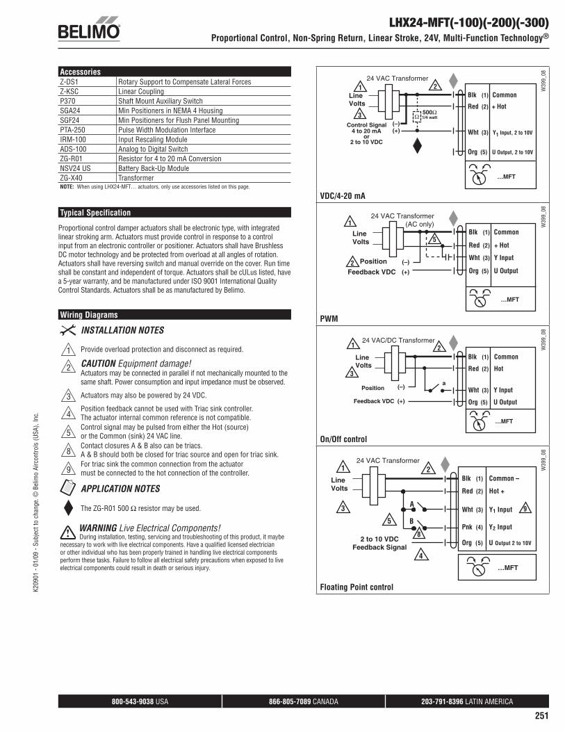
AccessoriesZ-DS1 Rotary Support to Compensate Lateral ForcesZ-KSC Linear CouplingP370 Shaft Mount Auxiliary SwitchSGA24 Min Positioners in NEMA 4 HousingSGF24 Min Positioners for Flush Panel MountingPTA-250 Pulse Width Modulation InterfaceIRM-100 Input Rescaling ModuleADS-100 Analog to Digital SwitchZG-R01 Resistor for 4 to 20 mA ConversionNSV24 US Battery Back-Up ModuleZG-X40 TransformerNOTE: When using LHX24-MFT… actuators, only use accessories listed on this page.
Typical Specification
Proportional control damper actuators shall be electronic type, with integrated linear stroking arm. Actuators must provide control in response to a control input from an electronic controller or positioner. Actuators shall have Brushless DC motor technology and be protected from overload at all angles of rotation. Actuators shall have reversing switch and manual override on the cover. Run time shall be constant and independent of torque. Actuators shall be cULus listed, have a 5-year warranty, and be manufactured under ISO 9001 International Quality Control Standards. Actuators shall be as manufactured by Belimo.
Wiring Diagrams
1 Provide overload protection and disconnect as required.
2 CAUTION Equipment damage!Actuators may be connected in parallel if not mechanically mounted to the same shaft. Power consumption and input impedance must be observed.
3 Actuators may also be powered by 24 VDC.
4Position feedback cannot be used with Triac sink controller. The actuator internal common reference is not compatible.
5Control signal may be pulsed from either the Hot (source) or the Common (sink) 24 VAC line.
8Contact closures A & B also can be triacs. A & B should both be closed for triac source and open for triac sink.
9For triac sink the common connection from the actuator must be connected to the hot connection of the controller.
The ZG-R01 500 resistor may be used.
WARNING Live Electrical Components! During installation, testing, servicing and troubleshooting of this product, it maybe
necessary to work with live electrical components. Have a qualified licensed electrician or other individual who has been properly trained in handling live electrical components perform these tasks. Failure to follow all electrical safety precautions when exposed to live electrical components could result in death or serious injury.
LHX24-MFT(-100)(-200)(-300)Proportional Control, Non-Spring Return, Linear Stroke, 24V, Multi-Function Technology®
W39
9_08
VDC/4-20 mA
W39
9_08
PWM
W39
9_08
On/Off control
W39
9_08
Floating Point control K20
901
- 01/
09 -
Subj
ect t
o ch
ange
. © B
elim
o Ai
rcon
trols
(USA
), In
c.

800-543-9038 USA 866-805-7089 CANADA 203-791-8396 LATIN AMERICA
252
LHQB(X)24-1-100On/Off Control, Non-Spring Return, Linear Stroke, 24V
Linear Force min. 22 lbf for control of damper surfaces up to 6 sq. ft.
ApplicationFor On/Off control of dampers in HVAC systems. Actuator sizing should be done in accordance with the damper manufacturer’s specifications.
OperationThe actuator is not provided with and does not require any limit switches, but is electronically protected against overload. The anti-rotation strap supplied with the actuator will prevent lateral movement.
The LHQB(X) provides 4” [100 mm] of linear stroke. The stroke of the gear rack can be adjusted on both sides in increments of 0.8” [20 mm] by means of the mechanical end stops.
When reaching the damper or actuator end position, the actuator automatically stops. The gears can be manually disengaged with a button on the actuator cover.
The LHQB(X)24-1-100 actuators use a sensorless Brushless DC motor, which is controlled by an Application Specific Integrated Circuit (ASIC). The ASIC monitors and controls the actuator’s rotation and provides a digital rotation sensing (DRS) function to prevent damage to the actuator in a stall condition. Power consumption is reduced in holding mode.
Dimensions (Inches [mm])
LHQ2
4_1
Technical Data LHQB(X)24-1-100Power Supply 24 VAC ± 20% 50/60 Hz
24 VDC ± 20%Power Consumption 12 W (1.5 W)Transformer Sizing 18 VA (Class 2 power source)Electrical Connection
LHQB24-1-100 3 ft [1m]18 GA plenum rated cableProtected NEMA 2 (IP54)
LHQX24-1-100 3 ft [1m] 10 ft [3m] 16 ft [5m] 18 GA plenum rated cableProtected NEMA 2 (IP54)
Overload Protection electronic throughout full strokeControl On/OffInput Impedance 1000 Feedback Output U 2 to 10 VDC (max 0.5 mA)
VDC VariableLinear Stroke 1.6” to 4.0” [40mm to 100 mm]Linear Force 22 lbf [100 Nm]Stroke Direction reversible with switchManual Override external push buttonRunning Time 3.5 seconds per 4” [100mm]Humidity 5 to 95% RH non condensing (EN 60730-1)Ambient Temperature -22°F to 122°F [-30°C to 50°C]Storage Temperature -40°F to 176°F [-40°C to 80°C]Housing NEMA 2, IP54, UL enclosure type 2Housing Material UL94-5VAAgency Listings cULus acc. to UL 60730-1A/-2-14,
CAN/CSA E60730-1:02,CE acc. to 2004/108/EEC and 2006/95/EC
Noise Level (max) <52 dB(A)Servicing maintenance freeQuality Standard ISO 9001Weight 1.4 lbs [640 g]† Rated Impulse Voltage 800V, Type of action 1.AA, Control Pollution Degree 3.
K20
901
- 01/
09 -
Subj
ect t
o ch
ange
. © B
elim
o Ai
rcon
trols
(USA
), In
c.
800-543-9038 USA 866-805-7089 CANADA 203-791-8396 LATIN AMERICA
253
AccessoriesZ-DS1 Rotary Support to Compensate Lateral ForcesZ-KSC Linear CouplingP370 Shaft Mount Auxiliary SwitchNOTE: When using LHQB(X)24-1… actuators, only use accessories listed on this page.
Typical Specification
On/Off control damper actuators shall be electronic type, with integrated linear stroking arm. Actuators shall have Brushless DC motor technology and be protected from overload at all positions of linear stroke. Actuators shall have reversing switch and manual override on the cover. Run time shall be constant and independent of torque. Actuators shall be cUL listed, have a 5-year warranty, and be manufactured under ISO 9001 International Quality Control Standards. Actuators shall be as manufactured by Belimo.
LHQB(X)24-1-100On/Off Control, Non-Spring Return, Linear Stroke, 24V
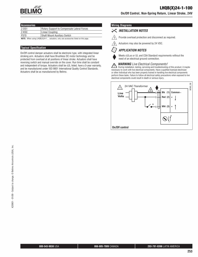
Wiring Diagrams
1 Provide overload protection and disconnect as required.
3 Actuators may also be powered by 24 VDC.
Meets cULus or UL and CSA Standard requirements without the need of an electrical ground connection.
WARNING Live Electrical Components! During installation, testing, servicing and troubleshooting of this product, it maybe
necessary to work with live electrical components. Have a qualified licensed electrician or other individual who has been properly trained in handling live electrical components perform these tasks. Failure to follow all electrical safety precautions when exposed to live electrical components could result in death or serious injury.
W39
3_08
On/Off control
K20
901
- 01/
09 -
Subj
ect t
o ch
ange
. © B
elim
o Ai
rcon
trols
(USA
), In
c.

800-543-9038 USA 866-805-7089 CANADA 203-791-8396 LATIN AMERICA
254
LHQB(X)24-MFT-100On/Off Control, Non-Spring Return, Linear Stroke, 24V
Linear Force min. 22 lbf for control of damper surfaces up to 6 sq. ft.
ApplicationFor proportional modulation of dampers in HVAC systems. Actuator sizing should be done in accordance with the damper manufacturer’s specifications.
The default parameters for 2 to 10 VDC applications of the …MFT actuator are assigned during manufacturing. If necessary, custom versions of the actuators can be ordered. The parameters can be changed by two means: pre-set and custom configurations from Belimo or on-site configurations using the Belimo PC-Tool software.
OperationThe actuator is not provided with and does not require and limit switches, but is electronically protected against overload. The anti-rotation strap supplied with the actuator will prevent lateral movement.
The LHQB(X) series provides 4” [100 mm] of linear stroke. The stroke of the gear rack can be adjusted on both sides in increments of 0.8” [20 mm] by means of the mechanical end stops.
When reaching the damper or actuator end position, the actuator automatically stops. The gears can be manually disengaged with a button on the actuator cover.
The LHQB(X)24-MFT-100 actuators use a sensorless brushless DC motor, which is controlled by an Application Specific Integrated Circuit (ASIC). The ASIC monitors and controls the actuator’s rotation and provides a digital rotation sensing (DRS) function to prevent damage to the actuator in a stall condition. Power consumption is reduced in holding mode.
Dimensions (Inches [mm])
LHQ2
4_M
FT
Technical Data LHQB(X)24-MFT-100Power Supply 24 VAC ± 20% 50/60 Hz
24 VDC ± 20%Power Consumption 12 W (1.5 W)Transformer Sizing 18 VA (Class 2 power source)Electrical Connection
LHQB24-MFT-100 3 ft [1m]18 GA plenum rated cable Protected NEMA 2 (IP54)
LHQX24-MFT-100 3 ft [1m] 10 ft [3m] 16 ft [5m] 18 GA plenum rated cable Protected NEMA 2 (IP54)
Overload Protection electronic throughout full strokeControl 2 to 10 VDC, 4 to 20 mA (default)
Variable (VDC, On/Off)Input Impedance 100 k (0.1 mA), 500 ,
1000 (On/Off)Feedback Output U 2 to 10 VDC (max 0.5 mA)
VDC VariableLinear Stroke 1.6” to 4.0” [40mm to 100 mm]Linear Force 22 lbf [100 Nm]Stroke Direction reversible with switchManual Override external push buttonRunning Time 3.5 seconds per 4” [100mm]
Variable (3.5, 5, 10 or 15 seconds)Humidity 5 to 95% RH non condensing (EN 60730-1)Ambient Temperature -22°F to 122°F [-30°C to 50°C]Storage Temperature -40°F to 176°F [-40°C to 80°C]Housing NEMA 2, IP54, UL enclosure type 2Housing Material UL94-5VAAgency Listings cULus acc. to UL 60730-1A/-2-14,
CAN/CSA E60730-1:02,CE acc. to 2004/108/EEC and 2006/95/EC
Noise Level (max) <52 dB(A)Servicing maintenance freeQuality Standard ISO 9001Weight 1.4 lbs [640 g]† Rated Impulse Voltage 800V, Type of action 1, Control Pollution Degree 3.
K20
901
- 01/
09 -
Subj
ect t
o ch
ange
. © B
elim
o Ai
rcon
trols
(USA
), In
c.

800-543-9038 USA 866-805-7089 CANADA 203-791-8396 LATIN AMERICA
255
AccessoriesZ-DS1 Rotary Support to Compensate Lateral ForcesZ-KSC Linear CouplingP370 Shaft Mount Auxiliary SwitchSGA24 Min Positioners in NEMA 4 HousingSGF24 Min Positioners for Flush Panel MountingPTA-250 Pulse Width Modulation InterfaceIRM-100 Input Rescaling ModuleADS-100 Analog to Digital SwitchZG-R01 Resistor for 4 to 20 mA ConversionNSV24 US Battery Back-Up ModuleZG-X40 TransformerNOTE: When using LHQB(X)24-MFT-100 actuators, only use accessories listed on this page.
Typical Specification
Proportional control damper actuators shall be electronic type, with integrated linear stroking arm. Actuators must provide control in response to a control input from an electronic controller or positioner. Actuators shall have Brushless DC motor technology and be protected from overload at all angles of rotation. Actuators shall have reversing switch and manual override on the cover. Run time shall be constant and independent of torque. Actuators shall be cULus listed, have a 5-year warranty, and be manufactured under ISO 9001 International Quality Control Standards. Actuators shall be as manufactured by Belimo.
LHQB(X)24-MFT-100On/Off Control, Non-Spring Return, Linear Stroke, 24V
Wiring Diagrams
1 Provide overload protection and disconnect as required.
2 CAUTION Equipment damage!Actuators may be connected in parallel if not mechanically mounted to the same shaft. Power consumption and input impedance must be observed.
3 Actuators may also be powered by 24 VDC.
4Control signal may be pulsed from either the Hot (source) or the Common (sink) 24 VAC line.
The ZG-R01 500 resistor may be used.
WARNING Live Electrical Components! During installation, testing, servicing and troubleshooting of this product, it maybe
necessary to work with live electrical components. Have a qualified licensed electrician or other individual who has been properly trained in handling live electrical components perform these tasks. Failure to follow all electrical safety precautions when exposed to live electrical components could result in death or serious injury.
W39
9_08
VDC/4-20 mA
W39
9_08
On/Off control
K20
901
- 01/
09 -
Subj
ect t
o ch
ange
. © B
elim
o Ai
rcon
trols
(USA
), In
c.