Embed Size (px)
Citation preview
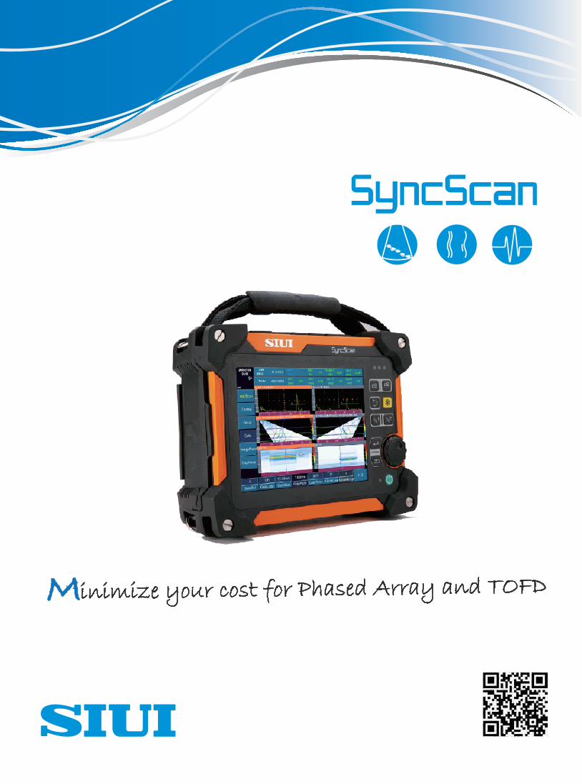
Minimize your cost for Phased Array and TOFD

Third-generation Phased Array flaw detector from SIUI, SyncScan incorporates the latest advancements in high-performance Phased Array and
TOFD detection into one compact unit. SyncScan can be upgraded with Phased Array and TOFD to satisfy various inspection requirements.
SyncScan can minimize your cost for Phased Array and TOFD inspection.
Superior Features
● High IP rate: IP65
● Light Weight: 3.75 kg with battery
● Large touch screen: 8.4" LCD with resolution 800×600 pixels
● Upgradeable from conventional UT to phased array or TOFD,
with powerful & complete optional software functions.
Reserved for Version Two:1/2/4-channel TOFD Probe
UT/TOFD ProbeEncoder In/Out
Phased Array Probe
Probe Locker
USB(2 pcs)EthernetSD Card
VGADC Power
Battery
Extendable connectors
Top View Side View (Right)Side View (Left)
Rubber Bumpers
90mm
8.4 inch
Compact and Durable
SyncScan is designed based on IP65 to suit the harshest
industrial environment. Extra-large 8.4-inch touch screen
can bring optimized experience for measurement and reading.
SyncScan is so compact (3.75kg, 90mm thickness) that
it can be operated with only one hand for aloft and field work.
*EN-12668-1 compliant
*Specific functions are subject to final order.
* Please define your preferred version before purchase.
Version Twoupgradeable to 1/2/4-ch TOFD/ UT
Conventional UT
Upgradeable from Conventional UT to Phased Array or TOFD
Touch Screen
Version Oneupgradeable to 16:64 PAUT + 1-ch TOFD/ UT

Conventional UT
Conventional UT
Advanced Functions:
API/ TCG/ AWS/ CSC/ B Scan/ Flat Weld Groove(RayTracing)/ Crack Height Measurement/ Probe Spectrum Analysis/ Cineloop
Basic Functions:
Velocity+Zero Calibration/ Angle Calibration/ DAC/ AVG(DGS)/Full screen A scan/ Coordinates switch (sound path, depth, horizontal)/
Surface compensation(xx+xxdB)/ Auto freeze/ Second leg color/ Auto gain/ Wave compare/ Wave filling/ Peak Envelope/ Screenshot
API 5UE AWS
B Scan Flat Weld Groove(RayTracing)
DAC
Full Screen A Scan
Thickness Measurement
Thickness MeasurementAdvanced function to achieve CoatTHK, Echo to Echo, B-scan, V PATH, TDG, TEMP and MULTI-Layers Measurement.
B-scanCoatTHK MULTI-Layers MeasurementTDG
TCG
Crack Height Measurement

Phased Array
PA Groups Function
Sensitivity Calibration Delay Calibration TCG Calibration
●To facilitate phased array operators, SyncScan carries calibration wizard with step-by-step guide to maximize inpection speed.
Velocity Calibration
Calibration Wizard
One phased array probe can be designated up to six groups for different inspection.
Multi groups of element and different angles can be applied for scanning at the same time, fully covering weld area and enhancing inspection
efficiency.
Two phased array probes can work simultaneously with phased array groups function to inspect both sides of the weld, enhancing the inspection
efficiency and speed.
Phased Array
Two Groups of A+B+C Scans Y Splitter for
two phased array probes
BEA Function(Backwall Echo Attenuator)This function is to help set a gate over an area and adjust the gain for this area
regardless of the global gain. It is very useful for inspection of Forgings and Castings
with allowing independent gain control of the area under the gate with the BEA for
backwall echo monitoring.

This function is to simulate flat plate work pieces geometry, including the beam coverage simulation and imaging parameter settings.
With this function, it will be easy to analyze, locate flaw signals.
Beam Coverage Simulation (Grouping) Beam Coverage Simulation(Single Probe) Flat Weld Groove
Phased Array
Flat Weld Groove(Flat Plate)
Flat Weld SolutionThis solution is suitable for flat butt weld and pipe girth weld inspection.
Automatically simulate various welds with different groove types to make simulation closer to the on-site weld shape.
Professional wizard operation mode facilitates operators finish phased array setup
Assisted positioning (RayTracing) flaw measurement and report generation functions are available.
Eight types of weld groove: V, Half V, Y, X, U, I, Y with backing, Asymmetric Welds.
Quick setup of weld parameters: thickness, material type, groove width, root clearance, up/down reinforcement, fusion simulation,
heat-affected zone, as well as workpiece edit, delete, add and rename.
Y-weld with backing Asymmetric Weld U-Weld Single V-Weld
New Weld Type Selection RayTracing (A+B+R scan)

Angle Weld Solution
Automatically simulate real angle weld shape based on parameters input.
Simulate sound beam coverage in six different probe positions.
When RayTracing function is on, the software can auto analyze and judge the workpiece
flaw situation, record flaw image and measurement result, and generate test report.
RayTracing (A+B+C+R scan)Web Simulation
Phased Array
Suitable for angle welds in ocean platform and oil & gas steel structure.
Simultaneous Inspection of PA & TOFD
TOFD Probes
Phased Array Probes
Simultaneous phased array and TOFD inspection can expand scanning coverage, decrease undetected rate.
Foldable Mechanism
Flange Simulation T-weld Simulation
Small Pipe Girth Weld Solution
Selection of Probes and Wedges Scan Type Setup Focal Law Setup Workpiece Setup
This solution is suitable for testing welds of small diameter pipes with outside diameters
ranging from 21-115mm (0.83-4.52 inch).
By offering features of V-groove and Y-groove weld making, beam coverage simulation,
as well as inserted wedge and link assembly guide table, the solution helps users to finish
testing of small diameter pipes quickly.

Easy to work out scan plan for pipeline corrosion inspection.
Step-by-step wizard can guide operators to finish setup easily
and improve inspection speed.
Different thickness will be displayed in different colors, making
it easier to determine corrosion situation for pipe.
Data analysis is available, for better understand the corrosion.
Phased Array
Corrosion Solution
Chain Phased Array Crawler (XY axis) Corrosion Solution
C Scan In-Amplitude, showing echo amplitude C Scan In-Depth, showing echo depth,
can be used for simple corrosion inspection.
Data Source
Flaws can be measured and analyzed PDF test report can be generated on the
SyncScan instrument.
Image Measurement & Report Generation
A-scan signal waveform and info (angle, south path, amplitude
and depth) for any position on the scan figure can be displayed
real time, and the operators may use two cross cursors to
measure flaw length and height on the B/C/D scans.
The measurement result and flaw images can be saved for
generating test report automatically.
PA Probe Element Testing
Probe Test Result Probe Test ReportProbe Test Interface
Conforming to ASTM E2491 code, this solution achieves auto testing of phased array equipment for its element activity, so as to measure
activity of all elements and acoustic energy uniformity of the phased array probe.

TOFD
With step-by-step menu to guide operators to finish TOFD scanning process easily and improve inspection speed.
Step 1: Setup channel number for inspection.Step 2: Workpiece coverage simulation.Step 3: Setup wave parameter.Step 4: Setup encoder parameter.Step 5: Setup image scanning parameter.
Beam Coverage Simulation
TOFD Wizard
Scanning Parameter Setting
TOFD Measurement
TOFD Measurement TOFD Measurement Result
Perform straightening, filter, local zoom, contrast adjustment, gain post processing and SAFT on the TOFD image.
TOFD
TOFD Image Processing
Raw TOFD Image
After SAFT
After Remove
SyncScan TOFD measurement is easy and useful.
The flaw height and length can be measured by moving
the reference line. The measurement result is clearly
shown in the data table.
TOFD Image Direction
Input weld parameters to set up the workpiece.Horizontal TOFD image Longitudinal TOFD image
Workpiece Setup
Blind Zone Inspection
TOFD+Conventional UT to inspect the blind zone area

Phased Array File Measurement TOFD File Measurement
Angle step
Focus
Scan angle(Linear)Channel 2
CalibrationProbe InfoProbe model
Frequency
Pitch
Element num
Probe length
Probe width
Probe heightWedge InfoWedge model
Angle
First element height
First element x
Vel
Wedge length
Wedge width
Wedge height
Setup InfoScan depth
Display delay
Pulse voltage
Pulse freq
Pulse power
PRF
Receive freq
Gain
Scan line num / frame
Echo type
Material vel
Scan type
Start element
End element
Linear step
Aperture
Start angle(Sector)
End angle(Sector)
Angle step
Focus
Scan angle(Linear)Images
Measurement
Remark
Operator
Signature
Date:
Ultrasonic Test ReportCompany
Workpiece SNSpecs Material SurfaceMethod CouplingStandard Class DateFile Info
File name File typeMachine Info
Machine Machine SNModule Module SNSoftware version Hardware versionGroupNumScanning Info
Frame num Scan modeScan time step Scan encode step
Scan encoder XMpp Scan encoder YMppEncoder Name
Channel 1Calibration
Probe InfoProbe model Frequency
Pitch Element numProbe length Probe widthProbe height
Wedge InfoWedge model Angle
First element height First element xVel Wedge length
Wedge width Wedge heightSetup InfoScan depth Display delay
Pulse voltage Pulse freqPulse power PRFReceive freq Gain
Scan line num / frame Echo typeMaterial vel Scan typeStart element End elementLinear step Aperture
Start angle(Sector) End angle(Sector)Angle step Focus
Scan angle(Linear)Channel 2
CalibrationProbe Info
Probe model FrequencyPitch Element num
Probe length Probe widthProbe height
Wedge InfoWedge model Angle
First element height First element x
Vel
Wedge length
Wedge width
Wedge height
Setup InfoScan depth
Display delay
Pulse voltage
Pulse freq
Pulse power
PRF
Receive freq
Gain
Scan line num / frame
Echo type
Material vel
Scan type
Start element
End element
Linear step
Aperture
Start angle(Sector)
End angle(Sector)
Angle step
Focus
Scan angle(Linear)
Images
Measurement
Remark
Operator
Signature
Date:
PC SoftwareMain functions: Checking data file, Screen capture, Measuring data analysis. Generating test reports in word or excel format.
Several files from corrosion solution can be opened and combined. Abundant report samples are available.
Report
Management
Easy-to-use interface to make work piece, probe, wedge, encoder and storage managements more convenient.In the work piece management, the shape of the work piece is simulated and detailed parameters are listed for reference.The operators may manage probe and wedge parameters via probe and wedge management.Follow the wizard, the operators can finish encoder simple operation, calibration and test quickly.Parameters, screenshot and data can be easily managed in the storage management to enhance the inspection efficiency.
Work Piece Management
Probe Management
Wedge Management
Encoder ManagementStorage Management
Application
SyncScan is designed to increase productivity in less demanding applications. It is suitable for inspection flaw position and size, which can be
widely used for various detection demands, such as PA weld inspection, TOFD weld inspection, corrosion mapping, composite inspection, gas
pressure welding on rail, pressure vessel inspection, stainless steel and PE pipe inspection...
UT File Measurement

Scan Wizard, Time Window
Technical Specification for 16:64 PAUT and TOFD to achieve simultaneous inspection of PA & TOFD
10
A/B A/B/D
PCS, Wedge Delay, PCS/Depth, Time Window, Probe ZeroZero, Velocity, Angle

Ra/ Da Ra/ Da
A, B, C, D, A+B, B+C, A+B+R,A+B+C+R...
BEA(Backwall Echo Attenuator)

DCY2.781.EN.SyncScan CY/6C07Specifications and appearance are subject to change without prior notice.
Shantou Institute of Ultrasonic Instruments Co., Ltd.
Add: #77, Jinsha Road, Shantou 515041, Guangdong, ChinaTel: +86-754-88250150 Fax: +86-754-88251499E-mail: [email protected] Website: http://www.siui.com
General Technical Specification
Input/Output
USB Connector 2 pcs
Ethernet Connector 1 pc
Video Output VGA port
Encoder Connector 1 pc (14-core)
Environment Tests
Operation Temperature -10℃-45℃
Storage Temperature -20℃-60℃
IP Code IP65