Embed Size (px)
Citation preview

MINIMALLY INVASIVE SCOLIOSIS SURGERY
FORCE APPLICATION DEVICE
Team 13
Kyle Cryderman Jeff Issner Mike Tanis Alex Was
Sponsor Surgeon
University of Michigan, Department of Neurosurgery
Section Instructor Professor Albert Shih

1
EXECUTIVE SUMMARY
Our sponsor, a neurosurgeon at the University of Michigan Medical Center, has asked our team to modify the current Jackson spinal surgery table. Being one of the few surgeons around the world to practice the minimally invasive technique in spinal surgeries, he is looking for a device that will assist him during corrective scoliosis surgery. He requested a device that can provide a force applied at three locations on the patient’s body to straighten the spine during surgery. Upon straightening, the surgeon will be able to insert the necessary rods into the patients back more easily, therefore, increasing the likelihood of a successful surgery and increasing his efficiency in the operating room. The mechanism must be able to support any size patient, provide the necessary push to better align the spine, and must not cause damage to the patient’s skin or internal organs. These customer requirements were translated into several engineering specifications. The device must have two degrees of freedom in order to adjust for patients of various sizes and to apply the force in the necessary direction. Human ribs have an ultimate stress of 124.4 MPa, and the skin experiences tissue damage from a stress of 6.7 to 13.3 kPa for extended periods of time [5,6]. These stresses act as boundaries for the maximum force our device will apply to the patient’s back, without injuring the patient. We developed several concepts during our design brainstorming sessions. Most of the concepts utilized a gear/ratchet system to transfer an easy, effective, and reliable force from the Dr.’s hand to the patient. However, during our concept selection process, a new idea was presented that took advantage of a much simpler mechanism. We investigated the benefits and drawbacks of each concept using a scoring system, applying the restrictions of the operating room. Concurrent with the concept analysis, we referred to our QFD that provided helpful weight/importance calculations based on customer requirement relationships. Due to its simplicity and manufacturability, our final concept incorporated something similar to a snowboard binding, so that Our sponsor could simply push on the device and feel how much force he is applying. A trigger locks into “teeth” when the necessary force is applied and the device applies a constant force until the surgeon releases it. CAD models were generated based on our design sketches. We performed a complete engineering analysis on all critical areas, a failure mode effect analysis, and a SimaPro environmental impact analysis. We then created a full working prototype made almost entirely of stainless steel 304 due to its high strength and corrosion resistant characteristics. The prototype was tested at the University of Michigan Hospital on a Jackson Table. Testing was successful and the prototype met all specifications.

2
PROBLEM DESCRIPTION Minimally invasive surgery is becoming the standard for many surgical procedures. The Department of Neurosurgery at the University of Michigan, along with our surgeon sponsor, is one of the few medical centers around the world to implement the minimally invasive technique during spinal surgeries. In the past, patients with scoliosis who underwent corrective surgery would have large amounts of scarring and muscle/tissue damage. With the new minimally invasive approach, the patient will experience less blood loss during the procedure, have a shorter recovery period, and fewer post-operation complications. Scoliosis correcting spinal surgery involves placing and screwing a rod within the spinal column to fuse the spine together in the best position for the patient in the long run. In the regular procedure, the surgeon would cut the back open along the spine, and insert the rod. With the minimally invasive technique, the surgeon must snake the rod through the spine from a small incision near the neck. He then uses a live computed tomography (CT) scan to screw the rods in place. Figure 1 shows a common case of a patient with scoliosis. Notice the distinct “S” shape of the column. This is what the Doctor must navigate the correcting rod through using only his intuition and a small fiber optic camera. As one can imagine, this is extremely difficult. Our sponsor has found that by applying a “push” force on the patient’s flank, hip, and ribcage, it is possible to make the patient’s spine have smaller curvature. If this process could be achieved in the operating room, it would be much easier for the surgeon to snake the rod down the patient’s spine. Figure 2 contains images taken by our team’s sponsor showing the straightening effect of applying a force on the patient’s side. Figure 1. Example of a patient with scoliosis (arrows represent three areas of the “push”: flank,
hip and ribcage) [1].

3
Figure 2. Typical case of patient with scoliosis (left). Applying a “push” causes the spine to align (middle). Scoliosis correcting surgery is completed (right). [12]
Our team’s problem is that the table currently used in the operating room cannot assist the surgeon in aligning the spine for rod placement. Our sponsor has requested that we create a device that can used to align the spine without requiring extra assistance in the operating room. The design must create multiple points of contact on the patient’s torso, provide a constant force, and be easily adjustable along the axis of the table. RELATED PRODUCTS AND TECHNOLOGIES There are currently two major surgery tables used for spinal operations, the Jackson Table and the Allen® FLEX FRAME™ Spinal System. Both of these tables are very versatile and can be used for many different operations. Jackson Spinal with Advanced Control Pad System™ [2] The Jackson Spinal System, produced by Mizuho OSI, is the most popular table for spinal surgery. The table, shown in Figure 3, consists of a modular table base and the actual Jackson spinal table top. The table top has a length of 84 in. and a width of 17 in. The modular table base has a length of 102 in., a width of 32 in., and can be raised to heights between 27 in. and 48 in. The maximum patient weight capacity for the Jackson table is 500 lb.

4
Figure 3. The Jackson Spinal System, consisting of a modular base and a spinal table attachment, has different configurations for various spinal surgeries. [2]
One of the more important features of the Jackson Spinal System is that it allows x-rays to be taken in many different positions during surgery. The table uses a radiolucent frame, composed of carbon composite. The table can be tilted and rotated in various ways, allowing a C-arm, a device used for taking x-rays during surgery, to be completely integrated. The table allows for 10 degrees of rotation about the hips and 360 degrees of rotation about the spinal axis. This not only provides x-ray integration but allows safe rotation of the patient during spinal fusion surgery. Five support cushions are strategically placed on the Jackson Spinal System to optimize patient comfort and to minimize blood loss during surgery. The manufacturer claims to reduce vena caval compression, maximizing blood flow from the lower half of the body to the heart and minimizing epidural venus bleeding. [2] Allen® FLEX FRAME™ Spinal System [3,4] The Allen® FLEX FRAME™ Spinal System, produced by Allen Medical Systems, is an attachment for a standard operating table. The table attaches to the current table in three steps, as shown in Figure 4, below. Figure 4. The Allen® FLEX FRAME™ Spinal System attaches to the standard operating table in
three steps. [3]

5
Like the Jackson Spinal System, the Allen System allows for C-arm integration and is completely radiolucent for imaging. The system uses power from the current operating table to move from a position of extreme lordosis to kyphosis for diverse operations, as shown in Figure 5. Figure 5. The Allen System uses the power from the current operating table to move from
extreme lordosis to extreme reverse lordosis. [4]
The Allen system may be tilted laterally 20º and flexed 20º. The frame width is 17 in. and the height may be adjusted from 25 in. to 38 in. The system is designed to hold patients that weigh up to 400 lb. It fits on OR tables with outside rail widths of 20 in. to 24 in and is compatible with most Jackson Spinal System accessories. [4] Allen® Wing-Set™ Allen Medical Systems also produces the Allen® Wing-Set™, shown in Figure 6. The Wing-Set™ provides patient support while still allowing a free abdomen and can be attached to either the Jackson table or Allen system. The supports can be adjusted to widths of 10-18 in. and angles of ±25K to provide maximum comfort and minimize bleeding for large and small patients as well as patients with scoliosis or other spinal disorders. Figure 6. The Allen® Wing-Set™ adjusts to provide proper patient support for patients with
various spinal disorders and patients of various sizes. [3]

6
CUSTOMER REQUIREMENTS AND ENGINEERING SPECIFICATIONS The modifications to the existing Jackson Spinal System that our group is planning will focus on the application of a controlled force in three locations along the side of the patient’s torso. Prior to surgery, each scoliosis patient will be anesthetized, and placed on the Jackson table on his/her stomach. Our goal is to comfortably apply a controlled force at the flank and hip on one side of the patient, and an opposing force near the rib-cage on the other side of the patient. The pressure from these applied forces will straighten the spine of the patient prior to surgery, allowing the minimally invasive scoliosis surgery to run more efficiently than the current procedures used to straighten the spine for scoliosis patients. The surgical table will be produced through the combination of customer requirements from our sponsor, and our technical design experience. This project is entirely a product of customer requirements, and our group’s ability to convert those requirements into engineering targets. Therefore, we place great importance on the requests and requirements from the neurosurgery staff at the University of Michigan Medical Center. Our team sat down and attempted to translate the requirements and requests of our sponsor into engineering targets. Using the technical knowledge of design and manufacturing that we have gained in our previous courses, we converted each requirement into an engineering target that we believed was manageable. We recognize that some of the engineering targets will be changed due to cost of production, manufacturing conditions, and other various reasons, however, we are prepared to alter any target if the project or our sponsor requires such action.Within the requests from Our sponsor and his staff, our group had to determine which were most important to focus on. We determined importance by evaluating each requirement to understand if the requirement significantly improved efficiency in the operating room and was one that our group could translate into an engineering target to design and build. To illustrate the relationship between our sponsor requirements and our engineering specifications, a QFD was made, and can be seen in Appendix A. The QFD was created using our desired requirements for the surgical table from our sponsor and listing them vertically on the left side of the chart. Along the top of the QFD, our engineering specifications were listed. Each design requirement was evaluated against the engineering specifications based on their relationship (strong, weak, or no relationship). This allowed our group to quantify, based on a points system, how important each design requirement is compared with the others. We also quantified how capable our group is, on a scale from 1-10, of designing and producing components with the engineering specifications listed in the QFD. All of these design characteristic evaluations gave our group a better idea of how we should be managing our time. The purpose of the QFD is to provide an easy to read list of design requirements and to then quantify their relative importance based on their strength of relationship with the engineering specifications our group has determined. Table 1, on the next page, shows how our customer requirements relate to our engineering specifications. We determined that two degrees of freedom were needed for the pads to accommodate patients of varying height and weight. We decided that a maximum force application height of 18 inches and a minimum height of 6 inches from the Jackson System

7
frame would be acceptable. We also found that a 75 lb force applied at the rib-cage, shoulder, and hip, will effectively straighten the patient’s spine to more efficiently complete the minimally invasive procedure, as determined from a meeting between our group and Our sponsor. Our team is working to create a device that can apply such a force to the patient for as long as 1 hour. The estimate of 75 lb is a benchmark for evaluation of the effects of force on the patient’s skin and rib-cage for extended periods of time. 75 lb of force translates to approximately 300 N. A study completed at the Center for Injury Biomechanics at Virginia Tech examined the structural properties of human rib cortical bone. Corticol bone is the protective outer layer of the bone structure. It was determined that the ultimate stress of human rib cortical bone is 124.2 MPa [5]. This value will help us determine the maximum force our sponsor and his team can apply to the patient’s rib cage during surgery without damaging the internal bone structure of his patients. Long-term applications of pressure can potentially lead to tissue damage with varying severity. It has been shown that a pressure of 6.7 and 13.3 kPa applied for 20 hours to the human epidermis can lead to severe tissue damage [6]. Short term pressure (2 hour) applications of these forces showed no damage to the tissue membrane [6]. Our team will work to minimize the amount of time the pressure will be applied to the patient during surgery by designing a device that will shorten Our sponsor’s surgeries. Table 1. Customer requirements were translated by our team into engineering targets.
Customer Requirement Engineering Target Unit of Measurement Force applied at hip, flank,
and rib-cage ~ 300 Newtons
Cannot exceed rib-cage fracture stress
124.4 MPa
Cannot exceed pressure where tissue damage occurs
6.7 to 13.3 kPa
Ability to change positions of supporting pads to fit various
heights and widths
2 degrees of freedom D.O.F.
Maximum/Minimum Height 18/6 inches PROBLEM ANALYSIS The nature of the minimally invasive scoliosis surgery Jackson Spinal System adaptation requires the utilization of several engineering disciplines as well as some insight into the medical profession. Fortunately, Our sponsor will provide the necessary medical information for our team. Each of his requests and recommendations requires that a surgical need is translated into engineering specifications through our knowledge and experience. The primary objective of the group is to design an attachment for the Jackson Table that can apply sustainable forces on a patient. As per Our sponsor’s specification, the device must not exert too much pressure on the patient. Therefore, we must keep static forces in mind when

8
designing the support pads, for if the applicable area is too small, the pressure could exceed healthy limits (13.3 kPa over 2 hours). The mechanical behavior of materials and basic physics must be taken into account when designing the mechanical apparatus such that it will not fail under a load of ~300 N. As the structure must both apply and translate a considerable force, stress concentrations and failure points must be considered and materials must be chosen accordingly. Designing the Jackson Table addition provides many challenges, some of which stem from the strict conditions that exist in the operating room. Since the operating room requires unthinkable levels of cleanliness to prevent infection, our concept must be easy to clean, involve few small crevices where fluid could collect, and not react to sterilization chemicals. Because of this, it is preferable to work with surgical steel or carbon fiber, though we still have to explore the feasibility of these materials. Our sponsor has informed us that the device being radiolucent will not be an issue. He will be able to remove the device by the time that he needs to take the necessary images. Furthermore, the apparatus must not interfere with the surgeon’s ability to operate on the patient. Therefore, our preliminary concepts all attempt to utilize compact, self contained means of operation. Other challenges include attaching our design to the current table, determining the proper means of applying a force, and working around the existing parts of the table. Our preliminary designs offer different solutions to these problems.. CONCEPT GENERATION AND PRELIMINARY IDEAS After taking the requests of Our sponsor, and turning them into engineering specifications, our team had three main goals for the design we would come up with. The design needs to provide a force to straighten the spine during the procedure, cause no damage to the patient’s skin or internal organs, and have at least two degrees of freedom (move along the length of the table and perpendicular to it). With these requirements in mind, our team discussed several preliminary ideas and began to brainstorm. We decided to take the IDEO approach to designing as each team member came up with two or more unique design ideas. At our next meeting, the initial designs were displayed and explained by there creator. One of our biggest concerns, while reviewing the concepts, was to create a design that could be made compact enough so that it would not interfere with the surgical staff. We discussed issues such as ease of use, feasibility, size, strength of mechanism, and convenience for the operating room staff, narrowing down our top designs. All of our concept designs described can be seen on the next page in Figure 7, and on a larger scale in Appendix C. Figure 7. Five initial designs created by our group.

9
Design 1 utilizes two different mechanisms to move the pad toward the body: a spring button, such as the mechanism used
Concept 1 Concept 2
Concept 3 Concept 4
Concept 5
10
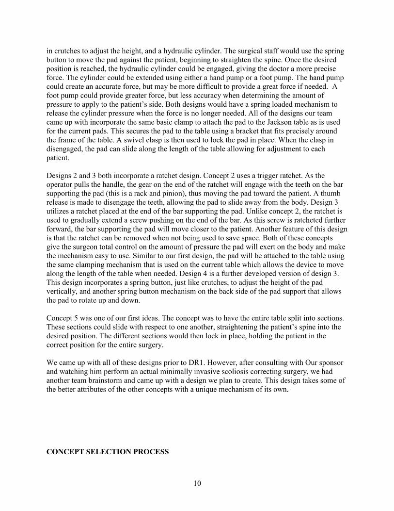
in crutches to adjust the height, and a hydraulic cylinder. The surgical staff would use the spring button to move the pad against the patient, beginning to straighten the spine. Once the desired position is reached, the hydraulic cylinder could be engaged, giving the doctor a more precise force. The cylinder could be extended using either a hand pump or a foot pump. The hand pump could create an accurate force, but may be more difficult to provide a great force if needed. A foot pump could provide greater force, but less accuracy when determining the amount of pressure to apply to the patient’s side. Both designs would have a spring loaded mechanism to release the cylinder pressure when the force is no longer needed. All of the designs our team came up with incorporate the same basic clamp to attach the pad to the Jackson table as is used for the current pads. This secures the pad to the table using a bracket that fits precisely around the frame of the table. A swivel clasp is then used to lock the pad in place. When the clasp in disengaged, the pad can slide along the length of the table allowing for adjustment to each patient. Designs 2 and 3 both incorporate a ratchet design. Concept 2 uses a trigger ratchet. As the operator pulls the handle, the gear on the end of the ratchet will engage with the teeth on the bar supporting the pad (this is a rack and pinion), thus moving the pad toward the patient. A thumb release is made to disengage the teeth, allowing the pad to slide away from the body. Design 3 utilizes a ratchet placed at the end of the bar supporting the pad. Unlike concept 2, the ratchet is used to gradually extend a screw pushing on the end of the bar. As this screw is ratcheted further forward, the bar supporting the pad will move closer to the patient. Another feature of this design is that the ratchet can be removed when not being used to save space. Both of these concepts give the surgeon total control on the amount of pressure the pad will exert on the body and make the mechanism easy to use. Similar to our first design, the pad will be attached to the table using the same clamping mechanism that is used on the current table which allows the device to move along the length of the table when needed. Design 4 is a further developed version of design 3. This design incorporates a spring button, just like crutches, to adjust the height of the pad vertically, and another spring button mechanism on the back side of the pad support that allows the pad to rotate up and down. Concept 5 was one of our first ideas. The concept was to have the entire table split into sections. These sections could slide with respect to one another, straightening the patient’s spine into the desired position. The different sections would then lock in place, holding the patient in the correct position for the entire surgery. We came up with all of these designs prior to DR1. However, after consulting with Our sponsor and watching him perform an actual minimally invasive scoliosis correcting surgery, we had another team brainstorm and came up with a design we plan to create. This design takes some of the better attributes of the other concepts with a unique mechanism of its own. CONCEPT SELECTION PROCESS

11
Being that we do not have very many engineering specifications and customer requirements to meet, a majority of our designs would have been capable of meeting our goals. Therefore, to select our final design, we focused on four main things while keeping our engineering specifications in mind. Our mechanism needed to be easy to use, easy to manufacture (keep production costs down), compact enough so that it would not interfere with the surgical staff, and easy to disassemble and fix if anything were to go wrong. From these requirements, we came up with a weighting system. Taking a look at our concepts, we went through each need (ease of use, manufacturability, compact and easy to fix) and gave each concept a grade between 1 and 5, with 1 being the worst, and 5 being the best. A total score of 20 would be the best possible score. The actual scoring system our team used can be seen in Table 2. Please refer to this table for our team’s alpha design decision making process. Concept 1 is a great idea. The combination of the spring button mechanism and the hydraulic cylinder, powered either by a hand or a foot, would provide an ultra precise force that the surgeon could apply to the patient. But, having hydraulic fluid in such a device would not be the safest alternative and could pose major problems if failure occurs. Another drawback to the hydraulic fluid concept is that Our sponsor wouldn’t be able to physically “feel” how much force he’s applying, he would only be able to feel the resistance of the hand pump. Without knowing how much force he’s applying to the patient’s side, he could potentially injure the patient during surgery with this design. This being one of our team’s more complex designs, fixing the device in an emergency may not even be possible for the surgical staff. There would also be a problem with the pumps themselves. These would have to be placed in an area that would not impede on the surgeons or nurses. With so little space in operating room already, adding an extra device to hang from the table may not be possible. This design, however, would be capable of producing a very large force with very little effort from the surgeon. Concept 1 received a score of 10/20 in our weighting system, making it our least voted on device. The two ratchet designs are fairly simple. Both concepts make providing a large force easy on the operator, and, like the hydraulic idea, create a precise push on the patient at the point of contact. Another positive feature of these designs is their compact size. The trigger ratchet, in concept 2, is placed underneath the bar that supports the pad, and the end ratchet, in concept 3, can be removed after the pad is in the desired position. These would very easy to control and reliable. The problem with these designs involves manufacturability. The rack and pinion for design 2 would have to be robust enough to handle large forces. To create or find a mechanism that can do this may not be plausible. Design 3 calls for an intricate combination of a ratchet and screw to push the pad forward. While both of these ideas are feasible, production costs would be higher than what we are looking for. Along with inflated production costs, the device would be relatively hard to clean, and be difficult to disassemble. Concepts 2 and 3 both received a score of 13/20 in our weighting system, thus eliminating them from alpha design contention. Concept 4 brought in two additional degrees of freedom for the pad. This design, like the previous three, could move along the length of the table, but also incorporated vertical height adjustment and rotational movement for the pad (both using a spring button mechanism). A big attribute of this design was the hand screw. This would move the pad toward or away from the patient, providing the operator complete control over the amount of pressure applied. Again, a

12
drawback of having this much control is that Our sponsor would not be able to feel the amount of pressure he’s applying to the device/patient. This could lead to too much force being applied to the patient, causing unwanted tissue or nerve damage. The problem with this design was its feasibility. We would have to manufacture the device so that as the screw turned, the pad did not rotate with it. Our team decided that this concept, because of the pad-screw mechanism, was too complex to try and utilize in our short time frame, and our scoring system confirmed our decision as this concept only received a score of 11/20 in our weighting system. We did not pursue the fifth concept for numerous reasons. First, and most importantly, the design was not very plausible. There is no need to completely redesign the table because the current table is very effective. We realized very quickly that designing a new attachment for the current table would not only be more cost effective, but easier to integrate into the operating room. Also, the idea is not very flexible. The table would only be able to correct certain spine shapes on patients of certain sizes. The concept lacks any vertical adjustments for patients who are positioned higher in the table. If you are too big for this table, you simply cannot be operated on. This design idea was quickly put to rest as it only received a score of 12/20 in our concept selection weighting system. Our alpha design, discussed in the next section, received a score of 19/20. This is the best score out of our initial concepts and was a clear choice for our alpha design. Table 2. The concept that received the best score in our weighting system was our alpha design
(19/20). A score of 20 is the best possible score.
CONCEPT EASE OF USE
EASY TO MANUFACTURE COMPACT EASY
TO FIX TOTAL
#1 (Hydraulic Pump) 3 3 3 1 10 #2 (End Ratchet) 4 2 5 2 13 #3 (Pull Ratchet) 4 2 5 2 13 #4 (Hand Screw) 4 1 5 1 11 #5 (Table Design) 3 1 5 3 12 #6 (Alpha Design) 5 5 4 5 19 ALPHA DESIGN On September 30th, 2008, our team was able to witness a minimally invasive scoliosis surgery. This event gave us new insight into the project and changed our course of action. Using our first-hand surgery experience with the table, we created a new concept that would better suit Our sponsor’s needs. This alpha design can be seen in Figure 8, and in more detail in Appendix D.

13
Figure 8. An isometric view of our team’s alpha design.
This concept uses the idea of a self-locking, sliding rail derived from a snowboard binding. The motivation behind this design was to be as simple, reliable, and adjustable as possible, but also satisfy our observations from the operating room. While watching the minimally invasive procedure, we noticed that the doctor is quite capable of supplying the forces needed to straighten the spine, so no mechanical advantage would be needed. We also took note of the little space available for the apparatus. Taking both items into account, we decided to use a toothed beam that would be pushed through a bracket from behind to apply the force on the patient. This beam requires less space and fewer components than some of our other concepts and could be created out of radiolucent materials such as carbon fiber and polymers. Most importantly, this design allows the doctor to have a better “feel” for how much force he/she is applying. Instead of a screw or pump design, the amount of force the surgeon applies on this design’s handle is exactly translated to the patient’s body. An important aspect of the design is the locking mechanism, which can be compared to a snowboard binding or roller coaster safety lock. The beam has teeth machined into the top surface and is allowed to pass through a bracket. As the rail passes through, a jointed follower clicks over each tooth, allowing forward motion, but forbidding the beam to slide backwards. In this way, the doctor can push until the spine is straight, then let go and allow the mechanism to sustain the necessary force. A handle similar to that found on a snow-shovel would be attached to one end of the mechanism, and a body-contoured pad to the other.
Surgeon force
Force on patient
Locking/release mechanism

14
While in the operating room, we also realized that the mechanism must be adjustable along the vertical axis, as people of different sizes fit uniquely on the table. The force of the push needs to be placed exactly at the patient’s ribcage. The force of the push will not be effective if it is angled upwards, or downwards due to the patient not fitting on the table correctly. Thus, the patient’s spine won’t be corrected to the degree necessary for Our sponsor. We made the vertical beam adjustable to fit patients of various heights and weights. To provide this degree of freedom, we have designed the vertical shaft to be comprised of two sections. Both will be made of rectangular tubing, however, the top section would be large enough to slide over the bottom section, with holes drilled into one side, at increments that are to be determined. The bottom segment would have a spring button attached that would be lined up with the holes of the top half. This is more effective than a screw because spring buttons require much less time to disengage. The spring button can be engaged and released in a matter of seconds, as opposed to a normal screw that requires time to adjust. The purpose of this device is to save time in surgery. Therefore, we tried to minimize the time Our sponsor would need to adjust his surgical device. Together, the two would be able to adjust to people of varying sizes. The bottom segment of the vertical support would be attached to a bracket that would surround the side rail of the Jackson Table. The top and sides of the bracket would be stationary, but the bottom would swivel around a bolt, allowing for easy removal. FINAL DESIGN DESCRIPTION After careful consideration, we have modified the alpha design to be stronger, more robust and incorporate higher ranges of variability, while maximizing the use of commonly available parts. Modifications were made to the alpha design so that its structure can withstand the given forces within a safety factor of 2 and the majority of its components can be easily machined from available steel stock. Furthermore, the vertical adjustment bar of the alpha design was found to be inadequately variable, and was, therefore, replaced with a new, more functional system. Also, we needed to modify the attachment method to the Jackson Table so that the device could fit around existing pads. A layout of the design can be seen in Figure 9. Dimensions for this figure and all other dimensioned drawings are in inches. A bill of materials can be found in Appendix E, complete with suppliers and prices for all materials. Manufacturing costs, however, are yet to be determined.

15
Figure 9. Layout of full design
The design looks much like the letter C. The bottom of the C attaches to the Jackson table side rail and is able to clamp to the table. The back side of the C is a vertically adjustable bar with a push-pin locking scheme. This allows for the unit to become “taller” or “shorter” in order to fit patients of different sizes. The top of the C is a horizontally adjustable toothed beam that, when pushed towards the patient, straightens the spine and locks in place via a latching mechanism, as described in the Alpha Design section. 1. Toothed Horizontal Beam The primary component of the design is the horizontal toothed beam, as seen in Figure 10. It is a ¾”x ¾”x12” solid stock bar that has twenty-eight ¼” tall, 45˚ teeth machined into its top surface. The teeth will provide 9.5” of horizontally locking adjustment. Furthermore, a 9/32” through hole is to be placed ½” from each end to accommodate ¼” lock pins for attaching the handle and pad.
Part 3: Push Handle
Part 5: Tooth Lock
Trigger
Part 4: Horizontal Translation
Bracket, Trigger Bracket, and Vertical
Adjustment Bar
Part 6: Vertical Translation
Bracket and “C” Bracket
Part 2: Pad and Pad
Mount Part 1: Toothed
Horizontal Beam

16
Figure 10. Toothed horizontal beam (all dimensions in inches)
2. Pad and Pad Mount The pad will be 6” wide, 4” tall, and 4”. The pad is to be made of 3 layers. The first layer is of 1” thick Minicel foam. This foam is rather stiff, and will provide a firm surface without compromising the patient’s safety. The other 2 layers are to be constructed from 1” thick polyfoam. The foam pad will be enclosed with a vinyl sheet covering, and will be attached to a 6” x 4” x ¼” steel plate using an epoxy compound. Additionally, a 1” section of 1” x 1” square machined tube will be welded concentrically to the plate. This section will include a 9/32” through hole for attachment by push-button pin to the toothed beam. This setup can be seen in Figure 11.
Pad
Push Handle

17
Figure 11. Pad and toothed beam attachment (all dimensions in inches)
3. Push Handle On the opposite end of the toothed beam, a handle will be attached using an identical piece of 1”x1” square machined stainless steel tubing, a through hole and a push-button pin (Figure 12). A 2”x2”x ¼” plate will then be welded concentrically to the tubing, creating a push pad. The dimensions of this handle are meant to match the approximate dimensions of a human palm, as it would be where the physician applies the push force. Figure 12. Push handle (all dimensions in inches)
18
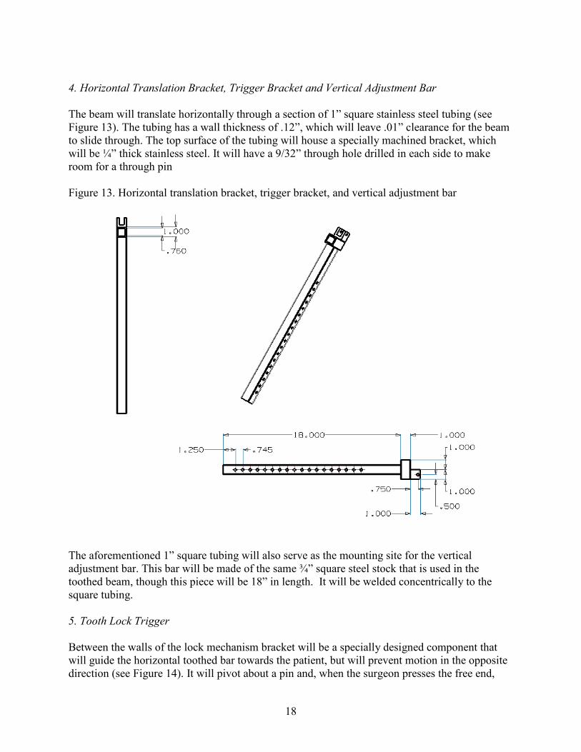
4. Horizontal Translation Bracket, Trigger Bracket and Vertical Adjustment Bar The beam will translate horizontally through a section of 1” square stainless steel tubing (see Figure 13). The tubing has a wall thickness of .12”, which will leave .01” clearance for the beam to slide through. The top surface of the tubing will house a specially machined bracket, which will be ¼” thick stainless steel. It will have a 9/32” through hole drilled in each side to make room for a through pin Figure 13. Horizontal translation bracket, trigger bracket, and vertical adjustment bar
The aforementioned 1” square tubing will also serve as the mounting site for the vertical adjustment bar. This bar will be made of the same ¾” square steel stock that is used in the toothed beam, though this piece will be 18” in length. It will be welded concentrically to the square tubing. 5. Tooth Lock Trigger Between the walls of the lock mechanism bracket will be a specially designed component that will guide the horizontal toothed bar towards the patient, but will prevent motion in the opposite direction (see Figure 14). It will pivot about a pin and, when the surgeon presses the free end,

19
will release, allowing the pressure to be taken off of the patient. This piece is to be made of ½” stainless steel and will contain a 9/32” through hole that corresponds concentrically to the hole in the lock mechanism bracket. The tooth lock mechanism can be fabricated using a band saw and drill press. Figure 14. Tooth lock trigger (all dimensions in inches)
6. Vertical Translation Bracket and “C-Bracket” The lower end of the vertical adjustment bar will translate vertically through another section of 1”x 1” square tubing (see Figure 15). Once again, the wall thickness is .12” and will provide clearance for translation. Furthermore, the beam will contain 18 through holes spaced 1” apart and the lower tubing bracket will share a similar hole so that a desired height can be set using a push-button lock pin.

20
Figure 15. Lower “C” bracket (all dimensions in inches)
The vertical adjustment bracket will be welded to an 8” long horizontal 1” solid square bar, set parallel to the table rail. That bar will be welded to two 2” long 1” square perpendicular bars, set at the ends. Two brackets must then be welded to the C-bracket, which will be used for attachment to the Jackson table. Each bracket will be band sawed and oversized, such that the vertical sides overlap the beam of the table. A 9/32” through hole will be placed just below where the bracket overlaps the table. Pins will then be placed through the holes to provide quick, easy attachment. Once constructed, the finished assembly will be able to adjust to a wide variety of patients, apply up to a 75 lb force on a patient’ side, lock in place, and release pressure when necessary. Extensive use of simple sliding and pinning mechanisms has made for a very compact design that is adjustable in both the vertical and horizontal directions. While the alpha design was theoretically sound, it was impractical to build considering its non-standard dimensions. By researching available material sizes prior to re-designing, we were able to create a final design that would be far easier to manufacture, yet was able to capitalize on many of the important ideas contained in the alpha design. For example, the alpha design included the use of beams sliding through sections of square tubing. However, the proposed dimensions were highly unattainable and could not be used. Therefore, square machined tubing and related sliding bars were carefully chosen from readily available McMaster-Carr stock. Wall thicknesses, tolerances and stress bearing capabilities were all taken into account before the model was designed.

21
Dimensions also impacted the stress analysis of our final design. To ensure that our final design would not fail under load, the group performed stress analyses on several essential components. The final design was then created such that no part would fail, even with twice the intended load. Lastly, the final design was created to work properly, to be robust, as well as maintaining a high ease of use. Longevity of design is a major problem with medical components, as they are subject to harsh sterilization practices. Therefore, we designed the entire apparatus out of corrosion-resistant stainless steel, less the pad. We made the device very simple which helped make it easy to use, disassemble, and fix, if necessary. STRESS ANALYSIS OF FINAL DESIGN Before beginning the manufacturing process, we thoroughly checked key areas of our design to ensure that they would not fail during use. See Appendix F for complete engineering calculations. Throughout the stress analysis, refer to Figure 16 below. If all of these key areas pass our stress analysis, the entire device will not fail. Figure 16. Each key area of the design is labeled with a number. The device will not fail if these key areas pass the stress analysis.
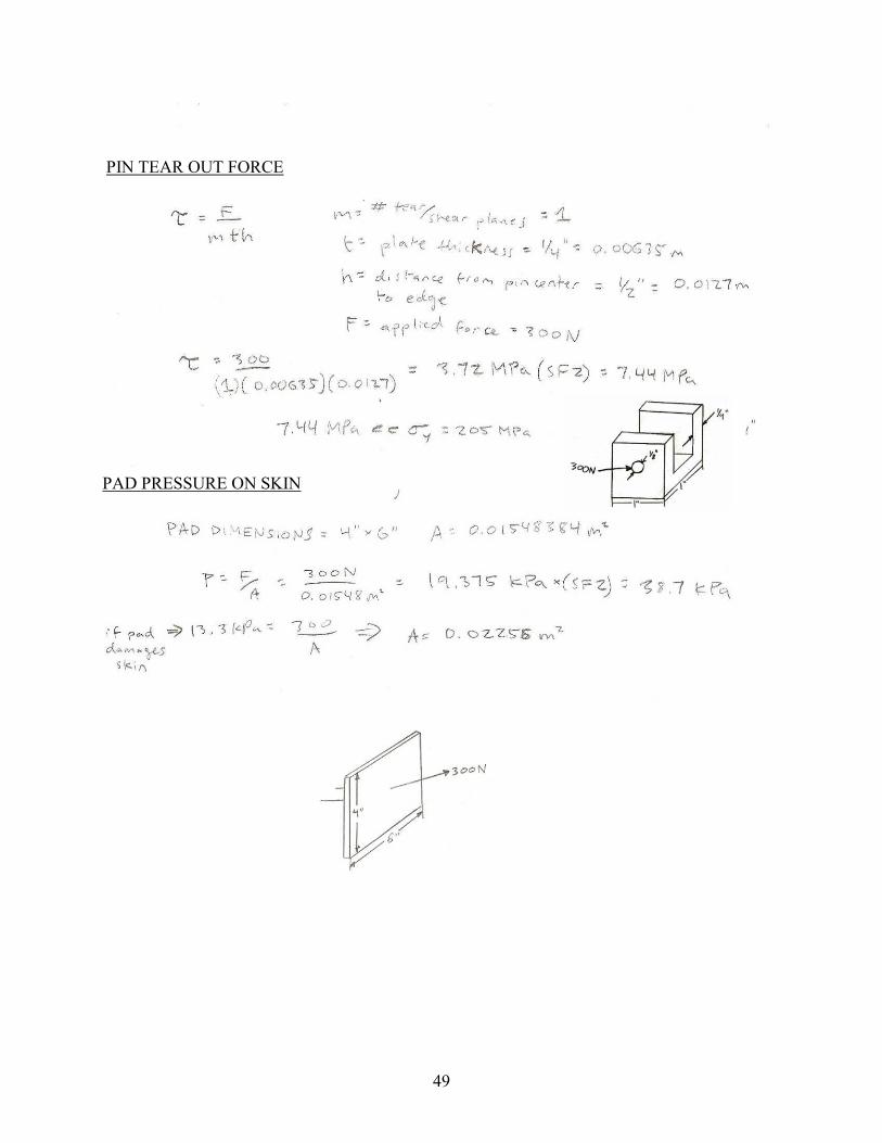
Pad Pressure on Patient A long term application of pressure on a patient’s skin can cause permanent damage. We had to make sure that the pad would not damage the patient’s skin during surgery. The location of this force is labeled “1” in Figure 16, above. Previous work has shown that a pressure of 13.3 kPa can be applied to the skin for two hours without any tissue damage [6]. In the actual prototype,
1
3 2
4
22
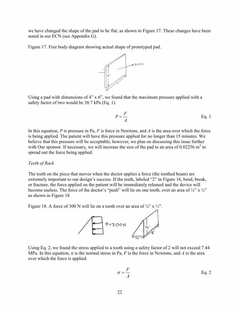
we have changed the shape of the pad to be flat, as shown in Figure 17. These changes have been noted in our ECN (see Appendix G). Figure 17. Free body diagram showing actual shape of prototyped pad.
Using a pad with dimensions of 4” x 6”, we found that the maximum pressure applied with a safety factor of two would be 38.7 kPa (Eq. 1).
AF
P = Eq. 1
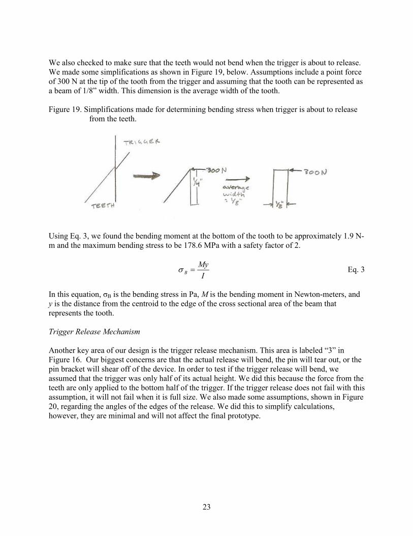
In this equation, P is pressure in Pa, F is force in Newtons, and A is the area over which the force is being applied. The patient will have this pressure applied for no longer than 15 minutes. We believe that this pressure will be acceptable; however, we plan on discussing this issue further with Our sponsor. If necessary, we will increase the size of the pad to an area of 0.02256 m2 to spread out the force being applied. Teeth of Rack The teeth on the piece that moves when the doctor applies a force (the toothed beam) are extremely important to our design’s success. If the teeth, labeled “2” in Figure 16, bend, break, or fracture, the force applied on the patient will be immediately released and the device will become useless. The force of the doctor’s “push” will lie on one tooth, over an area of ¼” x ½” as shown in Figure 18. Figure 18. A force of 300 N will lie on a tooth over an area of ¼” x ½”.
Using Eq. 2, we found the stress applied to a tooth using a safety factor of 2 will not exceed 7.44 MPa. In this equation, σ is the normal stress in Pa, F is the force in Newtons, and A is the area over which the force is applied.
AF
=σ Eq. 2
23
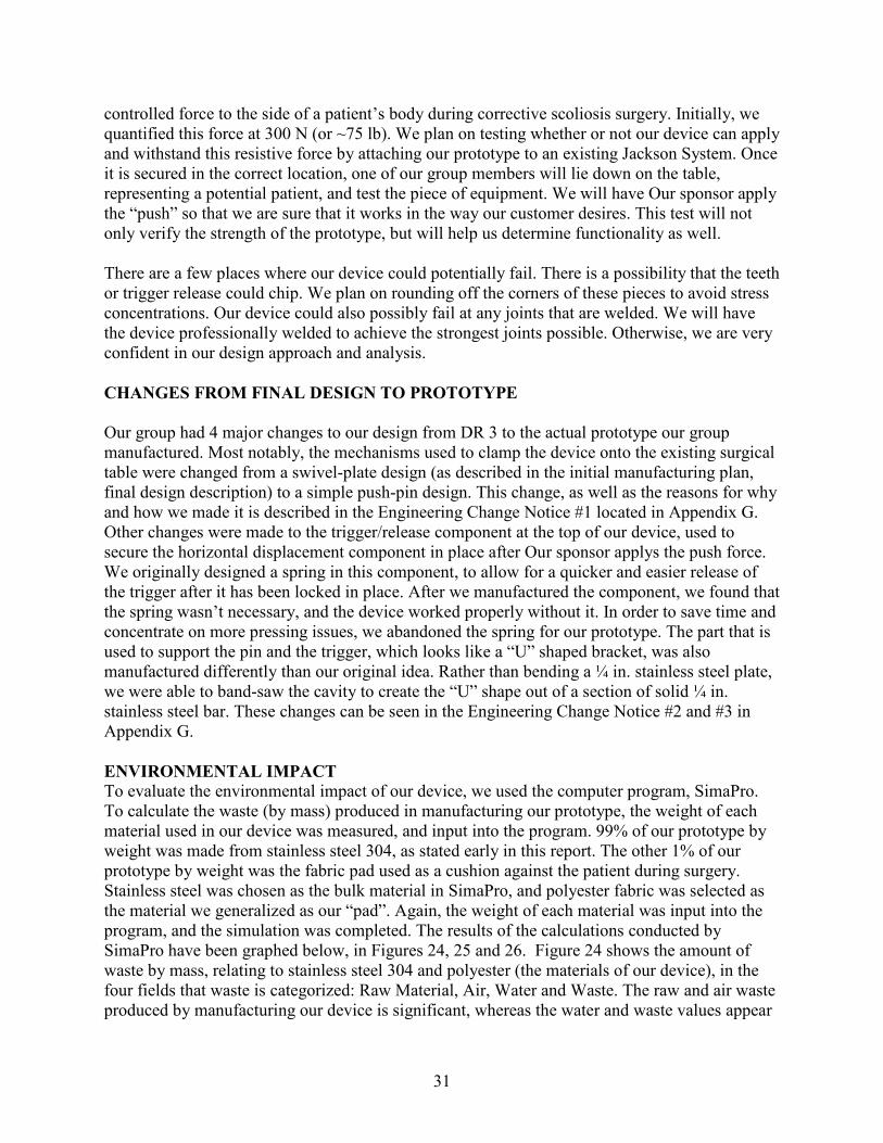
We also checked to make sure that the teeth would not bend when the trigger is about to release. We made some simplifications as shown in Figure 19, below. Assumptions include a point force of 300 N at the tip of the tooth from the trigger and assuming that the tooth can be represented as a beam of 1/8” width. This dimension is the average width of the tooth. Figure 19. Simplifications made for determining bending stress when trigger is about to release
from the teeth.
Using Eq. 3, we found the bending moment at the bottom of the tooth to be approximately 1.9 N-m and the maximum bending stress to be 178.6 MPa with a safety factor of 2.
IMy
B =σ Eq. 3
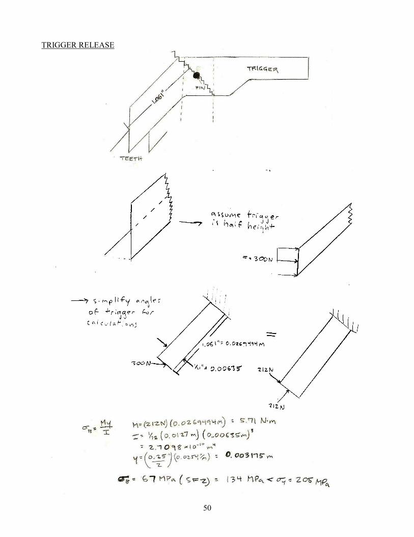
In this equation, σB is the bending stress in Pa, M is the bending moment in Newton-meters, and y is the distance from the centroid to the edge of the cross sectional area of the beam that represents the tooth. Trigger Release Mechanism Another key area of our design is the trigger release mechanism. This area is labeled “3” in Figure 16. Our biggest concerns are that the actual release will bend, the pin will tear out, or the pin bracket will shear off of the device. In order to test if the trigger release will bend, we assumed that the trigger was only half of its actual height. We did this because the force from the teeth are only applied to the bottom half of the trigger. If the trigger release does not fail with this assumption, it will not fail when it is full size. We also made some assumptions, shown in Figure 20, regarding the angles of the edges of the release. We did this to simplify calculations, however, they are minimal and will not affect the final prototype.

24
Figure 20. Various assumptions were made regarding the trigger release in order to simplify
calculations.
To solve for the bending stress at the curve of the release, we used Eq. 3, from above. In this instance, σB is the bending stress in Pa, M is the bending moment in Newton-meters, and y is the distance from the centroid to the edge of the cross sectional area of the trigger. We found the bending moment to be 5.71 N-m, and the bending stress to be 134 MPa with a safety factor of 2. In order to check if the pin holding the release will tear out, we used Eq. 4 [7].
mthF
=τ Eq. 4
In Eq. 4, τ is the tear-out stress, F is the applied force to the pin, t is the bracket thickness, h is the distance from the center of the pin to the edge of the bracket, and m is the number of shear planes. We found the tear-out stress for our pin to be 7.44 MPa with a safety factor of 2. A free body diagram can be seen in Figure 21. Figure 21. The tear out stress for the pin and bracket that holds the trigger release was calculated
using the free body diagram below.

25
The bracket that holds the pin for the trigger release will experience shear forces from the “push” force applied by the surgeon. This bracket will be welded onto the device using a fillet weld. Using Eq. 5 and a safety factor of 2, we found the shear stress on the weld to be ~4.0 MPa.
AV
=τ Eq. 5
In this equation, τ is the shear stress in Pa, V is the shear force in Newtons, and A is the area over which the force is being applied. In this case, the force is being applied over the area of the weld. We assumed a weld thickness of 1/8”. Vertical Height Control Weld The weld between the vertical height control of the device and the brackets that connect the device to the operating table is an area of very high concern in our design. This weld is labeled “4” in Figure . Using equations from Shigley’s Mechanical Engineering Design [8], we solved for the bending stress in the weld. These equations were rather complicated; see Appendix F for equations used and the complete calculations. With a safety factor of 2, and again assuming a weld thickness of 1/8”, we found the stress in the weld to be 106.4 MPa. Failure Mode and Effect Analysis (F.M.E.A.) After completing the above engineering analysis, our team performed a failure mode and effect analysis to confirm the problem areas of our final design. The F.M.E.A., seen in Appendix H, showed that we had examined the most crucial areas: the vertical height control weld, the trigger mechanism, and the horizontal translation bracket weld. MATERIAL SELECTION PROCESS [9] After collaborating with Our sponsor, we discovered radiolucency is not an issue. Our device will not interfere with the portion of the patient’s body Our sponsor is going to be viewing with the C-arm imaging device. Therefore, our team focused on finding a strong material with high corrosion resistance. In separate discussions with Professor Shih and Dan Johnson, we narrowed down our material selection to aluminum and stainless steel 316. Researching the two materials, and looking specifically at corrosion resistance, we found that aluminum could not withstand the sterilization process. This fact directed our team toward stainless steel 316, a very common material used in the operating room. When looking up possible components to order on McMaster-Carr’s website, we discovered that stainless steel 316 is extremely expensive, and has few variations in stock material dimensions. Keeping this information in mind, we looked at other stainless steel alloys and decided to use 304 to manufacture our prototype. Not only does stainless steel 304 have similar properties to 316, it is also less expensive with a wider variety of stock material available. To confirm our selection, we analyzed the key areas (these parts of our design and the analysis that goes with them is described above), and found that the largest stress our device would experience under its working conditions would be 200 MPa (with a safety factor of 2). This is the bending stress experienced by the trigger release. Using CES software that assists the material selection process for engineering projects, we placed limitations on price,

26
tensile strength, and durability characteristics. Price was a major constraint on evaluating potential materials. We therefore limited our price per kg. of material from $1.00 - $7.00, in the CES material selection computer program. We were in demand of a strong material that could withstand significant forces during surgery, so limits on yield strength and tensile strength were placed at 200 – 300 MPa, and 400 – 600 MPa, respectively. This limitation on strength filtered weak materials from our selection process, and displayed only those materials capable of handling the associated stresses with this device. We then narrowed the list of potential materials by applying constraints on durability, related to the material’s resistance to acids that will be used in the operating room to sterilize the material. By providing this information to the CES program, we were able to narrow down the 2800 materials available on CES to 61. Figure 22, is a screen shot of the materials the program told us would be appropriate for our prototype. Of these 61 possible materials, AISI stainless steel 304 was selected, again, due to availability reasons involved with purchasing the material. It is one of the cheaper stainless steel options (helping to keep our overall production costs down), and has the properties necessary to withstand the type of forces this device will encounter. More specifically, the material has a yield strength of 205 MPa (5 MPa greater than largest force applied during use) and is more than capable of resisting any sort of corrosion in the operating room.

27
Figure 22. CES confirmation of stainless steel AISI 304 material selection
For the pad that directly interacts with the patient’s body, we chose to use materials that would replicate the materials currently used in the pads on the Jackson table to support the body’s weight. The pad will be composed of a layer of 1” thick Minicel foam along with two layers of 1” thick polyfoam. We will then wrap the pad with a vinyl covering. In the operating room, a sterile covering will be placed around the entire pad. After research, we found that our device will most likely be welded using a low 300 series stainless steel, similar to the steel that we will be using for the rest of our device[11]. We plan on

28
having experts weld our device together and are confident that the welds will not fail. Even with a large safety factor, the stress in the welds are at most half of the yield strength of all of the low 300 series stainless steels. We plan on doing extensive testing of the device after it is welded to ensure that the welds are strong enough. If necessary, we will manufacture the hollow square tube vertical height control and the bracket that connects to the Jackson table as one piece, eliminating the low strength of the welded section. PROTOTYPE DESCRIPTION Our team will be manufacturing the final design in order to create a working prototype that Our sponsor will be able to use in the operating room. The goal of our project is to receive FDA approval on our device so that it can be used in the surgical field. With the manufacturing plan described in the following section, our group should have a working prototype that is ready for both the design expo and initial testing by December 4th. MANUFACTURING PLAN Methods of manufacturing included welding, band-sawing, drilling, and water-jet milling. This section describes the manufacturing steps we used in order to generate our prototype. The large density of stainless steel impacts the weight and mobility of the device we manufactured. In order to reduce on the impact of weight, we used hollow, extruded square tube stainless steel for a majority of the components. As shown in Figure 23 below, the components labeled 6, 8 and 9 were made of extruded hollow stainless steel square tubes bought stock from the manufacturer. Figure 23. Each manufactured part of the final design is labeled with a number for clarification.
1
2
3 6
4 5
7
8
9
100
111
12
131 14
1
15

29
The pieces of steel were cut using a band-saw, to the specified dimensions of our final design. In order to achieve vertical height variability to accompany different body shapes experienced in the operating room, we manufacturered a simple pin-hole design. Holes were drilled in parts 8 and 9 so that a pin can be inserted at various settings. The holes are 1” apart, and fit a 1/8” pin. Parts 8 and 9 were welded to parts 6 and 10, respectively. This weld will maintain strength throughout the device, and reduce on weight that could be gained potentially if the steel was screwed or bolted to the other components on the device. Solid stainless steel was used to build parts 11 and 12, the part that attaches the device to the current table. The parts were band-sawed manually in the ME 450 machine shop, to dimensions that have been specified. Tolerances with this method were difficult to reduce, and we have acknowledged this difficulty. Parts 10, 11 & 12 were then welded together, and function as the attachment mechanism to the frame of the Jackson Table currently used in the operating room. Part 10 was band-sawed from solid stainless steel. The latches, labeled parts 13 and 14 in Figure 23 were changed changed from a milled stainless steel plate design, to a simple pin and hole design similar to that of the vertical adjustment piece (8 and 9). The changes from this design to the prototype can be seen in ECN #2 and #3 in Appendix G. We decided to use solid stainless steel for Part 3, (the toothed beam of the device that will apply the force) because of its strength and durability characteristics, as well as for sterilization purposes. The teeth located on the top side of the 0.75” x 0.75” solid stainless steel bar, labeled part 3 on Figure 23, were manufactured using water-jet milling Water-jet milling uses a high-speed water jet with abrasive particles to cut materials.. A hole was drilled into both sides of part 3 for the handle and pad to be attached via a pin. The pad, labeled 1, was made of a combination of Minicel foam and polyfoam. This material was purchased online and cut down to our desired size using a band saw. The foam layers were glued together using a high strength epoxy. Once the epoxy had set, a cover was placed around the foam and stitched. The stichted pad was then glued to the stainless steel plate, labeled 2 in Figure 23. This stainless steel plate was welded to a small bracket, and attached to the toothed beam via a pin (as described in the previous paragraph). This pin and hole design allows for easy disassembly and cleaning of the pad. Our sponsor requested that a knob be attached and used for the component where he applies the push force to the patient. The knob is labeled 7 in Figure 23. We welded a small plate onto a hollow square tube. The plate was measured and cut to the size of an average human palm. Both of these parts were cut to size using a band saw. A hole was drilled in the square tubing so that it could be attached by a pin in the same way the pad is attached. A small lever-arm (trigger) acts as the securing component to the stainless steel beam and teeth used to translate the force from Our sponsor to the patient. Parts 4, 5, 6 and 15 make up this small mechanism. Part 4 was band-sawed, and drilled using stainless steel 304. It acts as the anchor for the stainless steel pin, part 15. Part 4 was then welded to part 6. The pin, part 15,

30
supports the thumb release, part 5. The thumb release was made by band-sawing a ¼ in. steel plate to the specified dimensions of our final design. Table 3. Material and manufacturing choice for each part of our design.
Part Number Material Associated Manufacturing Process 1 Foam Band-sawing 2 Stainless steel plate/square tube Drilling, band-sawing, welding 3 Solid stainless steel Water-jet milling, band-sawing,
drilling 4 Stainless steel plate Drilling, milling 5 Stainless steel plate Band-sawing, bending 6 Stainless steel square tube Band-sawing, welding 7 Stainless Steel plate/square tube Band-sawing, drilling, welding 8 Stainless steel square tube Band-sawing, drilling, welding 9 Stainless steel square tube Band-sawing, drilling, welding
10 Solid stainless steel Band-sawing, welding 11 Solid stainless steel Drilling, welding 12 Solid stainless steel Drilling, welding 13 Solid stainless steel Drilling, 14 Solid stainless steel Drilling 15 Solid stainless steel Assembly
Manufacturability was considered throughout the entire design process. It has been our goal since the beginning of this project to manufacture a working prototype, and possibly generate another design product after we evaluate the prototype’s functionality. Even so, we had to re-design several components due to manufacturing limitations. Despite our changes, the product that we designed serves the same purpose as before the re-design and reduces time spent on assembly. We believe these re-design components will facilitate more efficient assembly and reduce manufacturing time/cost. With that said, there are still issues that we believe need to be dealt with once manufacturing begins. The EDM process proved to be the best option for machining the teeth in part 3, however, we are un-sure about the results associated with this machining process. If the EDM method cannot create rigid-teeth within small tolerances, we will have to use another form of manufacturing, possibly the water-jet cutting process, or a simple band-saw approach. Another area of manufacturing that we are concerned with is the bracket that is used to hold the pin, for the release of the force application beam. This part is labeled part 5, and currently we plan on bending a plate of stainless steel, and drilling two concentric holes to create the fastener hole for the pin. Bending stainless steel is an inaccurate method of manufacturing, and is a potential manufacturing problem that we are evaluating and planning for. We also plan on eliminating sharp edges in the “teeth” of the device by filing down the edges material. Sharp edges will cause stress concentrations and could lead to failure. VALIDATION APPROACH Our group has designed a fully functional prototype that should meet all of our engineering specifications. The engineering problem that our device will solve is the application of a
31
controlled force to the side of a patient’s body during corrective scoliosis surgery. Initially, we quantified this force at 300 N (or ~75 lb). We plan on testing whether or not our device can apply and withstand this resistive force by attaching our prototype to an existing Jackson System. Once it is secured in the correct location, one of our group members will lie down on the table, representing a potential patient, and test the piece of equipment. We will have Our sponsor apply the “push” so that we are sure that it works in the way our customer desires. This test will not only verify the strength of the prototype, but will help us determine functionality as well. There are a few places where our device could potentially fail. There is a possibility that the teeth or trigger release could chip. We plan on rounding off the corners of these pieces to avoid stress concentrations. Our device could also possibly fail at any joints that are welded. We will have the device professionally welded to achieve the strongest joints possible. Otherwise, we are very confident in our design approach and analysis. CHANGES FROM FINAL DESIGN TO PROTOTYPE Our group had 4 major changes to our design from DR 3 to the actual prototype our group manufactured. Most notably, the mechanisms used to clamp the device onto the existing surgical table were changed from a swivel-plate design (as described in the initial manufacturing plan, final design description) to a simple push-pin design. This change, as well as the reasons for why and how we made it is described in the Engineering Change Notice #1 located in Appendix G. Other changes were made to the trigger/release component at the top of our device, used to secure the horizontal displacement component in place after Our sponsor applys the push force. We originally designed a spring in this component, to allow for a quicker and easier release of the trigger after it has been locked in place. After we manufactured the component, we found that the spring wasn’t necessary, and the device worked properly without it. In order to save time and concentrate on more pressing issues, we abandoned the spring for our prototype. The part that is used to support the pin and the trigger, which looks like a “U” shaped bracket, was also manufactured differently than our original idea. Rather than bending a ¼ in. stainless steel plate, we were able to band-saw the cavity to create the “U” shape out of a section of solid ¼ in. stainless steel bar. These changes can be seen in the Engineering Change Notice #2 and #3 in Appendix G. ENVIRONMENTAL IMPACT To evaluate the environmental impact of our device, we used the computer program, SimaPro. To calculate the waste (by mass) produced in manufacturing our prototype, the weight of each material used in our device was measured, and input into the program. 99% of our prototype by weight was made from stainless steel 304, as stated early in this report. The other 1% of our prototype by weight was the fabric pad used as a cushion against the patient during surgery. Stainless steel was chosen as the bulk material in SimaPro, and polyester fabric was selected as the material we generalized as our “pad”. Again, the weight of each material was input into the program, and the simulation was completed. The results of the calculations conducted by SimaPro have been graphed below, in Figures 24, 25 and 26. Figure 24 shows the amount of waste by mass, relating to stainless steel 304 and polyester (the materials of our device), in the four fields that waste is categorized: Raw Material, Air, Water and Waste. The raw and air waste produced by manufacturing our device is significant, whereas the water and waste values appear
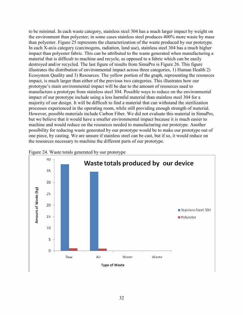
32
to be minimal. In each waste category, stainless steel 304 has a much larger impact by weight on the environment than polyester; in some cases stainless steel produces 400% more waste by mass than polyester. Figure 25 represents the characterization of the waste produced by our prototype. In each X-axis category (carcinogens, radiation, land use), stainless steel 304 has a much higher impact than polyester fabric. This can be attributed to the waste generated when manufacturing a material that is difficult to machine and recycle, as opposed to a fabric which can be easily destroyed and/or recycled. The last figure of results from SimaPro is Figure 26. This figure illustrates the distribution of environmental impact across three categories, 1) Human Health 2) Ecosystem Quality and 3) Resources. The yellow portion of the graph, representing the resources impact, is much larger than either of the previous two categories. This illustrates how our prototype’s main environmental impact will be due to the amount of resources used to manufacture a prototype from stainless steel 304. Possible ways to reduce on the environmental impact of our prototype include using a less harmful material than stainless steel 304 for a majority of our design. It will be difficult to find a material that can withstand the sterilization processes experienced in the operating room, while still providing enough strength of material. However, possible materials include Carbon Fiber. We did not evaluate this material in SimaPro, but we believe that it would have a smaller environmental impact because it is much easier to machine and would reduce on the resources needed to manufacturing our prototype. Another possibility for reducing waste generated by our prototype would be to make our prototype out of one piece, by casting. We are unsure if stainless steel can be cast, but if so, it would reduce on the resources necessary to machine the different parts of our prototype. Figure 24. Waste totals generated by our prototype

33
Figure 25. Characterization of waste products
Figure 26. Distribution of environmental impact of our prototype

34
TESTING AND VALIDATION To validate that our prototype was functional, we attached the device to a Jackson Spinal Surgery Table at the University of Michigan Hospital. A teammate laid on the table in the same fashion as a patient undergoing scoliosis correcting surgery would. We applied a force (~300 N), as the doctor would in surgery, and left the “patient” in the operating position for 15 minutes. The device applied the force successfully and did not cause any noticeable tissue damage on the “patient”. All components of our prototype fit perfectly and were completely compatible with the existing table and pads. Pictures of our validation testing can be seen in Figure 27. Figure 27. Testing of our prototype was completed at the University of Michigan Hospital using
a team member acting as “patient”.
We also performed a strength test by clamping the mechanism with a vice and applying ~650 N (team member’s body weight) to horizontal beam. The device works beyond our desired specifications and we are confident that it will not fail under any foreseeable circumstances.
DISCUSSION The finished prototype was a great success. The greatest strengths of our device include the ability for the surgeon to feel the amount of force he/she is applying to the patient, being able to attach the mechanism directly to the frame of the Jackson spinal surgery table, and the ability to be used on patients of different sizes with its vertical and horizontal adjustability. However, as good as our device turned out, it still has a few weaknesses. First, our mechanism is very heavy. Although weight is not a major concern, having a lighter prototype would make the operation of our device much easier on the surgical staff. If our team were to rebuild the prototype, we would either manufacture the bottom bracket (#1 in Figure 28 below) out of hollow square tubing, or change our material to carbon-fiber. These alternatives would drop the weight and make the device easier to handle. The pad is also a weakness of our mechanism. In an ideal situation, we would have created this piece using the same materials as the current Jackson spinal surgery table pads. The attachments that are being used in the operating room today are made of three layers of TEMPUR-Med memory foam, wrapped in a material known as Shear-Guard, both of

35
which are no longer produced. Having a pad made of these materials would make our device OR ready without the need of a sterile silicon sleeve as our current device requires. Another major weakness of our design has to do with the tolerances involved with the toothed bar and support (#2 in Figure 28). The tolerances of the toothed bar we had designed were thrown off due to the water-jet cutting process. These large tolerances made our mechanism slide in a way that we were unhappy with. Having professionals manufacture this part of our design would have made our device work much smoother. The last weak point of our design deals with the contact point between the teeth and the trigger. When pressure is put on the device, releasing the trigger sometimes becomes difficult. To solve this problem, we would have made the teeth shorter, and rounded the face of the trigger. Figure 28. Sections of weakness in prototype
In light of our shortcomings, there are steps that could be taken to make the device OR-ready. First, the aforementioned mechanical issues must be addressed, most notably finding an acceptable pad and pad covering. This is the only pervasive issue, as it would be mandatory for the pad to be made of acceptable medical material in order to be used in the OR. The next step, which our group is already investigating, is applying for a U.S. patent. A patent is necessary to protect what we are convinced is an innovative and promising idea, and will allow us to consult outside parties without fear of our design being stolen. Lastly, and most importantly, the device must be submitted to the FDA for testing before it can be used in the operating room. Such testing is required for all surgical devices, and Our sponsor could not use our device until it passes. One other issue that could be investigated is the environmental impact of using stainless steel. Because stainless steel requires an extensive amount of refinement, its production is resource intensive. Therefore, future investigation of other materials would be wise. Materials such as carbon fiber would be realistic substitutes for steel and would be less harmful to the environment, but might not be practical for all components of the device.
2
1
36
CONCLUSIONS The future of scoliosis surgery will be a minimally invasive technique that reduces patient bleeding, scarring, and post-operative recovery time. In order to perform this surgery, it is necessary for a force to be applied to the patient to straighten the spine during operation. The current tables used for spinal surgery, the Jackson system and the Allen system, do not have the capability to apply this force. We have evaluated the customer’s needs, converted them into engineering specifications, and have selected a concept as our final design. This concept exhibited the most effective and innovative components for the force transfer from the surgeon to the patient. The final design will allow the surgeon to feel the resistance of the force he is applying to the patient, enabling him to generate an accurate and controlled force to the patient’s side and lock the spine in a straightened position. The design we have generated will allow Our sponsor to complete his surgeries more successfully and efficiently. The prototype we manufactured over the course of this semester passes all engineering specifications and testing procedures. If used correctly in the operating room, the minimally invasive scoliosis surgery force application device will help to usher in a new era of patient friendly procedures.

37
REFERENCES [1] Scoliosis Blog, Spine with scoliosis, Retrieved 9/26, 2008 from http://hashealwaysbeenlikethat.blogspot.com/2008/02/sigh.html
[2] Mizuho OSI. OSI Products - Jackson Spinal Table. Retrieved 9/29, 2008, from http://www.mizuhosi.com/jacksonSpine.cfm
[3] Allen Medical Systems. Allen FLEX FRAME Spinal System. Retrieved 9/29, 2008, from http://www.allenmedical.com/pdf/01_Spine_US.pdf
[4] Allen Medical Systems. (2007). Allen Spinal System. Retrieved 9/29, 2008, from http://www.allenmedical.com/Spine/Spine_Brochure_D-770314-A2.pdf
[5] “Material Properties of Human Rib Corticol Bone from Dynamic Tension Coupon Testing,” Kemper AR, McNally C, Kennedy EA, Manoogian SJ, Rath AL, Ng TP, Stitzel JD, Smith EP, Duma SM, Masuoka F, Center for Injury Biomechanics , Blacksburg, VA.
[6] “in vitro Model System to Study the Damaging Effects of Prolonged Mechanical Loading of the Epidermis”, D. Bronneberg, C. V. C. Bouten, C. W. J. Oomens, P. M. Van Kemenade, and F. P. T. Baaijens, Department of Biomedical Engineering, Eindhoven University of Technology.
[7] “Joining of Materials and Structures”, R.M. Messler, pp. 68-69. 2004.
[8] Shigley, Joseph, Charles Mischke, and Richard Budynas. Mechanical Engineering Design. New York: McGraw-Hill Science, Engineering & Mathematics, 2003
[9] ASM Metals Reference Book, p.193: American Society for Metals: Metals Park, Ohio, 1981.
[10] Tempur-pedic Medical. Retrieved 11/2, 2008, from http://www.tempurmed.com/index.php/products/healthcare_index/C11/
[11] Phone conversation with Airway Welding on 11/3
[12] University of Michigan, Department of Neurosurgery

38
TEAM BIOGRAPHIES
Alex Was
My name is Alex Was, and I’m currently enrolled as a senior in the Department of Mechanical Engineering. I was born and raised in Ann Arbor, Michigan, and have lived here my entire life. I lived briefly in Dusseldorf, Germany when I was only two and a half years old. At the time my father was on sabbatical at a major university in Germany. Unfortunately it was so long ago that I don’t remember which school he worked with, or anything from the trip. My major interest in mechanical engineering comes from my hands-on attitude towards solving problems. Ever since I was little, I couldn’t stop taking things apart and putting them back together, figuring out how each component in my toy cars or my bike worked. Mechanical engineering seemed like the broadest form of engineering, which I thought would allow me to pursue most any career I wish when I graduate in April, 2009. My plans as of now are to graduate on time in 2009, possibly work in a consulting firm for 2-5 years, and then apply to business school after gaining experience in the engineering industry. An interesting fact that many of my close friends know about me and one that can either help or hurt me in my future is that I am severely colorblind. I have trouble identifying and distinguishing between almost ever pair of like- colors (yellow/green, red/brown, blue/purple, and so on). I am also very interested in the bio-mechanics industry, whether that is the hospital, or a firm that specializes in designing and producing bio-medical equipment. I’m taking a tissue mechanics class along with this project, so my semester is practically split down the middle between mechanical and biomedical engineering work. Jeffrey Issner
I am currently a senior studying Mechanical Engineering at the University of Michigan. I was raised in West Bloomfield, Michigan, and some would say I was born to be an engineer. My father and my brother both work in the auto industry. That being said, I was always taught to do things “the engineering way”. I’ve always had a strong desire to learn about how things work and how they can be improved to make people’s lives better. As I entered high school, I strongly believed that I would become a doctor. After spending my senior year in a medical mentorship program following an urologist, I quickly learned that I absolutely did not want to be a practicing doctor. I found that I would rather find solutions to problems rather than just diagnose the problems.

39
My father encouraged me to pursue an engineering degree and I have not looked back. I have found a nice mixture between my desire to be a doctor and my desire to be an engineer in the form of biomedical engineering. I have focused many of my projects during my time at U of M on the medical field, including an extracorporeal lung, a device to close up the chest after open chest surgery, and finally this project. Besides my education, some of my interests include skiing, music, and Michigan football. I have been an avid skier since the age of three and there is nowhere I would rather be than on top of a mountain. After this year, I plan on pursuing a career in the biomedical field. Kyle Cryderman
I was born and raised in Lansing, Michigan. I attended Holt High School where I ran cross country and played basketball. My favorite subjects in school were always math and science, and my Grandfather (a Civil Engineer from MSU) always told me I had the mind of an engineer, thus I began searching for a good engineering school. I visited both Purdue University and the University of Michigan, and decided UM felt more like home (despite growing up a die-hard Spartan fan). Going in to my freshman year here at the college of engineering, I knew that I wanted to aspire for a
career in either the biomedical or automotive industries. This led me directly to mechanical engineering. I knew that with a degree in ME, because of its versatility, I could go either way after graduation. My dream is to have a career designing medical products or automobile components. I am well aware that these two fields are on opposite sides of the spectrum, but both have always caught my interest. For the most part, that sums up the education side of my life, I also enjoy running, playing golf, playing basketball and being with my friends and family. Mike Tanis Before August of 2005, when I arrived in Ann Arbor for school, I hadn’t the slightest idea what city life was. And while Ann Arbor is still somewhat small-town, it dwarfs my hometown of Imlay City, MI. The Big IC, as it’s affectionately called around my high school, was the last glimmer of civilization as big city folk would travel up Van Dyke highway into the thumb, and my dad has owned a farm there for 45 years. Imlay is a quaint little farm town and provided a wholesome place to grow up, but provided little entertainment away from home and, as a result, I learned to entertain myself by

40
tinkering with the cars, trucks, tractors, motorcycles and lawnmowers that littered the storage barns of our farm. I quickly grew to love mechanical work, and had quite the opposite attraction to farm work, which seemed tedious and boring. I remember telling my father one day in the field, “I’d rather design a machine to pull the weeds than do it myself.” Though I rarely entertain the idea of entering the agricultural products industry, I still hold a passion for innovative machines and have worked hard over the past four years so that I may one day deal with such dreams on a daily basis. Upon graduation in the spring, I plan to search out a position that will allow me to actively utilize my desire to design, be it in the automotive, power-sports or medical industry.

41
APPENDIX A

42
APPENDIX B

43
APPENDIX C
Concept 1 Concept 2
Concept 3 Concept 4

44
Concept 5

45
APPENDIX D
Locking/release mechanism
Locking/release mechanism
Surgeon force
Force on patient

46
Attachment to Jackson table
Vertical adjustment
Vertical adjustment
Attachment to Jackson table

47
APPENDIX E

48
APPENDIX F
FORCE ON TEETH (LOCKED)
TRIGGER AT TOP OF TEETH (ON RELEASE)
49
PAD PRESSURE ON SKIN
PIN TEAR OUT FORCE
50
TRIGGER RELEASE

51
A
VIEW A (WELD OUTLINE)
[8]
CLAMP TO VERTICAL HEIGHT ADJUSTMENT WELD
TRIGGER BRACKET WELD
VIEW B (WELD OUTLINE) B

52
APPENDIX G
Engineering Change Notice #1, Clamp
Notes: Needed to replace ¼ in. steel plates with ¼ in. removable pins for clamping mechanism used to secure device on to existing Jackson table. Changes made because of time constraints and ease of manufacturing. Changes made 11/28/08. Authorized by Dan Johnson.
1/4 “ steel plate bolted to brackets for clamping mechanism 1/4 “ pins inserted into
drilled holes for clamping mechanism
WAS: IS:
Engineering Change Notices #2 and #3, Trigger/Release for Horizontal Displacement Control
Notes: Originally we planned to use a spring to assist in the release of the trigger, but this was determined to be unnecessary. We also planned on bending stainless steel to produce the support for the pin/trigger, but we were able to band-saw that cavity out of a section of solid stainless steel bar. Changes made 11/20/08. Authorized by Dan Johnson.
Bent stainless steel
Spring located here to assist in release of the trigger
WAS: IS:
Band-sawed stainless steel
Spring was unnecessary, device fully functional without spring

53
Engineering Change Notice #6, Diagonal Support Beam
Notes: The diagonal support was installed on the prototype to allow for easy translation of the horizontal displacement beam. We didn’t realize that there would be an issue prior to manufacturing. However, due to tolerance issues caused by water jet cutting, we solved this problem using the diagonal support beam. Approved by Dan Johnson. Changes made 12/2/08.
WAS: IS:
Engineering Change Notices 4 & 5, Pad Securement & Pad Design
Notes: Two changes were made to the pad design/manufacturing. The pad was glued to a the ¼ in. stainless steel plate rather than being bolted to save time, and to reduce on potential weight from nuts & bolts. We also made a square-face on the pad to maximize the contact area between patient and pad, to distribute the applied pressure. Changes approved by Dan Johnson and Team 13. Changes made 11/19/08.
WAS: IS:
Pad was to be bolted onto stainless steel plate
Pad contoured to fit patient’s side
Pad glued to stainless steel plate
Square-faced pad to maximize contact area between patient and pad
Diagonal beam added to support horizontal displacement beam

54
APPENDIX H


![Minimally invasive non-surgical vs. surgical approach for ...dictable [12]. More recently, minimally invasive surgical therapy (MIST), modified minimally invasive surgical therapy](https://img.pdfslide.us/doc/110x75/5eddda76ad6a402d6669115c/minimally-invasive-non-surgical-vs-surgical-approach-for-dictable-12-more.jpg)