Embed Size (px)
Citation preview
1© KEMET Electronics Corporation • P.O. Box 5928 • Greenville, SC 29606 • 864-963-6300 • www.kemet.com R7005_UC2_UD2 • 8/8/2017One world. One KEMET
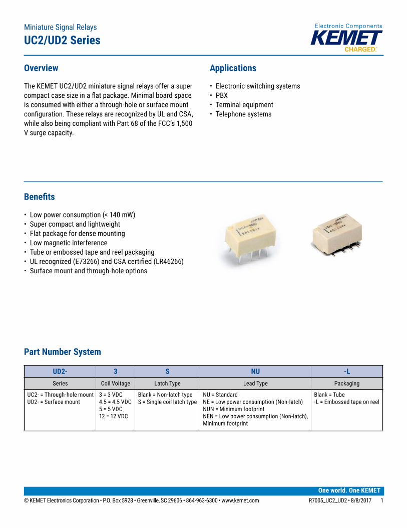
Benefits
• Low power consumption (< 140 mW)• Super compact and lightweight• Flat package for dense mounting• Low magnetic interference• Tube or embossed tape and reel packaging• ULrecognized(E73266)andCSAcertified(LR46266)• Surface mount and through-hole options
Overview
The KEMET UC2/UD2 miniature signal relays offer a super compactcasesizeinaflatpackage.Minimalboardspaceis consumed with either a through-hole or surface mount configuration.TheserelaysarerecognizedbyULandCSA,while also being compliant with Part 68 of the FCC’s 1,500 V surge capacity.
Applications
• Electronic switching systems• PBX• Terminal equipment• Telephone systems
Miniature Signal Relays
UC2/UD2 Series
Part Number System
UD2- 3 S NU -LSeries Coil Voltage Latch Type Lead Type Packaging
UC2- = Through-hole mount UD2- = Surface mount
3 = 3 VDC4.5 = 4.5 VDC5 = 5 VDC12 = 12 VDC
Blank = Non-latch typeS = Single coil latch type
NU = StandardNE = Low power consumption (Non-latch)NUN = Minimum footprint NEN = Low power consumption (Non-latch), Minimum footprint
Blank = Tube-L = Embossed tape on reel

2© KEMET Electronics Corporation • P.O. Box 5928 • Greenville, SC 29606 • 864-963-6300 • www.kemet.com R7005_UC2_UD2 • 8/8/2017
Miniature Signal Relays – UC2/UD2 Series
Dimensions – Millimeters
UC2 Series
B Maximum
P2
P3
0.2
D Maximum
H Maximum0.4
P1P13.21.5 1.5
D Maximum
H Maximum
K0.4
P1P13.21.5 1.5
0.2
P2
B Maximum
K
UD2 Series
B Maximum
P2
P3
0.2
D Maximum
H Maximum0.4
P1P13.21.5 1.5
D Maximum
H Maximum
K0.4
P1P13.21.5 1.5
0.2
P2
B Maximum
K
Series D H B P1 P2 P3 KUC2 (NU, NE) 10.6 5.3 6.5 2.2 5.08 — 3.4UD2 (NU, NE) 10.6 5.45 6.5 2.2 5.08 8.4 0.2
UD2 (NUN, NEN) 10.6 6.0 6.5 2.2 5.08 6.8 0.2
General tolerance: ±0.3Tolerance of lead pitch: ±0.15
3© KEMET Electronics Corporation • P.O. Box 5928 • Greenville, SC 29606 • 864-963-6300 • www.kemet.com R7005_UC2_UD2 • 8/8/2017
Miniature Signal Relays – UC2/UD2 Series
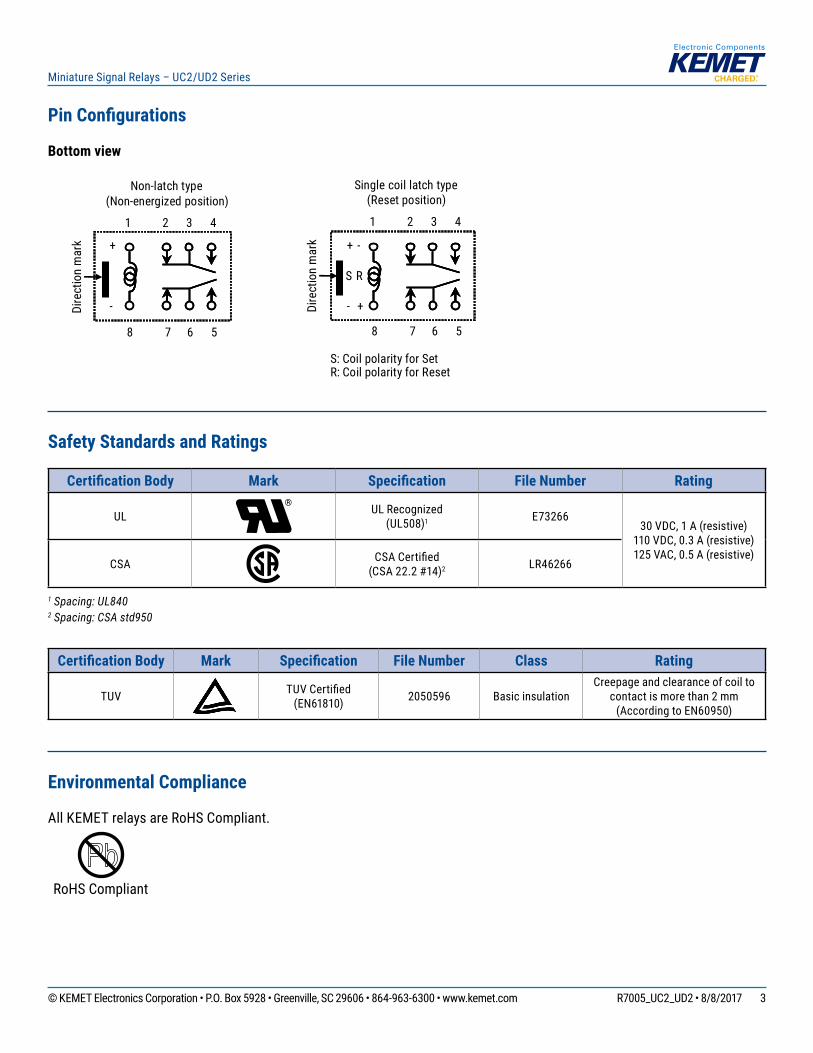
Pin Configurations
Bottom view
-
+
+
-
RS
+
-
S: Coil polarity for SetR: Coil polarity for Reset
1 2 3 4
8 7 6 5
Single coil latch type(Reset position)
Non-latch type(Non-energized position)
1 2 3 4
8 7 6 5
Dire
ctio
n m
ark
Dire
ctio
n m
ark
Safety Standards and Ratings
Certification Body Mark Specification File Number Rating
UL UL Recognized(UL508)1 E73266
30 VDC, 1 A (resistive)110 VDC, 0.3 A (resistive)125 VAC, 0.5 A (resistive)
CSA CSACertified(CSA 22.2 #14)2 LR46266
1 Spacing: UL840 2 Spacing: CSA std950
Certification Body Mark Specification File Number Class Rating
TUV TUVCertified(EN61810) 2050596 Basic insulation
Creepage and clearance of coil to contact is more than 2 mm
(According to EN60950)
Environmental Compliance
All KEMET relays are RoHS Compliant.
RoHS Compliant
4© KEMET Electronics Corporation • P.O. Box 5928 • Greenville, SC 29606 • 864-963-6300 • www.kemet.com R7005_UC2_UD2 • 8/8/2017
Miniature Signal Relays – UC2/UD2 Series
Table 1 – Ratings & Part Number Reference
Part Number Nominal Coil Voltage (VDC) Lead Type Packaging
UC2-3(1)NU 3 Radial TubeUC2-4.5(1)NU 4.5 Radial TubeUC2-5(1)NU 5 Radial TubeUC2-12(1)NU 12 Radial Tube
UC2-3NE1 3 Radial, Low power consumption TubeUC2-4.5NE1 4.5 Radial, Low power consumption TubeUC2-5NE1 5 Radial, Low power consumption Tube
UD2-3(1)NU 3 Surface mount TubeUD2-4.5(1)NU 4.5 Surface mount TubeUD2-5(1)NU 5 Surface mount TubeUD2-12(1)NU 12 Surface mount Tube
UD2-3NE1 3 Surface mount, Low power consumption TubeUD2-4.5NE1 4.5 Surface mount, Low power consumption TubeUD2-5NE1 5 Surface mount, Low power consumption Tube
UD2-3(1)NU-L 3 Surface mount Tape on ReelUD2-4.5(1)NU-L 4.5 Surface mount Tape on ReelUD2-5(1)NU-L 5 Surface mount Tape on ReelUD2-12(1)NU-L 12 Surface mount Tape on Reel
UD2-3NE-L1 3 Surface mount, Low power consumption Tape on ReelUD2-4.5NE-L1 4.5 Surface mount, Low power consumption Tape on ReelUD2-5NE-L1 5 Surface mount, Low power consumption Tape on Reel
UD2-3(1)NUN 3 Surface mount, Minimum footprint TubeUD2-4.5(1)NUN 4.5 Surface mount, Minimum footprint TubeUD2-5(1)NUN 5 Surface mount, Minimum footprint TubeUD2-12(1)NUN 12 Surface mount, Minimum footprint Tube
UD2-3NEN1 3 Surface mount, Low power consumption, Minimum Footprint TubeUD2-4.5NEN1 4.5 Surface mount, Low power consumption, Minimum Footprint TubeUD2-5NEN1 5 Surface mount, Low power consumption, Minimum Footprint Tube
UD2-3(1)NUN-L 3 Surface mount, Minimum footprint Tape on ReelUD2-4.5(1)NUN-L 4.5 Surface mount, Minimum footprint Tape on ReelUD2-5(1)NUN-L 5 Surface mount, Minimum footprint Tape on ReelUD2-12(1)NUN-L 12 Surface mount, Minimum footprint Tape on Reel
UD2-3NEN-L1 3 Surface mount, Low power consumption, Minimum Footprint Tape on ReelUD2-4.5NEN-L1 4.5 Surface mount, Low power consumption, Minimum Footprint Tape on ReelUD2-5NEN-L1 5 Surface mount, Low power consumption, Minimum Footprint Tape on Reel
(1) To complete KEMET part number, leave blank for Non-latch or insert S for Single coil. Designates latch type. 1 Only available as Non-latch.
5© KEMET Electronics Corporation • P.O. Box 5928 • Greenville, SC 29606 • 864-963-6300 • www.kemet.com R7005_UC2_UD2 • 8/8/2017
Miniature Signal Relays – UC2/UD2 Series
Land Pattern – Millimeters
UC2 Series (bottom view)
V
0.8
X
1.5 1.53.2 2.2 2.2
7.6
8 - ø 0.851.51.5
3.2 2.2 2.27.6
V
UD2 Series (top view)
V
0.8
X
1.5 1.53.2 2.2 2.2
7.6
8 - ø 0.851.51.5
3.2 2.2 2.27.6
V
Series V XUC2 (NU, NE) 5.08 —UD2 (NU, NE) 6.74 1.86
UD2 (NUN, NEN) 5.94 2.66
6© KEMET Electronics Corporation • P.O. Box 5928 • Greenville, SC 29606 • 864-963-6300 • www.kemet.com R7005_UC2_UD2 • 8/8/2017
Miniature Signal Relays – UC2/UD2 Series
Soldering Process
UC2 – Through-hole MountingAutomatic Soldering Preheating: 110–120°C/110 seconds (maximum) Solder temperature: 260°C maximum Solder time: 5 seconds maximum
Note: KEMET recommends cooling down a printed circuit board to less than 110°C within 40 seconds after soldering.Manual Soldering Solder temperature: 350°C maximum Solder time: 3 seconds maximum
UD2 – Surface Mounting
Note:Temperatureprofileshowsprintedcircuitboardsurfacetemperatureontherelayterminalportion. PleaseconsultKEMETifyouwishtouseatemperatureprofileotherthanabove.
IRS Method
200
180
190 (Maximum 300)
45 (Maximum 70)
70 (Maximum 120)
220
200
180
Temperature(˚C)
220
Maximum 240˚C
Time (seconds)
7© KEMET Electronics Corporation • P.O. Box 5928 • Greenville, SC 29606 • 864-963-6300 • www.kemet.com R7005_UC2_UD2 • 8/8/2017
Miniature Signal Relays – UC2/UD2 Series
Contact Specifications
*1 This value is a reference value in the resistance load. Minimum capacity changes depending on the switching frequency, environment temperature, and load.
*2 Rise time: 10 µs; decay time to half crest: 160 µs.*3 Rise time: 2 µs; decay time to half crest: 10 µs.*4 This shows the number of operations with fatal defects. Stable characteristics are maintained for 1 x 10⁷ operations.
Coil Specifications
Non-latch Type (at 20°C)
Nominal Coil Voltage (VDC)
Coil Resistance (Ω) ±10%
Operating Voltage1 (VDC)
Release Voltage1 (VDC)
Nominal Operating Power (mW)
3 64.3 2.25 0.3 140
4.5 145 3.38 0.45 140
5 178 3.75 0.5 140
12 1028 9.0 1.2 140
1 Test by pulse voltage.
Item UC2/UD2Contact Form 2 Form C
Contact Material Silver alloy with gold alloy overlay
Contact Ratings
Maximum Switching Power 30 W, 37.5 VA
Maximum Switching Voltage 220 VDC, 250 VAC
Maximum Switching Current 1 A
Maximum Carrying Current 1 A
Minimum Contact Ratings 10 mVDC, 10 µA*1
Initial Contact Resistance 100mΩmaximum(initial)
Operating Time (excluding bounce) Approximately 2 milliseconds
Release Time (excluding bounce) Approximately 1 milliseconds
Insulation Resistance 1,000MΩat500VDC
Withstand Voltage
Between Open Contacts 1,000 VAC (for one minute), 1,500 V surge (10 x 160 µs)*2
Between Adjacent Contacts 1,000 VAC (for one minute), 1,500 V surge (10 x 160 µs)*2
Between Coil and Contacts 1,500 VAC (for one minute), 2,500 V surge (2 x 10 µs)*3
Shock Resistance 735 m/s2 (75 G) – misoperation980 m/s2 (100 G) – destructive failure
Vibration Resistance 10 to 55 Hz, double amplitude 3 mm (20 G) – misoperation10 to 55 Hz, double amplitude 5 mm (30 G) – destructive failure
Ambient Temperature−40to+85°C
−40to+70°C(Lowpowerconsumptiontype)
Coil Temperature Rise 18°C at nominal coil voltage (140 mW)
RunningSpecificationsNon-load 5 x 10⁷ operations (Non-latch type)*4
1 x 10⁷ operations (Latch type)
Load 30 VDC 1 A (resistive), 1 x 10⁵ operations at 20°C, 1 Hz125 VAC 0.3 A (resistive), 1 x 10⁵ operations at 20°C, 1 Hz
Weight Approximately 0.8 g
8© KEMET Electronics Corporation • P.O. Box 5928 • Greenville, SC 29606 • 864-963-6300 • www.kemet.com R7005_UC2_UD2 • 8/8/2017
Miniature Signal Relays – UC2/UD2 Series
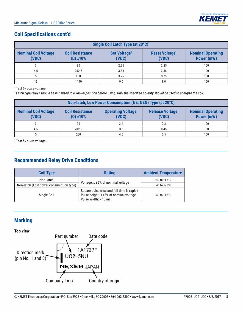
Coil Specifications cont’d
Single Coil Latch Type (at 20°C)2
Nominal Coil Voltage (VDC)
Coil Resistance (Ω) ±10%
Set Voltage1 (VDC)
Reset Voltage1 (VDC)
Nominal Operating Power (mW)
3 90 2.25 2.25 100
4.5 202.5 3.38 3.38 100
5 250 3.75 3.75 100
12 1440 9.0 9.0 100
1 Test by pulse voltage.2Latchtyperelaysshouldbeinitializedtoaknownpositionbeforeusing.Onlythespecifiedpolarityshouldbeusedtoenergizethecoil.
Non-latch, Low Power Consumption (NE, NEN) Type (at 20°C)
Nominal Coil Voltage (VDC)
Coil Resistance (Ω) ±10%
Operating Voltage1 (VDC)
Release Voltage1 (VDC)
Nominal Operating Power (mW)
3 90 2.4 0.3 100
4.5 202.5 3.6 0.45 100
5 250 4.0 0.5 100
1 Test by pulse voltage.
Recommended Relay Drive Conditions
Coil Type Rating Ambient TemperatureNon-latch
Voltage:≤±5%ofnominalvoltage−40to+85°C
Non-latch (Low power consumption type) −40to+70°C
Single CoilSquare pulse (rise and fall time is rapid)Pulseheight:≤±5%ofnominalvoltagePulse Width: > 10 ms
−40to+85°C
Marking
Top view
Country of origin
Part number
Company logo
Date code
Direction mark (pin No. 1 and 8) UC2-5NU
JAPAN
1A1727F
9© KEMET Electronics Corporation • P.O. Box 5928 • Greenville, SC 29606 • 864-963-6300 • www.kemet.com R7005_UC2_UD2 • 8/8/2017
Miniature Signal Relays – UC2/UD2 Series
Maximum Coil VoltageMaximum value of permissible alteration
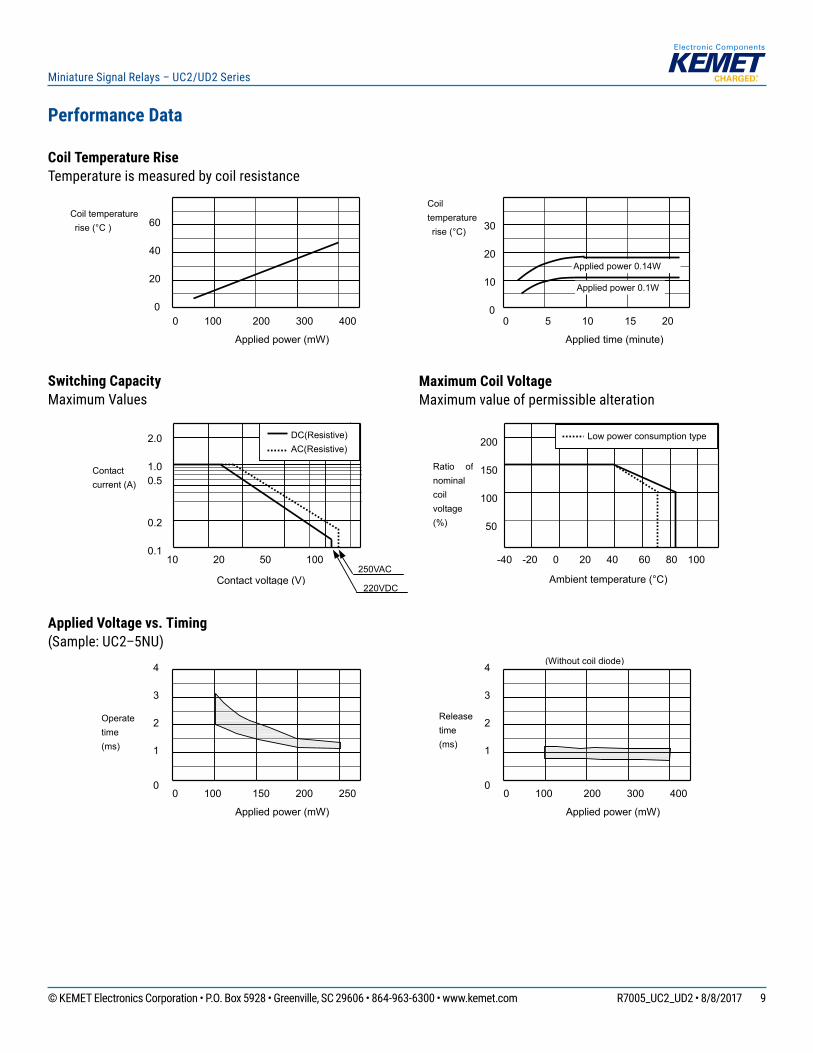
Performance Data
Coil Temperature RiseTemperature is measured by coil resistance
Switching CapacityMaximum Values
Applied Voltage vs. Timing(Sample: UC2–5NU)
All specifications in this catalog and production status of products are subject to change without notice. Prior to the purchase, please contact NEC TOKIN for updated product data. Please request for a specification sheet for detailed product data prior to the purchase. Before using the product in this catalog, please read "Precautions" and other safety precautions listed in the printed version catalog.
2007.08.03 P0894EMDD03VOL03E
UC2/UD2 SERIES
8
PERFORMANCE DATA
0 100 200 300 400
60 40 20 0
Applied power (mW)
0 5 10 15 20
30 20 10 0
Applied time (minute)
-40 -20 0 20 40 60 80 100
200 150 100 50
Ambient temperature (°C)
10 20 50 100
2.0 1.00.5 0.2 0.1
Contact voltage (V)
0 100 150 200 2500
Applied power (mW)
1
2
3
4
0 100 200 300 4000
Applied power (mW)
1
2
3
4
COIL TEMPERATURE RISE Temperature is measured by coil resistance
SWITCHING CAPACITY This is allowed maximum value. Inquire with NEC TOKIN for maximum value under continuous
MAXIMUM COIL VOLTAGE This is a maximum value of permissible alteration. Inquire with NEC TOKIN under continuous use.
APPLIED VOLTAGE VS. TIMING (Sample:UC2-5NU)
(Without coil diode)
DC(Resistive) AC(Resistive)
250VAC
220VDC
Applied power 0.1W
Applied power 0.14W
Coil temperature rise (°C )
Coil temperature rise (°C)
Contact current (A)
Ratio ofnominal coil voltage (%)
Operate time (ms)
Release time (ms)
Low power consumption type
10© KEMET Electronics Corporation • P.O. Box 5928 • Greenville, SC 29606 • 864-963-6300 • www.kemet.com R7005_UC2_UD2 • 8/8/2017
Miniature Signal Relays – UC2/UD2 Series
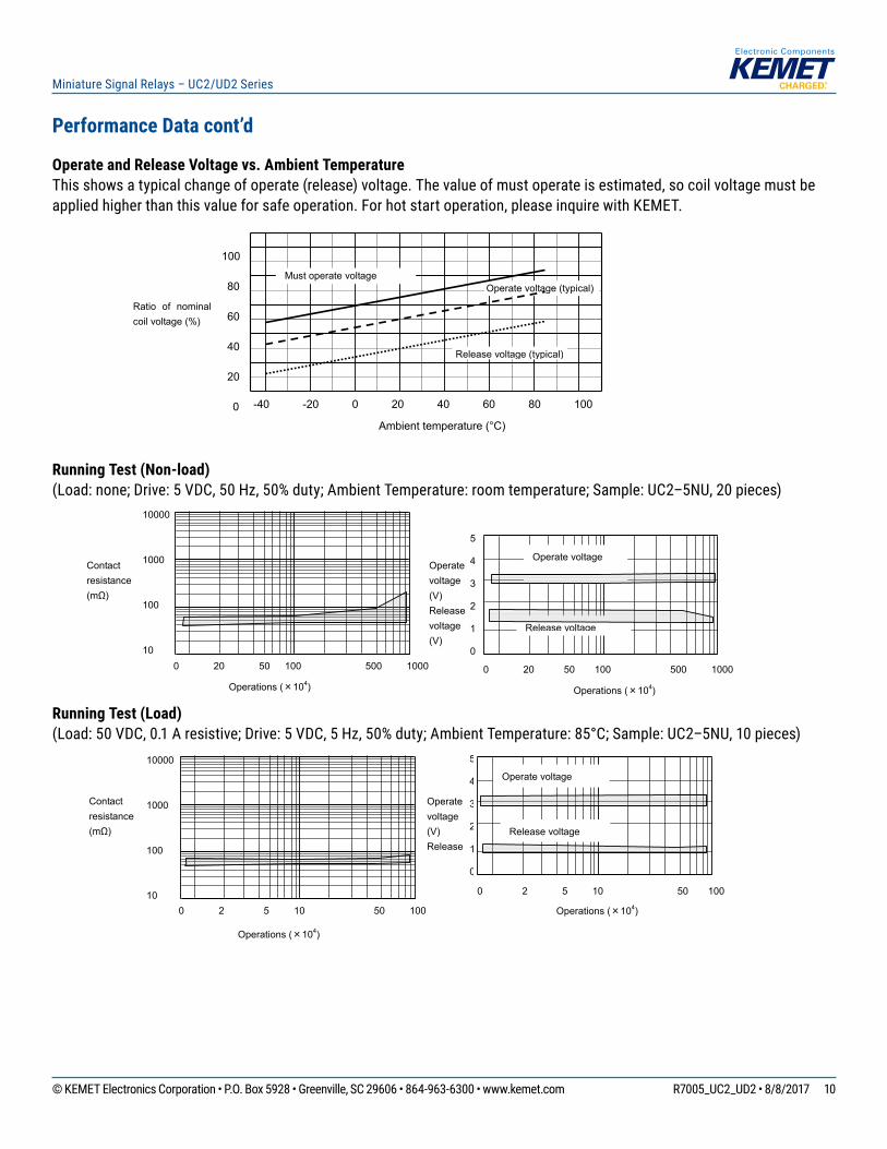
Performance Data cont’d
Operate and Release Voltage vs. Ambient TemperatureThis shows a typical change of operate (release) voltage. The value of must operate is estimated, so coil voltage must be applied higher than this value for safe operation. For hot start operation, please inquire with KEMET.
Running Test (Non-load)(Load:none;Drive:5VDC,50Hz,50%duty;AmbientTemperature:roomtemperature;Sample:UC2–5NU,20pieces)
Running Test (Load)(Load:50VDC,0.1Aresistive;Drive:5VDC,5Hz,50%duty;AmbientTemperature:85°C;Sample:UC2–5NU,10pieces)
All specifications in this catalog and production status of products are subject to change without notice. Prior to the purchase, please contact NEC TOKIN for updated product data. Please request for a specification sheet for detailed product data prior to the purchase. Before using the product in this catalog, please read "Precautions" and other safety precautions listed in the printed version catalog.
2007.08.03 P0894EMDD03VOL03E
UC2/UD2 SERIES
9
10000 1000 100 10
-40 -20 0 20 40 60 80 100
100 80 60 40 20 0
Ambient temperature (°C)
OPERATE AND RELEASE VOLTAGE VS.AMBIENT TEMPERATURE This shows a typical change of operate (release) voltage. The value of must operate is estimated, so coil voltage must be applied more than this value for safety operation. For hot start operation, please inquire with NEC TOKIN.
Must operate voltage Operate voltage (typical)
Release voltage (typical)
Ratio of nominal coil voltage (%)
Operations (×104)
RUNNING TEST (Non-load) (Load: none, Drive:5VDC,50Hz,50%duty, Ambient temperature :room temperature, Sample:UC2-5NU ,20pieces)
0 20 50 100 500 1000
10000 1000 100 10
Contact resistance (mΩ)
5
4
3
2
1
0
Operations (×104)
0 20 50 100 500 1000
Operate voltage
Release voltage
Operate voltage (V) Release voltage (V)
RUNNING TEST(Load) (Load: 50VDC 0.1A resistive,Drive:5VDC,5Hz,50%duty,Ambient temperature:85 °C, Sample:UC2-5NU ,10pieces)
Contact resistance (mΩ)
0 2 5 10 50 100
Operations (×104)
5
4
3
2
1
0
0 2 5 10 50 100
Operate voltage (V) Release
Operations (×104)
Operate voltage
Release voltage
11© KEMET Electronics Corporation • P.O. Box 5928 • Greenville, SC 29606 • 864-963-6300 • www.kemet.com R7005_UC2_UD2 • 8/8/2017
Miniature Signal Relays – UC2/UD2 Series
Performance Data cont’d
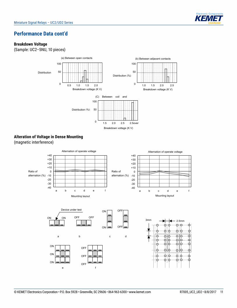
Breakdown Voltage(Sample: UC2–5NU, 10 pieces)
Alteration of Voltage in Dense Mounting(magnetic interference)
All specifications in this catalog and production status of products are subject to change without notice. Prior to the purchase, please contact NEC TOKIN for updated product data. Please request for a specification sheet for detailed product data prior to the purchase. Before using the product in this catalog, please read "Precautions" and other safety precautions listed in the printed version catalog.
2007.08.03 P0894EMDD03VOL03E
UC2/UD2 SERIES
10
100 50 0 0.5 1.0 1.5 2.0
Breakdown voltage (K V)
100 50 0 1.0 1.5 2.0 2.5
100 50 0 1.5 2.0 2.5 2.5over
BREAKDOWN VOLTAGE Sample: UC2-5NU 10peices
(a) Between open contacts (b) Between adjacent contacts
(C) Between coil and
ALTERNATION OF VOLTAGE IN DENSE MOUNTING (Magnetic interference)
Distribution Distribution (%)
Distribution (%)
Breakdown voltage (K V)
Breakdown voltage (K V)
ON ON OFF OFF
ON ON
OFF OFF
ON ON ON
OFF OFF OFF
e f
Device under test
a b c d
a b c d e f
+40+30+20+10 0 -10 -20 -30 -40
Mounting layout
Alternation of operate voltage
Ratio of alternation (%)
+40+30+20+10 0-10-20-30-40
Mounting layout
a b c d e f
Ratio of alternation (%)
Alternation of operate voltage
2.5mm 3mm
12© KEMET Electronics Corporation • P.O. Box 5928 • Greenville, SC 29606 • 864-963-6300 • www.kemet.com R7005_UC2_UD2 • 8/8/2017
Miniature Signal Relays – UC2/UD2 Series
APPEARANCE
1,200 pieces/Reel Reel diameter: 380mm
TAPE DIMENSIONS RELAY DIRECTION MARK AND TAPE CARRYING DIRECTION
Reel
Top cover tape
Emboss
Carrying tape
24.0
4Φ 1.5
Φ 2.2
16
11.5
2.0 1.75
12.1
0.4
max. 8.1
14.724.0
4Φ 1.5
Φ 2.2
12
11.5
2.0 1.75
B
0.4
A
11.4
Direction mark
Sprocket hole
Direction of unreeling
Direction mark
Sprocket hole
Direction of unreeling
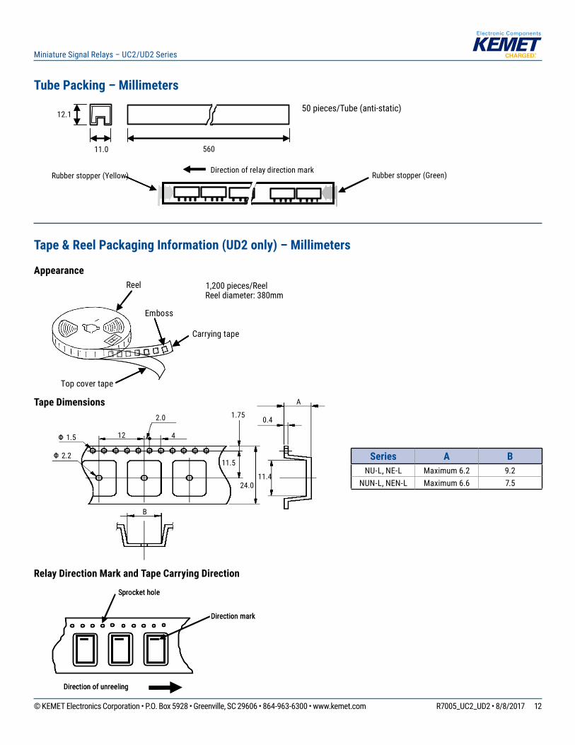
Tube Packing – Millimeters50 pieces/Tube (anti-static)
11.0
12.1
560
Direction of relay direction markRubber stopper (Yellow) Rubber stopper (Green)
Tape & Reel Packaging Information (UD2 only) – Millimeters
Appearance
Tape Dimensions
Relay Direction Mark and Tape Carrying Direction
Series A BNU-L, NE-L Maximum 6.2 9.2
NUN-L, NEN-L Maximum 6.6 7.5
13© KEMET Electronics Corporation • P.O. Box 5928 • Greenville, SC 29606 • 864-963-6300 • www.kemet.com R7005_UC2_UD2 • 8/8/2017
Miniature Signal Relays – UC2/UD2 Series
Notes on Using Relays
1. Contact Load
Makesurethatthecontactloadiswithinthespecifiedrange;otherwise,thelifetimeofthecontactswillbeshortenedconsiderably. Note that the running performance shown is an example, and that it varies depending on parameters such as the type of load, switching frequency, driver circuit, and ambient temperature under the actual operating conditions.
2. Driving Relays
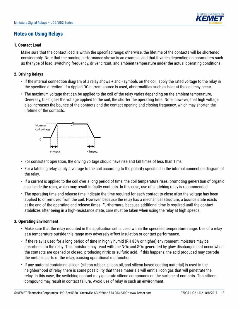
• Iftheinternalconnectiondiagramofarelayshows+and-symbolsonthecoil,applytheratedvoltagetotherelayinthespecifieddirection.IfarippledDCcurrentsourceisused,abnormalitiessuchasheatatthecoilmayoccur.
• The maximum voltage that can be applied to the coil of the relay varies depending on the ambient temperature. Generally, the higher the voltage applied to the coil, the shorter the operating time. Note, however, that high voltage also increases the bounce of the contacts and the contact opening and closing frequency, which may shorten the lifetime of the contacts.
• For consistent operation, the driving voltage should have rise and fall times of less than 1 ms.
• Foralatchingrelay,applyavoltagetothecoilaccordingtothepolarityspecifiedintheinternalconnectiondiagramofthe relay.
• If a current is applied to the coil over a long period of time, the coil temperature rises, promoting generation of organic gas inside the relay, which may result in faulty contacts. In this case, use of a latching relay is recommended.
• The operating time and release time indicate the time required for each contact to close after the voltage has been applied to or removed from the coil. However, because the relay has a mechanical structure, a bounce state exists at the end of the operating and release times. Furthermore, because additional time is required until the contact stabilizes after being in a high-resistance state, care must be taken when using the relay at high speeds.
3. Operating Environment
• Makesurethattherelaymountedintheapplicationsetisusedwithinthespecifiedtemperaturerange.Useofarelayat a temperature outside this range may adversely affect insulation or contact performance.
• Iftherelayisusedforalongperiodoftimeinhighlyhumid(RH85%orhigher)environment,moisturemaybeabsorbed into the relay. This moisture may react with the NOx and SOx generated by glow discharges that occur when the contacts are opened or closed, producing nitric or sulfuric acid. If this happens, the acid produced may corrode the metallic parts of the relay, causing operational malfunction.
• If any material containing silicon (silicon rubber, silicon oil, and silicon based coating material) is used in the neighborhood of relay, there is some possibility that these materials will emit silicon gas that will penetrate the relay. In this case, the switching contact may generate silicon compounds on the surface of contacts. This silicon compound may result in contact failure. Avoid use of relay in such an environment.
All specifications in this catalog and production status of products are subject to change without notice. Prior to the purchase, please contact NEC TOKIN for updated product data. Please request for a specification sheet for detailed product data prior to the purchase. Before using the product in this catalog, please read "Precautions" and other safety precautions listed in the printed version catalog.
2007.08.03 P0886EMDD03VOL01E
EA2/EBE2 SERIES
13
NOTE ON CORRECT USE 1. Notes on contact load Make sure that the contact load is within the specified range; otherwise, the lifetime of the contacts will be shortened considerably. Note that the running performance shown is an example, and that it varies depending on parameters such as the type of load, switching frequency, driver circuit, and ambient temperature under the actual operating conditions. Evaluate the performance by using the actual circuit before using the relay. 2. Driving relays - If the internal connection diagram of a relay shows + and - symbols on the coil, apply the rated voltage to the relay in the specified direction. If a rippled DC current source is used, abnormalities such as beat at the coil may occur. - The maximum voltage that can be applied to the coil of the relay varies depending on the ambient temperature. Generally, the higher the voltage applied to the coil, the shorter the operating time. Note, however, that a high voltage also increases the bounce of the contacts and the contact opening and closing frequency, which may shorten the lifetime of the contacts. - If the driving voltage waveform of the relay coil rises and falls gradually, the inherent performance of the relay may not be fully realized. Make sure that the voltage waveform instantaneously rises and falls as a pulse. - For a latching relay, apply a voltage to the coil according to the polarity specified in the internal connection diagram of the relay. - If a current is applied to the coil over a long period of time, the coil temperature rises, promoting generation of organic gas inside the relay, which may result in faulty contacts. In this case, use of a latching relay is recommended. - The operating time and release time indicate the time required for each contact to close after the voltage has been applied to or removed from the coil. However, because the relay has a mechanical structure, a bounce state exists at the end of the operating and release times. Furthermore, because additional time is required until the contact stabilizes after being in a high-resistance state, care must be taken when using the relay at high speeds. 3. Operating environment - Make sure that the relay mounted in the application set is used within the specified temperature range. Use of a relay
at a temperature outside this range may adversely affect insulation or contact performance. - If the relay is used for a long period of time in highly humid (RH 85% or higher) environment, moisture may be absorbed into the relay. This moisture may react with the NOx and SOx generated by glow discharges that occur when the contacts are opened or closed, producing nitric or sulfuric acid. If this happens, the acid produced may corrode the metallic parts of the relay, causing operational malfunction. - If any material containing silicon (silicon rubber, silicon oil, and silicon based coating material) is used in the neighborhood of relay, there is some possibility that these materials will emit silicon gas that will penetrate the relay. In this case, the switching contact may generate silicon compounds on the surface of contacts. This silicon compound may result in contact failure. Avoid use of relay in such an environment. - Because the operating temperature range varies depending on the humidity, use the relay in the temperature range illustrated in the figure below. Prevent the relay from being frozen and avoid the generation of condensation. - The relay maintains constant sealability under normal atmospheric pressure (810 to 1,200 hpa). Its sealability may be degraded or the relay may be deformed and malfunction if it is used under barometric conditions exceeding the specified range. - The same applies when the relay is stored or transported. Keep the upper-limit value of the temperature to which the relay is exposed after it is removed from the carton box to within 50°C. - Permanent magnets are used in polarized relays. For this reason, when magnets, transformers, or speakers are located nearby the relay characteristics may change and faulty operations may result. - If excessive vibration or shock is applied to the relay, it may malfunction and the contacts remain closed. Vibration or shock applied to the relay during operation may cause considerable damage to or wearing of the contacts. Note that operation of a snap switch mounted close to the relay or shock due to the operation of magnetic solenoid may also cause malfunctioning.
Nominal coil voltage
0
<1msec. <1msec.
-60 -40 -20 0 20 40 60 80 100
80
Temperature (°C )
60
40
20
85
5
Humidity (%RH)
14© KEMET Electronics Corporation • P.O. Box 5928 • Greenville, SC 29606 • 864-963-6300 • www.kemet.com R7005_UC2_UD2 • 8/8/2017
Miniature Signal Relays – UC2/UD2 Series
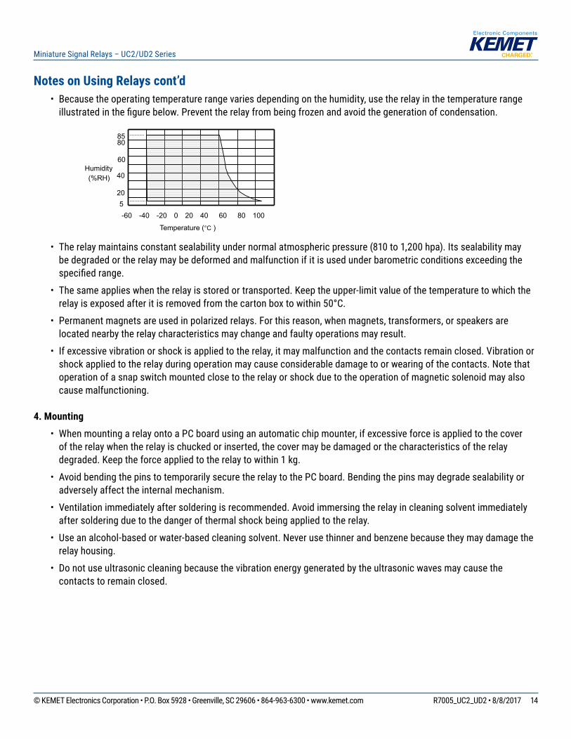
Notes on Using Relays cont’d• Because the operating temperature range varies depending on the humidity, use the relay in the temperature range illustratedinthefigurebelow.Preventtherelayfrombeingfrozenandavoidthegenerationofcondensation.
• The relay maintains constant sealability under normal atmospheric pressure (810 to 1,200 hpa). Its sealability may be degraded or the relay may be deformed and malfunction if it is used under barometric conditions exceeding the specifiedrange.
• The same applies when the relay is stored or transported. Keep the upper-limit value of the temperature to which the relay is exposed after it is removed from the carton box to within 50°C.
• Permanent magnets are used in polarized relays. For this reason, when magnets, transformers, or speakers are located nearby the relay characteristics may change and faulty operations may result.
• If excessive vibration or shock is applied to the relay, it may malfunction and the contacts remain closed. Vibration or shock applied to the relay during operation may cause considerable damage to or wearing of the contacts. Note that operation of a snap switch mounted close to the relay or shock due to the operation of magnetic solenoid may also cause malfunctioning.
4. Mounting
• When mounting a relay onto a PC board using an automatic chip mounter, if excessive force is applied to the cover of the relay when the relay is chucked or inserted, the cover may be damaged or the characteristics of the relay degraded. Keep the force applied to the relay to within 1 kg.
• Avoid bending the pins to temporarily secure the relay to the PC board. Bending the pins may degrade sealability or adversely affect the internal mechanism.
• Ventilation immediately after soldering is recommended. Avoid immersing the relay in cleaning solvent immediately after soldering due to the danger of thermal shock being applied to the relay.
• Use an alcohol-based or water-based cleaning solvent. Never use thinner and benzene because they may damage the relay housing.
• Do not use ultrasonic cleaning because the vibration energy generated by the ultrasonic waves may cause the contacts to remain closed.
All specifications in this catalog and production status of products are subject to change without notice. Prior to the purchase, please contact NEC TOKIN for updated product data. Please request for a specification sheet for detailed product data prior to the purchase. Before using the product in this catalog, please read "Precautions" and other safety precautions listed in the printed version catalog.
2007.08.03 P0886EMDD03VOL01E
EA2/EBE2 SERIES
13
NOTE ON CORRECT USE 1. Notes on contact load Make sure that the contact load is within the specified range; otherwise, the lifetime of the contacts will be shortened considerably. Note that the running performance shown is an example, and that it varies depending on parameters such as the type of load, switching frequency, driver circuit, and ambient temperature under the actual operating conditions. Evaluate the performance by using the actual circuit before using the relay. 2. Driving relays - If the internal connection diagram of a relay shows + and - symbols on the coil, apply the rated voltage to the relay in the specified direction. If a rippled DC current source is used, abnormalities such as beat at the coil may occur. - The maximum voltage that can be applied to the coil of the relay varies depending on the ambient temperature. Generally, the higher the voltage applied to the coil, the shorter the operating time. Note, however, that a high voltage also increases the bounce of the contacts and the contact opening and closing frequency, which may shorten the lifetime of the contacts. - If the driving voltage waveform of the relay coil rises and falls gradually, the inherent performance of the relay may not be fully realized. Make sure that the voltage waveform instantaneously rises and falls as a pulse. - For a latching relay, apply a voltage to the coil according to the polarity specified in the internal connection diagram of the relay. - If a current is applied to the coil over a long period of time, the coil temperature rises, promoting generation of organic gas inside the relay, which may result in faulty contacts. In this case, use of a latching relay is recommended. - The operating time and release time indicate the time required for each contact to close after the voltage has been applied to or removed from the coil. However, because the relay has a mechanical structure, a bounce state exists at the end of the operating and release times. Furthermore, because additional time is required until the contact stabilizes after being in a high-resistance state, care must be taken when using the relay at high speeds. 3. Operating environment - Make sure that the relay mounted in the application set is used within the specified temperature range. Use of a relay
at a temperature outside this range may adversely affect insulation or contact performance. - If the relay is used for a long period of time in highly humid (RH 85% or higher) environment, moisture may be absorbed into the relay. This moisture may react with the NOx and SOx generated by glow discharges that occur when the contacts are opened or closed, producing nitric or sulfuric acid. If this happens, the acid produced may corrode the metallic parts of the relay, causing operational malfunction. - If any material containing silicon (silicon rubber, silicon oil, and silicon based coating material) is used in the neighborhood of relay, there is some possibility that these materials will emit silicon gas that will penetrate the relay. In this case, the switching contact may generate silicon compounds on the surface of contacts. This silicon compound may result in contact failure. Avoid use of relay in such an environment. - Because the operating temperature range varies depending on the humidity, use the relay in the temperature range illustrated in the figure below. Prevent the relay from being frozen and avoid the generation of condensation. - The relay maintains constant sealability under normal atmospheric pressure (810 to 1,200 hpa). Its sealability may be degraded or the relay may be deformed and malfunction if it is used under barometric conditions exceeding the specified range. - The same applies when the relay is stored or transported. Keep the upper-limit value of the temperature to which the relay is exposed after it is removed from the carton box to within 50°C. - Permanent magnets are used in polarized relays. For this reason, when magnets, transformers, or speakers are located nearby the relay characteristics may change and faulty operations may result. - If excessive vibration or shock is applied to the relay, it may malfunction and the contacts remain closed. Vibration or shock applied to the relay during operation may cause considerable damage to or wearing of the contacts. Note that operation of a snap switch mounted close to the relay or shock due to the operation of magnetic solenoid may also cause malfunctioning.
Nominal coil voltage
0
<1msec. <1msec.
-60 -40 -20 0 20 40 60 80 100
80
Temperature (°C )
60
40
20
85
5
Humidity (%RH)
15© KEMET Electronics Corporation • P.O. Box 5928 • Greenville, SC 29606 • 864-963-6300 • www.kemet.com R7005_UC2_UD2 • 8/8/2017
Miniature Signal Relays – UC2/UD2 Series
Notes on Using Relays cont’d
5. Handling and Storage
• Relays are packaged in magazine cases for shipment. If a space is created in the case after some relays have been removed, be sure to insert a stopper to secure the remaining relays in the case. If relays are not well secured, vibration during transportation may cause malfunctioning of the contacts.
• Exercise care in handling the relay so as to avoid dropping it or allowing it to fall. Do not use a relay that has been dropped.Ifarelaydropsfromaworkbenchtothefloor,ashockof9,800m/s2 (1,000 G) or more is applied to the relay, possibly damaging its functions. Even if a light shock has been applied to the relay, thoroughly evaluate its operation before using it.
• Latching relays are factory-set to reset state for shipment. A latching relay may be set, however, by vibration or shock applied while being transported. Be sure to forcibly reset the relay before using it in the application set. Also note that the relay may be set by unexpected vibration or shock when it is used in a portable set.
• The sealability of a surface mount (SMT) relay may be lost if the relay absorbs and is then heated during soldering. When storing relays, therefore, observe the following points:
1. Forstandardpacking,pleaseuserelayswithin12monthsafterdelivery(storageconditions:30°C/60%RH).Iftherelays have moisture absorption, dehumidify as follows:
–TapePackaging:50±5°C,200–300hours.
–SimpleRelay:85±5°C,48hours.
2. ForMBBpacking,pleaseuserelayswithin2yearsafterdelivery(storageconditions:30°C/60%RH).AfteropeningMBBpacking,pleaseusewithin3months(storageconditions:30°C/60%RH).
16© KEMET Electronics Corporation • P.O. Box 5928 • Greenville, SC 29606 • 864-963-6300 • www.kemet.com R7005_UC2_UD2 • 8/8/2017
Miniature Signal Relays – UC2/UD2 Series
KEMET Electronics Corporation Sales Offi ces
Foracompletelistofourglobalsalesoffices,pleasevisitwww.kemet.com/sales.
DisclaimerAllproductspecifications,statements,informationanddata(collectively,the“Information”)inthisdatasheetaresubjecttochange.Thecustomerisresponsibleforchecking and verifying the extent to which the Information contained in this publication is applicable to an order at the time the order is placed.
All Information given herein is believed to be accurate and reliable, but it is presented without guarantee, warranty, or responsibility of any kind, expressed or implied.
StatementsofsuitabilityforcertainapplicationsarebasedonKEMETElectronicsCorporation’s(“KEMET”)knowledgeoftypicaloperatingconditionsforsuchapplications,butarenotintendedtoconstitute–andKEMETspecificallydisclaims–anywarrantyconcerningsuitabilityforaspecificcustomerapplicationoruse.The Information is intended for use only by customers who have the requisite experience and capability to determine the correct products for their application. Any technical advice inferred from this Information or otherwise provided by KEMET with reference to the use of KEMET’s products is given gratis, and KEMET assumes no obligation or liability for the advice given or results obtained.
Although KEMET designs and manufactures its products to the most stringent quality and safety standards, given the current state of the art, isolated component failures may still occur. Accordingly, customer applications which require a high degree of reliability or safety should employ suitable designs or other safeguards (such as installation of protective circuitry or redundancies) in order to ensure that the failure of an electrical component does not result in a risk of personal injury or property damage.
Although all product–related warnings, cautions and notes must be observed, the customer should not assume that all safety measures are indicted or that other measures may not be required.
KEMET is a registered trademark of KEMET Electronics Corporation.