Embed Size (px)
Citation preview

10/12/21
Mini Round Baler
SRB-870
Operator’s Manual

2
Mini Round Baler SRB-870
Page left blank intentionally
3
Mini Round Baler SRB-870
TO THE DEALER:
Assembly and proper installation of this product is the responsibility of the Tar River dealer. Read manual in-
structions and safety rules. Make sure all items on the Dealer’s Pre-Delivery and Delivery Check Lists in the
Owner’s/Operator’s Manual are completed before releasing equipment to the owner.
TO THE OWNER:
Read this manual before operating your Tar River equipment. The information presented will prepare you to
do a better and safer job. Keep this manual handy for ready reference. Require all operators to read this manual
carefully and become acquainted with all the adjustment and operating procedures before attempting to oper-
ate. Replacement manuals can be obtained from your selling dealer. The equipment you have purchased has
been carefully engineered and manufactured to provide dependable and satisfactory use. Like all mechanical
products, it will require cleaning and upkeep. Lubricate the unit as specified. Observe all safety information in
this manual and safety decals on the equipment. For service, your authorized Tar River dealer has trained me-
chanics, genuine Tar River service parts, and the necessary tools and equipment to handle all your needs. Use
only genuine Tar River service parts. Substitute parts will void the warranty and may not meet standards re-
quired for safe and satisfactory operation.
Record your implement model and serial number in the space provide below. Your dealer will need this infor-
mation to give you prompt, efficient service.
Model Number: ______________________________________
Serial Number: _______________________________________
Date Purchased: ______________________________________
4
Mini Round Baler SRB-870
Important Safety Information
Safety
It is important that you read the entire manual and to become familiar with this product before you begin using
it. This product is designed for certain applications only. The manufacturer cannot be responsible for issues
arising from modification. We strongly recommend this product not be modified and /or used for any applica-
tion other than that for which it is designed. If you have any questions relative to a particular application, DO
NOT use the product until you have first contacted us to determine if it can or should be performed on the
product.
Read and understand this manual and all safety signs before operating and maintaining . Review the safety in-
structions and precautions annually.
Safety Signal Words
TAKE NOTE! This safety alert symbol found though out this manual is used to call you attention to in-
structions involving you personal safety and the safety of others. Failure to follow these instructions can
result in injury or death.
This symbol means:
Attention!
Become alert!
Your safety is involved!
Note the use of the signal words, DANGER, WARNING and CAUTION with the safety messag-
es. The appropriate signal word for each has been selected using the following guidelines:
DANGER: Indicates an imminently hazardous situation that, if not avoided, will result in death or
serious injury. This signal word is to be limited to the most extreme situations typically for machine
components which, for functional purposes, cannot be guarded.
WARNING: Indicates a potentially hazardous situation that, if not avoided, could result in death or
serious injury, and includes hazards that are exposed when guards are removed. It may also be used
to alert against unsafe practices.
CAUTION: Indicates a potentially hazardous situation that, if not avoided, may result in minor or
moderate injury. It may also be used to alert against unsafe practices.
5
Mini Round Baler SRB-870
Important Safety Information
General Safety Guidelines
Safety of the operator is one of the main concerns in designing and developing a new piece of equipment. De-
signers and manufacturers build in as many safety features as possible. However, every year many accidents
occur which could have been avoided by a few seconds of thought and a more careful approach to handling
equipment. You, the operator, can avoid many accidents by observing the following precautions in this section.
To avoid personal injury, study the following precautions and insist those working with you, or for you, follow
them.
Replace any DANGER, WARNING, CAUTION or instruction safety decal that is not readable or is missing.
Location of such decals are indicated in this manual. Do not attempt to operate this equipment under the influ-
ence of drugs or alcohol.
Review the safety instructions with all users annually.
This equipment is dangerous to children and persons unfamiliar with its operation. The operator should be a
responsible adult familiar with farm machinery and trained in this equipment’s operations. Do not allow per-
sons to operate or assemble this unit until they have read this manual and have developed a thorough
understanding of the safety precautions and of how it works.
To prevent injury of death, use a tractor equipped with a Roll Over Protection System (ROPS). Do not paint
over, remove or deface any signs or warning decals on your equipment. Observe all safety signs and practice
the instructions on them.
Never exceed the limits of a piece of machinery. If its ability to do a job, or to do so safely, is in question -
Don’t try it!
• Keep safety signs clean and legible at all times.
• Replace safety signs that are missing or have become illegible.
• Replaced parts that displayed a safety sign should also display the current safety sign
• Safety signs are available from your Distributor or Dealer Parts Department or the factory.
Safety Decal Care
6
Mini Round Baler SRB-870
Important Safety Information
How to install Safety Signs:
• Be sure that the installation area is clean and dry.
• Decide on the exact position before you remove the backing paper.
• Remove the smallest portion of the split backing paper.
• Align the decal over the specified area and carefully press the small portion with the exposed sticky back-
ing in place.
• Slowly peel back the remaining paper and carefully smooth the remaining portion of the decal in place.
• Small air pockets can be pierced with a pin and smoothed out using the piece of decal backing paper.
• Carefully study and understand this manual.
• Do not wear loose-fitting clothing, which may catch in moving parts.
• Always wear protective clothing and substantial shoes.
• Assure that all tires are inflated evenly.
• Give the unit a visual inspection for any loose bolts, worn parts or cracked welds, and make necessary re-
pairs. Follow the maintenance safety instructions included with this manual.
• Be sure that there are no tools lying on or in the equipment.
• Do not use the unit until you are sure that the area is clear, especially of children and animals.
• Don’t hurry the learning process or take the unit for granted. Ease into it and become familiar with your
new equipment.
• Practice operation of your equipment and its attachments. Completely familiarize yourself and other opera-
tors with its operation before using.
• Use a tractor equipped with a Roll Over Protection System (ROPS) and fasten your seat belt prior to start-
ing engine.
• The manufacturer does not recommend usage of tractor with ROPS removed.
• Move tractor wheels to the widest recommended settings to increase stability.
• Securely attach to towing unit. Use a high strength, appropriately sized hitch pin with a mechanical retainer
and attach safety chain.
• Do not allow anyone to stand between the tongue or hitch and the towing vehicle when backing up to the
equipment.
• Do not use the unit until you are sure that the area is clear, especially of children and animals.
Before Operation
7
Mini Round Baler SRB-870
Important Safety Information
• Children should not be allowed on the machine.
• Clear the area of small children and bystanders before moving the machine.
• If using a towing unit, securely attach feeder by using a hardened 3/4” pin, a metal retainer, and safety
chains if required. Shift towing unit to a lower gear before going down steep downgrades, thus using the
engine as a retarding force. Keep towing vehicle in gear at all times. Slow down for corners and rough ter-
rain.
• Make sure you are in compliance with all local and state regulations regarding transporting equipment on
public roads and highways. Lights and slow moving signs must be clean and visible by overtaking or on-
coming traffic when machine is transported.
• Beware of bystanders, particularly children! Always look around to make sure that it is safe to start the
engine of the towing vehicle or move the unit. This is particularly important with higher noise levels and
quiet cabs, as you may not hear people shouting.
• NO PASSENGERS ALLOWED! Do not carry passengers anywhere on, or in, the tractor or equipment,
except as required for operation.
• Keep hands and clothing clear of moving parts.
• Do not clean, lubricate or adjust your equipment while it is moving.
• When halting operation, even periodically, set the tractor or towing vehicle brakes, disengage the PTO,
shut off the engine and remove the ignition key.
• Be especially observant of the operating area and terrain. Watch for holes, rocks or hidden hazards. Always
inspect the area prior to operation.
• DO NOT operate near the edge of drop-offs or banks.
• DO NOT operate on steep slopes as overturns may result.
• Operate up and down (not across) intermediate slopes. Avoid sudden starts and stops.
During Operation
8
Mini Round Baler SRB-870
Important Safety Information
• Adopt safe driving practices.
• Keep the brake pedals latched together at all times. Never use independent braking with machine in tow
as loss of control and/or upset of unit can result.
• Always drive at a safe speed relative to local conditions and ensure that your speed is low enough for an
emergency stop to be safe and secure. Keep speed at a minimum.
• Reduce speed prior to turns to avoid the risk of overturning.
• Avoid sudden uphill turns on steep slopes.
• Always keep the tractor or towing vehicle in gear to provide engine braking when going downhill. Do not
coast.
• Do not drink and drive!
• Comply with state and local laws governing highway safety and movement of farm machinery on public
roads.
• Use approved accessory lighting, flags and necessary warning devices to protect operators of other vehicles
on the highway during daylight and nighttime transport. Various safety lights and devices are available
from your dealer.
• The use of flashing amber lights is acceptable in most localities. However, some localities prohibit their
use. Local laws should be checked for all highway and marking requirements.
• When driving the tractor and equipment on the road or highway under 40 kph (20 mph) at night or during
the day, use the amber warning lights and a slow moving vehicle (SMV) identification emblem.
• Plan your route to avoid heavy traffic.
• Be a safe and courteous driver. Always yield to oncoming traffic in all situations, including narrow bridg-
es, intersections, etc.
• Be observant of bridge loading ratings. Do not cross bridges rated at lower than the gross weight at which
you are operating.
• Watch for obstructions overhead and to the side while transporting.
• Always operate in a position to provide maximum visibility at all times. Make allowances for increased
length and weight of the equipment when making turns, stopping the unit, etc.
• Pick the most level route when transporting across fields. Avoid the edges of ditches or gullies and steep
hillsides.
• Be extra careful when working in inclines.
Highway and Transport Operations
9
Mini Round Baler SRB-870
Important Safety Information
• Maneuver the tractor or towing vehicle at safe speeds.
• Avoid overhead wires or other obstacles. Contact with overhead lines could cause serious injury or death.
• Avoid loose fill, rocks and holes, they can be dangerous for equipment operation or movement.
• Allow for unit length when making turns,
• Operate the towing vehicle from the operator’s seat only.
• Never stand alongside of unit with engine running or attempt to start engine and/or operate machine while
standing alongside of unit.
• Never leave running equipment attachments unattended.
• As a precaution, always recheck the hardware on equipment following every 100 hours of operation. Cor-
rect all problems. Follow the maintenance safety procedures.
Highway and Transport Operations
10
Mini Round Baler SRB-870
Assembly
The PTO shaft, twine and electrical connections are located in the twine storage compartment (under the lid at
front of the baler). The wheels are located inside the bale opener door (at rear of the baler). See “Attaching
Wheels” (page 12) for instruction on how to remove wheels from baler chamber.
Attaching to a tractor:
• It is best to attach the baler to the tractor on a level surface.
• Back the tractor to the baler making sure the tractor lower arms are level with the baler’s lower hitch pins.
Caution: Be sure that no one is between the tractor and the baler when backing.
• Secure the tractor’s lower arms to the baler’s lower hitch pins with lynch pins.
• Attach the tractor’s top link to the baler’s upper hitch. Adjust the top link so that the baler is level on the
ground.
• If baler is in the shipping frame, attach baler to tractor using tractor 3-point, remove bolts securing baler to
shipping frame, lift baler, remove and properly discard the shipping frame.
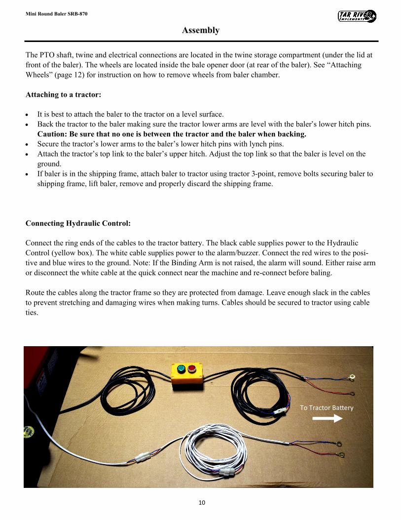
Connecting Hydraulic Control:
Connect the ring ends of the cables to the tractor battery. The black cable supplies power to the Hydraulic
Control (yellow box). The white cable supplies power to the alarm/buzzer. Connect the red wires to the posi-
tive and blue wires to the ground. Note: If the Binding Arm is not raised, the alarm will sound. Either raise arm
or disconnect the white cable at the quick connect near the machine and re-connect before baling.
Route the cables along the tractor frame so they are protected from damage. Leave enough slack in the cables
to prevent stretching and damaging wires when making turns. Cables should be secured to tractor using cable
ties.
To Tractor Battery
11
Mini Round Baler SRB-870
Assembly
Attaching wheels:
The baler wheels are stored inside the baler rolling chamber at the rear of the baler for shipping purposes.
The rear door is opened by the baler hydraulics.
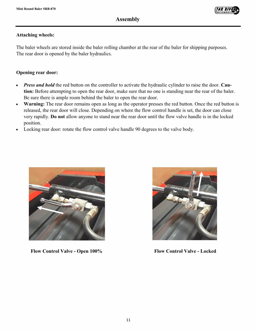
Opening rear door:
• Press and hold the red button on the controller to activate the hydraulic cylinder to raise the door. Cau-
tion: Before attempting to open the rear door, make sure that no one is standing near the rear of the baler.
Be sure there is ample room behind the baler to open the rear door.
• Warning: The rear door remains open as long as the operator presses the red button. Once the red button is
released, the rear door will close. Depending on where the flow control handle is set, the door can close
very rapidly. Do not allow anyone to stand near the rear door until the flow valve handle is in the locked
position.
• Locking rear door: rotate the flow control valve handle 90 degrees to the valve body.
Flow Control Valve - Open 100% Flow Control Valve - Locked
12
Mini Round Baler SRB-870
Assembly
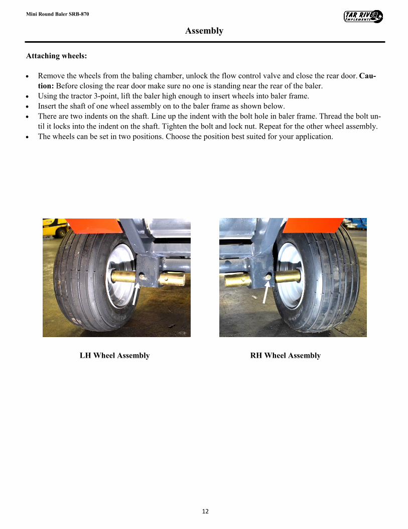
Attaching wheels:
• Remove the wheels from the baling chamber, unlock the flow control valve and close the rear door. Cau-
tion: Before closing the rear door make sure no one is standing near the rear of the baler.
• Using the tractor 3-point, lift the baler high enough to insert wheels into baler frame.
• Insert the shaft of one wheel assembly on to the baler frame as shown below.
• There are two indents on the shaft. Line up the indent with the bolt hole in baler frame. Thread the bolt un-
til it locks into the indent on the shaft. Tighten the bolt and lock nut. Repeat for the other wheel assembly.
• The wheels can be set in two positions. Choose the position best suited for your application.
RH Wheel Assembly LH Wheel Assembly
13
Mini Round Baler SRB-870
Assembly
Attaching the PTO shaft:
Before installing the PTO shaft make sure that the RPM rating and the direction of rotation match those of the
tractor. Carefully read the PTO shaft and tractor instructions. Before operation, make sure that the guards are
installed on the power take off of the tractor and PTO shaft. Make sure that they cover the PTO shaft through-
out its length. Note: The PTO shaft may be too long and require shortening. See “Shortening a PTO
driveline” below.
Press the locking pin on the PTO yoke and slide yoke on to the PTO of the tractor until the pin seats. Pull on
PTO shaft to make certain it is locked in place. Repeat the procedure for the machine end. Attach the PTO
cover’s safety chains to a stationary part of the tractor. Leave some slack in the chain to accommodate move-
ment.
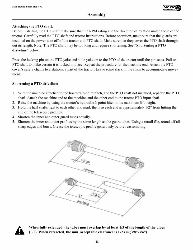
Shortening a PTO driveline:
1. With the machine attached to the tractor’s 3-point hitch, and the PTO shaft not installed, separate the PTO
shaft. Attach the machine end to the machine and the other end to the tractor PTO input shaft.
2. Raise the machine by using the tractor’s hydraulic 3-point hitch to its maximum lift height.
3. Hold the half shafts next to each other and mark them so each end is approximately 1/2” from hitting the
end of the telescopic profiles.
4. Shorten the inner and outer guard tubes equally.
5. Shorten the inner and outer profiles by the same length as the guard tubes. Using a rattail file, round off all
sharp edges and burrs. Grease the telescopic profile generously before reassembling.
When fully extended, the tubes must overlap by at least 1/3 of the length of the pipes
(LT). When retracted, the min. acceptable clearance is 1-2 cm (3/8”-3/4”)
14
Mini Round Baler SRB-870
Assembly
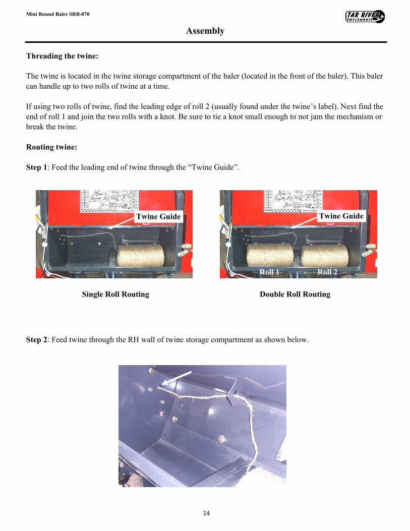
Threading the twine:
The twine is located in the twine storage compartment of the baler (located in the front of the baler). This baler
can handle up to two rolls of twine at a time.
If using two rolls of twine, find the leading edge of roll 2 (usually found under the twine’s label). Next find the
end of roll 1 and join the two rolls with a knot. Be sure to tie a knot small enough to not jam the mechanism or
break the twine.
Routing twine:
Step 1: Feed the leading end of twine through the “Twine Guide”.
Step 2: Feed twine through the RH wall of twine storage compartment as shown below.
Single Roll Routing Double Roll Routing
Twine Guide
Roll 2 Roll 1
Twine Guide
15
Mini Round Baler SRB-870
Assembly
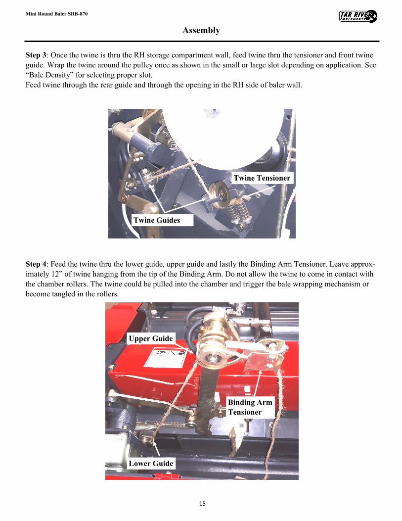
Step 3: Once the twine is thru the RH storage compartment wall, feed twine thru the tensioner and front twine
guide. Wrap the twine around the pulley once as shown in the small or large slot depending on application. See
“Bale Density” for selecting proper slot.
Feed twine through the rear guide and through the opening in the RH side of baler wall.
Step 4: Feed the twine thru the lower guide, upper guide and lastly the Binding Arm Tensioner. Leave approx-
imately 12” of twine hanging from the tip of the Binding Arm. Do not allow the twine to come in contact with
the chamber rollers. The twine could be pulled into the chamber and trigger the bale wrapping mechanism or
become tangled in the rollers.
Twine Tensioner
Twine Guides
Lower Guide
Upper Guide
Binding Arm
Tensioner
16
Mini Round Baler SRB-870
Operating Instructions
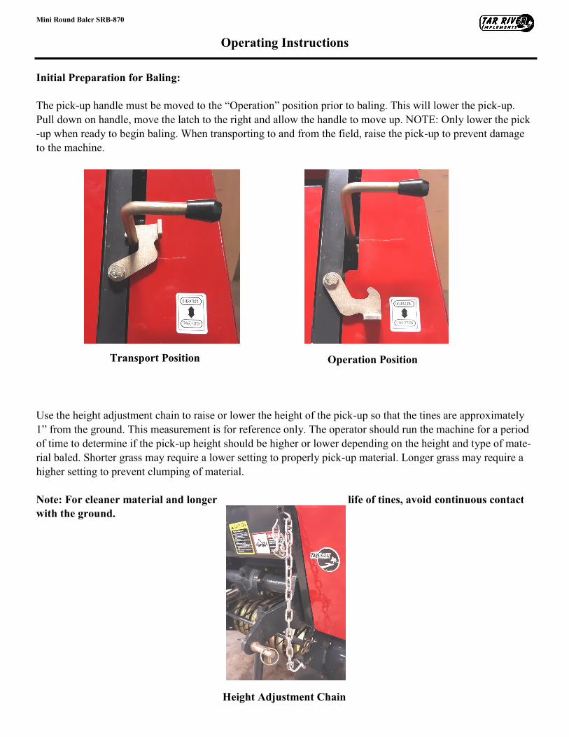
Initial Preparation for Baling:
The pick-up handle must be moved to the “Operation” position prior to baling. This will lower the pick-up.
Pull down on handle, move the latch to the right and allow the handle to move up. NOTE: Only lower the pick
-up when ready to begin baling. When transporting to and from the field, raise the pick-up to prevent damage
to the machine.
Use the height adjustment chain to raise or lower the height of the pick-up so that the tines are approximately
1” from the ground. This measurement is for reference only. The operator should run the machine for a period
of time to determine if the pick-up height should be higher or lower depending on the height and type of mate-
rial baled. Shorter grass may require a lower setting to properly pick-up material. Longer grass may require a
higher setting to prevent clumping of material.
Note: For cleaner material and longer life of tines, avoid continuous contact
with the ground.
Transport Position
Height Adjustment Chain
Operation Position
17
Mini Round Baler SRB-870
Operating Instructions
Baling:
• Line up tractor with the first windrow. Engage the tractor’s PTO and begin baling.
• Slowly drive over the windrow. It is recommended to drive the tractor 2-3 miles per hour for best results.
However, speed can depend on type of material baling, field conditions and size of windrow.
• Continuously monitor the pick-up. If material is gathering up in front of the pick-up, slow down or stop
tractor to allow the baler to catch up and pick up the excess material.
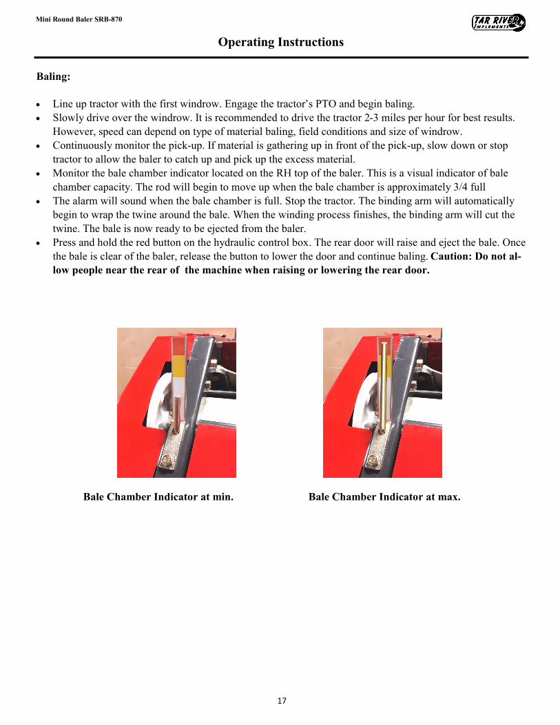
• Monitor the bale chamber indicator located on the RH top of the baler. This is a visual indicator of bale
chamber capacity. The rod will begin to move up when the bale chamber is approximately 3/4 full
• The alarm will sound when the bale chamber is full. Stop the tractor. The binding arm will automatically
begin to wrap the twine around the bale. When the winding process finishes, the binding arm will cut the
twine. The bale is now ready to be ejected from the baler.
• Press and hold the red button on the hydraulic control box. The rear door will raise and eject the bale. Once
the bale is clear of the baler, release the button to lower the door and continue baling. Caution: Do not al-
low people near the rear of the machine when raising or lowering the rear door.
Bale Chamber Indicator at min. Bale Chamber Indicator at max.
18
Mini Round Baler SRB-870
Adjustments
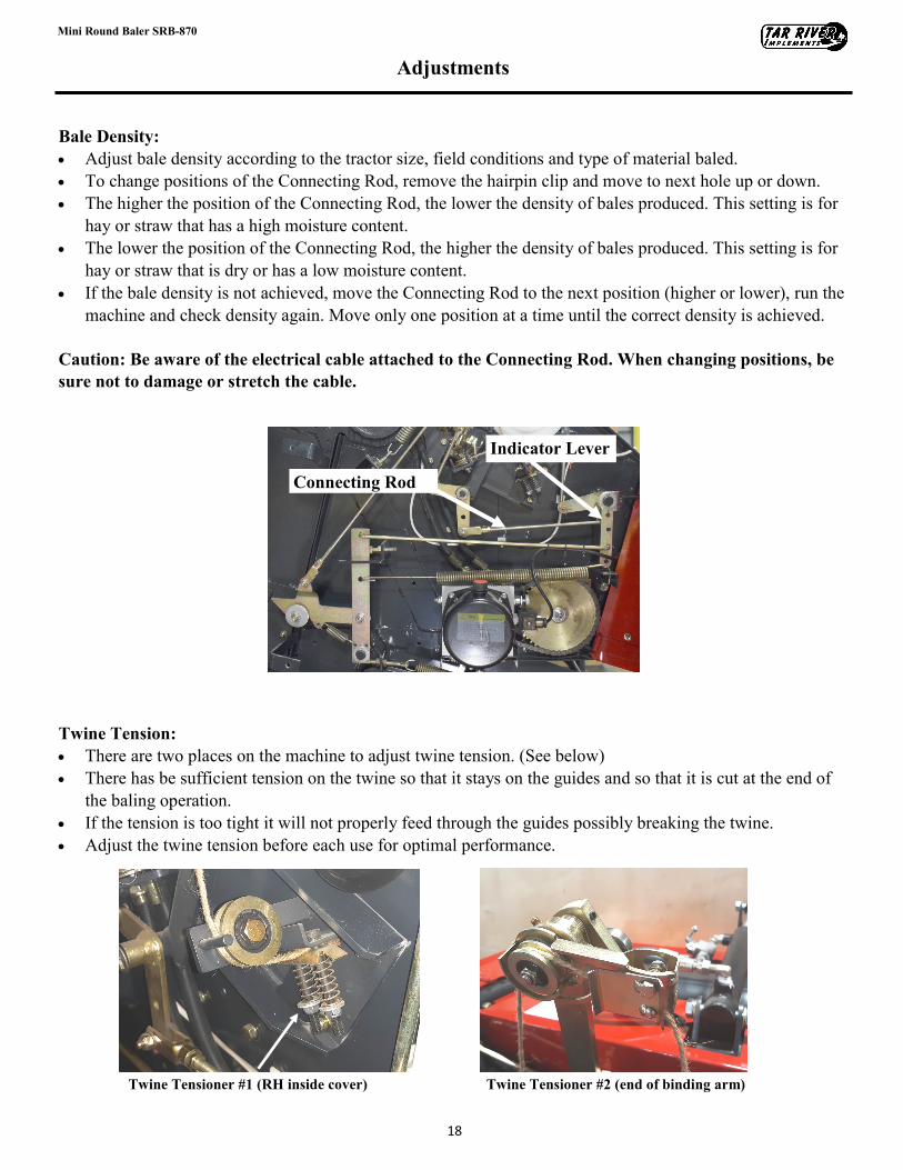
Bale Density:
• Adjust bale density according to the tractor size, field conditions and type of material baled.
• To change positions of the Connecting Rod, remove the hairpin clip and move to next hole up or down.
• The higher the position of the Connecting Rod, the lower the density of bales produced. This setting is for
hay or straw that has a high moisture content.
• The lower the position of the Connecting Rod, the higher the density of bales produced. This setting is for
hay or straw that is dry or has a low moisture content.
• If the bale density is not achieved, move the Connecting Rod to the next position (higher or lower), run the
machine and check density again. Move only one position at a time until the correct density is achieved.
Caution: Be aware of the electrical cable attached to the Connecting Rod. When changing positions, be
sure not to damage or stretch the cable.
Twine Tension:
• There are two places on the machine to adjust twine tension. (See below)
• There has be sufficient tension on the twine so that it stays on the guides and so that it is cut at the end of
the baling operation.
• If the tension is too tight it will not properly feed through the guides possibly breaking the twine.
• Adjust the twine tension before each use for optimal performance.
Indicator Lever
Connecting Rod
Twine Tensioner #1 (RH inside cover) Twine Tensioner #2 (end of binding arm)
19
Mini Round Baler SRB-870
Adjustments
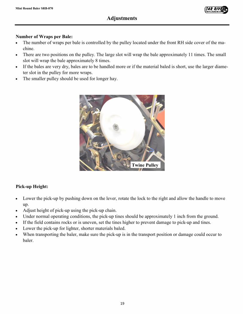
Number of Wraps per Bale:
• The number of wraps per bale is controlled by the pulley located under the front RH side cover of the ma-
chine.
• There are two positions on the pulley. The large slot will wrap the bale approximately 11 times. The small
slot will wrap the bale approximately 8 times.
• If the bales are very dry, bales are to be handled more or if the material baled is short, use the larger diame-
ter slot in the pulley for more wraps.
• The smaller pulley should be used for longer hay.
Pick-up Height:
• Lower the pick-up by pushing down on the lever, rotate the lock to the right and allow the handle to move
up.
• Adjust height of pick-up using the pick-up chain.
• Under normal operating conditions, the pick-up tines should be approximately 1 inch from the ground.
• If the field contains rocks or is uneven, set the tines higher to prevent damage to pick-up and tines.
• Lower the pick-up for lighter, shorter materials baled.
• When transporting the baler, make sure the pick-up is in the transport position or damage could occur to
baler.
Twine Pulley
20
Mini Round Baler SRB-870
Adjustments
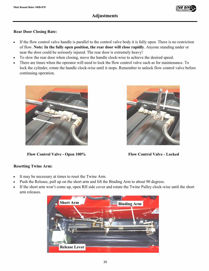
Rear Door Closing Rate:
• If the flow control valve handle is parallel to the control valve body it is fully open. There is no restriction
of flow. Note: In the fully open position, the rear door will close rapidly. Anyone standing under or
near the door could be seriously injured. The rear door is extremely heavy!
• To slow the rear door when closing, move the handle clock-wise to achieve the desired speed.
• There are times when the operator will need to lock the flow control valve such as for maintenance. To
lock the cylinder, rotate the handle clock-wise until it stops. Remember to unlock flow control valve before
continuing operation.
Resetting Twine Arm:
• It may be necessary at times to reset the Twine Arm.
• Push the Release, pull up on the short arm and lift the Binding Arm to about 90 degrees.
• If the short arm won’t come up, open RH side cover and rotate the Twine Pulley clock-wise until the short
arm releases.
Flow Control Valve - Open 100% Flow Control Valve - Locked
Short Arm
Release Lever
Binding Arm
21
Mini Round Baler SRB-870
Adjustments
After Operation:
Follow the guidelines listed below after baling.
• Store the baler under a shelter or in a building out of the weather.
• If left attached to the tractor, lower the baler so that the wheels are touching the ground. Never leave any
implement raised.
• If removing the implement: Take the pressure off the top pin by raising or lowering the tractor 3-point and
remove top link pin. Before disconnecting the lower hitch, pull the pin on the baler parking stand, lower
the stand and insert pin. The baler may be raised or lowered by the 3-point to set the baler parking stand.
• Be sure to chock the baler’s tires to prevent it from rolling and injuring bystanders or damaging equipment.
• Inspect the baler for damage. If any damage is found, make the necessary repairs to keep the baler in opti-
mal operating condition.
• Inspect the baler for loose hardware. Tighten to proper torque specifications.
• Perform any daily maintenance according to “Maintenance Schedule” before operating again.
Recommendations for Consistent Bales:
• Generally a slower the tractor speed will result in denser bales. It is recommended to begin with 2-3 miles
per hour. Adjust speed according to field conditions.
• Windrows should be 28-32 inches wide with a height of 12-16 for best results. Uniform windrows will pro-
duce a more consistent weight of bales and there will be fewer issues during the baling. Many baling issues
are related to material that is too short or too dry.
• The material should be baled when it is 1-3 feet tall and approximate moisture content of 15%.
• Material that is extremely dry will result in bales that are under weight, inconsistent in size and the twine
will not wrap properly.
• Consistent bales are achieved when the material is evenly distributed across the full width of the baler pick
-up.
Caution: The baler must be lifted off the ground before turning at the end of a windrow.
If the baler is not lifted, damage can occur to the tires and wheels. When lifting the bal-
er, lift it high enough to clear the ground by a few inches. Be careful not to lift the baler
so high that it puts the PTO in a bind. Extreme PTO angles can cause damage to the
PTO and the baler gear box.
22
Mini Round Baler SRB-870
Adjustments
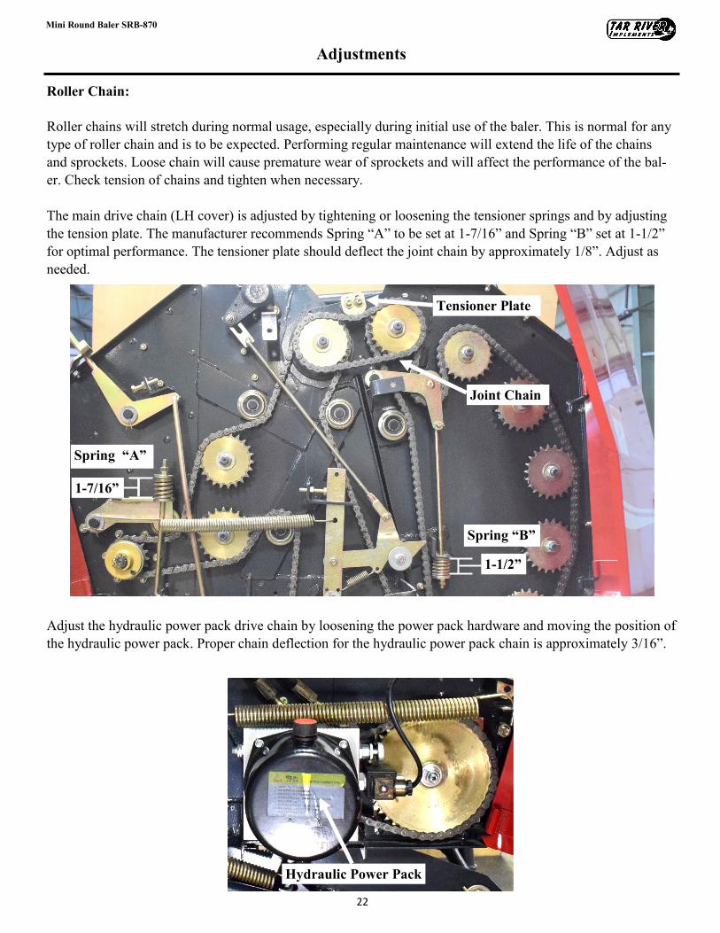
Roller Chain:
Roller chains will stretch during normal usage, especially during initial use of the baler. This is normal for any
type of roller chain and is to be expected. Performing regular maintenance will extend the life of the chains
and sprockets. Loose chain will cause premature wear of sprockets and will affect the performance of the bal-
er. Check tension of chains and tighten when necessary.
The main drive chain (LH cover) is adjusted by tightening or loosening the tensioner springs and by adjusting
the tension plate. The manufacturer recommends Spring “A” to be set at 1-7/16” and Spring “B” set at 1-1/2”
for optimal performance. The tensioner plate should deflect the joint chain by approximately 1/8”. Adjust as
needed.
Adjust the hydraulic power pack drive chain by loosening the power pack hardware and moving the position of
the hydraulic power pack. Proper chain deflection for the hydraulic power pack chain is approximately 3/16”.
Spring “A”
Spring “B”
Tensioner Plate
Joint Chain
1-7/16”
1-1/2”
Hydraulic Power Pack
23
Mini Round Baler SRB-870
Adjustments
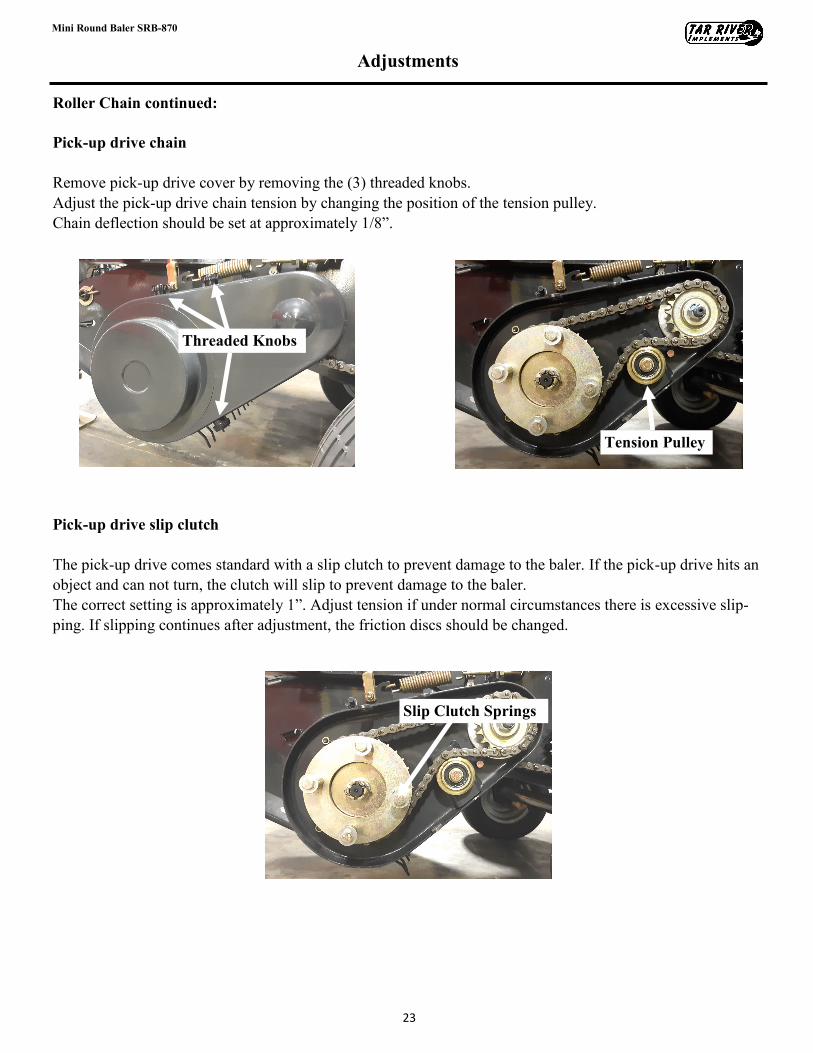
Roller Chain continued:
Pick-up drive chain
Remove pick-up drive cover by removing the (3) threaded knobs.
Adjust the pick-up drive chain tension by changing the position of the tension pulley.
Chain deflection should be set at approximately 1/8”.
Pick-up drive slip clutch
The pick-up drive comes standard with a slip clutch to prevent damage to the baler. If the pick-up drive hits an
object and can not turn, the clutch will slip to prevent damage to the baler.
The correct setting is approximately 1”. Adjust tension if under normal circumstances there is excessive slip-
ping. If slipping continues after adjustment, the friction discs should be changed.
Tension Pulley
Threaded Knobs
Slip Clutch Springs
24
Mini Round Baler SRB-870
Adjustments
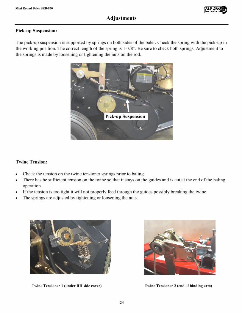
Pick-up Suspension:
The pick-up suspension is supported by springs on both sides of the baler. Check the spring with the pick-up in
the working position. The correct length of the spring is 1-7/8”. Be sure to check both springs. Adjustment to
the springs is made by loosening or tightening the nuts on the rod.
Twine Tension:
• Check the tension on the twine tensioner springs prior to baling.
• There has be sufficient tension on the twine so that it stays on the guides and is cut at the end of the baling
operation.
• If the tension is too tight it will not properly feed through the guides possibly breaking the twine.
• The springs are adjusted by tightening or loosening the nuts.
Pick-up Suspension
Twine Tensioner 1 (under RH side cover) Twine Tensioner 2 (end of binding arm)
25
Mini Round Baler SRB-870
Adjustments
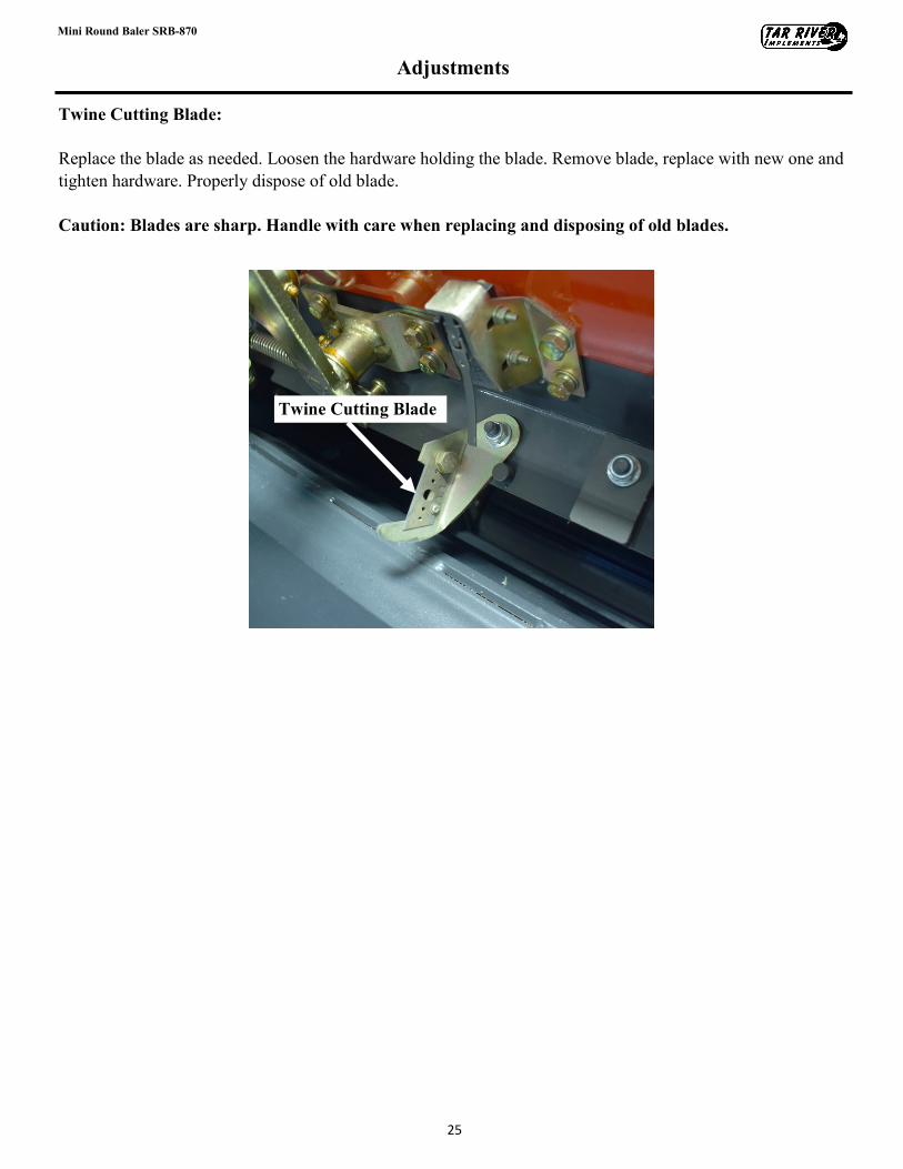
Twine Cutting Blade:
Replace the blade as needed. Loosen the hardware holding the blade. Remove blade, replace with new one and
tighten hardware. Properly dispose of old blade.
Caution: Blades are sharp. Handle with care when replacing and disposing of old blades.
Twine Cutting Blade
26
Mini Round Baler SRB-870
Maintenance
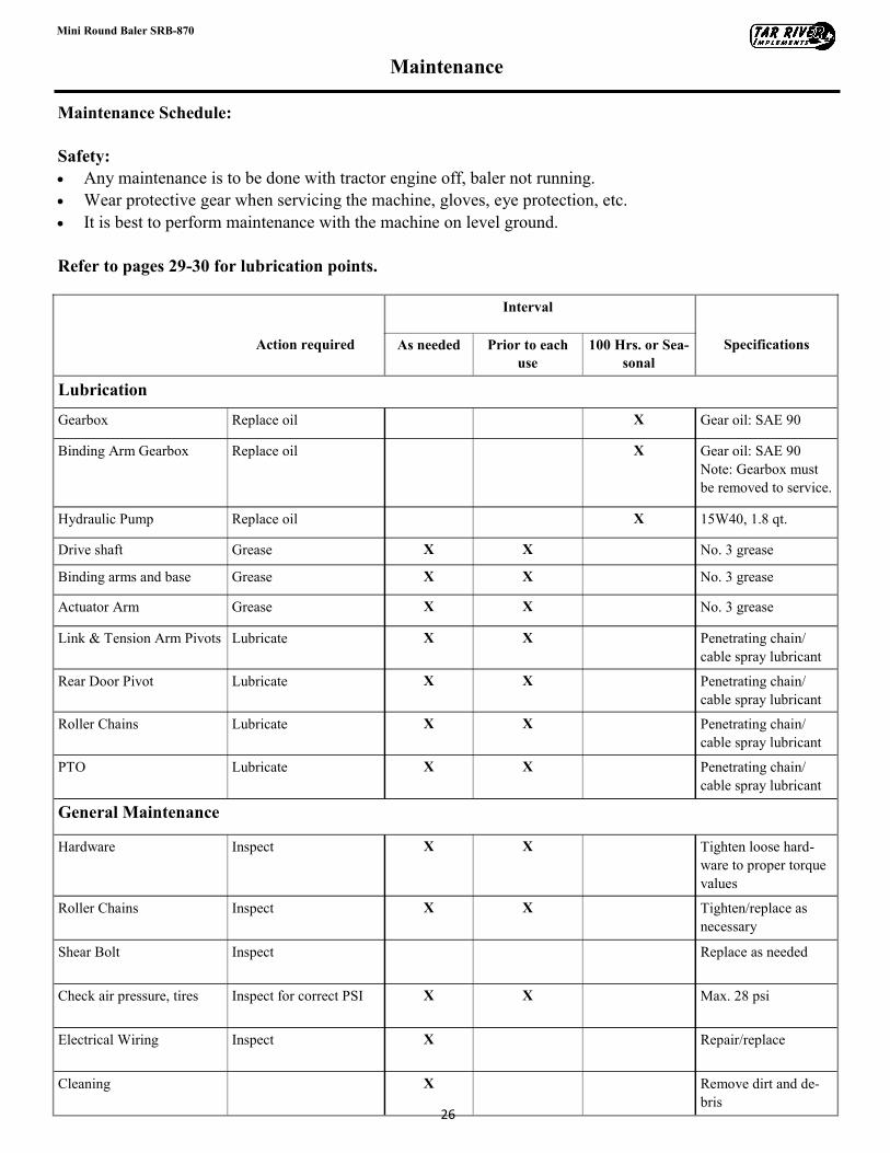
Maintenance Schedule:
Safety:
• Any maintenance is to be done with tractor engine off, baler not running.
• Wear protective gear when servicing the machine, gloves, eye protection, etc.
• It is best to perform maintenance with the machine on level ground.
Refer to pages 29-30 for lubrication points.
Interval
Action required As needed Prior to each
use
100 Hrs. or Sea-
sonal
Specifications
Lubrication
Gearbox Replace oil X Gear oil: SAE 90
Binding Arm Gearbox Replace oil X Gear oil: SAE 90
Note: Gearbox must
be removed to service.
Hydraulic Pump Replace oil X 15W40, 1.8 qt.
Drive shaft Grease X X No. 3 grease
Binding arms and base Grease X X No. 3 grease
Actuator Arm Grease X X No. 3 grease
Link & Tension Arm Pivots Lubricate X X Penetrating chain/
cable spray lubricant
Rear Door Pivot Lubricate X X Penetrating chain/
cable spray lubricant
Roller Chains Lubricate X X Penetrating chain/
cable spray lubricant
PTO Lubricate X X Penetrating chain/
cable spray lubricant
General Maintenance
Hardware Inspect X X Tighten loose hard-
ware to proper torque
values
Roller Chains Inspect X X Tighten/replace as
necessary
Shear Bolt Inspect Replace as needed
Check air pressure, tires Inspect for correct PSI X X Max. 28 psi
Electrical Wiring Inspect X Repair/replace
Cleaning X Remove dirt and de-
bris
27
Mini Round Baler SRB-870
Maintenance
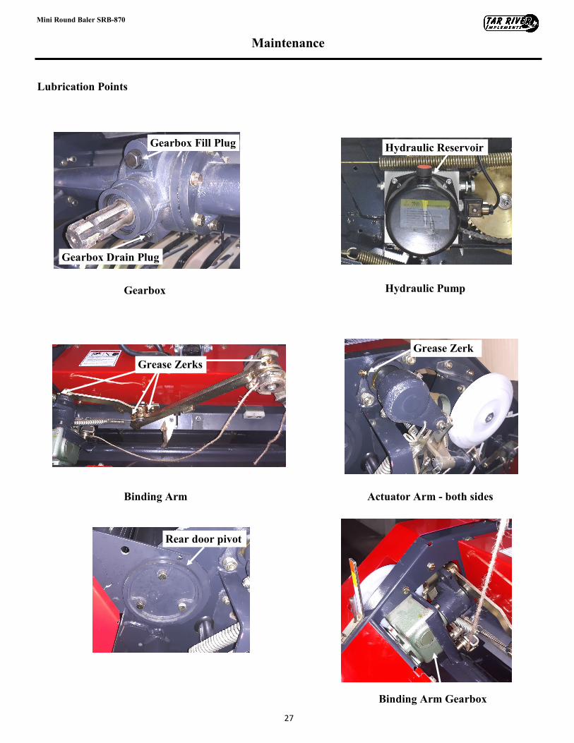
Lubrication Points
Grease Zerk
Rear door pivot
Hydraulic Reservoir Gearbox Fill Plug
Gearbox Drain Plug
Hydraulic Pump Gearbox
Actuator Arm - both sides Binding Arm
Grease Zerks
Binding Arm Gearbox
28
Mini Round Baler SRB-870
Maintenance
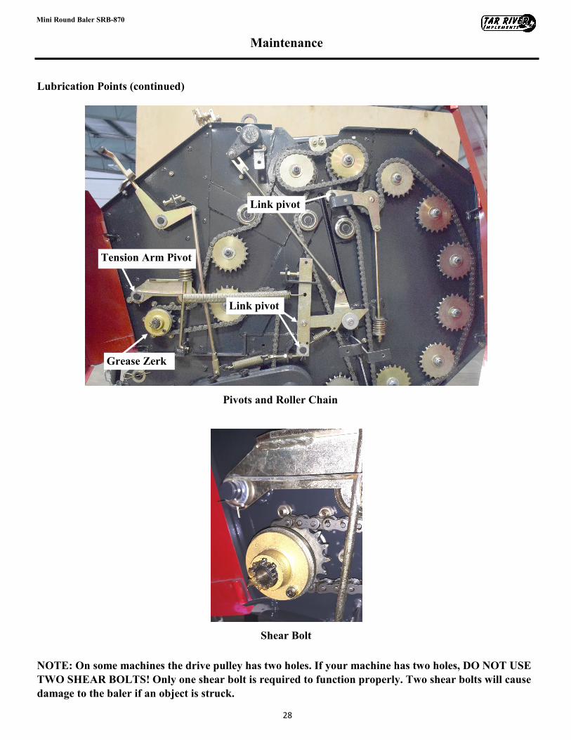
Lubrication Points (continued)
NOTE: On some machines the drive pulley has two holes. If your machine has two holes, DO NOT USE
TWO SHEAR BOLTS! Only one shear bolt is required to function properly. Two shear bolts will cause
damage to the baler if an object is struck.
Link pivot
Tension Arm Pivot
Link pivot
Pivots and Roller Chain
Grease Zerk
Shear Bolt
29
Mini Round Baler SRB-870
Warranty
LIMITED WARRANTY
Belco Resources Equipment warrants to the original purchaser of any new piece of machinery from Belco Re-
sources Equipment, purchased from an authorized Belco Resources Equipment dealer, that the equipment be
free from defects in material and workmanship for a period of one (1) year for non-commercial, state, and mu-
nicipalities’ use, ninety (90) days for commercial use from date of retail sale. Warranty for rental purposes is
thirty (30) days. The obligation of Belco Resources Equipment to the purchaser under this warranty is limited
to the repair or replacement of defective parts.
Replacement or repair parts installed in the equipment covered by this limited warranty are warranted for nine-
ty (90) days from the date of purchase of such part or to the expiration of the applicable new equipment war-
ranty period, whichever occurs later. Warranted parts shall be provided at no cost to the user at an authorized
Belco Resources Equipment dealer during regular working hours. Belco Resources Equipment reserves the
right to inspect any equipment or parts, which are claimed to have been defective in material or workmanship.
This limited warranty does not apply to and excludes wear items such as shear pins, tires, tubes knives, blades
or other wear items. Oil or grease is not covered by this warranty.
All obligations of Belco Resources Equipment under this limited warranty shall be terminated if:
Proper service is not performed on the machine.
The machine is modified or altered in any way.
The machine is being used or has been used for purposes other than those for which the machine was
intended.
DISCLAIMER OF IMPLIED WARRANTIES & CONSEQUENTIAL DAMAGES
Belco Resources Equipment obligation under this limited warranty, to the extent allowed by law, is in lieu of
all warranties, implied or expressed, including implied warranties of merchantability and fitness for a particu-
lar purpose and any liability for incidental and consequential damages with respect to the sale or use of the
items warranted. Such incidental and consequential damages shall include but not be limited to: transportation
charges other than normal freight charges; cost of installation other than cost approved by Belco Resources
Equipment; duty; taxes; charges for normal service or adjustment; loss of crops or any other loss of income;
rental of substitute equipment, expenses due to loss, damage, detention or delay in the delivery.
REGISTRATION
The online Warranty Registration must be completed in order to qualify for coverage on this Limited Warran-
ty. Visit br-equipment.com, click on “Warranty Registration” and completely fill out the form to register the
new piece of equipment.

401 Jeffreys Road Rocky Mount, NC 27804 www.tarrivermfg.com
Tel: 252-822-7140 Fax: 252-787-5855 [email protected]