Embed Size (px)
Citation preview
Users Manual
Mini Plus Ticket PrinterMini Plus Ticket Printer
BOCA SYSTEMS, INC.
© 1996 Boca Systems, Inc. All rights reserved.
Under the copyright laws, this manual may not be copied, in whole or in part, withoutthe written consent of BOCA.
Every effort has been made to ensure that the information in this manual is accurate.BOCA is not responsible for printing or clerical errors and reserves the right to changespecifications without notice.
Table of Contents Page
1.0 Introduction 1
2.0 Unpacking the Printer 2
3.0 A tour of your printer 3-5
4.0 Installation 6
5.0 Configuration 7
6.0. Standard Interface Pinouts 8
7.0 Thermal Paper - Theory and Specification 9
8.0 Maintenance and Adjustments 10-15
9.0 Spare Parts List 16-17
10. Troubleshooting Guide 18-19
Table of Figures and Appendices Page
Figure 1 Packaging 2
Figure 2a Mini Plus Ticket Printer 3
Figure 2b Mini Plus LCD Display 3
Figure 3a Mini Plus side view 4
Figure 3b Mini Plus side view - Electronics Cover Removed 4
Figure 4 Rear view 5
Figure 5 Ticket loading 6
Figure 6 Slider Adjustment for adjustable paper path 7
Figure 7 Optical Devices 11
Figure 8 Print head removal 13
Appendix A Operator Menu options through control panel
Appendix B FGL Printer Comparison Chart

FCC NOTICE
NOTE: The equipment has been tested and found to comply with the limits for a classA digital device, pursuant to part 15 of the FCC rules. These limits are designed toprovide reasonable protection against harmful interference when the equipment isoperated in a commercial environment. This equipment generates, uses, and can radi-ate radio frequency energy and , if not installed and used in accordance with theinstruction manual, may cause harmful interference to radio communications.Operation of this equipment in a residential area is likely to cause harmful interferencein which case the user will be required to correct the interference at his own expense.
Operation is subject to the following two conditions:1. This device may not cause harmful interference, and2. This device must accept any interference received, including interference that may
cause undesired operation.
NOTE: This unit was tested with shielded cables on the peripheral devices. Shieldedcables must be used with the unit to insure compliance.
i

WARRANTY INFORMATION
PRINTERS - BOCA warrants each printer to be free of defects for a period of one yearfrom the date of shipment when subject to normal use and service. This warranty cov-ers all parts and labor except for the print head which is warranted for 90 days. Allwarranty labor is to be performed at the BOCA facility. Equipment damaged by misuseor negligence including damage to print heads caused by defective ticket stock isexcluded from this warranty.
Any defective equipment meeting these conditions should be returned to BOCA forrepair (freight prepaid) in its original box and packing material. A short note describingthe failure should be enclosed with the printer.
Equipment damaged in shipping should be reported immediately both to BOCA and tothe shipper.
EXTENDED WARRANTY PLAN - BOCA offers extended warranty plans for all printermodels. These plans cover all parts and labor. All labor is to be performed at theBOCA facility. Equipment damaged by misuse or negligence including damage to printheads caused by defective ticket stock is excluded from this extended warranty. Thecustomer, at his option, may request BOCA to ship individual parts to expedite simplerepair procedures. In certain cases where the customer is unable to wait for the nor-mal repair cycle, BOCA will ship an exchange printer within one business day afternotification by the customer. All freight charges are the responsibility of the customer.
ii

1.0 Intr oduction
The BOCA Mini Plus is a direct thermal ticket printer with an integrated cuttingmechanism and internal ticket storage compartment designed for point of sale ticketingenvironments. This manual will provide the user with general information regardingprinter set-up, configuration and troubleshooting. Please review your programmingguide for additional details.
1
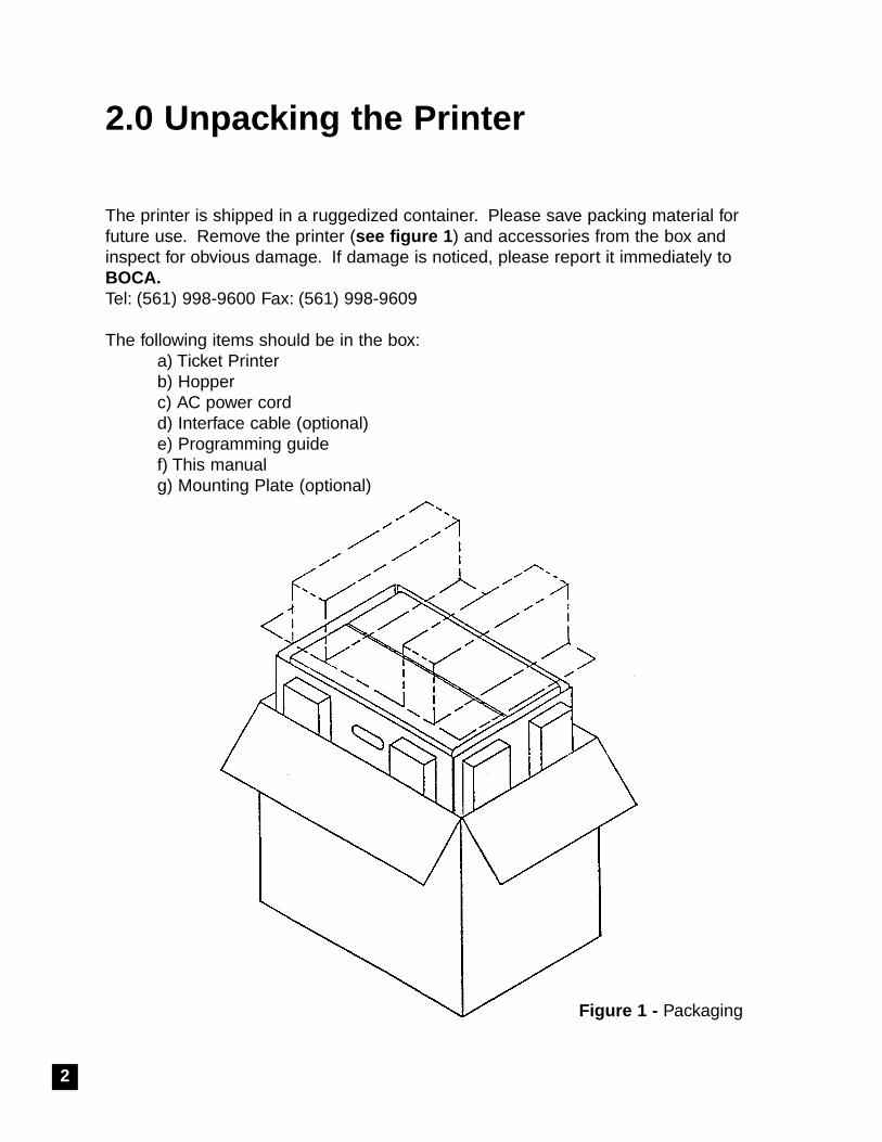
2.0 Unpac king the Printer
The printer is shipped in a ruggedized container. Please save packing material forfuture use. Remove the printer (see figure 1 ) and accessories from the box andinspect for obvious damage. If damage is noticed, please report it immediately toBOCA.Tel: (561) 998-9600 Fax: (561) 998-9609
The following items should be in the box:a) Ticket Printerb) Hopper c) AC power cord d) Interface cable (optional) e) Programming guidef) This manualg) Mounting Plate (optional)
2
Figure 1 - Packaging
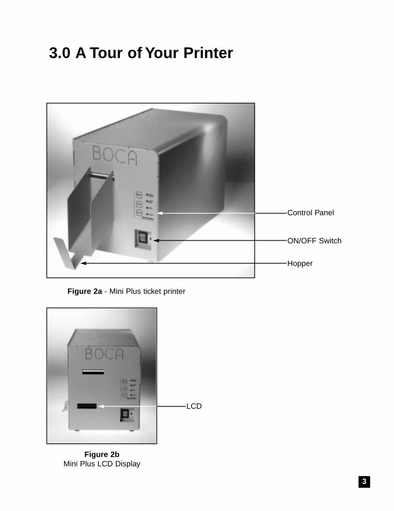
3.0 A Tour of Your Printer
Figure 2a - Mini Plus ticket printer
Hopper
Control Panel
LCD
3
ON/OFF Switch
Figure 2bMini Plus LCD Display
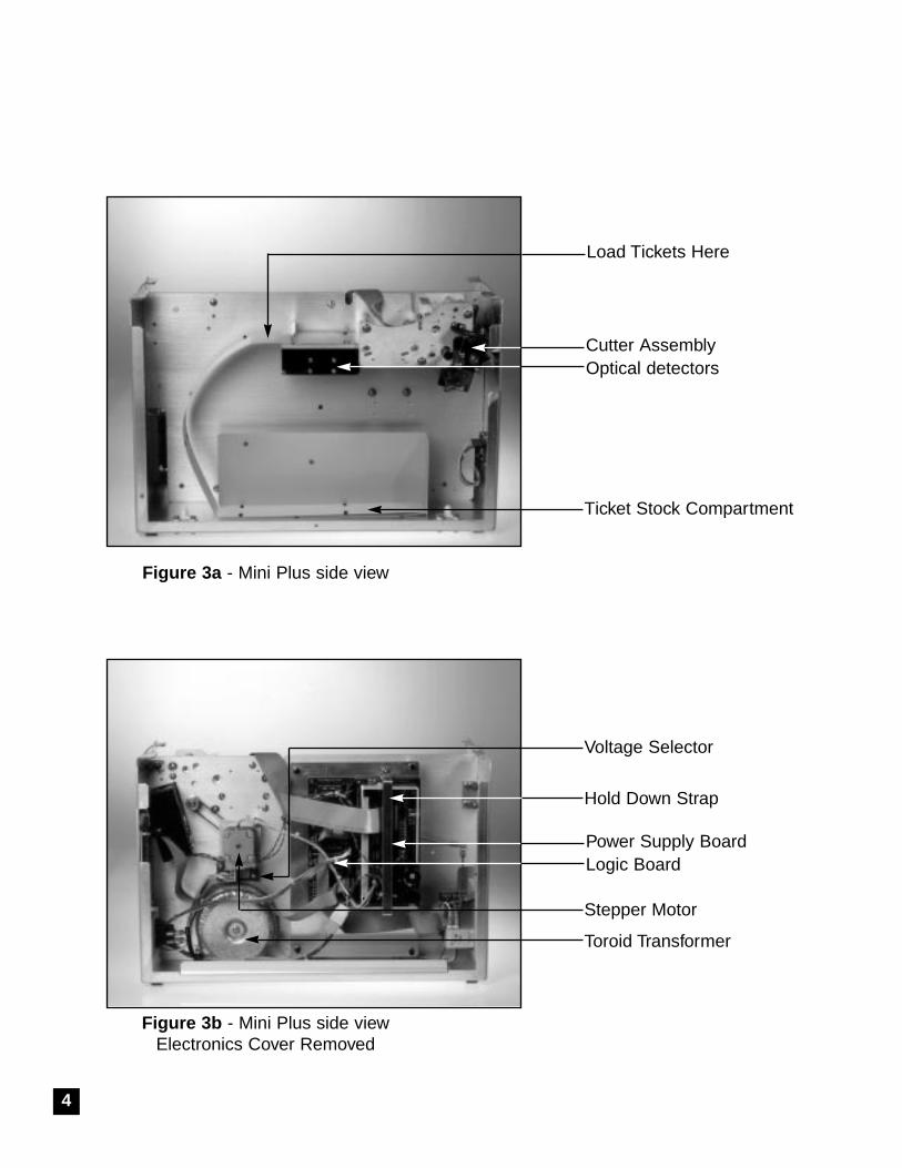
Figure 3a - Mini Plus side view
Cutter AssemblyOptical detectors
Figure 3b - Mini Plus side viewElectronics Cover Removed
Power Supply BoardLogic Board
4
Ticket Stock Compartment
Stepper Motor
Toroid Transformer
Load Tickets Here
Hold Down Strap
Voltage Selector
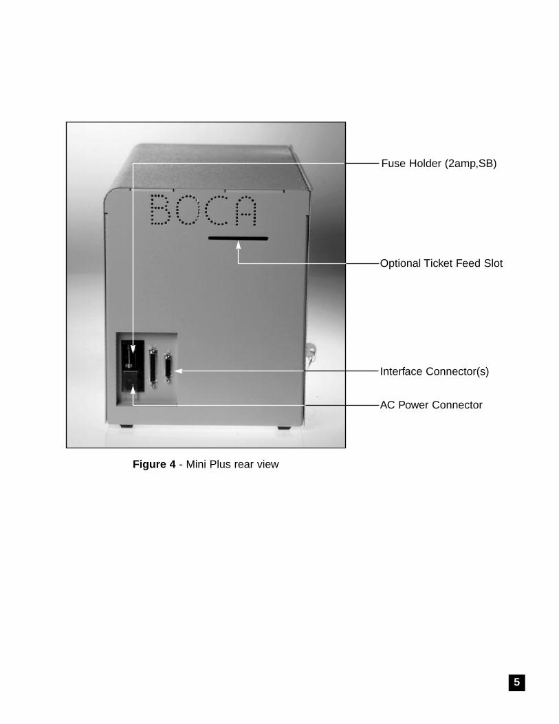
Figure 4 - Mini Plus rear view
Optional Ticket Feed Slot
Interface Connector(s)
AC Power Connector
5
Fuse Holder (2amp,SB)
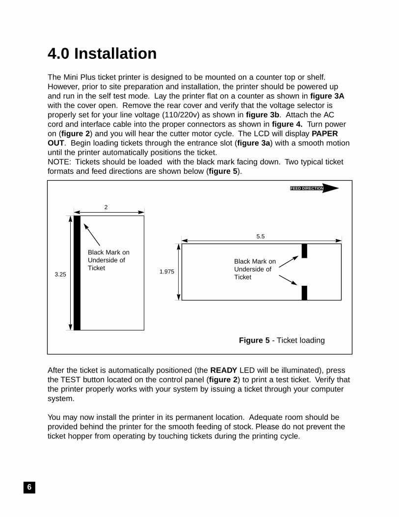
4.0 InstallationThe Mini Plus ticket printer is designed to be mounted on a counter top or shelf.However, prior to site preparation and installation, the printer should be powered upand run in the self test mode. Lay the printer flat on a counter as shown in figure 3Awith the cover open. Remove the rear cover and verify that the voltage selector isproperly set for your line voltage (110/220v) as shown in figure 3b . Attach the ACcord and interface cable into the proper connectors as shown in figure 4. Turn poweron (figure 2 ) and you will hear the cutter motor cycle. The LCD will display PAPEROUT. Begin loading tickets through the entrance slot (figure 3a ) with a smooth motionuntil the printer automatically positions the ticket.NOTE: Tickets should be loaded with the black mark facing down. Two typical ticketformats and feed directions are shown below (figure 5 ).
After the ticket is automatically positioned (the READY LED will be illuminated), pressthe TEST button located on the control panel (figure 2 ) to print a test ticket. Verify thatthe printer properly works with your system by issuing a ticket through your computersystem.
You may now install the printer in its permanent location. Adequate room should beprovided behind the printer for the smooth feeding of stock. Please do not prevent theticket hopper from operating by touching tickets during the printing cycle.
2
3.25
FEED DIRECTION
Black Mark on Underside ofTicket
5.5
1.975
Black Mark on Underside ofTicket
6
Figure 5 - Ticket loading
5.0 Configuration
The Mini Plus is factory configured for a variety of customer requirements. The printeris available in a standard FGL20 electronics package or with an enhanced FGL40package. Standard resolution is 200dpi and 300 dpi is available as an option.Please see Appendix B for the comparison of FGL 20 and 40.
The printer is available in a number of fixed ticket widths or with an optional adjustablepaper path (see figure 7). The printer is factory configured for either serial or parallelinterface (see pinouts in section 6.0 ).
A number of other features including baud rate, cut count and print speed are also fac-tory set but can be modified (Operator Menu) through the touch panel as described inAppendix A. Most users will never have reason to change the options in the OperatorMenu.
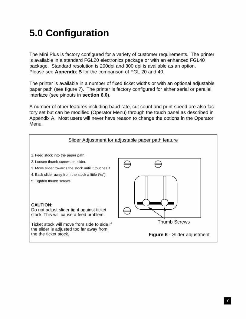
Slider Adjustment for adjustable paper path feature
1. Feed stock into the paper path.
2. Loosen thumb screws on slider.
3. Move slider towards the stock until it touches it.
4. Back slider away from the stock a little (1/32”)
5. Tighten thumb screws
CAUTION:Do not adjust slider tight against ticketstock. This will cause a feed problem.
Ticket stock will move from side to side ifthe slider is adjusted too far away fromthe the ticket stock.
Thumb Screws
Figure 6 - Slider adjustment
7
6.0 Standar d Interface Pinouts
6.1 Serial Pinouts
RS232 (Standar d) RS232 (PC type)Pin Function Pin Function2 Printer Transmit 2 Printer Receive3 Printer Receive 3 Printer Transmit7 Ground 5 RTS (+5Vdc)5,20 DTR (Printer Ready) 6 DTR (Printer Ready)4,22 RTS (+5Vdc) 7 Ground
8 CD (+5Vdc)
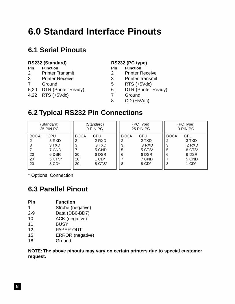
6.2 Typical RS232 Pin Connections
* Optional Connection
6.3 Parallel Pinout
Pin Function1 Strobe (negative)2-9 Data (DB0-BD7)10 ACK (negative)11 BUSY12 PAPER OUT15 ERROR (negative)18 Ground
NOTE: The abo ve pinouts ma y vary on cer tain printer s due to special customerrequest.
(Standard)25 PIN PC
BOCA CPU2 3 RXD3 3 TXD7 7 GND20 6 DSR20 5 CTS*20 8 CD*
(Standard)9 PIN PC
BOCA CPU2 2 RXD3 3 TXD7 5 GND20 6 DSR20 1 CD*20 8 CTS*
(PC Type)25 PIN PC
BOCA CPU2 2 TXD3 3 RXD5 5 CTS*6 6 DSR7 7 GND8 8 CD*
(PC Type)9 PIN PC
BOCA CPU2 3 TXD3 2 RXD5 8 CTS*6 6 DSR7 5 GND8 1 CD*
8

7.0 Thermal P aper - Theor y & SpecificationThe print head’s life expectancy is composed of both a mechanical and an electrical component. Both ofthese factors are strongly influenced by the quality of the thermal paper used.
MECHANICALThe print head has a theoretical rating of 60 kilometers. This number is based upon the assumption thatthe head will be used with a good quality, top coated thermal paper. Uncoated and poorly top coatedthermal papers are abrasive to the print head and have been found to wear through the head after lessthan one kilometer.
Other factors which may contribute to premature mechanical wear are the use of non-thermal inks andstray metallic particles stuck in ticket perforations. Certain inks colors such as opaque white (which con-tains titanium dioxide) are also highly abrasive.
Unfortunately, there are no available devices for quantitatively measuring the abrasiveness of a giventicket. Fortunately, we have developed a slightly subjective, but effective method of weeding out overlyabrasive ticket stock.
ELECTRICALEach heat element, dot, on the print head has a theoretical life expectancy of 100 million activations.This is based on the assumption that each activation will cause the dot temperature to approach thedot’s maximum recommended temperature. Running at lower temperatures will increase the theoreticallife expectancy, while slight temperature increases will seriously (exponentially) degrade the head life.
The thermal paper can affect the electrical head life in two ways. Insensitive, slow to image papers, willtypically encourage the user to increase the voltage to darken the printed image. This will directlyincrease the head temperature resulting in reduced head life. Additionally, the higher temperatures willfrequently cause the ink to peel off the ticket and deposit onto the print head. The ink debris will disruptthe normal transfer of heat from the head to the paper. This further increases the head temperatureabove the desired level. The use of non-thermal inks and/or non-top coated papers also will cause theink to release and deposit on the print head.
SPECIFICATIONBased upon the above technical information, BOCA has always tried to encourage our customers to usethe proper thermal papers to maximize the life of their print heads. BOCA provides an extensive seriesof papers which meet the above criteria for low abrasion and high sensitivity. We have also tested andapproved a number of Ricoh thermal papers which meet our criteria. While we have not had the oppor-tunity to test other manufacturers’ thermal papers, we feel confident that other papers manufactured withthe above goals in mind should be acceptable for use in our printers. The following list of papers havebeen approved by BOCA.
100 and 200 dpi usa geBOCA TLD7, TLD7R, TLD5, SF7, P8Ricoh 120TLD, 120LCSB, 120LD300 dpi usa geBOCA HS7, SFHS7Ricoh 150TLA
Please note that the 300 dpi papers may be used on 100 and 200 dpi printers. In fact, doing so willincrease the electrical life of the head as this will allow the head to operate at a lower temperature. DONOT use 300 dpi heads with 200 dpi paper.
9
8.0 Maintenance and AdjustmentsYour ticket printer is solidly constructed and has been designed for high volume use. Itrequires minimal care to provide maximum service.
This section provides an overview of printer maintenance, including part alignments,adjustment and replacement.
For discussion purposes, the printer consists of three major modules or assemblies:• Paper guide and print head assembly• Cutter assembly• Logic board assembly
As a saf ety precaution, all ser vice to the printer should be done with po wer offand the A C cor d unplug ged fr om the printer .
8.1 Paper Guide and Print Head Assemb ly
The principal function of this assembly is to guide the ticket stock to the thermal printhead where thermal printing takes place. Additionally, this assembly houses the driveplaten and optical detectors. If necessary, the total assembly can be removed from theunit. However, all replacements and adjustments of the components of this assemblycan be done without removing the total assembly. The most common adjustments andreplacements regarding this assembly follows:
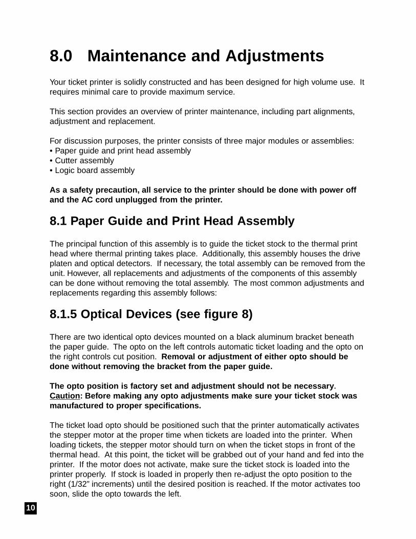
8.1.5 Optical De vices (see figure 8)
There are two identical opto devices mounted on a black aluminum bracket beneaththe paper guide. The opto on the left controls automatic ticket loading and the opto onthe right controls cut position. Removal or adjustment of either opto should bedone without remo ving the brac ket fr om the paper guide .
The opto position is factor y set and adjustment should not be necessar y.Caution : Before making an y opto adjustments make sure y our tic ket stoc k wasmanufactured to pr oper specifications.
The ticket load opto should be positioned such that the printer automatically activatesthe stepper motor at the proper time when tickets are loaded into the printer. Whenloading tickets, the stepper motor should turn on when the ticket stops in front of thethermal head. At this point, the ticket will be grabbed out of your hand and fed into theprinter. If the motor does not activate, make sure the ticket stock is loaded into theprinter properly. If stock is loaded in properly then re-adjust the opto position to theright (1/32” increments) until the desired position is reached. If the motor activates toosoon, slide the opto towards the left.
10
The printer should cut the ticket just behind the perforation. The tic ket should ne verbe cut in fr ont of the perf oration . The position of the cut can be controlled by chang-ing the cut count setting in the OPERATOR MENU (see Appendix A ). If you are notable get the desired cut position, then make sure your ticket stock was manufactured toproper specifications.
Once a year the optos eyes should be blown off with air. This interval will vary depend-ing upon the environment and the quality of the ticket stock.
FEED DIRECTION
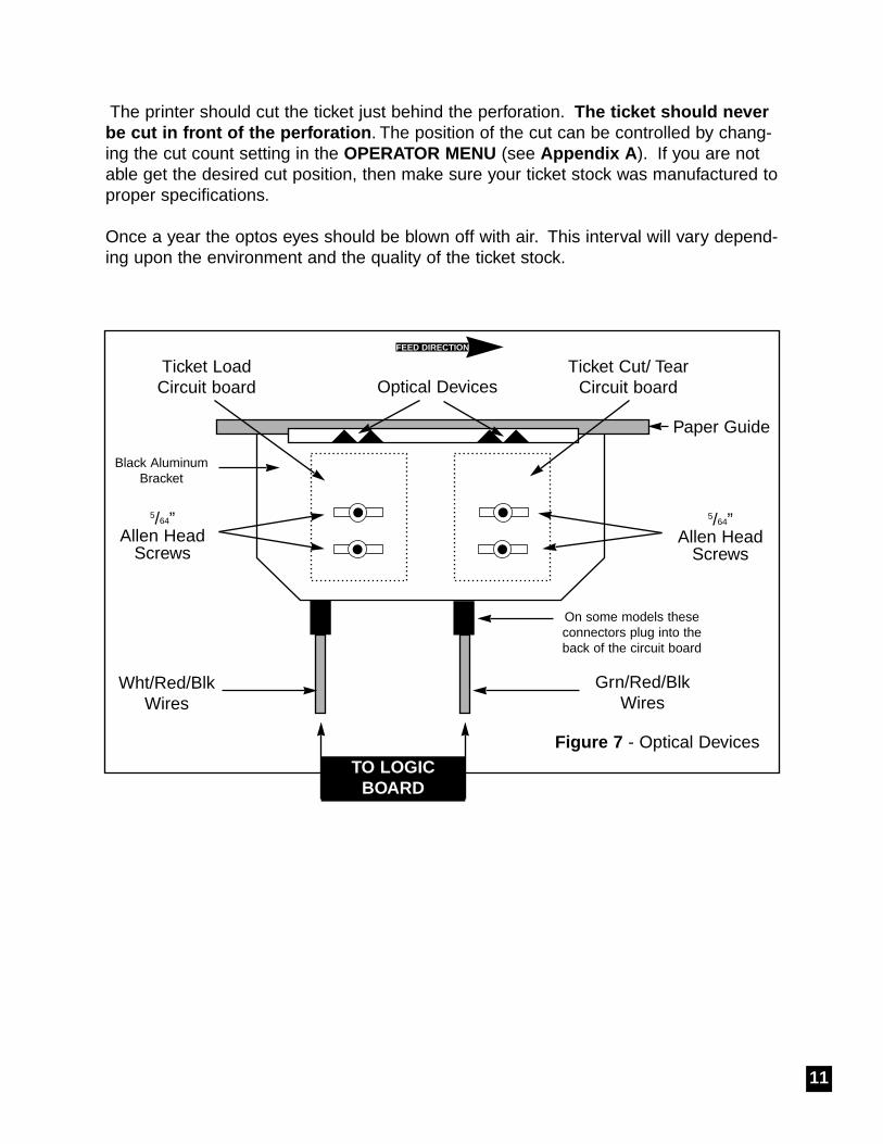
Figure 7 - Optical Devices
Optical DevicesTicket LoadCircuit board
Ticket Cut/ TearCircuit board
Paper Guide
Grn/Red/BlkWires
Wht/Red/BlkWires
5/64”Allen Head
Screws
5/64”Allen Head
Screws
On some models theseconnectors plug into theback of the circuit board
TO LOGICBOARD
Black AluminumBracket
11
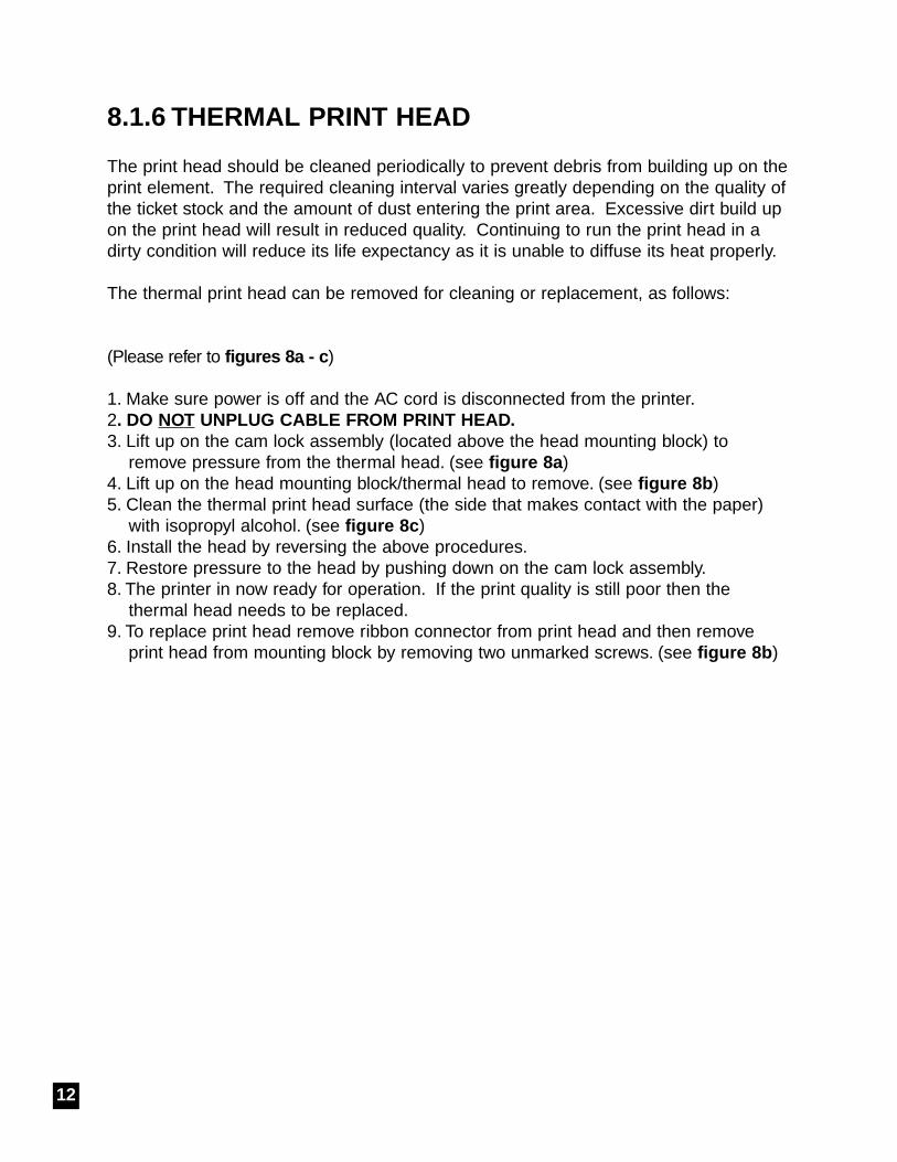
8.1.6 THERMAL PRINT HEAD
The print head should be cleaned periodically to prevent debris from building up on theprint element. The required cleaning interval varies greatly depending on the quality ofthe ticket stock and the amount of dust entering the print area. Excessive dirt build upon the print head will result in reduced quality. Continuing to run the print head in adirty condition will reduce its life expectancy as it is unable to diffuse its heat properly.
The thermal print head can be removed for cleaning or replacement, as follows:
(Please refer to figures 8a - c )
1. Make sure power is off and the AC cord is disconnected from the printer.2. DO NOT UNPLUG CABLE FR OM PRINT HEAD.3. Lift up on the cam lock assembly (located above the head mounting block) to
remove pressure from the thermal head. (see figure 8a )4. Lift up on the head mounting block/thermal head to remove. (see figure 8b )5. Clean the thermal print head surface (the side that makes contact with the paper)
with isopropyl alcohol. (see figure 8c ) 6. Install the head by reversing the above procedures.7. Restore pressure to the head by pushing down on the cam lock assembly.8. The printer in now ready for operation. If the print quality is still poor then the
thermal head needs to be replaced.9. To replace print head remove ribbon connector from print head and then remove
print head from mounting block by removing two unmarked screws. (see figure 8b )
12
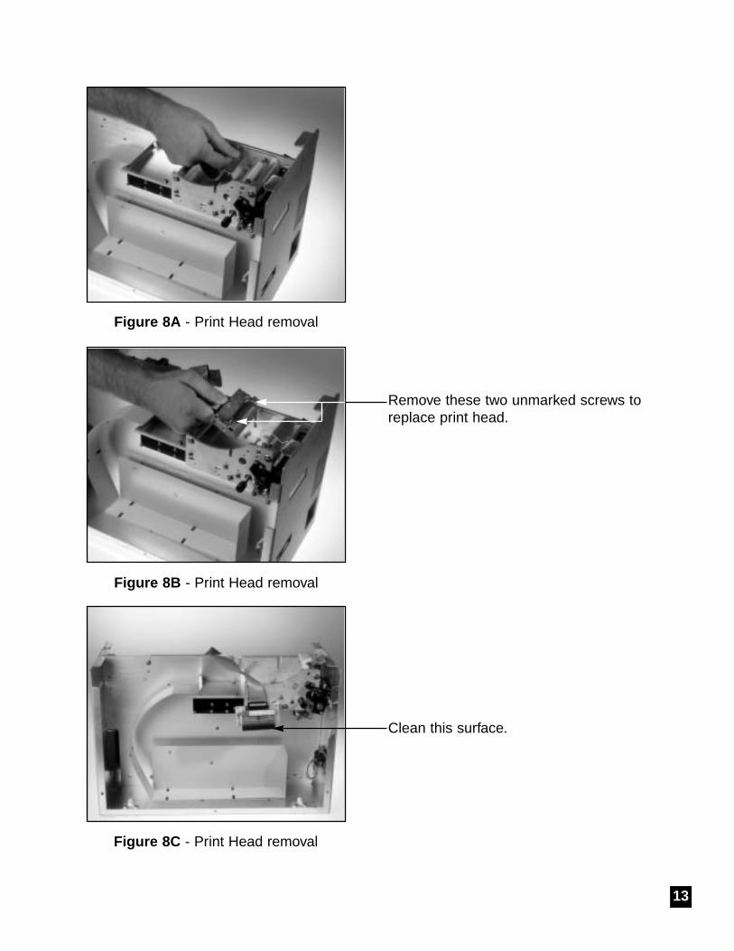
Figure 8A - Print Head removal
Figure 8B - Print Head removal
Figure 8C - Print Head removal
Clean this surface.
13
Remove these two unmarked screws toreplace print head.

8.1.7 Rubber Drive Roller (Platen)
The rubber drive roller should be cleaned once a year to prevent paper dust frombuilding up on the roller. Clean drive roller with a paper towel and alcohol.
1. Unlock the thermal head and tilt back to gain access to platen.2. Clean the full length of the platen.3. Rotate the platen clockwise and repeat step 2, continue in the same manner for
one full revolution of the platen.4. Close or lock the thermal head. Printer in now ready for normal operation.
(NOTE: The platen may require more frequent cleaning in dusty environments or when using inferior ticket stock.)
8.2 Cutter Assemb ly
The silent cutter (SC2) system is a fully integrated rotary cutter mechanism powered bya DC motor. The SC2 requires no adjustments and is rated for approximately 750,000cuts. Please be aware of the following:
Wait five seconds before feeding ticket stock into the printer after power up. During thistime the SC2 will rotate once. If ticket stock is fed into the printer before five seconds,a ticket jam could occur.
The SC2 should be blown out with air periodically to prevent debris from building upinside the cutter area. The required cleaning interval varies greatly depending on thequality of the ticket stock and the amount of paper dust entering the cutter area.
8.3 Logic Boar d and Power Suppl y Boar d
The printed circuit boards used in this product have been manufactured using surfacemount technology. These printed circuit boards cannot be effectively repaired in thefield and should be returned to the manufacturer if repair is required.
Your printer has two large printed circuit boards. The Power Supply Board plugs intothe Main Logic Board. This section describes board removal and proper installation.ALL SERVICE SHOULD BE DONE WITH POWER OFF AND THE AC CORDUNPLUGGED FROM THE PRINTER.
14
8.3a Power Suppl y Boar d (Remo val)
1. Gain access to the Logic Board Assembly by turning printer over and unscrewing electronics mounting plate.
2. Unplug connectors going to the power supply logic board.3. Unlock power supply board by pulling up and away from the 40 pin connector and
the two brass fasteners.4. Lift board and remove.
8.3b Power Suppl y Boar d (Installation)
1. Align holes on Power Supply Board with the 40 pin connector and the brass fasteners and press straight down.
2. Press down in the area of connector JCUT to properly the seat board.3. Attach connectors going to the power supply logic board.
8.3c Logic Boar d (Remo val)
1. Remove the Power Supply Board as described in section 8.3a.All connectors on the Power Supply Logic Board should stay attached.
2. Unplug connectors going to the main logic board.3. Use a screwdriver to gently wedge logic the board from the fasteners.4. Lift board and remove.
8.3d Logic Boar d (Installation)
1. Align Main Logic Board so that the four mounting holes are above the four fasteners.
2. Press logic board straight down onto the brass fasteners.3. Attach connectors going to the main logic board.4. Install Power Supply Logic Board as described is section 8.3b.
8.4 General Cleaning
The interior of the printer should be cleaned whenever this is a visible accumulation ofdust. Use a small vacuum for cleaning. Be careful not to jar any of the printer’s partsloose.
15
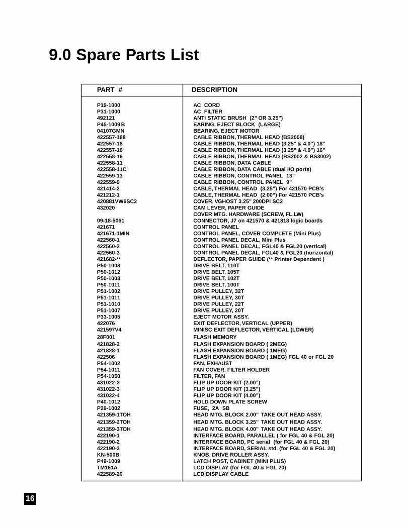
9.0 Spare Parts List
PART # DESCRIPTION
P19-1000 AC CORDP31-1000 AC FILTER492121 ANTI STATIC BRUSH (2” OR 3.25”)P45-1009 B EARING, EJECT BLOCK (LARGE)04107GMN BEARING, EJECT MOTOR422557-188 CABLE RIBBON, THERMAL HEAD (BS2008)422557-18 CABLE RIBBON, THERMAL HEAD (3.25” & 4.0”) 18”422557-16 CABLE RIBBON, THERMAL HEAD (3.25” & 4.0”) 16”422558-16 CABLE RIBBON, THERMAL HEAD (BS2002 & BS3002)422558-11 CABLE RIBBON, DATA CABLE422558-11C CABLE RIBBON, DATA CABLE (dual I/O por ts)422559-13 CABLE RIBBON, CONTROL PANEL 13”422559-9 CABLE RIBBON, CONTROL PANEL 9”421414-2 CABLE, THERMAL HEAD (3.25”) For 421570 PCB’ s421212-1 CABLE, THERMAL HEAD (2.00”) For 421570 PCB’ s420881VW6SC2 COVER, VGHOST 3.25” 200DPI SC2432020 CAM LEVER, PAPER GUIDE
COVER MTG. HARDWARE (SCREW, FL,LW)09-18-5061 CONNECTOR, J7 on 421570 & 421818 logic boar ds421671 CONTROL PANEL421671-1MIN CONTROL PANEL, COVER COMPLETE (Mini Plus)422560-1 CONTROL PANEL DECAL, Mini Plus422560-2 CONTROL PANEL DECAL, FGL40 & FGL20 (ver tical)422560-3 CONTROL PANEL DECAL, FGL40 & FGL20 (horizontal)421682-** DEFLECTOR, PAPER GUIDE (** Printer Dependent )P50-1008 DRIVE BELT, 110TP50-1012 DRIVE BELT, 105TP50-1003 DRIVE BELT, 102TP50-1011 DRIVE BELT, 100TP51-1002 DRIVE PULLEY, 32TP51-1011 DRIVE PULLEY, 30TP51-1010 DRIVE PULLEY, 22TP51-1007 DRIVE PULLEY, 20TP33-1005 EJECT MOTOR ASSY.422076 EXIT DEFLECTOR, VERTICAL (UPPER)421597V4 MINISC EXIT DEFLECTOR, VERTICAL (LOWER)28F001 FLASH MEMORY421828-2 FLASH EXPANSION BOARD ( 2MEG) 421828-1 FLASH EXPANSION BOARD ( 1MEG)422506 FLASH EXPANSION BOARD ( 1MEG) FGL 40 or FGL 20P54-1002 FAN, EXHAUSTP54-1011 FAN COVER, FILTER HOLDERP54-1050 FILTER, FAN431022-2 FLIP UP DOOR KIT (2.00”)431022-3 FLIP UP DOOR KIT (3.25”)431022-4 FLIP UP DOOR KIT (4.00”)P40-1012 HOLD DOWN PLATE SCREWP29-1002 FUSE, 2A SB421359-1TOH HEAD MTG. BLOCK 2.00” TAKE OUT HEAD ASSY.421359-2TOH HEAD MTG. BLOCK 3.25” TAKE OUT HEAD ASSY.421359-3TOH HEAD MTG. BLOCK 4.00” TAKE OUT HEAD ASSY.422190-1 INTERFACE BOARD, PARALLEL ( f or FGL 40 & FGL 20)422190-2 INTERFACE BOARD, PC serial (f or FGL 40 & FGL 20)422190-3 INTERFACE BOARD, SERIAL std. (for FGL 40 & FGL 20)KN-500B KNOB, DRIVE ROLLER ASSY.P49-1009 LATCH POST, CABINET (MINI PLUS)TM161A LCD DISPLAY (for FGL 40 & FGL 20)422589-20 LCD DISPLAY CABLE
16
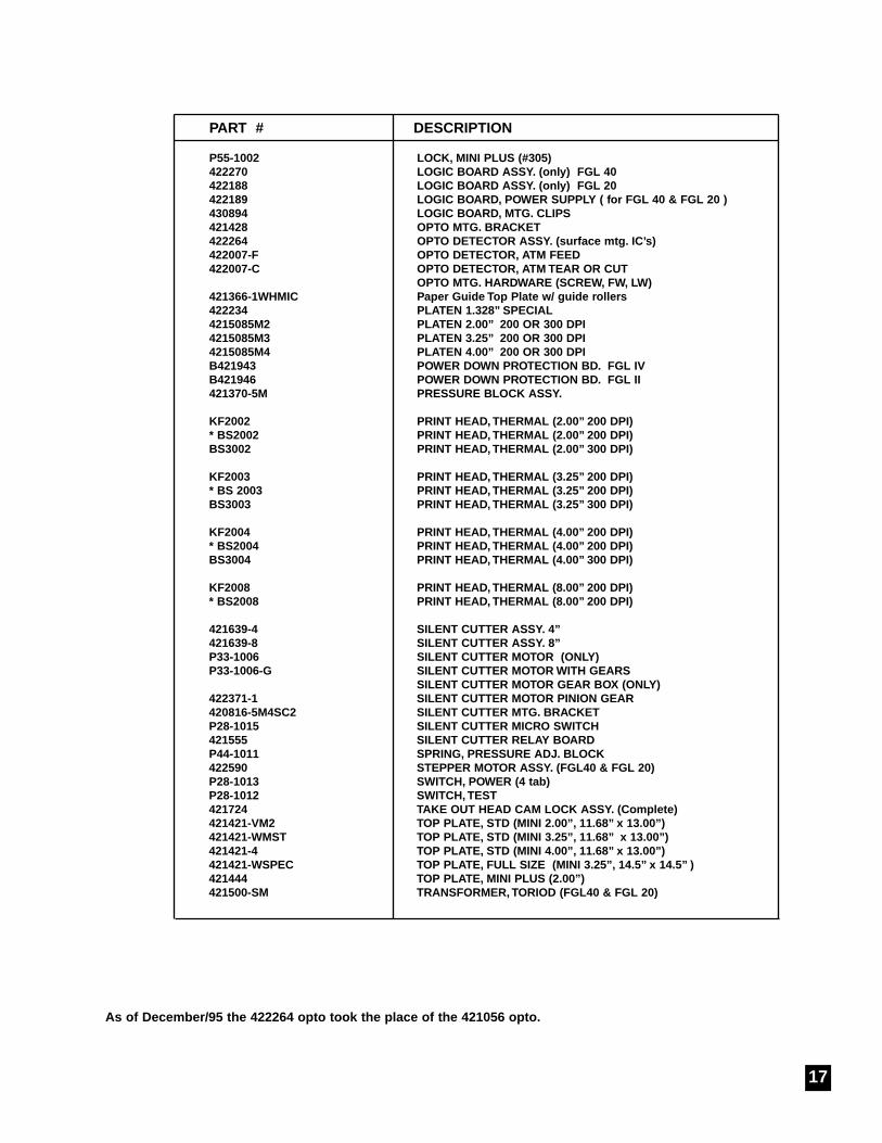
PART # DESCRIPTION
P55-1002 LOCK, MINI PLUS (#305)422270 LOGIC BOARD ASSY. (onl y) FGL 40422188 LOGIC BOARD ASSY. (onl y) FGL 20422189 LOGIC BOARD, POWER SUPPLY ( for FGL 40 & FGL 20 )430894 LOGIC BOARD, MTG. CLIPS421428 OPTO MTG. BRACKET422264 OPTO DETECTOR ASSY. (surface mtg. IC’s)422007-F OPTO DETECTOR, ATM FEED422007-C OPTO DETECTOR, ATM TEAR OR CUT
OPTO MTG. HARDWARE (SCREW, FW, LW)421366-1WHMIC Paper Guide Top Plate w/ guide r oller s422234 PLATEN 1.328” SPECIAL4215085M2 PLATEN 2.00” 200 OR 300 DPI4215085M3 PLATEN 3.25” 200 OR 300 DPI4215085M4 PLATEN 4.00” 200 OR 300 DPIB421943 POWER DOWN PROTECTION BD. FGL IVB421946 POWER DOWN PROTECTION BD. FGL II421370-5M PRESSURE BLOCK ASSY.
KF2002 PRINT HEAD, THERMAL (2.00” 200 DPI)* BS2002 PRINT HEAD, THERMAL (2.00” 200 DPI)BS3002 PRINT HEAD, THERMAL (2.00” 300 DPI)
KF2003 PRINT HEAD, THERMAL (3.25” 200 DPI)* BS 2003 PRINT HEAD, THERMAL (3.25” 200 DPI)BS3003 PRINT HEAD, THERMAL (3.25” 300 DPI)
KF2004 PRINT HEAD, THERMAL (4.00” 200 DPI)* BS2004 PRINT HEAD, THERMAL (4.00” 200 DPI)BS3004 PRINT HEAD, THERMAL (4.00” 300 DPI)
KF2008 PRINT HEAD, THERMAL (8.00” 200 DPI)* BS2008 PRINT HEAD, THERMAL (8.00” 200 DPI)
421639-4 SILENT CUTTER ASSY. 4”421639-8 SILENT CUTTER ASSY. 8”P33-1006 SILENT CUTTER MOTOR (ONLY)P33-1006-G SILENT CUTTER MOTOR WITH GEARS
SILENT CUTTER MOTOR GEAR BOX (ONLY)422371-1 SILENT CUTTER MOTOR PINION GEAR420816-5M4SC2 SILENT CUTTER MTG. BRACKETP28-1015 SILENT CUTTER MICRO SWITCH421555 SILENT CUTTER RELAY BOARDP44-1011 SPRING, PRESSURE ADJ. BLOCK422590 STEPPER MOTOR ASSY. (FGL40 & FGL 20)P28-1013 SWITCH, POWER (4 tab)P28-1012 SWITCH, TEST421724 TAKE OUT HEAD CAM LOCK ASSY . (Complete)421421-VM2 TOP PLATE, STD (MINI 2.00”, 11.68” x 13.00”)421421-WMST TOP PLATE, STD (MINI 3.25”, 11.68” x 13.00”)421421-4 TOP PLATE, STD (MINI 4.00”, 11.68” x 13.00”)421421-WSPEC TOP PLATE, FULL SIZE (MINI 3.25”, 14.5” x 14.5” )421444 TOP PLATE, MINI PLUS (2.00”)421500-SM TRANSFORMER, TORIOD (FGL40 & FGL 20)
As of December/95 the 422264 opto took the place of the 421056 opto.
17
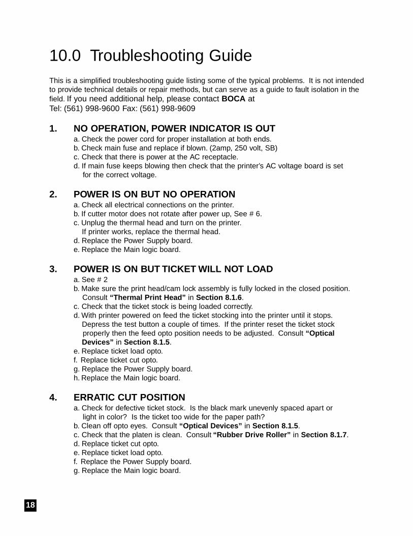
10.0 Troubleshooting Guide This is a simplified troubleshooting guide listing some of the typical problems. It is not intendedto provide technical details or repair methods, but can serve as a guide to fault isolation in thefield. If you need additional help, please contact BOCA at Tel: (561) 998-9600 Fax: (561) 998-9609
1. NO OPERATION, POWER INDICATOR IS OUTa. Check the power cord for proper installation at both ends.b. Check main fuse and replace if blown. (2amp, 250 volt, SB)c. Check that there is power at the AC receptacle.d. If main fuse keeps blowing then check that the printer’s AC voltage board is set
for the correct voltage.
2. POWER IS ON BUT NO OPERATIONa. Check all electrical connections on the printer.b. If cutter motor does not rotate after power up, See # 6.c. Unplug the thermal head and turn on the printer.
If printer works, replace the thermal head.d. Replace the Power Supply board.e. Replace the Main logic board.
3. POWER IS ON BUT TICKET WILL NOT LOADa. See # 2b. Make sure the print head/cam lock assembly is fully locked in the closed position.
Consult “Thermal Print Head” in Section 8.1.6 .c. Check that the ticket stock is being loaded correctly.d. With printer powered on feed the ticket stocking into the printer until it stops.
Depress the test button a couple of times. If the printer reset the ticket stock properly then the feed opto position needs to be adjusted. Consult “Optical Devices” in Section 8.1.5 .
e. Replace ticket load opto.f. Replace ticket cut opto.g. Replace the Power Supply board.h. Replace the Main logic board.
4. ERRATIC CUT POSITIONa. Check for defective ticket stock. Is the black mark unevenly spaced apart or
light in color? Is the ticket too wide for the paper path? b. Clean off opto eyes. Consult “Optical De vices” in Section 8.1.5 .c. Check that the platen is clean. Consult “Rubber Drive Roller” in Section 8.1.7 .d. Replace ticket cut opto.e. Replace ticket load opto.f. Replace the Power Supply board.g. Replace the Main logic board.
18
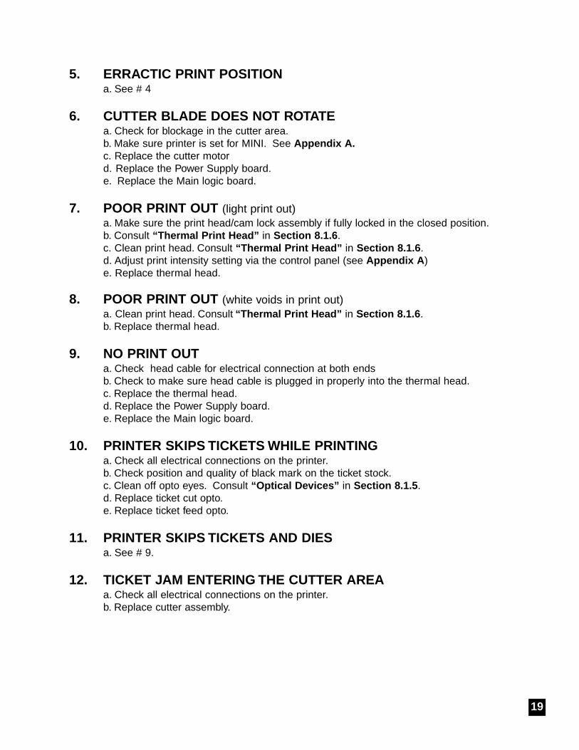
5. ERRACTIC PRINT POSITIONa. See # 4
6. CUTTER BLADE DOES NOT ROTATEa. Check for blockage in the cutter area.b. Make sure printer is set for MINI. See Appendix A.c. Replace the cutter motord. Replace the Power Supply board.e. Replace the Main logic board.
7. POOR PRINT OUT (light print out)a. Make sure the print head/cam lock assembly if fully locked in the closed position.b. Consult “Thermal Print Head” in Section 8.1.6 .c. Clean print head. Consult “Thermal Print Head” in Section 8.1.6 .d. Adjust print intensity setting via the control panel (see Appendix A )e. Replace thermal head.
8. POOR PRINT OUT (white voids in print out)a. Clean print head. Consult “Thermal Print Head” in Section 8.1.6 .b. Replace thermal head.
9. NO PRINT OUT a. Check head cable for electrical connection at both endsb. Check to make sure head cable is plugged in properly into the thermal head.c. Replace the thermal head.d. Replace the Power Supply board.e. Replace the Main logic board.
10. PRINTER SKIPS TICKETS WHILE PRINTINGa. Check all electrical connections on the printer.b. Check position and quality of black mark on the ticket stock.c. Clean off opto eyes. Consult “Optical De vices” in Section 8.1.5 .d. Replace ticket cut opto.e. Replace ticket feed opto.
11. PRINTER SKIPS TICKETS AND DIESa. See # 9.
12. TICKET JAM ENTERING THE CUTTER AREAa. Check all electrical connections on the printer.b. Replace cutter assembly.
19
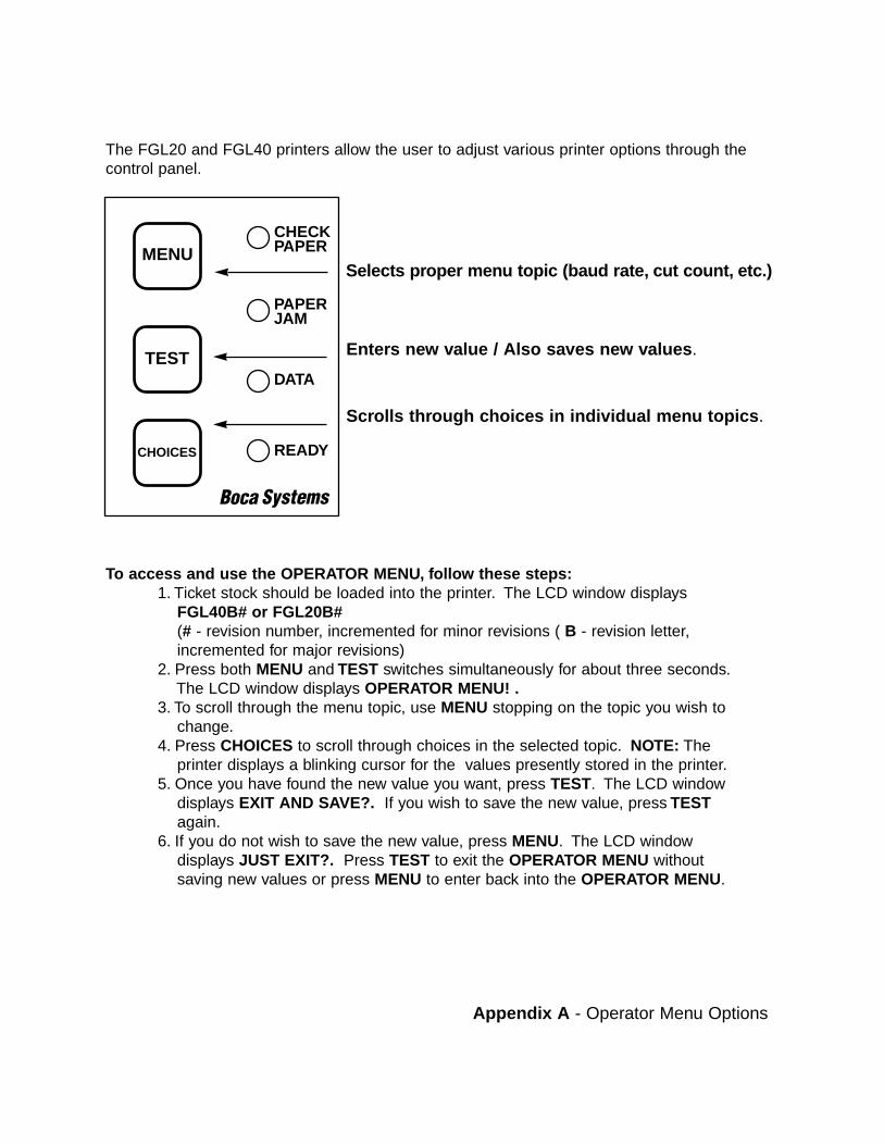
The FGL20 and FGL40 printers allow the user to adjust various printer options through thecontrol panel.
Selects pr oper men u topic (baud rate , cut count, etc.)
Enter s new value / Also sa ves ne w values .
Scrolls thr ough c hoices in individual men u topics .
To access and use the OPERA TOR MENU, follo w these steps:1. Ticket stock should be loaded into the printer. The LCD window displays
FGL40B# or FGL20B#(# - revision number, incremented for minor revisions ( B - revision letter, incremented for major revisions)
2. Press both MENU and TEST switches simultaneously for about three seconds.The LCD window displays OPERATOR MENU! .
3. To scroll through the menu topic, use MENU stopping on the topic you wish to change.
4. Press CHOICES to scroll through choices in the selected topic. NOTE: The printer displays a blinking cursor for the values presently stored in the printer.
5. Once you have found the new value you want, press TEST. The LCD window displays EXIT AND SAVE?. If you wish to save the new value, press TESTagain.
6. If you do not wish to save the new value, press MENU. The LCD window displays JUST EXIT?. Press TEST to exit the OPERATOR MENU without saving new values or press MENU to enter back into the OPERATOR MENU.
TEST
CHECKPAPER
PAPERJAM
DATA
READYCHOICES
MENU
Appendix A - Operator Menu Options
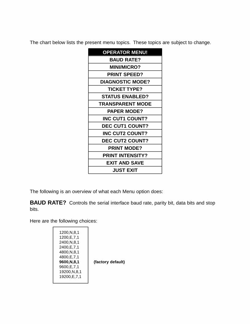
The chart below lists the present menu topics. These topics are subject to change.
OPERATOR MENU!
BAUD RATE?
MINI/MICRO?
PRINT SPEED?
DIAGNOSTIC MODE?
TICKET TYPE?
STATUS ENABLED?
TRANSPARENT MODE
PAPER MODE?
INC CUT1 COUNT?
DEC CUT1 COUNT?
INC CUT2 COUNT?
DEC CUT2 COUNT?
PRINT MODE?
PRINT INTENSITY?
EXIT AND SAVE
JUST EXIT
The following is an overview of what each Menu option does:
BAUD RATE? Controls the serial interface baud rate, parity bit, data bits and stopbits.
Here are the following choices:
1200,N,8,11200,E,7,12400,N,8,12400,E,7,14800,N,8,14800,E,7,19600,N,8,1 (factor y default)9600,E,7,119200,N,8,119200,E,7,1
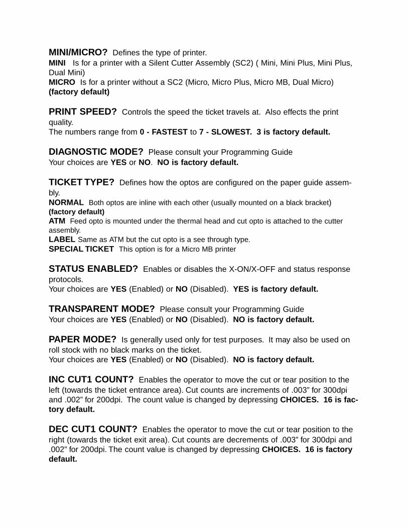
MINI/MICRO? Defines the type of printer.MINI Is for a printer with a Silent Cutter Assembly (SC2) ( Mini, Mini Plus, Mini Plus,Dual Mini)MICRO Is for a printer without a SC2 (Micro, Micro Plus, Micro MB, Dual Micro)(factor y default)
PRINT SPEED? Controls the speed the ticket travels at. Also effects the printquality.The numbers range from 0 - FASTEST to 7 - SLOWEST. 3 is factor y default.
DIAGNOSTIC MODE? Please consult your Programming GuideYour choices are YES or NO. NO is factor y default.
TICKET TYPE? Defines how the optos are configured on the paper guide assem-bly.NORMAL Both optos are inline with each other (usually mounted on a black bracket)(factor y default)ATM Feed opto is mounted under the thermal head and cut opto is attached to the cutterassembly.LABEL Same as ATM but the cut opto is a see through type.SPECIAL TICKET This option is for a Micro MB printer
STATUS ENABLED? Enables or disables the X-ON/X-OFF and status responseprotocols.Your choices are YES (Enabled) or NO (Disabled). YES is factor y default.
TRANSPARENT MODE? Please consult your Programming GuideYour choices are YES (Enabled) or NO (Disabled). NO is factor y default.
PAPER MODE? Is generally used only for test purposes. It may also be used onroll stock with no black marks on the ticket.Your choices are YES (Enabled) or NO (Disabled). NO is factor y default.
INC CUT1 COUNT? Enables the operator to move the cut or tear position to theleft (towards the ticket entrance area). Cut counts are increments of .003” for 300dpiand .002” for 200dpi. The count value is changed by depressing CHOICES. 16 is fac -tor y default.
DEC CUT1 COUNT? Enables the operator to move the cut or tear position to theright (towards the ticket exit area). Cut counts are decrements of .003” for 300dpi and.002” for 200dpi. The count value is changed by depressing CHOICES. 16 is factor ydefault.

INC CUT2 COUNT? Same as INC CUT1 COUNT? but effects path #2 on a dualpath printer.
DEC CUT2 COUNT? Same as DEC CUT1 COUNT? but effects path #2 on a dualpath printer.
PRINT MODE? Defines the automatic ticket length calculation feature.THERMAL The printer will feed out and then retract a ticket during this measurement. (facto -ry default)RIBBON The printer will feed out one blank ticket. This mode is used for label stock to pre-vent peeling.
PRINT INTENSITY? Controls the darkness of ticket print out.Here are the following choices:
LIGHTMED LIGHTNORMAL (factor y default)MED DARKSHORT HEAD LIFE
EXIT AND SAVE ! Will save any changes made to the above menu options.If you wish to save the new value then press TEST, if not press MENU.
JUST EXIT? Will exit the menu options without saving any changes.If you with to exit without saving the new value then press TEST, if not press MENU.
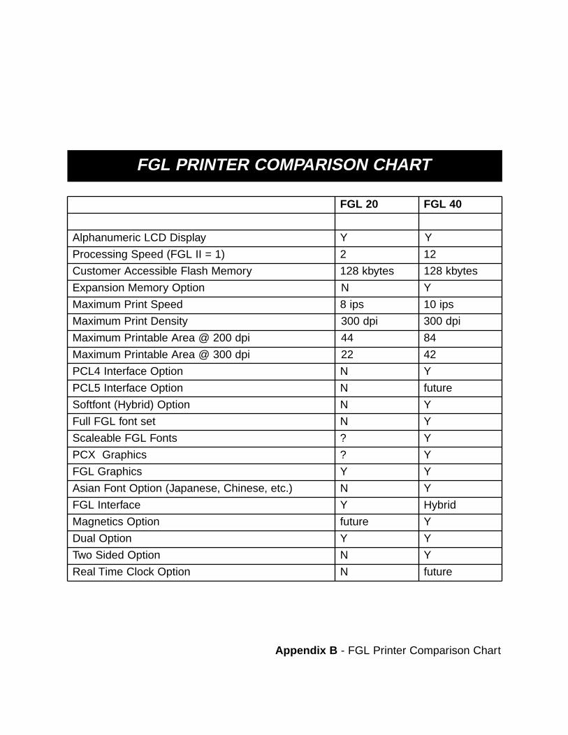
FGL PRINTER COMPARISON CHART
FGL 20 FGL 40
Alphanumeric LCD Display Y Y
Processing Speed (FGL II = 1) 2 12
Customer Accessible Flash Memory 128 kbytes 128 kbytes
Expansion Memory Option N Y
Maximum Print Speed 8 ips 10 ips
Maximum Print Density 300 dpi 300 dpi
Maximum Printable Area @ 200 dpi 44 84
Maximum Printable Area @ 300 dpi 22 42
PCL4 Interface Option N Y
PCL5 Interface Option N future
Softfont (Hybrid) Option N Y
Full FGL font set N Y
Scaleable FGL Fonts ? Y
PCX Graphics ? Y
FGL Graphics Y Y
Asian Font Option (Japanese, Chinese, etc.) N Y
FGL Interface Y Hybrid
Magnetics Option future Y
Dual Option Y Y
Two Sided Option N Y
Real Time Clock Option N future
Appendix B - FGL Printer Comparison Chart