Embed Size (px)
Citation preview

Mini Land Planer
For
Mini Skid Steer Loader And
Mini Track Loader
Operator’s Manual Set-Up Assembly
Maintenance Parts Information
Read this Manual Before Use

2
NOTE: Erskine Attachments LLC reserves the right to make improvements in design or changes in specifications at any time without notice and without incurring any obligations to install them on units previously sold.
TABLE OF CONTENTS
SAFETY 3-4
SERIAL NUMBER/DECAL LOCATION 5
MOUNTING INSTRUCTIONS 6
OPERATING INSTRUCTIONS 7-9
ROUTINE MAINTENANCE 10
SCARIFIER REMOVAL/INSTALLATION 11-12
PARTS INFORMATION 13-14
GENERAL SPECIFICATIONS 15
BOLT TORQUE INFORMATION 16
NOTES 17
WARRANTY 18
REFERENCE INFORMATION
Write the serial number for your attachment in the spaces below. Always refer to this serial
number when calling for service or parts.
Serial Number………….._____________
YOUR ATTACHMENTS DEALER
ADDRESS:
PHONE:
CONTACT:
3
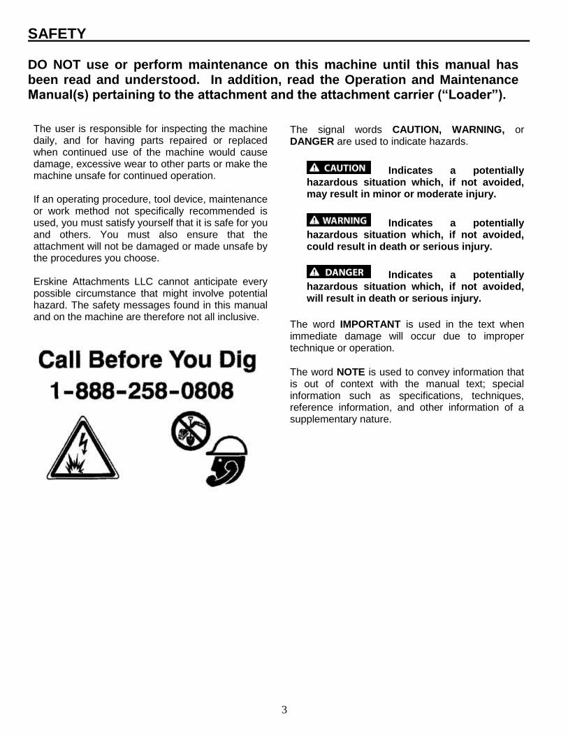
The signal words CAUTION, WARNING, or DANGER are used to indicate hazards.
Indicates a potentially hazardous situation which, if not avoided, may result in minor or moderate injury.
Indicates a potentially hazardous situation which, if not avoided, could result in death or serious injury.
Indicates a potentially hazardous situation which, if not avoided, will result in death or serious injury.
The word IMPORTANT is used in the text when
immediate damage will occur due to improper technique or operation.
The word NOTE is used to convey information that is out of context with the manual text; special information such as specifications, techniques, reference information, and other information of a supplementary nature.
The user is responsible for inspecting the machine daily, and for having parts repaired or replaced when continued use of the machine would cause damage, excessive wear to other parts or make the machine unsafe for continued operation. If an operating procedure, tool device, maintenance or work method not specifically recommended is used, you must satisfy yourself that it is safe for you and others. You must also ensure that the attachment will not be damaged or made unsafe by the procedures you choose. Erskine Attachments LLC cannot anticipate every possible circumstance that might involve potential hazard. The safety messages found in this manual and on the machine are therefore not all inclusive.
SAFETY DO NOT use or perform maintenance on this machine until this manual has been read and understood. In addition, read the Operation and Maintenance Manual(s) pertaining to the attachment and the attachment carrier (“Loader”).

4
SAFETY
Improper operation can cause serious injury or death.
Pre-operation
This attachment is designed to be used for levelling ground and hauling light material. NEVER use this
machine for any other purpose.
Read the operators manual for the “Mini Skid Steer Loader” or “Mini Track Loader”. NEVER allow
untrained people to operate.
Operating instructions must be given to everyone before operating this attachment and at least once a year thereafter in accordance with OSHA regulations.
NEVER exceed the maximum recommended input power or speed specifications for the attachment. Over-powering or over-speeding the attachment may cause personal injury and/or machine damage.
Do not modify equipment or add attachments that are not approved by Erskine Attachments LLC.
Use adequate safety warning lights and devices as required by local regulations. Obey all local laws and regulations regarding machine operation on public property. Always call before you dig (1-888-258-0808). When you call, you will be directed to a location in your state/city for information about buried lines (electric, telephone, cable TV, water, sewer, gas, etc.).
Wear Personal Protective Equipment (PPE)
Avoid loose fitting clothing. Clothing caught in moving parts may lead to serious injury or death.
Flying debris can get in eyes and lead to injury or loss of eyesight. Wear eye protection that meets ANSI z87.1 standard.
Prolonged exposure to loud noise can cause hearing impairment or hearing loss. Wear suitable hearing protection such as earmuffs or earplugs.
Operation
Check and be sure all operating controls are in neutral before starting the engine.
NEVER operate near embankments or terrain that is
so steep that rollover could occur.
Always stay in the operator position when using the attachment.
Before leaving the operators position, lower the attachment to rest flat on the ground, stop engine, set park brake.
Maintenance
NEVER make adjustments, lubricate, clean, or perform any service on the machine while it is in operation.
Make sure the attachment is serviced on a daily basis. Improper maintenance can cause serious injury or death in addition to damage to the attachment and/or your equipment.
5
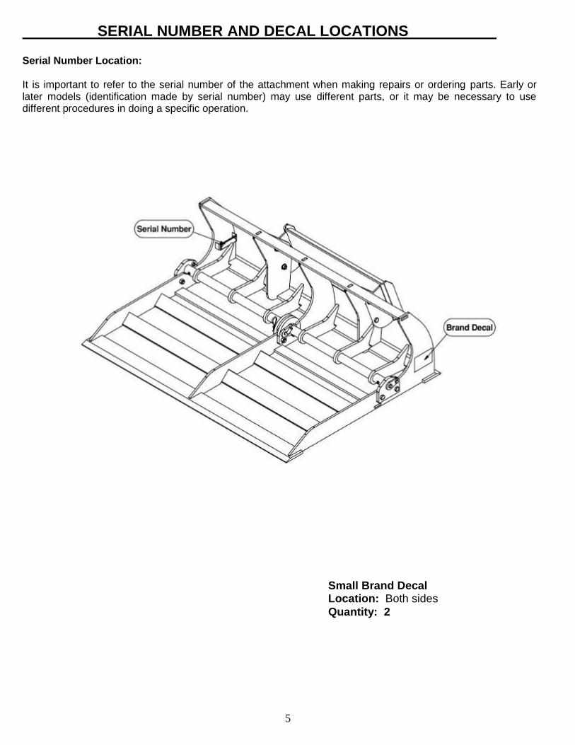
SERIAL NUMBER AND DECAL LOCATIONS
Serial Number Location: It is important to refer to the serial number of the attachment when making repairs or ordering parts. Early or later models (identification made by serial number) may use different parts, or it may be necessary to use different procedures in doing a specific operation.
Small Brand Decal Location: Both sides
Quantity: 2
6
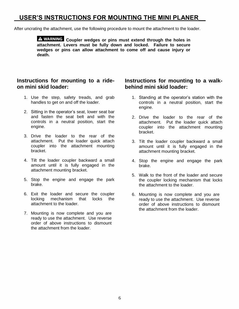
USER’S INSTRUCTIONS FOR MOUNTING THE MINI PLANER__ After uncrating the attachment, use the following procedure to mount the attachment to the loader.
Coupler wedges or pins must extend through the holes in attachment. Levers must be fully down and locked. Failure to secure wedges or pins can allow attachment to come off and cause injury or death.
Instructions for mounting to a ride-on mini skid loader:
1. Use the step, safety treads, and grab handles to get on and off the loader.
2. Sitting in the operator’s seat, lower seat bar and fasten the seat belt and with the controls in a neutral position, start the engine.
3. Drive the loader to the rear of the attachment. Put the loader quick attach coupler into the attachment mounting bracket.
4. Tilt the loader coupler backward a small amount until it is fully engaged in the attachment mounting bracket.
5. Stop the engine and engage the park brake.
6. Exit the loader and secure the coupler locking mechanism that locks the attachment to the loader.
7. Mounting is now complete and you are ready to use the attachment. Use reverse order of above instructions to dismount the attachment from the loader.
Instructions for mounting to a walk-behind mini skid loader:
1. Standing at the operator’s station with the controls in a neutral position, start the engine.
2. Drive the loader to the rear of the
attachment. Put the loader quick attach coupler into the attachment mounting bracket.
3. Tilt the loader coupler backward a small amount until it is fully engaged in the attachment mounting bracket.
4. Stop the engine and engage the park brake.
5. Walk to the front of the loader and secure the coupler locking mechanism that locks the attachment to the loader.
6. Mounting is now complete and you are ready to use the attachment. Use reverse order of above instructions to dismount the attachment from the loader.

7
Cutting the Ground
1. To cut the ground, raise the lift arms of the loader and tilt the attachment to the desired angle.
2. If operating while moving forward, lower the lift arms of the loader until the front cutting edge enters the ground.
3. If operating while moving in reverse, lower the lift arms of the loader until the rear cutting edge enters the ground.
4. Use the tilt and lift functions of the loader to increase cutting depth and traction. Keep the digging depth even in order to obtain the desired grade angle.
Always call before you dig. When you call, you will be directed to a location in your state/city for information about buried lines (electric, telephone, cable TV, water, sewer, gas, etc.).
The Mini Planer is not designed to be operated on loaders with a Rated Operating Capacity (ROC) of more than 1000 pounds.
OPERATING INSTRUCTIONS
8
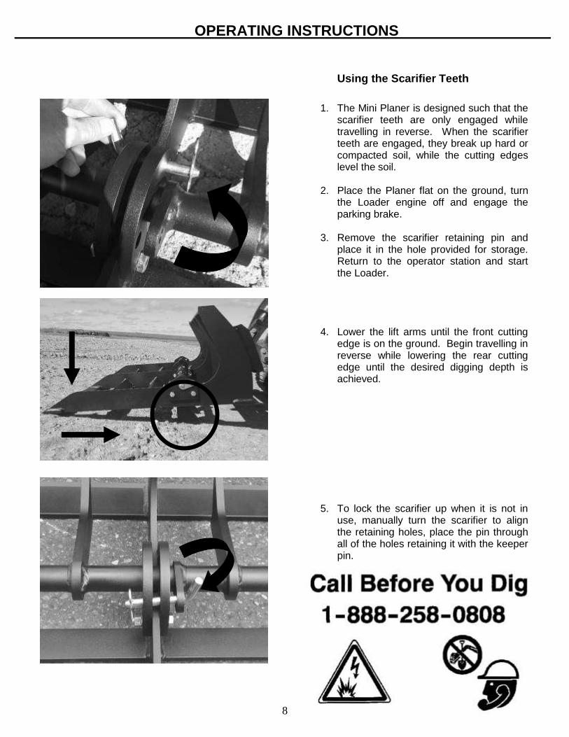
Using the Scarifier Teeth
1. The Mini Planer is designed such that the scarifier teeth are only engaged while travelling in reverse. When the scarifier teeth are engaged, they break up hard or compacted soil, while the cutting edges level the soil.
2. Place the Planer flat on the ground, turn
the Loader engine off and engage the parking brake.
3. Remove the scarifier retaining pin and
place it in the hole provided for storage. Return to the operator station and start the Loader.
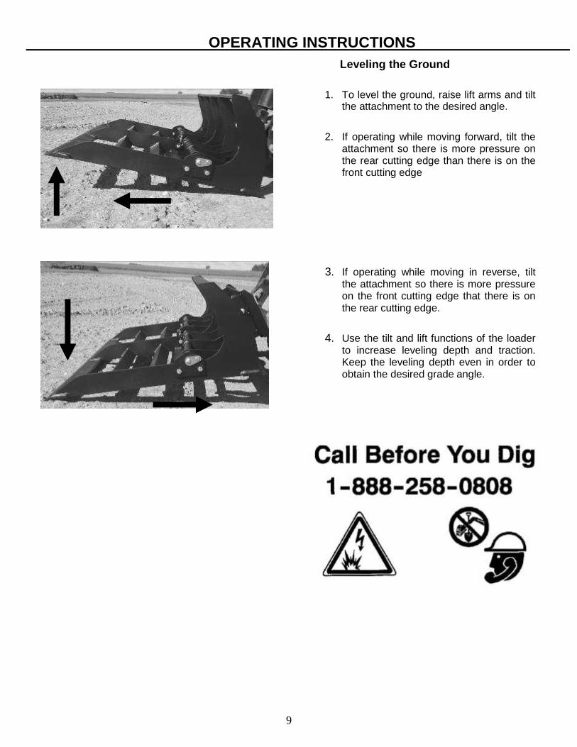
4. Lower the lift arms until the front cutting
edge is on the ground. Begin travelling in reverse while lowering the rear cutting edge until the desired digging depth is achieved.
5. To lock the scarifier up when it is not in
use, manually turn the scarifier to align the retaining holes, place the pin through all of the holes retaining it with the keeper pin.
OPERATING INSTRUCTIONS
9
Leveling the Ground
1. To level the ground, raise lift arms and tilt the attachment to the desired angle.
2. If operating while moving forward, tilt the attachment so there is more pressure on the rear cutting edge than there is on the front cutting edge
3. If operating while moving in reverse, tilt the attachment so there is more pressure on the front cutting edge that there is on the rear cutting edge.
4. Use the tilt and lift functions of the loader to increase leveling depth and traction. Keep the leveling depth even in order to obtain the desired grade angle.
OPERATING INSTRUCTIONS
10
_____________________ROUTINE MAINTENANCE________________
Lower the Mini Planer so that it rests flat on the ground, set the parking brake, shut down the engine, and remove the key before leaving the operator’s station to perform service of any kind.
It is the operator’s responsibility to make daily inspections of the loader and attachment for damage, loose bolts, fluid leaks, or anything else that could cause a potential service or safety problem. Preventive maintenance is the easiest and least expensive type of maintenance. IMPORTANT: Bolts and set screws can loosen after initial usage. After the first hour of operation check all
bolts and set screws. Continue to check for loose hardware every 10 hours of operation.
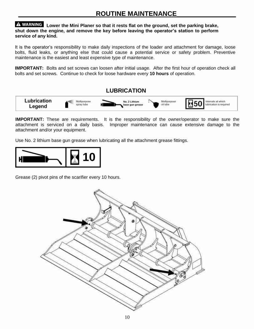
IMPORTANT: These are requirements. It is the responsibility of the owner/operator to make sure the attachment is serviced on a daily basis. Improper maintenance can cause extensive damage to the attachment and/or your equipment. Use No. 2 lithium base gun grease when lubricating all the attachment grease fittings. Grease (2) pivot pins of the scarifier every 10 hours.
10
LUBRICATION
No. 2 Lithium
base gun grease
11
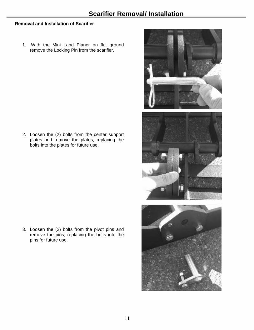
Removal and Installation of Scarifier
1. With the Mini Land Planer on flat ground
remove the Locking Pin from the scarifier.
2. Loosen the (2) bolts from the center support plates and remove the plates, replacing the bolts into the plates for future use.
3. Loosen the (2) bolts from the pivot pins and
remove the pins, replacing the bolts into the pins for future use.
Scarifier Removal/ Installation
12
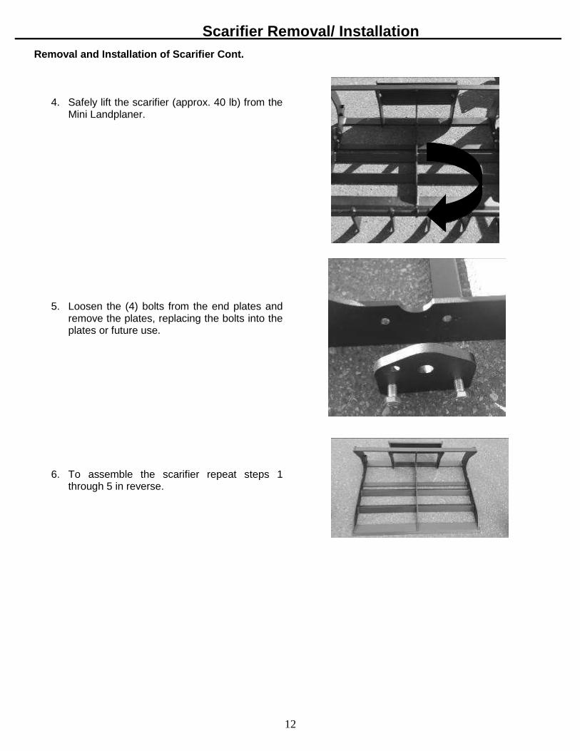
Removal and Installation of Scarifier Cont.
4. Safely lift the scarifier (approx. 40 lb) from the Mini Landplaner.
5. Loosen the (4) bolts from the end plates and
remove the plates, replacing the bolts into the plates or future use.
6. To assemble the scarifier repeat steps 1
through 5 in reverse.
Scarifier Removal/ Installation
13
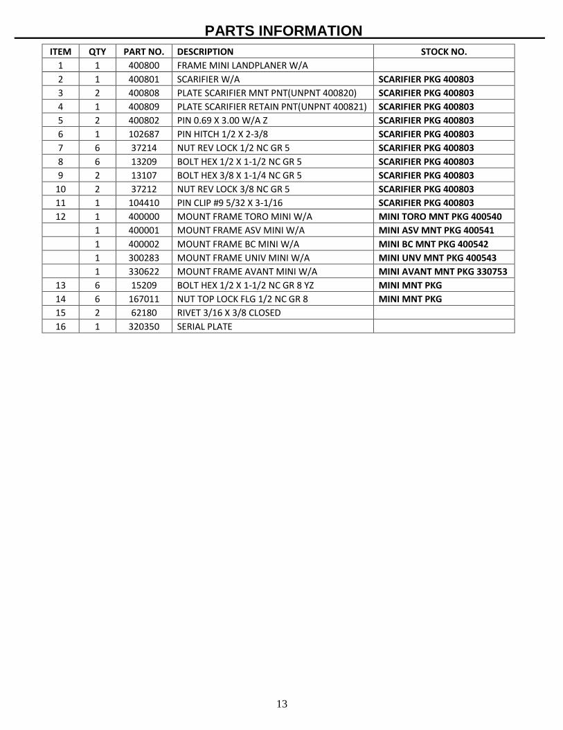
PARTS INFORMATION
ITEM QTY PART NO. DESCRIPTION STOCK NO.
1 1 400800 FRAME MINI LANDPLANER W/A
2 1 400801 SCARIFIER W/A SCARIFIER PKG 400803
3 2 400808 PLATE SCARIFIER MNT PNT(UNPNT 400820) SCARIFIER PKG 400803
4 1 400809 PLATE SCARIFIER RETAIN PNT(UNPNT 400821) SCARIFIER PKG 400803
5 2 400802 PIN 0.69 X 3.00 W/A Z SCARIFIER PKG 400803
6 1 102687 PIN HITCH 1/2 X 2-3/8 SCARIFIER PKG 400803
7 6 37214 NUT REV LOCK 1/2 NC GR 5 SCARIFIER PKG 400803
8 6 13209 BOLT HEX 1/2 X 1-1/2 NC GR 5 SCARIFIER PKG 400803
9 2 13107 BOLT HEX 3/8 X 1-1/4 NC GR 5 SCARIFIER PKG 400803
10 2 37212 NUT REV LOCK 3/8 NC GR 5 SCARIFIER PKG 400803
11 1 104410 PIN CLIP #9 5/32 X 3-1/16 SCARIFIER PKG 400803
12 1 400000 MOUNT FRAME TORO MINI W/A MINI TORO MNT PKG 400540
1 400001 MOUNT FRAME ASV MINI W/A MINI ASV MNT PKG 400541
1 400002 MOUNT FRAME BC MINI W/A MINI BC MNT PKG 400542
1 300283 MOUNT FRAME UNIV MINI W/A MINI UNV MNT PKG 400543
1 330622 MOUNT FRAME AVANT MINI W/A MINI AVANT MNT PKG 330753
13 6 15209 BOLT HEX 1/2 X 1-1/2 NC GR 8 YZ MINI MNT PKG
14 6 167011 NUT TOP LOCK FLG 1/2 NC GR 8 MINI MNT PKG
15 2 62180 RIVET 3/16 X 3/8 CLOSED
16 1 320350 SERIAL PLATE
14
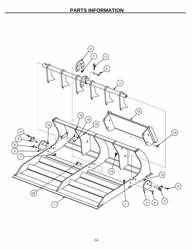
PARTS INFORMATION
15
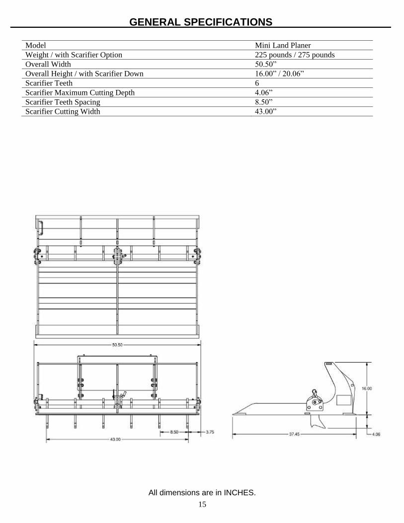
All dimensions are in INCHES.
GENERAL SPECIFICATIONS Model Mini Land Planer
Weight / with Scarifier Option 225 pounds / 275 pounds
Overall Width 50.50”
Overall Height / with Scarifier Down 16.00” / 20.06”
Scarifier Teeth 6
Scarifier Maximum Cutting Depth 4.06”
Scarifier Teeth Spacing 8.50”
Scarifier Cutting Width 43.00”

16
BOLT TORQUE INFORMATION

17
NOTES
____________________________________________________________________________________________________________________________________________________________________________________________________________________________________________________________________________________________________________________________________________________________________________________________________________________________________________________________________________________________________________________________________________________________________________________________________________________________________________________________________________________________________________________________________________________________________________________________________________________________________________________________________________________________________________________________________________________________________________________________________________________________________________________________________________________________________________________________________________________________________________________________________________________________________________________________________________________________________________________________________________________________________________________________________________________________________________________________________________________________________________________________________________________________________________________________________________________________________________________________________________________________________________________________________________________________________________________
18
LIMITED WARRANTY
Erskine Attachments, LLC warrants each new machine manufactured by us to be free from defects in material and workmanship for a period of twelve (12) months from date of delivery to the original purchaser. Our obligation under this warranty is to replace free of charge, at our factory or authorized dealership, any part proven defective within the stated warranty time limit. All parts must be returned freight prepaid and adequately packaged to prevent damage in transit. This warranty does not cover:
1. New products which have been operated in excess of rated capacities or negligence 2. Misuse, abuse, accidents or damage due to improperly routed hoses 3. Machines which have been altered, modified or repaired in any manner not
authorized by our company 4. Previously owned equipment 5. Any ground engaging tools in which natural wear is involved, i.e. tooth tips, cutting
teeth, etc 6. Normal maintenance 7. Fork tines 8. Hydraulic motors that have been disassembled in any manner
In no event will the Sales Representative, Dealership, Erskine Attachments, LLC, or any other company affiliated with it or them be liable for incidental or consequential damages or injuries, including but not limited to the loss of profit, rental or substitute equipment or other commercial loss. Purchaser’s sole and exclusive remedy being as provided here in above. Erskine Attachments, LLC must receive immediate notification of defect and no allowance will be made for repairs without our consent or approval. This warranty is in lieu of all other warranties, express or implied by law or otherwise, and there is no warranty of merchantability or fitness purpose. No agent, employee, or representative of Erskine Attachments, LLC has any authority to bind Erskine Attachments, LLC to any warranty except as specifically set forth herein. Any of these limitations excluded by local law shall be deemed deleted from this warranty; all other terms apply. This warranty may not be enlarged or modified in any manner except in writing signed by an executive officer of Erskine Attachments, LLC to improve its products whenever it is possible and practical to do so. Erskine Attachments, LLC reserves the right to make changes and or add improvements at any time without incurring any obligation to make such changes or add such improvements to products previously sold.
Erskine Attachments, LLC P.O. Box 1083 Alexandria, MN 56308
Phone (218) 435-4045

19
P/N 421999 Date Printed: 3/4/2019 Erskine Attachments LLC Printed in U.S.A.