Embed Size (px)
Citation preview

Instruction ManualMicroprocessor-Based TEACH Mode Photoelectric Sensors
U.S. patent(s) issued or pending
• TEACH-mode sensors in the popular MINI-BEAM package• Easy push-button programming automatically adjusts sensitivity to optimal
setting• Multiple sensing modes include retroreflective, polarized retro, clear object
detection, diffuse, divergent, and convergent, plus glass and plastic fiberoptic models
• Fast, 500 microsecond (0.5 millisecond) output response• Bipolar NPN (sinking)/PNP (sourcing) outputs• Easy output programming eliminates the need for Light or Dark operate
selection• Separate TEACH input allows remote programming by an external device,
such as a switch or process controller• LED status indications for received signal strength (using Banner's AID™
function), power ON, and output state• Green Stability indicator flashes when received signal level approaches the
switching threshold, also indicates Power ON• Integral 2 m (6.5 ft) cable or 5-pin Euro-style quick-disconnect (QD)
connector, depending on model; 9 m (30 ft) cable models are also available
WARNING: Not To Be Used for Personnel Protection
Never use this device as a sensing device for personnel protection. Doing so could lead toserious injury or death. This device does not include the self-checking redundant circuitry necessaryto allow its use in personnel safety applications. A sensor failure or malfunction can cause either anenergized or de-energized sensor output condition.
Models
Retroreflective Models
Model1 Sensing Mode Range or Focus2 Supply Voltage Output Type
SME312LV Retroreflective, Visible red, 650 nm 5 m (15 ft)
10 V dc to 30 V dc Bipolar NPN/PNPSME312LP Polarized retroreflective, Visible red, 650 nm 10 mm to 3 m (0.4 in to 10 ft)
SME312LPCPolarized retroreflective, Visible red, 650 nm(clear object)
1 m (3.3 ft) with supplied reflector
Diffuse Models
Model1 Sensing Mode Range or Focus Supply Voltage Output Type
SME312D Diffuse, Infrared, 880 nm 380 mm (15 in)
10 V dc to 30 V dc Bipolar NPN/PNPSME312DV Diffuse, Visible red, 650 nm 1100 mm (43 in)
SME312W Divergent Diffuse, Infrared, 880 nm 130 mm (5 in)
1 Standard 2 m (6.5 ft) cable models are listed. To order the 9 m (30 ft) cable model, add suffix “W/30” to the model number (for example,SME312LV W/30.) To order the 5-pin Euro-style QD models, add suffix “QD” (for example, SME312LVQD). Models with a QD connector require amating cable.
2 Sensing ranges vary according to the efficiency and reflective area of the retroreflector(s) used. (Retroreflective tape is not recommended for usewith Clear Object Detection models.) See Accessories and the Banner Engineering catalog for more information.
MINI-BEAM SME312 Expert Series
Original Document55214 Rev. G
13 July 2016
55214
Convergent Models
Model1 Sensing Mode Range or Focus Spot Size at Focus Supply Voltage Output Type
SME312CV Convergent, Visible red, 650 nm 16 mm (0.65 in) 1.3 mm (0.05 in)
10 V dc to 30 V dc Bipolar NPN/PNP
SME312CV2 Convergent, Visible red, 650 nm 43 mm (1.7 in) 3.0 mm (0.12 in)
SME312CVG Convergent, Visible green, 525 nm 16 mm (0.65 in) 1.0 mm (0.04 in)
SME312CVB Convergent, Visible blue, 475 nm16 mm (0.65 in) 1.8 mm (0.07 in)
SME312CVW Convergent, Visible white, 450–650 nm
Glass Fiber Optic Models
Model1 Sensing Mode Range or Focus Supply Voltage Output Type
SME312F Glass Fiber Optic, 880 nm infrared
Range varies by sensing mode andfiber optics used
10 V dc to 30 V dc Bipolar NPN/PNP
SME312FV Glass Fiber Optic, Visible red, 650 nm
SME312FVG Glass Fiber Optic, Visible green, 525 nm
SME312FVB Glass Fiber Optic, Visible blue, 475 nm
SME312FVW Glass Fiber Optic, Visible white, 450–650 nm
Plastic Fiber Optic Models
Model1 Sensing Mode Range or Focus Supply Voltage Output Type
SME312FP Plastic Fiber Optic, Visible red, 650 nm
Range varies by sensing mode andfiber optics used
10 V dc to 30 V dc Bipolar NPN/PNPSME312FPG Plastic Fiber Optic, Visible green, 525 nm
SME312FPB Plastic Fiber Optic, Visible blue, 475 nm
SME312FPW Plastic Fiber Optic, Visible white, 450–650 nm
Overview
Amber outputindicator LED
Bi-color green/redindicator LED
MINI-BEAM® Expert™ is a complete family of sensors, all housed in thepopular, robust and compact rectangular housing. Their large push buttonand easy-to-see indicators provide easy configuration, alignment, andmonitoring during use.
Retroreflective and Polarized Retroreflective Mode models are excellentfor sensing relatively small items where opposed-mode sensing is notpossible. They are recommended for relatively clean environments wherehigh excess gain is not required. Polarized models filter out unwantedreflections.
Polarized Retroreflective Mode – Clear Object Detection models reliablydetect the presence of clear objects.
Diffuse Mode models are excellent for sensing objects of adequate size and reflectivity at short range. Divergent modelsare useful for sensing small items and translucent or transparent materials at close range. The SME312DV sensorseffectively sense specular surfaces like semi-conductor wafers, disk drive media, glass and machined surfaces. Thecollimated optics of the SME312DV also permits the sensor to be mounted against clear container walls, view ports andother types of optical “feed-throughs.”
Convergent Mode models are a good choice for counting adjacent radiused objects and for accurate position sensing.Blue, green and white beam models are recommended for color mark sensing.
Glass Fiber Optic models are an excellent option for sensing in tight or otherwise inaccessible areas. Fibers withstandvibration and shock and are immune to electrical noise. Glass fibers withstand high temperatures, extreme moisture andcorrosive materials. Glass fibers are not recommended for applications requiring bending or repeated flexing (see plasticfiber models). Visible beam models are recommended for color mark sensing.
MINI-BEAM SME312 Expert Series
2 www.bannerengineering.com - Tel: +1-763-544-3164 P/N 55214 Rev. G
Plastic Fiber Optic models are an excellent option for sensing in tight or otherwise inaccessible areas. Fibers withstandvibration and shock and are immune to electrical noise. Plastic fibers function well at temperatures from –30° to +70° C (–20° F to +158° F), and stand up to repeated flexing. Most are easy to shorten in the field, for custom installations. Plasticfibers are not recommended for severe environments (see glass fiber models). Plastic fiber optic sensors are recommendedfor color mark sensing.
Status IndicatorsNormal sensor operation is called RUN mode. Sensor configuration (setting the sensitivity threshold and selecting outputON and OFF conditions) is performed in TEACH mode. The two LED indicators (bi-color green/red and amber) have distinctroles in the two operation modes. If contrast is marginal, the bi-color indicator will flash green to indicate instability. If thisoccurs, reconfigure or realign the sensor, or clean the sensor or fiber lenses.
The Signal Strength indicator is Banner’s exclusive AID™ (Alignment Indicating Device). Its pulse rate increases as thereceived light signal strength increases (during programming). This feature simplifies accurate alignment during TEACHmode, and gives a relative indication of sensing contrast between the light and dark conditions.
LED RUN Mode TEACH Mode
Solid green Power is on
Flashing green Sensed light level is approaching sensingthreshold3
Solid red Sensor “sees” its own modulated light source; pulse rate is proportional to thereceived light signal strength4
Amber on Outputs conducting Ready to TEACH output ON condition
Amber off Outputs not conducting Ready to TEACH output OFF condition
Remote ConfigurationThe remote function can be used to configure the sensor remotely or to disable the push button for security. Connect thegray wire of the sensor to ground (0 V dc), with a remote programming switch connected between them. Pulse the remoteline according to the diagrams in the configuration procedures. The length of the individual programming pulses is equal tothe value T where: 0.04 seconds ≤ “T” ≤ 0.8 seconds
Installation
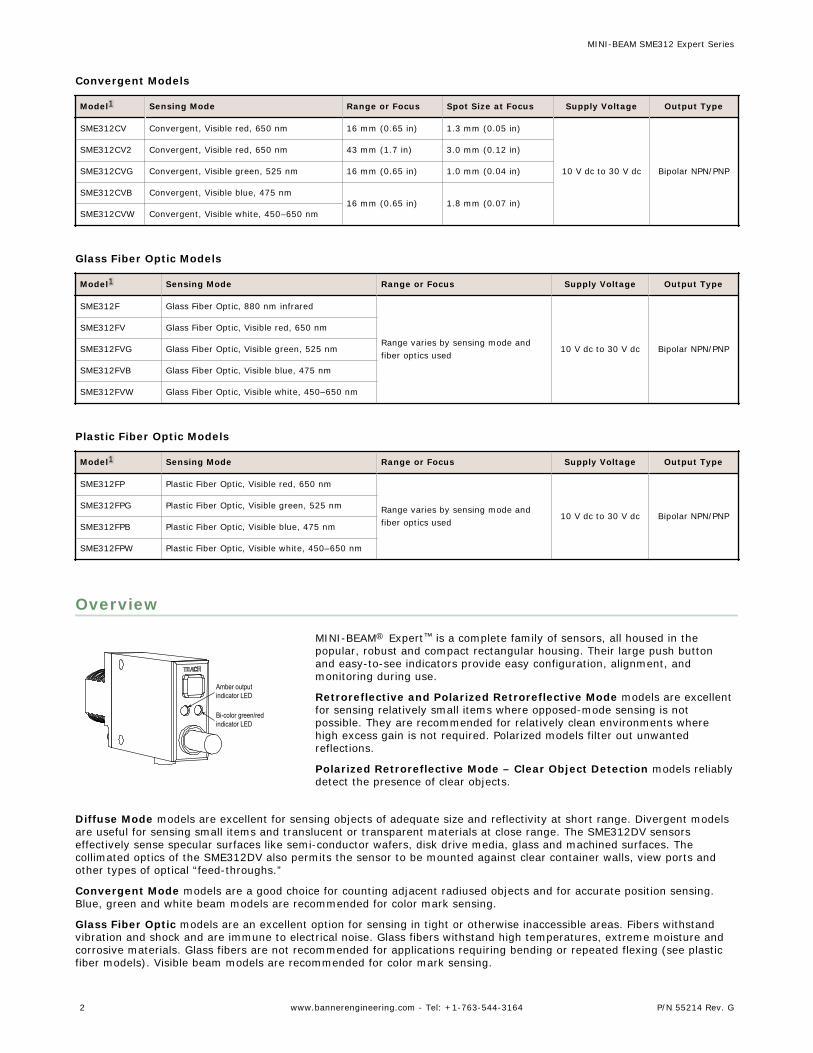
Wiring Diagrams
Cabled Models QD Models
bn
RemoteTeach
buwhbkgy
+ 10-30V dc–LoadLoad
bn
RemoteTeach
buwhbkgy
+ 10-30V dc–LoadLoad
3 This is the Stability indicator, which signals when maintenance, realignment, or reconfiguration is needed during RUN mode.4 The faster the pulse rate, the stronger the light signal.
MINI-BEAM SME312 Expert Series
P/N 55214 Rev. G www.bannerengineering.com - Tel: +1-763-544-3164 3
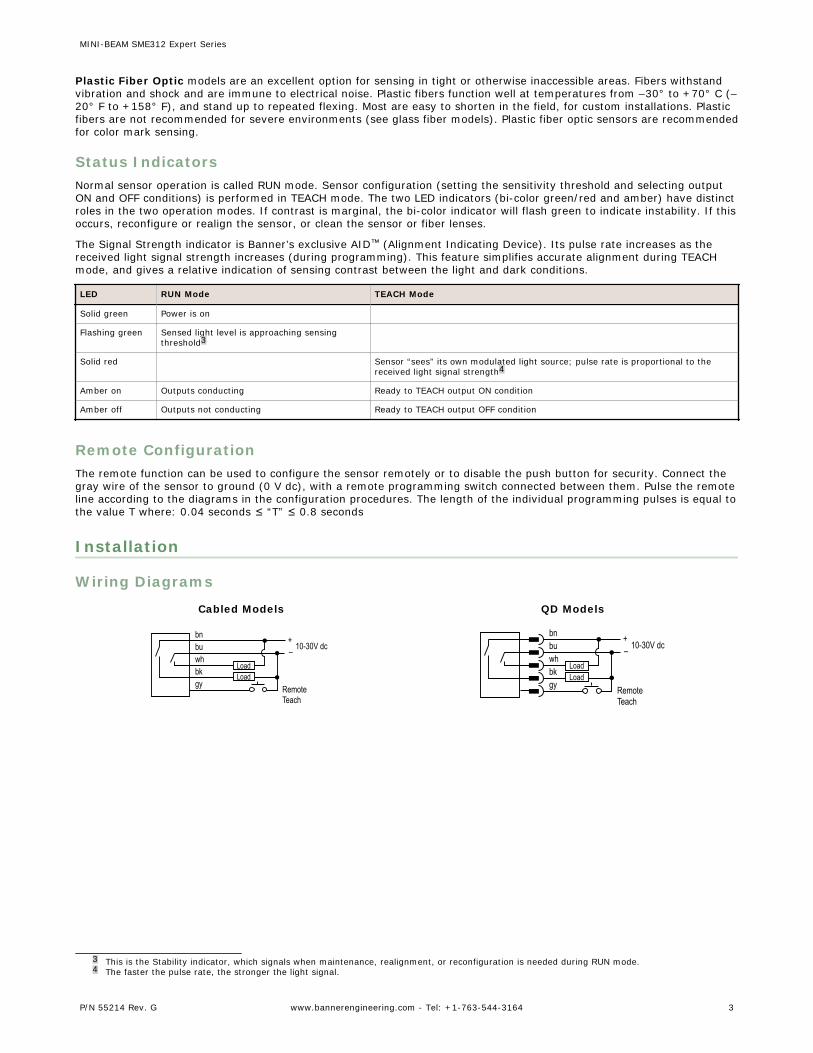
Glass Fiber Installation
O-ring
Retaining Clip
1. Install the O-ring (supplied with the fiber) on each fiber end, asshown in the drawing.
2. While pressing the fiber ends firmly into the ports on the sensorfront, slide the U-shaped retaining clip (supplied with the sensor)into the slot in the sensor's barrel, until it snaps into place.
Plastic Fiber Installation
Trimmed fibercontrol ends
Plastic fiberemitter port
Plastic fiberreceiver port
GripperUnlock
LockAdapters for0.25- and 0.5-mm fibers
Sensor Face
1. With supplied fiber cutter, make a clean cut at the controlends of fibers.
2. Unlock the fiber gripper as shown in the drawing.3. Apply appropriate fiber adaptors to the fiber, if needed.4. Gently insert the prepared fiber ends into the ports as far
as they will go.5. Slide the fiber gripper back to lock, as shown in the
drawing.
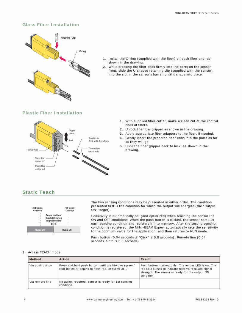
Static Teach
Sensor positions threshold between taught conditions
Output OFF Output ON
2nd TaughtCondition
1st TaughtCondition
The two sensing conditions may be presented in either order. The conditionpresented first is the condition for which the output will energize (the “OutputON” target).
Sensitivity is automatically set (and optimized) when teaching the sensor theON and OFF conditions. When the push button is clicked, the sensor sampleseach sensing condition and registers it into memory. After the second sensingcondition is registered, the MINI-BEAM Expert automatically sets the sensitivityto the optimum value for the application, and then returns to RUN mode.
Push button (0.04 seconds ≤ “Click” ≤ 0.8 seconds); Remote line (0.04seconds ≤ “T” ≤ 0.8 seconds)
1. Access TEACH mode.
Method Action Result
Via push button Press and hold push button until the bi-color (green/red) indicator begins to flash red, or turns OFF.
Push button method only: The amber LED is on. Thered LED pulses to indicate relative received signalstrength. The sensor is ready for the output ONcondition.
Via remote line No action required; sensor is ready for 1st sensingcondition.
MINI-BEAM SME312 Expert Series
4 www.bannerengineering.com - Tel: +1-763-544-3164 P/N 55214 Rev. G
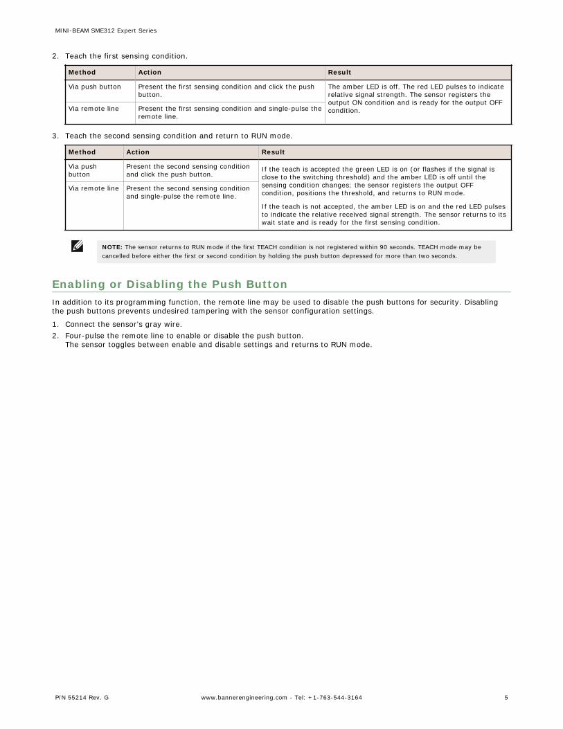
2. Teach the first sensing condition.
Method Action Result
Via push button Present the first sensing condition and click the pushbutton.
The amber LED is off. The red LED pulses to indicaterelative signal strength. The sensor registers theoutput ON condition and is ready for the output OFFcondition.Via remote line Present the first sensing condition and single-pulse the
remote line.
3. Teach the second sensing condition and return to RUN mode.
Method Action Result
Via pushbutton
Present the second sensing conditionand click the push button.
If the teach is accepted the green LED is on (or flashes if the signal isclose to the switching threshold) and the amber LED is off until thesensing condition changes; the sensor registers the output OFFcondition, positions the threshold, and returns to RUN mode.
If the teach is not accepted, the amber LED is on and the red LED pulsesto indicate the relative received signal strength. The sensor returns to itswait state and is ready for the first sensing condition.
Via remote line Present the second sensing conditionand single-pulse the remote line.
NOTE: The sensor returns to RUN mode if the first TEACH condition is not registered within 90 seconds. TEACH mode may becancelled before either the first or second condition by holding the push button depressed for more than two seconds.
Enabling or Disabling the Push ButtonIn addition to its programming function, the remote line may be used to disable the push buttons for security. Disablingthe push buttons prevents undesired tampering with the sensor configuration settings.
1. Connect the sensor’s gray wire.2. Four-pulse the remote line to enable or disable the push button.
The sensor toggles between enable and disable settings and returns to RUN mode.
MINI-BEAM SME312 Expert Series
P/N 55214 Rev. G www.bannerengineering.com - Tel: +1-763-544-3164 5
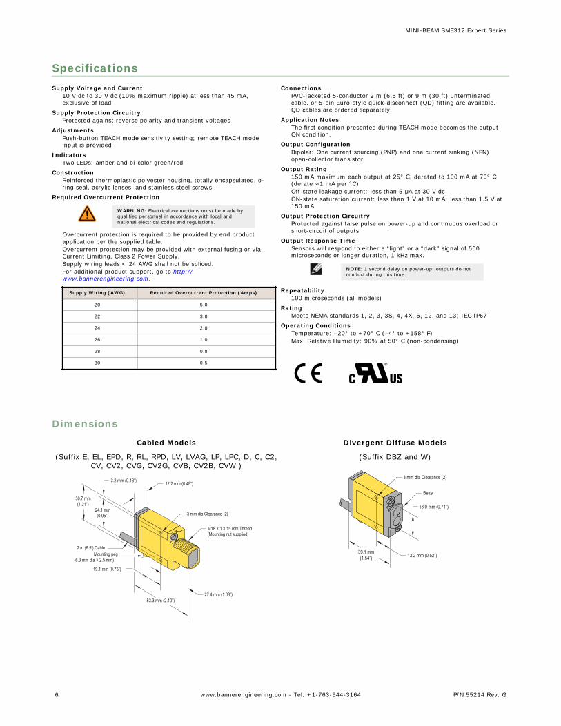
SpecificationsSupply Voltage and Current
10 V dc to 30 V dc (10% maximum ripple) at less than 45 mA,exclusive of load
Supply Protection CircuitryProtected against reverse polarity and transient voltages
AdjustmentsPush-button TEACH mode sensitivity setting; remote TEACH modeinput is provided
IndicatorsTwo LEDs: amber and bi-color green/red
ConstructionReinforced thermoplastic polyester housing, totally encapsulated, o-ring seal, acrylic lenses, and stainless steel screws.
Required Overcurrent Protection
WARNING: Electrical connections must be made byqualified personnel in accordance with local andnational electrical codes and regulations.
Overcurrent protection is required to be provided by end productapplication per the supplied table.Overcurrent protection may be provided with external fusing or viaCurrent Limiting, Class 2 Power Supply.Supply wiring leads < 24 AWG shall not be spliced.For additional product support, go to http://www.bannerengineering.com.
Supply Wiring (AWG) Required Overcurrent Protection (Amps)
20 5.0
22 3.0
24 2.0
26 1.0
28 0.8
30 0.5
ConnectionsPVC-jacketed 5-conductor 2 m (6.5 ft) or 9 m (30 ft) unterminatedcable, or 5-pin Euro-style quick-disconnect (QD) fitting are available.QD cables are ordered separately.
Application NotesThe first condition presented during TEACH mode becomes the outputON condition.
Output ConfigurationBipolar: One current sourcing (PNP) and one current sinking (NPN)open-collector transistor
Output Rating150 mA maximum each output at 25° C, derated to 100 mA at 70° C(derate ≈1 mA per °C)Off-state leakage current: less than 5 μA at 30 V dcON-state saturation current: less than 1 V at 10 mA; less than 1.5 V at150 mA
Output Protection CircuitryProtected against false pulse on power-up and continuous overload orshort-circuit of outputs
Output Response TimeSensors will respond to either a “light” or a “dark” signal of 500microseconds or longer duration, 1 kHz max.
NOTE: 1 second delay on power-up; outputs do notconduct during this time.
Repeatability100 microseconds (all models)
RatingMeets NEMA standards 1, 2, 3, 3S, 4, 4X, 6, 12, and 13; IEC IP67
Operating ConditionsTemperature: –20° to +70° C (–4° to +158° F)Max. Relative Humidity: 90% at 50° C (non-condensing)
Dimensions
Cabled Models
(Suffix E, EL, EPD, R, RL, RPD, LV, LVAG, LP, LPC, D, C, C2,CV, CV2, CVG, CV2G, CVB, CV2B, CVW )
3.2 mm (0.13”) 12.2 mm (0.48”)
3 mm dia Clearance (2)
M18 × 1 × 15 mm Thread(Mounting nut supplied)
27.4 mm (1.08”)53.3 mm (2.10”)
19.1 mm (0.75”)
Mounting peg(6.3 mm dia × 2.5 mm)
2 m (6.5’) Cable
30.7 mm(1.21”)
24.1 mm(0.95”)
Divergent Diffuse Models
(Suffix DBZ and W)
3 mm dia Clearance (2)
Bezel
18.0 mm (0.71”)
13.2 mm (0.52”)39.1 mm(1.54”)
MINI-BEAM SME312 Expert Series
6 www.bannerengineering.com - Tel: +1-763-544-3164 P/N 55214 Rev. G
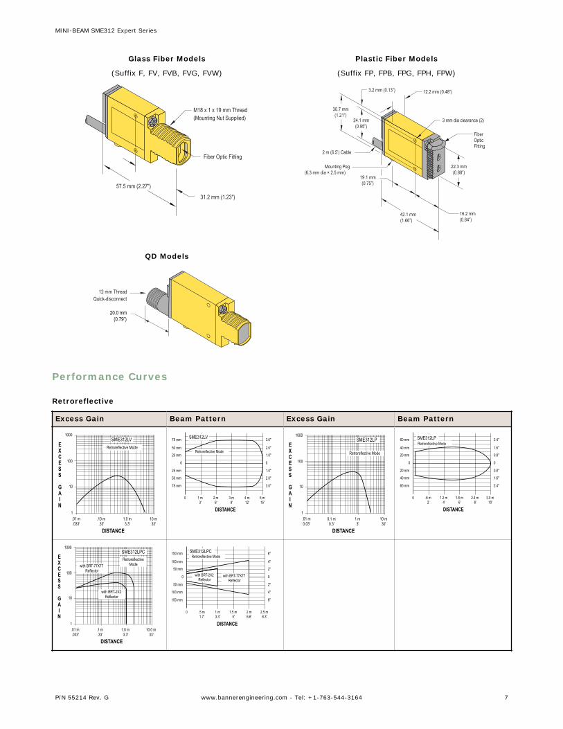
Glass Fiber Models
(Suffix F, FV, FVB, FVG, FVW)
M18 x 1 x 19 mm Thread(Mounting Nut Supplied)
57.5 mm (2.27")
31.2 mm (1.23")
Fiber Optic Fitting
Plastic Fiber Models
(Suffix FP, FPB, FPG, FPH, FPW)
3.2 mm (0.13”) 12.2 mm (0.48”)
3 mm dia clearance (2)
FiberOpticFitting
22.3 mm(0.88”)
16.2 mm(0.64”)
42.1 mm(1.66”)
19.1 mm(0.75”)
Mounting Peg(6.3 mm dia × 2.5 mm)
2 m (6.5’) Cable
30.7 mm(1.21”)
24.1 mm(0.95”)
QD Models
20.0 mm(0.79”)
12 mm ThreadQuick-disconnect
Performance Curves
Retroreflective
Excess Gain Beam Pattern Excess Gain Beam Pattern
1
10
100
1000
.10 m.33'
1.0 m3.3'
10 m33'
.01 m.033'
EXCESS
GAIN
DISTANCE
SME312LVRetroreflective Mode
5 m15'
4 m12'
3 m9'
2 m6'
1 m3'
0
0
25 mm
50 mm
75 mm
25 mm
50 mm
75 mm
0
1.0"
2.0"
3.0"
1.0"
2.0"
3.0"
DISTANCE
SME312LV
Retroreflective Mode
1
10
100
0.1 m0.3'
1 m3'
10 m30'
.01 m0.03'
1000
EXCESS
GAIN
DISTANCE
SME312LP
Retroreflective Mode
3.0 m10'
2.4 m8'
1.8 m6'
1.2 m4'
.6 m2'
0
0
20 mm
40 mm
60 mm
20 mm
40 mm
60 mm
0
0.8"
1.6"
2.4"
0.8"
1.6"
2.4"
DISTANCE
SME312LPRetroreflective Mode
1
10
100
.1 m.33'
1.0 m3.3'
10.0 m33'
.01 m.033'
1000
EXCESS
GAIN
DISTANCE
SME312LPCRetroreflective
Mode
with BRT-2X2 Reflector
with BRT-77X77Reflector
2.5 m8.3'
2 m6.6'
1.5 m5'
1 m3.3'
.5 m1.7'
0
0
50 mm
100 mm
150 mm
50 mm
100 mm
150 mm
0
2"
4"
6"
2"
4"
6"
DISTANCE
SME312LPCRetroreflective Mode
with BRT-2X2 Reflector
with BRT-77X77Reflector
MINI-BEAM SME312 Expert Series
P/N 55214 Rev. G www.bannerengineering.com - Tel: +1-763-544-3164 7
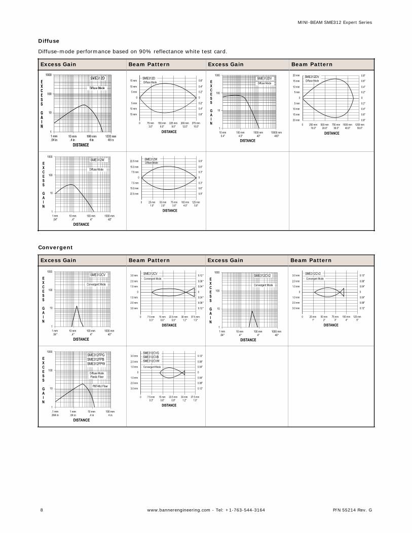
Diffuse
Diffuse-mode performance based on 90% reflectance white test card.
Excess Gain Beam Pattern Excess Gain Beam Pattern
375 mm15.0"
300 mm12.0"
225 mm9.0"
150 mm6.0"
75 mm3.0"
0
0
5 mm
10 mm
15 mm
5 mm
10 mm
15 mm
0
0.2"
0.4"
0.6"
0.2"
0.4"
0.6"
DISTANCE
SME312DDiffuse Mode
1
10
100
10 mm0.4"
100 mm4.0"
1000 mm40"
10000 mm400"
1000
EXCESS
GAIN
DISTANCE
SME312DVDiffuse Mode
1250 mm50.0"
1000 mm40.0"
750 mm30.0"
500 mm20.0"
250 mm10.0"
0
0
5 mm
10 mm
15 mm
5 mm
10 mm
15 mm
20 mm
0
0.2"
0.4"
0.6"
20 mm 0.8"
0.2"
0.4"
0.6"
0.8"
DISTANCE
SME312DVDiffuse Mode
1
10
100
10 mm.4"
100 mm4"
1000 mm40"
1 mm.04"
1000
EXCESS
GAIN
DISTANCE
SME312W
Diffuse Mode
125 mm5.0"
100 mm4.0"
75 mm3.0"
50 mm2.0"
25 mm1.0"
0
0
7.5 mm
15.0 mm
22.5 mm
7.5 mm
15.0 mm
22.5 mm
0
0.3"
0.6"
0.9"
0.3"
0.6"
0.9"
DISTANCE
SME312WDiffuse Mode
Convergent
Excess Gain Beam Pattern Excess Gain Beam Pattern
1
10
100
10 mm.4"
100 mm4"
1000 mm40"
1 mm.04"
1000
EXCESS
GAIN
DISTANCE
SME312CV
Convergent Mode
37.5 mm1.5"
30 mm1.2"
22.5 mm0.9"
15 mm0.6"
7.5 mm0.3"
0
0
1.0 mm
2.0 mm
3.0 mm
1.0 mm
2.0 mm
3.0 mm
0
0.04 "
0.08 "
0.12 "
0.04 "
0.08 "
0.12 "
DISTANCE
SME312CVConvergent Mode
1
10
100
10 mm.4"
100 mm4"
1000 mm40"
1 mm.04"
1000
EXCESS
GAIN
DISTANCE
SME312CV2
Convergent Mode
125 mm5"
100 mm4"
75 mm3"
50 mm2"
25 mm1"
0
0
1.0 mm
2.0 mm
3.0 mm
1.0 mm
2.0 mm
3.0 mm
0
0.04"
0.08"
0.12"
0.04"
0.08"
0.12"
DISTANCE
SME312CV2Convergent Mode
1
10
100
1 mm.04 in
10 mm.4 in
100 mm4 in
.1 mm.004 in
1000
EXCESS
GAIN
DISTANCE
SME312FPGSME312FPBSME312FPW
Diffuse ModePlastic Fiber
PBT46U Fiber
37.5 mm1.5"
30 mm1.2"
22.5 mm0.9"
15 mm0.6"
7.5 mm0.3"
0
0
1.0 mm
2.0 mm
3.0 mm
1.0 mm
2.0 mm
3.0 mm
0
0.04"
0.08"
0.12"
0.04"
0.08"
0.12"
DISTANCE
SME312CVGSME312CVBSME312CVWConvergent Mode
MINI-BEAM SME312 Expert Series
8 www.bannerengineering.com - Tel: +1-763-544-3164 P/N 55214 Rev. G
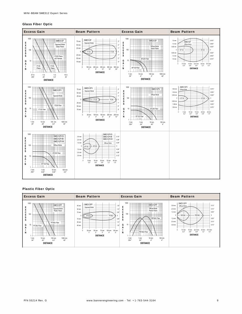
Glass Fiber Optic
Excess Gain Beam Pattern Excess Gain Beam Pattern
1
10
100
.1 m.33'
1 m3.3'
10 m33'
.01 m.033'
1000
EXCESS
GAIN
DISTANCE
SME312FOpposed Mode
Glass Fibers
IT23S Fibersw/L9 lenses
IT23S Fibers
IT13S Fibers 500 mm
20"400 mm
16"300 mm
12"200 mm
8"100 mm
4"0
0
25 mm
50 mm
75 mm
25 mm
50 mm
75 mm
0
1"
2"
3"
1"
2"
3"
DISTANCE
SME312FOpposed Mode
IT13S IT23S
1
10
100
10 mm.4"
100 mm4"
1000 mm40"
1 mm.04"
1000
EXCESS
GAIN
DISTANCE
SME312F
Diffuse ModeGlass Fibers
BT23S Fiber
BT13S Fiber
37.5 mm1.5"
30 mm1.2"
22.5 mm0.9"
15 mm0.6"
7.5 mm0.3"
0
0
0.65 mm
1.3 mm
1.9 mm
0.65 mm
1.3 mm
1.9 mm
0
0.025 "
0.050 "
0.075 "
0.025 "
0.050 "
0.075 "
DISTANCE
SME312FDiffuse Mode
BT23SBT13S
1
10
100
10 mm.40"
100 mm4.0"
1000 mm40"
1 mm.04"
1000
EXCESS
GAIN
DISTANCE
SME312FV
Opposed Mode
IT13S Fiber
IT23S Fiber
250 mm10"
200 mm8"
150 mm6"
100 mm4"
50 mm2"
0
0
25 mm
50 mm
75 mm
25 mm
50 mm
75 mm
0
1"
2"
3"
1"
2"
3"
DISTANCE
SME312FVOpposed Mode
IT13S IT23S
1
10
100
1 mm.04"
10 mm.40"
100 mm4"
.1 mm.004 "
1000
EXCESS
GAIN
DISTANCE
SME312FV
Diffuse Mode
BT23S Fiber
BT13S Fiber
25 mm1.0"
20 mm0.8"
15 mm0.6"
10 mm0.4"
5 mm0.2"
0
0
0.65 mm
1.30mm
1.95 mm
0.65 mm
1.30 mm
1.95 mm
0
0.025 "
0.050 "
0.075 "
0.025 "
0.050 "
0.075 "
DISTANCE
SME312FVDiffuse Mode
BT23SBT13S
1
10
100
1 mm0.04 "
10 mm0.40 "
100 mm4.0"
.1 mm.004 "
1000
EXCESS
GAIN
DISTANCE
SME312FVGSME312FVBSME312FVWDiffuse Mode
BT23S Fiber
BT13S Fiber
40 mm1.5"
32 mm1.2"
24 mm0.9"
16 mm0.6"
8 mm0.3"
0
0
1.0 mm
1.0 mm
0
0.04"
0.04"
2.0 mm 0.08"
3.0 mm
2.0 mm 0.08"
0.12"
3.0 mm 0.12"
DISTANCE
BT23SBT13S
SME312FVGSME312FVBSME312FVW
Diffuse Mode
Plastic Fiber Optic
Excess Gain Beam Pattern Excess Gain Beam Pattern
1
10
100
10 mm.40"
100 mm4.0"
1000 mm40"
1 mm.04"
1000
EXCESS
GAIN
DISTANCE
SME312FPOpposed ModePlastic Fibers
PIT46U FiberPIT26U Fiber
125 mm5"
100 mm4"
75 mm3"
50 mm2"
25 mm1"
0
0
15 mm
30 mm
45 mm
15 mm
30 mm
45 mm
0
0.6"
1.2"
1.8"
0.6"
1.2"
1.8"
DISTANCE
SME312FPOpposed Mode
PIT46UPIT26U
1
10
100
1 mm.04"
10 mm.4"
100 mm4"
.1 mm.004 "
1000
EXCESS
GAIN
DISTANCE
SME312FPDiffuse ModePlastic Fibers
PBT46U Fiber
PBT26U Fiber37.5 mm
1.5"30 mm
1.2"22.5 mm
0.9"15 mm
0.6"7.5 mm
0.3"0
0
1.2 mm
2.5 mm
3.8 mm
1.2 mm
2.5 mm
3.8 mm
0
0.05 "
0.10 "
0.15 "
0.05 "
0.10 "
0.15 "
DISTANCE
SME312FPDiffuse Mode
PBT46UPBT26U
MINI-BEAM SME312 Expert Series
P/N 55214 Rev. G www.bannerengineering.com - Tel: +1-763-544-3164 9
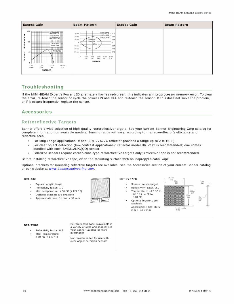
Excess Gain Beam Pattern Excess Gain Beam Pattern
1
10
100
1 mm.04 in
10 mm.4 in
100 mm4 in
.1 mm.004 in
1000
EXCESS
GAIN
DISTANCE
SME312FPGSME312FPBSME312FPW
Diffuse ModePlastic Fiber
PBT46U Fiber
20 mm0.75"
16 mm0.60"
12 mm0.45"
8 mm0.30"
4 mm0.15"
0
0
1.0 mm
2.0 mm
3.0 mm
1.0 mm
2.0 mm
3.0 mm
0
0.04"
0.08"
0.12"
0.04"
0.08"
0.12"
DISTANCE
PBT46U
SME312FPGSME312FPBSME312FPW
Diffuse ModePlastic Fiber
TroubleshootingIf the MINI-BEAM Expert’s Power LED alternately flashes red/green, this indicates a microprocessor memory error. To clearthe error, re-teach the sensor or cycle the power ON and OFF and re-teach the sensor. If this does not solve the problem,or if it occurs frequently, replace the sensor.
Accessories
Retroreflective TargetsBanner offers a wide selection of high-quality retroreflective targets. See your current Banner Engineering Corp catalog forcomplete information on available models. Sensing range will vary, according to the retroreflector’s efficiency andreflective area.
• For long-range applications: model BRT-77X77C reflector provides a range up to 2 m (6.5').• For clear object detection (low-contrast applications): reflector model BRT-2X2 is recommended; one comes
bundled with each SME312LPC(QD) sensor.• Polarized sensors require corner-cube type retroreflective targets only; reflective tape is not recommended.
Before installing retroreflective tape, clean the mounting surface with an isopropyl alcohol wipe.
Optional brackets for mounting reflective targets are available. See the Accessories section of your current Banner catalogor our website at www.bannerengineering.com.
BRT-2X2
• Square, acrylic target• Reflectivity factor: 1.0• Max. temperature: +50 °C (+122 ºF)• Optional brackets are available• Approximate size: 51 mm × 51 mm
BRT-77X77C
• Square, acrylic target• Reflectivity Factor: 2.0• Temperature: −20 °C to
+60 °C (−4 °F to+140 °F)
• Optional brackets areavailable
• Approximate size: 84.5mm × 84.5 mm
84.5 mm(3.3")
77 mm(3.0")
77 mm(3.0")
3.5 mm(0.13")
84.5 mm(3.3")
9 mm(0.4")
ClearAcrylicLens
BRT-TVHG
• Reflectivity factor: 0.8• Max. Temperature:
+60 °C (+140 °F)
Retroreflective tape is available ina variety of sizes and shapes; seeyour Banner Catalog for moreinformation.
Not recommended for use withclear object detection sensors.
MINI-BEAM SME312 Expert Series
10 www.bannerengineering.com - Tel: +1-763-544-3164 P/N 55214 Rev. G
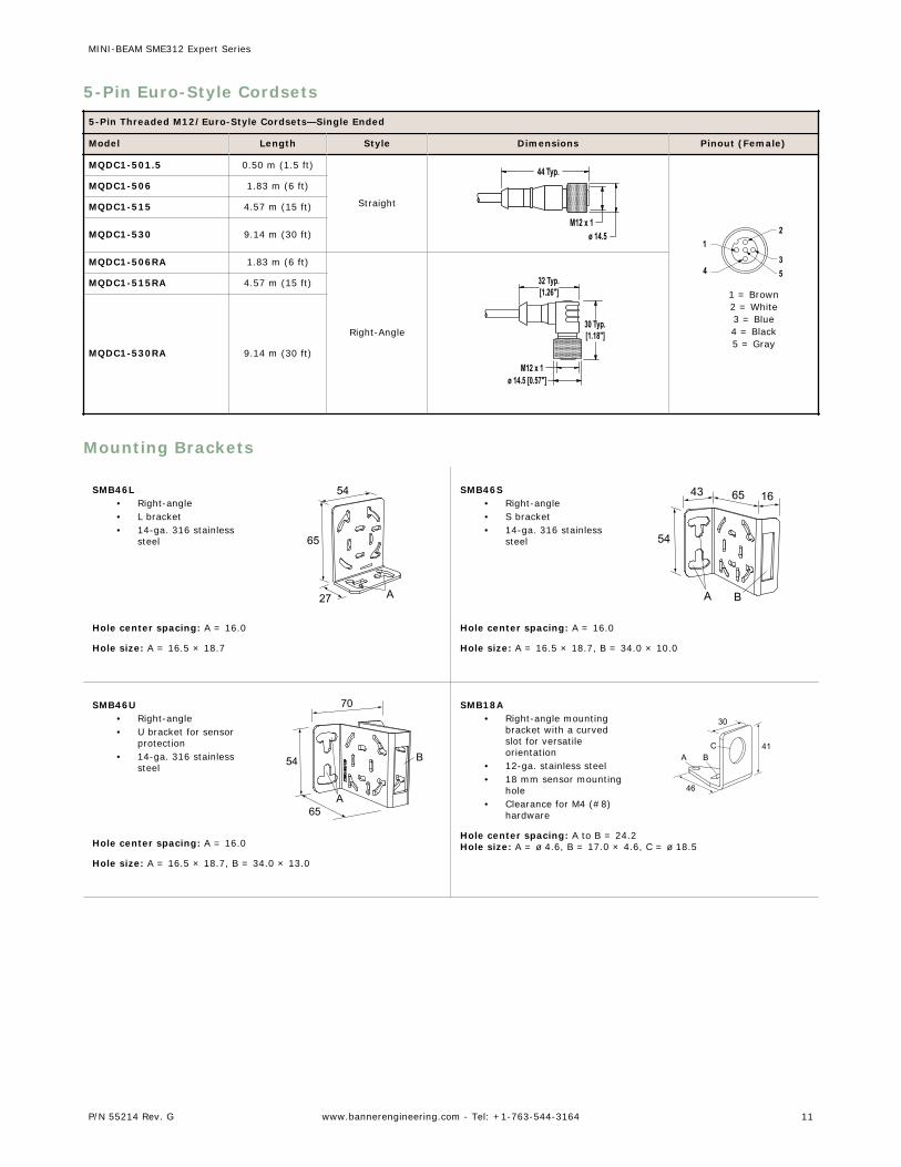
5-Pin Euro-Style Cordsets5-Pin Threaded M12/Euro-Style Cordsets—Single Ended
Model Length Style Dimensions Pinout (Female)
MQDC1-501.5 0.50 m (1.5 ft)
Straight
44 Typ.
ø 14.5M12 x 1
2
34
1
5
1 = Brown2 = White3 = Blue4 = Black5 = Gray
MQDC1-506 1.83 m (6 ft)
MQDC1-515 4.57 m (15 ft)
MQDC1-530 9.14 m (30 ft)
MQDC1-506RA 1.83 m (6 ft)
Right-Angle
32 Typ.[1.26"]
30 Typ.[1.18"]
ø 14.5 [0.57"]M12 x 1
MQDC1-515RA 4.57 m (15 ft)
MQDC1-530RA 9.14 m (30 ft)
Mounting Brackets
SMB46L• Right-angle• L bracket• 14-ga. 316 stainless
steel 65
54
27 A
Hole center spacing: A = 16.0
Hole size: A = 16.5 × 18.7
SMB46S• Right-angle• S bracket• 14-ga. 316 stainless
steel 54
43 65 16
A B
Hole center spacing: A = 16.0
Hole size: A = 16.5 × 18.7, B = 34.0 × 10.0
SMB46U• Right-angle• U bracket for sensor
protection• 14-ga. 316 stainless
steel
70
54
65
16
A
B
Hole center spacing: A = 16.0
Hole size: A = 16.5 × 18.7, B = 34.0 × 13.0
SMB18A• Right-angle mounting
bracket with a curvedslot for versatileorientation
• 12-ga. stainless steel• 18 mm sensor mounting
hole• Clearance for M4 (#8)
hardware
30
41
46
A BC
Hole center spacing: A to B = 24.2Hole size: A = ø 4.6, B = 17.0 × 4.6, C = ø 18.5
MINI-BEAM SME312 Expert Series
P/N 55214 Rev. G www.bannerengineering.com - Tel: +1-763-544-3164 11

SMB18AFA..• Protective, swivel
bracket with tilt and panmovement for precisionadjustment
• Easy sensor mounting toextruded rail T-slots
• Metric and inch size boltsavailable
• Mounting hole for 18 mmsensors
51
51
44
3/8-16 UNC
X 2 in.ø19.8
ø18.1
Hole size: B = ø 18.1
Model Bolt Thread (A)
SMB18AFA 3/8 - 16 × 2 in
SMB18AFAM10 M10 - 1.5 × 50
SMB18Q• Right-angle flanged
bracket• 18 mm sensor mounting
hole• 12-ga. stainless steel 41
46A
B
30C
Hole center spacing: A to B = 24.2Hole size: A = ø 4.6, B = 17.0 × 4.6, C = ø 19.0
SMB18SF• 18 mm swivel bracket with
M18 × 1 internal thread• Black thermoplastic
polyester• Stainless steel swivel
locking hardware included
B
A
51
42
25
Hole center spacing: A = 36.0Hole size: A = ø 5.3, B = ø 18.0
SMB18UR• 2-piece universal swivel
bracket• 300 series stainless steel• Stainless steel swivel
locking hardwareincluded
• Mounting hole for 18 mmsensor
137
64 42
B
A
C
Hole center spacing: A = 25.4, B = 46.7Hole size: B = 6.9 × 32.0, C = ø 18.3
SMB312PD• Right-angle mounting
bracket with a curvedslot for versatileorientation
• 12-ga. stainless steel• 18 mm sensor mounting
hole• Clearance for M4 (#8)
hardware
46
41B
C
A
32
Hole center spacing: A to B = 24.2Hole size: A = ø 4.6, B = 17 × 4.6, C = ø 18.5
NOTE: Not for use with plastic fiber opticsensors
SMBAMS18RA• Right-angle SMBAMS
series bracket with 18mm hole
• Articulation slots for 90+° rotation
• 12-ga. (2.6 mm) cold-rolled steel
48
45
40
AB
C
Hole center spacing: A = 26.0, A to B = 13.0Hole size: A = 26.8 × 7.0, B = ø 6.5, C = ø 19.0
SMBAMS18P• Flat SMBAMS series
bracket with 18 mm hole• Articulation slots for 90+
° rotation• 12-ga. (2.6 mm) cold-
rolled steel
45
78
A
B
C
Hole center spacing: A = 26.0, A to B = 13.0Hole size: A = 26.8 × 7.0, B = ø 6.5, C = ø 19.0
SMB30SK• Flat-mount swivel bracket
with extended range ofmotion
• Black reinforcedthermoplastic polyester and316 stainless steel
• Stainless steel swivel lockinghardware included
68
57
78
A
B
Hole center spacing: A = 50.8Hole size: A = ø 7, B = ø 18
MINI-BEAM SME312 Expert Series
12 www.bannerengineering.com - Tel: +1-763-544-3164 P/N 55214 Rev. G
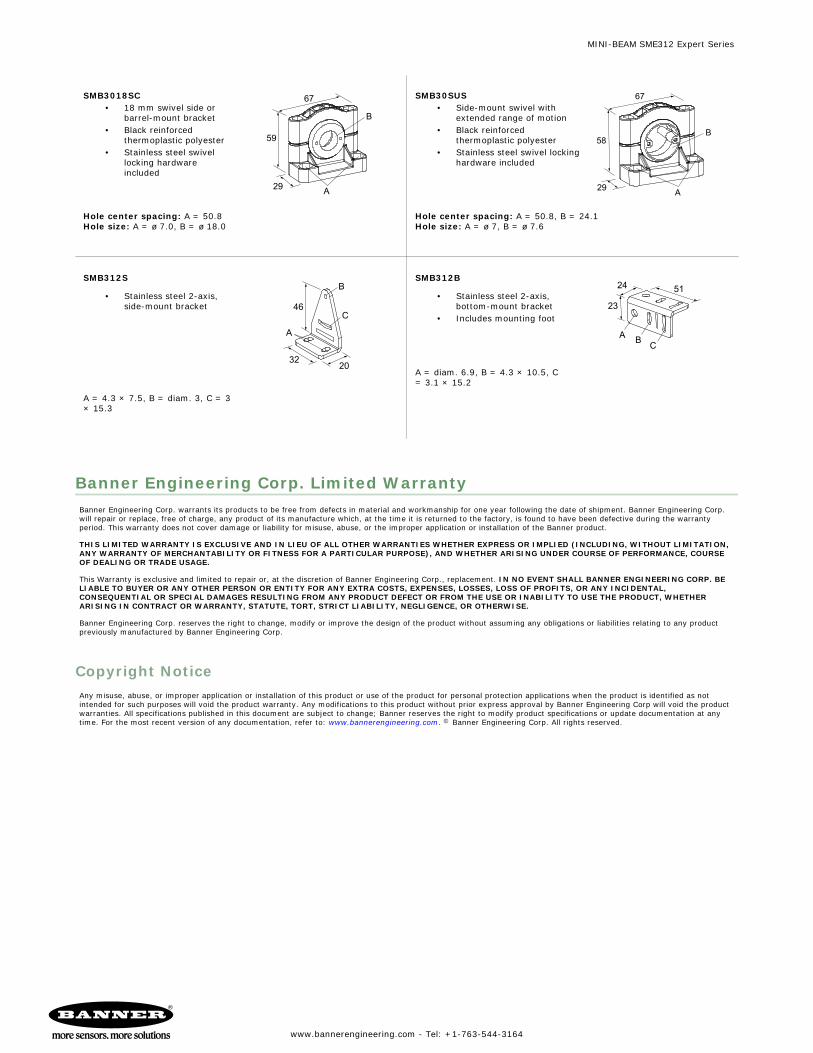
SMB3018SC• 18 mm swivel side or
barrel-mount bracket• Black reinforced
thermoplastic polyester• Stainless steel swivel
locking hardwareincluded
B
A
67
59
29
Hole center spacing: A = 50.8Hole size: A = ø 7.0, B = ø 18.0
SMB30SUS• Side-mount swivel with
extended range of motion• Black reinforced
thermoplastic polyester• Stainless steel swivel locking
hardware included
A
67
58
29
B
Hole center spacing: A = 50.8, B = 24.1Hole size: A = ø 7, B = ø 7.6
SMB312S
• Stainless steel 2-axis,side-mount bracket 46
B
C
A
3220
A = 4.3 × 7.5, B = diam. 3, C = 3× 15.3
SMB312B
• Stainless steel 2-axis,bottom-mount bracket
• Includes mounting foot
5124
23
B CA
A = diam. 6.9, B = 4.3 × 10.5, C= 3.1 × 15.2
Banner Engineering Corp. Limited WarrantyBanner Engineering Corp. warrants its products to be free from defects in material and workmanship for one year following the date of shipment. Banner Engineering Corp.will repair or replace, free of charge, any product of its manufacture which, at the time it is returned to the factory, is found to have been defective during the warrantyperiod. This warranty does not cover damage or liability for misuse, abuse, or the improper application or installation of the Banner product.
THIS LIMITED WARRANTY IS EXCLUSIVE AND IN LIEU OF ALL OTHER WARRANTIES WHETHER EXPRESS OR IMPLIED (INCLUDING, WITHOUT LIMITATION,ANY WARRANTY OF MERCHANTABILITY OR FITNESS FOR A PARTICULAR PURPOSE), AND WHETHER ARISING UNDER COURSE OF PERFORMANCE, COURSEOF DEALING OR TRADE USAGE.
This Warranty is exclusive and limited to repair or, at the discretion of Banner Engineering Corp., replacement. IN NO EVENT SHALL BANNER ENGINEERING CORP. BELIABLE TO BUYER OR ANY OTHER PERSON OR ENTITY FOR ANY EXTRA COSTS, EXPENSES, LOSSES, LOSS OF PROFITS, OR ANY INCIDENTAL,CONSEQUENTIAL OR SPECIAL DAMAGES RESULTING FROM ANY PRODUCT DEFECT OR FROM THE USE OR INABILITY TO USE THE PRODUCT, WHETHERARISING IN CONTRACT OR WARRANTY, STATUTE, TORT, STRICT LIABILITY, NEGLIGENCE, OR OTHERWISE.
Banner Engineering Corp. reserves the right to change, modify or improve the design of the product without assuming any obligations or liabilities relating to any productpreviously manufactured by Banner Engineering Corp.
Copyright NoticeAny misuse, abuse, or improper application or installation of this product or use of the product for personal protection applications when the product is identified as notintended for such purposes will void the product warranty. Any modifications to this product without prior express approval by Banner Engineering Corp will void the productwarranties. All specifications published in this document are subject to change; Banner reserves the right to modify product specifications or update documentation at anytime. For the most recent version of any documentation, refer to: www.bannerengineering.com. © Banner Engineering Corp. All rights reserved.
MINI-BEAM SME312 Expert Series
www.bannerengineering.com - Tel: +1-763-544-3164