Embed Size (px)
Citation preview
273
MIN
EX
-S
MINEX®-SPermanent magnetic coupling
For advanceddrive
technology
274
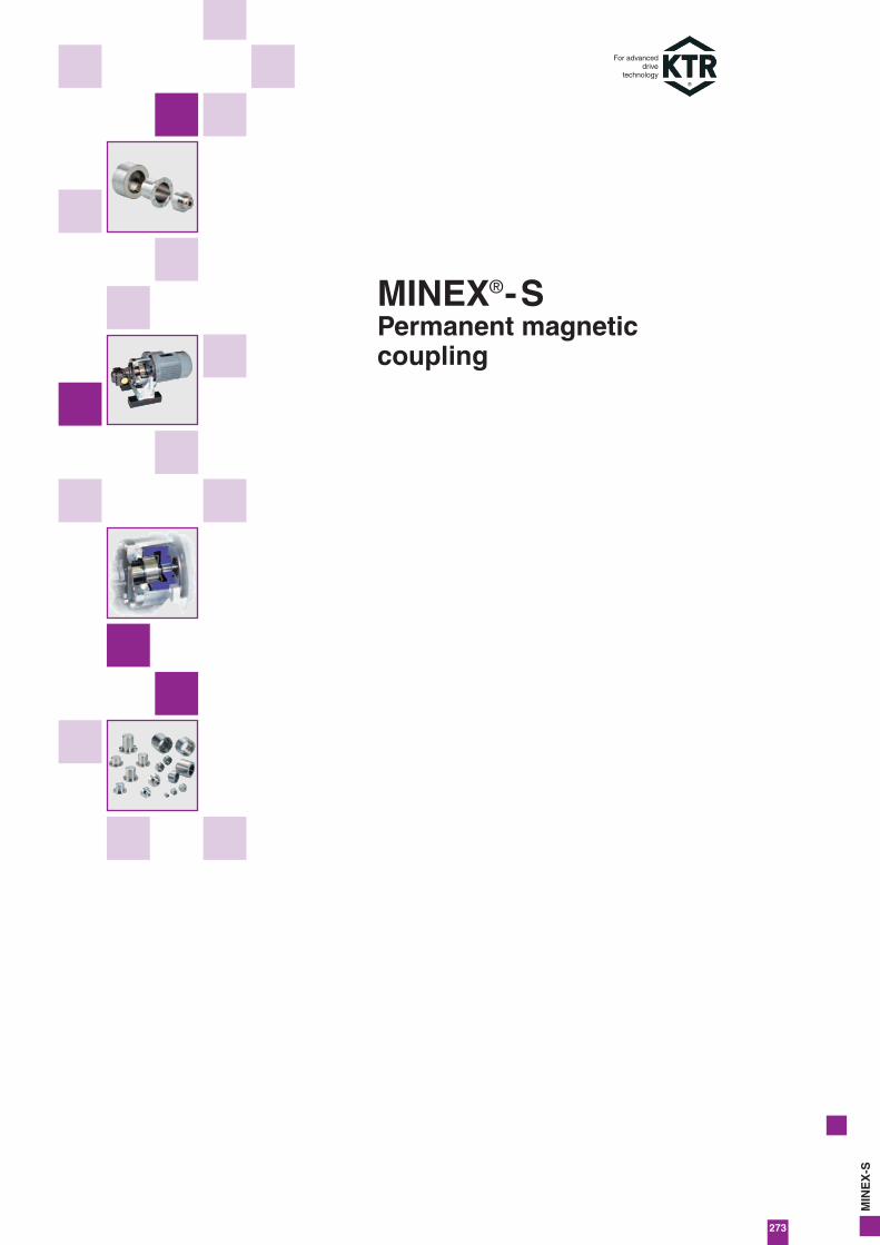
Containment shroud
Internal rotor
Run of flux lines
External rotor
Sealing function
The main component of the MINEX®-S is the containment shroud thatis fixed to the driven-sided power unit and separates internal and external rotor from each other. It ensures a low-vibration torque transmission working without mechanical connection and guarantees acompletely leak-proof separation of product and atmosphere. The sea-ling is achieved with a flat seal or an o-ring, thus eliminating the needto dynamically load the sealing elements.
The containment shroud and internal rotor are generally made fromstainless steel 1.4571 or Hastelloy.The magnets of the internal rotor are encapsulated to make them impervious to fluids and thus protected against external influences.
Since the containment shroud is a stationary component with a rotating magnetic field, it causes losses of eddy current. In order tokeep these low, the containment shroud is also available in Hastelloyfrom size 75 upwards ensuring a higher electrical resistance thanstainless steel. If eddy current losses can definitely be excluded, alter-native materials like PEEK or ceramics may be chose.
Function/Design
Torque transmission
The coupling consists of an external and an internal rotor. The external rotor has high-quality, permanent magnets of changing polarity on the inner side and the internal rotor has them on the outside. The external rotor is normally fixed on the drive side and themagnets are glued in the keyways. The magnets of the driven-sidedinternal rotor are cylindrically ground to ensure a minimal air gap andencapsulated through a magnetic cover that is impervious to fluids.
In their non-operative states the north and south poles of the rotors areopposite to each other and the magnetic field is completely symmetric.It is only when the rotors are twisted that the magnetic field lines aremoved, hence the torque is transmitted through the air gap. Then there is a synchronous operation under a constant torsion angle.
If the maximum coupling torque and the maximum torsion angle areexceeded, the power transmission is interrupted. Thus the MINEX®-Soffers an overload protection function of the drive train. After removing the cause of the overload (e. g. damage to the bearing, blok-king of the internal rotor) both rotors can be synchronised again andoperation is resumed.
General description
The MINEX®-S is a permanent-magnetic synchronous coupling thattransmits torque through magnetic forces between the internal and theexternal rotor.
It ensures a hermetic separation of the drive and the driven side in itsmain function as sealing element in pumps and agitators.For critical media like aggressive acids etc. it serves as a reliable sealand prevents serious leakages occuring.
On request KTR can manufacture special customer-specific types ofthe MINEX®-S in connection with KTR hydraulic components. Thus exi-sting pumps with a conventional shaft seal can be easily retrofittedwith the MINEX®-S.
For advanceddrive
technology
MINEX®-SPermanent magnetic couplingCoupling description
275
MIN
EX
-S
For advanceddrive
technology
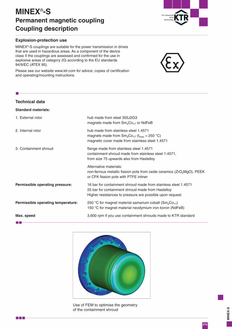
Use of FEM to optimise the geometry of the containment shroud
MINEX®-SPermanent magnetic couplingCoupling description
Explosion-protection use
MINEX®-S couplings are suitable for the power transmission in drivesthat are used in hazardous areas. As a component of the device class II the couplings are assessed and confirmed for the use in explosive areas of category 2G according to the EU standards94/9/EC (ATEX 95).
Please see our website www.ktr.com for advice, copies of certificationand operating/mounting instructions.
Technical data
Standard materials:
1. External rotor
2. Internal rotor
3. Containment shroud
Permissible operating pressure:
Permissible operating temperature:
Max. speed
hub made from steel 355J2G3magnets made from Sm2Co17 or NdFeB
hub made from stainless steel 1.4571magnets made from Sm2Co17 (tmax = 250 °C)magnetic cover made from stainless steel 1.4571
flange made from stainless steel 1.4571containment shroud made from stainless steel 1.4571, from size 75 upwards also from Hastelloy
Alternative materials:non-ferrous metallic fission pots from oxide ceramics (ZrO2MgO), PEEKor CFK fission pots with PTFE inliner
16 bar for containment shroud made from stainless steel 1.457125 bar for containment shroud made from HastelloyHigher resistances to pressure are possible upon request.
250 °C for magnet material samarium cobalt (Sm2Co17)150 °C for magnet material neodymium iron boron (NdFeB)
3,600 rpm if you use containment shrouds made to KTR standard
276
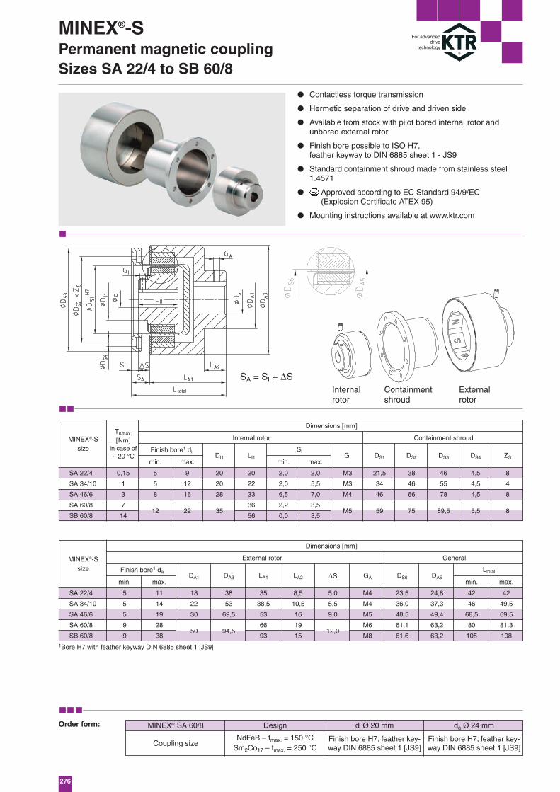
SA 22/4
SA 34/10
SA 46/6
SA 60/8
SB 60/8
SA 22/4
SA 34/10
SA 46/6
SA 60/8
SB 60/8
0,15
1
3
7
14
5
5
8
5
5
5
9
9
12
9
12
16
11
14
19
28
38
22 35
50 94,5 12,0
M5 59 75 89,5 5,5 8
20
20
28
18
22
30
38
53
69,5
35
38,5
53
66
93
8,5
10,5
16
19
15
5,0
5,5
9,0
M4
M4
M5
M6
M8
23,5
36,0
48,5
61,1
61,6
24,8
37,3
49,4
63,2
63,2
42
46
68,5
80
105
42
49,5
69,5
81,3
108
20
22
33
36
56
2,0
2,0
6,5
2,2
0,0
2,0
5,5
7,0
3,5
3,5
M3
M3
M4
21,5
34
46
38
46
66
46
55
78
4,5
4,5
4,5
8
4
8
DA1 DA3 LA1 LA2 �S GA DS6 DA5
DI1 LI1min. max.
GI DS1 DS2 DS3 DS4 ZS
SI
min. max. min. max.
min. max.
SA = SI + �S
NdFeB – tmax. = 150 °CSm2Co17 – tmax. = 250 °C
● Contactless torque transmission
● Hermetic separation of drive and driven side
● Available from stock with pilot bored internal rotor and unbored external rotor
● Finish bore possible to ISO H7, feather keyway to DIN 6885 sheet 1 - JS9
● Standard containment shroud made from stainless steel1.4571
● Approved according to EC Standard 94/9/EC (Explosion Certificate ATEX 95)
● Mounting instructions available at www.ktr.com
Design di Ø 20 mm
Finish bore H7; feather key-way DIN 6885 sheet 1 [JS9]
Finish bore H7; feather key-way DIN 6885 sheet 1 [JS9]
da Ø 24 mmMINEX® SA 60/8
Coupling size
Order form:
1Bore H7 with feather keyway DIN 6885 sheet 1 [JS9]
MINEX®-SPermanent magnetic couplingSizes SA 22/4 to SB 60/8
For advanceddrive
technology
total
Ltotal
Dimensions [mm]
Dimensions [mm]
Finish bore1 di
Finish bore1 da
Internal rotor
External rotor
Containment shroud
General
TKmax.
[Nm]in case of~ 20 °C
MINEX®-Ssize
MINEX®-Ssize
Internalrotor
Containmentshroud
Externalrotor
277
MIN
EX
-S
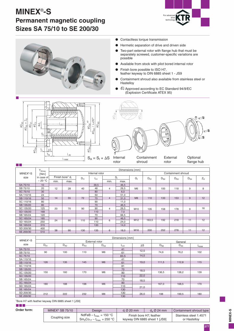
SA 75/10SB 75/10SC 75/10SA 110/16SB 110/16SC 110/16SB 135/20SC 135/20SD 135/20SB 165/24SC 165/24SD 165/24SE 165/24SD 200/30SE 200/30
SA 75/10SB 75/10SC 75/10SA 110/16SB 110/16SC 110/16SB 135/20SC 135/20SD 135/20SB 165/24SC 165/24SD 165/24SE 165/24SD 200/30SE 200/30
4161
83,54161817090
1107090
110130130130
10203024508080125168120185250315400510
12
90
126
150
180
100
135
160
188
110
145
170
198
M6
M6
M6
M6
212 222 232 M6
74,6
111,5
136,5
167,0
198
76,2
112,8
138,2
168,5
199,5
102
115
139
170
180
12,5
19,0
18,5
14,5
22,0
18,5
21,0
26,0
14
20
24
28
55
70
90
40
72
90
110
4
4
4
6
M6
M8
M10
M12
75
110
135
163,5
100
133
158
192
118
153
178
218
9
9
9
11
8
12
16
12
38 90 130 135 18,06 M16 200 252 278 11 12
39,548805070907090
1107090
110130
46,526,56,0
51,031,011,046,526,57,0
66,546,524,014,0
DA1 DA2 DA3 DA4 LA1 �S DS6 DA5
DI1 LI1min. max.
GI DS1 DS2 DS3 DS4 ZSSI
min. max.
SA = SI + �S
NdFeB – tmax. = 150 °CSm2Co17 – tmax. = 250 °C
Ltotal
total
● Contactless torque transmission
● Hermetic separation of drive and driven side
● Two-part external rotor with flange hub that must be separately screwed, customer-specific variations are possible
● Available from stock with pilot bored internal rotor
● Finish bore possible to ISO H7, feather keyway to DIN 6885 sheet 1 - JS9
● Containment shroud also available from stainless steel orHastelloy
● Approved according to EC Standard 94/9/EC (Explosion Certificate ATEX 95)
Design di Ø 20 mm
Finish bore H7; feather keyway DIN 6885 sheet 1 [JS9]
da Ø 24 mm Containment shroud type
Stainless steel 1.4571or Hastelloy
MINEX® SB 75/10
Coupling size
Order form:
1Bore H7 with feather keyway DIN 6885 sheet 1 [JS9]
For advanceddrive
technology
MINEX®-SPermanent magnetic couplingSizes SA 75/10 to SE 200/30
Dimensions [mm]
Dimensions [mm]
Finish bore1 di
Internal rotor
External rotor
Containment shroud
General
TKmax.
[Nm]in case of~ 20 °C
MINEX®-Ssize
MINEX®-Ssize
Internalrotor
Containmentshroud
External rotor
Optionalflange hub
278
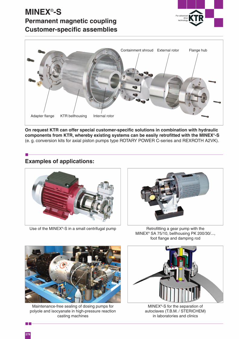
Adapter flange KTR bellhousing
Containment shroud
Internal rotor
External rotor Flange hub
MINEX®-SPermanent magnetic couplingCustomer-specific assemblies
For advanceddrive
technology
On request KTR can offer special customer-specific solutions in combination with hydrauliccomponents from KTR, whereby existing systems can be easily retrofitted with the MINEX®-S(e. g. conversion kits for axial piston pumps type ROTARY POWER C-series and REXROTH A2VK).
Examples of applications:
Use of the MINEX®-S in a small centrifugal pump Retrofitting a gear pump with theMINEX® SA 75/10, bellhousing PK 200/30/...,
foot flange and damping rod
Maintenance-free sealing of dosing pumps for polyole and isocyanate in high-pressure reaction
casting machines
MINEX®-S for the separation of autoclaves (T.B.M. / STERICHEM)
in laboratories and clinics